
XPS M140 - Laptop DELL - Free user manual and instructions
Find the device manual for free XPS M140 DELL in PDF.


| Product Type | Laptop |
| Brand | Dell |
| Model | XPS M140 |
| Display | 14.1-inch WXGA (1280x800) TFT LCD |
| Processor | Intel Pentium M (up to 2.13 GHz) |
| Memory | Up to 2 GB DDR2 SDRAM (two SO-DIMM slots) |
| Hard Drive | 2.5-inch SATA HDD (up to 100 GB, 5400 RPM) |
| Optical Drive | CD-RW/DVD-ROM combo or DVD±RW |
| Wireless | Mini PCI 802.11b/g (optional) |
| Bluetooth | Internal Bluetooth module (optional) |
| Battery | 6-cell or 9-cell rechargeable lithium-ion (removable) |
| Dimensions (W x D x H) | 13.4 x 9.5 x 1.3 inches (340 x 241 x 33 mm) |
| Weight | Starting at 5.5 lbs (2.5 kg) |
| AC Adapter | 65W input: 100-240V, output: 19.5V DC |
| Operating System | Windows XP Home or Professional |
| Ports | USB 2.0 (4), VGA, S-Video, IEEE 1394, headphone, microphone, RJ-45, RJ-11 |
| Repairability | High – service manual provided; user-replaceable components include RAM, HDD, optical drive, keyboard, fan, and more. |
| Safety Notices | Anti-static precautions required; disconnect AC and battery before servicing; follow ESD guidelines. |
Frequently Asked Questions - XPS M140 DELL
User questions about XPS M140 DELL
0 question about this device. Answer the ones you know or ask your own.
Ask a new question about this device
Download the instructions for your Laptop in PDF format for free! Find your manual XPS M140 - DELL and take your electronic device back in hand. On this page are published all the documents necessary for the use of your device. XPS M140 by DELL.
USER MANUAL XPS M140 DELL
| Before You Begin | Display Assembly and Display Latch |
| System Components | Palm Rest |
| Internal Card With Bluetooth® Wireless Technology | Microprocessor Thermal-Cooling Assembly |
| Hard Drive | Fan |
| Optical Drive | Microprocessor Module |
| Memory Module and Modem | Speakers |
| Hinge Cover | System Board |
| Keyboard | BIOS Updates |
| Coin-Cell Battery | Pin Assignments for I/O Connectors |
| Wireless Mini PCI Card |
Notes, Notices, and Cautions
NOTE: A NOTE indicates important information that helps you make better use of your computer.
NOTICE: A NOTICE indicates either potential damage to hardware or loss of data and tells you how to avoid the problem.
CAUTION: A CAUTION indicates a potential for property damage, personal injury, or death.
Information in this document is subject to change without notice.
© 2005 Dell Inc. All rights reserved.
Reproduction in any manner whatsoever without the written permission of Dell Inc. is strictly forbidden.
Trademarks used in this text: Dell, the DELL logo, and Inspiron are trademarks of Dell Inc.; Intel is a registered trademark of Intel Corporation; Microsoft and Windows are registered trademarks of Microsoft Corporation; Bluetooth is a trademark owned by Bluetooth SIG, Inc. and is used by Dell Inc. under license.
Other trademarks and trade names may be used in this document to refer to either the entities claiming the marks and names or their products. Dell Inc. disclaims any proprietary interest in trademarks and trade names other than its own.
Model PP19L
October 2005 Rev. A00
Before You Begin
Dell™ XPS M140 Service Manual
• Preparing to Work Inside the Computer
Recommended Tools
Computer Orientation
Screw Identification
Preparing to Work Inside the Computer
CAUTION: Before you perform any of the procedures in this section, follow the safety instructions in the Product Information Guide.
NOTICE: Only a certified service technician should perform repairs on your computer. Damage due to servicing that is not authorized by Dell is not covered by your warranty.
NOTICE: To avoid electrostatic discharge, ground yourself by using a wrist grounding strap or by periodically touching an unpainted metal surface (such as the back panel) on the computer.
NOTICE: Handle components and cards with care. Do not touch the components or contacts on a card. Instead, hold a card by its edges or by its metal mounting bracket. Hold a component such as a microprocessor by its edges, not by its pins.
NOTICE: When disconnecting a cable, pull on the cable's connector or on its strain-relief loop, not on the cable itself. Some cables have connectors with locking tabs; before disconnecting this type of cable, press inward on the locking tabs to release the connector. When connecting or disconnecting a cable, ensure that the connectors are correctly oriented and aligned to avoid damage to the connector and/or the connector's pins.
NOTICE: To avoid damaging the computer, always perform the following steps before you begin working inside the computer.
- Ensure that the work surface is flat and clean to prevent scratching the computer cover.
- Save any work in progress and exit all open programs.
- Turn off the computer and all attached devices.
NOTE: Ensure that the computer is off and not in a power management mode. If you cannot shut down the computer using the operating system, press and hold the power button for 4 seconds.
- Disconnect the computer from the electrical outlet.
NOTICE: To avoid damaging the system board, wait 10 to 20 seconds before disconnecting any attached devices.
-
Disconnect all attached devices.
-
Disconnect all external cables from the computer.
-
Close the display and turn the computer upside down on a flat work surface.
NOTICE: To avoid damaging the system board, you must remove the main battery before servicing the computer.
- Slide and hold the battery bay latch release on the bottom of the computer, then pull the battery out of the battery bay.
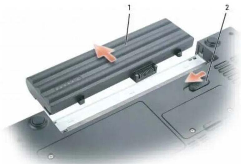
text_image
Laptop rear panel with labeled components and directional arrows indicating movement or assembly1 battery 2 battery bay latch release
Recommended Tools
The procedures in this document will require one or more of the following tools:
• Small flat-blade screwdriver
• Phillips screwdriver
- Small plastic scribe
- Flash BIOS update (see the Dell support website at support.dell.com)
Computer Orientation

text_image
1 2 3 4| 1 front 2 | left 3 back | ||||
| 4 right |
Screw Identification
The following chart provides the number of screws used to secure the various system components and their corresponding sizes. When removing and replacing components, print the screw identification chart as a placemat to lay out and keep track of the screws.

text_image
M2 × 3 mm M2.5 × 3 mm M2.5 × 5 mm M2.5 × 8 mm M3 × 3 mmOptical Drive:(1 each – optional) M2.5 x 8 mm M2.5 x 8 mm | Modem:(1 each) M2 x 3 mm M2 x 3 mm | Bluetooth Module:(1 each)[SKZX]M2 x 3 mm |
| Hinge Cover:(2 each) | Display Assembly:(4 each) | Display Bezel (screw):(6 each) |
 M2 x 3 mm M2 x 3 mm |  M2.5 x 5 mm M2.5 x 5 mm | [2KSD]M2.5 x 5 mm |
Display Bezel (rubber bumper):(6 each) | Display Panel:(6 each) M2 x 3 mm M2 x 3 mm | Palm Rest (top):(4 each) M2.5 x 5 mm M2.5 x 5 mm |
Palm Rest (bottom):(11 each) M2.5 x 8 mm M2.5 x 8 mm | Fan:(3 each) M2.5 x 5 mm M2.5 x 5 mm | Speakers:(3 total) M2.5 x 5 mm M2.5 x 5 mm |
System Board (top):(1 each) M2.5 x 5 mm M2.5 x 5 mm | System Board (bottom):(2 each) M2 x 3 mm M2 x 3 mm |
Back to Contents Page
Back to Contents Page
System Components
Dell™ XPS M140 Service Manual
NOTICE: Only a certified service technician should perform repairs on your computer. Damage due to servicing that is not authorized by Dell is not covered by your warranty.
Exploded View of the Computer
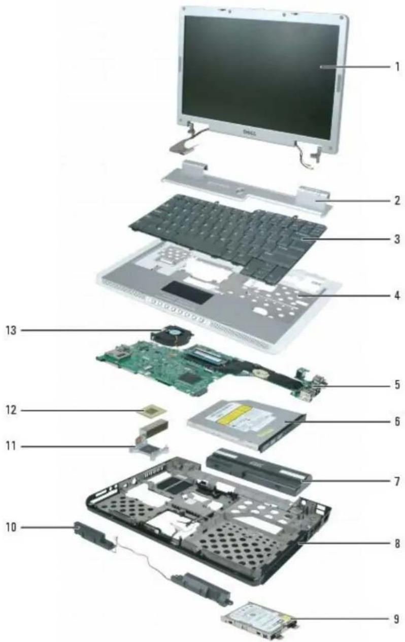
text_image
Exploded view diagram of a device showing internal components like CPU, memory, and circuit board with numbered labels.| 1 | display assembly 6 optical | drive | 11 microprocessor | or thermal-cooling assembly |
| 2 | hinge cover 7 main battery | 12 | microprocessor | |
| 3 | keyboard 8 computer | base | 13 fan | |
| 4 | palm rest (with touch pad) | 9 hard drive | ||
| 5 | system board 10 speakers | |||
Back to Contents Page
Internal Card With Bluetooth® Wireless Technology
Dell™ XPS M140 Service Manual
- Removing the Bluetooth Module
- Replacing the Bluetooth Module

NOTE: If you ordered the optional internal card with Bluetooth wireless technology at the same time that you ordered your computer, the card is already installed.
Removing the Bluetooth Module

CAUTION: Before you perform any of the procedures in this section, follow the safety instructions in the Product Information Guide.

NOTICE: To avoid electrostatic discharge, ground yourself by using a wrist grounding strap or by periodically touching an unpainted metal surface (such as the back panel) on the computer.
- Follow the instructions in Preparing to Work Inside the Computer.
- Loosen the two captive screws on the modem/Mini PCI/wireless cover, then remove the cover and set it aside.
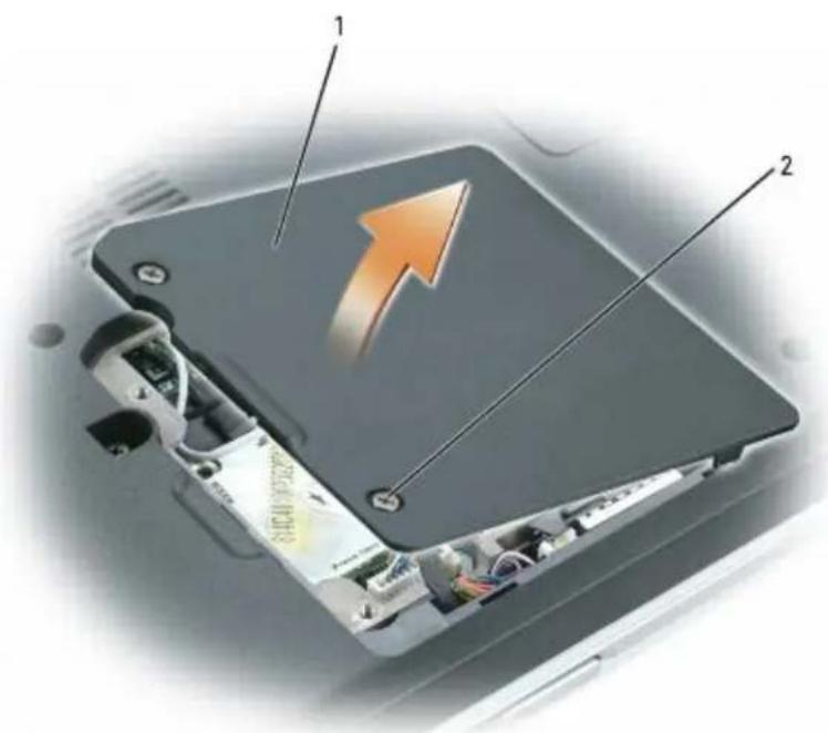
text_image
Diagram of an electronic device showing internal components with labeled parts and an upward arrow indicating direction.1 modem/Mini PCI/wireless cover 2 captive screws (2)
- Remove the M2 x 3-mm screw securing the Bluetooth module and set it aside.
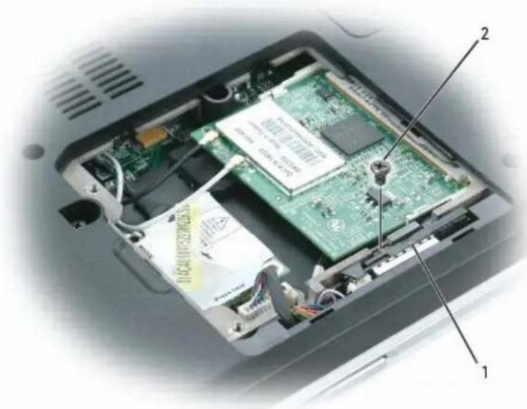
natural_image
Internal view of an open computer case showing internal components like a green circuit board and memory card (no text or symbols visible)1 Bluetooth module 2 M2 x 3-mm screw
- Lift the Bluetooth module from its compartment.
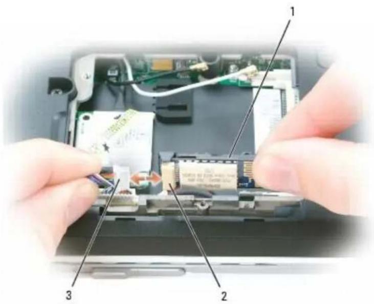
- Grasp the card and gently pull it apart from the connector cable.
NOTE: Do not disconnect the Bluetooth connector cable from the system board.
text_image
Laptop interior photo showing hands installing components with numbered labels 1, 2, and 31 Bluetooth module 2 Bluetooth module connector 3 Bluetooth connector cable
Replacing the Bluetooth Module
CAUTION: Before you perform any of the procedures in this section, follow the safety instructions in the Product Information Guide.
NOTICE: To avoid electrostatic discharge, ground yourself by using a wrist grounding strap or by periodically touching an unpainted metal surface (such as the back panel) on the computer.
- Follow the instructions in Preparing to Work Inside the Computer.
- Follow the instructions in Removing the Bluetooth Module, as applicable.
- Connect the new Bluetooth module to the connector cable.
- Place the Bluetooth module in its compartment.
- Replace the M2 x 3-mm screw to secure the Bluetooth module to the base of the computer.
- Replace the modem/Mini PCI/wireless cover and tighten the screws.
Back to Contents Page
Back to Contents Page
Hard Drive
Dell™ XPS M140 Service Manual
Removing the Hard Drive
Replacing the Hard Drive
- Returning a Hard Drive to Dell
Removing the Hard Drive
CAUTION: Before you perform any of the procedures in this section, follow the safety instructions in the Product Information Guide.
CAUTION: Do not touch the metal housing of the hard drive if you remove the hard drive from the computer while the drive is hot.
NOTICE: To prevent data loss, turn off your computer before removing the hard drive. Do not remove the hard drive while the computer is on, in standby mode, or in hibernate mode.
NOTICE: To avoid electrostatic discharge, ground yourself by using a wrist grounding strap or by periodically touching an unpainted metal surface (such as the back panel) on the computer.
NOTICE: To avoid damaging the hard drive, handle the drive with care.
NOTE: Dell does not guarantee compatibility or provide support for hard drives obtained from sources other than Dell.
NOTE: If you are installing a hard drive obtained from a source other than Dell, you may need to install an operating system, drivers, and utilities on the new drive.
- Follow the instructions in Preparing to Work Inside the Computer.
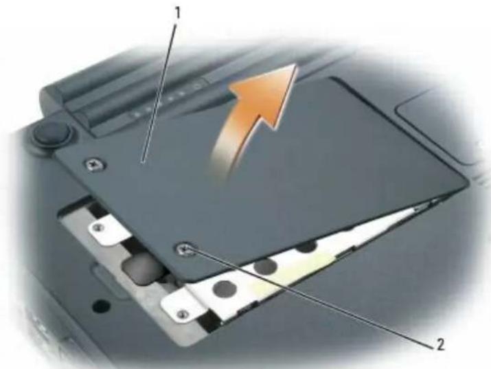
- Loosen the two captive screws securing the hard drive cover, then remove the cover and set it aside.
text_image
Diagram of a computer flash drive showing internal components and an upward arrow indicating motion or direction.1 hard drive cover 2 captive screws (2)

NOTICE: When the hard drive is not in the computer, store it in protective, antistatic packaging. See "Protecting Against Electrostatic Discharge" in the Product Information Guide.
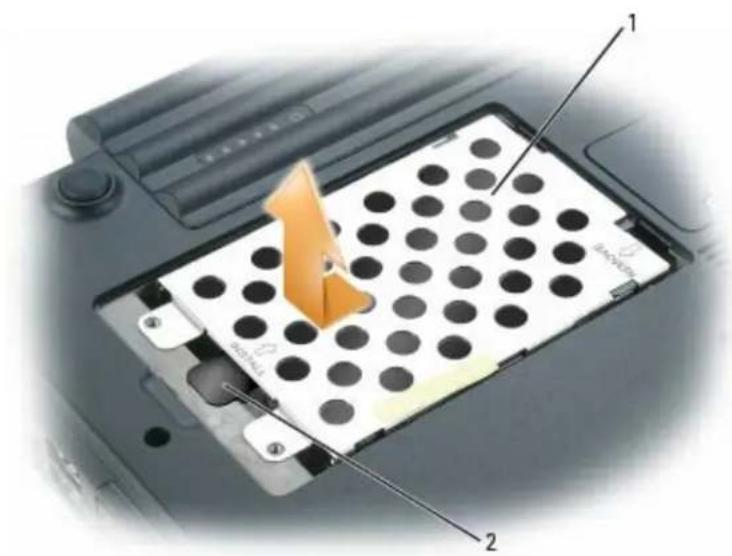
- Use the pull-tab to slide the hard drive toward the screw holes, then lift the drive straight up to remove it from the computer.
text_image
Diagram of a device with labeled components, showing a grid-patterned plate and numbered parts (1 and 2)1 hard drive 2 pull tab
Replacing the Hard Drive

CAUTION: Before you perform any of the procedures in this section, follow the safety instructions in the Product Information Guide.
NOTICE: To avoid electrostatic discharge, ground yourself by using a wrist grounding strap or by periodically touching an unpainted metal surface (such as the back panel) on the computer.
- Follow the instructions in Preparing to Work Inside the Computer.
- Follow the instructions in Removing the Hard Drive.
NOTICE: Use firm and even pressure when sliding the hard drive into place. Excessive force may result in damage to the connector.
- Place the new hard drive into the bay, then slide it away from the screw holes into the connector until it is fully seated.
- Replace the hard drive cover and tighten the screws.
- Install the operating system for your computer, if necessary (see "Restoring Your Operating System" in your Owner's Manual).
- Install the drivers and utilities for your computer, if necessary (see "Reinstalling Drivers and Utilities" in your Owner's Manual).
Returning a Hard Drive to Dell
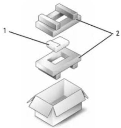
Return your hard drive to Dell in the replacement drive's foam packaging. Otherwise, the hard drive may be damaged in transit.
NOTE: The hard drive should be inserted in the replacement drive's antistatic bag before being placed in the foam packaging.
natural_image
Exploded view diagram of a mechanical assembly with two labeled components (1 and 2), no text or symbols present.1 hard drive (in antistatic bag) 2 foam packaging
Back to Contents Page
Back to Contents Page
Optical Drive
Dell™ XPS M140 Service Manual
About the Device Security Screw
- Removing the Optical Drive
- Replacing the Optical Drive
About the Device Security Screw

NOTE: You do not need to install the device security screw unless you want to prevent the optical drive from being easily removed.
Your Dell™ computer ships with a CD/DVD drive installed in the optical drive bay along with an M2.5 x 8-mm device security screw. If the security screw is not already installed, it will be packaged separately. When you insert a drive into the bay, you can install the device security screw to prevent the drive from being easily removed.
Removing the Optical Drive

CAUTION: Before you perform any of the procedures in this section, follow the safety instructions in the Product Information Guide.

NOTICE: To prevent damage to optical drives and other devices, store them in a safe, dry place when they are not installed in the computer. Avoid pressing down on them or placing heavy objects on top of them.
- Follow the instructions in Preparing to Work Inside the Computer.
- Use a Phillips screwdriver to remove the M2.5 x 8-mm device security screw, if installed, from the indentation in the bottom of the computer.
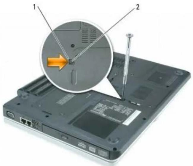
text_image
Laptop screen with labeled components and a magnified view showing a CD drive mechanism with an orange arrow indicating motion.1 indention 2 M2.5 x 8-mm device security screw (optional)
- Insert the screwdriver into the indentation and push the notch on the metal tab to release the drive from the bay.
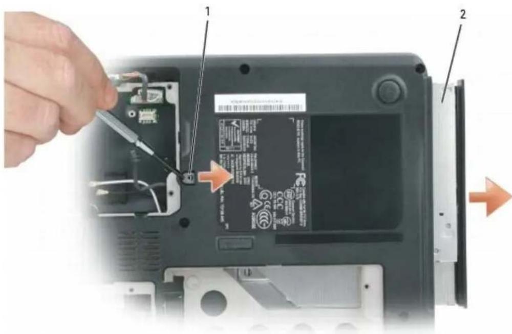
text_image
Laptop screen showing battery label adjustment with tool and arrows indicating action1 metal tab 2 optical drive
- Pull the drive out of the bay.
Replacing the Optical Drive

CAUTION: Before you perform any of the procedures in this section, follow the safety instructions in the Product Information Guide.
- Follow the instructions in Preparing to Work Inside the Computer.
- Follow the instructions in Removing the Optical Drive.
- Slide the new drive into the bay until it snaps securely into place.
- Replace the M2.5 x 8-mm device security screw (optional).
Back to Contents Page
Back to Contents Page
Memory Module and Modem
Dell™ XPS M140 Service Manual
Removing a Memory Module
Replacing a Memory Module
Modem
Your Dell computer comes equipped with two memory slots/connectors labeled DIMM A and DIMM B. DIMM A (located under the keyboard) holds the primary memory module as configured from the factory. DIMM B (located on the bottom of the computer) holds any additional memory you may have ordered. If you did not order additional memory, DIMM B will be empty.
Generally, if you are adding memory, you will install a memory module in DIMM B only. If you are upgrading the memory, you may need to install memory modules in DIMM A and DIMM B, depending on the extent of the upgrade.

NOTE: Memory modules purchased from Dell ^™ are covered under your computer warranty.
Removing a Memory Module
CAUTION: Before you perform any of the procedures in this section, follow the safety instructions in the Product Information Guide.
NOTICE: To avoid electrostatic discharge, ground yourself by using a wrist grounding strap or by periodically touching an unpainted metal surface (such as the back panel) on the computer.
Memory Module DIMM B
- Follow the instructions in Preparing to Work Inside the Computer.
- Loosen the two captive screws securing the memory module cover, then remove the cover and set it aside.
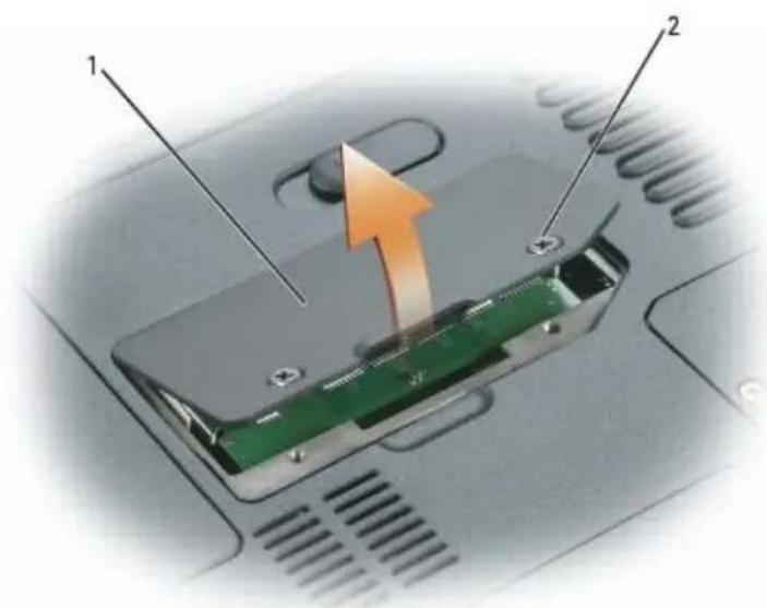
text_image
Diagram of a device showing internal components with labeled parts and an orange arrow indicating motion or flow.1 memory module cover 2 captive screws (2)

NOTICE: To prevent damage to the memory module connector, do not use tools of any kind to spread the metal clips that secure the module.
- Use your fingertips to carefully spread apart the metal clips securing each end of the memory module until the module pops up.

natural_image
Diagram of a computer motherboard showing internal components and airflow direction (no text or symbols)1 memory module 2 metal retention clips (2)
- Remove the module from the connector at a 45-degree angle.
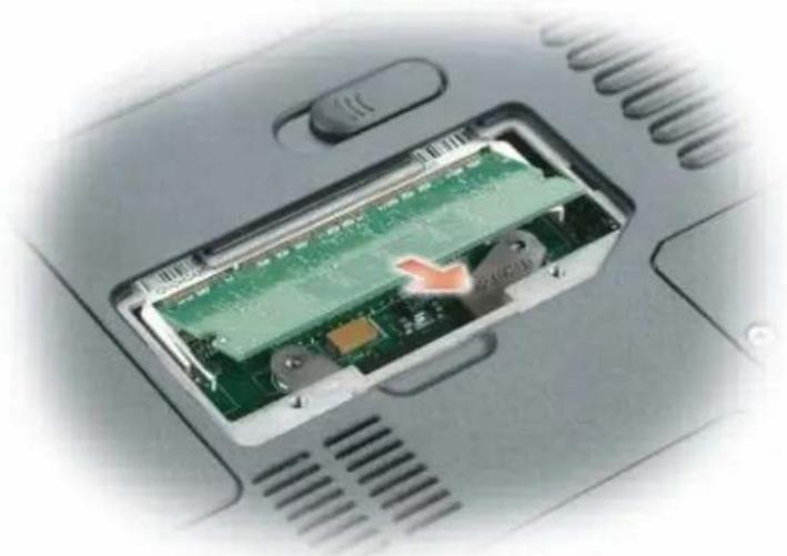
natural_image
Close-up of a green circuit board inside a device casing, with a red arrow indicating a component (no visible text or symbols)Memory Module DIMM A
- Follow the instructions in Preparing to Work Inside the Computer.
- Remove the hinge cover (see Removing the Hinge Cover).
- Remove the keyboard (see Removing the Keyboard).
- Loosen the two captive screws securing the memory module cover, then remove the cover and set it aside.
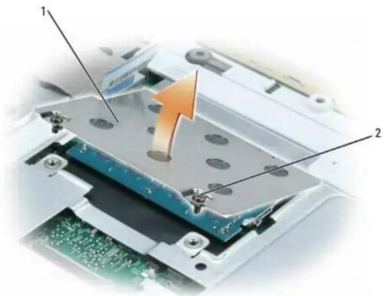
natural_image
Close-up of a computer motherboard with a highlighted component and an orange arrow indicating motion (no text or symbols)1 memory module cover 2 captive screws (2)

NOTICE: To prevent damage to the memory module connector, do not use tools of any kind to spread the metal clips that secure the module.
- Use your fingertips to carefully spread apart the metal clips securing each end of the memory module until the module pops up.
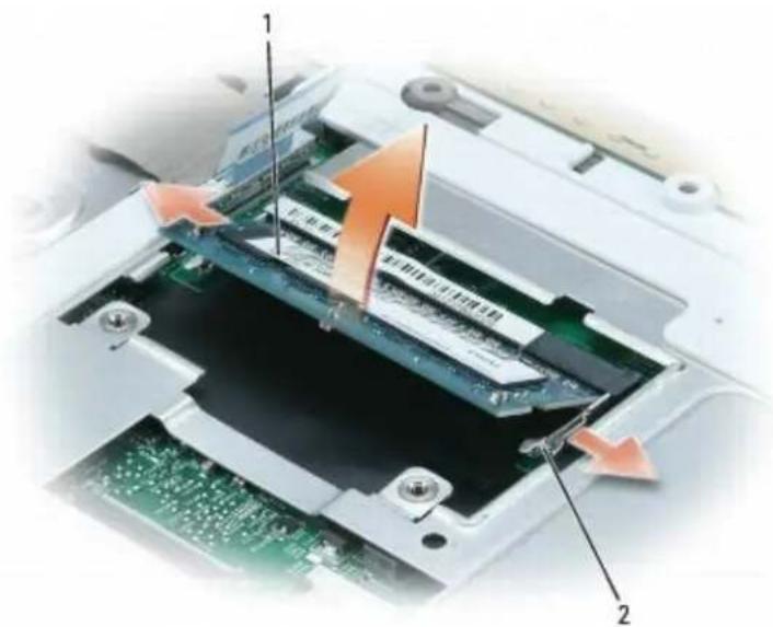
text_image
Diagram showing a device's internal structure with labeled components and directional arrows indicating movement or flow.1 memory module 2 metal retention clips (2)
- Remove the memory module from the connector at a 45-degree angle.
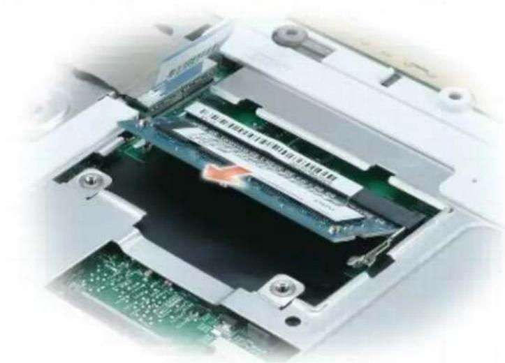
natural_image
Interior view of a computer drive showing internal components and a green circuit board (no visible text or symbols)Replacing a Memory Module
CAUTION: Before you perform any of the procedures in this section, follow the safety instructions in the Product Information Guide.
NOTICE: To avoid electrostatic discharge, ground yourself by using a wrist grounding strap or by periodically touching an unpainted metal surface (such as the back panel) on the computer.
NOTICE: If you need to install more than one memory module, install a memory module in the memory slot labeled DIMM A before installing a module in the slot labeled DIMM B. Insert memory modules at a 45-degree angle to avoid damaging the connector.
NOTE: If a memory module is not installed properly, the computer may not boot. No error message will be displayed for this type of failure.
-
Follow the instructions in Preparing to Work Inside the Computer.
-
Remove the appropriate memory module cover and memory module, if installed (see Removing a Memory Module).
-
Install the new memory module:
a. Align the notch in the memory module edge connector with the tab in the connector slot.
b. Slide the module firmly into the slot at a 45-degree angle, and then rotate the module down until it clicks into place. If you do not feel the click, remove the module and reinstall it.

natural_image
Close-up of a computer motherboard showing internal components and a highlighted circuit board (no text or symbols visible)| 1 memory module |
NOTICE: If the memory module cover is difficult to close, remove the memory module and reinstall it. Forcing the cover to close may damage your computer.
-
Replace the memory module cover and tighten the screws.
-
Replace the keyboard (see Replacing the Keyboard—DIMM A only).
-
Replace the hinge cover (see Replacing the Hinge Cover—DIMM A only).
If You Are Replacing Memory
As the computer boots, it detects the installed memory. The system configuration information remains the same.
If You Are Adding or Upgrading Memory
As the computer boots, it detects the change in memory and automatically updates the system configuration information.
Confirming Installed Memory
To confirm the amount of memory installed in the computer, use one of the following methods:
- Click the Start button, then click Help and Support. Under Pick a task, click Use Tools to view your computer information and diagnose problems. Under Tools, click My Computer Information, then click Find information about the hardware installed on this computer.
- Access the System Setup Program at startup by pressing
Modem

NOTE: If you ordered the optional modem at the same time that you ordered your computer, the modem is already installed.
Removing the Modem

CAUTION: Before you perform any of the procedures in this section, follow the safety instructions in the Product Information Guide.

NOTICE: To avoid electrostatic discharge, ground yourself by using a wrist grounding strap or by periodically touching an unpainted metal surface (such as the back panel) on the computer.
- Follow the instructions in Preparing to Work Inside the Computer.
- Loosen the two captive screws on the modem/Mini PCI/wireless cover, then remove the cover and set it aside.
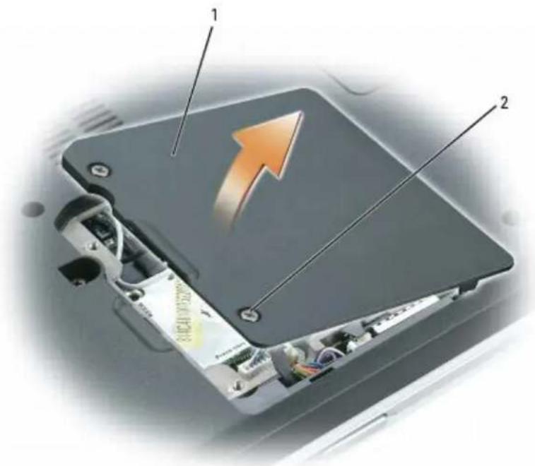
text_image
Diagram of a device showing internal components with labeled parts and an orange arrow indicating direction1 modem/Mini PCI/wireless cover 2 captive screws (2)
- Disconnect the antenna cables from the Mini PCI card, if applicable.
NOTE: The Mini PCI card is optional and may not be installed if one was not ordered with the computer.

natural_image
Interior view of a computer with visible circuit board and internal components (no text or symbols)1 Mini PCI antenna cables
-
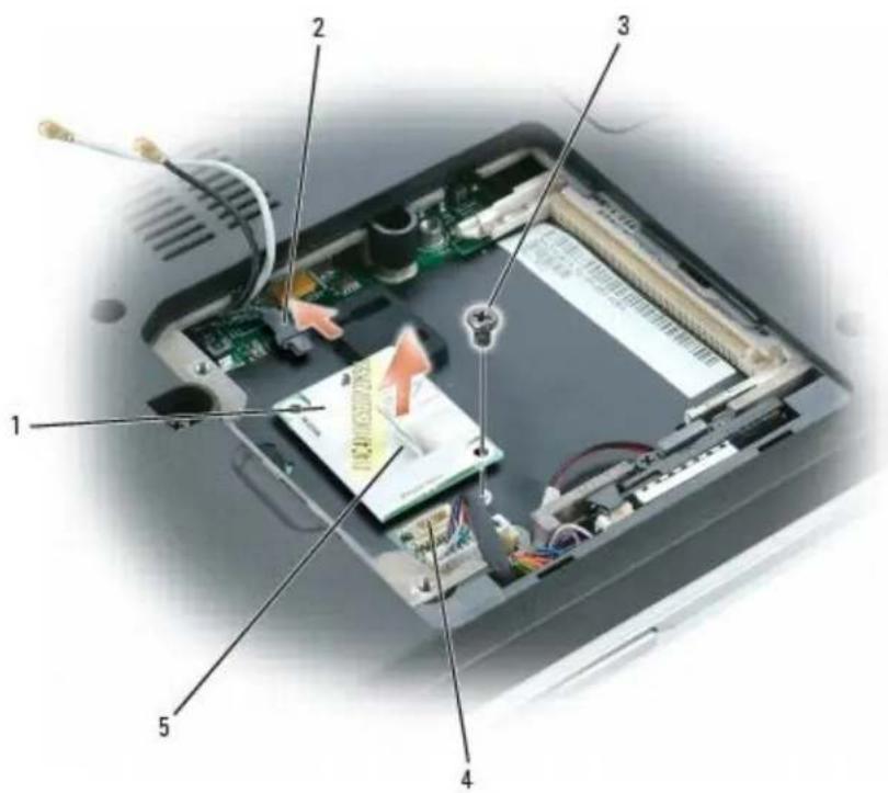
Remove the M2 x 3-mm screw securing the modem to the system board and set it aside.
-
Pull straight up on the attached pull-tab to disconnect the modem from the connector on the system board.
-
Disconnect the modem cable from the modem.
text_image
Labeled diagram of an open computer case showing internal components and a central CPU socket with visible wiring and connectors.| 1 modem 3 M2 x 3-mm screw 5 pull tab | ||
| 2 modem cable 4 system board connector |
Replacing the Modem

CAUTION: Before you perform any of the procedures in this section, follow the safety instructions in the Product Information Guide.

NOTICE: To avoid electrostatic discharge, ground yourself by using a wrist grounding strap or by periodically touching an unpainted metal surface (such as the back panel) on the computer.
-
Follow the instructions in Preparing to Work Inside the Computer.
-
Follow the instructions in Removing the Modem, as applicable.

NOTICE: The modem connectors are keyed to ensure correct insertion. If you feel resistance, check the connectors for proper alignment.
-
Connect the modem cable to the new modem.
-
Connect the modem to the system board.
Align the modem with the screw hole and press the modem into the connector on the system board.
- Replace the M2 x 3-mm screw and secure the modem to the system board.
- Connect the Mini PCI antenna cables, if applicable.
- Replace the modem/Mini PCI/wireless cover and tighten the screws.
Back to Contents Page
Back to Contents Page
Hinge Cover
Dell™ XPS M140 Service Manual
- Removing the Hinge Cover
• Replacing the Hinge Cover
Removing the Hinge Cover
CAUTION: Before you perform any of the procedures in this section, follow the safety instructions in the Product Information Guide.
NOTICE: To avoid electrostatic discharge, ground yourself by using a wrist grounding strap or by periodically touching an unpainted metal surface (such as the back panel) on the computer.
NOTICE: The hinge cover is fragile and can be damaged if extreme force is used. Exercise care when removing the hinge cover.
- Follow the instructions in Preparing to Work Inside the Computer.
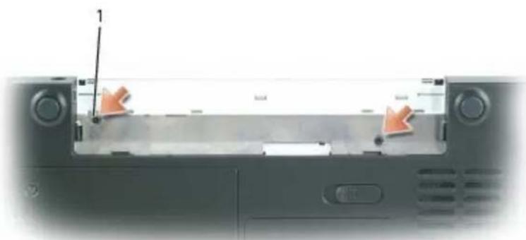
- Remove the two M2 x 3-mm screws inside the battery bay.
natural_image
Close-up of a laptop keyboard with two orange arrows pointing to the left panel (no visible text or symbols)1 M2 x 3-mm screws (2)
- Turn the computer over, and then open the display all the way (180 degrees) so that it rests flat on your work surface.
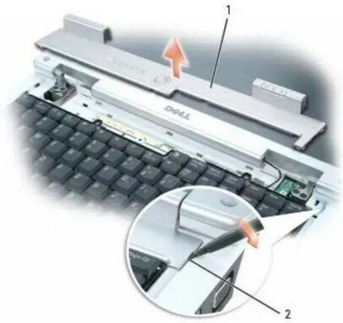
- Insert a plastic scribe into the indent along the right edge of the hinge cover to pry the hinge cover loose.
- Moving from right to left, ease the hinge cover up and remove it from the computer.
text_image
1 Dell 21 hinge cover 2 indent
Replacing the Hinge Cover
CAUTION: Before you perform any of the procedures in this section, follow the safety instructions in the Product Information Guide.
NOTICE: To avoid electrostatic discharge, ground yourself by using a wrist grounding strap or by periodically touching an unpainted metal surface (such as the back panel) on the computer.
- Follow the instructions in Preparing to Work Inside the Computer.
The hinge cover is fragile and can be damaged if extreme force is used. Exercise care when replacing the hinge cover.
-
Follow the instructions in Removing the Hinge Cover.
-
Align the tabs along the left edge of the new hinge cover with the corresponding notches in the computer.
-
Moving from left to right, press down until the hinge cover snaps into place.
-
Replace the two M2 x 3-mm screws inside the battery bay to secure the hinge cover.
Back to Contents Page
Back to Contents Page
Keyboard
Dell™ XPS M140 Service Manual
- Removing the Keyboard
Replacing the Keyboard
Removing the Keyboard
CAUTION: Before you perform any of the procedures in this section, follow the safety instructions in the Product Information Guide.
NOTICE: To avoid electrostatic discharge, ground yourself by using a wrist grounding strap or by periodically touching an unpainted metal surface (such as the back panel) on the computer.
-
Follow the instructions in Preparing to Work Inside the Computer.
-
Remove the hinge cover (see Removing the Hinge Cover).
NOTICE: The key caps on the keyboard are fragile, easily dislodged, and time-consuming to replace. Exercise care when removing and handling the keyboard.
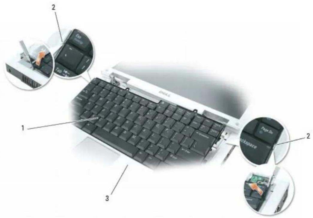
- Insert a plastic scribe or small flat-blade screwdriver near the keyboard retention tab on the left or right side of the palmrest to pry one side of the keyboard loose, then pry the remaining side of the keyboard loose, as necessary.
text_image
1 2 3 2 Page 10 Backspace1 keyboard 2 keyboard retention tabs 3 palmrest
- Lift the keyboard and hold it up and slightly forward to allow access to the keyboard connector.
- Release the latch on the system board connector to disconnect the keyboard cable.
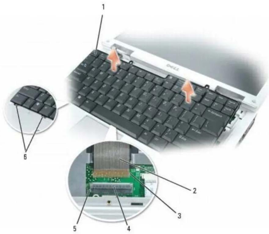
text_image
1 2 3 4 5 6| 1 | keyboard 3 keyboard | connector tabs 5 system board | connector slots |
| 2 | keyboard cable 4 system board | connector 6 keyboard | tabs (6) |
Replacing the Keyboard
CAUTION: Before you perform any of the procedures in this section, follow the safety instructions in the Product Information Guide.
NOTICE: To avoid electrostatic discharge, ground yourself by using a wrist grounding strap or by periodically touching an unpainted metal surface (such as the back panel) on the computer.
- Follow the instructions in Preparing to Work Inside the Computer.
- Follow the instructions in Removing the Keyboard.
NOTICE: Before securing the latch on the system board connector, ensure that the keyboard connector is seated and the tabs on the connector are properly aligned with the slots on the system board connector. Failure to align the tabs could result in a malfunction of the computer or damage to the cable and/or the cable connector.
- Align the tabs on the keyboard connector of the new keyboard with the corresponding slots on the system board connector, then press the latch on the system board connector down to lock the keyboard cable into place.
- Slide the six tabs along the front edge of the keyboard beneath the palm rest.
NOTE: You may need to push the bottom of the keyboard down slightly to slide the keyboard tabs into place.
- Gently press down on the left and right sides of the keyboard near the keyboard retention tabs until the keyboard snaps into place.
- Replace the hinge cover (see Replacing the Hinge Cover).
Back to Contents Page
Coin-Cell Battery
Dell™ XPS M140 Service Manual
Removing the Coin-Cell Battery
Replacing the Coin-Cell Battery
Removing the Coin-Cell Battery
CAUTION: Before you perform any of the procedures in this section, follow the safety instructions in the Product Information Guide.
NOTICE: To avoid electrostatic discharge, ground yourself by using a wrist grounding strap or by periodically touching an unpainted metal surface (such as the back panel) on the computer.
- Follow the instructions in Preparing to Work Inside the Computer.
- Remove the hinge cover (see Removing the Hinge Cover).
- Remove the keyboard (see Removing the Keyboard).
- Use a plastic scribe to lift the battery upward and remove it from the system board.
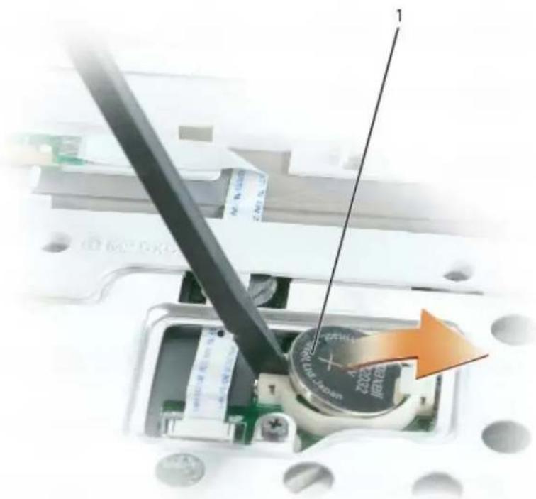
natural_image
Close-up of a mechanical component with a tool inserted, showing internal wiring and a magnified view (no readable text or symbols)1 coin-cell battery
Replacing the Coin-Cell Battery
CAUTION: Before you perform any of the procedures in this section, follow the safety instructions in the Product Information Guide.
NOTICE: To avoid electrostatic discharge, ground yourself by using a wrist grounding strap or by periodically touching an unpainted metal surface (such as the back panel) on the computer.
-
Follow the instructions in Preparing to Work Inside the Computer.
-
Follow the instructions in Removing the Coin-Cell Battery.
-
Insert the new battery into the circular socket with the positive side up, then push it into place.
-
Replace the keyboard (see Replacing the Keyboard).
-
Replace the hinge cover (see Replacing the Hinge Cover).
Back to Contents Page
Back to Contents Page
Wireless Mini PCI Card
Dell™ XPS M140 Service Manual
- Removing the Mini PCI Card
• Replacing the Mini PCI Card

NOTE: If you ordered the optional Mini PCI card at the same time that you ordered your computer, the card is already installed.
Removing the Mini PCI Card

CAUTION: Before you perform any of the procedures in this section, follow the safety instructions in the Product Information Guide.

NOTICE: To avoid electrostatic discharge, ground yourself by using a wrist grounding strap or by periodically touching an unpainted metal surface (such as the back panel) on the computer.
- Follow the instructions in Preparing to Work Inside the Computer.
- Loosen the two captive screws on the modem/Mini PCI/wireless cover, then remove the cover and set it aside.
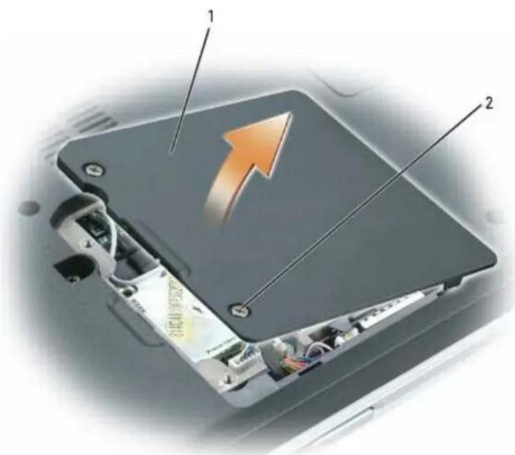
text_image
Diagram of an electronic device showing internal components with labeled parts and an upward arrow indicating growth or direction.1 modem/Mini PCI/wireless cover 2 captive screws (2)
- Disconnect the antenna cables from the Mini PCI card.
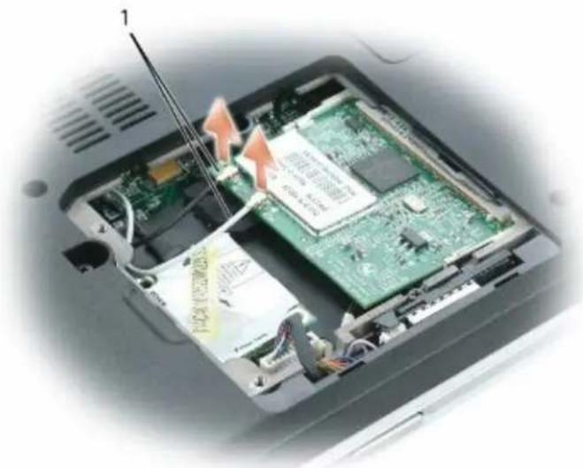
natural_image
Interior view of a computer case showing internal components and wiring, with no visible text or symbols.| 1 antenna cables |
NOTICE: To prevent damage to the Mini PCI card connector, do not use tools of any kind to spread the metal clips that secure the Mini PCI card.
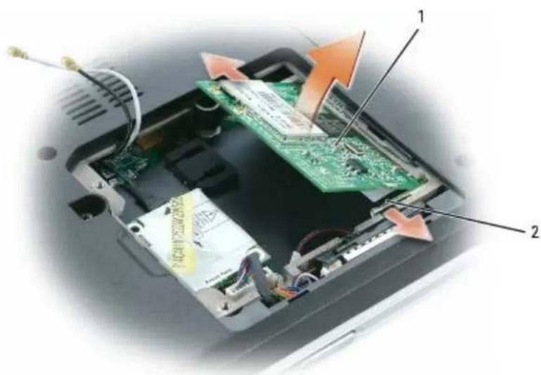
- Use your fingertips to carefully spread apart the metal clips securing each end of the Mini PCI card until the card pops up.
text_image
Diagram of an electronic device showing internal components with labeled parts and directional arrows indicating flow or movement.| 1 Mini PCI card 2 metal retention clips (2) |
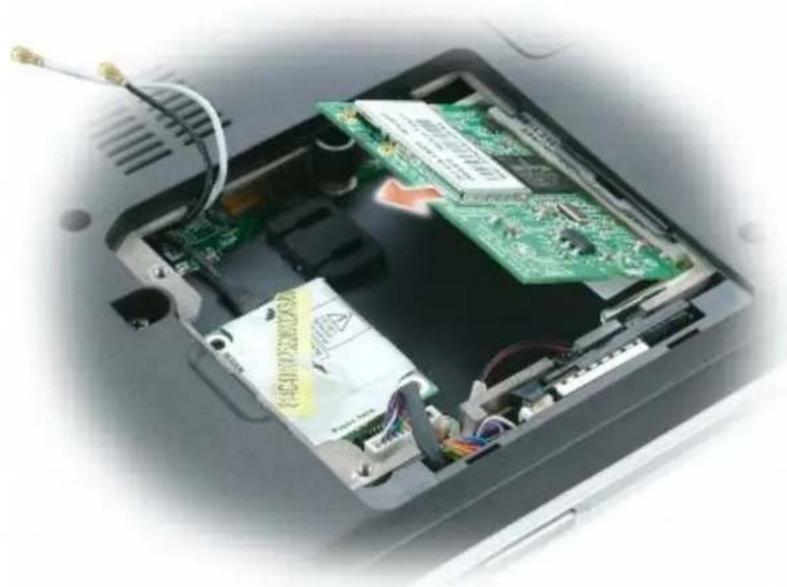
- Remove the Mini PCI card from the connector at a 45-degree angle.
natural_image
Interior view of an electronic device showing a green circuit board, power strip, and wiring (no visible text or symbols)Replacing the Mini PCI Card
CAUTION: Before you perform any of the procedures in this section, follow the safety instructions in the Product Information Guide.
NOTICE: To avoid electrostatic discharge, ground yourself by using a wrist grounding strap or by periodically touching an unpainted metal surface (such as the back panel) on the computer.
-
Follow the instructions in Preparing to Work Inside the Computer
-
Follow the instructions in Removing the Mini PCI Card, as applicable.
NOTICE: To avoid damaging the Mini PCI card, make sure the antenna cables are not under the card when you secure the card into place.
NOTICE: The edge connector is keyed to ensure correct insertion. If you feel resistance, check the connector and realign the card.
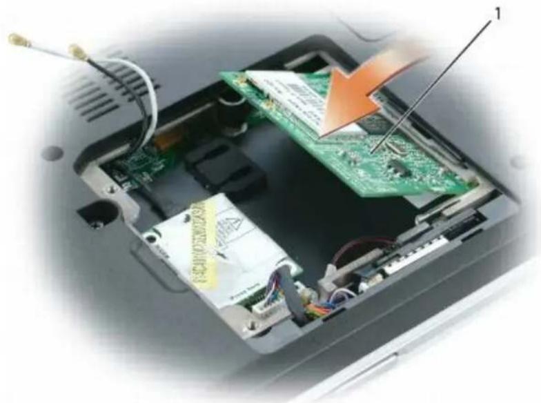
- Install the new Mini PCI card:
a. Align the notch in the Mini PCI card edge connector with the tab in the connector slot.
b. Slide the Mini PCI card firmly into the slot at a 45-degree angle, and then rotate the card down until it clicks into place. If you do not feel the click, remove the card and reinstall it.
natural_image
Interior view of an electronic device showing a green circuit board with a screwdriver inserted, and exposed wiring and components (no visible text or symbols)| 1 Mini PCI card |
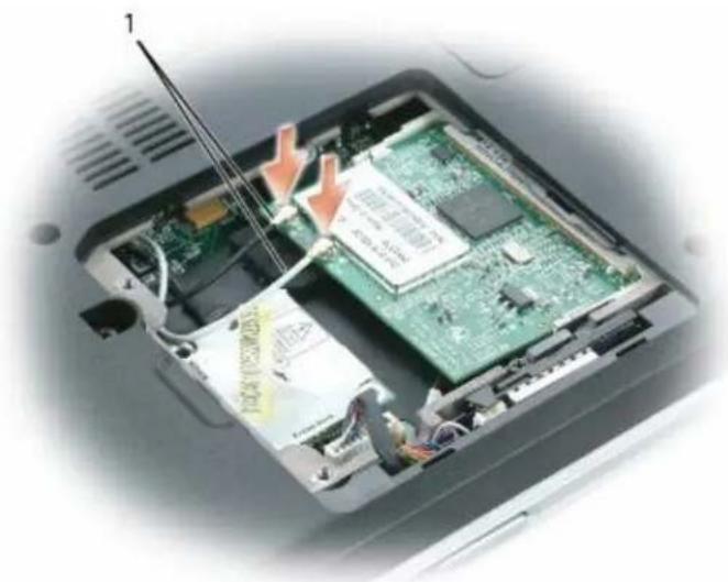
- Connect the antenna cables to the Mini PCI card. Make certain that the cable connectors snap securely into place.
natural_image
Interior view of a computer with visible circuit board and screwdriver (no text or symbols)| 1 antenna cables |
- Replace the modem/Mini PCI/wireless cover and tighten the screws.
Display Assembly and Display Latch
Dell™ XPS M140 Service Manual
- Display Assembly
Display Bezel
Display Panel
Display Latch
Display Assembly
Removing the Display Assembly
CAUTION: Before you perform any of the procedures in this section, follow the safety instructions in the Product Information Guide.
NOTICE: To avoid electrostatic discharge, ground yourself by using a wrist grounding strap or by periodically touching an unpainted metal surface (such as the back panel) on the computer.
- Follow the instructions in Preparing to Work Inside the Computer.
- Remove the hinge cover (see Removing the Hinge Cover).
- Remove the keyboard (see Removing the Keyboard).
- Open the display all the way (180 degrees) so that it rests flat against your work surface.
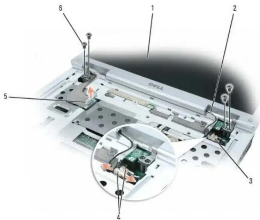
- Use the pull-tab to disconnect the display cable from the system board.
- Remove the Mini PCI antenna cables from the retaining clips on the base of the computer and pull apart the connectors.
- Remove the four M2.5 x 5-mm screws (two on each side) that connect the display assembly to the computer.
- Lift the display assembly straight out of the computer.
text_image
Laptop screen with labeled components and an inset close-up showing internal circuit board connections| 1 | display assembly 3 antenna | cable retaining clips 5 display cable | |
| 2 | Mini PCI antenna cables 4 | antenna cable connectors 6 M2.5 | x 5-mm screws (4) |
Replacing the Display Assembly

CAUTION: Before you perform any of the procedures in this section, follow the safety instructions in the Product Information Guide.

NOTICE: To avoid electrostatic discharge, ground yourself by using a wrist grounding strap or by periodically touching an unpainted metal surface (such as the back panel) on the computer.
- Follow the instructions in Preparing to Work Inside the Computer
- Follow the instructions in Removing the Display Assembly.
- Align the new display assembly over the screw holes in the base of the computer.
- Replace the four M2.5 x 5-mm screws (two on each side) to secure the display assembly to the base of the computer.
- Connect the Mini PCI antenna cable connectors and press the cables into the retaining clips on the base of the computer.
- Connect the display cable to the system board.
- Replace the keyboard (see Replacing the Keyboard).
- Replace the hinge cover (see Replacing the Hinge Cover).
Display Bezel
Removing the Display Bezel

CAUTION: Before you perform any of the procedures in this section, follow the safety instructions in the Product Information Guide.

NOTICE: To avoid electrostatic discharge, ground yourself by using a wrist grounding strap or by periodically touching an unpainted metal surface (such as the back panel) on the computer.
-
Follow the instructions in Preparing to Work Inside the Computer.
-
Remove the hinge cover (see Removing the Hinge Cover).
-
Remove the keyboard (see Removing the Keyboard).
-
Remove display assembly (see Removing the Display Assembly).
-
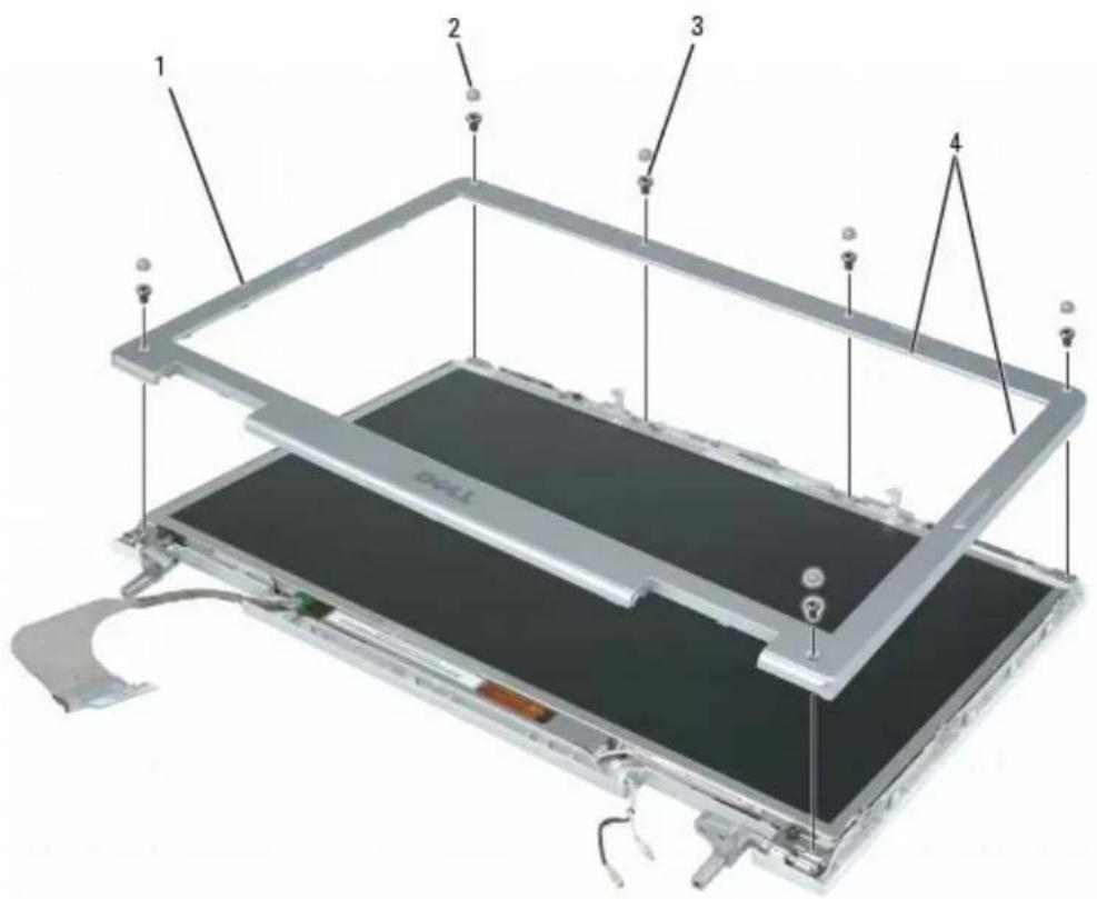
Use a plastic scribe to remove the six rubber bumpers from around the display assembly. It is not necessary to remove the oval bumpers located on the sides of the display.
-
Remove the six M2.5 x 5-mm screws from around the display assembly.

NOTICE: To avoid damaging the bezel, carefully separate the bezel from the display assembly by starting along the bottom of the display (near the Dell logo) and working around the edge of the display towards the release latch.
- Use your fingers to separate the bezel from the display assembly by lifting the inside edge of the bezel up and away from the center of the display assembly.
text_image
1 2 3 4| 1 | display bezel 2 rubber bumpers | (6) 3 M2.5 x 5-mm screws | (6) |
| 4 | inside edge of bezel |
Replacing the Display Bezel
CAUTION: Before you perform any of the procedures in this section, follow the safety instructions in the Product Information Guide.
NOTICE: To avoid electrostatic discharge, ground yourself by using a wrist grounding strap or by periodically touching an unpainted metal surface (such as the back panel) on the computer.
- Follow the instructions in Preparing to Work Inside the Computer
- Follow the instructions in Removing the Display Bezel.
- Starting near the hinges (near the Dell logo), use your fingers to snap the new bezel into place.
- Replace the six M2.5 x 5-mm screws to secure the bezel.
- Replace the six rubber bumpers to cover the screws.
- Replace the display assembly (see Replacing the Display Assembly).
- Replace the keyboard (see Replacing the Keyboard).
- Replace the hinge cover (see Replacing the Hinge Cover).
Display Panel
Removing the Display Panel
CAUTION: Before you perform any of the procedures in this section, follow the safety instructions in the Product Information Guide.
NOTICE: To avoid electrostatic discharge, ground yourself by using a wrist grounding strap or by periodically touching an unpainted metal surface (such as the back panel) on the computer.
- Follow the instructions in Preparing to Work Inside the Computer.
- Remove the hinge cover (see Removing the Hinge Cover).
- Remove the keyboard (see Removing the Keyboard).
- Remove display assembly (see Removing the Display Assembly).
- Remove the display bezel (see Removing the Display Bezel).
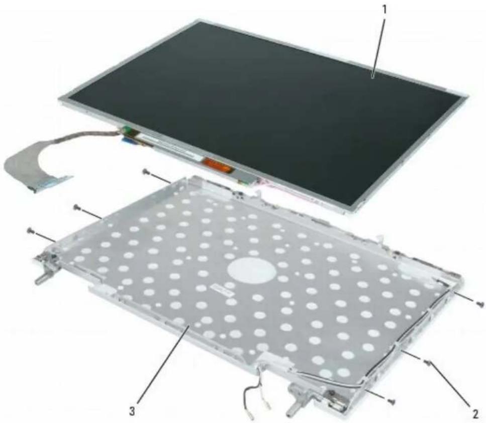
- Remove the six M2 x 3-mm screws (three on each side)securing the display panel to the display (top) cover.
- Gently lift the bottom of the display panel up, then slide the display panel forward to remove it from the display cover.
text_image
Exploded view diagram of an electronic device showing internal components with numbered labels1 display panel 2 M2 x 3-mm screws (6) 3 display cover
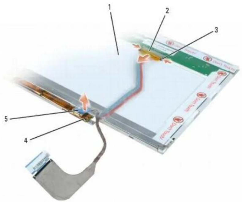
- Press inward on the metal clamps on both sides of the top flex-cable connector and gently pull to disconnect the top flex-cable connector from the display locking connector.
- Use the pull-tab to disconnect the bottom flex-cable connector from the inverter connector.
text_image
Labeled diagram of an electronic device showing components like battery, cable, and connector with numbered parts| 1 | back of display panel 3 metal | clamps 5 inverter connector | ||
| 2 | top flex-cable connector 4 bottom | flex-cable connector |
Replacing the Display Panel
CAUTION: Before you perform any of the procedures in this section, follow the safety instructions in the Product Information Guide.
NOTICE: To avoid electrostatic discharge, ground yourself by using a wrist grounding strap or by periodically touching an unpainted metal surface (such as the back panel) on the computer.
- Follow the instructions in Preparing to Work Inside the Computer
- Follow the instructions in Removing the Display Panel.
- Connect the top flex-cable connector to the display locking connector on the new display panel.
- Connect the bottom flex-cable connector to the inverter connector.
NOTICE: To avoid damaging the display cover and/or the display panel, ensure that the guide posts at the top of the display panel are properly aligned with the corresponding notches on the display cover.
- Gently place the display panel inside the display cover.
- Replace the six M2 x 3-mm screws (three on each side) to secure the display panel to the display cover.
- Replace the display bezel (see Replacing the Display Bezel).
- Replace display assembly (see Replacing the Display Assembly).
- Replace the keyboard (see Replacing the Keyboard).
- Replace the hinge cover (see Replacing the Hinge Cover).
Display Latch
Removing the Display Latch
CAUTION: Before you perform any of the procedures in this section, follow the safety instructions in the Product Information Guide.
NOTICE: To avoid electrostatic discharge, ground yourself by using a wrist grounding strap or by periodically touching an unpainted metal surface (such as the back panel) on the computer.
-
Follow the instructions in Preparing to Work Inside the Computer.
-
Remove the hinge cover (see Removing the Hinge Cover).
-
Remove the keyboard (see Removing the Keyboard).
-
Remove display assembly (see Removing the Display Assembly).
-
Remove the display bezel (see Removing the Display Bezel).
NOTICE: The display latch spring is not physically connected to the latch assembly. Exercise care that the spring is not lost.
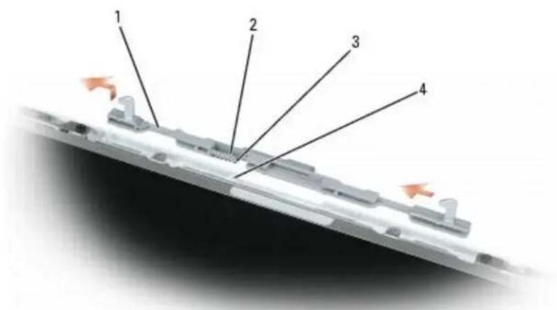
- Slightly rotate the left side of the display latch assembly away from the center of the top cover, then lift up and to the left to remove the latch assembly.
text_image
1 2 3 4| 1 display latch assembly 2 latch spring 3 guide | post | ||
| 4 guide post slot |
Replacing the Display Latch
CAUTION: Before you perform any of the procedures in this section, follow the safety instructions in the Product Information Guide.
NOTICE: To avoid electrostatic discharge, ground yourself by using a wrist grounding strap or by periodically touching an unpainted metal surface (such as the back panel) on the computer.
-
Follow the instructions in Preparing to Work Inside the Computer
-
Follow the instructions in Removing the Display Latch.
NOTICE: Before replacing the display latch assembly, ensure that the latch spring is properly aligned on the guide post.
- Insert the guide post of the new display latch assembly (with spring) into the slot on the display (top) cover.

NOTE: When the guide post is in position, the display latch assembly may automatically snap into place.
- Press the remainder of the display latch assembly into place, as needed.
- Replace the display bezel (see Replacing the Display Bezel).
- Replace display assembly (see Replacing the Display Assembly).
- Replace the keyboard (see Replacing the Keyboard).
- Replace the hinge cover (see Replacing the Hinge Cover).
Back to Contents Page
Palm Rest
Dell™ XPS M140 Service Manual
Removing the Palm Rest
Replacing the Palm Rest
Removing the Palm Rest
CAUTION: Before you perform any of the procedures in this section, follow the safety instructions in the Product Information Guide.
NOTICE: To avoid electrostatic discharge, ground yourself by using a wrist grounding strap or by periodically touching an unpainted metal surface (such as the back panel) on the computer.
-
Follow the instructions in Preparing to Work Inside the Computer.
-
Remove the optical drive (see Removing the Optical Drive).
-
Remove the hinge cover (see Removing the Hinge Cover).
-
Remove the keyboard (see Removing the Keyboard).
-
Remove the display assembly (see Removing the Display Assembly).
-
Remove the microprocessor thermal-cooling assembly (see Removing the Microprocessor Thermal-Cooling Assembly).
-
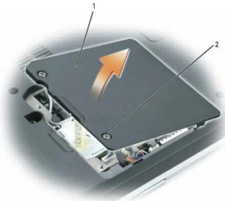
Loosen the two captive screws on the modem/Mini PCI/wireless cover, then remove the cover and set it aside.
text_image
Diagram of an electronic device showing internal components with labeled parts and an orange arrow indicating direction1 modem/Mini PCI/wireless cover 2 captive screws (2)
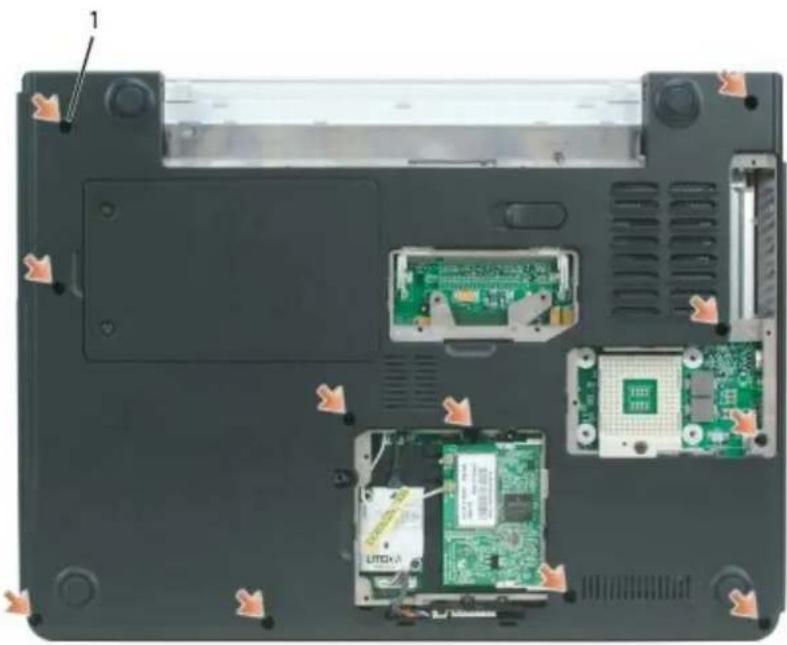
- Remove the eleven M2.5 x 8-mm screws securing the palm rest from the bottom of the computer.
natural_image
Laptop interior showing internal components including CPU socket, circuit board, and drive slots (no text or symbols visible)1 M2.5 x 8-mm screws (11)
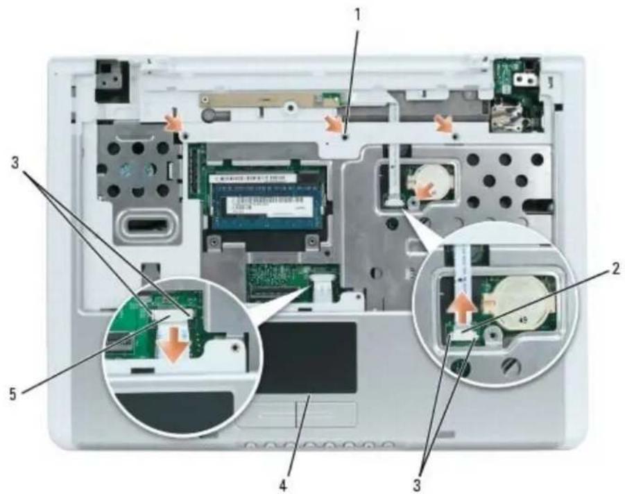
- Turn the computer over and remove the four M2.5 x 5-mm screws securing the top of the palm rest.

NOTICE: Release the locking tabs on both sides of the system board connector before attempting to remove the touch pad or LED cable. Failure to release the locking tabs could result in damage to the cable and/or the cable
connector.
- Disconnect the touch pad cable.
Use a plastic scribe to release the locking clips on both sides of the system board connector, and then gently pull to disconnect the touch pad connector from the system board connector.
- Disconnect the LED board cable.
Use a plastic scribe to release the locking clips on both sides of the system board connector, and then gently pull to disconnect the LED board connector from the system board connector.
text_image
Laptop interior diagram with numbered components and close-ups of internal electronics, highlighting circuit boards and memory drives.| 1 | M2.5 x 5-mm screws (4) 3 locking | clips | 5 touch pad connector | ||
| 2 | LED board connector 4 palm rest |
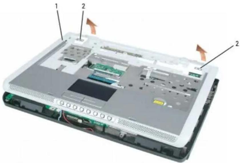
- Moving from left to right, carefully lift the palm rest along the rear edge, near the hinge brackets, then rotate the palmrest forward to remove it from the computer.
text_image
Laptop interior diagram with labeled components and directional arrows indicating movement or flow1 palmrest 2 hinge brackets
Replacing the Palm Rest
CAUTION: Before you perform any of the procedures in this section, follow the safety instructions in the Product Information Guide.
NOTICE: To avoid electrostatic discharge, ground yourself by using a wrist grounding strap or by periodically touching an unpainted metal surface (such as the back panel) on the computer.
- Follow the instructions in Preparing to Work Inside the Computer
- Follow the instructions in Removing the Palm Rest.
- Align the new palm rest with the base of the computer, and then snap the palm rest into place.
NOTICE: To prevent damage to the cables or the cable connectors, ensure that the locking clips on both sides of each system board connector are firmly seated and the cables are secure.
- Connect the touch pad cable to the system board.
- Connect the LED board cable to the system board.
- Replace the four M2.5 x 5-mm screws in the top of the palm rest.
- Turn the computer over and replace the eleven M2.5 x 8-mm screws in the bottom of the computer to secure the palm rest.
- Replace the microprocessor thermal-cooling assembly (see Replacing the Microprocessor Thermal-Cooling Assembly).
-
Replace the modem/Mini PCI/wireless cover and tighten the screws.
-
Replace the display assembly (see Replacing the Display Assembly).
- Replace the keyboard (see Replacing the Keyboard).
- Replace the hinge cover (see Replacing the Hinge Cover).
- Replace the optical drive (see Replacing the Optical Drive).
Back to Contents Page
Microprocessor Thermal-Cooling Assembly
Dell™ XPS M140 Service Manual
- Removing the Microprocessor Thermal-Cooling Assembly
- Replacing the Microprocessor Thermal-Cooling Assembly
Removing the Microprocessor Thermal-Cooling Assembly

CAUTION: Before you perform any of the procedures in this section, follow the safety instructions in the Product Information Guide.

NOTICE: To avoid electrostatic discharge, ground yourself by using a wrist grounding strap or by periodically touching an unpainted metal surface (such as the back panel) on the computer.
- Follow the instructions in Preparing to Work Inside the Computer.
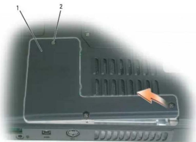
- Loosen the three captive screws securing the microprocessor module cover, then remove the cover and set it aside.
text_image
Labeled diagram of a computer keyboard showing two components and an orange arrow pointing to the right panel.1 microprocessor module cover 2 captive screws (3)
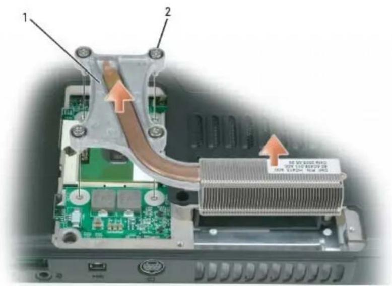
- Loosen the four captive screws securing the microprocessor thermal-cooling assembly to the system board, then carefully lift the assembly straight out of the computer.
text_image
1 2 热泵 0.0000 GB 50% 132 GB/27 GB 50% 132GB GB 50% 2851 microprocessor thermal-cooling assembly 2 captive screws (4)
Replacing the Microprocessor Thermal-Cooling Assembly
CAUTION: Before you perform any of the procedures in this section, follow the safety instructions in the Product Information Guide.
NOTICE: To avoid electrostatic discharge, ground yourself by using a wrist grounding strap or by periodically touching an unpainted metal surface (such as the back panel) on the computer.
- Follow the instructions in Preparing to Work Inside the Computer
- Follow the instructions in Removing the Microprocessor Thermal-Cooling Assembly.
- Align the four captive screws on the new microprocessor thermal-cooling assembly with the screw holes on the system board.
- Tighten the four captive screws in the order that they are numbered to secure the microprocessor thermal-cooling assembly to the system board.
- Replace the microprocessor module cover.
Back to Contents Page
Fan
Dell™ XPS M140 Service Manual
Removing the Fan
Replacing the Fan
Removing the Fan
CAUTION: Before you perform any of the procedures in this section, follow the safety instructions in the Product Information Guide.
NOTICE: To avoid electrostatic discharge, ground yourself by using a wrist grounding strap or by periodically touching an unpainted metal surface (such as the back panel) on the computer.
- Follow the instructions in Preparing to Work Inside the Computer.
- Remove the optical drive (see Removing the Optical Drive).
- Remove the hinge cover (see Removing the Hinge Cover).
- Remove the keyboard (see Removing the Keyboard).
- Remove the display assembly (see Removing the Display Assembly).
- Remove the palm rest (see Removing the Palm Rest).
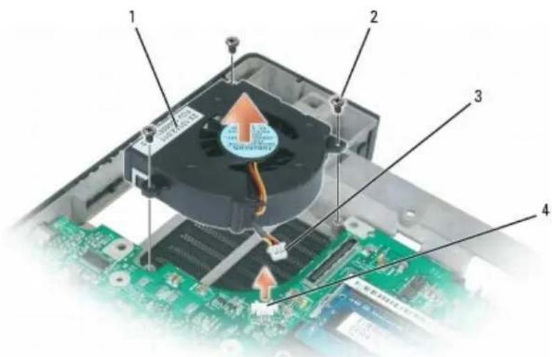
- Remove the three M2.5 x 5-mm screws securing the fan to the base of the computer.
- Disconnect the fan connector from the system board connector.
- Lift the fan out of the computer.
text_image
Diagram of an electronic device showing labeled components including a fan, CPU socket, and motherboard with Chinese annotations.| 1 | fan 2 M2.5 x 5-mm screws (3) | 3 | fan connector | ||
| 4 | system board connector |
Replacing the Fan
CAUTION: Before you perform any of the procedures in this section, follow the safety instructions in the Product Information Guide.
NOTICE: To avoid electrostatic discharge, ground yourself by using a wrist grounding strap or by periodically touching an unpainted metal surface (such as the back panel) on the computer.
- Follow the instructions in Preparing to Work Inside the Computer
- Follow the instructions in Removing the Fan.
- Align the three screw holes on the new fan with the corresponding screw holes on the system board.
- Replace the three M2.5 x 5-mm screws to secure the fan to the base of the computer.
- Connect the fan connector to the system board connector.
- Replace the palm rest (see Replacing the Palm Rest).
- Replace the display assembly (see Replacing the Display Assembly).
- Replace the keyboard (see Replacing the Keyboard).
- Replace the hinge cover (see Replacing the Hinge Cover).
- Replace the optical drive (see Replacing the Optical Drive).
Back to Contents Page
Microprocessor Module
Dell™ XPS M140 Service Manual
Removing the Microprocessor Module
Replacing the Microprocessor Module
Removing the Microprocessor Module
CAUTION: Before you perform any of the procedures in this section, follow the safety instructions in the Product Information Guide.
NOTICE: To avoid electrostatic discharge, ground yourself by using a wrist grounding strap or by periodically touching an unpainted metal surface (such as the back panel) on the computer.
NOTICE: Handle the microprocessor module with care. Hold the microprocessor module by its edges and do not touch the processor die (the small chip in the center of the module).
-
Follow the instructions in Preparing to Work Inside the Computer.
-
Loosen the three captive screws securing the microprocessor module cover, then remove the cover and set it aside.
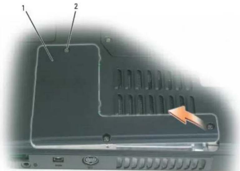
text_image
Labeled diagram of a computer rear panel showing two components with an orange arrow pointing to one component.1 microprocessor module cover 2 captive screws (3)
NOTICE: To ensure maximum cooling for the microprocessor, do not touch the heat transfer areas on the microprocessor thermal-cooling assembly. Oils in your skin can reduce the heat transfer capability of the
thermal pads.
- Remove the microprocessor thermal-cooling assembly (see Removing the Microprocessor Thermal-Cooling Assembly).
NOTICE: To avoid damaging the microprocessor, hold the screwdriver so that it is perpendicular to the microprocessor module when turning the cam screw.
- To loosen the ZIF-socket cam lock, use a small, flat-blade screwdriver to rotate the ZIF-socket cam screw counterclockwise until it comes to the cam stop.
NOTE: The ZIF-socket cam screw secures the microprocessor module to the system board.
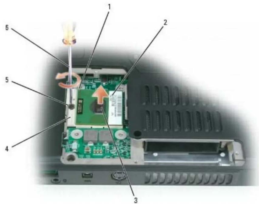
text_image
Labeled diagram of an electronic device showing internal components and a screwdriver inserted into a circuit board.| 1 | microprocessor pin-1 corner 3 processor | die 5 ZIF-socket | cam | screw |
| 2 | microprocessor module 4 ZIF socket | 6 screwdriver |
NOTICE: When removing the microprocessor module, pull the module straight up and out of the ZIF socket. Exercise care not to bend the pins on the microprocessor module.
- Lift the microprocessor module straight up and out of the ZIF socket.
Replacing the Microprocessor Module
CAUTION: Before you perform any of the procedures in this section, follow the safety instructions in the Product Information Guide.
NOTICE: To avoid electrostatic discharge, ground yourself by using a wrist grounding strap or by periodically touching an unpainted metal surface (such as the back panel) on the computer.
- Follow the instructions in Preparing to Work Inside the Computer
NOTICE: Handle the microprocessor module with care. Hold the microprocessor module by its edges and do not touch the processor die (the small chip in the center of the module).
- Follow the instructions in Removing the Microprocessor Module.
NOTICE: Ensure that the cam lock is in the fully open position before seating the microprocessor module. Seating the microprocessor module properly in the ZIF socket does not require force. A microprocessor module that is not properly seated can result in an intermittent connection or permanent damage to the microprocessor and ZIF socket.
- Align the pin-1 corner of the new microprocessor module with the pin-1 corner of the ZIF socket, and insert the microprocessor module.
NOTE: The pin-1 corner of the microprocessor module has a triangle that aligns with the triangle on the pin-1 corner of the ZIF socket.
NOTE: Gently press down on the substrate on which the processor die is mounted to ensure the microprocessor module is properly seated.
When the microprocessor module is properly seated, all four corners of the module are aligned at the same height. If one or more corners of the module is higher than the others, the module is not properly seated.
NOTICE: To avoid damaging the microprocessor, hold the screwdriver so that it is perpendicular to the microprocessor module when turning the cam screw.
-
Tighten the ZIF-socket cam lock by turning the cam screw clockwise to secure the microprocessor module to the system board.
-
Replace the microprocessor thermal-cooling assembly (see Replacing the Microprocessor Thermal-Cooling Assembly).
-
Replace the microprocessor module cover.
-
Update the BIOS using a flash BIOS update program floppy disk or CD. For instructions on how to flash the BIOS, see BIOS Updates.
Speakers
Dell™ XPS M140 Service Manual
Removing the Speakers
Replacing the Speakers
Removing the Speakers
CAUTION: Before you perform any of the procedures in this section, follow the safety instructions in the Product Information Guide.
NOTICE: To avoid electrostatic discharge, ground yourself by using a wrist grounding strap or by periodically touching an unpainted metal surface (such as the back panel) on the computer.
-
Follow the instructions in Preparing to Work Inside the Computer.
-
Remove the optical drive (see Removing the Optical Drive).
-
Remove the hinge cover (see Removing the Hinge Cover).
-
Remove the keyboard (see Removing the Keyboard).
-
Remove the display assembly (see Removing the Display Assembly).
-
Remove the microprocessor thermal-cooling assembly (see Removing the Microprocessor Thermal-Cooling Assembly).
-
Remove the palmrest (see Removing the Palm Rest).
NOTICE: Exercise care when removing and handling the speakers.
- Disconnect the speaker connector from the system board connector.
- Remove the three M2.5 x 5-mm screws securing the speakers to the base of the computer.
NOTE: There are two screws securing the left speaker and one screw securing the right speaker.
- Lift the speakers straight up and out of the computer.
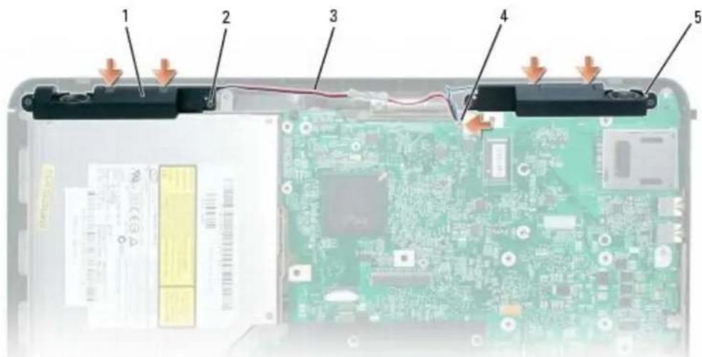
text_image
Laptop screen showing internal components with numbered labels pointing to battery pack, circuit board, and cable| 1 | speakers (2) 3 speaker cable 5 guide post slots (4) | ||
| 2 | M2.5 x 5-mm screws (3) 4 speaker connector |
Replacing the Speakers
CAUTION: Before you perform any of the procedures in this section, follow the safety instructions in the Product Information Guide.
NOTICE: To avoid electrostatic discharge, ground yourself by using a wrist grounding strap or by periodically touching an unpainted metal surface (such as the back panel) on the computer.
- Follow the instructions in Preparing to Work Inside the Computer.
- Follow the instructions in Removing the Speakers.
NOTICE: Exercise care when handling or replacing the speakers.
- Place each of the new speakers in the appropriate speaker slot.
NOTE: For proper placement, align the slots on the speakers with the screw-hole guide posts on the base of the computer.
-
Replace the three M2.5 x 5-mm screws to secure the speakers to the base of the computer.
-
Connect the speaker cable to the system board.
-
Replace the palmrest (see Replacing the Palm Rest).
-
Replace the microprocessor thermal-cooling assembly (see Replacing the Microprocessor Thermal-Cooling Assembly).
-
Replace the display assembly (see Replacing the Display Assembly).
- Replace the keyboard (see Replacing the Keyboard).
- Replace the hinge cover (see Replacing the Hinge Cover).
- Replace the optical drive (see Replacing the Optical Drive).
Back to Contents Page
System Board
Dell™ XPS M140 Service Manual
- Removing the System Board
Replacing the System Board
Removing the System Board
CAUTION: Before you perform any of the procedures in this section, follow the safety instructions in the Product Information Guide.
NOTICE: To avoid electrostatic discharge, ground yourself by using a wrist grounding strap or by periodically touching an unpainted metal surface (such as the back panel) on the computer.
The system board's BIOS chip contains the Service Tag, which is also visible on a barcode label on the bottom of the computer. The replacement kit for the system board includes a CD that provides a utility for transferring the Service Tag to the replacement system board.
- Follow the instructions in Preparing to Work Inside the Computer.
- Remove the hard drive (see Removing the Hard Drive).
- Remove the optical drive (see Removing the Optical Drive).
- Remove the Mini PCI card, if applicable (see Removing the Mini PCI Card).
- Remove the modem, if applicable (see Removing the Modem).
- Remove the Bluetooth module, if applicable (see Removing the Bluetooth Module).
- Disconnect the cable for the Bluetooth module from the system board.
- Remove the hinge cover (see Removing the Hinge Cover).
- Remove the keyboard (see Removing the Keyboard).
- Remove the display assembly (see Removing the Display Assembly).
- Remove all memory modules (see Removing a Memory Module).
-
Remove the microprocessor module (see Removing the Microprocessor Module).
-
Remove the micropressor thermal-cooling assembly (see Removing the Microprocessor Thermal-Cooling Assembly).
-
Remove the palmrest (see Removing the Palm Rest).
- Remove the two M2 x 3-mm screws securing the system board from the bottom of the computer.
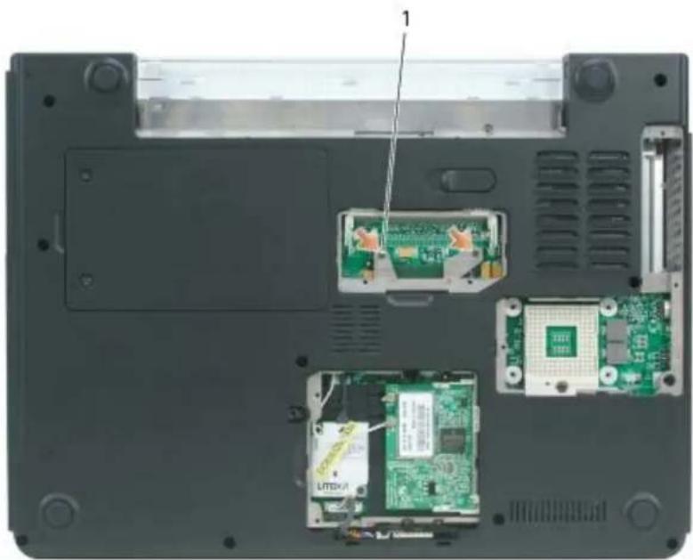
natural_image
Laptop interior showing internal components including CPU socket, circuit board, and ventilation slots (no text or symbols visible)1 M2 x 3-mm screws (2)
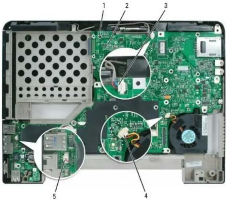
- Turn the computer over so that the bottom is facing down and remove the M2.5 x 5-mm screw securing the system board.
- Disconnect the fan cable from the system board.
- Disconnect the speaker cable from the system board.
- Disconnect the modem cable from the system board.
text_image
Laptop motherboard photo with numbered component annotations showing circuit board, CPU socket, and power connections| 1 | M2.5 x 5-mm screw 3 speaker | connector 5 modem connector | ||
| 2 | system board 4 fan connector |
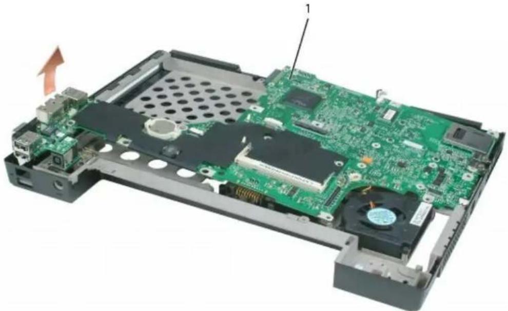
- With the rear of the computer facing you, gently lift the system board assembly from the left side, then slide the system board assembly to the left and lift up on the right side to raise the assembly out of the computer.

NOTE: It may be necessary to press outward slightly on the plastic around the connectors on the left side of the computer to lift the system board and remove it.
natural_image
Interior view of a computer motherboard showing green circuit board, CPU socket, and drive components (no text or symbols visible)| 1 system board |
Replacing the System Board
CAUTION: Before you perform any of the procedures in this section, follow the safety instructions in the Product Information Guide.
NOTICE: To avoid electrostatic discharge, ground yourself by using a wrist grounding strap or by periodically touching an unpainted metal surface (such as the back panel) on the computer.
- Follow the instructions in Preparing to Work Inside the Computer.
- Follow the instructions in Removing the System Board.
- For replacement of the system board, perform the steps in Removing the System Board in reverse order.
NOTICE: Before turning on the computer, replace all screws and ensure that no stray screws remain inside the computer. Failure to do so may result in damage to the computer.
- Turn on the computer.
NOTE: After replacing the system board, enter the computer's alpha-numeric Service Tag into the BIOS of the replacement system board.
- Insert the floppy disk or CD that accompanied the replacement system board into the appropriate drive. Follow the instructions that appear on the screen.
BIOS Updates
Dell™ XPS M 140 Service Manual
- Flashing the BIOS
Flashing the BIOS

NOTICE: Plug the AC adapter into a known-good power source to prevent a loss of power. Failure to do so may cause damage to the computer.
- Ensure that the AC adapter is plugged in and that the main battery is properly installed.
- Turn on the computer.

NOTE: If you use a BIOS update program CD to flash the BIOS, set up the computer to boot from a CD before inserting the CD.
- Insert the BIOS update program floppy disk or CD, then reboot the computer.

NOTICE: Do not interrupt the flash BIOS process once it begins. Interrupting the process may cause damage to the computer.
Follow the instructions that appear on the screen. The computer continues to boot and updates the new BIOS. When the flash update is complete, the computer will automatically reboot.
- Press
during POST to enter the system setup program. - Press
and to reset the computer defaults. - Press
, select Save changes and reboot, and press to save configuration changes. - Remove the flash BIOS update program floppy disk or CD from the drive and restart the computer.
Back to Contents Page
Pin Assignments for I/O Connectors
Dell™ XPS M140 Service Manual
USB Connector
Video Connector
S-Video TV-Out Connector
IEEE 1394 Connector
USB Connector
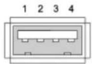
| Pin Signal |
| 1 USB5V+ |
| 2 USBP- |
| 3 USBP+ |
| 4 GND |
Video Connector
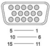
| Pin Signal Pin Signal | |||
| 1 CRT_R 9 5V+ | |||
| 2 CRT_G 10 GND | |||
| 3 CRT_B 11 MONITOR_DETECT- | |||
| 4 NC 12 DDC_DATA | |||
| 5 GND 13 CRT_HS | |||
| 6 GND 14 CRT_VS | |||
| 7 GND 15 DDC_CLK | |||
| 8 GND | |||
S-Video TV-Out Connector
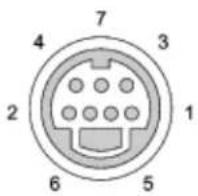
| S-Video | |
| Pin | Signal |
| 1 | GND |
| 2 | GND |
| 3 | DLUMA-L |
| 4 | DCRMA-L |
| Composite Video | |
| Pin Signal | |
| 5 | NC |
| 6 DCMPS-L | |
| 7 GND | |
IEEE 1394 Connector
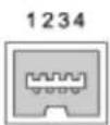
| Pin | Signal |
| 1 TPB- |
| 2 TPB+ |
| 3 TPA- |
| 4 TPA+ |
Back to Contents Page