Home Run - Treadmills Skandika - Free user manual and instructions
Find the device manual for free Home Run Skandika in PDF.


| Product Type | Treadmill |
| Brand | Skandika |
| Model | Home Run |
| Special Edition | Joey Kelly |
| Maximum User Weight | 120 kg / 265 lbs |
| Power Supply | 110V or 220V (depending on model) |
| Display Functions | Time, Speed, Distance, Calories, Pulse |
| Speed Adjustment | Yes, via +/− buttons |
| Safety Key | Yes, emergency stop |
| Folding Design | Yes, folds for storage |
| Transport Wheels | Yes, 2 wheels |
| Heart Rate Monitoring | Hand pulse sensors |
| Lubrication Interval | Every 6 months or as needed |
| Running Belt Adjustment | Yes, centering and tension using Allen wrench |
| Leveling Feet | 8 levelers for stability |
| Warranty | 24 months from delivery to end user |
| Intended Use | Home use only |
| Manual Languages | DE, EN (other languages available via translation service) |
Frequently Asked Questions - Home Run Skandika
User questions about Home Run Skandika
0 question about this device. Answer the ones you know or ask your own.
Ask a new question about this device
Download the instructions for your Treadmills in PDF format for free! Find your manual Home Run - Skandika and take your electronic device back in hand. On this page are published all the documents necessary for the use of your device. Home Run by Skandika.
USER MANUAL Home Run Skandika
natural_image
Exterior view of three Skendika HomeRun devices (black, red, white) with circular cutouts and control knobs, shown against a dark background (no text or symbols on the devices themselves)natural_image
Portrait of a man holding a gold medal, wearing a white jacket and cap (no visible text or symbols)SPECIAL EDITION JOEY KELLY
Joeg Helly
WILLKOMMEN
Bevor Sie beginnen
AUFBAUANLEITUNG
natural_image
Technical line drawing of a mechanical housing component (no text or symbols)AUFBAUANLEITUNG
Schmieranweisungen
natural_image
Diagram showing two mechanical linkage mechanisms with rotational arrows indicating motion (no text or symbols)natural_image
Diagram showing two mechanical components with curved arrows indicating motion, labeled Abb.12 (no text or symbols on the diagram itself)Einschalten
Congratulations on the purchase of your Skandika Home Run!
The Skandika range of training equipment is a high quality and durable product line which appeals to users with top of the line materials and professional workmanship. Skandika equipment is very well suited for fitness training in your own home.
Safety notes
Exercise can present a health risk. Consult a physician before beginning any exercise program with this equipment. If you feel faint or dizzy, immediately discontinue use of this equipment. Serious bodily injury can occur if this equipment is not assembled and used correctly. Serious bodily injury can also occur if all instructions are not followed.
Keep children and pets away from equipment when in use. Always make sure all bolts and nuts are tightened prior to each use. Follow all safety instructions in this manual.
CAUTION: THE MAXIMUM LOAD SHOULD NOT EXCEED 120KG / 265LBS FOR THIS DEVICE.
- Read all warnings posted on the equipment.
- Read this manual and follow it carefully before using the equipment. Make sure that it is properly assembled before use.
- Keep children and pets away from the equipment. Do not allow children and pets to use or play on the equipment. Always keep children and pets away from the equipment when it is in use.
• It is recommended that you place this exercise equipment on an equipment mat. - Operate the equipment on a solid and level surface. Do not position the equipment on loose rugs or uneven surfaces.
- Inspect the equipment for worn or loose components prior to each use.
- Tighten / replace any loose or worn components prior to using the equipment.
- Consult a physician prior to commencing an exercise program. If, at any time during exercise, you feel faint, dizzy, or experience pain, stop and consult your physician.
- Always choose the workout which best fits your physical strength and flexibility level. Know your limits and train within them. Always use common sense when exercising.
- Hold on to handrails when adjusting speed, or other controls.
- Wear proper exercise clothing and shoes for your workout and avoid loose clothing. Never exercise in bare feet or socks; always wear correct footwear, such as running, walking, or cross-training shoes.
- Use care when getting on or off the treadmill. When stepping on the running belt, always grasp the handrail when stepping and keep the initial speed at or below 1 kilometer per hour (kph) or 1 mile per hour (mph). Never step off the treadmill while the running belt is moving.
- Be careful to maintain your balance while using, mounting, dismounting, or assembling the equipment loss of balance may result in serious injuries.
• Never insert any objects or body parts into any opening.
• Always unplug the treadmill before cleaning and/or maintaining.
• The equipment should not be used by persons weighing over 265 pounds / 120 kgs.
• The equipment should be used by only one person at a time. - Maintenance: Defective components should be replaced immediately by an authorized service. Do not use the equipment until all repairs have completed thoroughly.
- Make sure that adequate space is available for access to and passage around the equipment; keep at least a distance of 1 meter from any obstruction object while using the machine.
WARNING: Before starting any exercise or conditioning program you should consult with your personal physician to see if you require a complete physical exam. This is especially important if you are over the age of 35, have never exercised before, are pregnant, or suffer from any illness.
TABLE OF CONTENTS
Table of contents
Folding / Unfolding instructions 16
Power cord instructions....17
Level adjustment 18
Moving the treadmill 18
Changing to table/bench....18
Lubrication instructions....19
Running belt adjustment....19
The safety key 21
Console operation 22
Exploded drawing....23
Part list....24
Guarantee conditions 25
Visit our website for further information www.skandika.com
Scan the QR code with your smartphone

ASSEMBLY INSTRUCTIONS
Unfolding instructions
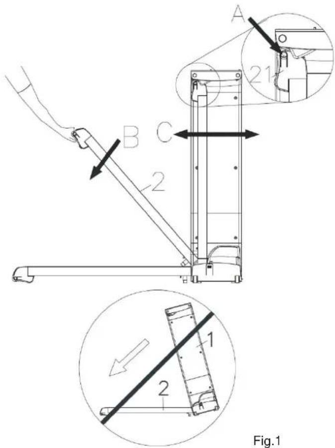
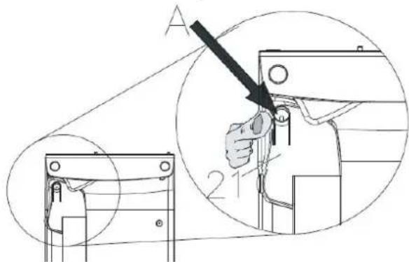
A. Gently press the button (A) located on the right upper side of Right Rear EndCap (21) as the drawing shown below. The Deck (2) will start to descend. Keep holding the Deck (2) with two hands until hearing the "click" sound to make sure the deck has fully descended to the floor.
B. In order to prevent the danger of the Main Frame (1) falls off like FIG 1 shown, gently move/shake the Main Frame (1) front and back to double make sure the Deck (2) has totally locked and fully descended to the floor.
Folding instructions
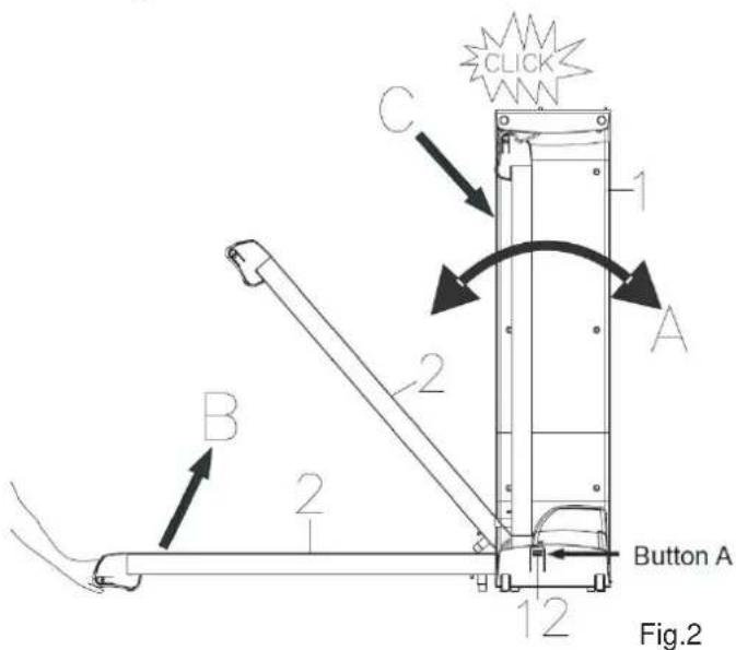
A. Press STOP on the console and wait until the belt has fully stopped. B. Gently press the button (A) located on the right bottom side of Upper Motor Cover (12).
NOTE: If the item places on an uneven surface, will make the button (A) hard to press, to make the button (A) easy to press, gently shake the Main Frame (1) front and back.
C. Keep pressing the button (A) while using the other hand to fold up the Deck (2) from B to C position until hearing the "click" sound to make sure the deck has fully locked to the Main Frame (1).
ASSEMBLY INSTRUCTIONS
Power cord operation instructions
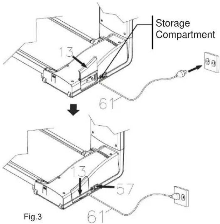
A. Open the Storage Door (13).
B. Unwrap the Power Cord (61) from the unit's storage compartment.
C. Before plugging the Power Cord (61) into the electrical outlet, make sure that the supply voltage matches the voltage information stated on the type label (located on front of the item).
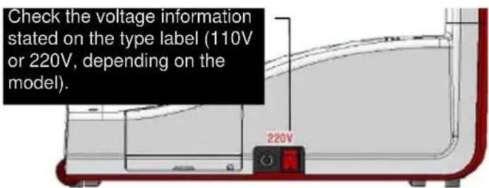
D. Connect the Power Cord (61) to the electrical outlet, then close the Storage Door (13). To switch on the console, turn on the Main Power Switch (57) located at the front of the unit, near the power cord.
Power cord storage instructions
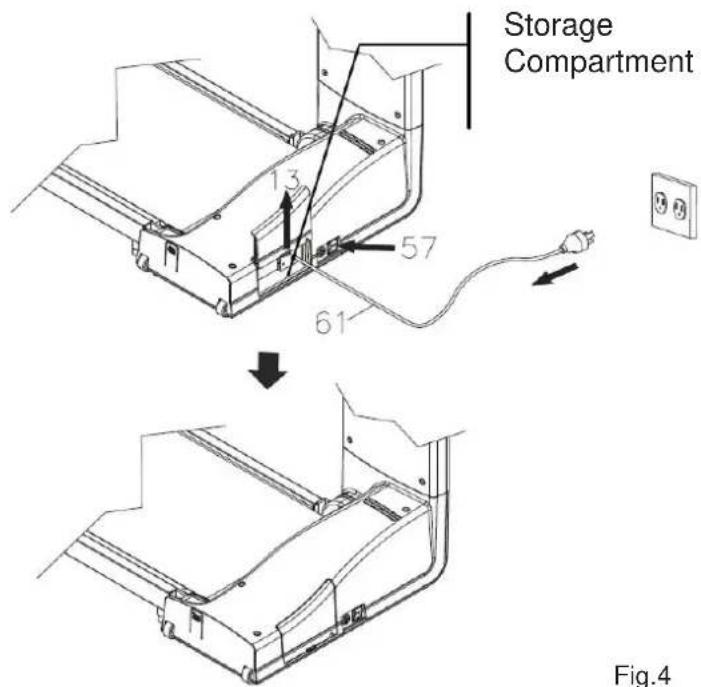
To store power cord in a safe storage compartment, please follow these steps:
A. Turn off the Main Power Switch (57) and unplug the Power Cord (61) from the electrical outlet.
B. Neatly wrap the Power Cord (61) around the storage compartment and gently close the Storage Door (13).
Fig.4
ASSEMBLY INSTRUCTIONS
Level adjustment instructions
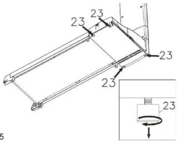
Fig.5
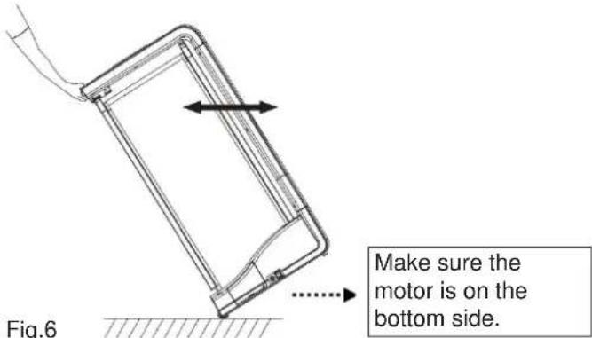
Moving the treadmill instructions
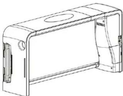
Changing to table/bench instructions
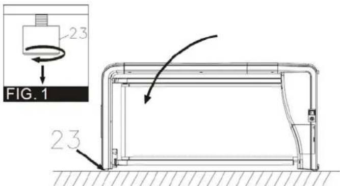
Fig.7
A. After placing the equipment at the intended location for use, make sure the item on the floor. To level the item, please follow the following steps.
B. Tip the item to the left/right. You will then see the Levelers (23). To make the Levelers (23) rest firmly on the floor, turn the Levelers (23) clockwise until the Levelers (23) touch the floor completely. The device should be positioned completely leveled - if not, repeat the above process.
A. Turn the power switch off.
B. Unplug the power cord.
C. Fold the treadmill and make sure the lock is secured.
D. Make sure the motor is on the bottom side.
E. Simply roll the treadmill with two transportation wheels to the desired location.
To change the treadmill into table or bench position, follow the drawing on the left to gently lie the treadmill on the floor.
NOTE: The purpose of the Levelers (23) is to level the item. Adjust the Levelers (23) at all four sides until the item rests on the floor without rocking.
natural_image
Technical line drawing of a mechanical housing or enclosure component (no text or symbols)ASSEMBLY INSTRUCTIONS
Lubrication instructions
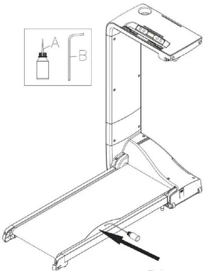
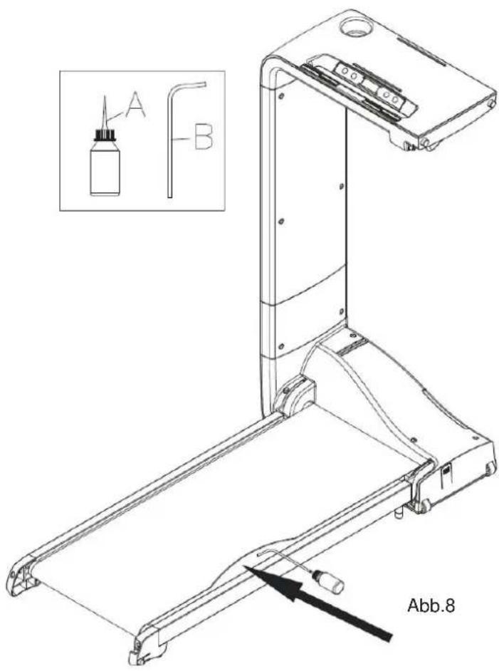
Fig.8
A. Lubricate your running deck if it's too dry or every 6 months to maintain optimal performance. NOTE: Lubricant is optional, please contact your supplier to gain more information.
B. Insert the spray nozzle (B) into the spray head of the lubricant can (A).
C. While lifting the side of the running belt, gently position the spray nozzle with little drop between the running belt and the running deck from the front of the treadmill to the rear.
NOTE: If you lubricate too much, the running belt may slip or liquid may from the machine.
D. Repeat the above procedure on the other side of the belt.
E. Then run the treadmill without anyone on it for at least 2\~3 minutes to let the lubricant spread evenly across the running deck and underside of the running belt.
F. Check the running belt whether is off-center or slips - if it does, go to page 20 to center the belt or adjust the belt tightness until the running belt has been tightened properly.
G. Plug in the power cord to start using the treadmill.
Running belt adjustment instructions
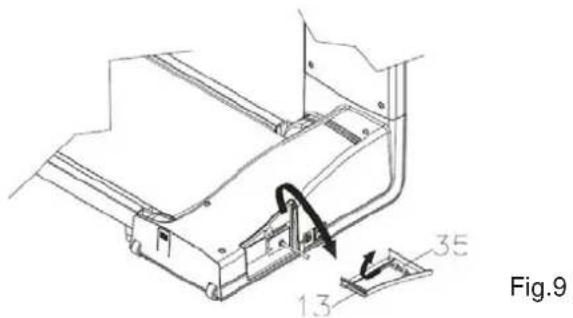
A. Open the Storage Door (13).
B. Allen Wrench (35) is attached on back of the Storage Door (13).
C. To adjust the belt, follow the steps on the next page.
ASSEMBLY INSTRUCTIONS
CENTERING THE BELT:
- If the belt is slightly off-center, first run the treadmill without anyone on it at 10 kph (6 mph) for at least 5\~10 minutes to see whether the treadmill could automatically center the running belt. If not, move to step 2 to start centering the belt.
- Stand behind the treadmill, with the treadmill running at 10 kph (6 mph) observe the running belt. If the belt tracks off center to the left or right, pay attention to the following process to center the belt.
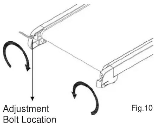
If the running belt is off center to the LEFT (fig.10):
Use the Allen Wrench
a. to turn the left rear roller adjustment bolt 1/4 turn in clockwise direction, which moves the running belt to the right.
b. or turn the right rear roller adjustment bolt 1/4 turn in counterclockwise direction, which moves the running belt to the right.
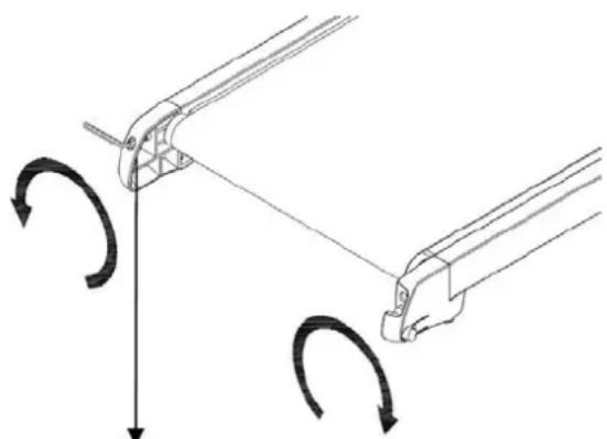
If the running belt is off center to the RIGHT (fig.11):
Use the Allen Wrench
a. to turn the right rear roller adjustment bolt 1/4 turn in clockwise direction, which moves the running belt to the left.
b. or turn the left rear roller adjustment bolt 1/4 turn in counterclockwise direction, which moves the running belt to the left.
Caution:
- Do not turn the adjustment bolts more than 1/4 turn at a time. Overtightening the belt can damage the treadmill.
- Be very careful to keep your fingers and any objects away from the belt and rollers.
natural_image
Diagram showing two mechanical linkage mechanisms with rotational arrows indicating motion (no text or symbols)Adjustment
Bolt Location
Fig.11
ASSEMBLY INSTRUCTIONS
Repeat the above procedure until the walking belt is centered. It may be necessary to test walking belt tension once you have completed the above procedure if the belt feels like it's slipping while walking. Refer to the below "Walking Belt Slipping" instructions.
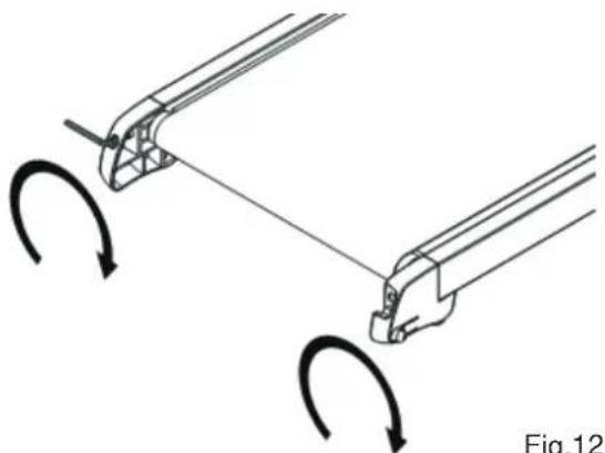
WALKING BELT SLIPPING: If the running belt slips when used
natural_image
Diagram showing two mechanical arms with curved arrows indicating rotation or motion (no text or symbols)Fig.12
-
First remove and unplug the power cord. Using the Allen Wrench, turn both left and right rear roller adjustment bolts clockwise, usually a 1/4 turn. NOTE: NEVER TURN the bolts more then 1/4 turn at a time and always keep the running belt centered.
-
Test the tightness of the belt. NOTE: Overtightening the belt can damage the treadmill.
-
Plug in the power cord, insert the key and walk on the treadmill at low speed (around 2 kph/1mph) to determine if the belt is still slipping. If the belt is still slipping, repeat the above procedure until the walking belt has been tightened properly.
The safety key
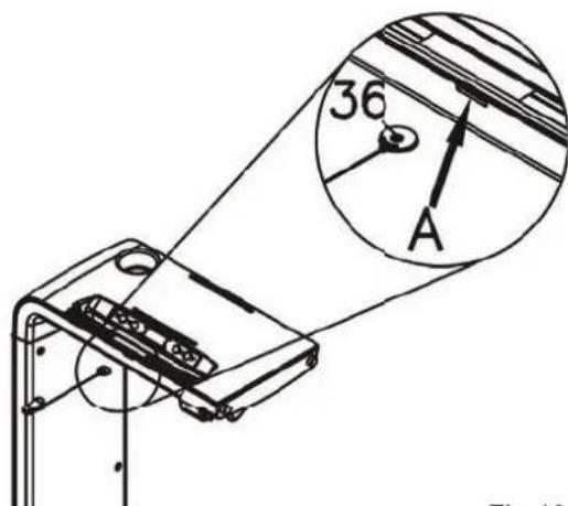
Fig.13
The safety key(36) immediately disconnects the power supply in case of an emergency, e.g. when you fall. In order to function properly, one end of the key should be inserted into the device (position A as per illustration on left side) and the other end (clip end) should be attached to your clothing (e.g. on the waistband).
In case of an emergeny, just pull on the rope, which will disconnect the key from the device and the device will stop immediately.
The running belt only starts moving, if the safety key has been inserted into the device properly.
Please keep the safety key securely after your workout and out of reach of children!
EXERCISE COMPUTER
Console operation
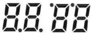
Take a few minutes to review the console layout. Below is an overview of the console's features and functions.
We recommend that you use the console to help vary your workout routine and keep you focused on your process toward your fitness goals. The console can become an important source of motivation and interest which will help keep you on track.

START / PAUSE

MODE
Time
Speed
Distance
Calories
Power On
a. Make sure to plug the power cord into an electrical outlet.
b. Turn on the Main Power Switch located at the front of the treadmill.
Power Off
The console would automatically go to SLEEP mode after 3 minutes of inactivity.
Console Buttons

START / PAUSE

natural_image
Abstract geometric symbol with two curved lines inside a diamond shape (no text or symbols)MODE

a. Press START/PAUSE to begin your exercise. b. Press START/PAUSE again to stop and pause all functions. c. Press START/PAUSE again to resume the program and all the date displayed will continue until the program has finished.
a. Press MODE to review each following function TIME – SPEED – DISTANCE – CALORIE – PULSE). b. Continue press MODE for 3 seconds until having a short beep sound. The computer will then automatically rotate display the following functions. Each function will display for 5 seconds on TIME – SPEED – DISTANCE – CALORIE – PULSE.
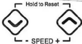
a. Press SPEED (+) to increase the setting values of SPEED. b. Press SPEED (-) to decrease the setting values of SPEED. c. HOLD TO RESET function: Continue pressing SPEED (+) and SPEED (-) together, all the date will return to 0 and the console will return to POWER ON status.
EXPLODED DRAWING
In case of mechanical problems use this explosion drawing. All parts are marked with a part number in it. Tell us this number in order to replace the respective part (within warranty time this service may be free of charge).
If necessary, you may additionally use the free user manual in pdf-format, available on www.skandika.com. You may enlarge the explosion drawing there with a factor up to 500 %.
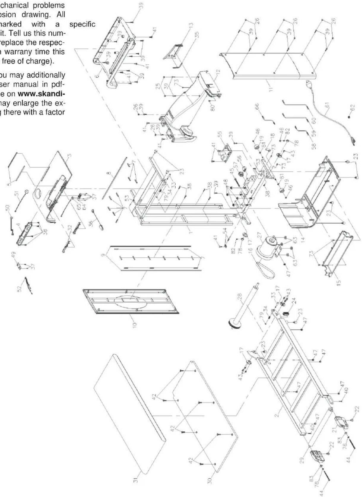
PART LIST
| No. | Item name Q'ty No. Item name Q'ty | ||||
| 1 | Main Frame 1 37 Screw (M2.6×8mm) 6 | ||||
| 2 | Running Deck Frame 1 38 Screw (M4×12mm) 9 | ||||
| 3 | Upper Console Table Cover 1 39 Screw, Pan Head | M4×2 | 0mm) 20 | ||
| 4 | Console 1 40 Screw, Flat Head (M4×20mm) 2 | ||||
| 5 | Non-Slip Strip | 2 41 Screw (M8×p1.25×25mm) 9 | |||
| 6 | Bottom Console Table Cover | 1 42 Bolt (M8×p1.25×25mm) 6 | |||
| 7 | Shock Absorption Strip (35mm) | 20 | 43 | Bolt (M6×p1.0×10mm) | 7 |
| 8 | Shock Absorption Strip (470mm) | 1 44 Bolt (M6×p1.0×80mm) 2 | |||
| 9 | Shock Absorption Strip (780mm) | 2 45 Bolt (M8×p1.25×55mm) 1 | |||
| 10 | Outer Upright Cover | 1 | 46 | Nylon Nut (M6×p1.0) | 3 |
| 11 | Inner Upright Cover | 1 | 47 | Nylon Nut (M8×p1.25) | 7 |
| 12 | Upper Motor Cover | 1 48 Thin Nylon (M10×p1.5) 4 | |||
| 13 | Storage Door | 1 49 Heart Rate Board 1 | |||
| 14 | Bottom Motor Cover | 1 50 Heart Rate Connection Wire 1 | |||
| 15 | Bottom Side Cover | 1 51 Speaker Wire 1 | |||
| 16 | Belt | 1 52 Hand Pulse Wire 1 | |||
| 17 | Roller Plug | 2 | 53 | Middle Connection Wire | 1 |
| 18 | Locking Button | 1 54 Sensor Wire 1 | |||
| 19 | Transportation Wheel | 2 55 Control Board 1 | |||
| 20 | Left Rear EndCap | 1 56 Breaker 1 | |||
| 21 | Right Rear EndCap | 1 57 Power Switch 1 | |||
| 22 | Stand | 2 | 58 | Connection Wire A | 1 |
| 23 | Leveler | 8 59 Connection Wire B 1 | |||
| 24 | Front Plug for Running Deck Frame | 1 60 Connection Wire B 1 | |||
| 25 | Shock-Absorbing Elastomer | 6 61 Power Cord 1 | |||
| 26 | Round Plug | 10 | 62 | Power Cord Stopper | 1 |
| 27 | Motor | 1 | 63 | Washer (10×23×2.0t) | 4 |
| 28 | Front Roller | 1 64 Safety Key Socket 1 | |||
| 29 | Rear Roller | 1 65 Miniature switch 1 | |||
| 30 | Running Deck | 1 66 Grounding Wire 1 | |||
| 31 | Running Belt | 1 73 Screw (M4×10mm) 5 | |||
| 32 | Hand Pulse Sensor | 4 | 76 | Washer (6×13×2.0t) | 2 |
| 33 | Locking Button Axle | 2 | 78 | Retaining Ring | 2 |
| 34 | Locking Button Spring | 2 79 E-Ring 2 | |||
| 35 | Allen Wrench | 1 | 80 | Screw (M3 x 6mm) | 1 |
| 36 | Safety key | 1 | 81 | Nylon washer (8 x 16 x 1.0t) | 2 |
| 82 Screw (M6×p1.0×10mm) | 2 | ||||
| 83 | Washer (6×20×2.0t) | 2 | |||
Exploded drawing see page 23
GUARANTEE CONDITIONS
For our devices we provide a warranty as defined below.
- In accordance with the following conditions (numbers 2-5) we repair defect or damage to the device free of charge, if the cause is a manufacturing defect. Therefore, these defects / damages need to be reported to us without delay after appearance and within the warranty period of 24 months after delivery to the end user. The warranty does not cover parts, which easily break (e.g. glass or plastic). The warranty does not cover slight deviations of the product, which are insignificant for usability and value of the device and damage caused by chemical or electrochemical effects and damages caused by penetration of water or generally force majeure damage.
- The warranty achievement is the replacement or repair of defective parts, depending on our decision. The cost of material and labor will be borne by us. Repairs at customer site cannot be demanded. The proof of purchase along with the date of purchase and / or delivery is required. Replaced parts become our property.
- The warranty is void if repairs or adjustments are made, which are not authorized by us or if our devices are equipped with additional parts or accessories that are not adapted to our devices. Furthermore, the warranty is void if the device is damaged or destroyed by force majeure or due to environmental influences and in case of improper handling / maintenance (e.g. due to non-observance of the instruction manual) or mechanical damages. The customer service may authorize you to replace or repair defective parts after telephone consultation. In this case, the warranty is not void.
- Warranty services do not extend the warranty period nor do they initiate a new warranty period.
- Further demands, especially claims for damages which occurred outside the device, are excluded as long as a liability is not obligatory legal.
- Our warranty terms - which cover the requirements and scope of our warranty conditions - do not affect the contractual warranty obligations of the seller.
- Parts of wear and tear are not included in the warranty.
- The warranty is void if not used properly or if used in gyms, rehabilitation centers and hotels. Even if most of our units are suitable for a professional use, this requires a separate agreement.
Environmental protection
At the end of its life cycle, this product must not be disposed of with household waste but must be taken to a collection unit for the recycling of electric and electronic equipment. The symbol on the product, the instructions for use or the packaging express mention of this. The basic materials can be recycled as specified on the labelling.
When recycling the materials and finding other utilisation for used equipment, you are making a significant contribution towards protecting our environment. Ask at your council about the respective local disposal sites.
For service, accessories and spare parts, please contact: info@skandika.com
Service centre: MAX Trader GmbH, Wilhelm-Beckmann-Straße 19, 45307 Essen, Germany
NOTIZEN | NOTES
NOTIZEN | NOTES
- WILLKOMMEN
- Bevor Sie beginnen
- AUFBAUANLEITUNG
- Schmieranweisungen
- Einschalten
- Congratulations on the purchase of your Skandika Home Run!
- Safety notes
- CAUTION: THE MAXIMUM LOAD SHOULD NOT EXCEED 120KG / 265LBS FOR THIS DEVICE.
- TABLE OF CONTENTS
- ASSEMBLY INSTRUCTIONS
- Unfolding instructions
- Folding instructions
- Power cord operation instructions
- Power cord storage instructions
- Level adjustment instructions
- Moving the treadmill instructions
- Changing to table/bench instructions
- Lubrication instructions
- Running belt adjustment instructions
- CENTERING THE BELT:
- If the running belt is off center to the LEFT (fig.10):
- If the running belt is off center to the RIGHT (fig.11):
- Caution:
- WALKING BELT SLIPPING: If the running belt slips when used
- The safety key
- EXERCISE COMPUTER
- Console operation
- Power On
- Power Off
- Console Buttons
- EXPLODED DRAWING
- PART LIST
- GUARANTEE CONDITIONS
- For our devices we provide a warranty as defined below.
- Environmental protection
- NOTIZEN | NOTES
Brand : Skandika
Model : Home Run
Category : Treadmills