PP96GGG50CH - Cooker Freggia - Free user manual and instructions
Find the device manual for free PP96GGG50CH Freggia in PDF.


| Product Type | Freestanding Gas Cooker with Gas Oven and Grill |
| Brand | Freggia |
| Model | PP96GGG50CH |
| Overall Dimensions (H x W x D) | 85 cm x 90 cm x 59 cm (closed); 100 cm depth with door open |
| Oven Volume | 119 L |
| Oven Type | Gas oven with in-built fan and thermostat (50-280°C) |
| Grill Type | Gas grill with spit function |
| Hob Burners | 5 gas burners: 1 auxiliary (1.00 kW), 1 semi-rapid (1.65 kW), 1 rapid (2.80 kW), 1 triple-flame (4.00 kW), 1 additional (semi-rapid or rapid) |
| Ignition | Automatic electric ignition on all burners |
| Safety Features | Flame failure device (thermocouple) on all burners, safety chains, child lock (not specified) |
| Control Type | Digital touch display with clock, timer, and semi-automatic cooking programs |
| Power Supply | 230 V ~ 50 Hz; for electric components (ignition, fan, light) |
| Energy Source | Natural gas (G20) or LPG (G30/G31) - convertible |
| Oven Cleaning | Catalytic self-cleaning on side and rear walls |
| Oven Door | Removable door for easy cleaning |
| Interior Light | Yes, 15 W E14 bulb, replaceable |
| Spit Function | Yes, with motor |
| Ventilation | Tangential cooling fan, requires room ventilation |
| Installation Requirements | Adjustable feet, gas connection (metal or rubber hose), safety chains, 230 V electrical outlet |
| Included Accessories | Knob guard for grill, drip tray, shelf, spit |
Frequently Asked Questions - PP96GGG50CH Freggia
User questions about PP96GGG50CH Freggia
0 question about this device. Answer the ones you know or ask your own.
Ask a new question about this device
Download the instructions for your Cooker in PDF format for free! Find your manual PP96GGG50CH - Freggia and take your electronic device back in hand. On this page are published all the documents necessary for the use of your device. PP96GGG50CH by Freggia.
USER MANUAL PP96GGG50CH Freggia
Thank you for purchasing Freggia cooker.
Please carefully read the user manual, as it contains the instructions for the safe installation, operation and maintenance of the cooker.
Save it for future use.
RU
Important safety information.
ВНИМАНИЕ!
Edditional recommendations regarding usage.
Care and maintenance.
COBET:
ACCENSIONE ELETTRICA....11
DISPOSITIVO DI SICUREZZA (CONTROLLO DI GAS)......11
COME SI USA LA CUCINA....11
Figura 5
Figura 6
natural_image
Line drawing of an open refrigerator with lid, showing internal compartments and ventilation slots (no text or symbols)Figura 7
natural_image
Line drawing of a cabinet with attached pipe and chain, set against a tiled wall (no text or symbols)Figura 9
natural_image
Technical line drawing of a mechanical device with a side view showing a handle and curved component (no text or symbols)Figura 10
natural_image
Technical line drawing of a mechanical assembly with a lever and mounting bracket (no text or symbols)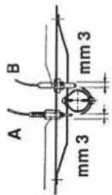
A = TERMOCOPPIA
B = CANDELLA
Figura 14
• RACCOMANDAZIONI IMPORTANTI
natural_image
Technical line drawing of two mechanical components labeled A and B, shown with no text or symbols.Figura 15
ACCENSIONE ELETTRICA
natural_image
Line drawing of an open refrigerator with shelves and doors (no text or symbols)Figura 17
natural_image
Pure technical line drawing of a mechanical clamp or bracket (no text or symbols)Figura 18
natural_image
Technical line drawing of a mechanical assembly inside a housing (no text or symbols)Figura 19
natural_image
Illustration of a kitchen sink with chopsticks and a cup, no text or symbols presentFigura 24
DIRETTIVA EUROPEA 2012/19/EEC (WEEE)
GENERAL INFORMATION....16
PP96GEE50 RANGE COOKERS....17
POWER SUPPLY INDICATOR (RED)....17
OVEN IGNITION INDICATOR (AMBER)....17
OVEN THERMOSTAT KNOB....17
OVEN PROGRAMME CONTROL KNOB....17
DIGITAL DISPLAY WITH TOUCH CONTROL....17
SETTING THE CLOCK....17
MANUAL MODE....18
TIMER....18
SEMI-AUTOMATIC SET-TIME COOKING....18
SEMI-AUTOMATIC SET STOP-TIME COOKING....18
MULTI-FUNCTIONAL ELECTRIC OVEN WITH
IN-BUILT FAN....18
ELECTRIC GRILL....18
PP96GGG50 RANGE COOKERS....19
DIGITAL DISPLAY WITH TOUCH CONTROL....19
SETTING THE CLOCK....19
TIMER....19
SWITCHING ON THE OVEN/THE THERMOSTAT/
SWITCHING ON THE GRILL....19
INTERNAL LIGHTING ON/OFF BUTTON....19
IN-BUILT FAN ON/OFF BUTTON....19
GAS OVEN....20
SWITCHING ON THE MAIN GAS OVEN BURNER......20
USING THE GAS OVEN....20
IGNITING THE GAS GRILL INJECTOR....20
USING THE GAS GRILL....20
INSTALLATION AND SWITCHING ON....21
CONNECTING TO THE MAINS....21
INSTALLATION....21
SAFETY CHAINS....21
ROOM VENTILATION....21
PLACEMENT....21
INSTALLATION OF THE FEET 21
CONNECTING TO THE GAS SUPPLY....21
CONNECTING WITH A METAL HOSE (A - Fig. 11)......21
CONNECTING WITH A RUBBER HOSE
(B and C - Fig. 11)....21
ADJUSTING FOR DIFFERENT TYPES OF GAS....22
REPLACING THE HOB BURNER INJECTORS (FIG 12)......22
REPLACING AN OVEN INJECTOR (FIG. 13)....22
REPLACING THE GRILL INJECTORS (FIG. 14)....22
REDUCED FLOW ADJUSTMENT FOR HOB
BURNERS (SETTING HOB BURNER MINIMUM LEVELS)......22
REDUCED FLOW ADJUSTMENT FOR OVEN BURNERS
(SETTING OVEN BURNER MINIMUM LEVELS)....22
CONNECTING TO THE MAINS....23
AUTOMATIC ELECTRIC IGNITION....23
GAS CONTROL SAFETY DEVICE....23
USING THE COOKER....23
GAS BURNERS....23
SWITCHING ON THE GAS HOB BURNERS....23
USING THE HOB GAS BURNERS....23
USING THE SPIT....23
GENERAL RECOMMENDATIONS REGARDING
OVEN USE....24
CARE AND MAINTENANCE....24
GENERAL RECOMMENDATIONS REGARDING SAFE TECHNIQUE....24
GENERAL RECOMMENDATIONS REGARDING COOKER CARE....24
CATALYTIC SELF-CLEANING OVEN....24
REMOVING THE OVEN DOOR....25
CLEANING THE COOKER'S GLASS AND CERAMIC SURFACE....25
CHANGING THE LIGHTING BULB (FIG. 21)......25
EUROPEAN DIRECTIVE 2012/19/EEC (WEEE)....25
EUROPEAN REGULATION N° 1935/2004 REGARDING THE MATERIALS WHICH ARE TO COME INTO CONTACT WITH FOOD PRODUCTS....25
APPENDIX 1. TECHNICAL CHARACTERISTICS......26
DIMENSIONS....26
GAS BURNER CHARACTERISTICS....26
ELECTRIC OVEN POWER....26
USEFUL INFORMATION REGARDING ELECTRIC OVEN ENERGY CONSUMPTION....26
WARNING!
- The appliance and its external parts get hot when it is in use. Be careful not to touch the heaters, Children under 8 should remain at a distance or be supervised by adults.
- Children under 8, as well as people with special needs, or those lacking in experience and knowledge, can use this appliance provided they are supervised or were given instructions as to how to use it safely and correctly, and that they are fully aware of the risks.
- Children should not be allowed to play with the appliance, or to clean and adjust it without adult supervision.
- Never leave a switched-on cooker cooking oils and fats unattended. It can be dangerous and cause a fire.
- Never use water to put out flames! First, disconnect the appliance from the mains, and only then extinguish flames, if possible by covering the source of the fi re with a fi re-resistant blanket or cover.
- The internal surfaces of the kitchenware drawer (if it has been included in your package) can get hot.
- Before taking off the protective cover, wipe off any liquid from its surface.
Important!
Before changing the lighting bulb inside the oven make sure that the appliance is disconnected from the mains – to avoid possible injury from electrical current.
- When in use, the appliance gets very hot. Be careful: don't touch the heaters inside the oven.
- Before connecting to the mains, you should prepare a device, which will be able to disconnect the appliance from the mains. A gap between the contacts in this device should be able to ensure total disconnection if the voltage increases to category III, according to the installation manual.
- The appliance must be disconnected from the mains during installation, maintenance, cleaning and repair procedures. It is dangerous to touch any appliance parts that are live.
- Don't use compartments intended for warming up plates and storing gas cylinders (if such compartments are part of your product) to store infl ammable liquids or materials, such as wood, paper, sprays, liquids and gas under pressure, matches etc.
- From time to time, check the condition of the supply cord connecting the cooker with the gas supply: make sure it does not contact the heating surfaces, that it is not trapped, signifi cantly bent or damaged. When damaged, the cord should be immediately replaced. It is also needs to be replaced by the set date. Both ends of the cord should be fixed with approved standard clamps, guaranteeing safety.
- If in time, a gas valve becomes difficult to open, we recommend calling a technical services expert.
- Clean the ceramic and chrome parts of the cooker in soapy water or non-abrasive cleaning products. To clean burner bodies and caps and saucepan carriers you can use a metal scourer. Thoroughly dry out clean surfaces.
- Don't use abrasive cleaning products to clean the ceramic and chrome parts of the appliance.
- During cleaning, try to avoid the burner plate of the cooker. Avoid getting water into injector openings.
- Always keep clean ignition candles and dry them out after every use of the cooker, particularly if some liquid was spilled from saucepans during cooking.
- If the cooker has got a glass cover, never close it before the burners and heated surfaces of the burner plate have cooled down. Otherwise, the cover can crack or get damaged.
- Protect the ceramic parts of the cooker and ignition candles from physical impact.
- Do not use the door handle to move the cooker around.
- It is not advisable to use rough abrasive products and sharp metallic scourers to clean glass doors – they can get scratched or the glass can get damaged.
- Do not use steaming devices for cleaning the device.
• This cooker does not need a special stand for installation. - This device is not intended to be switched on by an external timer or a separate remote control system.
-
If cracks appear on the cooker surface, disconnect it from the mains to avoid possible electrical shock.
-
When the gas cooker is in use, it creates extra heat, humidity and by-products of combustion in the room where it is installed. Make sure that the room is well-ventilated, particularly when the cooker is in use: do not close natural ventilation openings, and switch on (or install if you do not have one) a device for mechanical ventilation (an extractor).
- The product can only be used for cooking. Do not use it for any other purpose, like heating the premises.
The manufacturer does not accept any responsibility for any damage and faults of the product, as well as accidents, caused by not following the installation and usage recommendations.
If you discover a fault, or a gas leak, or damaged electrical cords, immediately report it to the Service Centre and arrange an expert visit.
GENERAL INFORMATION
Thank you for choosing and buying one of our high-quality products. We are hoping very much that in your hands our cookers will function most effectively, and provide the best results, living up to your expectations. With this in mind, we suggest that you read the manual carefully and follow its instructions. It is important to understand that the manufacturer does not accept responsibility for any damage or faults of the product, as well as accidents, caused by not following the installation and usage recommendations.
To produce cookers that live up to modern technological demands and/or to continuously enhance the quality of our products, the company reserves the right to introduce any changes without prior notice, which will not however cause any problems or difficulties for the user.
If you need to order spare parts or accessories for the product, get in touch with your seller or call the company helpline, stating the model number and the serial number, which you will find on the manufacturer's identification panel. This panel can be found either inside the compartment for warming-up plates (if your model does have this compartment) or on the external back wall.
The cooker complies with the following standards:
• CEE 2009/142/ (30/11/2009)
• 2006/95/EC Low Voltage directive (12/12/2006 and further amendments)
- CEE 2004/108 (on radio interference levels) – 15/12/2004)
• EUROPEAN REGULATION N° 1935/2004 (food contact materials)
• EUROPEAN REGULATION N° 1275/2008
• CEE 40/2002
• CEE 92/75
• 2012/19/EEC (WEEE)
• 2005/32/EC (equipment, using electricity)
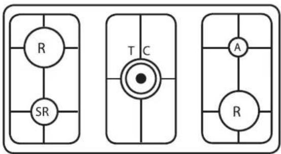
GAS BURNER PLATE
flowchart
graph TD
    A["R"] --> B["SR"]
    C["T"] --> D["C"]
    E["A"] --> F["R"]
    G["T"] --> H["C"]
    I["T"] --> J["C"]
    K["T"] --> L["C"]
    M["T"] --> N["C"]
    O["T"] --> P["C"]
Figure 1
SR – Normal gas burner;
R - Rapid gas burner;
A – Auxiliary gas burner;
TC – a gas burner with three rows of flames.
CONTROL PANEL
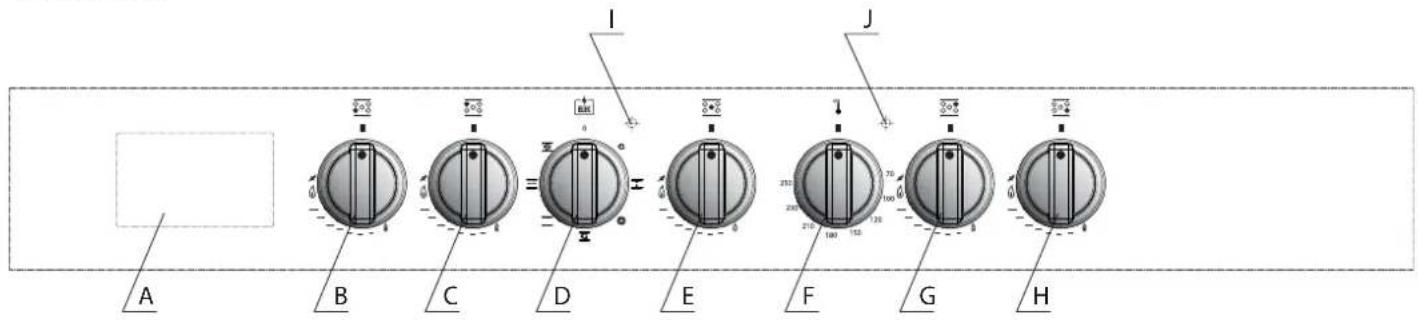
Figure 2
A – digital display with touch control;
B — left front burner knob – used to switch on and adjust the flame
C — left rear burner knob – used to switch on and adjust the flame;
D — oven setting control knob;
E — central burner knob – used to switch on and adjust the flame;
• POWER SUPPLY INDICATOR (RED)
If the indicator is lit, it means the oven is functioning properly and is switched on.
• OVEN IGNITION INDICATOR (AMBER)
When this indicator is switched on, it means that the oven is in the preliminary heating phase.
The oven thermostat controls the cooking temperature in all settings, including those for the grill. Turning the corresponding knob clockwise will allow you to set the temperature inside the oven at the required level within the range of 50irc C and 250irc C.
• OVEN PROGRAMME CONTROL KNOB
The knob will activate the required setting needed for cooking. The description of the settings, and tips how to choose them, can be found in the chapter "MULTIFUNCTIONAL ELECTRIC OVEN WITH IN-BUILT FAN".
F — oven thermostat handle;
G — right rear burner knob – used to switch on and adjust the flame;
H — right front burner knob – used to switch on and adjust the flame;
I — power supply indicator (red);
J — oven ignition indicator (amber).
DIGITAL DISPLAY WITH TOUCH CONTROL
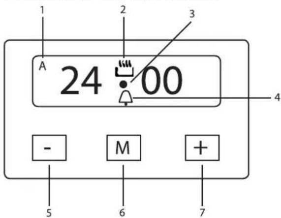
Figure 3
- An automatic programme is in use (in some models you will see an inscription "Auto" instead of the letter A).
- Manual control setting.
- This indicator flashes when the timer is being set up
- This indicator shows when a timer is activated.
- A button used to decrease the time when a timer is being set. It is also used to choose an audio signal level (three levels are available).
- Setting selection button.
- Button used to increase the time, when a timer is set.
- SETTING THE CLOCK
The first time you switch the appliance on, as well as after a power cut, the digits and the indicator A on the display will flicker, and the cooker will not operate in this position.
- After switching on the cooker, press the M button and hold for at least 2 seconds, until the symbol A disappears. A flashing • symbol will appear on the display.
- Using the - and + buttons, set the time.
- A few seconds after the last depression of the buttons, the chosen time will be automatically saved.
- MANUAL MODE
The oven will operate in a manual mode (without a set cooking stop-time or set cooking period) only when this symbol is seen on the display: 📄.
- TIMER
The timer produces an audio signal when the set time is up without switching off the cooker. The maximum interval that can be set on a timer is 23 hours and 59 minutes. When the set time runs out, the symbol will disappear from the display, and the signal will sound. The audio signal will automatically stop in 7 minutes, or you can stop it by pressing any button on the display.
To set up the timer, please do the following:
- Press the M button and hold for at least 2 seconds, until a flashing symbol appears on the display.
- Using the - and + buttons, set the required interval.
- A few seconds after the last depression of the buttons, the timer will save the required time and will start the count-down time. ♠.
• SEMI-AUTOMATIC SET-TIME COOKING
- Set the required oven setting and the cooking temperature.
- Press the M button and hold for at least 2 seconds, until a flashing symbol appears on the display.
- Release the M button and press it again. A flashing A symbol will appear on the display as well as the sign "dur", which will eventually be replaced by 0:00.
- Using the - and + buttons, set the required cooking time (the maximum allowed is 10 hours).
- A few seconds after the last depression of the buttons, the time will be saved and the count-down will start. The symbols A and 📄 will appear on the display. To show the current time on the display, press the M button several times.
When the set time is up, a signal will sound, and the oven will automatically switch-off. The audio signal will automatically switch off in 7 minutes, or you can stop it by pressing any button on the display.
• SEMI-AUTOMATIC SET STOP-TIME COOKING
- Set the required oven setting and the cooking temperature.
- Press the M button and hold for at least 2 seconds, until a flashing symbol appears on the display.
- Release the M button and press it again. A flashing A symbol will appear on the display as well as the sign "dur"
- Press the M button once more. You will see the inscription "end" on the display, which will eventually change to 0:00.
- Using the and + buttons, set the required stop time.
- A few moments after the last depression of the buttons, the set time will be saved and the count-down will start. The symbols A and ☐ will appear on the display. To show the current time on the display, press the M button several times.
When the set time expires, an audio signal will sound, and the oven will automatically switch off. The audio signal will automatically switch off in 7 minutes, or you can stop it, by using any button on the display.
MULTI-FUNCTIONAL ELECTRIC OVEN WITH IN-BUILT FAN
Through combining various heating areas and an internal fan, the oven supports the following settings:
| De-frosting/ drying | In this setting only the fan is on, without the heating areas being activated. This function can be used to de-frost and/or dry out food using the air fl ow alone, circulating at the ambient temperature. This allows you to de-frost food without changing its taste and appearance. | |
| Upper + lower element | This setting ensures the simultaneous function of the upper and lower heating elements and is designed for preparing dishes which need to be slow cooked with the continuous addition of fl uids. This is a universal setting, ideal for preparing any kind of fried dish, bread, cakes, and baking in general. | |
| Ventilated cooking | A professional cooking setting, we recommend it for dishes dispersed across several oven shelves. Using this setting, dishes can be prepared independently of each other, for their odours will not mix. The even circulation of hot air enables slow, even preparation. | |
| Upper + lower element + fan | Activating the upper and lower heating elements alongside the fan guarantees the uniform distribution of heat within the oven. This setting enables you to prepare different dishes on one or more levels. When roasting meat the optimisation of the spread of heat allows you to cook at lower temperatures. This helps keep the meat more tender and decreases the amount by which it gets burnt. | |
| Grill | This setting allows you to grill meat, fi sh, poultry and vegetables. The thermostat knob must be set to the maximum temperature setting. | |
| Grill and spit | This enables you to spit-roast meat or poultry under the grill. | |
| Grill and spit with forced convection fan | This advanced cooking technology enables you to spit-roast larger servings of food, making meat browned on the outside and well-done. |
| De-frosting/ drying | In this setting only the fan is on, without the heating areas being activated. This function can be used to de-frost and/or dry out food using the air fl ow alone, circulating at the ambient temperature. This allows you to de-frost food without changing its taste and appearance. | |
| Upper + lower element | This setting ensures the simultaneous function of the upper and lower heating elements and is designed for preparing dishes which need to be slow cooked with the continuous addition of fl uids. This is a universal setting, ideal for preparing any kind of fried dish, bread, cakes, and baking in general. | |
| Ventilated cooking | A professional cooking setting, we recommend it for dishes dispersed across several oven shelves. Using this setting, dishes can be prepared independently of each other, for their odours will not mix. The even circulation of hot air enables slow, even preparation. | |
| Upper + lower element + fan | Activating the upper and lower heating elements alongside the fan guarantees the uniform distribution of heat within the oven. This setting enables you to prepare different dishes on one or more levels. When roasting meat the optimisation of the spread of heat allows you to cook at lower temperatures. This helps keep the meat more tender and decreases the amount by which it gets burnt. | |
| Grill | This setting allows you to grill meat, fi sh, poultry and vegetables. The thermostat knob must be set to the maximum temperature setting. | |
| Grill and spit | This enables you to spit-roast meat or poultry under the grill. | |
| Grill and spit with forced convection fan | This advanced cooking technology enables you to spit-roast larger servings of food, making meat browned on the outside and well-done. |
When any setting (except off) is activated, the red indicator light and internal oven lighting will both turn on.

NOTE: the yellow indicator light turns on once the thermostat has been activated. Before placing items in the oven, first heat it up for at least 10 minutes.
ELECTRIC GRILL
Cookers which are equipped with an electric oven and electric grill allow you to grill items with the oven door closed, without using the knob guard.

NOTE! When grilling food with the oven door closed, you must not set the temperature any higher than 200irc C.
GAS BURNER PLATE
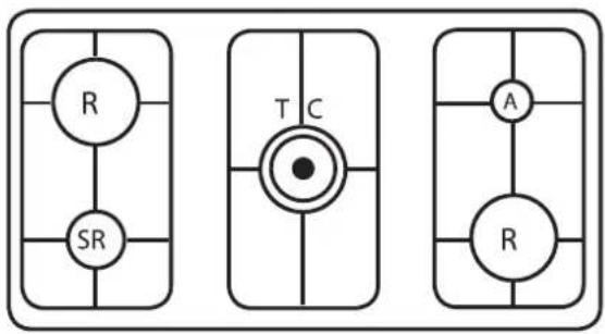
flowchart
graph TD
    A["R"] --> B["SR"]
    C["T"] --> D["C"]
    E["A"] --> F["R"]
    G["T"] --> H["C"]
    I["C"] --> J["T"]
    K["T"] --> L["C"]
    M["A"] --> N["C"]
    O["A"] --> P["C"]
SR - Normal gas burner;
R - Rapid gas burner;
A – Auxiliary gas burner;
TC – a gas burner with three rows of flames.
Figure 4
CONTROL PANEL
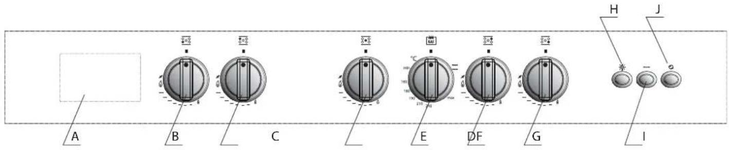
Figure 5
A – digital display with touch control;
B — left front burner knob – used to switch on and adjust the flame
C — left rear burner knob – used to switch on and adjust the flame;
D — central burner knob – used to switch on and adjust the flame;
E — switching on the oven knob/the thermostat knob/switching on the grill knob;
DIGITAL DISPLAY WITH TOUCH CONTROL
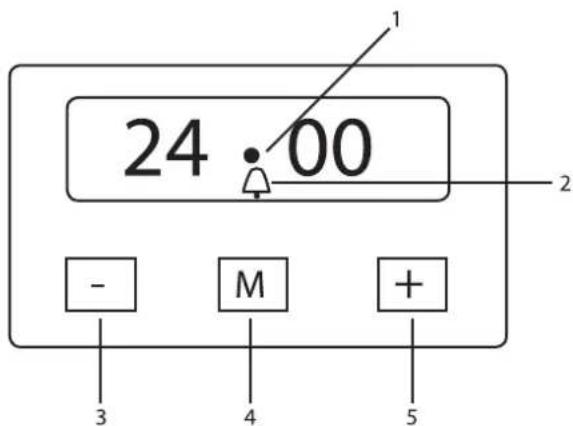
Figure 6
-
This indicator fl ashes when the time is being set up
-
This indicator shows when a timer is activated.
-
A button used to decrease the time when a timer is being set. It is also used to choose an audio signal level (three levels are available).
-
Setting selection button.
-
Button used to increase the time, when a timer is set.
- SETTING THE CLOCK
The first time you switch the appliance on, as well as after a power cut, the digits and the indicator A on the display will flicker, and the cooker will not operate in this position.
- After switching on the cooker, press the M button and hold for at least 2 seconds, until the symbol A disappears. A flashing • symbol will appear on the display.
F — right rear burner knob – used to switch on and adjust the flame;
G — right front burner knob – used to switch on and adjust the flame;
H — internal lighting on/off button;
I — turnspit switch on knob;
J — in-built fan on/off button.
-
Using the - and + buttons, set the time.
-
A few seconds after the last depression of the buttons, the chosen time will be automatically saved.
• TIMER
The timer produces an audio signal when the set time is up without switching off the cooker. The maximum interval that can be set on a timer is 23 hours and 59 minutes. When the set time runs out, the symbol will disappear from the display, and the signal will sound. The audio signal will automatically stop in 7 minutes, or you can stop it by pressing any button on the display.
To set up the timer, please do the following:
-
Press the M button and hold for at least 2 seconds, until a flashing symbol appears on the display.
-
Using the - and + buttons, set the required interval.
-
A few seconds after the last depression of the buttons, the timer will save the required time and will start the count-down time.
• SWITCHING ON THE OVEN/THE THERMOSTAT/SWITCHING ON THE GRILL
A thermostat knob allows you to switch on the main gas injector in the oven and to set the desired temperature for cooking.

ATTENTION!
PP96GGG50 range cookers are supplied with a gas oven with an in-built fan and gas grill, Detailed information on switching on the gas grill and on its functioning can be found in the "GAS OVEN" chapter.
• INTERNAL LIGHTING ON/OFF BUTTON
Used to switch on the internal lighting.
• IN-BUILT FAN ON/OFF BUTTON
By pressing this button, you activate the functioning of the in-built fan. It can be switched on alongside the main gas injector (GAS WITH VENTILATION mode), as well as independently (DE-FROSTING/DRYING mode). The simultaneous functioning of the fan and the grill is not allowed.
GAS OVEN
• SWITCHING ON THE MAIN GAS OVEN BURNER
- Open the oven door.
- Press the knob down and turn it anti-clockwise to the maximum flame position.
- To ignite the burner automatically, press the button down all the way.
- Without releasing a knob, make sure that the burner has lit up: watch the flame through special openings in the oven base.
• After 10 seconds or so, release the knob and check that the burner has not gone out. If it has, repeat the whole process again from the start.
- After switching a burner on, close the oven door and wait for 10 minutes while the oven heats up.
- Place the food to be prepared on an ordinary pan or any other container without handles, and put it on a chrome-plated shelf.
- Put the shelf with the pan into oven, and turn the knob pointer to the required setting.
- You can watch the cooking through a glass oven door when the internal lighting is on; open the door only when necessary (for example, if you need to add oil to the dish which is being prepared).

NOTE for cookers without a thermostat:
- when the knob pointer is set to the maximum temperature setting, it is at 280°C;
- when the knob pointer is set to the minimum temperature setting, it is at 150°C;
- all other temperatures between 150°C and 280°C are achieved approximately, moving the knob between the maximum and minimum heating positions.
Never place the thermostat in an intermediate position between the maximum heating ⚙ and the oven switched off ■ signs.
• IGNITING THE GAS GRILL INJECTOR
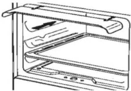
• Fit the knob guard to protect it from hot air, as shown in Fig 7.
natural_image
Line drawing of an open refrigerator with shelves and doors (no text or symbols)Figure 7
- Press the oven knob down and turn it to the right until it stops.
- Then bring a lit match to the perforated burner pipe and press the knob down all the way.
- Without releasing the knob, check that the burner has ignited.
- In 10 minutes or so, release the knob and make sure that the burner has not gone out.
- ATTENTION!
- When using ovens' and grill burners' electric ignition, you must keep the oven door completely open.
- When switching on the burners of ovens and grills equipped with electric ignition systems, do not press the ignition button down for more than 10 seconds. If the burner has not ignited during this time, release the button, open the oven door and wait at least one minute before repeating the switching on process. If the burner is not igniting because of a faulty electric ignition system, switch it on manually with a match, and then call technical services.
- WARNING
• Usually after a prolonged period out of use, it is difficult to switch on a burner immediately. Before ignition, wait a few seconds for air that has accumulated in the piping to escape.
- Watch that not too much gas be released together with air coming out of the burners. If a burner has not lit within several seconds, repeat the ignition by turning the control knob to the "off" ■ position, and then opening it again.
- When an oven or a grill is being used for the first time, smoke may come out, as well as an unpleasant smell caused by the heating of ceramic surfaces of oven walls and oil residue.
• USING THE GAS GRILL
- Fit the knob guard to protect it from hot air, as shown in Figure 7.
• Light the burner and wait for a few minutes while the oven is warming up. - Place the food to be prepared onto a shelf.
- Place the shelf in the oven along the highest runner.
• Under the shelf, place a drip tray. - Close the oven door, resting it against the knob guard.
- In a few minutes turn the grilled food upside down, to expose the other side to the infrared rays. This way both sides will be grilled equally. The time of cooking depends on the type of food and desired taste.
| Grilled food | Time, minutes | |
| Side 1 Side 2 | ||
| Thin cuts of meat | 6 | 4 |
| Fairly thick cuts of meat | 8 | 5 |
| Small fi sh without scales | 10 | 8 |
| Fairly big fi sh | 15 | 12 |
| sausages | 12 | 10 |
| Toast | 5 | 2 |
| Small poultry | 20 | 15 |

NOTE:
When the grill is turned on for the first time, you might notice some smoke coming out of the oven. Before starting cooking, it is advisable to wait until any oil residue burns off completely. While cooking under the grill you must set the maximum allowed temperature.
When in use, the appliance heats up a lot, so you must be careful and never touch any of the heated parts inside the oven. Besides, when the grill is in use, the external parts of the oven can heat up greatly. Do not allow children to come close to the oven!
CONNECTING TO THE MAINS INSTALLATION OF THE FEET
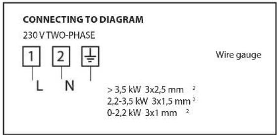
Figure 8
The voltage is shown on the manufacturer's identification plate. This plate can be found either inside a compartment for warming up plates (if such a compartment has been included with your package) or on the exterior rear wall of the cooker. One copy is stuck to this manual cover (only for gas or combi-cookers).
INSTALLATION
The appliance must be installed by a qualified person in accordance with the regulations in force. Prior to commencing installation, it is essential to ensure that the properties (nature and gas pressure) of the local gas supply network are compatible with the cooker. The conditions to be met are indicated on a sticker stuck to the cover of this manual. This cooker is not connected to any devices that extract combustion by-products. Such a device must be installed and connected to the cooker in accordance with existing guidelines on installation and usage. Cookers may only be installed in constantly ventilated buildings, in accordance with existing national regulations.
SAFETY CHAINS
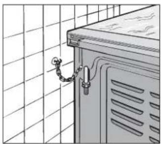
To avoid the accidental overturning of the cooker (for example, in case of a child climbing on the oven door), safety chains supplied with the cooker must be installed! They have to be fitted with a screw (not included in the package) to the rear wall, behind the appliance.
natural_image
Line drawing of a cabinet with attached pipe and chain, no text or symbols presentFigure 9
Make sure that the chains are fixed to the back of the cooker, tight and parallel to the floor. When the installation is complete, the safety chains must be fastened tight!
ROOM VENTILATION
The room intended for the installation of the gas cooker must have a constant supply of fresh air – this will ensure that the gas burns, and provide good ventilation. In particular, the amount of fresh air needed for combustion is at least 2 m3/h per kW of rated power.
When the gas cooker is in use, heat and moisture are emitted into the room where the cooker is installed. Ventilation of the room is essential, ventilation openings must be kept unobstructed or a permanent vent (extractor) must be installed. In case of long and intensive usage of the cooker, additional ventilation is needed – in this case you can open a window, for example, or increase the power of the in-built fan or an extractor.
PLACEMENT
Remove all packaging, including protective cling fi Im, from the chrome and stainless steel parts. Choose for installation a well-ventilated dry room without a draft. The cooker should not touch any materials which may be affected by heat, such as wood, lino, paper etc. – ensure a safe distance from them during installation. The cooker may be installed as a stand-alone or between two kitchen units, provided that these units' walls can withstand temperatures of up to 100°C, and that its height does not exceed the height of the burner plate.
Cookers have adjustable feet that are screwed bottom from four sides. With the help of the feet, you can adjust the height of the cookers to align its level due to nearby kitchen units and evenly distribute the liquid in the pot when cooking.

natural_image
Technical line drawing of a mechanical device with a base and wheels, showing internal components (no text or symbols)Figure 10
CONNECTING TO THE GAS SUPPLY
Before connecting the cooker to the gas supply, make sure that it is compatible with the type of gas to be used. Otherwise, act according to the chapter "Adjusting for different types of gas". A gas pipe should be connected on the right. If the pipe has to pass behind the cooker, it must be located at the lower part of the cooker (this area reaches temperatures of up to 50°C).
- CONNECTING WITH A METAL HOSE (A - FIG. 11)
Connect to a hose that complies with current national standards. The hose should be screwed onto the connector with a ring seal that had been added beforehand.
- CONNECTING WITH A RUBBER HOSE (B AND C - FIG. 11)
Connect to a rubber hose of a make which complies with current national standards. Both ends of the hose should be secured with standard hose clamps. It is essential to arrange for the hose to be replaced at the allotted time. In order to enable the hose to be maintained in good condition, you should have physical access to the hose along the whole of its length.
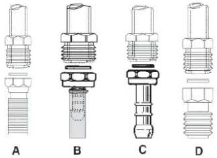
Figure 11
After connecting the cooker to the power supply, you must check that all connections are air-tight.
When working with butane/propane, check that the gas pressure is as indicated on the name plate.
ATTENTION! • Use only st
- Use only standard metal or rubber hoses.
- The pressure regulator must comply with national norms and standards.
- Hose joints should comply with the ISO 228-1 standards.
- Avoid sharp bending of pipes and hoses, don't over squeeze them and keep them well away from heated cooker walls.
ADJUSTING FOR DIFFERENT TYPES OF GAS
If the cooker is not already pre-set to operate with the type of gas available, it must be converted by following these steps:
- Replace the injectors (see APPENDIX 1);
• Regulate the primary air flow; - Regulate the minimum flow settings for all burners.

Note: after every such adaptation, you must stick to the nameplate the name of the new gas type to which the cooker has been set.
REPLACING THE HOB BURNER INJECTORS (FIG 12)
- Remove, the shelf, the burner caps (A) and the burners (B).
- Unscrew and remove the injector, which is found at the bottom of every injector holder (C).
- Replace injectors as shown in the table in Attachment 1, and screw and tighten them all the way.
- Check that injectors are air-tight.
- Put the burners, the burner caps and the shelf back into place.
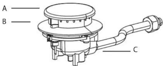
Figure 12
• IMPOTRTANT RECOMMENDATIONS
• Under no circumstances should you over-tighten the injectors.
• After replacing all the injectors, check that they are air-tight.
REPLACING AN OVEN INJECTOR (FIG. 13)
- Loosen the screw securing the cooker base.
- Remove the cooker base (by pushing it back and lifting).
- Remove the oven injector, after first loosening the screw fastening it in place.
- Replace the injector, using a 7 mm socket wrench.
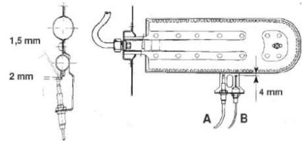
A = THERMOCOUPLE
B = SPARK PLUG
Figure 13
REPLACING THE GRILL INJECTORS (FIG. 14)
- Remove the injector, by loosening the two screws fastening it in place.
- Replace the injector, using a 7 mm socket wrench.
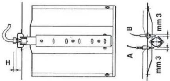
A = THERMOCOUPLE
B = SPARK PLUG
Figure 14
• IMPORTANT RECOMMENDATIONS
• Under no circumstances should you over-tighten the injectors.
• After replacing all the injectors check that they are air-tight.
REDUCED FLOW ADJUSTMENT FOR HOB BURNERS (SETTING HOB BURNER MINIMUM LEVELS)
If the cooker is intended to work on bottled gas (butane/propane), the thermostat bypass must be screwed right down. A cooker can be equipped with type A taps with a by-pass inside (accessed by inserting a small screwdriver into the rod) or type B taps, with a by-pass on the right (accessed directly); see figure 15.
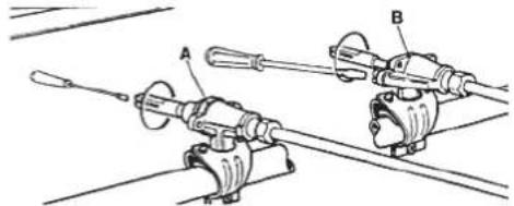
natural_image
Technical line drawing of two mechanical components labeled A and B, connected by rods (no text or symbols present)Рисунок 15
If the cooker is intended to work on natural gas, proceed as follows, no matter what type of tap is used:
- Ignite the burner and turn the knob to the maximum flame position.
- Remove the knob by pulling it towards you, without putting pressure on the front panel of the cooker to avoid damage.
• Using a small screwdriver, loosen the regulating screw, turning it by approximately 3 notches, moving anti-clockwise. - Turn the tap rod anti-clockwise again until it stops. In this position the flame will be at its maximum level.
- Very slowly screw the by-pass back in, without pushing the screwdriver, until the flame reduces to three-quarters of its maximum size. Make sure that the flame is sufficiently stable, even with moderate draughts.
REDUCED FLOW ADJUSTMENT FOR OVEN BURNERS (SETTING OVEN BURNER MINIMUM LEVELS)
If the cooker is intended to run on bottled gas (butane/propane), the thermostat by-pass must be screwed right down. If the cooker is intended to run on natural gas, proceed as follows to adjust the minimal flame, no matter what type of tap is used:
- Remove the oven base (by pushing it to the back wall and lifting).
- Ignite the oven burner, turning the knob pointer to the maximum setting.
- Close the oven door.
- Access the thermostat or tap by-pass (see fig. 16).
- Loosen the adjustment screw by approximately three notches.
- In 5–6 minutes, turn the knob pointer to the maximum setting.
INSTALLATION AND SWITCHING ON
- Slowly retighten the by-pass, watching the fl ame decrease through the window in the closed oven door, until the size of the fl ame is reduced to approximately 4 mm. It is not recommended to keep the fl ame too low. It must be stable even when the oven door is opened or closed quickly.
- Switch off the burner and replace the oven base.
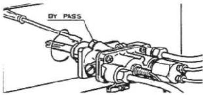
Figure 16
CONNECTING TO THE MAINS
Before connecting to the mains, make sure that:
- the mains voltage is as indicated on the nameplate;
• the earth connection is in good working order.
If the cooker is equipped with a power lead without a plug, a standard plug can be used to connect it. While connecting, please take into account the following:
- the green-yellow wire must be used to earth;
• the blue wire is for the neutral; - the brown wire is live;
- the lead must never touch the cooker walls, which heat up to over 75irc C ;
- if you need to replace a lead. use types HO5RR-F or HO5V2V2-F of a suitable size (see the CONNECTING TO THE ELECTRICAL MAINS DIAGRAM);
- if the appliance is supplied without a lead, for connecting use leads of HO5RR-F or HO5V2V2-F types of suitable size.
All cookers with ceramic glass burner plates or with four electric heating areas are supplied without a power cable.

ATTENTION!
The manufacturer does not accept liability for any damage caused during cooker connection by breaching the described above rules as well as the current safety regulations. Always ensure that the cooker's earth wire is earthed properly (see the CONNECTING TO THE ELECTRICAL MAINS DIAGRAM).
AUTOMATIC ELECTRIC IGNITION
All cookers are equipped with an automatic electric ignition system. The correct distances between an electrode and a burner are shown in figures 17 and 18.
If no spark is generated, do not persist, as it can damage the generator.
Possible causes of ignition system malfunctions are as follows:
• the spark plug is damp, dirty or broken;
- the gap between the electrodes and the burners is not correct;
• the spark plug wire is broken or missing its sheathing;
- the spark discharges to earth (in other parts of the cooker);
- a generator or a micro switch is damaged;
• built-up air in the pipes (particularly after a long period when the cooker was not in use);
- an incorrect gas-air mixture (poor fuel setting).
GAS CONTROL SAFETY DEVICE
The advantage of burners equipped with such a device is that in case of the spontaneous extinguishing of a flame, a defence system comes into force: gas supply to the extinguished burner stops and it prevents the danger of a gas leak. After the spontaneous extinguishing of a flame, the safety device switches on automatically in under 90 seconds for hob burners, and under one minute for oven and grill burners.
The correct gap between the thermocouple sensor and the burner is shown in figures 13 and 14.
To check that the gas control safety valve is working properly, proceed as follows:
- ignite the burner and leave it working for approximately three minutes;
-
switch off the burner and turn the knob to the "off" position, indicated by the ■ symbol;
-
in 90 seconds for hob burners, and in one minute for oven and grill burners, turn the knob to the "on" position;
- leave the knob in this position and place a burning match to the burner. The burner should not ignite!
The time needed to excite the magnet during ignition is approximately 10 seconds.
The gas control valve switches on automatically after the flame is extinguished in under 90 seconds for hob burners, and under one minute for oven and grill burners.
- WARNING
- Before undertaking any cleaning or maintenance procedure, switch off the cooker and turn off the gas supply tap.
- When connecting a cooker to the gas supply, never check the gas circuit for leaks with a flame. If you do not have specialist equipment to control air-tightness, you can use foam or concentrated soapy water.
USING THE COOKER
GAS BURNERS
• SWITCHING ON THE GAS HOB BURNERS
- Press the regulating knob down and turn it anti-clockwise until it reaches the notch opposite the sign, on the front panel of the cooker (the maximum flame position).
• To ignite a burner automatically, press the button down all the way and hold it in this position for approximately 10 seconds. - Release the knob and make sure that the burner has started to burn. Otherwise, repeat from the start.
• USING THE HOB GAS BURNERS
Use saucepans of a diameter suitable for the burner type. The flame must not project beyond the base of the pan.
Recommendations:
- for the auxiliary burner use pans of at least 8 cm in diameter, using the adjusting grid supplied with the cooker;
• for normal burners, use pans 14 cm in diameter; - for a rapid or a triple-flame burner, use a pan no less than 22 cm in diameter.
A triple burner (a burner with three rows of flames) can be used for cooking in woks.

NOTE: Never leave a knob at settings between the maximum flame sign and the "shut" position.
WARNING!
- Never leave a hotplate switched on without any pans on it. If you are using the hotplate for the first time, it is recommended to leave it on for 10 minutes or so, so as to dry out any moisture and oil residues on its surface.
- Если зона нагрева не используется в течение длительного времени, рекомендуется слегка смазать ее поверхность жировой смазкой.
- When cleaning the heating surface, use abrasive materials.
USING THE SPIT
• SPIT-ROAST COOKING UNDER THE GRILL WITH OPEN DOOR
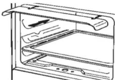
- Fit the knob guard to protect it from hot air as shown on figure 17.
natural_image
Line drawing of an open refrigerator with shelves and doorways (no text or symbols)Figure 17
USING THE COOKER
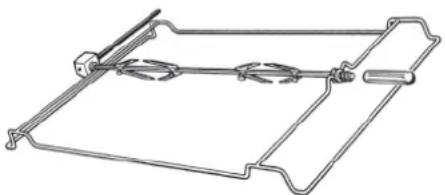
- Put a piece of meat on a spit, securing it in the center with special forks.
- Insert a spit into the tip located in the hub of the support frame.
- Remove the protective handle from the spit.
natural_image
Pure technical line drawing of a mechanical clamp or bracket (no text or symbols)Figure 18
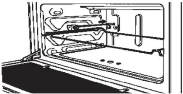
- Install a support frame of the spit in center of the oven and at the same time inserting the shaft into the hub counter of the micromotor.
natural_image
Technical line drawing of a mechanical assembly inside a frame (no text or symbols)Figure 19
- Place the drip tray in the bottom of the oven and do not forget to fill in some water.
- Switch on the burner of the grill.
- Gently close the oven door, resting it up against the knob guard.
- Switch on the spit, pressing the button on the front panel.
- After the procedure, remove the support frame from the hub of the micromotor and tighten a special pen on the spit.

NOTE:
watering the meat with fat from time to time during cooking.
• SPIT-ROAST COOKING WITH CLOSED DOOR
Cooking on a spit with closed door is similar to cooking with the open door, except the needs to use knob guard. The door is completely closed.
WARNING! Cooking using the grill is permitted only for ovens, equipped with an electric grill. The maximum cooking temperature should not exceed 200irc C.
WARNING!
Spit forks can have a sharp ends - be careful!
GENERAL RECOMMENDATIONS REGARDING OVEN USE
- Oven shelf: place drip trays on it for baking, stewing etc. (not included); meat can be prepared ("grilled") on the shelf itself.
- Drip tray: this is usually placed underneath the shelf and serves to collect any fluids that run off the food being prepared on the shelf, although it can be used for preparing dishes directly, too.
- If you are cooking in an oven with a ventilation system, then two shelves may be installed simultaneously. When doing so, it is important to bear in mind that, if the different food items you are looking to prepare differ from one another in quantity or quality, then they are also likely to have different preparation times.
- System for securing the shelves: the oven is fitted with a system for securing the shelves which allows them to be pulled out of the oven without removing them completely; although if it is necessary to completely remove the shelves, you can just lift them up and pull, as indicated in fig. 20.
CARE AND MAINTENANCE
GENERAL RECOMMENDATIONS REGARDING SAFE TECHNIQUE
Upon the discovery of faults, we recommend you do the following.
Before calling the technical support team, you must ensure that:
- the plug has been inserted into the socket properly;
• the oven on/off indicator is lit.
If this has not fixed the problem, call a qualified and authorized specialist who will be able to fix the fault.
If the oven lighting fails to come on, it is essential that you:
- unplug the cooker;
- remove the protective glass located at the back panel inside the oven;
- change the bulb.
GENERAL RECOMMENDATIONS REGARDING COOKER CARE
Disconnect the power supply before undertaking any kind of maintenance.
Do not steam-clean the appliance.
Do not use rough, abrasive or sharp metal scourers to clean the oven doors, since these may scratch or damage the door's surface and its glass panel.
Do not use acidic cleaning products (such as those used to remove limescale), since these may damage any enamelled oven parts.
Turn off the heating elements and wait for the inside of the oven to cool down before touching or cleaning them.
Be very careful around the grill heating elements; these can be very hot.
Clean the oven carefully, so as to avoid getting scalded by steam whilst wiping down hot oven parts with a wet cloth or sponge.
Furthermore, some cleaning agents emit toxic fumes when they come into contact with hot surfaces.
CATALYTIC SELF-CLEANING OVEN
The two side walls and the back of the oven are coated with a catalytic self-cleaning enamel.
Every 10-15 times it is used, leave the oven empty at full heat. The time required for cleaning depends on the condition of the oven.
Some splashes tend to set hard and may clog the pores of the special coating, preventing oxidation and eliminating its self-cleaning properties. In this case, as soon as the oven has completely cooled apply very hot water to soften the deposits and use a soft brush, without detergent, to remove them. Then switch the oven back on at maximum heat for a few minutes.

Important: never use metal brushes or abrasive substances for cleaning catalytic panels.
REMOVING THE OVEN DOOR
The oven door may be removed in order to make the process of cleaning the oven more convenient. Carry out the following instructions:
- Open the door fully.
- Turn the two levers marked "B", turning them from position 1 to position 2 (fi g. 20).
- Slowly start to close the door until it stops. Grip the door from both sides with both hands, close it further still and then remove it, lifting it upwards.
In order to fit the door in place again it is essential to carry out the door removal instructions in reverse order:
- Insert the two loops into their respective sockets and open the door fully.
- Turn the two levers marked "B", moving them back to position 1.
- Close the door in the usual manner.

Figure 20
CLEANING THE COOKER'S GLASS AND CERAMIC SURFACE
The flatness of the cooker's worktop makes care of the cooker significantly easier compared with cleaning the worktops of traditional cookers. Light stains may be removed with damp paper. In order to remove more stubborn stains you may use cleaning products and methods designed for cleaning glass.
If the contents of a saucepan have overfl owed onto the cooker surface, you may remove them with the help of a spatula. If it is sugar of syrup that has overfl owed, then these must be removed immediately, before they have had a chance to harden. The same goes for any bits of aluminium foil or plastic, if any items made of those materials accidentally end up on a still-hot cooking surface. Water-based stains and traces of limescale may be removed with white vinegar.
After using the glass and ceramic surface, always wash it down and dry it with water-absorbent paper. Under no circumstances should you use abrasive or corrosive cleaning products such as oven spray, grease-removal products, rust-removal products, polishing powders and abrasive sponges. Do not let sand get onto the cooker surface (when cleaning vegetables, for example) – for it may scratch the surface. If using a saucepan with a rough bottom, do not slide it back and forth along the cooker surface but lift it up, or else the pan may leave stains on the glass surface, or even scratch it.
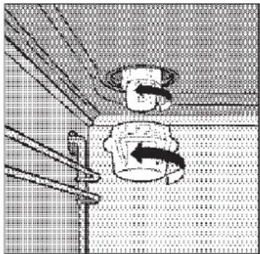
CHANGING THE LIGHTING BULB (FIG. 21)
So as to avoid electrocution and/or causing damage to people, read and follow the instructions indicated below.
- Unplug the cooker from the mains.
- Make sure that the oven and the light bulb have cooled, and then take off the protective covering. Do not touch a hot bulb with damp cloth, because this may cause the bulb to crack.
- Replace the bulb with another suitable 15 W, 230 V E14-type bulb, designed to be used at high temperatures.
In case the protective covering is damaged or broken, do not resume use of the oven until you have replaced it.
natural_image
Illustration of a kitchen sink with chopsticks and a bowl, no text or symbols presentFigure 24
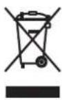
EUROPEAN DIRECTIVE 2012/19/EEC (WEEE)
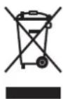
The following is only designed for owners of appliances whose technical details tags (passport tables) contain this symbol.
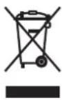
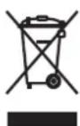
This symbol means that the product has been classified according to current regulations regarding electrical or electronic goods, and that it meets the requirements of Directive 2012/19/EEC (WEEE). Per the above, once it reaches the end of its life, it must be recycled separately from normal household waste. To do this, it is essential to take it down (for free) to an electrical or electronic goods recycling centre, or else to hand it back to its distributor, at the point of purchase of a new appliance.
The user carries the responsibility of taking the appliance to a recycling centre once it has reached the end of its life-cycle, or else face sanctions, as stipulated in the legislation regarding the recycling of waste.
Diff erentiated waste collection (for its future recycling, processing or use) that is performed in a manner compatible with the surrounding environment enables us to avoid making a negative impact on nature and on people's health, as well as enabling the materials that appliances are made of to be used several times over.
In order to get more detailed information on existing systems of waste collection you ought to ask your local recycling service, or else the shop where you bought the appliance.
Manufacturers and importers are responsible for ensuring that recycling, processing and utilisation are carried out in a manner safe for the environment, both when they are running an project on their own, and when they are doing so in concert with another party.
EUROPEAN REGULATION No 1935/2004 REGARDING THE MATERIALS WHICH ARE TO COME INTO CONTACT WITH FOOD PRODUCTS

This symbol, which may also be seen on packaging, indicates that the materials which these wares are made from, and which may potentially come into contact with food products, adhere to the requirements of European Regulation N° 1935/2004. Inside the body of the oven, food products may come into contact with oven shelves, drip trays, baking trays, the glass panel on the door of the oven, the rubber seals, the turnspit, and the oven walls.
With the hob, food may touch the pan stands, burners and the hob surface. In the food-warmer, contact may occur with the sides of the compartment.
APPENDIX 1. TECHNICAL CHARACTERISTICS
| DIMENSIONS | |
| Nominal external dimensions | |
| Height up to the work surface, cm 85 | |
| Depth with the oven door closed, cm 59 | |
| Depth with the oven door open, cm 100 | |
| Width, cm 90 | |
| Useful dimensions | |
| Width, cm 75 | |
| Depth, cm 48 | |
| Height, cm 33 | |
| Volume, l 119 | |
| GAS BURNER CHARACTERISTICS | |||||
| Gas type | Nominal pressure, mb | Burner type Nozzle | Reduced power, kW | Nominal power, kW | |
| G20 20 | Auxiliary 77 0,40 1,00 | ||||
| Semi-rapid 97 0,58 1,65 | |||||
| Rapid 123 | 0,80 2,80 | ||||
| Three rows of flames | 145 | 1,70 4,00 | |||
| Oven | 140 | 1,20 3,70 | |||
| Grill | 120 - | 2,50 | |||
| G30 | 28-30 | Auxiliary 50 0,40 1,00 | |||
| Semi-rapid 65 0,58 1,65 | |||||
| Rapid | 83 0,80 | 2,8 | |||
| Three rows of flames | 98 1,70 | 4,00 | |||
| Oven | 95 1,20 | 3,70 | |||
| Grill | 80 | - | 2,50 | ||
| G31 37 | Auxiliary 50 0,40 1,00 | ||||
| Semi-rapid 65 0,58 1,65 | |||||
| Rapid | 83 0,80 | 2,8 | |||
| Three rows of flames | 98 1,70 | 4,00 | |||
| Oven | 95 1.20 | 3,70 | |||
| Grill | 80 | - | 2,50 | ||
| G110 | 8 | Auxiliary | 150 | 0,40 1,00 | |
| Semi-rapid | 185 | 0,58 1,65 | |||
| Rapid 265 | 0,80 2,80 | ||||
| Three rows of flames | 350 | 1,70 4,00 | |||
| Oven | 310 | 1,20 3,70 | |||
| Grill | 245 - | 2,50 | |||
| ELECTRIC OVEN POWER | |
| Lower element, kW | 1,65 |
| Upper element / Grill, kW | 1,15 |
| Grill, kBr | 2,40 |
| Oven lighting, W | 15 |
| Spit, W | 5 |
| Tangential cooling fan, W | 22-26 |
| USEFUL INFORMATION REGARDING ELECTRIC OVEN ENERGY CONSUMPTION | |
| Average preparation time of an average quantity of food using the static heat setting, mins. | 61,6 |
| Average preparation time of an average quantity of food using the ventilated heating setting, mins. | 81,6 |
| Usable drip-tray area, cm 2 | 2729 |
ОГЛАВЛЕНИЕ
Рисунок 5
Рисунок 6
natural_image
Line drawing of an open refrigerator with shelves and doors (no text or symbols)Рисунок 7
natural_image
Line drawing of a cabinet with attached pipe and chain, set against a tiled wall (no text or symbols)Рисунок 9
natural_image
Technical line drawing of a mechanical device with a side view showing a component being adjusted (no text or symbols present)Рисунок 10
natural_image
Technical line drawing of two mechanical components labeled A and B, shown with no visible text or symbols.Рисунок 15
natural_image
Line drawing of a refrigerator interior showing exterior and front panels (no text or symbols)Рисунок 17
natural_image
Line drawing of a mechanical device with two parallel plates and a central rod (no text or symbols)Рисунок 18
natural_image
Technical line drawing of a mechanical assembly inside a vehicle door frame (no text or symbols)Рисунок 19
natural_image
Illustration of a kitchen sink with chopsticks and a bowl, no text or symbols presentРисунок 24
ЕВРОПЕЙСКАЯ ДИРЕКТИВА 2012/19/ЕЕС (WEEE)
Малюнок 5
Малюнок 6
natural_image
Line drawing of an open refrigerator with shelves and doors (no text or symbols)Малюнок 7
natural_image
Line drawing of a cabinet with a handle and wall-mounted door, no text or symbols presentМалюнок 9
natural_image
Technical line drawing of a mechanical device with a slide and adjustment knob (no text or symbols)Малюнок 10
natural_image
Technical line drawing of two mechanical components labeled A and B, shown with no visible text or symbols.Малюнок 15
natural_image
Line drawing of an open refrigerator with lid, showing internal compartments and ventilation slots (no text or symbols)Малюнок 17
natural_image
Line drawing of a mechanical device with two parallel plates and a lever (no text or symbols)Малюнок 18
natural_image
Technical line drawing of a mechanical assembly inside a frame (no text or symbols)Малюнок 19
natural_image
Illustration of a ceiling fixture with a mounted component and a wall-mounted device (no text or symbols visible)Малюнок 21
POKRETŁO WYBORU TRYBU PRACY PIEKARNIKA....53
ELEKTRONICZNY WYŚWIETLACZ ZE STEROWANIEM
DOTYKOWYM....53
USTAWIANIE ZEGARA....54
PRACA W TRYBIE RĘCZNYM....54
MINUTNIK....54
TRYB MIESZANY Z USTAWIENIEM CZASU PIECZENIA......54
TRYB MIESZANY Z USTAWIENIEM CZASU ZAKOŃCZENIA GOTOWANIA....54
WIELOFUNKCYJNY PIEKARNIK ELEKTRYCZNY
Z TERMOOBIEGIEM....54
GRILL ELEKTRYCZNY....54
KUCHNIE Z SERII PP96GGG50....55
GAZOWA PŁYTA KUCHENNA....55
PANEL STEROWANIA....55
ELEKTRONICZNY WYŚWIETLACZ ZE STEROWANIEM
DOTYKOWYM....55
USTAWIANIE ZEGARA....55
MINUTNIK....55
WŁĄCZANIE PIEKARNIKA / REGULACJA TEMPERATURY / WŁĄCZANIE TRYBU „GRILL” 55
PRZYCISK WŁĄCZANIA OŚWIETLENIA WEWNĘTRZNEGO....55
PRZYCISK WŁĄCZANIA WENTYLATORA WYMUSZONEJ KONWEKCJI....56
PIEKARNIK GAZOWY....56
WŁĄCZANIE GŁÓWNEGO PALNIKA GAZOWEGO PIEKARNIKA....56
KORZYSTANIE Z PIEKARNIKA GAZOWEGO....56
WŁĄCZANIE PALNIKA DO GRILLOWANIA (GRILL GAZOWY)......56
UŻYTKOWANIE GRILLA GAZOWEGO....56
MONTAŻ I PODŁĄCZANIE....57
SCHEMAT PODŁĄCZENIA DO SIECI ELEKTRYCZNEJ......57
MONTAZ....57
ŁAŃCUSZKI BEZPIECZEŃSTWA....57
WENTYLACJA POMIESZCZENIA....57
WYBÓR MIEJSCA STACJONOWANIA....57
MONTAŻ NÓŻEK....57
PODŁĄCZANIE DO SIECI DYSTRYBUCJI GAZOWEJ......57
ŁĄCZENIE Z ELASTYCZNA RURA METALICZNA (A na rys. 9)....57
ŁĄCZENIE Z WEŻEM GUMOWYM (B i C na rys. 9)......57
USTAWIENIA DLA RÓŻNYCH TYPÓW GAZU....58
WYMIANA DYSZ PALNIKÓW NA ROBOCZEJ PŁYCIE KUCHENNEJ (RYS. 10)....58
WYMIANA DYSZY PALNIKA PIEKARNIKA (RYS. 13)......58
WYMIANA DYSZY PALNIKA DO GRILLOWANIA....58
REGULOWANIE MINIMALNEGO PŁOMIENIA PALNIKÓW ROBOCZEJ PŁYTY KUCHENNEJ....58
REGULOWANIE MINIMALNEGO PŁOMIENIA PALNIKA WPIEKARNIKU....58
PODŁĄCZANIE DO SIECI ELEKTRYCZNEJ....59
AUTOMATYCZNY ZAPŁON ELEKTRYCZNY....59
ZABEZPIECZENIE PRZECIWWYPŁYWOWE GAZU....59
UŻYTKOWANIE KUCHNI....59
PALNIKI GAZOWE 59
WŁĄCZANIE PALNIKÓW GAZOWEJ PŁYTY KUCHENNEJ....59
UŻYTKOWANIE PALNIKÓW GAZOWEJ PŁYTY KUCHENNEJ....59
UŻYTKOWANIE ROŻNA....60
OBSŁUGA I KONSERWACJA....60
OGÓLNE ZALECENIA DOTYCZĄCE
UŻYTKOWANIA PIEKARNIKA....60
OGÓLNE ZALECENIA DOTYCZĄCE BEZPIECZEŃSTWA UŻYTKOWANIA....60
OGÓLNE ZALECENIA DO KONSERWACJI KUCHNI....60
SYSTEM KATALITYCZNEGO CZYSZCZENIA....60
DEMONTAŻ DRZWI PIEKARNIKA....61
CZYSZCZENIE CERAMICZNEJ PŁYTY KUCHENNEJ......61
WYMIANA ŻARÓWKI....61
DYREKTYWA EUROPEJSKA 2012/19/EEC (WEEE)......61
ROZPORZADZENIE PARLAMENTU EUROPEJSKIEGO
No 1935/2004 O MATERIAŁACH, PRZEZNACZONYCH
DO KONTAKTU Z ŻYWNOŚCIĄ....61
ZAŁĄCZNIK 1. CHARAKTERYSTYKA TECHNICZNA......62
WYMIARY....62
PARAMETRY PALNIKÓW GAZOWYCH....62
MOC PIEKARNIKA ELEKTRYCZNEGO....62
PRZYDATNE INFORMACJE DOTYCZĄCE ZUŻYCIA ENERGII W KUCHENKACH ELEKTRYCZNYCH....62
Uwaga!
- POKRĘTŁO WYBORU TRYBU PRACY PIEKARNIKA
natural_image
Line drawing of an open refrigerator with shelves and doorways (no text or symbols)Rysunek 5
natural_image
Line drawing of a cabinet with attached metal bracket and chain, set against tiled wall (no text or symbols)Rysunek 7
natural_image
Technical line drawing of a mechanical device with a slide and base, showing a close-up of the component (no text or symbols)Rysunek 8
PODŁĄCZANIE DO SIECI DYSTRYBUCJI GAZOWEJ
natural_image
Technical line drawing of two mechanical components labeled A and B, with no visible text or symbols.Rysunek 13
natural_image
Line drawing of a refrigerator interior showing exterior and front panels (no text or symbols)Rysunek 15
natural_image
Line drawing of a mechanical clamp or spring device with two blades and a handle (no text or symbols)Rysunek 16
natural_image
Technical line drawing of a mechanical assembly or enclosure with internal components (no text or symbols)Rysunek 17
natural_image
Illustration of a ceiling fixture with a bucket and a hanging hook, no text or symbols presentRysunek 19
DYREKTYWA EUROPEJSKA 2012/19/EEC (WEEE)
This manual can be downloaded at www.freggia.com
- RU
- • RACCOMANDAZIONI IMPORTANTI
- ACCENSIONE ELETTRICA
- DIRETTIVA EUROPEA 2012/19/EEC (WEEE)
- WARNING!
- Important!
- Before changing the lighting bulb inside the oven make sure that the appliance is disconnected from the mains – to avoid possible injury from electrical current.
- The manufacturer does not accept any responsibility for any damage and faults of the product, as well as accidents, caused by not following the installation and usage recommendations.
- If you discover a fault, or a gas leak, or damaged electrical cords, immediately report it to the Service Centre and arrange an expert visit.
- GENERAL INFORMATION
- GAS BURNER PLATE
- CONTROL PANEL
- • POWER SUPPLY INDICATOR (RED)
- • OVEN IGNITION INDICATOR (AMBER)
- • OVEN PROGRAMME CONTROL KNOB
- - SETTING THE CLOCK
- - MANUAL MODE
- - TIMER
- • SEMI-AUTOMATIC SET-TIME COOKING
- • SEMI-AUTOMATIC SET STOP-TIME COOKING
- MULTI-FUNCTIONAL ELECTRIC OVEN WITH IN-BUILT FAN
- ELECTRIC GRILL
- • TIMER
- • SWITCHING ON THE OVEN/THE THERMOSTAT/SWITCHING ON THE GRILL
- ATTENTION!
- • INTERNAL LIGHTING ON/OFF BUTTON
- • IN-BUILT FAN ON/OFF BUTTON
- GAS OVEN
- • SWITCHING ON THE MAIN GAS OVEN BURNER
- • IGNITING THE GAS GRILL INJECTOR
- - ATTENTION!
- - WARNING
- • USING THE GAS GRILL
- CONNECTING TO THE MAINS INSTALLATION OF THE FEET
- INSTALLATION
- SAFETY CHAINS
- ROOM VENTILATION
- PLACEMENT
- CONNECTING TO THE GAS SUPPLY
- - CONNECTING WITH A METAL HOSE (A - FIG. 11)
- - CONNECTING WITH A RUBBER HOSE (B AND C - FIG. 11)
- ATTENTION! • Use only st
- ADJUSTING FOR DIFFERENT TYPES OF GAS
- REPLACING THE HOB BURNER INJECTORS (FIG 12)
- • IMPOTRTANT RECOMMENDATIONS
- REPLACING AN OVEN INJECTOR (FIG. 13)
- REPLACING THE GRILL INJECTORS (FIG. 14)
- • IMPORTANT RECOMMENDATIONS
- REDUCED FLOW ADJUSTMENT FOR HOB BURNERS (SETTING HOB BURNER MINIMUM LEVELS)
- REDUCED FLOW ADJUSTMENT FOR OVEN BURNERS (SETTING OVEN BURNER MINIMUM LEVELS)
- INSTALLATION AND SWITCHING ON
- CONNECTING TO THE MAINS
- AUTOMATIC ELECTRIC IGNITION
- GAS CONTROL SAFETY DEVICE
- USING THE COOKER
- GAS BURNERS
- • SWITCHING ON THE GAS HOB BURNERS
- • USING THE HOB GAS BURNERS
- USING THE SPIT
- • SPIT-ROAST COOKING UNDER THE GRILL WITH OPEN DOOR
- • SPIT-ROAST COOKING WITH CLOSED DOOR
- GENERAL RECOMMENDATIONS REGARDING OVEN USE
- CARE AND MAINTENANCE
- GENERAL RECOMMENDATIONS REGARDING SAFE TECHNIQUE
- GENERAL RECOMMENDATIONS REGARDING COOKER CARE
- CATALYTIC SELF-CLEANING OVEN
- REMOVING THE OVEN DOOR
- CLEANING THE COOKER'S GLASS AND CERAMIC SURFACE
- CHANGING THE LIGHTING BULB (FIG. 21)
- EUROPEAN DIRECTIVE 2012/19/EEC (WEEE)
- EUROPEAN REGULATION No 1935/2004 REGARDING THE MATERIALS WHICH ARE TO COME INTO CONTACT WITH FOOD PRODUCTS
- APPENDIX 1. TECHNICAL CHARACTERISTICS
- ОГЛАВЛЕНИЕ
- Рисунок 7
- ЕВРОПЕЙСКАЯ ДИРЕКТИВА 2012/19/ЕЕС (WEEE)
- Uwaga!
- - POKRĘTŁO WYBORU TRYBU PRACY PIEKARNIKA
- PODŁĄCZANIE DO SIECI DYSTRYBUCJI GAZOWEJ
- DYREKTYWA EUROPEJSKA 2012/19/EEC (WEEE)
Brand : Freggia
Model : PP96GGG50CH
Category : Cooker