
FG 824.3 - Oven TEKA - Free user manual and instructions
Find the device manual for free FG 824.3 TEKA in PDF.

| Product Type | Built-in Electric Oven |
| Brand | Teka |
| Model | FG 824.3 |
| Dimensions (HxWxD) | 595 x 595 x 568 mm |
| Weight | 40 kg |
| Energy Efficiency Class | A |
| Power Supply | 220-240 V, 50/60 Hz |
| Total Power | 3.6 kW |
| Oven Capacity | 78 L |
| Heating Functions | Conventional, Fan-Assisted, Grill, Defrost, Pizza, Eco |
| Temperature Range | 30-250 °C |
| Control Type | Rotary knobs with digital display |
| Inner Material | Easy-clean enamel |
| Door Type | Cool-touch, triple glazed |
| Safe Features | Child lock, automatic shut-off, cooling fan |
| Cleaning Mode | Standard manual cleaning; no self-cleaning |
| Accessories Included | 1x baking tray, 1x grill grid |
| Spare Parts Availability | Available from Teka service centers |
| Warranty | 2 years |
| Installation Type | Built-in |
Frequently Asked Questions - FG 824.3 TEKA
User questions about FG 824.3 TEKA
0 question about this device. Answer the ones you know or ask your own.
Ask a new question about this device
Download the instructions for your Oven in PDF format for free! Find your manual FG 824.3 - TEKA and take your electronic device back in hand. On this page are published all the documents necessary for the use of your device. FG 824.3 by TEKA.
USER MANUAL FG 824.3 TEKA
natural_image
Isometric line drawing of a kitchen with an oven, stove, and chimney (no text or symbols)Fig. 2
natural_image
Line drawing of a hand using a screwdriver to press or install a mechanical component (no text or symbols)CONEXIÓN ELÉCTRICA
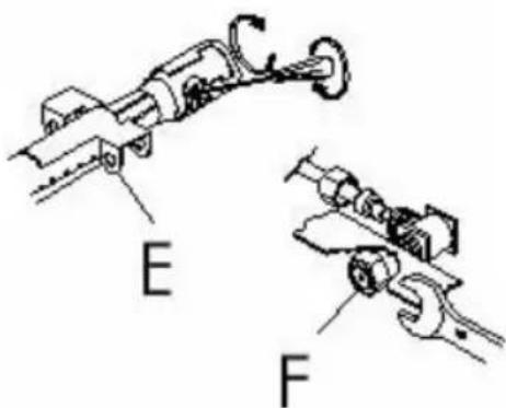
Fig. 5-6
Fig. 9
ENCENDIDO DEL HORNO A GAS
natural_image
Technical line drawing of a microwave oven with labeled component A, showing internal structure and mounting base (no text or symbols beyond label)ENCENDIDO DEL HORNO NO DOTADO DE ENCENDIDO ELECTRONICO (Fig. 10)
natural_image
Technical line drawing of a mechanical device with no visible text or symbolsDESMONTAJE DE LA PUERTA DEL HORNO
natural_image
Technical line drawing of a mechanical assembly with no visible text or symbols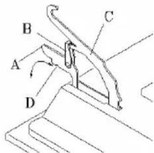
Fig. 16
natural_image
Technical line drawing of an open refrigerator with internal compartments and labeled parts (no text or symbols beyond label)LIMPIEZA Y CUIDADO
natural_image
Line drawing of a hand using a screwdriver to press or install an electronic device (no text or symbols present)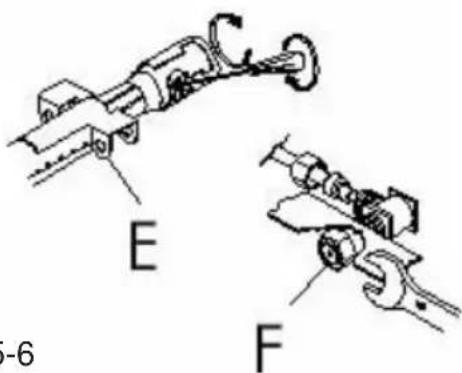
fig. 5-6
Fig. 9
ACCENSIONE DEL FORNO A GAS
natural_image
Technical line drawing of a mechanical device with adjustment knobs and a labeled section (no text or symbols on the diagram itself)SMONTAGGIO DELLA PORTA FORNO
natural_image
Technical line drawing of a door frame with internal compartments and mounting holes (no text or symbols)Fig. 16
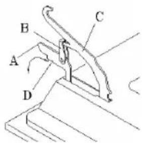
Fig. 17
natural_image
Technical line drawing of a microwave oven with internal compartments and mounting holes (no text or symbols)PULIZIA E CURA
Thank you for choosing one of our products. We hope it will offer you many years of excellent performance. Please carefully read the instructions and suggestions contained in this manual for correct use of our products. The manufacturer declines all liability for injury to persons or damage to things due to incorrect or inappropriate installation of the appliance. The manufacturer reserves the right to make any changes it considers necessary to its products without notice.
IMPORTANT: during operation, the front panel and glass door panel become very hot. Do not allow children to play near the oven.
CAUTION
This appliance can be installed and can operate only in permanently ventilated rooms in compliance with UNI 7129/UNI 7131 (fig. 2 pag. 2).
All maintenance must be performed by qualified personnel with the oven disconnected from the electricity supply and the gas tap closed.
N.B. In the slot-in units, all veneered plastic strips and sheets must be glued using heat-resistant adhesives (120°C).
INSTRUCTIONS FOR INSTALLATION PERSONNEL
The appliance must be installed by the purchaser and any work required by the manufacturer as a result of incorrect installation will not be covered by the warranty. All installation and adjustment operations must be performed by skilled personnel with specific technical and professional qualifications who, when they have finished, are required to issue a declaration certifying conformity of the work carried out. Said personnel will also be responsible for any injury to persons or damage to things caused by connections that do not comply with current regulations.
This appliance complies with the EEC circular 82/499 concerning limitation of radio interferences. The parts of the oven that come into contact with the food comply with the EEC Directive 89/109.
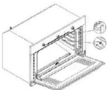
FITTING IN THE UNIT (fig. 1 - pag. 1)
All installation operations must be performed by qualified personnel.
- The appliance can be fitted below the work top or in a column unit. In both cases the dimensions specified in Table 1 must be observed.
- The oven is fitted in the unit as follows (fig. 1):
- take out the screws A to remove the surround covers;
- connect the oven to the electricity and gas supply and slide it into the unit;
- secure the oven to the unit by means of 4 wood screws B;
- refit the surround covers.
- Do not use the door as a lever when installing the oven.
- Do not exert pressure on the oven door when it is open.
CAUTION: do not obstruct cooling or fume discharge apertures or vents.
INSTALLATION PREMISES (fig. 2 - pag. 2)
For correct operation of the appliance, sufficient natural ventilation must be provided in the room for combustion of the gas.
Installation personnel must follow the safety regulations in force in the country (UNI-CIG 7129 and 7131). The room must be ventilated directly via inlets on the outside walls (fig. 2).
These inlets must have a free section of at least 100 cm^2 (one or more inlets can be provided).
Combustion products must be discharged by means of extractor hoods connected to the flue or directly to the outside (fig. 2).
If it is not possible to install an extractor hood, an electric fan must be fitted either to the outside wall or the window; the room must be provided with ventilation inlets in compliance with current regulations. The fan flow rate must be able to guarantee an hourly exchange of air 3-5 times the volume of the kitchen
CONNECTION
At the bottom of the oven surround you will find a rating plate specifying the gas used for calibration. If you are using exactly the same type of gas, carefully follow the connection instructions. If not, the oven must be adapted to the type of gas available before following the connection instructions.
Connection instructions (fig. 3)
The appliance must be connected to the gas supply by means of a rigid metal pipe or a metal hose in compliance with the regulations in force in the country (UNI 9891).
The connection between the gas ramp coupling and the pipe must be made as follows:
-
tapered fitting (ISOR7) with seal on thread plus addition of suitable sealing agent;
-
by fitting an approved sealing gasket (aluminium, copper, rubber) in-between.
WARNING: application of a rubber hose to the hose fitting is not allowed because it cannot be inspected.
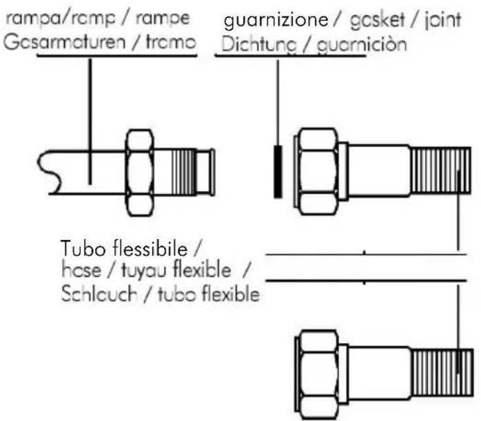
Fig. 3
Caution: once you have finished the operation, check that there are no gas leaks by testing with soapy water or equivalent. DO NOT USE FLAMES TO TEST FOR GAS LEAKS.
natural_image
Line drawing of a hand holding a screwdriver above a device component (no text or symbols)GB - The appliance is supplied with cable without plug. A standardised plug must be used bearing in mind that:
- yellow - green = earth
- blue = neutral
- brown = phase
ELECTRICAL CONNECTION
Before connecting the appliance to the mains, ensure that:
- The voltage corresponds to the voltage specified on the rating plate at the bottom of the surround.
- The overload cut-off device and the domestic system can withstand the load of the appliance (see rating plate).
- The power supply system is provided with an efficient earth connection and that the socket or omnipolar switch, with minimum contact opening of 3mm., is easily accessible once the appliance has been installed.
- If the plug is not easily accessible, the installation personnel must provide an omnipolar switch with contact opening distance equal to or greater than 3 mm.
The power supply cable must be positioned so that it does not at any point exceed the ambient temperature by 50^ C.
CHANGING THE OVEN BURNER INJECTOR (fig. 5-6)
-
Ensure that the oven is electrically disconnected;
• fully open the oven door;
• take the bedplate out (fig. 5);
• slide the burner out as follows: -
take the diffuser element C out, removing the nuts D;
- move the plug holder bracket E plus thermocouple;
- remove the screw B and slide out the burner tube;
- remove the injector F with a 7 mm spanner and replace it following the instructions in table 2 (the injector must be locked to prevent it sliding out).
• refit the oven burner performing the above oprations in reverse order;
- replace the bedplate.
Pay particular attention to the plug wires and thermocouple tubes.
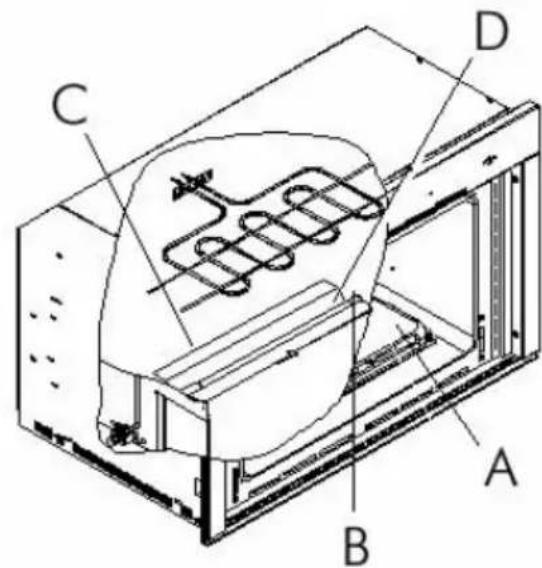

Fig. 5-6
ADJUSTING THE BURNER AIR (fig. 7-8)
Due to the characteristics of the different types of gas used, the flame may have too little or too much air. In this case adjustment must be performed as follows:
- Loosen the screw C on the burner
- turn the ring nut D to position N for methane or natural gas and to position G for liquid gas so that the moving reference mark on the ring nut coincides with the fixed reference mark on the burner, thus obtaining a regular flame (fig. 8).
Examples:
a) Flame with too much air, small and thin: turn the ring nut D to reduce the distance X (anticlockwise).
b) Flame with too little air, irregular with yellow tips: turn the ring nut D to increase the distance X (clockwise).
c) Normal flame: blue colour.
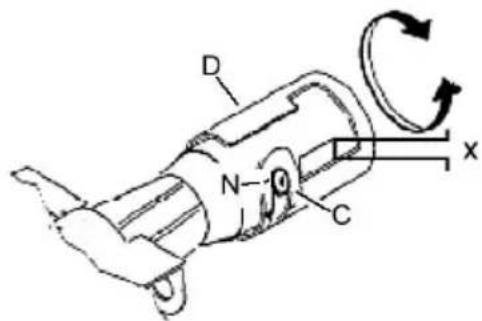
Fig. 7
eccesso d'aria / too much air / exces d'air zuviel Luft / exceso de aire
fiamma regolare / regular flame / flamme régulière / reguläre Flamme / llama regular
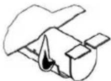
Fig. 8
mancanza d'aria / not enough air / manque d'air / zuwenig Luft / falta de aire
ADJUSTING THE THERMOSTAT MINIMUM SETTING
This operation is performed with the oven in the unit and after the electrical and gas connections have been made by qualified personnel. The operation is necessary when switching from one type of gas to another (from natural gas G20 to liquid gas G30) in order to guarantee a minimum temperature of around 150^ C.
Sequence with metal dashboard
- open the oven door (the burner will ignite only with the door open);
- remove the bedplate (base) of the oven;
• operate the oven at maximum temperature for at least 20÷30 minutes;
• once the oven is on, close the door; - reset the thermostat knob to 150^ ;
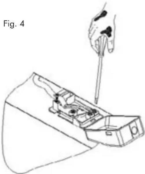
- remove the knob A (fig. 9);
- insert a screwdriver into hole B parallel with the thermostat shank and adjust the by-pass until you obtain a reduced but stable flame. This operation must be performed with the oven door closed.
- Use a flat blade screwdriver (fig. 9) to adjust the by-pass screw. Simply unscrew the by-pass to adjust the minimum setting when switching from liquid gas to methane.
- For operation with G30/G31 (LPG) the by-pass adjustment screw must be fully tightened.
IMPORTANT:
after adjusting the burner, check that the flame is maintained at minimum setting as follows:
- turn the knob from min. to max. 2-3 times;
- open and close the oven door continuously (neither too fast or too slowly);
- if the flame goes out, adjust the by-pass setting (slightly increase the minimum setting).
- Once you have finished (replacement of injector, adjustment of air and minimum setting), switch the oven off and affix the new rating plate (indicating the gas used).
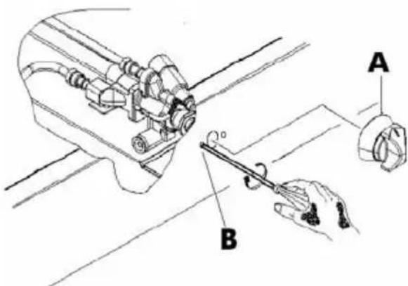
Fig. 9
SWITCHING THE GAS OVEN ON
The oven is switched on with the DOOR OPEN as follows:
- press the thermostat knob A (fig. 10) slightly and turn it anticlockwise to maximum.
Press knob A right in to trigger the electric ignition and keep it pressed for a few seconds to activate the safety device - set the knob to the required temperature.
Check, through the apertures at the front of the oven plate, that the oven burner has ignited and ensure that when the thermostat knob is released, the burner flame remains on. If not, repeat the operation.
Always check perfect operation of the burner with the door closed.
SWITCHING ON THE OVEN WHEN NOT PROVIDED WITH ELECTRONIC IGNITION
If the ignition does not work or the oven is not provided with ignition device, use a match or gas lighter to light the oven via the ignition hole at the front of the bedplate at the same time pressing the thermostat knob right in, turned anticlockwise to maximum; keep it pressed for a few seconds to activate the safety device and then set the knob to the required temperature.
USING THE ELECTRIC GRILL (Fig. 11) SYMBOLS
Pos. 0
OFF
Pos. 1

OVEN LIGHT
Pos. 2

SPIT
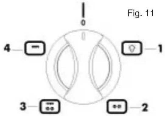
Switch the gas oven on and set the thermostat knob to between 150°C and 270°C. The oven door must be closed.
Pos. 3

GRILL + SPIT
This type of cooking allows you to brown the food. The oven door must be kept open and the knob protection fitted. With the selector in this position, the grill and spit automatically operate together.
Pos. 4

CENTRAL GRILL
This type of cooking is particularly suitable for quick browning. The oven door must be kept open and the knob protection fitted.
WARNING:
If the oven thermostat knob is accidentally turned during operation of the electric grill, a safety device will prevent operation of the grill. To restore operation, simply turn the oven knob until the moving reference mark coincides with the fixed reference mark on the front panel (closed). frontale (chiuso).
USING THE ELECTRIC GRILL SELECTOR
Turn the knob to the required function.
You are advised to pre-heat the grill for 5 minutes.
Place the food to be grilled on the rack or in a low-sided baking tin. The rack must be positioned as high as possible (according to th volume of food to be cooked) with the dripping pan below. For this type of cooking the oven door must be kept open and then partially closed. The food must be turned so that both sides are evenly grilled, depending on what you are cooking (e.g. meat, fish, poultry, etc.).
The grill must not be used for more than 30 minutes.
CAUTION: the grill does not work when the oven gas function is switched on.
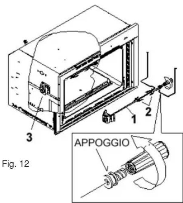
USING THE SPIT (fig. 12)
Slide the food onto the spit rod (1) between the two forks (2), securing it in a stable position by means of the forks to prevent straining the motor. Fit the spit rod into the spit motor (3) and rest it on the support provided. Place the collecting plate on the lowest shelf. Switch the grill on (knob C, position 2).
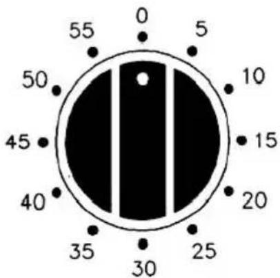
PROGRAMMING YOUR OVEN WITH THE 60 MINUTES TIMER (fig. 13)
The regulating knob must be turned in a clockwise direction until it reaches the 60 minutes position and then turned to the desired time by turning the knob in a counter clockwise direction.
The oven will not be turned off automatically.
A minute counter ringing will advise that the cooking time is over.
Fig. 13
MAINTENANCE
Damaged parts must be replaced by the Technical Support service. You are also advised to have the appliance serviced by the Technical Support department approximately once a year.
IMPORTANT:
You are also advised to periodically check the gas connection pipe and immediately replace it if not in perfect condition.
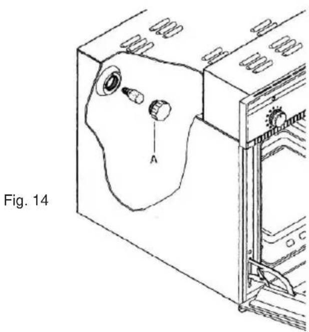
REPLACING THE OVEN BULB
If it is necessary to replace the oven light bulb, remove the protective cover A by unscrewing it anticlockwise. After replacing the bulb, refit the protective cover A (fig. 14).
natural_image
Technical line drawing of a mechanical device with labeled component A, showing internal components and mounting brackets (no text or symbols beyond label)REMOVING THE OVEN DOOR
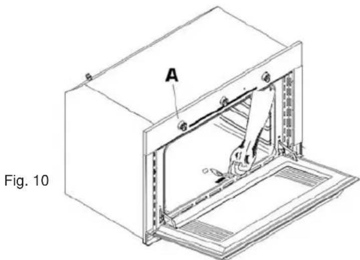
To facilitate cleaning of the oven, the door can be removed as follows:
Hinges with moving bolts (fig. 16)
The hinges
A are provided with two moving bolts
B which lock the door in the open position when connected to elements
C. The door must then be raised and pulled out; to do this, grip the sides of the door near the hinges. To refit the door, first slide the hinges into their grooves
D and then close the door. DO NOT forget to lower the two moving bolts B used to prop the door open.
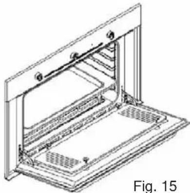
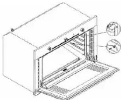
The glass door panel can be easily removed by unscrewing the 4 side screws (fig. 15).
N.B.: the screws must not be fully tightened as this can damage the gasket.
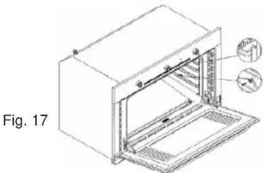
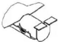
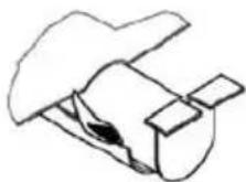
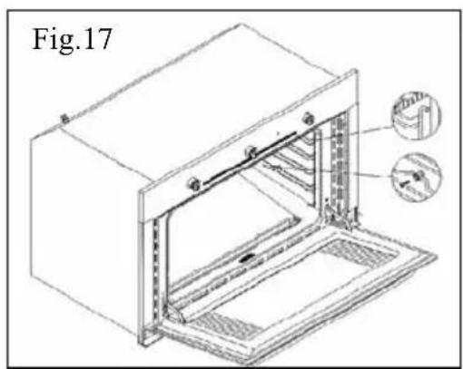
Accessories provided with the oven
The appliance can be provided with runners which must be hooked to the oven wall. Slide the racks and tray provided into the runners.
To remove the runners, simply press down (fig. 17).
TECHNICAL SUPPORT
If the appliance is not working properly, you are advised to check the following before calling the Technical Support service:
check that the appliance is correctly plugged in;
check that the gas flow is regular and that the pipe is not kinked or interrupted.
natural_image
Technical line drawing of a mechanical assembly with no visible text or symbolsFig. 16
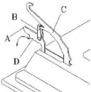
Fig. 17
natural_image
Technical line drawing of a microwave oven with internal structure and mounting base (no text or symbols)CLEANING AND CARE
Disconnect the appliance from the electrical supply before any operation. The enamelled or painted parts must be cleaned every time the oven is used.
Wait for the oven to cool and clean it with warm water and a non-corrosive detergent. Never use knives, steel wool etc. Make sure that fat does not deposit on the walls as this will produce unpleasant smells when the oven is next used. Both the door and glass panel can be removed to facilitate certain cleaning operations.
INSTRUÇÕES PARA O UTENTE
natural_image
Line drawing of a hand using a tool to lift a component into a device (no text or symbols)LIGAÇÃO ELÉCTRICA
natural_image
Technical line drawing of a microwave oven with labeled component A, showing internal structure and mounting base (no text or symbols beyond label)natural_image
Technical line drawing of a mechanical device with labeled components and a directional arrow (no text or symbols beyond label)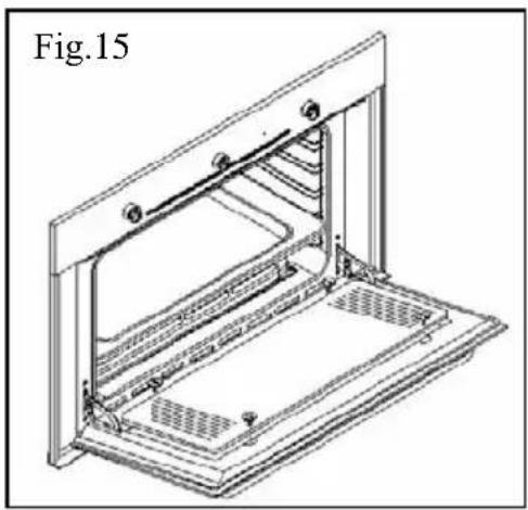
natural_image
Technical line drawing of an open refrigerator with internal compartments and ventilation slots (no text or symbols)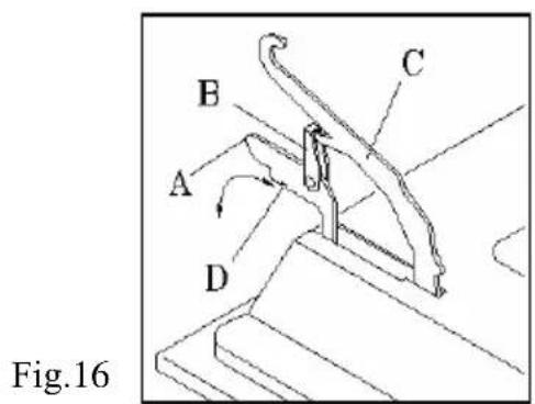
DESMONTAGEM DA PORTA DO FORNO
- CONEXIÓN ELÉCTRICA
- ENCENDIDO DEL HORNO A GAS
- ENCENDIDO DEL HORNO NO DOTADO DE ENCENDIDO ELECTRONICO (Fig. 10)
- DESMONTAJE DE LA PUERTA DEL HORNO
- LIMPIEZA Y CUIDADO
- ACCENSIONE DEL FORNO A GAS
- SMONTAGGIO DELLA PORTA FORNO
- PULIZIA E CURA
- CAUTION
- INSTRUCTIONS FOR INSTALLATION PERSONNEL
- FITTING IN THE UNIT (fig. 1 - pag. 1)
- INSTALLATION PREMISES (fig. 2 - pag. 2)
- CONNECTION
- Connection instructions (fig. 3)
- ELECTRICAL CONNECTION
- CHANGING THE OVEN BURNER INJECTOR (fig. 5-6)
- ADJUSTING THE BURNER AIR (fig. 7-8)
- Examples:
- ADJUSTING THE THERMOSTAT MINIMUM SETTING
- Sequence with metal dashboard
- IMPORTANT:
- SWITCHING THE GAS OVEN ON
- SWITCHING ON THE OVEN WHEN NOT PROVIDED WITH ELECTRONIC IGNITION
- USING THE ELECTRIC GRILL (Fig. 11) SYMBOLS
- WARNING:
- USING THE ELECTRIC GRILL SELECTOR
- USING THE SPIT (fig. 12)
- PROGRAMMING YOUR OVEN WITH THE 60 MINUTES TIMER (fig. 13)
- MAINTENANCE
- REPLACING THE OVEN BULB
- REMOVING THE OVEN DOOR
- Hinges with moving bolts (fig. 16)
- Accessories provided with the oven
- TECHNICAL SUPPORT
- CLEANING AND CARE
- INSTRUÇÕES PARA O UTENTE
- LIGAÇÃO ELÉCTRICA
- DESMONTAGEM DA PORTA DO FORNO
Brand : TEKA
Model : FG 824.3
Category : Oven