S-50 - Solarium Soltron - Free user manual and instructions
Find the device manual for free S-50 Soltron in PDF.


User questions about S-50 Soltron
0 question about this device. Answer the ones you know or ask your own.
Ask a new question about this device
Download the instructions for your Solarium in PDF format for free! Find your manual S-50 - Soltron and take your electronic device back in hand. On this page are published all the documents necessary for the use of your device. S-50 by Soltron.
USER MANUAL S-50 Soltron
natural_image
3D rendered mechanical component with curved and rectangular features (no text or symbols visible)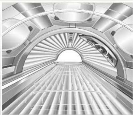
natural_image
Interior view of a modern, curved architectural space with radial lighting and grid-patterned flooring (no text or symbols visible)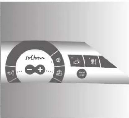
text_image
soliton - + ...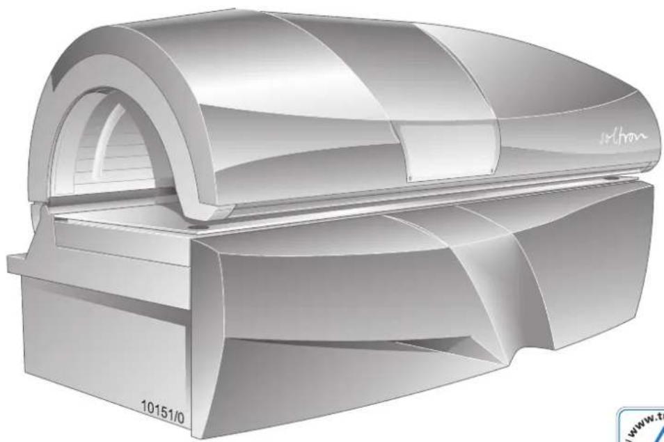
natural_image
3D rendered model of a cylindrical device with arched top and base, labeled '10151/0' (no text or symbols on the device itself)CE
6.3.5 S-55 TWIN POWER....71
6.3.6 S-55 TURBO POWER 72
natural_image
Recycling symbol with three arrows forming a triangle (no text or labels)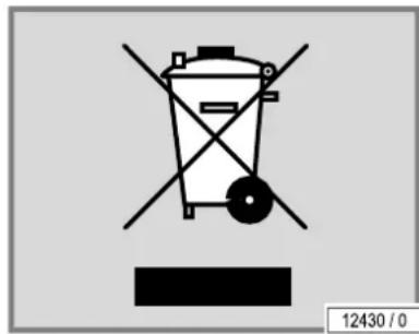
text_image
12430 / 0text_image
Technical diagram of an air conditioner unit with numbered parts and a magnified view of the internal structure.text_image
Technical diagram of a portable air conditioner unit with labeled components and airflow direction indicator13543 / 1
text_image
Diagram showing cable connection between two computer monitors with labeled components and connection point 13254/0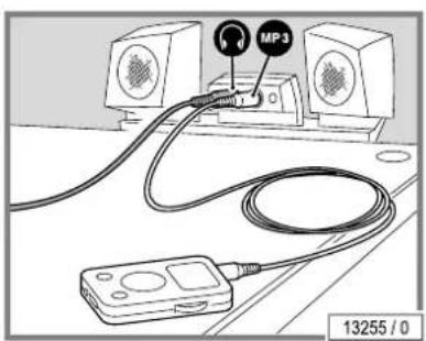
text_image
MP3 13255 / 0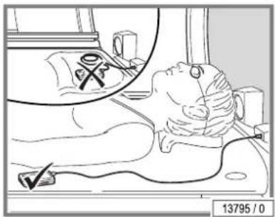
text_image
13795 / 0ACHTUNG!
text_image
Technical diagram of an air conditioner unit with numbered parts labeled 1 through 7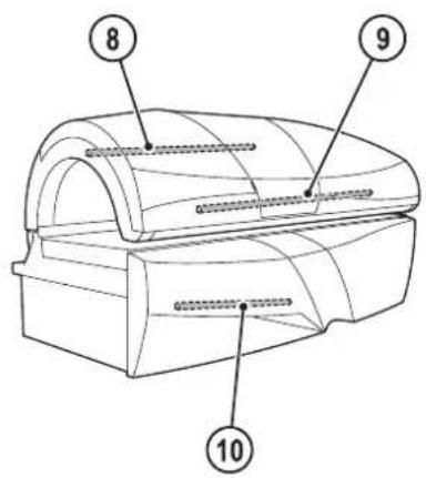
text_image
8 9 1014095/0
natural_image
Technical line drawing of a mechanical component with no visible text or symbolsnatural_image
Diagram of a mechanical device with directional arrows indicating motion or flow, no readable text or symbols present.natural_image
Line drawing of a mechanical device with an open lid and internal structure, no text or symbols presentnatural_image
Technical line drawing of a mechanical component with an arrow indicating direction (no text or symbols)natural_image
Illustration of two workers installing or adjusting a large cylindrical device (no text or symbols visible)natural_image
Illustration of two workers installing a large cylindrical object with a fan blade, no text or symbols presentnatural_image
Technical line drawing of a mechanical component with no visible text or symbols5.7.3 Wanne öffnen
natural_image
Technical line drawing of a mechanical component with a control knob and scale indicator (no text or symbols)natural_image
Diagram of a cylindrical object with a dashed line and arrow indicating direction, labeled '12557 / 0' (no text or symbols on the object itself)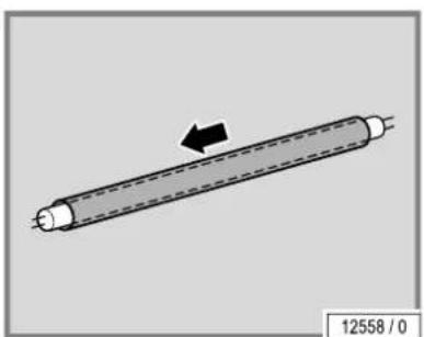
natural_image
Diagram of a cylindrical object with a dashed line and arrow indicating direction, labeled '12558 / 0' (no text or symbols on the object itself)natural_image
3D diagram of a cylindrical mechanical component with directional arrows indicating rotation (no text or symbols)natural_image
Technical line drawing of a mechanical component with a hexagonal nut and directional arrow (no text or symbols)natural_image
Technical line drawing of a mechanical component with a control knob (no text or symbols)natural_image
Technical illustration of a mechanical assembly with an inset showing a hand holding a component (no text or symbols present)- Filter entnehmen.
natural_image
Grid pattern with a small smiley face at the top (no text or symbols)natural_image
Diagram of a car interior showing structural components and airflow direction (no text or symbols)GEFAHR!

natural_image
Simple 3D rectangular block diagram with no text or symbols on the shape itselfnatural_image
Technical line drawing of a mechanical device with two arrows indicating features (no text or symbols)ACHTUNG!

natural_image
Technical line drawing of a mechanical component with a hexagonal nut and directional arrow (no text or symbols)natural_image
Diagram of a 3x3 grid layout with no text or symbols, labeled '13281 / 0' at bottom right (no other text or symbols)natural_image
Line drawing of a white industrial machine with a mesh cover and ventilation slots (no text or symbols)natural_image
Grid pattern with uniform square cells, no text or symbols presentnatural_image
Line drawing of a server rack unit with ventilation grilles and ventilation ducts (no text or symbols)natural_image
Technical line drawing of a mechanical component with a hexagonal dial indicator (no text or symbols)natural_image
Technical line drawing of a mechanical component with no visible text or symbolsnatural_image
Technical line drawing of a mechanical component with no visible text or symbolsDesign Peach Party / Design Queen Berry
natural_image
Illustration of a silver electric shock absorber with control panel and display (no text or symbols)MCS IV plus
natural_image
Illustration of a silver industrial machine with control panel and buttons (no visible text or symbols)MCS VI plus
natural_image
Illustration of a silver industrial machine with control panel and display (no visible text or symbols)Studiopilot
text_image
Technical diagram of a mechanical device with numbered components and directional arrows indicating motion or assembly.1: Typenschild
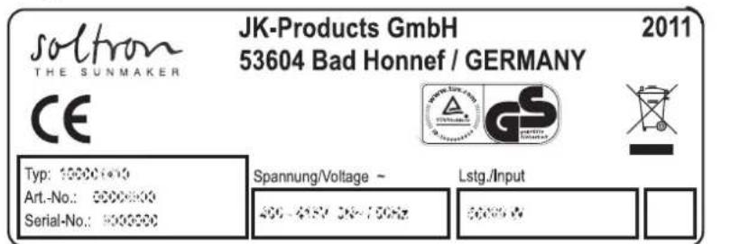
text_image
soltron THE SUNMAKER JK-Products GmbH 53604 Bad Honnef / GERMANY 2011 CE Typ: 10000+00 Art.-No.: 0000000 Serial-No.: 1000000 Spannung/Voltage ~ 400~450V 3K~750Hz Lstg./Input 8000%14098/0
We emphasize that these devices must not be exported to or operated in the USA or Canada! The manufacturer does not accept any liability in case of non-observance of this notice.
REMARQUE
This sunbed must be checked and serviced at regular intervals in accordance with the manufacturer's specifications in order to rule out entirely any risk of physical injury. Label wording = "Date of manufacture ... quarter/year"
natural_image
3D rendering of a modern cylindrical device with curved top and side panels, labeled '10151/0' (no text or symbols on the device itself)CE
Operating instructions
Translation of the original operating instructions
S-50 | S-55
S-50 SUPER POWER
S-50 TWIN POWER
S-50 TURBO POWER
S-55 SUPER POWER
S-55 TWIN POWER
S-55 TURBO POWER
1005350-01 / en / 11.2011
Imprint
Manufacturer: JK-Products GmbH
Rottbitzer Straße 69
53604 Bad Honnef (Rottbitze)
GERMANY
Tel.: +49 (0) 22 24 / 818-140
Fax: +49 (0) 22 24 / 818-166
Customer service / JK-International GmbH,
Technical service Division JK-Global Service
(Spare part orders for Rottbitzer Straße 69 components): 53604 Bad Honnef (Rottbitze)
GERMANY
Tel.: +49 (0) 22 24 / 818-861
Fax: +49 (0) 22 24 / 818-205
E-mail: service@jk-globalservice.de
Spare part orders for JK-International GmbH, consumables: Division JK-Licht
Failure to observe these instructions:
• can result in serious injury and death,
- can result in damage to the device and the environment.
- Read these instructions carefully before putting this tanning device into operation.
- Please observe the instructions and the code of conduct required to operate the device safely.
- Please make the instructions and additional information from the manufacturer available to the personnel at their workplace.
Copyright
The copyright remains with JK-Holding GmbH.
The contents may not be partially or completely duplicated, distributed or utilized for competition purposes without authorisation or disclosed to other parties.
The right to make technical changes in regard to the figures and information contained in this instruction manual is reserved!
Table of contents
1 General....6
1.1 Definitions 6
1.2 Symbol explanation....7
2 Information for the operator....8
2.1 Intended use 8
2.2 Foreseeable misuse....8
2.3 Operator's obligations 8
2.4 Personnel training 9
2.5 Scope of delivery....9
2.6 Transport, assembly and setup....9
2.6.1 Assembly 10
2.6.2 Ventilation 10
2.6.3 Setup location 11
2.7 Commissioning....11
2.8 Operation and maintenance....11
2.9 Decommissioning....12
2.10 Storage 12
2.11 Disposal 12
2.11.1 Environmental regulations – disposal of lamps and batteries ..... 12
2.11.2 Packaging 12
2.11.3 Disposal of old devices 12
2.12 Directives 13
2.13 Export....13
2.14 MP3 music (optional) 13
2.15 Instruction signs on the device 14
2.16 Technical modifications....14
2.17 Manufacturer's guarantee 14
2.18 Warranty and liability exclusions.... 15
3 Description 16
3.1 Scope of delivery....16
3.1.1 Optional....16
3.2 Equipment....16
3.3 Device description....17
3.4 Accessories (optional)....18
3.5 Functional description 18
4 Operation....19
4.1 Safety information for the user 19
4.2 Tanning - the right way! 21
4.3 Description of the skin types .....22
4.4 Tanning times EN....23
4.5 Tanning times UV type 3 (apply only to Austria) .....26
4.6 Tanning times IEC....31
4.7 Operating overview 35
4.8 Functions....36
4.9 Start....37
4.10 Connect MP3 player....37
5 Cleaning and maintenance....39
5.1 Safety instructions when undertaking cleaning or maintenance work 39
5.2 Faults....40
5.3 Cleaning 40
5.3.1 Cleaning the surfaces....40
5.3.2 Filter panels and lamps 41
5.4 Cleaning plan 41
5.5 Maintenance....42
5.5.1 Acrylic glass 43
5.6 Maintenance plan....43
5.7 Cleaning and maintenance work preparation 45
5.7.1 Lift up the acrylic glass panel and remove the partition.....45
5.7.2 Remove the canopy panel....46
5.7.3 Open the bed base....47
5.8 Instructions for replacing the lamps....48
5.8.1 Low pressure lamps 48
5.8.2 Makrolon tubes....49
5.8.3 Starter....50
5.8.4 High pressure lamps and filter panels 50
5.9 Cleaning or replacing UV lamps in the base 52
5.10 Cleaning or replacing UV lamps and filter panels in the canopy 52
5.11 Cleaning or replacing the interior lights ....53
5.12 Cleaning or replacing the front panel accent lighting....54
5.13 Cleaning the filter in the base....54
5.14 Cleaning the air intake openings....55
5.15 Cleaning the canopy filter mats 55
5.16 Air conditioning: Empty the condensation tank and clean the filter 56
5.17 AVS AROMA VITALIZER system maintenance....58
5.17.1 Changing the AROMA canister ....59
5.17.2 Replacing the VITALIZER canister....60
6 Technical data....62
6.1 Power, connection rating and noise level....62
6.2 Dimensions 65
6.3 Lamp sets 66
6.3.1 S-50 SUPER POWER....66
6.3.2 S-50 TWIN POWER....67
6.3.3 S-50 TURBO POWER 68
6.3.4 S-55 SUPER POWER....69
6.3.5 S-55 TWIN POWER....70
6.3.6 S-55 TURBO POWER 71
6.3.7 Accent lighting....72
6.4 Spare parts and accessories....73
7 Appendix....74
7.1 JK timer controls 74
7.2 Signs and stickers on the device....75
7.3 Equivalence key range....78
7.3.1 Description of the equivalence keys for UV fluorescent lamps....78
8 Index....80
1 General
1.1 Definitions
Operator
People who provide tanning devices to users on a commercial basis. The operator is responsible for the orderly operation of the device as well as the compliance with the maintenance intervals.
User
A person who uses the tanning device at a commercial location.
Personnel
People who are responsible for the operation, cleaning as well as general maintenance work and who instruct the users in the operation of the devices.
Electrician
A person with suitable professional training, knowledge and experience, which enables them to identify and avoid the dangers which can arise from working with electricity.
Authorized, trained and qualified personnel
Qualified personnel from an external company who have been trained and authorized by the manufacturer for assembly and maintenance work with specific tanning devices.
1.2 Symbol explanation
The following types of safety notices are employed in these operating instructions:
DANGER!

Type and source of hazard
This safety notice indicates the existence of a direct danger to body and life.
DANGER!
Type and source of hazard
This safety notice warns of dangers to body and life which are caused by electricity.
WARNING!

Type and source of hazard
This safety notice warns of machine, material or environmental damage.

NOTE:
This symbol does not identify any safety notices, but provides additional information to better understand the processes.
2 Information for the operator
2.1 Intended use
This device serves the purpose of cosmetic tanning for one adult person with skin suitable for tanning. Additional information is available on pages 19 and 22.
The device is only intended for commercial use, not for domestic use.
Some people are not permitted to use the device, see page 19.
The device may not be used by people with reduced physical, sensory or mental capabilities or who have insufficient experience and/or knowledge without supervision. A person responsible for their safety must ensure, either by supervision or instruction, that the device is used correctly and safely. If there is any doubt, use of the device by these people is prohibited!
The device may only be operated with the specified or equivalent lamps. The tanning times given in this instruction manual are valid only for the specified lamp set.
Any other use shall be considered improper. The manufacturer cannot be held liable for damage or injuries resulting from this. The operator bears the sole risk for this.
Intended use also includes compliance with the manufacturer's instructions and the operating and maintenance conditions. The device may only be operated, maintained and repaired by persons who are familiar with these tasks and who have been informed of the dangers involved.
2.2 Foreseeable misuse
The following uses of the device are explicitly prohibited:
- Multiple people may not use the device at the same time. The acrylic glass panel may otherwise break and cause injuries.
- People with a body weight of more than 135 kg may not use the device. The acrylic glass panel may otherwise break and cause injuries.
- Exceeding the specified tanning times may result in burns and long-term skin damage.
- When the device is in use no other people may remain in the cabin, in particular no children.
• People under 18 years of age may not use the device.
2.3 Operator's obligations
As the operator you are responsible for providing clear operating, cleaning and maintenance instructions and ensuring the intended use and the proper operation of the device by means of training and instruction for the personnel.
Your operating instructions must enable the safe use and safe operation of the device and take into account the characteristics and expertise of your company and also the national work safety and environmental protection regulations. Within the European Union, the EU directive 89/391/EEC (in Germany the Ordinance on Industrial Safety and Health (BetrSichV)).
2.4 Personnel training
As the operator you are obliged to train your personnel and instruct them in the established legal and accident prevention regulations. Ensure that your personnel have understood and observe these operating instructions. This applies in particular to the
• information in 'Intended use' and 'Foreseeable misuse'
• safety instructions in the 'Operation' chapter
- operating instructions
• cleaning and maintenance instructions
- Please make the instructions and additional information from the manufacturer available to the personnel at their workplace.
- Regularly check your personnel's safety consciousness and awareness of the risks, taking into account your operating instructions.
- Please ensure that the cleaning intervals are complied with, in particular cleaning after every tanning session.
- Please ensure that your personnel provide your customers with appropriate advice, in particular regarding tanning times, possible risks and the operation of the device.
- People under 18 may not use the device. Please instruct your personnel to check the customer's identification in the event of doubt.
2.5 Scope of delivery
Information regarding the scope of delivery is contained in the 'Description' chapter on page 16.
2.6 Transport, assembly and setup
The device is delivered by a specialist company and assembled and set up by the manufacturer's own service personnel or by an authorized service company.
As an operator you are responsible for complying with the on-site ventilation and electrical requirements at the setup location, see page 10.
2.6.1 Assembly
DANGER!

Personal danger due to electric shock or burns!
- The assembly and electrical connection must comply with the national regulations.
- The on-site electrical installation must be fitted with an easily accessible all-pole isolating device (master switch), complying with overvoltage category III. This means that each pole must have a contact opening width complying with the conditions of overvoltage category III for full isolation.
- If the connection is established via a plug-in connection then the connection system according to EN 60309 must be utilized.
- Assembly, installation, upgrading or repair of the device may only be carried out by specially trained and instructed personnel.
Information regarding the disassembly and assembly of the device is available in the separate assembly instructions. These assembly instructions are intended solely for use by the manufacturer's service personnel or by qualified specialists authorized by the manufacturer.
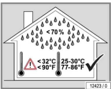
2.6.2 Ventilation
WARNING!

Risk of overheating due to air flow problems!
Operating faults possible.
- Do not change, obstruct or block the air inflow and outflow to the device or make any unauthorized changes to the device. The manufacturer shall bear no liability for damage or injuries resulting from such actions.
– Observe the ventilation system data. - Do not set up and operate the device on the transport pallet!
text_image
<70% <32°C 25-30°C 77-86°F 12423 / 0You can obtain data regarding the air supply and ventilation from the customer service department (see page 2).
text_image
12620 / 02.6.3 Setup location
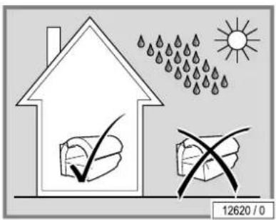
The tanning device may not be operated outside.
A conversion is required in order to operate the tanning device without problems at altitudes exceeding 2000 meters above sea level. Please contact the customer service department (see page 2) without fail before putting the tanning device into operation.
2.7 Commissioning
Initial commissioning will be undertaken by the manufacturer's own service personnel or by an authorized service company. The device will be handed over ready for use.
If the device has not been used for a longer period of time then it must first be inspected by our customer service department or by another authorized company before being put back into operation again.
The device is operated with an external time-control unit.
A time control unit must be attached so that the device automatically switches off at the latest after < 110 % of the selected running time even if the controller fails. The device running time must be provided with double protection by use of a timer control that complies with the standard EN 60335-2-27).
Dependent on the local utilities company, the devices can transmit interference to the power system of the building that impair the audio-frequency remote control system used by the utility company. This can, for example, interfere with the function of night-storage heaters.
If faults occur due to the operation of the devices, then the operator is responsible for the installation of an audio frequency blocking device in the building electrical installation. Please contact your electrician. The electrician is familiar with the technical connection conditions of your local utility company so that the audio-frequency blocking device can be matched to the power system of your utility company.
2.8 Operation and maintenance
Error-free operation, maintenance and service are required in order to ensure that the health and safety of the users is not endangered during operation and to ensure that the device is in a fault-free operating condition.
Please observe the information and recommendations provided in these operating instructions. Please ensure that the intervals for the inspection, maintenance and service are complied with. Please ensure that the lamps are replaced after the specified usage time.
Unauthorized modifications and changes to the device and its control unit are prohibited. Failure to comply with this voids the operating licence!
text_image
12427 / 02.9 Decommissioning
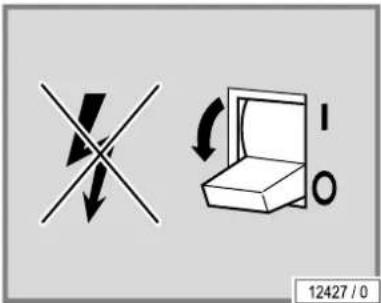
The device must be disconnected from the power supply in order to temporarily or permanently decommission it.
You must abide by the legal disposal requirements when permanently decommissioning the device.
2.10 Storage
Store the devices in a dry, frost-free location with a stable temperature. Once the device has cooled off, pack it in plastic wrapping to protect it against scratches.
2.11 Disposal
2.11.1 Environmental regulations – disposal of lamps and batteries
UV low pressure lamps contain fluorescent materials and other waste containing mercury. Batteries contain heavy metal compounds.
Within the European Union the national implementation of the Waste Framework Directive 2008/98/EC applies. According to the national waste disposal laws and in accordance with the municipal waste regulations, proof must be provided of the proper disposal of UV lamps and batteries.
Your local sales agency will be happy to assist you with the disposal of UV lamps and batteries:
- Inform your local agency of the number of UV lamps and batteries by telephone or in writing.
The agency will then provide you with the name of a free delivery point for your lamps or will take care, in conjunction with a disposal company, of the collection and proper disposal of the lamps. This service is available for a fee. Outside Germany, the respective national legislation applies. Please contact your local sales agency.
2.11.2 Packaging
All packaging consists of 100 % recyclable materials. Packaging brought into circulation by the JK Corporate Group that is no longer required can be returned to the JK Corporate Group. Your partner agency or dealer will be happy to advise.
2.11.3 Disposal of old devices
The device has been manufactured using recyclable materials. The JK Corporate Group will provide you with information on the content or potential hazards of the materials used.
The manufacturer is obliged to take back and dispose of certain electrical and electronic components in accordance with the 2002/96/EU Directive.
natural_image
Recycling symbol with three arrows forming a triangle (no text or labels)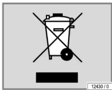
text_image
12430 / 0The components and devices are labelled with the following symbol:
The device will, if requested, be properly disposed of by the JK Corporate Group. This service is available free of charge. Your partner agency or dealer will be happy to advise.
2.12 Directives
This device was built according to the following directives:
- EC directive 'Electromagnetic Compatibility' 2004/108/EC (according to the version valid at the time)
- EC Machinery Directive 2006/42/EC (according to the version valid at the time)
- Low voltage directive 2006/95/EC (according to the version valid at the time)
2.13 Export
We emphasize that these devices are only intended for the European market and must not be exported to or operated in other countries e.g. the USA or Canada! The manufacturer does not accept any liability in the event of non-observance! We explicitly emphasize that non-compliance may result in high liability risks for the exporter and/or the operator.
2.14 MP3 music (optional)
text_image
JK GLOBAL SERVICE AUDIO-GUIDE SOUND SYSTEMS UK AUS NZ 1004450 11416 / 1If an MP3 player is used privately during tanning, then this does not constitute a public performance in the sense of copyright law, so that no reporting or fee obligation exists on the part of the studio operator towards the organisation responsible for issuing the commercial performance rights.
For the public use of MP3 music files, the same legislation applies as for all other music sources: As a studio operator/studio owner, you may only play original audio CDs, MCs, audio DVDs etc., on your premises and/or play music via the 'MP3-music modules' which are provided in the devices from JK-International GmbH if you have acquired the necessary stage rights. You can acquire these from the organisation responsible for issuing commercial performance rights in your country (in Germany: GEMA/GVL).
Copy-protected audio CDs, MCs, audio DVDs etc., as well as titles contained on these media, may not be converted to MP3 format and/or saved on HDD, audio CDs, MCs, audio DVDs etc., if software is used to do this, which disables or circumvents the copy-protection contained on the media.
You must be ready at any time to prove your granting of stage rights by presentation of the appropriate stage rights certificate when requested by a representative or another controlling body of the responsible organisation.
As long as you observe all the listed instructions and have acquired the necessary rights for use of the 'MP3-music module', you may convert your original audio CDs, MCs, audio DVDs etc. into the MP3 format required by the player. Only one copy (duplicate or MP3 format conversion) of lawfully acquired audio CDs, MCs, audio DVDs etc. may be made. The source media (original media) must be retained and may not be used simultaneously.
Further details can be found in the information brochure 'Audio Guide' available on the Internet at www.jk-global-service.de.

NOTE:
Pre-recorded SD cards which are delivered as accessories for a JK audio system are also subject to payment obligation for commercial usage.
2.15 Instruction signs on the device
See Appendix page 75.
2.16 Technical modifications
The device has been constructed in accordance with the current state-of-the-art and the applicable safety regulations. The illustrations and specifications on these instructions are subject to technical modifications which are required in order to improve the device.
Unauthorized modifications and changes to the device and its control unit are prohibited. Failure to comply voids the EC conformity declaration and the GS seal!
Please use only original spare parts. Failure to comply voids the EC conformity declaration and the GS seal!
2.17 Manufacturer's guarantee
JK-International GmbH accepts liability for any tanning device defects that arise in accordance with the following regulations on behalf of customers who have purchased an tanning device for private or commercial use from one of JK-International GmbH's sales partners; consumable parts such as UV high pressure lamps (bulb), UV low pressure lamps (tubes) and starters as well as the acrylic glass panel itself are not covered by the guarantee.
The guarantee stipulates that JK-International GmbH will rectify any defects within a time period predetermined by JK-International GmbH by repairing or exchanging the defective part.
Claims made in accordance with this guarantee can be lodged with JK-International GmbH or the JK-International GmbH sales partner from whom the product was purchased on presentation of the guarantee card or invoice; this guarantee is valid for a period of 24 months from the date of purchase.
This does not affect the rights of the customer under the existing guarantee with regard to any claims that the customer might have in accordance with the contract of purchase.
2.18 Warranty and liability exclusions
Warranty and liability claims for personal injury and property damage are excluded if they are the result of one or more of the following causes:
- improper use of the device;
- improper assembly, commissioning, operation and maintenance of the device;
- operating the device with faulty safety equipment or improperly attached or non-functional safety and protective equipment incl. warning signs;
- not complying with the information in the operating instructions regarding transport, storage, assembly, commissioning, operation and maintenance;
• the use of untrained personnel; - unauthorized changes to the device or the control unit;
• inadequate monitoring of parts subject to wear;
• repairs carried out improperly;
• the use of non-original spare parts; - emergencies and disasters resulting from the influence of foreign materials or force majeure.
3 Description
3.1 Scope of delivery
- Tanning device
- Suction cup for filter panels
- Connecting lead
- Headrest
- Protective goggles
- Allen-key
- Technical documentation (folder with instructions, brochures for error codes and default settings and additional documentation)
The low pressure UV lamps are delivered and packaged separately. They are only included in the scope of delivery and shipped together with the device in UV type 3 countries.
3.1.1 Optional
• Central exhaust air socket
- Audio system
• Air conditioning system
- Filter mats (canopy)
3.2 Equipment
Device equipment varies depending on the model.
In this description, all standard and optional components/functions are taken into account which must be observed during operation and/or when performing maintenance.
The control panel also differs according to the varying equipment:
Only those buttons are visible that can be operated, i.e. the corresponding function must be included in the device's equipment.
3.3 Device description
text_image
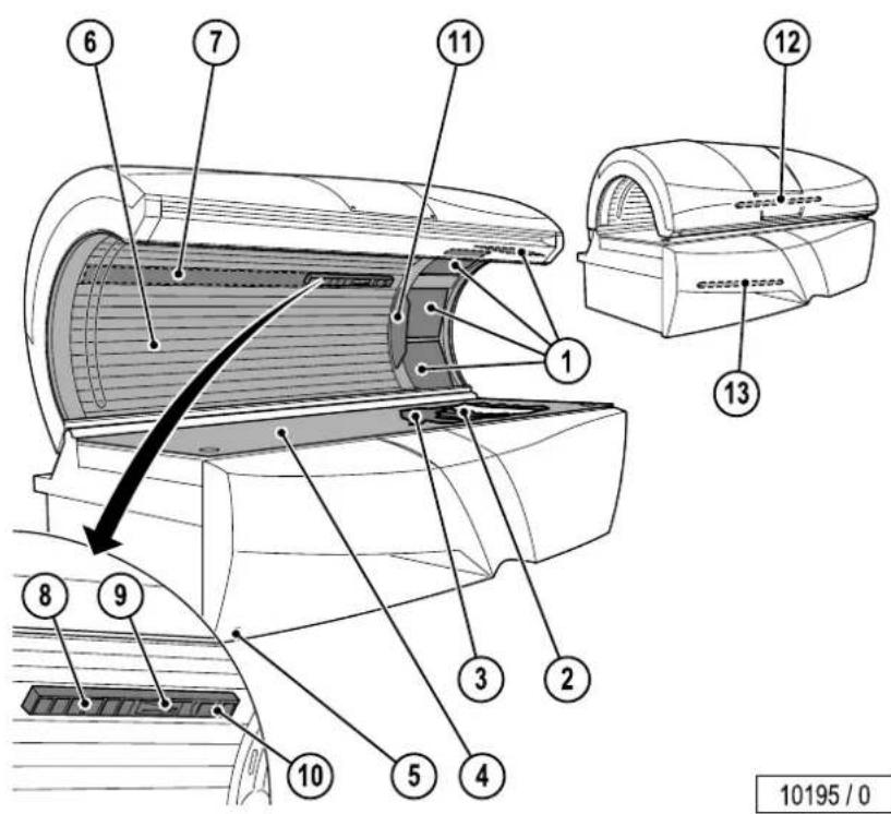
6 7 11 12 13 8 9 3 2 5 4 10 10195 / 0- Facial tanner (UV high pressure lamps)
- UV low pressure lamps, base
- Partition (only for devices with air conditioning)
- Acrylic glass panel base
- Infrared interface
- UV low pressure lamps, canopy
- Interior lighting
- Body cooling air jets
- VITALIZER nozzle
- Adjustable air jets – Facial cooling/AROMA
- Operating panel
- Accent lighting, canopy
- Accent lighting, front panel
3.4 Accessories (optional)
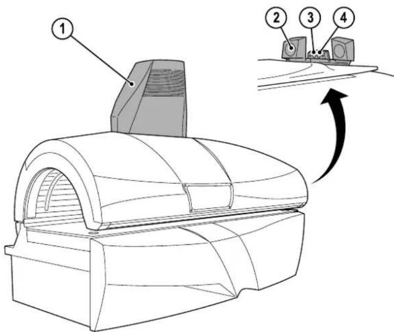
text_image
Technical diagram of a mechanical device with numbered components and directional arrow indicating motion or assembly.13543 / 1
- Central exhaust air socket
- Audio system
- Headphone connection
- MP3-connection
3.5 Functional description
The primary technical components of a tanning device are an artificial source of UV radiation, a variety of filters and reflectors as well as a mechanical structure with a defined active surface.
Different tanning results can be achieved in varying strength tanning devices. On one hand, this is due to the different strength UV lamps and, on the other hand, the different UV-A and UV-B proportions of the UV radiation. Whereas the UV-A proportion primarily generates a superficial tan, which appears rapidly and is intensive but also fades more rapidly, the UV-B radiation is primarily responsible for more long-term tanning results. The disadvantage of the UV-B radiation is that the tan does not become visible until one or two days after visiting the tanning salon. Therefore, the appropriate tanning device is to be selected depending on the desired tanning goal.
The tanning devices described here exclusively emit UV-A radiation.
4 Operation
4.1 Safety information for the user
DANGER!

Danger of hearing damage!
Using earphones or headphones at high volume can result in permanent hearing damage.
- Do not set the volume too high.
DANGER!

UV radiation
Danger of skin and eye injuries or skin diseases!
- Please observe the following instructions.
The following people may not use the device:
• People under 18 years of age
• People who cannot tan
• People who cannot tan in the sun without risking a sunburn
• People who easily sunburn when in the sun
• People with acute sunburn
• People who repeatedly suffered from serious sunburn during childhood
• People with naturally red hair
• People with atypically discoloured areas of skin
• People who have or have had skin cancer
- People who suffer from an increased risk of skin cancer (e.g. cases of skin cancer in the family)
• People among whose closest relatives a melanoma has occurred
• People who are being medically treated for photosensitivity
• People taking photosensitivity causing medicine
• People with freckles and people who tend to develop freckles
• People with more than 16 moles on their body (2 mm diameter or larger)
- People with atypical moles (atypical moles are, for example, asymmetrical moles with a diameter greater than 5 mm, with varying pigmentation and irregular edges)
- Seek medical advice without fail if in doubt!
All other people must observe the following instructions:
Danger of skin and eye injuries or skin diseases!
- The skin can become sunburnt when exposed to excessive radiation. Excessive, frequently repeated UV radiation exposure from natural sunlight or UV devices can result in premature ageing of the skin and an increased risk of skin tumours.
- Particular caution is advisable for individuals who are especially sensitive to UV radiation, and when certain medicaments or cosmetics are used. Seek medical advice without fail if in doubt!
- UV devices should not be used without medical advice if unexpected manifestations such as itching occur within 48 hours of first using the sunbed.
- Increasing tanning requires increased exposure time (= radiation time) or after a certain degree of tanning has been achieved, increased tanning is not possible. However, the radiation time may not be extended as desired within the scope of the permissible radiation doses! Therefore, only a certain level of final tanning, which depends on the skin type, can be achieved without endangering your health.
- The tanning device may never be used when a filter panel is missing or damaged, or the timer is defective!
Behaviour before, during and after a sunbath:
- During the tanning session no other people may remain in the cabin, in particular no children.
- Remove all jewellery (including piercings) before the tanning session.
- Remove cosmetics before tanning and do not use sun screen products.
- Do not use any products intended to accelerate tanning.
- UV light can cause irreversible skin or eye damage. The unprotected eye can become inflamed on the surface, and in certain cases the retina can be damaged by excessive radiation. Cataracts can form after numerous repeated tanning sessions. Use the UV-impermeable protective glasses provided (order no. 84592-..). Contact lenses and sun glasses are no substitutes for protective glasses.
- Protect sensitive skin areas such as scars, tattoos and genitals before tanning.
- Observe the recommended tanning times.
- During a tanning session the quantity of radiation which results in the skin reddening (MED, minimum erythema dose) may not be exceeded. If reddened skin occurs several hours after the tanning session you may not use the tanning device again for one week. After one week you can start again from the beginning with the first tanning session in accordance with the tanning table.
- The time between the first two sessions on the sunbed must be at least 48 hours! Do not take an additional sunbath on the same day.
- See a doctor if stubborn swelling, sores or pigmented moles form on the skin.
4.2 Tanning - the right way!
A few things need to be noted to in order to obtain maximum enjoyment from a tanning device. Here are some answers to frequently asked questions.
Make-up in the tanning device?
Please do not wear make-up. Clean skin absorbs UV light better.
A wide variety of materials is found in cosmetics. Whether these are emulsifiers, greases, or fragrances - in conjunction with UV radiation, these can cause skin allergy reactions.
Accordingly, a must before using a tanning device is: Remove all make-up. This is essential. Make-up clogs the pores in the face. The UV light from a tanning device re-opens these clogged pores so that not only does the light penetrate the skin, but also the allergenic components of the make-up.
A further negative consequence of make-up is that the appearance of the skin deteriorates irreversibly over a period of time. However good a decent make-up looks - in conjunction with UV light, it causes more harm than good. Therefore: Remove all make-up before a session in your tanning device - it will be much better applied afterwards.
Showering after leaving the tanning device?
The browning is in the skin, not on it. Therefore you cannot wash it off. Treat your skin to a moisturizing cream after showering.
Are medications and the tanning device compatible?
It is known that some medicaments increase the skin's sensitivity to UV light. This probability is particularly high with antibiotics, sulphonamides, psychiatric drugs, tranquillizers, anti-diabetes treatments and diuretics. Sun creams which contain psorale or kumarin also increase skin sensitivity. If you are in any doubt, first ask your doctor - then you can enjoy the sun at no risk.
Contact lenses in the tanning device?
The answer is: Yes! Like any other tanning device user, contact lens wearers should also wear special protective goggles which protect the eyes against UV radiation. To guarantee better protection, wearers of spectacles and contact lenses can ask their optician for exchange contact lenses with UV protection. The UV-A and UV-B filters built into exchange contact lenses will protect the cornea and the internal parts of the eye against almost 100 % of the energy in UV radiation.
This will benefit tanning device users not only in the open air, but on the tanning device itself. You can wear these contact lenses on the tanning device without any restrictions. For more information, ask your optician or optometrist.
4.3 Description of the skin types
DANGER!

Burns and long-term damage!
People with skin type I may not use the tanning device.
The following applies to people with skin types II, III and IV:
- Observe the tanning times.
- Observe the safety instructions.

NOTE:
The tanning times are only valid for the lamp set and filter panels specified on the sticker.
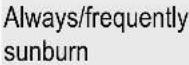
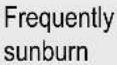
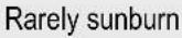
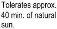
| Skin type I | Skin type II | Skin type III | Skin type IV |
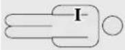 | 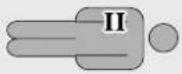 | 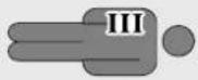 | 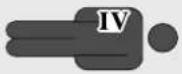 |
| Sensitive skin | Light skin | Normal skin | Dark skin |
 |  |  | 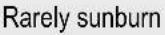 |
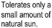 | 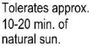 | 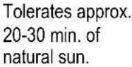 |  |
4.4 Tanning times EN
DANGER!

Burns and long-term damage!
People with skin type I may not use the tanning device.
The EN tanning times only apply to the EN lamp set (EN 60335-2-27, maximum irradiance 0.3 W/m^2 (erythema)).
S-50 SUPER POWER
- UV low pressure lamps Soltron TREND 100 W E3 1004344-..
- UV low pressure lamps Soltron TREND 120 W E4 1004520-..
S-55 SUPER POWER
- UV low pressure lamps Soltron TREND 100 W E3 1004344-..
- UV low pressure lamps Soltron TREND 120 W E4 1004520-..
| Number of tanning sessions | Skin type I Skin type II Skin type III Skin type IV | |||
| [min] | [min] | [min] | [min] | |
| 1 – 5 5 5 | ||||
| 2 – 10 10 10 | ||||
| 3 – 10 10 10 | ||||
| 4 – 11 11 11 | ||||
| 5 – 11 11 12 | ||||
| 6 – 12 12 14 | ||||
| 7 – 13 13 16 | ||||
| 8 – 14 14 18 | ||||
| 9 – 14 15 20 | ||||
| 10 – 14 16 22 | ||||
| 11 – 14 17 24 | ||||
| 12 + | – | 14 | 19 | 25 |
| Maximum number of tanning sessions per year (NMSC): | – | 100 | 71 | 56 |
DANGER!

Burns and long-term damage!
People with skin type I may not use the tanning device.
S-50 TWIN POWER
- UV low pressure lamps Soltron TREND 160 W E5 1005343-..
- UV low pressure lamps Soltron TREND 120 W E4 1004520-..
S-55 TWIN POWER
- UV low pressure lamps Soltron TREND 160 W E5 1005343-..
- UV low pressure lamps Soltron TREND 120 W E4 1004520-..
| Number of tanning sessions | Skin type I | Skin type II | Skin type III | Skin type IV |
| [min] | [min] | [min] | [min] | |
| 1 – 5 5 5 | ||||
| 2 – 10 10 10 | ||||
| 3 – 10 10 10 | ||||
| 4 – 11 11 11 | ||||
| 5 – 11 11 12 | ||||
| 6 – 12 12 14 | ||||
| 7 – 13 13 16 | ||||
| 8 – 14 14 18 | ||||
| 9 – 14 15 20 | ||||
| 10 – 14 16 22 | ||||
| 11 – 14 17 24 | ||||
| 12 + | - | 14 | 19 | 25 |
| Maximum number of tanning sessions per year (NMSC): | - | 100 | 71 | 56 |
DANGER!

Burns and long-term damage!
People with skin type I may not use the tanning device.
S-50 TURBO POWER
- UV low pressure lamps Soltron TREND 160 W E5 1005343-..
- UV low pressure lamps Soltron TREND 180 W E6 1003889-..
S-55 TURBO POWER
- UV low pressure lamps Soltron TREND 160 W E5 1005343-..
- UV low pressure lamps Soltron TREND 180 W E6 1003889-..
| Number of tanning sessions | Skin type I | Skin type II | Skin type III | Skin type IV |
| [min] | [min] | [min] | [min] | |
| 1 – 5 5 5 | ||||
| 2 – 10 10 10 | ||||
| 3 – 10 10 10 | ||||
| 4 – 11 11 11 | ||||
| 5 – 11 11 12 | ||||
| 6 – 12 12 14 | ||||
| 7 – 13 13 16 | ||||
| 8 – 14 14 18 | ||||
| 9 – 14 15 20 | ||||
| 10 – 14 16 22 | ||||
| 11 – 14 17 24 | ||||
| 12 + | - | 14 | 19 | 25 |
| Maximum number of tanning sessions per year (NMSC): | - | 100 | 71 | 56 |
4.5 Tanning times UV type 3
(apply only to Austria)
DANGER!

Burns and long-term damage!
People with skin type I may not use the tanning device.
The UV type 3 tanning times only apply to the UV type 3 lamp set (according to EN 60335-2-27, max. radiation intensity 0.15 W/m^2 UV-A + 0.15 W/m^2 UV-B).
S-50 SUPER POWER
- UV low pressure lamps Soltron TREND 100 W E3 1004344-..
- UV low pressure lamps Soltron TREND 120 W E4 1004520-..
| Number of tanning sessions | Skin type I | Skin type II | Skin type III | Skin type IV |
| [min] | [min] | [min] | [min] | |
| 1 – 6 6 6 | ||||
| 2 – 6 7 8 | ||||
| 3 – 7 8 10 | ||||
| 4 – 8 10 12 | ||||
| 5 – 9 11 14 | ||||
| 6 – 10 12 16 | ||||
| 7 – 10 14 18 | ||||
| 8 – 11 15 20 | ||||
| 9 – 12 16 22 | ||||
| 10 – 13 18 24 | ||||
| 11 – 14 19 26 | ||||
| 12 + | - | 15 | 21 | 28 |
| Maximum number of tanning sessions per year: | - | 63 | 45 | 34 |
DANGER!

Burns and long-term damage!
People with skin type I may not use the tanning device.
S-55 SUPER POWER
- UV low pressure lamps Soltron TREND 100 W E3 1004344-..
- UV low pressure lamps Soltron TREND 120 W E4 1004520-..
S-55 TWIN POWER
- UV low pressure lamps Soltron TREND 160 W E7 1005898-..
- UV low pressure lamps Soltron TREND 120 W E4 1004520-..
| Number of tanning sessions | Skin type I | Skin type II | Skin type III | Skin type IV |
| [min] | [min] | [min] | [min] | |
| 1 – 5 5 5 | ||||
| 2 – 5 6 6 | ||||
| 3 – 6 7 8 | ||||
| 4 – 7 9 10 | ||||
| 5 – 8 10 12 | ||||
| 6 – 9 11 14 | ||||
| 7 – 9 13 16 | ||||
| 8 – 10 14 18 | ||||
| 9 – 11 15 20 | ||||
| 10 – 12 17 22 | ||||
| 11 – 13 18 24 | ||||
| 12 + | - | 14 | 20 | 26 |
| Maximum number of tanning sessions per year: | - | 64 | 45 | 34 |

DANGER!
Burns and long-term damage!
People with skin type I may not use the tanning device.
S-50 TWIN POWER
- UV low pressure lamps Soltron TREND 160 W E7 1005898-..
- UV low pressure lamps Soltron TREND 120 W E4 1004520-..
| Number of tanning sessions | Skin type I Skin type II Skin type III Skin type IV | |||
| [min] | [min] | [min] | [min] | |
| 1 - 6 6 6 | ||||
| 2 - 6 7 7 | ||||
| 3 - 7 8 9 | ||||
| 4 - 8 10 11 | ||||
| 5 - 9 11 13 | ||||
| 6 - 10 12 15 | ||||
| 7 - 10 14 17 | ||||
| 8 - 11 15 19 | ||||
| 9 - 12 16 21 | ||||
| 10 - 13 18 23 | ||||
| 11 - 14 19 25 | ||||
| 12 + | - | 15 | 21 | 27 |
| Maximum number of tanning sessions per year: | - | 61 | 43 | 34 |
DANGER!

Burns and long-term damage!
People with skin type I may not use the tanning device.
S-50 TURBO POWER
- UV low pressure lamps Soltron TREND 160 W E7 1005898-..
- UV low pressure lamps Soltron TREND 180 W E7 1004512-..
| Number of tanning sessions | Skin type I Skin type II Skin type III Skin type IV | |||
| [min] | [min] | [min] | [min] | |
| 1 – 6 6 6 | ||||
| 2 – 6 7 7 | ||||
| 3 – 7 8 9 | ||||
| 4 – 8 10 11 | ||||
| 5 – 9 11 13 | ||||
| 6 – 10 12 15 | ||||
| 7 – 10 14 17 | ||||
| 8 – 11 15 19 | ||||
| 9 – 12 16 21 | ||||
| 10 – 13 18 23 | ||||
| 11 – 14 19 25 | ||||
| 12 + | - | 15 | 21 | 27 |
| Maximum number of tanning sessions per year: | - | 61 | 44 | 34 |

DANGER!
Burns and long-term damage!
People with skin type I may not use the tanning device.
S-55 TURBO POWER
- UV low pressure lamps Soltron TREND 160 W E7 1005898-..
- UV low pressure lamps Soltron TREND 180 W E7 1004512-..
| Number of tanning sessions | Skin type I Skin type II Skin type III Skin type IV | |||
| [min] | [min] | [min] | [min] | |
| 1 - 5 5 5 | ||||
| 2 - 5 6 6 | ||||
| 3 - 6 7 8 | ||||
| 4 - 7 9 10 | ||||
| 5 - 8 10 12 | ||||
| 6 - 9 11 14 | ||||
| 7 - 9 13 15 | ||||
| 8 - 10 14 17 | ||||
| 9 - 11 15 19 | ||||
| 10 - 12 17 21 | ||||
| 11 - 13 18 23 | ||||
| 12 + | - | 14 | 20 | 25 |
| Maximum number of tanning sessions per year: | - | 61 | 43 | 34 |
4.6 Tanning times IEC
DANGER!

Burns and long-term damage!
People with skin type I may not use the tanning device.
The IEC tanning times only apply to the IEC lamp set (IEC 60335-2-27:2004, maximum irradiance 1.0 W/m ^2 (erythema)).
S-50 SUPER POWER
• UV low pressure lamps Soltron SUPER POWER RS 100 W 1004509-..
- UV low pressure lamps Soltron SUPER POWER 120 W 1005349-..
| Number of tanning sessions | Skin type I | Skin type II | Skin type III | Skin type IV |
| [min] | [min] | [min] | [min] | |
| 1 - 2 2 2 | ||||
| 2 - 2 2 2 | ||||
| 3 - 2 3 3 | ||||
| 4 - 3 3 4 | ||||
| 5 - 3 4 5 | ||||
| 6 - 3 5 6 | ||||
| 7 - 4 5 7 | ||||
| 8 - 4 6 8 | ||||
| 9 - 4 7 9 | ||||
| 10 - 5 7 10 | ||||
| 11 - 5 8 11 | ||||
| 12 + | - | 6 | 9 | 12 |
| Maximum number of tanning sessions per year (NMSC): | - | 70 | 47 | 35 |
DANGER!

Burns and long-term damage!
People with skin type I may not use the tanning device.
S-55 SUPER POWER
• UV low pressure lamps Soltron SUPER POWER RS 100 W 1004509-..
- UV low pressure lamps Soltron SUPER POWER 120 W 1005349-..
S-55 TWIN POWER
- UV low pressure lamps Soltron TURBO POWER 160 W 1005347-.
- UV low pressure lamps Soltron SUPER POWER 120 W 1005349-..
| Number of tanning sessions | Skin type I Skin type II Skin type III Skin type IV | |||
| [min] | [min] | [min] | [min] | |
| 1 - 2 2 2 | ||||
| 2 - 2 2 2 | ||||
| 3 - 2 3 3 | ||||
| 4 - 2 3 4 | ||||
| 5 - 3 4 4 | ||||
| 6 - 3 4 5 | ||||
| 7 - 3 5 6 | ||||
| 8 - 3 5 7 | ||||
| 9 - 4 6 7 | ||||
| 10 - 4 6 8 | ||||
| 11 - 4 7 9 | ||||
| 12 + | - | 5 | 8 | 10 |
| Maximum number of tanning sessions per year (NMSC): | - | 71 | 44 | 36 |
DANGER!

Burns and long-term damage!
People with skin type I may not use the tanning device.
S-50 TWIN POWER
- UV low pressure lamps Soltron TURBO POWER 160 W 1005347-..
- UV low pressure lamps Soltron SUPER POWER 120 W 1005349-..
S-50 TURBO POWER
- UV low pressure lamps Soltron TURBO POWER 160 W 1005347-..
- UV low pressure lamps Soltron TURBO POWER 180 W 12393-..
| Number of tanning sessions | Skin type I | Skin type II | Skin type III | Skin type IV |
| [min] | [min] | [min] | [min] | |
| 1 - 2 2 2 | ||||
| 2 - 2 2 2 | ||||
| 3 - 2 3 3 | ||||
| 4 - 3 3 4 | ||||
| 5 - 3 4 5 | ||||
| 6 - 3 5 6 | ||||
| 7 - 4 5 7 | ||||
| 8 - 4 6 8 | ||||
| 9 - 4 7 9 | ||||
| 10 - 5 7 10 | ||||
| 11 - 5 8 11 | ||||
| 12 + | - | 6 | 9 | 12 |
| Maximum number of tanning sessions per year (NMSC): | - | 68 | 45 | 34 |

DANGER!
Burns and long-term damage!
People with skin type I may not use the tanning device.
S-55 TURBO POWER
- UV low pressure lamps Soltron TURBO POWER 160 W 1005347-..
- UV low pressure lamps Soltron TURBO POWER 180 W 12393-..
| Number of tanning sessions | Skin type I Skin type II Skin type III Skin type IV | |||
| [min] | [min] | [min] | [min] | |
| 1 - 2 2 2 | ||||
| 2 - 2 2 2 | ||||
| 3 - 2 3 3 | ||||
| 4 - 3 3 4 | ||||
| 5 - 3 4 5 | ||||
| 6 - 3 5 6 | ||||
| 7 - 4 5 6 | ||||
| 8 - 4 6 7 | ||||
| 9 - 4 7 8 | ||||
| 10 - 5 7 9 | ||||
| 11 - 5 8 10 | ||||
| 12 + | - | 6 | 9 | 11 |
| Maximum number of tanning sessions per year (NMSC): | - | 64 | 43 | 35 |
4.7 Operating overview
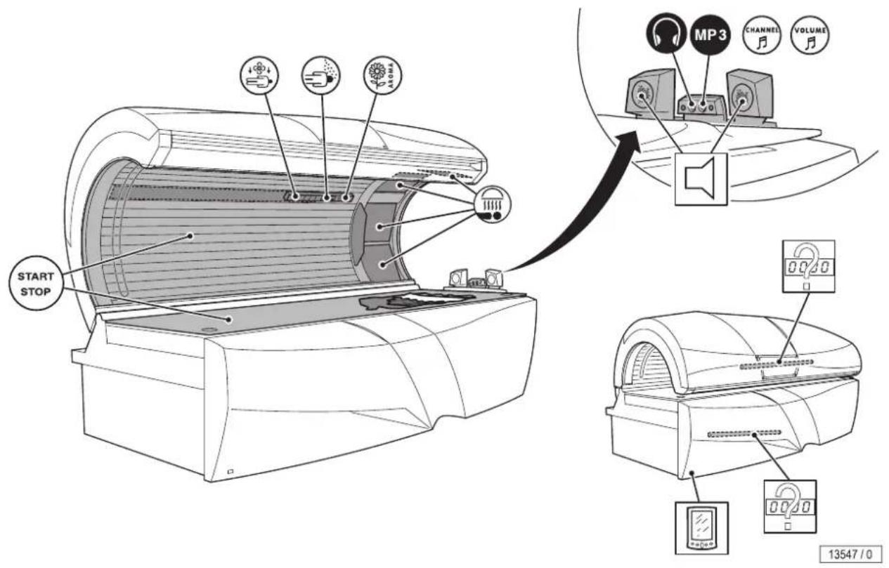
text_image
START STOP MP3 CHANNEL VOLUME 13547 / 0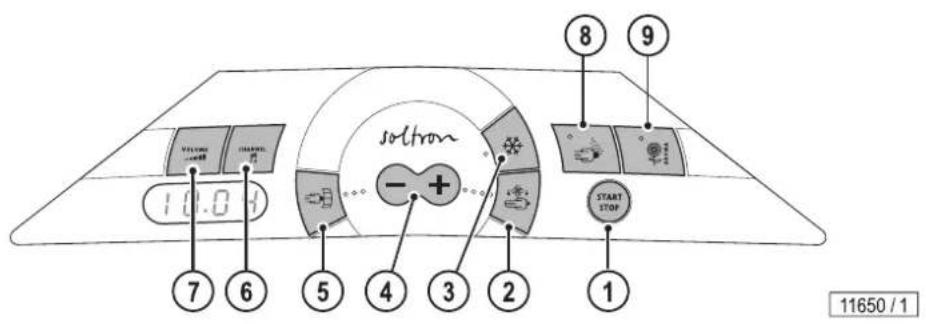
text_image
10.0 sotton - + START STOP 7 6 5 4 3 2 1 8 9 11650 / 1- START/STOP button
- Body cooling button
- Air conditioner button
- Plus/Minus button
- Facial tanner button
- Audio system button
- Volume button
- VITALIZER button
- AROMA button
4.8 Functions
| Function | Button sequence | Description | Information |
| 1. UV lamps |  | START/STOPSwitch the UV lamps on / off during tanning | If the UV lamps are switched off during tanning, the tanning time continues to run. |
| 2. Body cooling |  | Regulate body cooling,Levels 1-9 | The face cooling air nozzles can be adjusted manually. |
| 3. Air condition |  | Switching air condition off, hold the button down:OFF | |
 | Switching air condition on | ||
| 5. Facial tanner |  | Switching facial tanner off | |
 | Switching facial tanner on | 1 minute up until maximum power. | |
| 6. Audio system |  | I.CH (internal): SD card 'music' | |
 | Select title | ||
 | E-CH | E.CH (external): externally connected systems (e.g. CD-player) | |
 | Select channel | ||
 | -M3- | MP3 player | |
| 7. Volume |  | I+ | Adjusting the volume and switching-off the audio systems |
| 8. VITALIZER |  | Switching VITALIZER off | |
 | Switching VITALIZER on | ||
| 9. AROMA |  | Switching AROMA off | |
 | Switching AROMA on | ||
| Accent lighting running time | Refer to 'Voreinstellungen/Presettings',order no. 1008953-.. | ||
 | |||
| 'IR-Function' | Refer to 'Voreinstellungen/Presettings',order no. 1008953-.. | ||
 | |||
4.9 Start
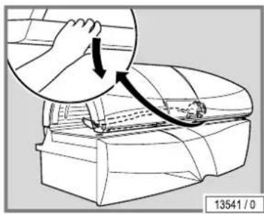
text_image
13541 / 0- Closing the canopy.
- Press the START/STOP button.
Upon starting the following functions are switched on:
- UV lamps
- Facial tanner
- Body cooling
• Air condition (optional)
• Audio system (optional)
4.10 Connect MP3 player
DANGER!

Danger of hearing damage!
Using earphones or headphones at high volume can result in permanent hearing damage.
- Do not set the volume too high.
The user can connect her/his own private MP3 player to the tanning device, if the 'Audio system' accessory is fitted.
- Mat.-No. 1001855-. provided for use by the studio operator (1.5 m / 2 x 3.5 mm stereo jack plug).
- MP3 player connection: see the documentation from the manufacturer of the MP3 player.
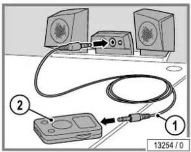
text_image
Diagram showing audio connection setup with two monitors and a device, labeled with numbered components and connection point 13254/0Connecting:
- Insert the MP3 cable (stereo jack plug) in the audio system.
- Plug the MP3 cable into the MP3 player.
- Select the music title and then start.
- Where necessary, set the volume level on the MP3 player so that the sound signal from the MP3 player is recognized by the audio system.
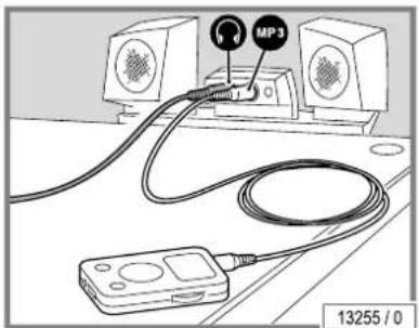
text_image
MP3 13255 / 0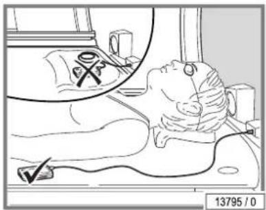
text_image
13795 / 0WARNING!
The heat might damage your MP3 player!
- Do not place the player directly in the radiation area.
The cable might crack, the connectors might be damaged.
- Do not pull on the cable when unplugging the MP3 player.
5 Cleaning and maintenance
5.1 Safety instructions when undertaking cleaning or maintenance work
DANGER!
Electricity throughout entire device!
Personnel danger due to electric shock or electric burns.
- Before beginning work disconnect all of the power connections from mains voltage.
- Secure all of the disconnected connections against accidental reactivation.
- Check that the device is disconnected from mains voltage.
- All of the work and electrical connections must comply with the national regulations of the country in which the device is being operated (e.g. the VDE regulations in Germany) and must be undertaken by appropriately trained specialists.

text_image
12427 / 0If work is to be performed on the devices, they must be deenergized. That means that all live cables must be switched off.
Switching off the device alone is insufficient, as certain points may remain energized. Therefore, switch off fuses before performing any work and – if possible – remove them.
Accidental reactivation can result in serious accidents. Immediately after deenergizing, secure all switches or fuses used for deenergizing against being switched on again.
- Lock the fuse box with a padlock.
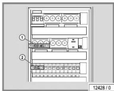
text_image
① ② 12428 / 0In case of circuit breakers which cannot be unscrewed, a strip of adhesive tape may be applied over the actuation lever with the wording 'Do not switch, danger!' (1 + 2).
A prohibition sign with the text:
'Work in progress!'
'Place: ....'
'Sign may only be removed by:......'
must always be securely mounted immediately.
5.2 Faults
Error codes are output to the display to simplify troubleshooting:
- If a fault occurs, the error code flashes on the display.
- If several errors occur, the error messages are displayed alternately.
- Error elimination is acknowledged by pressing the START/STOP button.
- If the error cannot be cleared, inform Customer Service - see page 2.
More detailed information regarding the error description and solutions is available in 'Fehlercodes/Error Codes' (order no. 1008954-..).
5.3 Cleaning
DANGER!

Infections can be spread by skin contact!
All objects/device parts, which can come into contact with the user during tanning, must be disinfected after every tanning session:
- Acrylic glass panel
- Headrest
- Handles and control panel
- Protective goggles
- MP3 cable
- Adjustable air jets

NOTE:
Adhere to the stipulated times to ensure thorough disinfection. Follow the manufacturer's instructions for use.
5.3.1 Cleaning the surfaces
Acrylic glass surfaces
WARNING!

Do not rub with a dry cloth – danger of scratching!
Failure to comply voids any warranty claims.
- For the fast, hygienic and proper cleaning of acrylic glass surfaces, use specially developed cleaning agents.
- Concentrated disinfectants or solvents (e.g. Lysoform, ethyl alcohol or other fluids containing alcohol) must never be used for cleaning.
WARNING!

Acrylic glass panels unusable due to soiling!
Soiling on the panels is burned in by the hot lamps and results in the long term in unserviceable panels.
- Remove fingerprints and other soiling carefully.
Plastic surfaces
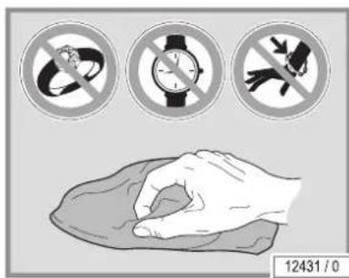
text_image
12431 / 0For cleaning the remaining painted and unpainted plastic surfaces, it is best to simply use warm water and a leather cloth. Never use aggressive cleaning agents containing alcohol or essential oils. These may lead, in the long run, to damages not covered by the guarantee.
During cleaning a slight discolouration of the leather cloth by the rubber seals must be expected for production-related reasons.
Prevent damage to the acrylic glass and plastic surfaces.
- Remove rings, watches, bracelets etc. before starting cleaning work.
5.3.2 Filter panels and lamps
- UV low pressure lamps and filter panels can be cleaned with a damp cloth and without additional cleaning agents where necessary.
- UV high pressure lamps can be cleaned with ethyl alcohol where necessary.
5.4 Cleaning plan
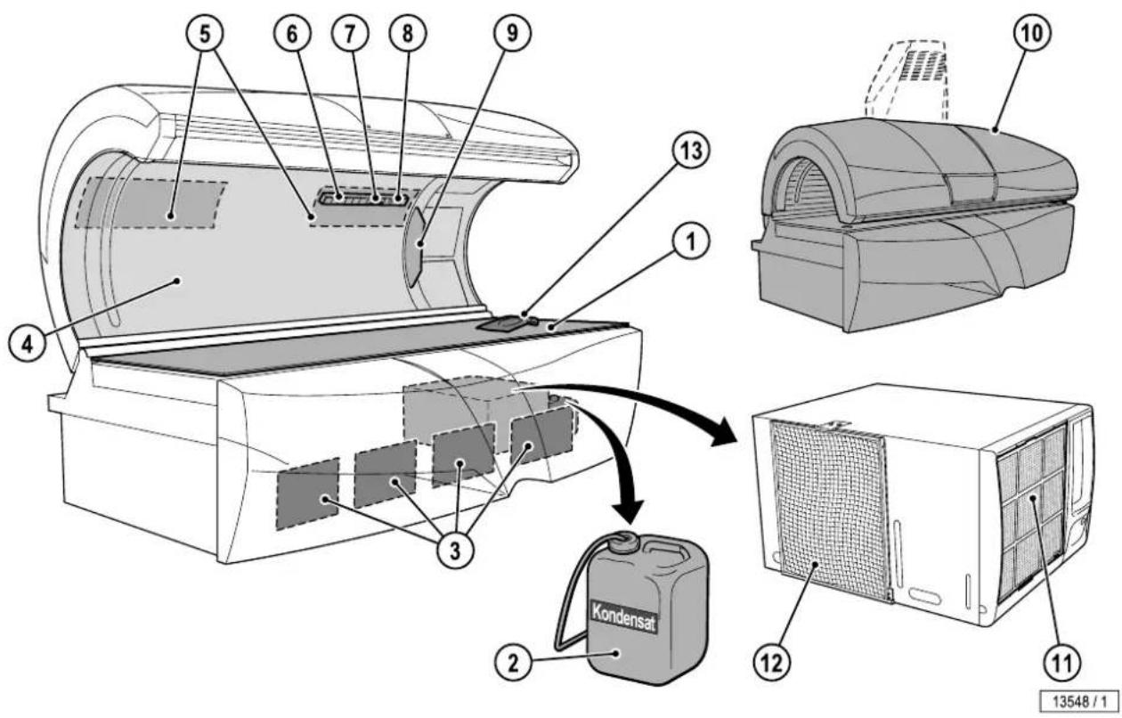
text_image
Technical diagram of a Kondensat air conditioner unit with numbered components and labeled parts| Component | Interval | Activity | See page | |||
| After each tanning session | When necessary | 50 h | ||||
| 1 | Acrylic glass panel | X | Clean and disinfect | 40 | ||
| 8 | Adjustable air nozzles | X | Clean and disinfect | 40 | ||
| 9 | Control panel | X | Clean and disinfect | 40 | ||
| 13 | Headrest | X | Clean and disinfect | 40 | ||
| Handle | X | Clean and disinfect | 40 | |||
| Protective goggles | X | Clean and disinfect | 40 | |||
| MP3 cable | X | Clean and disinfect | 40 | |||
| 2 | Condensation tank | X | Empty | 56 | ||
| 4, 10 | Surfaces | X | Clean | 40 | ||
| 5 | Air intake openings | X | Clean | 55 | ||
| 6 | Body cooling air nozzles | X | Clean | 40 | ||
| 7 | Nozzle AVS AROMA VITALIZER system | X | Clean | 40 | ||
| 3 | Filter | X | Remove and clean filter | 54 | ||
| 5 | Filter | X | Remove and clean filter | 55 | ||
| 11, 12 | Filter | X | Remove and clean filter | 56 | ||

NOTE:
Cleaning must be confirmed after each tanning session by pressing the START/STOP button (when the warm-down time for the main fan has finished).
5.5 Maintenance
Maintenance and care play a major role in deciding whether the device meets the requirements placed on it in a satisfactory manner. Compliance with the specified maintenance intervals and the careful conducting of the maintenance and care work are therefore absolutely necessary.
The current operating hours of maintenance parts can be called up in service mode (see 'Voreinstellungen/Presettings', order no. 1008953-..).
We point out that the device must be subjected to regular inspections by our customer service or an approved specialized company every 12 months (from commissioning) to maintain its proper condition!
Inspections and maintenance work that has been carried out must be entered in the equipment, operating and maintenance booklet (order no. 1010363-..).
5.5.1 Acrylic glass
WARNING!

Cosmetics may cause cracks to form on the surface!
Over the long-term cosmetics or sunscreens cause damage (e.g. crack formation on the surface).
- Ensure that cosmetics and sunscreens are removed before tanning.
The acrylic glass panels for the tanning devices are produced of acrylic glass developed especially for this application. The acrylics used feature a particularly high UV permeability and resistance, as well as an easy-care, hygienic surface that is gentle on the skin.
The acrylic glass panels are formed to device-specific shapes in a technically complex production process. Despite state-of-the-art production know-how, the presence of minor spots, air bubbles or streaks in the acrylic panels is unavoidable. In addition, hairline cracks can occur on the acrylic glass panel during operation.
These occurrences are material-related and are unavoidable in processing. However, they have no significant effect on use and are therefore not accepted as defects.
Acrylic glass panel
Over the course of time the acrylic glass panel becomes more translucent as a result of usage and must be replaced by customer-service personnel on a regular basis.
The optional partition (only for devices with air conditioning) functions as a UV filter and must be replaced by customer-service personnel on a regular basis.
5.6 Maintenance plan
WARNING!

Only use genuine spare parts of the same type! If other parts are used then the device no longer complies with the conformity declaration and may not be operated any longer! Any liability for damage or injury proven to be the result of the use of non-genuine spare parts is excluded.
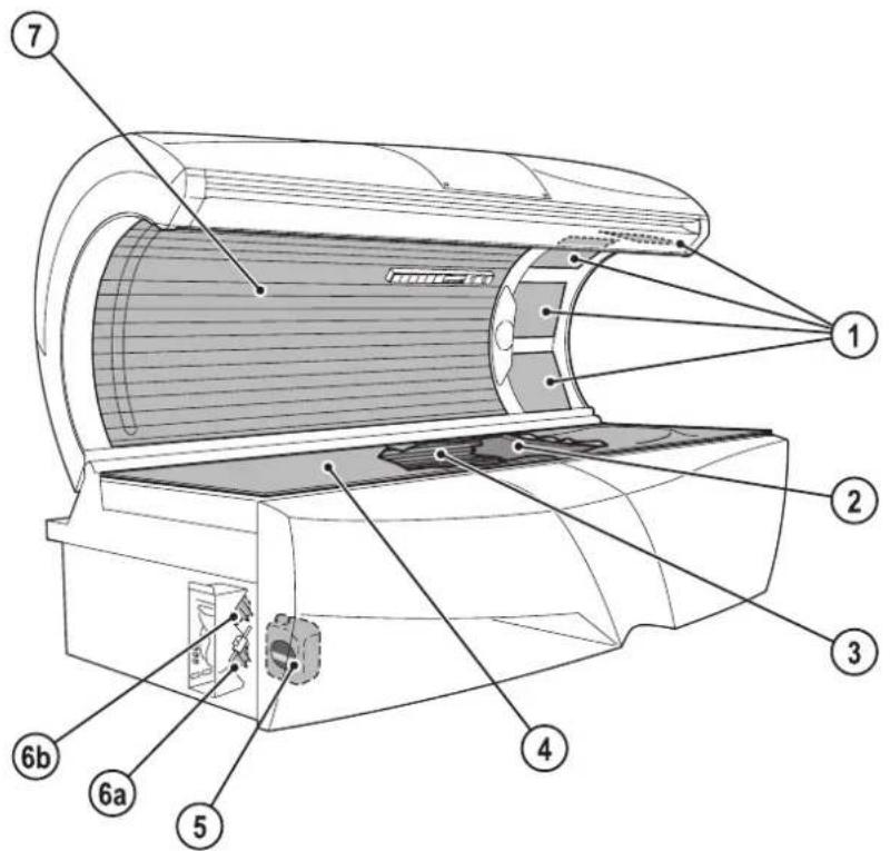
text_image
Technical diagram of an air conditioner unit with numbered parts labeled 1 through 7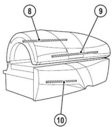
text_image
8 9 1014095/0
| Component | Interval | Activity | See page | |||||||
| When necessary | 300 h | 500 h | 1000 h | 1500 h | 3000 h | |||||
| 5 | VITALIZER | X | Replace | 58, 60 | ||||||
| 6a, 6b | AROMA canister | X | Replace | 58, 59 | ||||||
| 1 | Facial tanner UV high pressure lamps | X | Replace | 52 | ||||||
| 3 | UV low pressure lamps, base | X | Replace | 52 | ||||||
| 7 | UV low pressure lamps, canopy | X | Replace | 52 | ||||||
| 3 | Starter, base | X | Replace | 52 | ||||||
| 7 | Starter, canopy | X | Replace | 52 | ||||||
| 8 | Starter interior lighting | X | Replace | 53 | ||||||
| 10 | Starter accent lighting, front panel | X | Replace | 54 | ||||||
| 4 | Acrylic glass panel | X | Replace | 43 | ||||||
| 1 | Facial tanner filter panels | X | Replace | 52 | ||||||
| 2 | Partition | X | Replace | 43 | ||||||
| 9 | Starter accent lighting, canopy | * | ||||||||
* Contact the customer service if the accent lighting in the canopy fails.
5.7 Cleaning and maintenance work preparation
5.7.1 Lift up the acrylic glass panel and remove the partition
- Remove the screws.
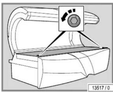
natural_image
Technical line drawing of a mechanical component with a control panel and mounting bracket (no text or symbols)
text_image
1 2 2 13521 / 0- Lift up the acrylic glass panel.
- Lift up the supports and prop the acrylic glass panel on them.
WARNING!

Risk of scratching!
Use the recesses provided on the acrylic glass panel.
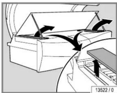
natural_image
Diagram of a mechanical device with directional arrows indicating motion or flow, no readable text or symbols present.- Remove the lamp covers at the head and foot ends.
text_image
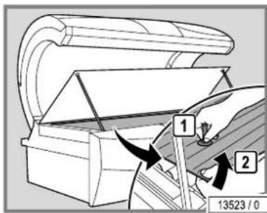
1 2 13523 / 0- Raise the partition with the suction cup (only for devices with air conditioning).
natural_image
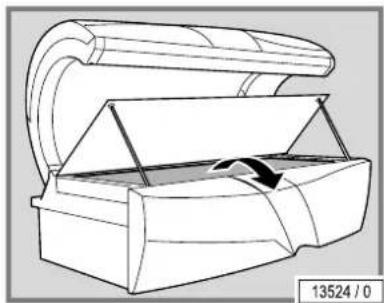
Technical line drawing of a mechanical device with an arrow indicating motion or force (no text or symbols)- Remove the partition.
text_image
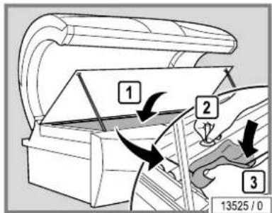
1 2 3 13525 / 0The assembly is the same process in reverse order.
When assembling please note:
- Clean the partition.
– Hold the partition with a cloth in order to prevent finger prints.
text_image
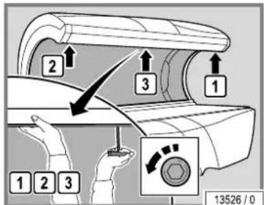
13526 / 05.7.2 Remove the canopy panel
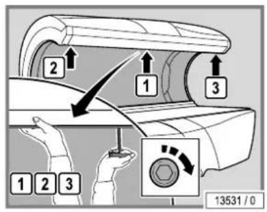
- Undo the screws. Remove the outside screws first and then remove the screws in the middle.
– Support the canopy panel with one hand so that it does not fall down.
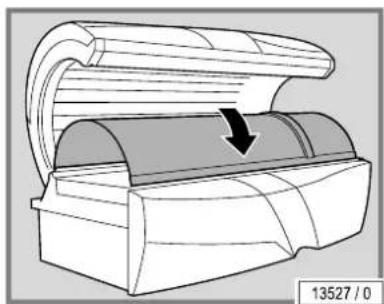
natural_image
Diagram of a mechanical device with a curved top and internal structure, showing a downward arrow indicating motion (no text or symbols present)- Carefully lay the canopy panel aside.
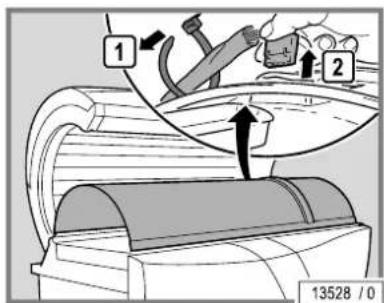
text_image
1 2 13528 /0The canopy panel must be completely removed from the device in order to replace the lower, long, low pressure UV lamps.
- Undo the cable ties and unplug the connectors.
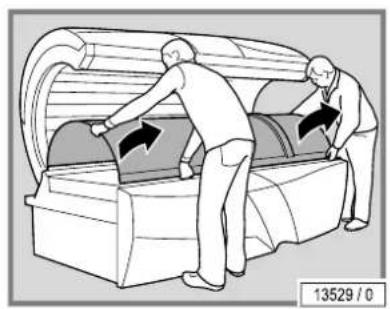
natural_image
Illustration of two workers installing or adjusting a large cylindrical device (no text or symbols visible)- Remove the canopy panel with the aid of a helper.
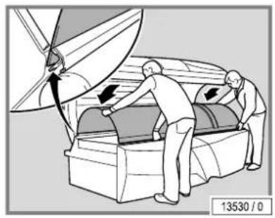
natural_image
Illustration of two people handling a large object with directional arrows, no text or symbols presentThe assembly is the same process in reverse order.
When assembling please note:
- Carefully lay the canopy panel in the guide.
text_image
2 1 3 1 2 3 13531 / 0– Support the canopy panel with one hand so that it does not fall down.
- Refit and retighten the scres Refit the middle screws first and then the outer screws.
- Remove fingerprints and other soiling carefully.
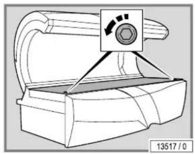
5.7.3 Open the bed base
- Remove the screws.
natural_image
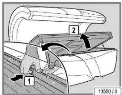
Technical line drawing of a mechanical component with no visible text or symbols- Raise the acrylic glass panel and grasp the recessed grip.
- Lift up the bed base.
text_image
1 2 13550 / 0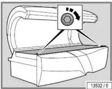
natural_image
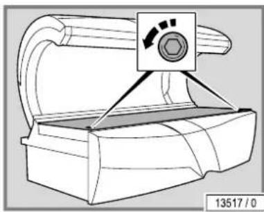
Technical line drawing of a mechanical component with a hexagonal button and triangular base (no text or symbols)The assembly is the same process in reverse order.
5.8 Instructions for replacing the lamps
The UV effect of the lamps and thus the tanning effect decreases over the course of time. Therefore, the replacement intervals specified in the maintenance plan must be adhered to.
UV filters are utilized in order to control the UV radiation, e.g. the filter panels on the facial tanner. However, the filter effect decreases over the course of time. Therefore, the replacement intervals specified in the maintenance plan must be adhered to.
5.8.1 Low pressure lamps
- Replace faulty UV low pressure lamps immediately.
• Always replace the entire set of lamps after the specified operating time. - Turn 90^ and carefully remove from the socket.
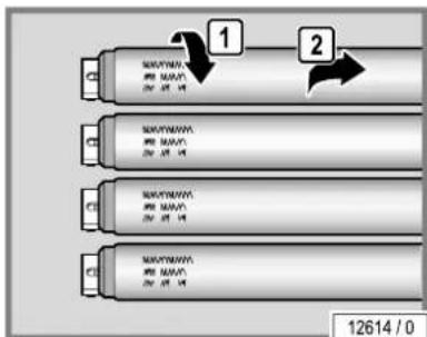
text_image
1 2 12614 / 0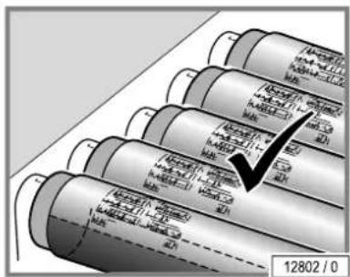
text_image
12802 / 0UV low pressure lamps possess a reflector which directs the light outwards. The lamps must be mounted in such a way that the rear side of the reflector is located on the device side.
text_image
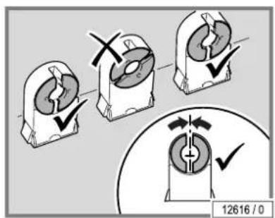
12616 / 0- Push the pins vertically into the socket from above.
text_image
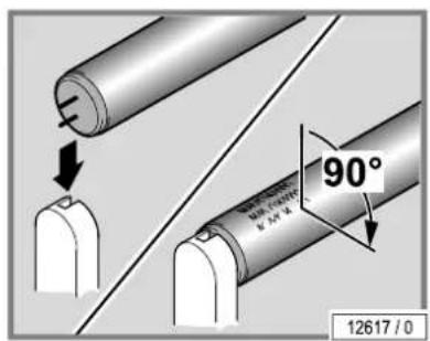
90° 12617 / 0- Turn the lamp 90°. The lettering must be oriented towards the outside (i.e. towards the tanning room or towards the user).
5.8.2 Makrolon tubes
Coloured makrolon tubes can be fitted on the accent lamps. The makrolon tubes do not have to be changed, merely refitted with the new lamps.
- Remove the makrolon tube from the old lamp.
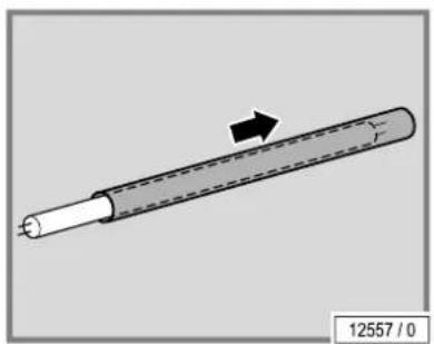
natural_image
Diagram of a cylindrical object with a black arrow indicating direction, labeled '12557 / 0' at bottom (no other text or symbols)- Slide the makrolon tube onto the new lamp.
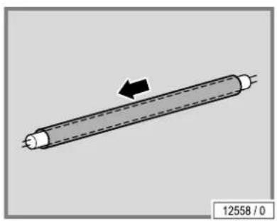
natural_image
Diagram of a cylindrical object with an arrow indicating direction, labeled '12558 / 0' (no text or symbols on the object itself)
natural_image
3D diagram of a cylindrical mechanical component with directional arrows indicating rotation (no text or symbols)5.8.3 Starter
- Replace faulty starters immediately.
You can recognize a faulty starter by the blackened ends of the (UV) low pressure lamps or when the (UV) low pressure lamps can no longer be started.
Operating a (UV) low pressure lamp with a faulty starter significantly shortens its service life. The (UV) low pressure lamp loses power and may begin to flicker under certain circumstances.
The starters are located in either one of the two lamp sockets or become visible when the (UV) low pressure lamps are removed.
- Turn 90° and carefully remove from the socket.
5.8.4 High pressure lamps and filter panels
UV high pressure lamps are used in facial tanners.
DANGER!

Fire hazard due to overheated lamps!
Non-approved high pressure lamps can explode. Hot lamp components can set other parts on fire. People can be killed or severely injured due to smoke inhalation and fire.
- Only fit the high pressure lamps specified by the manufacturer.
- Clean the inside of the device regularly. Dust particles are flammable!
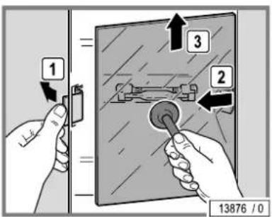
text_image
1 2 3 13876 / 0- Release the clamping holder.
- Lift the filter panel, pull it out of the guide and remove it.
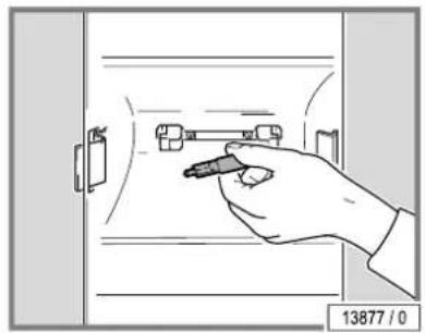
natural_image
Hand holding a tool interacting with a door handle (no text or symbols visible)- Unplug the UV lamps.
- Clean the reflector.
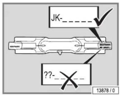
text_image
JK-_ 13878 / 0 ??-_X- Only utilize original UV lamps.
- Only touch new lamps with a cloth.

text_image
13879 / 0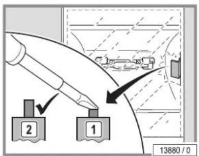
text_image
13880 / 0– Test the safety switch to ensure that it works.
The safety switch ensures that the device switches off in the event of a faulty filter panel or when a filter panel is missing.
- Press the button.
If the button springs back automatically then it is functional.
- Replace the filter panel.
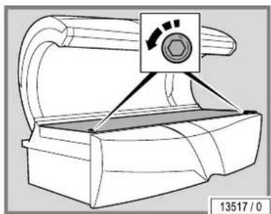
natural_image
Technical line drawing of a mechanical component with a hexagonal nut and directional arrow (no text or symbols)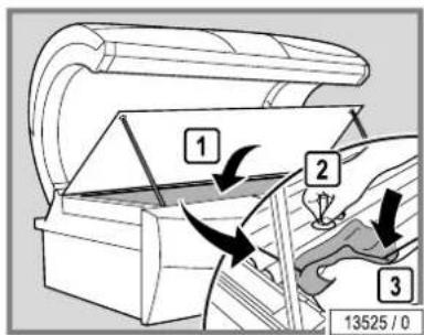
text_image
1 2 3 13525 / 0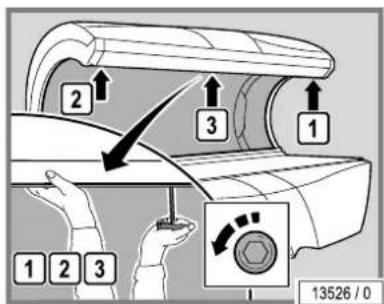
text_image
13526 / 0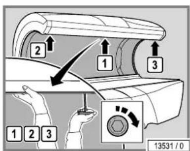
text_image
13531 / 05.9 Cleaning or replacing UV lamps in the base
- Lift up the acrylic glass panel and then remove the lamp covers and the partition: see page 45.
Replacing the lamps: see page 48.
Replacing the starter: see page 50.
The assembly is the same process in reverse order.
When assembling please note:
- Clean the partition.
– Hold the partition with a cloth in order to prevent finger prints.
5.10 Cleaning or replacing UV lamps and filter panels in the canopy
- Removing the canopy panel: see page 46.
The following components listed in the maintenance plan are fitted in the canopy:
• 1.80 m UV low pressure lamps
• Facial tanner UV high pressure lamps
- Facial tanner filter panels
Replacing the lamps: see page 48.
Replacing the starter: see page 50.
UV high pressure lamps and filter panels: see page 50.
The assembly is the same process in reverse order.
When assembling the device please note:
– Support the canopy panel with one hand so that it does not fall down.
- Refit and retighten the screws. Refit the middle screws first and then the outer screws.
5.11 Cleaning or replacing the interior lights
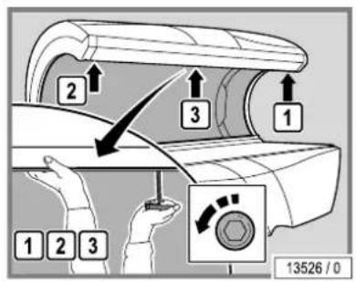
text_image
13526 / 0- Removing the canopy panel: see page 46.
flowchart
graph TD
    1 --> 2
    2 --> 3
    3 --> 4
    4 --> 5
    5 --> 6
    6 --> 7
    7 --> 8
    8 --> 13270 / 0
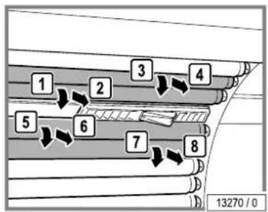
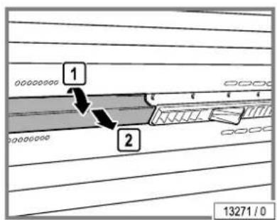
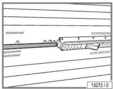
- Remove the 2 lamps above and the 2 lamps below the interior lights.
text_image
1 2 13271 / 0- Remove the cover.
natural_image
Technical line drawing of a mechanical component with no visible text or symbolsReplacing the lamps: see page 48.
Replacing the starter: see page 50.
The assembly is the same process in reverse order.
text_image
1 1 2 13533 / 05.12 Cleaning or replacing the front panel accent lighting
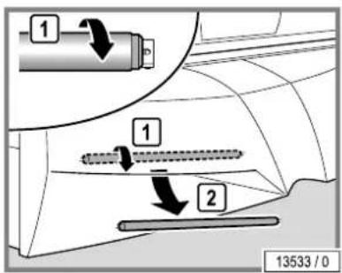
- From the front reach under the front panel and remove the effect lamps.
Replacing the lamps: see page 48.
Replace the starter: see page 50.
Makrolon tubes (if fitted): see page 49.
The assembly is the same process in reverse order.
5.13 Cleaning the filter in the base
natural_image
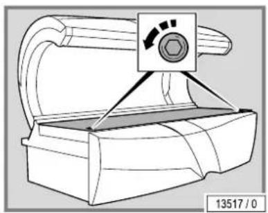
Technical line drawing of a mechanical component with no visible text or symbols- Opening the bed base: see page 47.
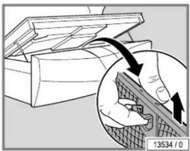
natural_image
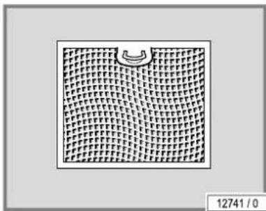
Diagram showing a hand using a tool to cut a brick wall, with an inset magnified view highlighting the process (no text or symbols present)- Remove the filter.
natural_image
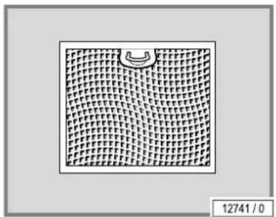
Grid pattern with a curved arrow on the top-right corner, no text or symbols present- Cleaning the filter when moist or dry.
Dry cleaning: Vacuum cleaner (depending on the degree of soiling) Moist cleaning: Use water and detergent or put in a dish-washer
natural_image
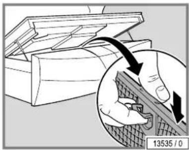
Diagram showing a hand using a tool to cut or repair a component, with an inset magnified view highlighting the process (no text or symbols present)WARNING!

The device may be damaged by moisture!
The cleaned filters must be dry before they are replaced.
- Refit the cleaned and dried filters.
- Close the bed base.
5.14 Cleaning the air intake openings
natural_image
Diagram of a mechanical component with curved arrows indicating motion or movement, no readable text or symbols present.DANGER!

Fire hazard due to dust particles in the air intake openings!
Dust particles are flammable! Regularly remove dust particles from the air intake area.
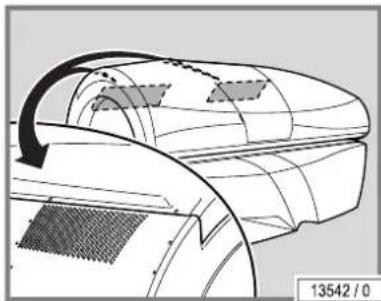
- Use a vacuum cleaner to prevent dust particles from getting inside the unit.
- If necessary, cover the canopy in order to prevent the paint from being scratched.
– Vacuum the air intake openings.
5.15 Cleaning the canopy filter mats
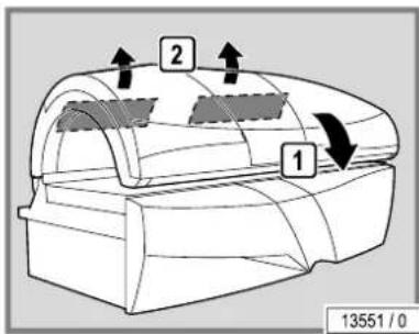
text_image
1 2 1 13551 / 0- If necessary, cover the canopy in order to prevent the paint from being scratched.
– Remove the filter mats fitted at the back of the canopy.
– Dry or moist clean the filter mats or replace with new ones.
Dry cleaning: Vacuum cleaner (depending on the degree of soiling) Moist cleaning: Water and detergent
- Do not clean in the dish-washer!
natural_image
Simple 3D rectangular block with no text or symbols on its surface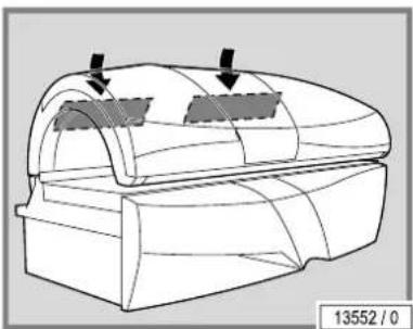
natural_image
Technical line drawing of a mechanical component with two arrows indicating features (no text or symbols)WARNING!

The device may be damaged by moisture!
The cleaned filters must be dry before they are replaced.
- Refit the cleaned and dried filter mats.
5.16 Air conditioning: Empty the condensation tank and clean the filter
WARNING!

Damage to the device through soiled filters and cooling fins!
Regularly check the filter grill and cooling fins on the air conditioning system and clean if necessary.
We recommend using the specially manufactured fin comb, art-no. 15720470, to clean the cooling fins.
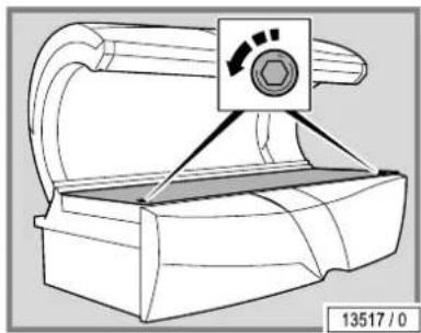
natural_image
Technical line drawing of a mechanical device with no visible text or symbols- Opening the bed base: see page 47.
text_image
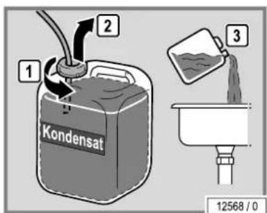
1 2 Kondensat 3 12568 / 0- Bring the condensation tank forwards.
- Disconnect the hose on the condensation tank.
- Empty the condensation tank.
text_image
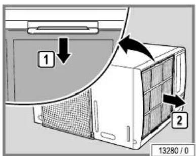
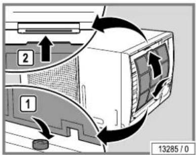
1 2 13280 / 0- Remove the filter from the holder.
natural_image
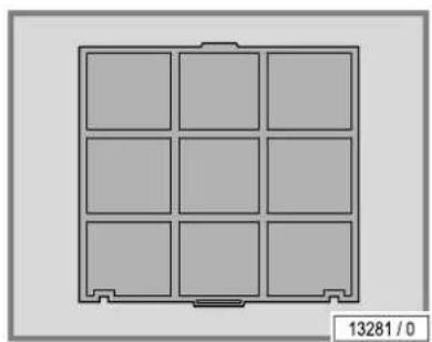
Diagram of a 3x3 grid layout with no text or symbols, showing a central rectangular block and corner compartments (no readable labels or symbols)- Cleaning the filter when moist or dry.
Dry cleaning: Vacuum cleaner (depending on the degree of soiling) Moist cleaning: Water and detergent
- Do not clean in the dish-washer!
natural_image
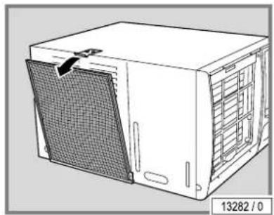
Line drawing of a white industrial machine with a mesh cover and ventilation slots (no text or symbols)- Remove the filter from the holder.
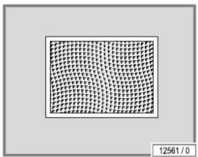
natural_image
Grid pattern with no text or symbols, showing a uniform grid of small squares (no readable text or symbols)- Cleaning the filter when moist or dry.
Dry cleaning: Vacuum cleaner (depending on the degree of soiling) Moist cleaning: Use water and detergent or put in a dish-washer
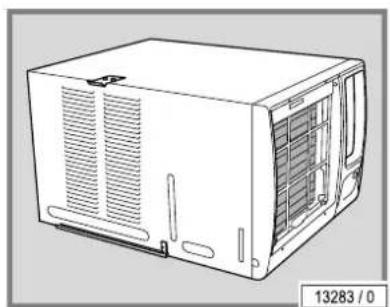
natural_image
Line drawing of a white industrial air conditioner unit with ventilation grilles and ventilation ducts (no text or symbols)- Use a fin comb to clean the air conditioning's dirty cooling fins.
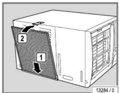
text_image
1 2 13284 / 0WARNING!

The device may be damaged by moisture! The cleaned filters must be dry before they are replaced.
- Refit the cleaned and dried filters.
- Ensure that the filter is correctly positioned in the holder.
text_image
1 2 1 13285 / 0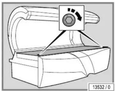
natural_image
Technical line drawing of a mechanical component with no visible text or symbols- Connect the condensation tank to the hose.
- Refit the condensation tank.
- Close the bed base.
5.17 AVS AROMA VITALIZER system maintenance
The VITALIZER function sprays a fine mist of AQUA SOLAR WITH SKIN+ ADDITIVE into the interior of the device for body cooling (see 'AQUA SYSTEM PRODUCT INFORMATION', order no. 1011201-..).


DANGER!
Customer health hazard!
Water that has been contaminated with bacteria can cause skin rashes and other allergic reactions in device users.
- Therefore you must never fill the VITALIZER canister with tap water or other liquids.
- Only replace the VITALIZER canister with a genuine canister.
- Do not add any liquid that remains in the old canister to the new canister!
- Ensure that the maximum temperature specified is not exceeded during transport and storage.
- Note the expiry date on the canister.
This AVS AROMA VITALIZER system also includes the 'ENERGY' fragrance, which is distributed through the head nozzles. Another fragrance called 'CABIN' is distributed within the cubicle.
Other fragrances are also available. Contact JK-International GmbH, Division JK-Licht for further details (see page 2).
5.17.1 Changing the AROMA canister
- Opening the bed base: see page 47.
natural_image
Technical line drawing of a mechanical component with a control knob and directional arrow (no text or symbols)- Remove the AROMA canister.
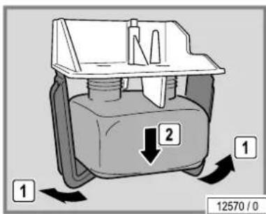
text_image
1 2 1 12570 / 0- Unscrew the lid on the new canister.
- Write the date on the canister.
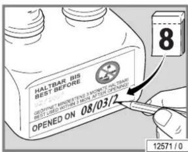
text_image
HALTBAR BIS BEST BEFORE GEDPINE MINDERTENG 3 MONATE HALTBAR BEST USED WITHIN 3 MON. AFTER OPENING OPENED ON 08/03/2 12571 / 0- Fit the canister in the holder.
- Close the bed base.
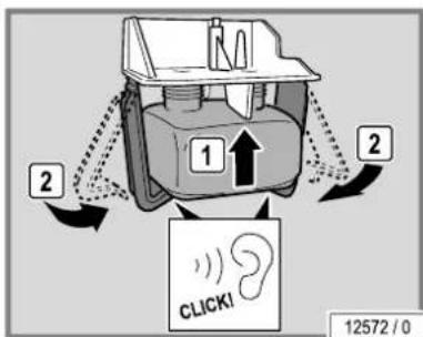
text_image
1 2 1 2 CLICK! 12572 / 0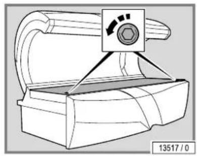
natural_image
Technical line drawing of a mechanical component with a control knob and mounting bracket (no text or symbols)5.17.2 Replacing the VITALIZER canister
- Opening the bed base: see page 47.
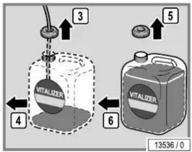
text_image
VITALIZER 4 3 5 VITALIZER 6 13536 / 0- Remove the canister.
- Unscrew the lid on the new canister.
- Remove the lid with the hose from the old canister.
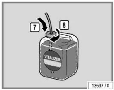
text_image
7 8 VITALIZER 13537 / 0- Screw the lid with the hose onto the new canister.
– Push the hose well down so that it touches the bottom of the canister. - Put the canister back in the device.
- Close the bed base.
Venting
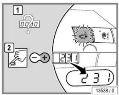
text_image
1 00/0 2 - + 231 231 13538 / 0
NOTE:
Ventilate after changing the canister by switching over to preset mode and then select Function 231 (see 'Voreinstellungen/Presettings', order no. 1008953-..).

flowchart
graph TD
    A["Start STOP"] --> B{START STOP}
    B --> C["End"]
    style A fill:#f9f,stroke:#333
    style B fill:#ccf,stroke:#333
    style C fill:#dfd,stroke:#333
- Press the AROMA button.
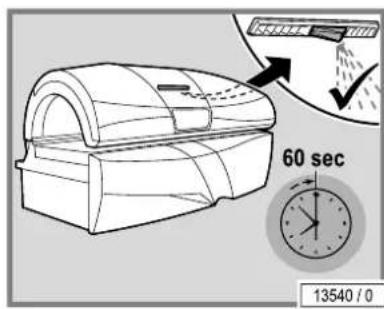
text_image
60 sec 13540 / 0- Close the canopy.
The system will now be ventilated for 1 minute. VITALIZER will be released from the nozzles during this period.
- Test the VITALIZER function afterwards. Repeat the ventilation process if it does not work.
6 Technical data
6.1 Power, connection rating and noise level
The Safety Checked seal (GS seal) certifies that the tanning device fulfils the requirements of the Equipment and Product Safety Act (GPSG). The test mark is located on the type plate.
S-50 SUPER POWER
| Power consumption rating with air conditioning: | - | |
| Power consumption rating without air conditioning: | 6900 W | |
| Rated frequency: 50 Hz | ||
| Rated voltage: 400-415 V 3N~ 230-240 V ~3 | ||
| Rated fuses: 3 x 16 A (time delay) 3 x 35 A (time delay) | or | |
| Connecting line: H05VV-F 5G 4 mm ^2 | H05VV-F 5G 6 mm ^2 | |
| Noise level 1m away from device: | 66.4 dB(A) | |
| Noise level inside the device: | <81 dB(A) | |
| Load on the acrylic glass panel: | max. 135 kg | |
| Weight: | approx. 360 kg | |
S-50 TWIN POWER
| Power consumption rating with air conditioning: | - | |
| Power consumption rating without air conditioning: | 8900 W | |
| Rated frequency: 50 Hz | ||
| Rated voltage: 400-415 V 3N~ 230-240 V ~3 | ||
| Rated fuses: 3 x 20 A (time delay) 3 x 35 A (time delay) | or | |
| Connecting line: H05VV-F 5G 4 mm ^2 | H05VV-F 5G 6 mm ^2 | |
| Noise level 1m away from device: | 66.4 dB(A) | |
| Noise level inside the device: | <81 dB(A) | |
| Load on the acrylic glass panel: | max. 135 kg | |
| Weight: | approx. 370 kg | |
S-50 TURBO POWER
| Power consumption rating with air conditioning: | 10200 W | |
| Power consumption rating without air conditioning: | 9500 W | |
| Rated frequency: 50 Hz | ||
| Rated voltage: 400-415 V 3N~ 230-240 V ~3 | ||
| Rated fuses: 3 x 20 A (time delay) 3 x 35 A (time delay) | or | |
| Connecting line: H05VV-F 5G 4 mm2 | H05VV-F 5G 6 mm2 | |
| Noise level 1m away from device: | 66.4 dB(A) | |
| Noise level inside the device: | <81 dB(A) | |
| Load on the acrylic glass panel: | max. 135 kg | |
| Weight: | approx. 380 kg | |
S-55 SUPER POWER
| Power consumption rating with air conditioning: | - | |
| Power consumption rating without air conditioning: | 7900 W | |
| Rated frequency: 50 Hz | ||
| Rated voltage: 400-415 V 3N~ 230-240 V ~3 | ||
| Rated fuses: 3 x 20 A (time delay) 3 x 35 A (time delay) | or | |
| Connecting line: H05VV-F 5G 4 mm2 | H05VV-F 5G 6 mm2 | |
| Noise level 1m away from device: | 66.4 dB(A) | |
| Noise level inside the device: | <81 dB(A) | |
| Load on the acrylic glass panel: | max. 135 kg | |
| Weight: | approx. 375 kg | |
S-55 TWIN POWER
| Power consumption rating with air conditioning: | - | |
| Power consumption rating without air conditioning: | 9900 W | |
| Rated frequency: | 50 Hz | |
| Rated voltage: 400-415 V 3N~ 230-240 V ~3 | ||
| Rated fuses: 3 x 25 A (time delay) | 3 x 50 A (time delay) or | |
| Connecting line: H05VV-F 5G 4 mm2 | H05VV-F 4G 10 mm2 | |
| Noise level 1m away from device: | 66.4 dB(A) | |
| Noise level inside the device: | <81 dB(A) | |
| Load on the acrylic glass panel: | max. 135 kg | |
| Weight: | approx. 385 kg | |
| S-55 TURBO POWER | ||
| Power consumption rating with air conditioning: | 11400 W | |
| Power consumption rating without air conditioning: | 10700 W | |
| Rated frequency: 50 Hz | ||
| Rated voltage: 400-415 V 3N~ 230-240 V ~3 | ||
| Rated fuses: 3 x 25 A (time delay) 3 x 50 A (time delay) | or | |
| Connecting line: H05VV-F 5G 4 mm2 | H05VV-F 4G 10 mm2 | |
| Noise level 1m away from device: 66.4 dB(A) | ||
| Noise level inside the device: | <81 dB(A) | |
| Load on the acrylic glass panel: | max. 135 kg | |
| Weight: | approx. 395 kg | |
6.2 Dimensions
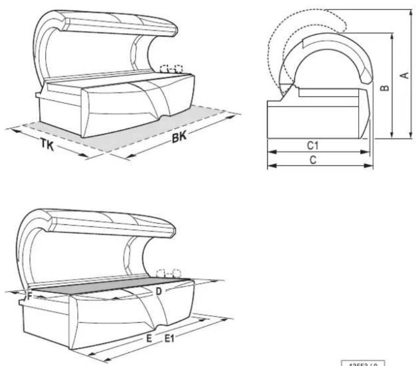
13553/0
A = 1700 mm
B = 1315 mm
C = 1443 mm
C1 = 1425 mm
D = 2250 mm
E = 2270 mm
E1 = 2370 mm
F = 830 ~mm
TK = 2100 mm
BK = 2400 mm
6.3 Lamp sets
WARNING!

The conformity declaration and the GS test mark only apply for the specified UV lamps and filer panels. The use of other UV lamps and filter panels voids the operating licence.
Moreover, the UV lamps must be marked with a matching equivalence key, see attachment page 78.
The UV lamps used are broadband radiators that can be operated with different wattages (approx. 240-520 W).
6.3.7 Accent lighting

text_image
d e f 10335 / 0Design Peach Party / Design Queen Berry
| Number | Description | Power | Order no. | |
| d) | 1 | Low pressure lamp blue | 36 W | 11792-.. |
| 1 | Starter S10 (5-65 W) | 10047-.. | ||
| e) | 1 | Low pressure lamp white | 58 W | 1002108-.. |
| 1 | Makrolon tube pink | 1002101-.. | ||
| 1 | Starter S10 (5-65 W) | 10047-.. | ||
| f) | 1 | Low pressure lamp white | 36 W | 1002106-.. |
| 1 | Makrolon tube magenta | 1002107-.. | ||
| 1 | Starter S10 (5-65 W) | 10047-.. |
6.4 Spare parts and accessories
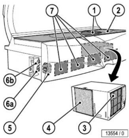
text_image
1 2 7 6b 6a 5 4 3 13554 / 0Number Description Order no.
| 1 1 Partition 1501870-.. | ||
| 2 1 Acrylic glass panel 1004424-.. | ||
| 3 1 Filter - | ||
| 4 1 Filter 51937-.. | ||
| 5 1 VITALIZER, 6000 ml 804150-.. | ||
| 6 1 AROMA, 100 ml | ||
| a) CABIN 701358-.. | ||
| b) ENERGY 100000669 | ||
| 7 4 Filter 52104-.. | ||
| 1 Protective goggles 84592-.. | ||
| 1 Headrest 78347-.. | ||
| 1 MP3 cable 1001855-.. | ||
| 1 Allen-key 83828-.. |
7 Appendix
7.1 JK timer controls
The following coin modules/time control systems can be utilized with the S-50 / S-55 series devices.
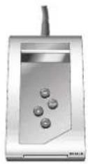
MCS III plus
Order no.: 500000458
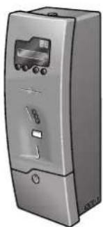
natural_image
Illustration of a silver industrial air conditioner unit with control panel and display (no text or symbols visible)MCS IV plus
Order no.: 34010400
natural_image
Illustration of a silver industrial machine with control panel and buttons (no visible text or symbols)MCS VI plus
Order no.: 34009700
natural_image
Illustration of a silver industrial machine with control panel and display (no text or symbols visible)Studiopilot
Order no.: 34009900
7.2 Signs and stickers on the device
Danger area warning signs are attached to the device. The signs shown below are examples. Ensure that the warning signs are always clearly recognisable and legible. Any missing warning signs or stickers must be replaced.
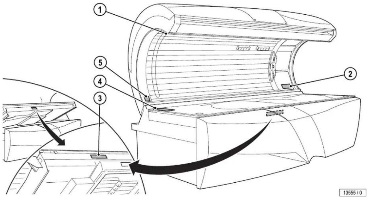
text_image
Technical diagram of a car air conditioner unit with numbered components and airflow direction arrows1: Name plate
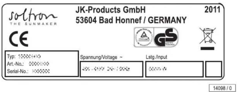
text_image
soltron THE SUNMAKER JK-Products GmbH 53604 Bad Honnef / GERMANY 2011 CE Typ: 10000+10 Art.-No.: 5000000 Serial-No.: 5000000 Spannung/Voltage ~ 400.495V DN/100Hz Lstg./Input 5000V 14098 / 0The name plate is attached to the interior side of the canopy. It contains important information for identifying the device (e.g. the serial number = Serial-No.).
2: EU warning sticker (1504234-..)


WARNUNG:
Ultraviolet radiation may cause injury to eyes and skin. Such as skin aging and eventually skin cancer. Read operating instructions/ JK protection advice carefully. WEAR THE PROTECTIVE GOOGLES PROVIDED. Certain medicines and cosmetics may increase sensitivity. On no account use the surbed if the filter glasses are broken.

natural_image
Blank gray rectangle with no visible text, symbols, or featuresXXXXXX-03-
11982/1
This sticker also includes the language form 1504231-.. (see Technical Documentation folder).
3: USA/Canada export sticker (84829-..)
HINWEIS
We emphasize that these devices must not be exported to or operated in the USA or Canada! The manufacturer does not accept any liability in case of non-observance of this notice!
REMARQUE
The sticker is located behind the front panel.
4: Lamp set sticker
| Engolone ESPRY 770-8 DYNAMIC POWER | |||||||
| ①②③④ | ① | 16x | Engolone TRESO 80-200 W 65 | 1504298- | |||
| ② | 8x | Engolone TRESO 80-200 W 65 | 1504298- | ||||
| ③ | 22x | Engolone TRESO 80-200 W 65 | 1504298- | ||||
| ④ | 3x | 4x | 2x 2x | Engolone ULTRA 927W ULTRA PERFORMANCE 952 ULTRA PERFORMANCE 952 Engolone TRESO 8 W 65 | 12745 107740- 1074264- 1503763- | ||
| ⑤ | - | - | - | Engolone TRESO 80-200 W 65 | - | ||
| EN SH.000000, SMA.500.2.1969 | ⑥ | 3x | 2x 2x | Engolone ULTRA 295 W ULTRA PERFORMANCE 592 GLADYLABNVERMEL | 1578364- 1530015- 1509778- | ||
| JK-Products GmbH / GERMANY 10/3/16-6-01 | |||||||
12846/0
The precise details of the required lamps are available in the separate appendix.
5: Maintenance instruction sticker (800701-..)
ACHTUNG!
This sunbed must be checked and serviced at regular intervals in accordance with the manufacturer's specifications. In order to rule out entirely any risk of physical injury. Label wording = "Date of manufacture ... quarter/year"
Example for calculating the equivalence key range (1), see the lamp configuration sticker:
If the equivalence key of the lamp with which the device has been equipped during the type approval is
100-R-47/3.2,
the equivalence key range with which the device should be marked is calculated as follows:
Bottom value of the X section: 0.75 x 47 = 35.25
Bottom value of the Y section: 0.85 × 3.2 = 2.72
Top value of the Y section: 1.15 × 3.2 = 3.68
X is rounded up to the next whole value, Y will be rounded to the first decimal place after the point. The equivalence key range for fluorescent lamps is then:
100-R-(35-47)/(2.7-3.7)
| 1 2 3 4 5 6 | Ergodine ESPRAT 770-S DYNAMIC POWER | |||||
| ① | 16x | Ergodine TREND 80-200 W ES | 1504250- | 100-R- (35-47)/(2,7-3,7) | ||
| ② | 2x | Ergodine TREND 80-200 W ES | 1504250- | 100-R- (35-47)/(2,7-3,7) | ||
| ③ | 22x | Ergodine TREND 80-200 W ES | 1504250- | 100-R- (35-47)/(2,7-3,7) | ||
| ④ | 2x | 4x | Ergodine ULTRA 85W ULTRA PERFORMANCE 862 ULTRA PERFORMANCE 862 Ergodine 1982XU 6 W ES | 12045 1007643- 1006294- 1503683- | ||
| ⑤ | - | - | Ergodine TREND 80-200 W ES | - | 100-R- (35-47)/(2,7-3,7) | |
| EN EN: 199256.6.2T, max. Euro: 378897 | ⑥ | 2x | Ergodine ULTRA 250 W ULTRA PERFORMANCE 382 OLAS/CLASS/VERPIEL... | 1508364- 1500035- 1389750- | ||
| JK-Products GmbH / GERMANY 1QH3666-01 | ||||||
7.3.1 Description of the equivalence keys for UV fluorescent lamps
The equivalence key for UV fluorescent lamps for tanning that is represented in detail in the IEC 61228 and that is marked on the lamp in a readable and permanent manner, is described in the following.
The equivalence key has the following structure:
Wattage – Reflector type key – UV key.
The following reflector type key should be used for the equivalence key: O with lamps without reflector;
B with lamps that have a wide reflecting angle > 230^ ;
N with lamps that have a narrow reflecting angle < 200^ ;
R with lamps that have the usual reflecting angle 200^ ≤ ≤ 230^ .
The following UV key should be used for the equivalence key:
$$ \mathrm{UVkey} = \mathrm{X} / \mathrm{Y}; $$
X = the entire effective erythematic UV radiation strength across the range 250 nm to 400 nm;
Y = the relationship of the non-melanoma skin cancer effective UV radiation strength ≤ 320 nm and > 320 nm.
X is specified in mW/m ^2 and rounded up to the next whole value, Y will be rounded to the first decimal place after the point. The effective values apply for a distance of 25 cm and under the conditions of an optimum UV radiation strength.
Note
One example for an equivalence key is specified below:
- 100 W reflector lamp with a reflector angle of 220^
• erythematic UV radiation strength (250 nm to 400 nm) = 47 mW/m² - short wave NMSC effective UV radiation strength ( ≤ 320 nm) = 61 mW/m ^2
- long wave NMSC effective UV radiation strength (> 320 nm) = 19 mW/m²
- lamp equivalence key: 100–R–47/3.2
8 Index
A
Accent lighting 72
Accessories.... 18, 73
Acrylic glass (care)...... 40
Acrylic glass panel Permitted load 62
Acrylic glass panel - sunbed..... 43
Acrylic glass panels (product information) 43
Adolescents.... 8, 19
Allergies 21
Assembly....9
AVS AROMA VITALIZER system maintenance .... 58
C
Care 40
Changing the AROMA canister.... 59
Changing the starter.... 50
Children.... 20
Cleaning.... 39, 40 Air conditioning.... 56
Air conditioning filter ..... 56
Filter.... 54
Filter mats.... 55
Lamps, filter panels ...... 41
Cleaning / replacing the UV lamps Base 52
Cleaning or replacing the accent lighting Front panel .... 54
Cleaning or replacing the interior lights.... 53
Cleaning overview...... 41
Cleaning the air intake openings.... 55
Cleaning the filter 54, 55
Commissioning.... 11
Connect MP3 player.... 37
Contact lenses 21
Copy protection.... 13
Cosmetics 20
Customer service 2
D
Decommissioning.... 12
Definitions 6
Description 17
Device description...... 17
Device operating time.... 11
Dimensions 65
Directives 13
Disposal 12
E
Electrical installation.... 10
Electrical specifications ...... 62
Empty the condensation tank 56
Equipment.... 16
Equivalence key range.... 78
Error codes.... 40
Exhaust air ventilation.... 10
Export.... 13
Eye damage.... 19
F
Facial tanner Cleaning/replacing.... 52
Maintenance intervals...... 43
Faults 40
Filter Cleaning intervals...... 41
Filter panels.... 50 Cleaning/replacing.... 52
Maintenance intervals...... 43
Foreseeable misuse.... 8
Functions.... 36
G
Guarantee 14
H
High pressure lamps, danger of fire!......50
|
Instruction signs......14
Intended use 8
Itching 19
L
Lamp sets 66
Lamps 8
Control......66
Power level......66
Rated power......66
Lift up the acrylic glass panel....45
Light sensitivity....19
M
Maintenance 39, 42
Maintenance overview ......43
Make-up....21
Makrolon tubes ....49
Measurements 65
Medications....19
MP3 music 13
N
Noise level 62
0
Open the bed base ....47
Operating altitude....11
Operating overview......35
Operator's obligations ....8
Order numbers......66, 73
P
Packaging 12
Personnel training....9
Plastic surfaces (care) .....40
Play rights 13
Plug-in connector....10
Power....62
Product information......8
Protective glasses....20
Protective measures when performing maintenance work ....39
R
Recycling 12
Remove the canopy panel .....46
Replace the UV low pressure lamps ....48
Replacing the lamps: .....48
Replacing the VITALIZER canister ....60
Risk of injury 19
S
Safety....10
Safety equipment....15
Scope of delivery .....9, 16
Setup....9
Setup location .....11
Sickness....19
Skin sensitivity 22
Skin type 22
Spare parts 43
Order numbers ....73
Start tanning....37
Start-up settings....37
Storage 12
Sunburn 19
Symbols 7
T
Tanning times ......23, 31
Technical data....62
Time control 11
Transport......9
U
UV exposure ....20
V
Ventilation 10
W
Warranty 15
JK-INTERNATIONAL GMBH
Koehlershohner Strasse
53578 Windhagen/GERMANY
Phone: +49 (0) 2224/818-0
Fax: +49 (0) 2224/818-500