
ECH101 - Range hood CDA - Free user manual and instructions
Find the device manual for free ECH101 CDA in PDF.


User questions about ECH101 CDA
0 question about this device. Answer the ones you know or ask your own.
Ask a new question about this device
Download the instructions for your Range hood in PDF format for free! Find your manual ECH101 - CDA and take your electronic device back in hand. On this page are published all the documents necessary for the use of your device. ECH101 by CDA.
USER MANUAL ECH101 CDA
Manual for Installation, Use and Maintenance
|C|D|A|
Important
The CDA Group Ltd cannot be held responsible for injuries or losses caused by incorrect use or installation of this product. Please note that CDA reserve the right to invalidate the guarantee supplied with this product following incorrect installation or misuse of the appliance or use in a commercial environment.
This appliance is not designed to be used by people (including children) with reduced physical, sensorial or mental capacity, or who lack experience or knowledge about it, unless they have had supervision or instructions on how to use the appliance by someone who is responsible for their safety.
Under no circumstances should any external covers be removed for servicing or maintenance except by suitably qualified personnel.
Appliance information:
Please enter the details on the appliance rating plate below for reference, to assist CDA Customer Care in the event of a fault with your appliance and to register your appliance for guarantee purposes.
| Appliance Model | |
| Serial Number |
CE Declarations of Conformity:
This appliance has been manufactured to the strictest standards and complies with all applicable legislation, including Gas safety, Electrical safety (LVD) and Electromagnetic interference compatibility (EMC).
IMPORTANT INFORMATION FOR CORRECT DISPOSAL OF THE PRODUCT IN ACCORDANCE WITH EC DIRECTIVE 2002/96/EC.
At the end of its working life, the product must be taken to a special local authority waste collection centre or to a dealer providing appliance recycling services.
Disposing of a household appliance separately avoids possible negative consequences for the environment and health. It also enables the constituent materials to be recovered, saving both energy and resources. As a reminder of the need to dispose of household appliances separately, the product is marked with a crossed-out wheeled dustbin.
Please note:
• Under no circumstances should the extractor be connected to any gas ventilation system, flue system or hot air ducting system.
- Do not vent the extractor into an attic or loft space.
- Only house the extractor in rooms with adequate ventilation. Remember that the extractor is powerful and whatever air is extracted needs to be replaced.
- Do not tile the extractor in. It should be removable for service or maintenance.
- Do not use silicone sealant to secure the hood to the wall.
• You must be able to isolate the extractor from the mains electrical supply after installation.
- This extractor has been designed to be used in a room with a volume of less than 36 m ^-3 .
- Steam cleaners must not be used when cleaning this appliance.
The performance of your extractor will vary depending on a number of factors. These include: type of extraction, length of ducting, room volume, ventilation available and cleanliness of the filters.
Using your Extractor
For best performance, you should switch on the extractor 15 minutes before starting to cook and leave it to run for approximately 15 minutes after the end of cooking.
Control Panel
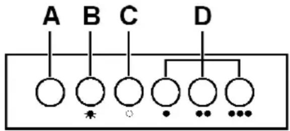
A – Power indicator light
B - Light button
C - Power off button
D - Speed level buttons
flowchart
graph TD
    A["A"] --> C["C"]
    B["B"] --> C["C"]
    C["C"] --> D["D"]
    D["D"] --> C["C"]
    C["C"] --> E["•"]
    C["C"] --> F["•"]
    C["C"] --> G["•"]
    C["C"] --> H["•"]
Fig. 1
To switch the extractor light on or off
- Press button B.
To switch on the extractor or to change the speed at any time when the extractor is running
- Press the relevant D button for the first, second or third speed level as required.
To switch the extractor off
- Press the C button.
Care and Maintenance
IMPORTANT : DO NOT PERFORM MAINTENANCE OR CLEANING OF THE EXTRACTOR WITHOUT FIRST SWITCHING OFF THE ELECTRICITY SUPPLY.
Cleaning
You should use a nonabrasive cleaner. Any abrasive cleaner (including Cif) will scratch the surface and could erase the control panel markings.
You can clean your extractor effectively by simply using a dilute solution of water and mild detergent and drying to a shine with a clean cloth, for example the CDA E-Cloth.
Cleaning the grease filter
The grease filter should be kept clean to minimise the risk of fire.
At least once a month you should remove and clean the grease filter with hot soapy water. You can also wash the grease filter in a dishwasher, ensuring that you place it in an upright position to prevent damage from other items in the dishwasher. After rinsing and drying, replace the filter.
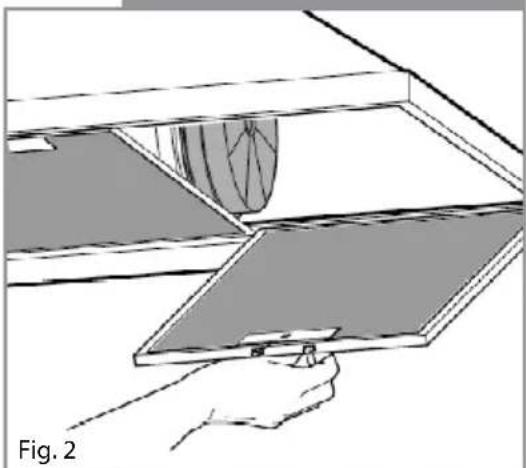
To remove the grease filter, push in the button on the handle and then pull down on the filter at the front as shown in figure 2. When you have released it at the front, then you can pull the filter out completely.
Please note:
Cleaning the grease filter in the dishwasher may lead to discoloration. This is normal and does not constitute a fault with the appliance.
Changing the charcoal filter (re-circulating only)
To ensure best performance of your extractor, you should replace the charcoal filters every four to six months, depending on use. To attach a new charcoal filter, first remove the grease filter as described above. Then offer up the charcoal filter to the side of the motor as shown in figure 3 and turn it clockwise until it locks into place.
natural_image
Illustration of a hand holding a tablet with a curved screen above it, labeled 'Fig. 2' (no text or symbols on the diagram itself)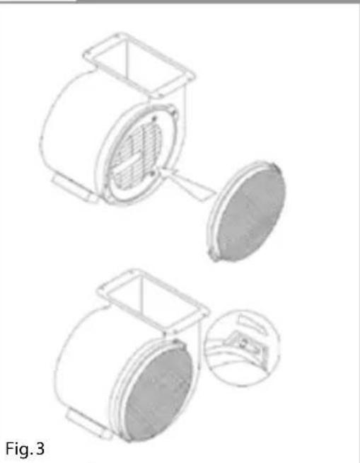
natural_image
Technical line drawing of a mechanical device with two views: top shows internal structure, bottom shows close-up of a component (no text or symbols)Changing the Light
DO NOT CHANGE THE LIGHT BULB IMMEDIATELY AFTER USE AS THE BULB WILL BE HOT. ALLOW IT TO COOL BEFORE REMOVING IT.
Remove the grease filter, unscrew the light bulb and replace the light with the required light bulb as shown below. Finally, replace the grease filter.
| ECH | 50W max halogen 2 pin GU10 |
Table 1
Do not touch bulbs or adjacent areas during or straight after prolonged use of the lights.
The light is designed for use during cooking and not for general room illumination. Extended use of the light can reduce the life span of the bulb.
Bulb replacement is not covered by the guarantee.
Only use bulbs recommended for your extractor. Do not fit bulbs of a higher power rating. Bulbs of a lower power rating may be adequate for use, generally last longer and use less energy.
Spare bulbs are available from CDA Customer Care or from your local DIY shop.
Mains Electricity Connection
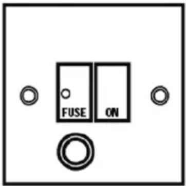
THIS APPLIANCE MUST BE CONNECTED TO THE MAINS SUPPLY BY A COMPETENT PERSON, USING FIXED WIRING VIA A DOUBLE POLE SWITCHED FUSED SPUR OUTLET AND PROTECTED BY A 3A FUSE.
We recommend that the appliance is connected by a qualified electrician, who is a member of the N.I.C.E.I.C. and who will comply with the I.E.E. and local regulations.
The wires in the mains lead of this appliance are coloured in accordance with the following code:
BLUE = NEUTRAL, BROWN = LIVE.
As the colours of the wires in the mains lead for the appliance may not correspond with the coloured markings identifying the terminals connecting to the fused spur, proceed as follows:
- The wire which is coloured blue must be connected to the terminal marked N (Neutral), or coloured black.
- The wire which is coloured brown must be connected to the terminal marked L (Live), or coloured red.
- If the mains cable is damaged, it must be replaced by a CDA approved engineer, agent or similarly qualified persons in order to avoid a hazard.
NOTE: USE A 3A FUSE
Assembly and electrical connection should be carried out by competent personnel.
When installing this product we recommend you seek the help of another individual.
IMPORTANT: THIS APPLIANCE IS A CLASS II APPLIANCE (DOUBLE INSULATED) AND IS NOT INTENDED TO BE EARTHED. DO NOT FIT AN EARTH LEAD TO THIS EXTRACTOR.
Do not mount the isolation switch behind the chimney section. It is a requirement that you must be able to isolate the extractor from the mains electrical supply after installation.
This appliance is intended to be connected to the mains electrical supply by means of an isolation switch and fused spur and is intended to be protected by a 3A fuse. The use of a 13A fuse can cause damage to the internal wiring in the event of a fault, and may also invalidate the warranty.
DOUBLE POLE SWITCHED
FUSED SPUR OUTLET
text_image
FUSE ONUSE A 3 AMP FUSE
Electrical Information
Mains electrical voltage: 230 - 240Vac
Total rated power consumption: 240W
Troubleshooting
Please note:
Your extractor is equipped with a motor protection device that will switch off the motor to prevent damage from overheating. This may happen during cooking when most or all of the zones/burners are being used simultaneously, or if your extractor is installed incorrectly, lower than the recommended height.
This is normal, and the extractor will work again once the motor has cooled sufficiently.
If your extractor is not working:
-
Check that the mains supply has not been switched off.
-
Check that the fuse in the spur has not blown.
Contact CDA Customer Care
A : Customer Care Department, The CDA Group Ltd, Harby Road, Langar, Nottinghamshire, NG13 9HY
T:01949 862 012 F:01949 862 003 E:customer.care@cda.eu W:www.cda.eu
Mounting your Extractor
When the extractor is to be installed above an electric hob, the minimum distance between the hob and extractor must exceed 600mm (650mm is recommended).
When the extractor is to be installed above a gas hob, the minimum distance between the hob and extractor must exceed 700mm (750mm is recommended).
If the instructions provided with your gas hob state that the required distance between the hob and extractor must be greater than 700mm, then that is the distance that should be observed; this is a legal requirement and may lead to your hob being disconnected from the gas supply and the installation being reported to RIDDOR (The height should be measured from the top of the burners).
IN THE ABSENCE OF ANY INSTRUCTIONS SUPPLIED WITH THE GAS HOB, THE MINIMUM DISTANCE BETWEEN THE HOB AND EXTRACTOR MUST BE AT LEAST 760mm.
The width of any hob must not be greater than the width of the extractor installed above it.
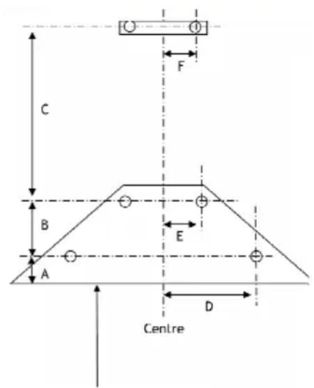
text_image
C B A E D CentreGas: 750mm recommended.
Electric: 650mm recommended.
natural_image
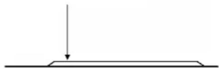
Simple line drawing of a horizontal surface with a downward arrow indicating direction (no text or symbols)Fig. 4
| ECH61/ECH71 | ECH91/ECH101 | |
| A | 55 55 | |
| B | 210 210 | |
| C | 400 400 | |
| D | 203 303 | |
| E | 75 75 | |
| F | 65 65 |
Table 2
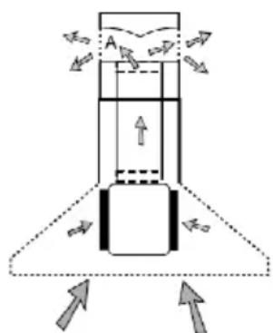
text_image
Diagram illustrating fluid flow around a container with labeled arrows and points A and B, likely representing a physics or engineering concept.Fig. 5
INSTALLATION
Tools required Mark wall as required (see table 2)
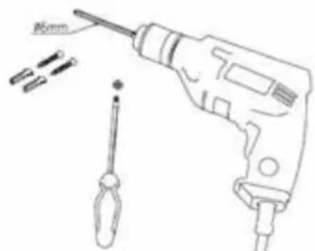
natural_image
Line drawing of a drill bit with screwdriver and 15mm mark (no text or symbols)Fig. 6 Fig. 7
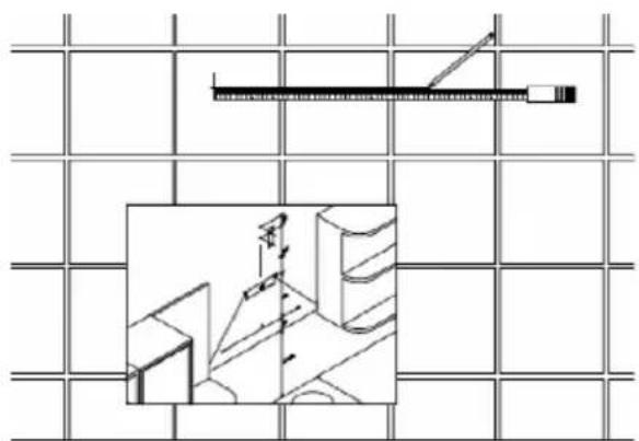
natural_image
Architectural line drawing of a room with a ruler and window, showing structural details (no text or symbols)Drill holes Fitwallfixingsandtopscrews-Ensurethatanyfixingsyouuse
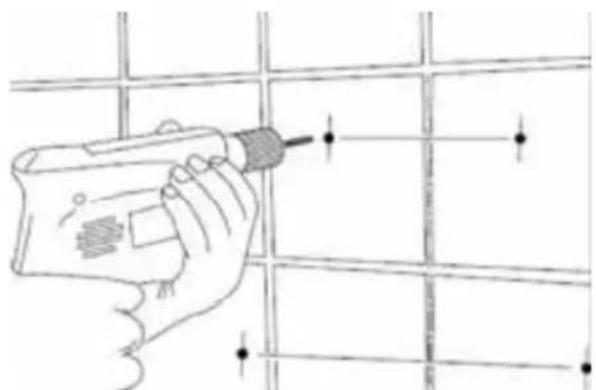
natural_image
Hand holding a tool on a grid surface, no text or symbols visibleFig. 8 Fig. 9
are appropriate for the wall type.
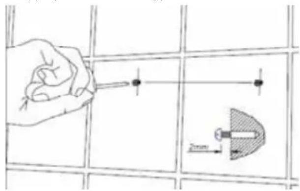
text_image
Technical diagram showing a hand using a screwdriver to adjust a component, with a 2mm scale indicator.Secure hood (tighten all screws) Fit ducting adaptor
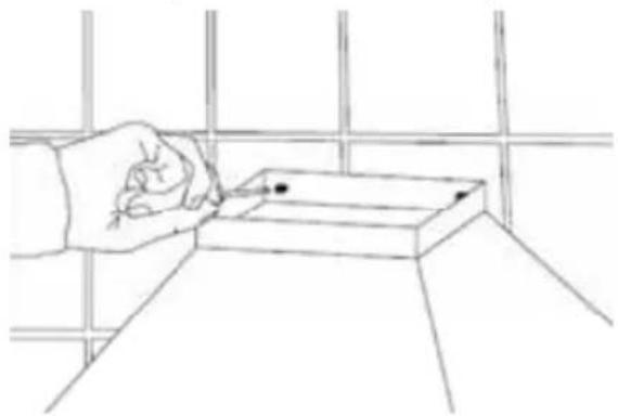
natural_image
Line drawing of a hand holding a pen above a rectangular object on a grid surface (no text or symbols)Fig. 10 Fig. 11
natural_image
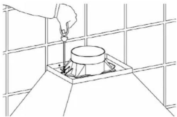
Line drawing of a hand using a tool to lift a cylindrical component into a square base, against a grid background (no text or symbols)IMPORTANT SAFETY WARNING: ONLY USE THE SCREWS PROVIDED WITH THE EXTRACTOR TO MOUNT THE DUCTING ADAPTOR. THE USE OF LONGER SCREWS MAY CAUSE DAMAGE TO THE INTERNAL WIRING WHICH WILL NOT BE COVERED BY THE GUARANTEE.
text_image
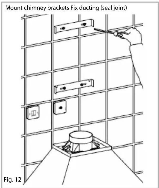
Mount chimney brackets Fix ducting (seal joint) Fig. 12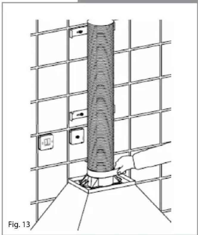
natural_image
Technical line drawing of a structural assembly with a vertical cylindrical component mounted on a grid base, no text or symbols present.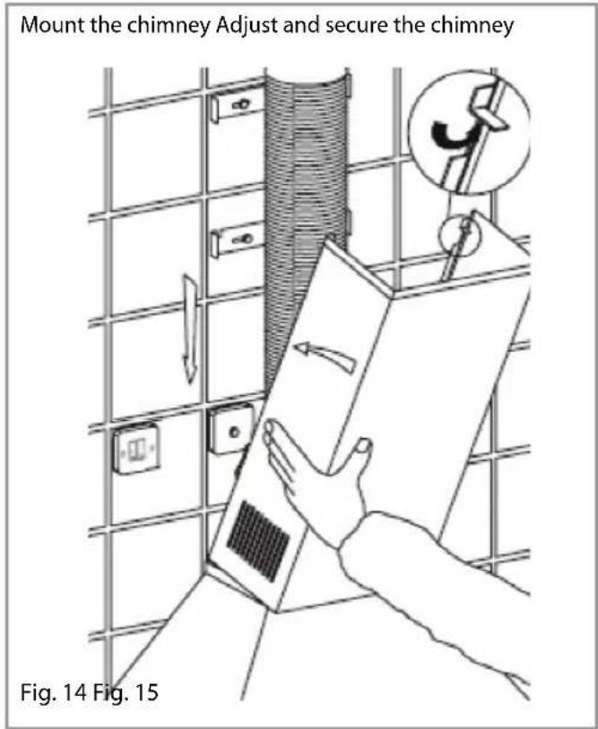
text_image
Mount the chimney Adjust and secure the chimney Fig. 14 Fig. 15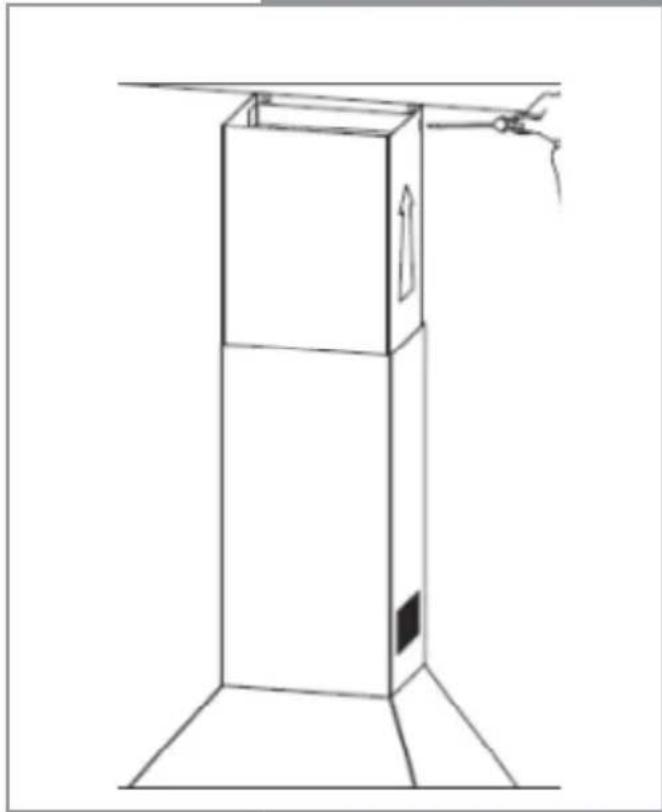
natural_image
Line drawing of a three-tiered rectangular box with a handle extending upward, no text or symbols presentDucting and Ventilation
For best performance and lowest noise output, we recommend the use of 125mm ducting. 100mm ducting may be used but this will reduce performance and increase the noise of the extractor.
| Energy Efficiency Information | |||
| Attribute Symbol Value Units | Symbol | Value | Units |
| Model Identification echxx | |||
| Annual Energy Consumption AEC | Hood | 135.4 kWh | |
| Time increase factor f 1.7 | |||
| Fluid Dynamic Efficiency FDE | Hood | 9.3 (E) | |
| Energy Efficiency Index EEI | Hood | 106.9 (E) | |
| Measured airflow at Best Efficiency Point | Q_BEP | 227.7 | m^3/h |
| Measured Pressure at Best Efficiency Point | P_BEP | 150.0 Pa | |
| Maximum airflow Q | MAX | 427.4 | m^3/h |
| Measured electric power at Best Efficiency Point | W_BEP | 102.5 W | |
| Nominal lighting power WL 100.0 W | |||
| Average illumination of the lighting system on the cooking surface | E_Middle | 665.0 | Lux |
| Measured power consumption in standby | P_S | NA | W |
| Measured power consumption off mode | P_O | 0.0 | W |
| Sound power level | L_WA | 64.0 | dBA |
| Grease Filter Efficiency | GFE_Hood | 80.5 (C) | % |
| Lamp efficiency | LE_Hood | 6.7 (F) | % |
E & O E. All instructions, dimensions and illustrations are provided for guidance only. CDA reserve the right to change specifications without prior notice.
|C|D|A
To contact our Customer Care Department, or for Service, please contact us on the details below.