
3L9 - Range hood CDA - Free user manual and instructions
Find the device manual for free 3L9 CDA in PDF.


| Brand | CDA |
| Model | 3L9 |
| Product Type | Ceiling-Mounted Range Hood (Recirculation) |
| Power Supply | 230-240 V ~ 50 Hz |
| Total Power Consumption | 290 W |
| Motor Speeds | 3 + Intensive (10 min) |
| Timer | Yes (15 min auto shut-off) |
| Clean Air Function | Yes (10 min every hour at speed 1) |
| Ambient Light Function | Yes (LED side lights) |
| Main Lighting | 4 x Halogen downlights (replaceable) |
| Ambient Lighting | LED (non-replaceable, lifetime) |
| Grease Filter | Washable metal filter (30-hour indicator) |
| Charcoal Filter | Replaceable (120-hour indicator) |
| Remote Control | Battery: 3V CR2032, range up to 5 m, magnetic base |
| Control Panel | Touch keys (Power, Speed, Light, Timer) |
| Installation Height | Min 650 mm above CDA hob / 760 mm for other hobs |
| Mounting | Ceiling (with supplied template and fixings) |
| Electrical Connection | Fixed wiring via double-pole switched fuse spur, 3A fuse |
| Safety | No steam cleaners; do not use silicone sealant; adequate ventilation required |
| Maintenance | Non-abrasive cleaner only; do not remove covers except by qualified personnel |
| Certification | CE |
Frequently Asked Questions - 3L9 CDA
User questions about 3L9 CDA
0 question about this device. Answer the ones you know or ask your own.
Ask a new question about this device
Download the instructions for your Range hood in PDF format for free! Find your manual 3L9 - CDA and take your electronic device back in hand. On this page are published all the documents necessary for the use of your device. 3L9 by CDA.
USER MANUAL 3L9 CDA
Manual for Installation, Use and Maintenance
C|D|A|
natural_image
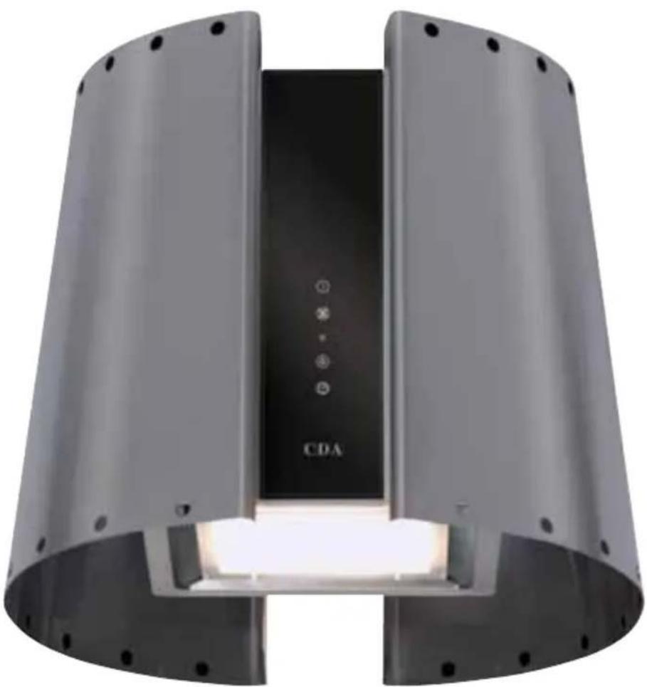
Exterior view of a modern cylindrical device with a central black panel labeled 'CDA' and illuminated light source (no additional text or symbols visible)
Important
The manufacturer cannot be held responsible for injuries or losses caused by incorrect use or installation of this product. Please note that the manufacturer reserves the right to invalidate the guarantee supplied with this product following incorrect installation or misuse of the appliance or use in a commercial environment.
This appliance is not designed to be used by people (including children) with reduced physical, sensorial or mental capacity, or who lack experience or knowledge about it, unless they have had supervision or instructions on how to use the appliance by someone who is responsible for their safety.
Under no circumstances should any external covers be removed for servicing or maintenance except by suitably qualified personnel.
Appliance information:
Please enter the details on the appliance rating plate below for reference, to assist CDA Customer Care in the event of a fault with your appliance and to register your appliance for guarantee purposes.
Appliance Model
Serial Number
CE Declarations of Conformity:
This appliance has been manufactured to the strictest standards and complies with all applicable legislation, including Gas safety, Electrical safety (LVD) and Electromagnetic interference compatibility (EMC).
IMPORTANT INFORMATION FOR CORRECT DISPOSAL OF THE PRODUCT IN ACCORDANCE WITH EC DIRECTIVE 2002/96/EC.
At the end of its working life, the product must be taken to a special local authority waste collection centre or to a dealer providing appliance recycling services. Disposing of a household appliance separately avoids possible negative consequences for the environment and health. It also enables the constituent materials to be recovered, saving both energy and resources. As a reminder of the need to dispose of household appliances separately, the product is marked with a crossed-out wheeled dustbin.

Please note:
- Under no circumstances should the extractor be connected to any gas ventilation system, flue system or hot air ducting system.
- Do not vent the extractor into an attic or loft space.
- Only house the extractor in rooms with adequate ventilation. Remember that the extractor is powerful and whatever air is extracted needs to be replaced.
- Do not tile the extractor in. It should be removable for service or maintenance.
- Do not use silicone sealant to secure the hood to the wall.
- You must be able to isolate the extractor from the mains electrical supply after installation.
• Steam cleaners must not be used when cleaning this appliance. - The performance of your extractor will vary depending on a number of factors. These include: type of extraction, length of ducting, room volume, ventilation available and cleanliness of the filters.
Using your Extractor
For best performance, you should switch on the extractor 15 minutes before starting to cook and leave it to run for approximately 15 minutes after the end of cooking.
To switch on the extractor and set the speed level
- Touch key A. The appliance will switch on at the first speed level.
- To increase the speed level touch key B. The speed cycles through first, second and third speed levels, and the relevant number indicator will show on the centre of the display.
• To switch the extractor off, touch key A.
The extractor lights
- To switch the lights on touch key D. The extractor lights will cycle through three light settings (high, medium, low, off) with each touch of the key. The light indicator will show on the centre of the display when the lights are on.
The intensive function
- The extractor is equipped with an intensive function which runs for ten minutes before returning to the previous selected speed level.
- To activate the intensive function, touch and hold key B at any speed level for approximately five seconds. The 3 indicator on the centre of the display will flash whilst the intensive function is on.
- To cancel the intensive function, touch the speed level key and the extractor will return to the previous speed level.
The timer
- The extractor is equipped with a timer that allows the extractor to run for 15 minutes before switching off automatically.
- To activate the timer, touch key E. The timer indicator will show on the centre of the display when the timer is on.
Please note
The timer cannot be activated when the intensive function is on.
The clean air function
- The extractor is equipped with a clean air function that switches on the motor for ten minutes every hour at speed level one.
- To activate the clean air function, touch key A for five seconds when the appliance is off. When the motor is running, the light indicator will flash and the first speed indicator will light up. For the remaining 50 minutes, the light indicator will flash.
- To cancel the clean air function, touch any key except the light key.
The ambient light function
- The extractor is equipped with an ambient light function that switches on the LED lights on the side of the extractor.
- To switch the ambient light function on or off, touch and hold the timer button for approximately five seconds

Control Panel
A - Power key
B - Speed level key
C - Light indicator
D - Light key
E - Timer key
Fig. 1
Using your Remote Control
Synchronising your remote with the extractor
- Whilst the appliance is off, touch the light key on the extractor for approximately five seconds until the indicator light begins to flash, as shown in figure 2.
- Turn the top section of the remote control until the indicator light on the extractor stops flashing.
In the event of any problems, repeat the steps above.
To set the motor speed
- Turn the top section of the remote control so the indicator is at the required speed level, as shown in figure 3.
- To select the intensive speed level, press the remote control in for two seconds at positions one, two or three, as shown in figure 4.
To turn on the light
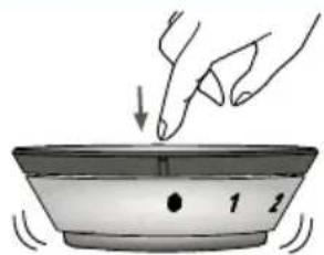
- Press the remote control in to switch on the light to the highest level, as shown in figure 5.
- To cycle through the light settings (high, medium, low, off) press the remote control in repeatedly.
To change the battery
• The battery will last for approximately 12 months, depending on usage.
- To change the battery, remove the lid from the remote control, as shown in figure 6.
- Then remove the battery by applying pressure to the edge, as shown in figure 7.
- Replace with a 3 Volt 5004LC / CR 2032 battery.
Please note:
The remote control will work up to five metres away from the extractor. The base of the remote control is magnetic so can be attached to ferrous surfaces.
Fig. 2

natural_image
Line drawing of a hand pressing a button on a black surface with a circular icon (no text or symbols)Fig. 3
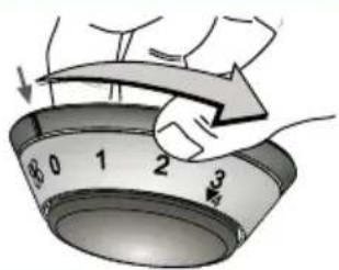
Fig. 4
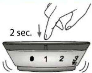
Fig. 5
natural_image
Illustration of a hand pressing down on a bowl with numbered markings (no text or symbols)Fig. 6

natural_image
Illustration of hands using a power tool to lift a curved surface, no text or symbols presentFig. 7

Care and Maintenance
IMPORTANT: DO NOT PERFORM MAINTENANCE OR CLEANING OF THE EXTRACTOR WITHOUT FIRST SWITCHING OFF THE ELECTRICITY SUPPLY.
Cleaning
You should use a nonabrasive cleaner. Any abrasive cleaner (including Cif) will scratch the surface and could erase the control panel markings.
You can clean your extractor effectively by simply using a dilute solution of water and mild detergent and drying to a shine with a clean cloth.
Cleaning the grease filter
The grease filter should be kept clean to minimise the risk of fire.
After 30 hours of use, the filters indicator light will switch on to indicate that the grease filters must be washed. you should remove and clean the grease filter with hot soapy water. You can also wash the grease filter in a dishwasher, ensuring that you place it in an upright position to prevent damage from other items in the dishwasher. After rinsing and drying, replace the filter. After the grease filter has been replaced, the electronic memory must be reset by touching the speed level key for approximately five seconds, until the filters indicator light switches off.
To remove the grease filter follow the steps below:
Pull open the handle on the grease filter as shown in fig. 8. It will release at the handle side. Then lower the grease filter to remove it completely.
To replace the grease filter, repeat the steps in reverse.
Please note:
Cleaning the grease filter in the dishwasher may lead to discolouration. This is normal and does not constitute a fault with the appliance.
Changing the charcoal filter
After 120 hours of use, the filters indicator light will flash to indicate that the charcoal filters must be replaced. After the charcoal filter has been replaced, the electronic memory must be reset by touching kthe speed level key for approximately five seconds, until the filters indicator light switches off.
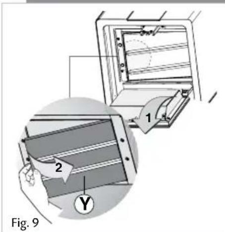
To replace the charcoal filter, first open the base of the extractor and remove the grease filter as shown in figures 8 and 9. To remove the charcoal filter as shown in figure 9 and replace it with a new charcoal filter. Finally, replace the grease filter and then close the extractor base.

Replacing the main halogen down lights:
- Lower the lamp panel (G) and unscrew the 4 lamp housing fixing screws (F) to access the bulb covers.
- Carefully prise off the bulb covers using a small screwdriver and refit the new bulb taking care not to touch the glass of the bulb (Fingerprints will lead to premature failure of the bulb)

Fig. 10
Replacing the ambient lighting side lamps
In normal use, the LED ambient lighting should not require replacement and is intended to last the lifetime of the product. In the event that these lights fail to operate, please contact our service department for repair.
Installation
IMPORTANT:
The extractor is intended to be mounted to the ceiling using fixings appropriate for the ceiling. Ensure that there is adequate ceiling strength and supports at the fixing points; if in doubt, consult a joiner or electrician.
INSTALLATION:
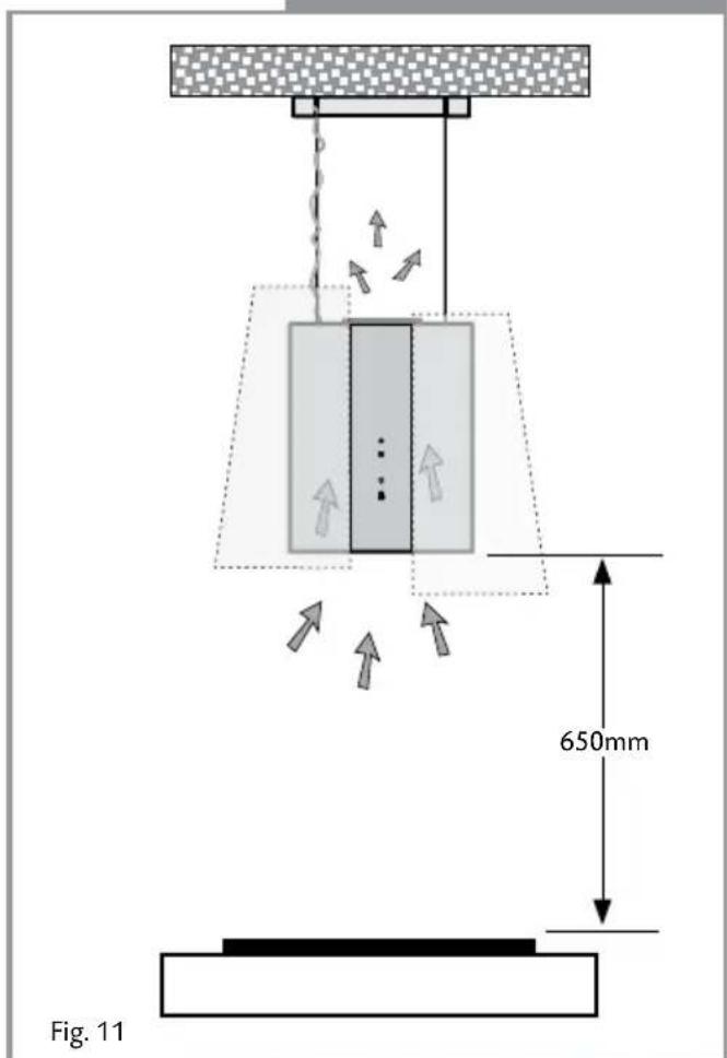
The extractor is intended to be operated as a re-circulation device suspended from the ceiling, as shown in Fig 11.
When installing this appliance over a CDA hob, the clearance between the extractor and the hob must be equal to or exceed 650mm. This instruction overrides the instructions supplied with the CDA hob. (The height should be measured from the top of the hotplates or burners)
Where the extractor is to be installed above a non-CDA hob, the instructions supplied with the hob may dictate that the height required above the hob is greater than 650mm.
IN THE ABSENCE OF ANY INSTRUCTIONS SUPPLIED WITH THE HOB, THE MINIMUM DISTANCE BETWEEN THE HOB AND EXTRACTOR MUST BE AT LEAST 760mm
Mounting The Extractor
-
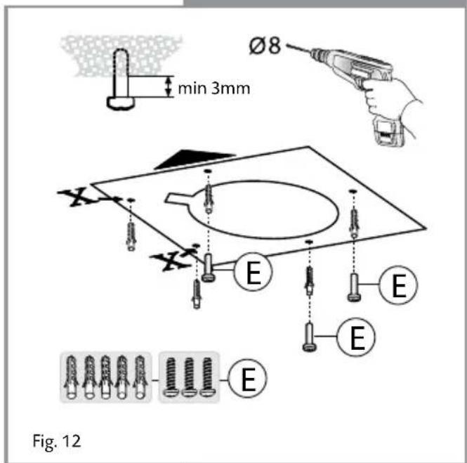
Using the supplied template, mark the positions of the 3 main fixing holes (E) and the 2 additional fixing holes (X) on the ceiling.
-
Drill and plug the holes, as required. If screwing directly to the ceiling joists, plugs may not be required (See Important note above)
-
Insert 3 screws (E) into the main fixings, leaving approximately 3mm protruding, as shown in Fig 12.
Mounting The Extractor
- Fit the ceiling support plate into position on the 3 screws and rotate it into position, as shown in Fig 13. Ensure that the mains supply cable is located in position and is not trapped or damaged.
- When in position, tighten the 3 main screws and fit 2 additional screws to fix the support plate in position.
- When used with a CDA hob, the extractor is required to be 650mm above the hotplates. Measure the height of the ceiling and then the hotplate height from the floor. The length of the wire supports should be calculated as follows: -
Length of cable = Ceiling height - (350 + 650 + Hotplate height)
Adjust the cables to the approximate required length (X in Fig 15). These can be adjusted after install, if required. Ensure that the cable is looped back through the second safety fixing (Y in Fig 15) to ensure there is no risk of the cables slipping.

flowchart
graph TD
    A["Central Circle"] --> B["X"]
    A --> C["X"]
    A --> D["X"]
    A --> E["E"]
    A --> F["E"]
    A --> G["E"]
    A --> H["E"]
    A --> I["E"]
    A --> J["E"]
    A --> K["E"]
    A --> L["E"]
    A --> M["E"]
    A --> N["E"]
    A --> O["E"]
    A --> P["E"]
    A --> Q["E"]
    A --> R["E"]
    A --> S["E"]
    A --> T["E"]
    A --> U["E"]
    A --> V["E"]
    A --> W["E"]
    A --> X["E"]
    A --> Y["E"]
    A --> Z["E"]
E

Fig. 13

Fig. 14
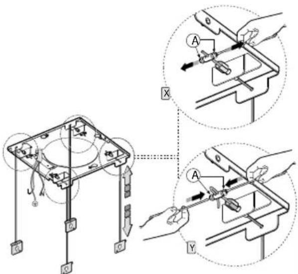
Fig. 15
Mounting The Extractor

Fig. 16
- Loosen the body fixing screws (G in Fig 16) by approximately 3mm and hook the cable fixing bracket into place. Lift the bracket into position and tighten the screw to lock the bracket in position, then insert an additional screw (H) for security.
- Make any adjustments to the cable length, ensuring that the extractor is level. Using 2 x 8mm spanners, the extractor can be levelled using the adjustment system Fig. 17
- Mount the mains connection box (S) to the ceiling support plate using the 2 supplied screws (D) and proceed to connect the appliance to the mains supply, as shown below. Once complete, secure the connection box lid with the 2 screws. If you are in doubt as to how to connect the appliance to the mains supply consult a qualified electrician.

Fig. 17
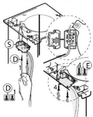
Fig. 18
Installation
- Fit the fixing support cover panel (C) and secure with the two supplied screws (A), as shown in Fig 19.
- Fit the extractor top panel, as shown in Fig 20, using the 8 supplied screws (G). Again, ensure that the mains supply cable is not trapped.
- Fit the 2 decorative curved panels (M1 and M2) to the body of the extractor as shown; note these can be installed offset as shown, or at the same level, as preferred. Insert the screws (X) into the body leaving approximately 3mm protruding. Hang the panels onto the body as shown, finally tightening the screws to secure the chimney, using a stubby screwdriver or spanner.

Fig. 21


Mains Electricity Connection
THIS APPLIANCE MUST BE CONNECTED TO THE MAINS SUPPLY BY A COMPETENT PERSON, USING FIXED WIRING VIA A DOUBLE POLE SWITCHED FUSE SPUR OUTLET AND PROTECTED BY A 3A FUSE.
We recommend that the appliance is connected by a qualified electrician, who is a member of the N.I.C.E.I.C. and who will comply with the I.E.E. and local regulations.
The wires in the mains lead of this appliance are coloured in accordance with the following code:
Green & Yellow = Earth, Blue = Neutral, Brown = Live.
As the colours of the wires in the mains lead for the appliance may not correspond with the coloured markings identifying the terminals connecting to the fuse spur, proceed as follows:
- The wire which is coloured green and yellow must be connected to the terminal marked E (Earth) or coloured green.
- The wire which is coloured blue must be connected to the terminal marked N (Neutral), or coloured black.
- The wire which is coloured brown must be connected to the terminal marked L (Live), or coloured red.
Note: Use a 3A Fuse
Assembly and electrical connection should be carried out by specialised personnel.
When installing this product we recommend you seek the help of another individual.
Electrical Information
Mains electrical voltage: 230 - 240Vac, 50Hz
Total rated power consumption:
290W
Troubleshooting
If your extractor is not working:
- Check that the mains supply has not been switched off.
- Check that the fuse in the spur has not blown.
DOUBLE POLE SWITCHED
FUSE SPUR OUTLET

USE A 3 AMP FUSE
|C|D|A
To contact our Customer Care Department, or for Service, please contact us on the details below.
- C|D|A|
- Important
- Appliance information:
- CE Declarations of Conformity:
- IMPORTANT INFORMATION FOR CORRECT DISPOSAL OF THE PRODUCT IN ACCORDANCE WITH EC DIRECTIVE 2002/96/EC.
- Please note:
- Using your Extractor
- To switch on the extractor and set the speed level
- The extractor lights
- The intensive function
- The timer
- Please note
- The clean air function
- The ambient light function
- Control Panel
- Using your Remote Control
- Synchronising your remote with the extractor
- To set the motor speed
- To turn on the light
- To change the battery
- Care and Maintenance
- IMPORTANT: DO NOT PERFORM MAINTENANCE OR CLEANING OF THE EXTRACTOR WITHOUT FIRST SWITCHING OFF THE ELECTRICITY SUPPLY.
- Cleaning
- Cleaning the grease filter
- Changing the charcoal filter
- Replacing the main halogen down lights:
- Replacing the ambient lighting side lamps
- Installation
- IMPORTANT:
- INSTALLATION:
- IN THE ABSENCE OF ANY INSTRUCTIONS SUPPLIED WITH THE HOB, THE MINIMUM DISTANCE BETWEEN THE HOB AND EXTRACTOR MUST BE AT LEAST 760mm
- Mounting The Extractor
- Mains Electricity Connection
- THIS APPLIANCE MUST BE CONNECTED TO THE MAINS SUPPLY BY A COMPETENT PERSON, USING FIXED WIRING VIA A DOUBLE POLE SWITCHED FUSE SPUR OUTLET AND PROTECTED BY A 3A FUSE.
- Note: Use a 3A Fuse
- Electrical Information
- Total rated power consumption:
- Troubleshooting
- If your extractor is not working:
- |C|D|A
Brand : CDA
Model : 3L9
Category : Range hood