
EVX90SS - Range hood CDA - Free user manual and instructions
Find the device manual for free EVX90SS CDA in PDF.


| Product Type | Range Hood |
| Brand | CDA |
| Model | EVX90SS |
| Dimensions (W x D x H) | 900 mm x 500 mm x 600-1000 mm (adjustable) |
| Weight | 18 kg |
| Power Supply | 220-240 V, 50 Hz |
| Motor Power | 250 W |
| Max Extraction Rate | 650 m³/h |
| Noise Level (max) | 65 dB(A) |
| Filter Type | Aluminum grease filter (washable), optional charcoal filter |
| Lighting | 2 x 4 W LED |
| Controls | Electronic push buttons |
| Speed Settings | 3 speeds + intensive mode |
| Energy Class | A+ |
| Duct Diameter | 150 mm |
| Installation Type | Wall-mounted, chimney |
| Material | Stainless steel |
| Air Extraction Mode | Ducted or recirculation (charcoal filter required) |
| Safety Features | Thermal cut-off protection |
| Warranty | 2 years |
Frequently Asked Questions - EVX90SS CDA
User questions about EVX90SS CDA
0 question about this device. Answer the ones you know or ask your own.
Ask a new question about this device
Download the instructions for your Range hood in PDF format for free! Find your manual EVX90SS - CDA and take your electronic device back in hand. On this page are published all the documents necessary for the use of your device. EVX90SS by CDA.
USER MANUAL EVX90SS CDA
3 Important information
5 Using your extractor
6 Care and maintenance
7 Installation instructions for standard fitting
15 Installation instructions for mounting the motor externally
15 Ducting
16 Recirculation
17 Mains electrical connection
18 Guarantee
19 Troubleshooting
20 Energy efficiency information
Important information
The CDA Group Ltd cannot be held responsible for injuries or losses caused by incorrect use or installation of this product. Please note that CDA reserve the right to invalidate the guarantee supplied with this product following incorrect installation or misuse of the appliance or use in a commercial environment. This appliance is not designed to be used by people (including children) with reduced physical, sensorial or mental capacity, or who lack experience or knowledge about it, unless they have had supervision or instructions on how to use the appliance by someone who is responsible for their safety. Under no circumstances should any external covers be removed for servicing or maintenance except by suitably qualified personnel.
Appliance Information:
Please enter the details on the appliance rating plate below for reference, to assist CDA Customer Care in the event of a fault with your appliance and to register your appliance for guarantee purposes.
| Appliance model | |
| Serial number |
Declarations of Conformity:
This appliance has been manufactured to comply with all EU & UK statutory requirements and complies with all applicable legislation and the following European Directives:
• The Low Voltage Directive 2014/35/EU
• Electromagnetic Compatibility Directive 2014/30/EU
The product has been marked with the UKCA and CE symbols.

This appliance is marked according to the European directive 2004/104/EC on Waste Electrical and Electronic equipment (WEEE).
IMPORTANT INFORMATION FOR CORRECT DISPOSAL OF THE PRODUCT IN ACCORDANCE WITH EC DIRECTIVE 2012/19/EU.
At the end of its working life, the product must be taken to a special local authority waste collection centre or to a dealer providing appliance recycling services. Disposing of a household appliance separately avoids possible negative consequences for the environment and health. It also enables the constituent materials to be recovered, saving both energy and resources. As a reminder of the need to dispose of household appliances separately, the product is marked with a crossed-out wheeled
dustbin.

Please note:
• Under no circumstances should the extractor be connected to any gas ventilation system, flue system or hot air ducting system
- Do not vent the extractor into an attic or loft space
- Only house the extractor in rooms with adequate ventilation.
Remember that the extractor is powerful and extracted air needs to be replaced
- Do not use silicone sealant to secure the hood to the ceiling
- You must be able to isolate the extractor from the mains electrical supply after installation
• Steam cleaners must not be used when cleaning this appliance - The performance of your extractor will vary depending on a number of factors. These include: type of extraction, length of ducting, room volume, ventilation available and cleanliness of the filters
Using your extractor
Controls
Power button
High speed button
Timer button

ON/OFF

LAMP

HIGH/+

LOB/-

TIMER

MIDDLE
Light button
Low speed button
Middle speed button
Fig. 1
Power button
Pressing once will start the extractor at the lowest speed setting, pressing again will turn the extractor off
Light button
Turn the lights of the extractor on or off
High speed button
Press to activate the highest speed setting, the display will show the number 3. Holding this button down for 3 seconds activates the booster function for 5 minutes and the display will show the letter B
Middle speed button
Press to activate the middle speed setting, the display will show the number 2
Low speed button
Press to activate the lowest speed setting, the display will show the number 1
Timer button
Pressing this button will activate the timer function and cause the display number to flash. The extractor will automatically turn off after 15 minutes. Changing the speed setting will not cancel this function. To cancel this function simply press the timer button again
Care and Maintenance
Cleaning
You should use a non-abrasive cleaner. Any abrasive cleaner (including Cif) will scratch the surface and leave marks on the extractor. You can clean your extractor effectively by simply using a dilute solution of water and mild detergent and drying to a shine with a clean cloth.
Removing and cleaning the grease filters
To remove the grease filter push in on the button on the handle and pull it down, when the catch is released at the front it can be removed completely. The grease filters should be kept clean to minimise the risk of fire, you should remove and clean the grease filters with hot soapy water. You can also wash the grease filters in a dishwasher, ensuring that you place them in an upright position to prevent damage from other items in the dishwasher. After rinsing and drying, replace the grease filter by reversing the removal process. Please note: Cleaning the grease filters in the dishwasher may lead to discolouration. This is normal and does not constitute a fault with the appliance.
Changing the charcoal filters (if fitted)
To ensure best performance of your extractor, you should replace the charcoal filter every four to six months, depending on use. To attach a new charcoal filter, first remove the grease filters as described above. Offer up the charcoal filter so that the magnetic pins are facing upwards, one to the rear and one to either side. The filter will be held in place by magnetic force. Finally, replace the grease filters
Installation instructions for standard fitting
Please note:
All installation measurements given are in millimeters
Make a cutout in the ceiling with the measurements below

Fig. 2
Dimensions for installation reference

Fig. 3
Fix the upper bracket to the support structure

natural_image
Technical line drawing of two structural supports with vertical supports and mounting holes, no text or symbols presentFig. 4
Fasten the lower bracket to the upper bracket with the 8 screws supplied. We recommend having an 85 - 100mm gap between the opening in the ceiling and the lowest point of the lower bracket

natural_image
Technical line drawing of two rectangular panels with internal supports and light beams, no text or symbols presentFig. 5
Fix the duct outlet to the extractor with the 4 screws supplied

natural_image
Technical line drawing of a mechanical assembly with no visible text or symbolsFig. 6
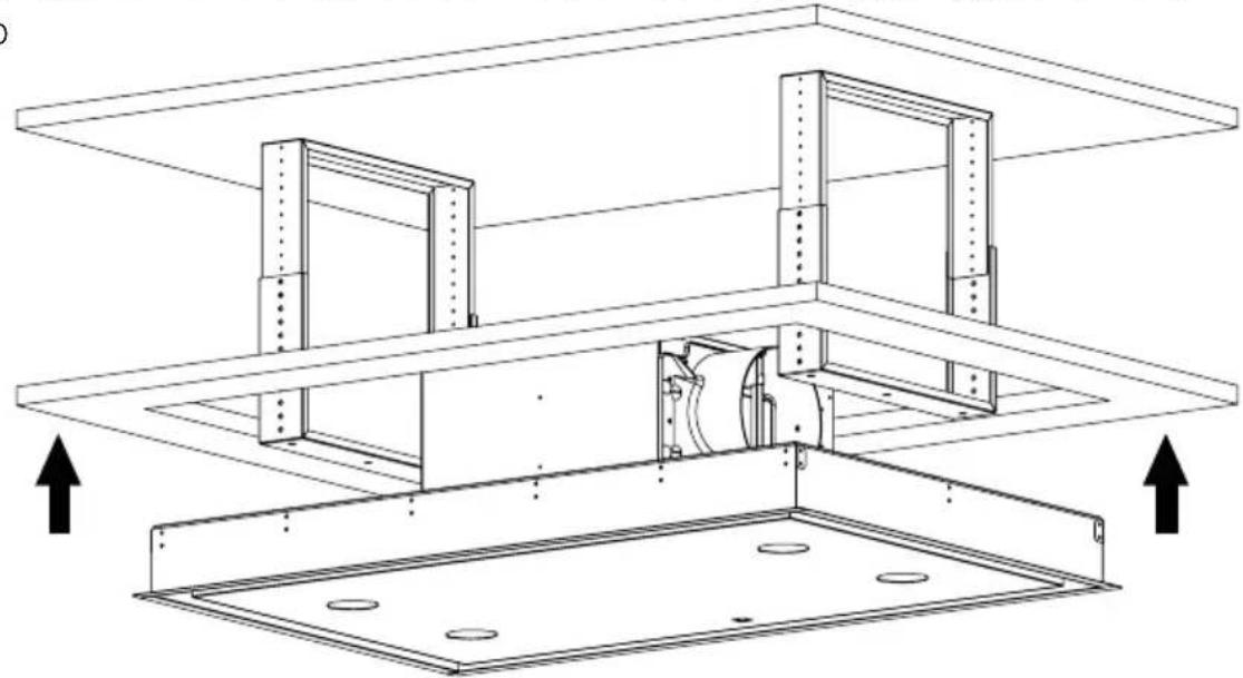
Locate the extractor in the ceiling opening, make sure to connect your ducting and mains electrical connection before proceeding to the next step
natural_image
Technical line drawing of a structural assembly with two main components and directional arrows indicating movement (no text or symbols)Fig. 7
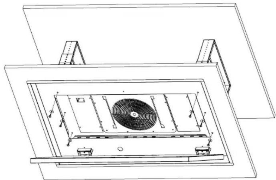
Fix the extractor to the bracket with the 6 screws and washers provided. Tighten evenly on both sides until secure, be careful to not overtighten
natural_image
Technical line drawing of a mechanical or electrical component with internal fan and mounting brackets (no text or symbols)Fig. 8
Installation instructions for mounting the motor externally
Remove the 8 screws fixing the motor housing on the extractor and detach it from the casing

flowchart
graph LR
    A["Rectangular Component"] --> B["Internal Structure"]
    B --> C["Circular Component"]
Fig. 9
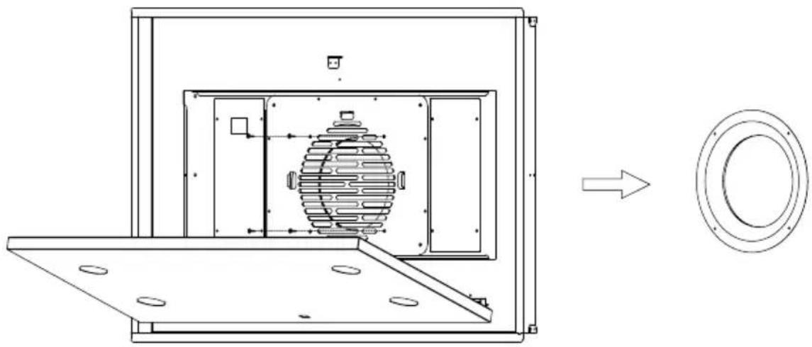
Remove the four screws that fix the airguide to the housing and remove it
natural_image
Technical line drawing of a mechanical device with internal components and a circular inset view (no text or symbols)Fig. 10
Connect the two duct adaptors on both of the panels

natural_image
Diagram showing a circular component with three curved arrows indicating rotational or feedback motion (no text or symbols)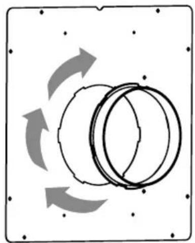
natural_image
Diagram showing a circular object with three curved arrows indicating rotational or feedback motion (no text or symbols)Fig. 11
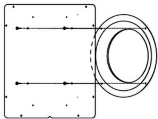
Fix the airguide to the panel using the four screws removed in Fig. 10; note that the air guide is fixed to the opposite side of the duct adaptor
natural_image
Pure electrical circuit lines without any symbols
natural_image
Pure diagram of concentric circular rings inside a square frame, no text or symbols present
Fig. 12
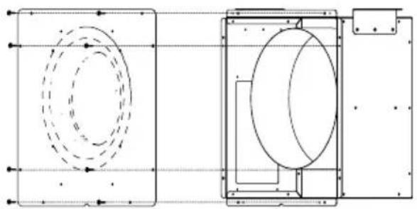
Fix the panel with the airguide to the motor housing with the 8 screws supplied; note that the airguide is facing the motor
natural_image
Technical line drawing of a mechanical component with two views: top shows a circular feature, bottom shows a cylindrical housing (no text or symbols)
natural_image
Pure diagram of concentric dashed circles inside a rectangular frame with no text or symbolsFig. 13
Secure the second panel to the rear of the extractor with the 8 screws supplied

natural_image
Technical line drawing of a mechanical or electrical component with no visible text, numbers, or symbols.
natural_image
Technical line drawing of a rectangular device with a central circular component and a vertical panel (no text or symbols)Fig. 14
Locate the extractor in the ceiling opening, making sure to connect your ducting and mains electrical connection before proceeding to the next step

natural_image
Isometric line drawing of a ceiling structure with mounting brackets and a central square component (no text or symbols)Fig. 15
Secure the motor housing to the support structure using appropriate fixings
Fig. 16

Suggested mounting example

natural_image
Technical line drawing of a ceiling-mounted room with internal components and mounting brackets (no text or symbols)Fig. 17
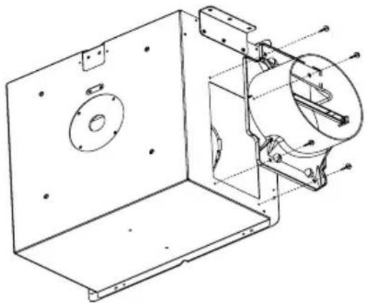
Fix the duct adaptor to the motor housing using the 4 screws provided
natural_image
Technical line drawing of a mechanical assembly with mounting brackets and internal components (no text or symbols)Fig. 18
Connect the motor and extractor body using a 150mm diameter ducting hose

natural_image
Technical line drawing of a mechanical assembly with no visible text or symbolsFig. 19
Ducting
The extractor can be used as a recirculation device or as an extraction device, depending on your installation.
The hood is more effective when used in extraction mode (ducted to the outside). When the extractor is ducted to the outside, charcoal filters are not required. The ducting used must be 150mm (6 inches), we recommend rigid circular pipe and must be manufactured from fire retardant material, produced to BS476 or DIN102-B1.
Wherever possible utilise rigid circular pipe which has a smooth interior, rather than the expanding concertina type ducting. The maximum length of ducting without performance being affected is as follows:
• 4 metres with 1 x 90° bend
• 3 metres with 2 x 90° bends
• 2 metres with 3 × 90^ bends
Longer ducting can be used but the performance of the extractor will be reduced.
Please note:
Ducting components and ducting kits are optional accessories and have to be ordered, they are not automatically supplied with the extractor. Use of ducting less than 150mm in diameter will affect the performance and increase the noise produced by the extractor
Recirculation
An internal air vent is required, as shown below. This ensures that the air is placed back in the kitchen after it has been filtered. The internal air vent must be a minimum of 2 metres away from the extractor

Extraction
The extractor is provided with a non-return butterfly valve which should be fitted over the vent outlet before the ducting is fitted. This prevents cold air being blown into the room from outside.
Securing the duct to the outlet
Note that the duct pipe should be secured and sealed to the vent outlet pipe/valve using appropriate ducting tape or a securing clamp.
LED lighting
In case of malfunction of the illumination system contact the technical service.

flowchart
graph TD
    A["LEDLED"] --> B["Person Icon"]
    B --> C["Sun Icon"]
Replaceable (LED only) light source by a professional
Mains electrical connection Warning! This appliance must be earthed.
This appliance must be connected by a competent person, using fixed wiring via a double pole switched fused spur outlet, protected by a 3A fuse.
We recommend that the appliance is connected by a qualified electrician, who is a member of the N.I.C.E.I.C. and who will comply with the I.E.T. and local regulations. The wires in the mains lead are coloured in accordance with the following code:

GREEN AND YELLOW = EARTH BLUE = NEUTRAL BROWN = LIVE
As the colours of the wires in the mains lead for the appliance may not correspond with the coloured markings identifying the terminals in your spur box, proceed as follows:
- The wire which is coloured green and yellow must be connected to the terminal marked E (Earth) or coloured green
- The wire which is coloured blue must be connected to the terminal marked N (Neutral) or coloured black
- The wire which is coloured brown must be connected to the terminal marked L (Live) or coloured red
Guarantee
Your new product is guaranteed against defect in materials and/or workmanship. Any parts found to be defective will be repaired or replaced at our discretion. All repairs must be carried out by an authorised repair agent. Your appliance comes with a 5 year parts and 2 year labour guarantee if registered within 30 days of purchase.
This guarantee is valid providing that:
• The appliance has been installed by a suitably qualified person
• Installation has been carried out in accordance with instructions and current legislations
• Proof of purchase can be produced
- The appliance has been used for domestic purposes only
- The appliance has not been tampered with or repair attempted or modified by any unauthorised person
This guarantee does not cover:
- Damage by misuse, neglect or transit
• Use of parts not used or recommended by CDA
• Routine maintenance, general wear, tear and installation faults - Rubber seals, removable glass and/or plastic parts, fuses or light bulbs which all need replacing periodically
• Second hand or reconditioned appliances
• Appliances used for commercial or professional purposes
Troubleshooting
In the event of your appliance requiring technical assistance and/or spare parts, please contact CDA Customer Care.
In this case it is necessary to state all the appliance data on the rating plate, such as model, serial number etc. This information can be found behind the grease filters
CDA Customer Care
Phone: 01949 862 012
Email: customer.care@cda.eu
Problem Reason Solution
| The appliance does not work | No power/ power outage Check the fuse, replace if blown |
| Wires have disconnected | |
| Output of appliance is low | Setting is too low for amount of fumes present |
| Inadequate ventilation in the kitchen | |
| Charcoal filter (if fitted) is blocked | |
| Ducting is obstructed Remove any obstructions from the ducting | |
| Exit flaps on the motor housing are restricted | |
| Extractor stops mid operation | There is a power outage Check the power supply |
| The circuit breaker or fuse has tripped | |
Energy Efficiency Information
| Attribute Symbol Value Units | |||
| Model Identification EVX90SS | |||
| Annual Energy Consumption AEC | Hood | 68.8 kWh | |
| Time increase factor f1.0 | |||
| Fluid Dynamic Efficiency FDE | Hood | 27.1 | |
| Energy Efficiency Index EEI | Hood | 62.6 | |
| Measured airflow at Best Efficiency Point Q | BEP | 378.8 m^3/h | |
| Measured Pressure at Best Efficiency Point P | BEP | 423 | Pa |
| Maximum airflow | Q_Max | 675 | m^3/h |
| Measured electric power at Best Efficiency Point | W_BEP | 164.5 | W |
| Nominal lighting power | WL | 7.3 | W |
| Average illumination of the lighting system on the cooking surface | E_Middle | 677 | Lux |
| Measured power consumption in standby | P_S | / | W |
| Measured power consumption in off mode | P_O | 0.46 | W |
| Sound power level | L_WA | 69 | dBA |
| Grease filter efficiency | GFE_Hood | 46.6(F) | % |
| Lamp efficiency | LE_Hood | 92.7(A) | % |
Notes
Notes
Notes
The CDA Group
Harby Road
Langar
Nottinghamshire
NG13 9HY
Sales Department
Phone: 01949 862010
Email: sales@cda.eu
CDA Customer Care
Phone: 01949 862012
Email: customer.care@cda.eu

- Important information
- Appliance Information:
- Declarations of Conformity:
- IMPORTANT INFORMATION FOR CORRECT DISPOSAL OF THE PRODUCT IN ACCORDANCE WITH EC DIRECTIVE 2012/19/EU.
- Please note:
- Using your extractor
- Controls
- Power button
- Light button
- High speed button
- Middle speed button
- Low speed button
- Timer button
- Care and Maintenance
- Cleaning
- Removing and cleaning the grease filters
- Changing the charcoal filters (if fitted)
- Installation instructions for standard fitting
- Installation instructions for mounting the motor externally
- Ducting
- Recirculation
- Extraction
- Securing the duct to the outlet
- LED lighting
- Mains electrical connection Warning! This appliance must be earthed.
- Guarantee
- This guarantee is valid providing that:
- This guarantee does not cover:
- Troubleshooting
- CDA Customer Care
- Notes
Brand : CDA
Model : EVX90SS
Category : Range hood