Atlantic - Solarium Dr. Kern - Free user manual and instructions
Find the device manual for free Atlantic Dr. Kern in PDF.


User questions about Atlantic Dr. Kern
0 question about this device. Answer the ones you know or ask your own.
Ask a new question about this device
Download the instructions for your Solarium in PDF format for free! Find your manual Atlantic - Dr. Kern and take your electronic device back in hand. On this page are published all the documents necessary for the use of your device. Atlantic by Dr. Kern.
USER MANUAL Atlantic Dr. Kern
natural_image
Exterior view of a modern office building (no signage)D
GB
E
CE IP 20

АЯ56
Assembly Instruction and operation manual for tanning unit Atlantic.... 14 - 24
natural_image
3D rendering of a rectangular electronic device with a flat top and curved sides, labeled 'Abb. 1' at bottom right (no other text or symbols)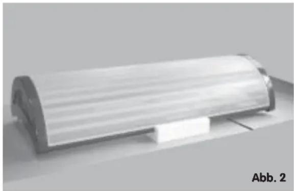
natural_image
Exterior view of a cylindrical mechanical component (no visible text or symbols)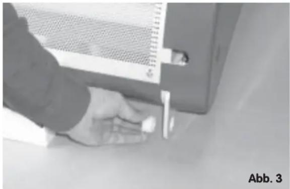
natural_image
Close-up of a hand holding a small object near a metal bracket (no visible text or symbols)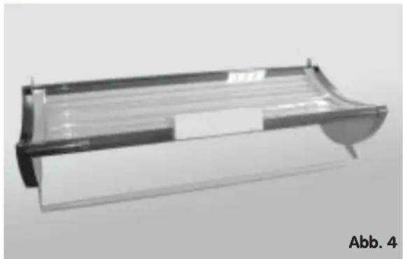
natural_image
3D rendering of a rectangular electronic device with a curved handle and internal components (no text or symbols visible)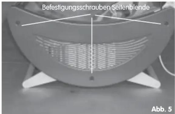
natural_image
Close-up of hands operating a mechanical device with a cylindrical component (no visible text or symbols)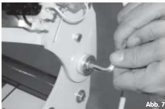
natural_image
Close-up of a hand adjusting a small mechanical component with a metallic hook (no visible text or symbols)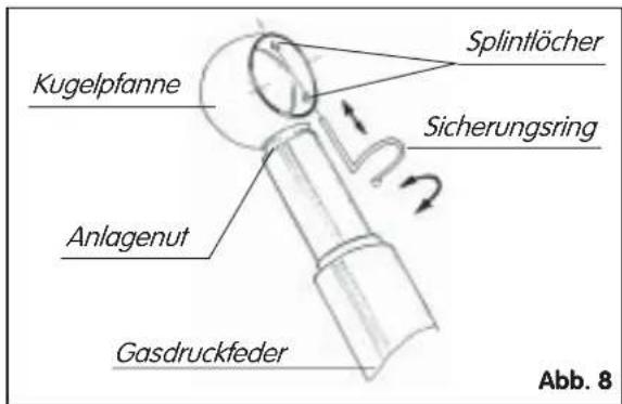
natural_image
Person standing beside a large cylindrical object, possibly a machine or device, with no visible text or symbols.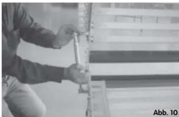
natural_image
Person using a tool on a mechanical component, no visible text or symbolsnatural_image
Close-up of hands using a tool to trim a car body panel (no visible text or symbols)natural_image
Close-up of gloved hands assembling electronic components on a surface (no visible text or symbols)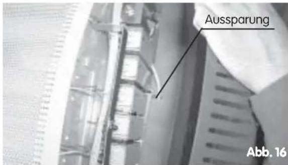
text_image
Aussparung Abb. 16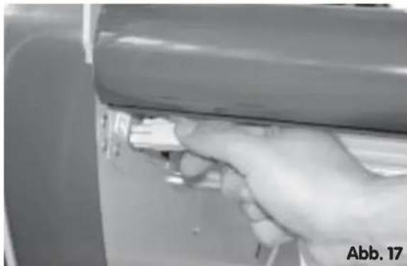
natural_image
Close-up of a hand gripping a car trunk, no visible text or symbols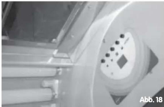
natural_image
Close-up of a mechanical component with a circular dial and small black dots, labeled 'Abb. 18' in the corner (no readable text or symbols beyond label)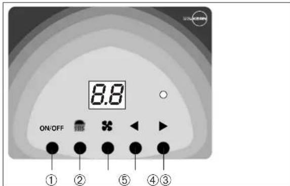
text_image
ON/OFF 8.8 ① ② ⑤ ④ ③natural_image
Close-up of a hand holding a transparent cylindrical object, possibly a mechanical component or tool, with no visible text or symbols.Interesting facts about tanning 14
Special instructions 14
General safety precautions 14
Tanning program 15
Tanning distance 15
After tanning 15
Skin types 15
Assembly of the tanning system 16
Assembly of the gas pressure springs 17
Assembly of the Duo-body fan (optional) 18
Initial operation 19
Body fan....20
Timer adjustment 20
Repair and maintenance 20
Changing lamps and starters 20
Maintenance of the face tanner (type 24/1) 21
Technical data....22
Replacement parts 23
Guarantee 23
Important notes
●The tanning appliance is intend for a connection to a separate protected earthing contact socket (230 V AC 50 Hz) with safety device H 16 A.
●In the event of power cable replacement, only type H05W-F 3 G 1.5 (3 x 1.5 ^2 ) may be used.
●Always disconnect the system from the power source when performing work on the system (replacement of tubes/bulbs and starters or cleaning operations).
●Repairs to the tanning system may be carried out by a locally certified electrician or by plant customer service personnel.
●The tanning system must be installed in a dry room and kept free of exposure to spray or drop moisture.
●Relative humidity in the air of 70% as well as room temperature from 15°C to 28°C must not be exceeded. A higher room temperature also means an increase in temperature of the surface on the bench and under the canopy.
● The air-intake slots and hot-air exhaust openings on the cooling fans must not be blocked or covered, as the system may otherwise overheat.
- In case of fan failure - which results in unusual heating of the tanning appliance - turn the equipment off immediately.
●Special materials, which fade in case of light (for example painting), should also not be too long in the UV-light of the appliance.
- It is possible that lamps will flicker in new installations, or that moving shadow effects occur. These have no influence on the tanning performance. Slight blackening may also become visible at the ends of the lamps. This does not influence the function of the tanning appliance or the life expectancy of the lamps.
●Children are not aware of the dangers which may occur when operating electrical appliances. Children must therefore never be allowed to operate electrical appliances without supervision.
●This tanning appliance is not intended for commercial use for medical purposes.
●The acrylic shields are not compatible with certain types of cosmetics and cleaning agents on the market. Compatibility with our products ECOCLEAN have been tested and found to be harmless to the acrylic. We assume no liability for damage to the acrylic plates by chemical products of other manufacturers.
The filter glasses of the facial tanners become very hot during the tanning session. Please avoid any contact.
Tanning
Interesting facts about tanning
The radiation of the solarium is of an optimal composition. The special lamps emit a particularly large amount of mild UV-A tanning rays. This avoids sunburn, while allowing the skin to tan in the shortest possible time.
Aside from the cosmetic effects, reasonable exposure to tanning rays can promote overall physical well-being and may, in many cases, have a favourable influence on a variety of skin disorders. Persons with known skin or health disorders should consult a physician prior to tanning, however.
The tanning appliance can only produce its optimal tanning effect when the normal preconditions are present which are required for tanning in sunlight. The radiation of the tanning appliance will have no tanning effect on people whose skin does not tan in sunlight.
Special instructions
For installations with a built-in face tanner
-High pressure lamp-
The higher radiation output of a built-in face tanner results in better tanning than with the normal UV-A lamp. This higher output provides for intensive tanning of the facial skin, which also in normal sunlight tans more slowly than the rest of the skin on the body.
The face tanner can be turned ON = 1 or OFF = 0 with the switch on the control panel.
General safety precautions
UV appliances must not be used by persons who sunburn in sunlight without tanning their skin (Skin type I), persons who tend to suffer severe sunburning, children under 16 years of age, or by persons who have suffered from skin cancer or who have a tendency to do so.
The radiation distance has been determined by the manner in which the appliance has been built and must not be reduced under any circumstances.
Instructions concerning exposure times and intervals between tanning sessions must be followed.
Do not use the solarium if the time mechanism is faulty or if the filter glass is broken.
Ultraviolet exposure (=radiation) from the sun or from UV appliances can lead to damage to the skin or eyes. These biological effects depend on the type and quantity of exposure (radiation), as well on the sensitivity of the individual skin.
The skin may experience sunburn after increased exposure. Too frequent repetition of ultraviolet radiation from sunlight or from UV appliances can lead to premature aging of the skin as well as to an increased risk of skin tumours.
Unshielded eyes can suffer inflammation on the surface of the eye, and in some cases excessive exposure to UV light may damage the retina. Many repeated tanning sessions can lead to the formation of grey cataracts without the use of protective eyewear.
Special care must be taken in cases of special sensitivity in some individuals to ultraviolet radiation, as well as in cases where particular medications or cosmetics are being used.
●Healthy tan takes time!
Never take more than one sunbathe per day.
Always have a break for one day.
Recommendation:
Up to 10 sunbathes within 2-3 weeks. In the following time app. 2 sunbathes per week.
●Corresponding to your skin type is the beginning time for tanning. Please inform you with help of the tanning times table or your family doctor.
- Use the attached protection glasses for protecting your eye-lens.
●In case of you take medicaments, speak with your doctor before. Some medicaments can strengthen the effects of the UV-light and it exists a risk of skin damages.
- Remove carefully all cosmetics / Make up from your skin and take off all pieces of jewellery. Sunscreen should not be used as it has a negative effect on tanning intensity.
●Apart from this are all tanning lotions especially made for the sundbed. Before and after a sunbathe you should take care your skin with these special sun cosmetics. These care products are coordinated for the tanned skin and can also be used before tanning. Tanning lotions stimulate on the base of normal substances the melanin production. The skin tans more quicklier and the tan stays longer.
- If you see inflammation of the skin, allergic reactions or blisters, a medical discussion has to be done immediately.
When you follow these basic rules, there is nothing to prevent a relaxing sunbathe.
Tanning program
I Depending on the skin type and the radiation source integrated in your tanning appliance a tanning
programme was determined for your tanning appliance according to the recommendations of DIN 5050 and EN 60-335-2-27.
A sticker showing this tanning programme is adhered to your tanning appliance.
The shown beginning and highest radiation period may not be exceeded.
Tanning distance
he tanning distance is specific to the equipment model and must not be reduced under any circumstances
After tanning
Care your skin with a moisturizing cream after sunbathe. So your skin gets a fresh looking.
Skin types (max. tanning times)
| Skin type | Description | Designation | Reaction to sun | Limit of effectiveness of the body's natural defences to sunlight | |
| Sunburn | Tan | ||||
| I | Skin: Strikingly fair or paleFreckles: AbundantHair: ReddishEyes: Blue, rarely brownNipples: Very pale | Celtic type(2%) | is the only reaction; is severe and painful | No tan;inflammation turning white after 1-2 days; skin peels | 5-10 minutes |
| II | Skin: Somewhat darker than IFreckles: FewHair: Blond to brownEyes: Blue, green, greyNipples: Pale | Light-skinned European(12%) | Always occurs; is severe and painful | Little or no tan;skin peels | 10-20 minutes |
| III | Skin: Fair to light brownFreckles: NoneHair: Light or medium brownEyes: Grey, brownNipples: Darker | Dark-skinned European(78%) | Occurs more rarely; moderate | Average | 20-30 minutes |
| IV | Skin: Light brown, oliveFreckles: NoneHair: Dark brownEyes: DarkNipples: Dark | Mediterranean type(8%) | Little or no sunburn | Rapid and deep | 40 minutes |
Assembly of the tanning system
The system is delivered in two packing units on a pallet.
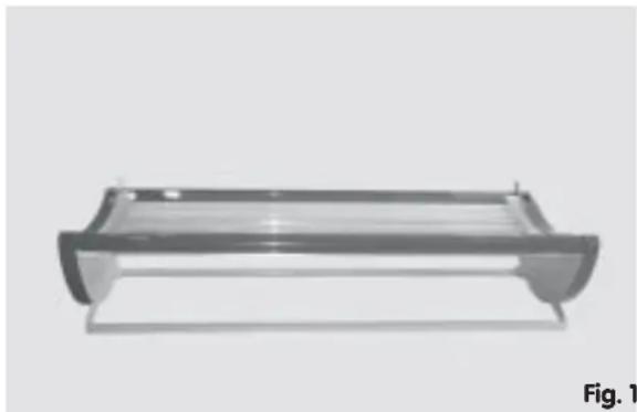
Begin the assembly with the lower section of the tanning bed. Open the box in which the bed is packed at the point marked "Hier oben" and lift the bed out of the packing. As the foot sections are already pre-assembled the tanning bed can stand on the foot sections immediately (figure 1).
Now open the packing box containing the upper section.
Lift the upper section out of the box and lay it down next to the bed. Use a layer of material under the equipment as protection, possibly cardboard or polystyrene pieces from the packing surrounding the equipment (figure 2).
Before assembling the upper section the plastic bearings from the plastic bag must be inserted from the inside into the drill holes for the bearing brackets on the right and left of the upper section (figure 3).
Lay a piece of polystyrene from the packaging onto the front longitudinal support of the bed to act as cushioning before the upper section is lifted into its correct position above the bed (figure 4).
Next remove the side surrounds from the bed and the upper section.
During this process remove the 3 plastic screws M4 (see figure 5 for an example) on the right and left outer sides of the surrounds. Use a large screwdriver or a normal coin for this.
Now lift the upper section above the bed in such a way that the front longitudinal supports on the upper section and the bed are positioned above one another on the cushioning.
natural_image
3D rendering of a rectangular electronic device with a curved top and base, labeled 'Fig. 1' at bottom right (no other text or symbols)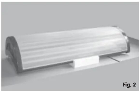
natural_image
Roll of white plastic or paper material on a flat surface, labeled 'Fig. 2' in the corner (no other text or symbols visible)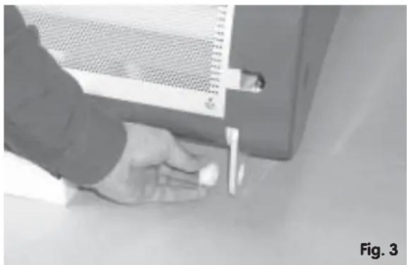
natural_image
Close-up of a hand holding a small object near a metal frame, no visible text or symbols
natural_image
3D rendering of a rectangular electronic device with internal structure and mounting bracket (no text or symbols)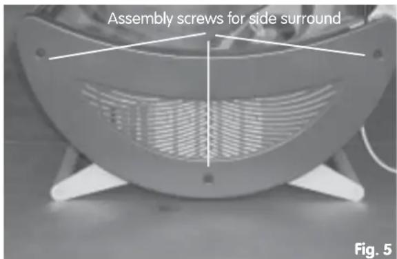
text_image
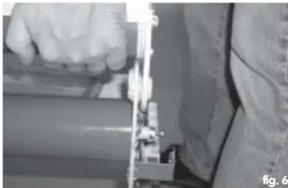
Assembly screws for side surround Fig. 5The drill holes in the bearing brackets of the upper section with the plastic bearings now attached must now be positioned to fit the drill holes in the bearing brackets of the bed. The upper section is lifted slightly at the back in this process (figure 6).
Please ensure that the bearing brackets on the upper section are positioned on the outside of the equipment in each case.
Now one bearing bush from the plastic bag is inserted in the plastic bearing from the outside on both sides and tightened with the screw DIN 912 M8x20 from the accessories bag (figure 7).
The upper section is now connected to the bed on both sides with a mobile joint.
Assembly of the gas pressure springs
Now the gas pressure springs are assembled, which keep the upper section in the open or closed position.
Security springs are clipped to each end of the gas pressure springs, which are found as a separate unit in the packaging. These springs must be removed as shown in figure 8.
In order to fit the gas pressure damper on the upper section this is swung so far open that the ball sockets can be easily pushed into the ball pins (figure 9).
As the side surrounds are removed you can see the ball joint bar on the upper section and in the bed on the equipment face, into which the joint socket of the gas pressure damper is engaged.
The gas pressure springs must now be assembled to the previously assembled ball pins on the bed and on the upper section. Hold the gas pressure spring, as shown in figure 10, with the ball socket over the ball pin and then press the ball socket onto the ball pin. Check if this connection has been made properly by briefly pulling against the joint.
Defective assembly of the gas pressure dampers is not possible as the gas pressure damper is fitted with different sizes of joint sockets above and below. Despite this it should be ensured that the pressure cylinder is on the top (figure 10).
natural_image
Close-up of a hand holding a mechanical component with visible wiring and components (no text or symbols)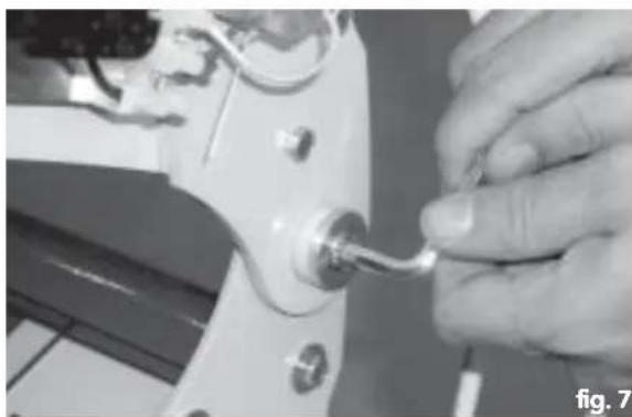
natural_image
Close-up of a hand adjusting a small mechanical component with a metallic hook (no visible text or symbols)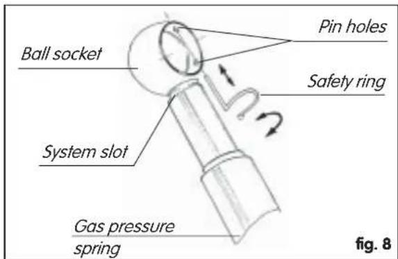
text_image
Ball socket System slot Pin holes Safety ring Gas pressure spring fig. 8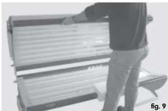
natural_image
Person standing beside a large cylindrical device with horizontal bars, possibly a solar or industrial machine (no visible text or symbols)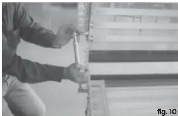
natural_image
Person using a tool on a mechanical component, no visible text or symbolsNow swing the upper section open and closed several times. You will notice that the upper section is pushed upwards by the gas pressure springs at the completely open position. When swinging the upper section downwards it moves easily downwards after initial slight resistance.
Please take account, however, of the fact that a slight discrepancy in pressure in the gas pressure spring can influence the swing movement somewhat.
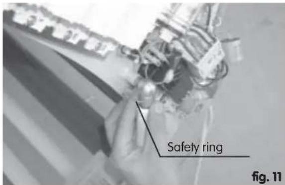
Please also make sure that the security rings on the ball sockets click back into place (figure 11). The assembly of the security rings is very important. The tanning system may only be used with perfectly fitted gas pressure dampers and security rings.
Subsequently the side surrounds can be fitted back onto the upper section and the bed in reverse order.
Assembly of the Duo-body fan (optional)
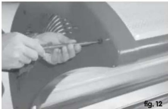
In order to be able to attach the body fan, first remove the side surround at the foot of the upper section.
In order to do this please remove the 3 assembly screws M4 at the right and left outer sides and the centre of the surround (figure 12).
natural_image
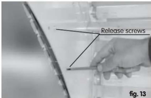
Close-up of hands using a tool to trim or trim a car body panel (no visible text or symbols)Please also remove the two centre screws (figure 13).
text_image
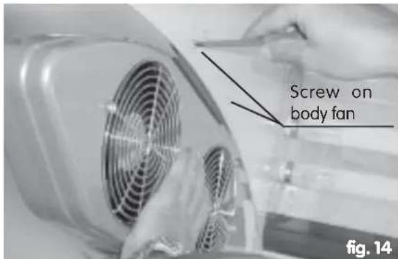
Release screws fig. 13The body fan can now be attached to the equipment in this position with the retainer sheet fitted in the upper area using the two screws that were previously removed (figure 14).
text_image
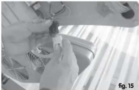
Screw on body fan fig. 14Then establish the electrical connection using the plug intended for this purpose (figure 15).
You may now re-attach the side surround to the equipment.
When doing this please ensure that the connection cable for the body fan is located in the corresponding recess in the side surround (figure 16).
Initial operation
Plug in the connection cable with the 4-pole equipment plug in the socket on the back of the bed (figure 17) and connect the tanning system to the mains using the connector cable.
Caution: only plug into a separate three-pin shockproof socket with 16 A fuse.
The tanning system is switched on at the digital timer (on the inside of the head end of the equipment (figure 18) by using the on/off switch ① (figure 19).
The desired tanning period is adjusted with buttons ④ und ⑤ (figure 19) to a maximum of 30 minutes, ⑤= upwards, ④= downwards.
After this period the timer switches the tanning system off automatically.
In the case of tanning systems with face tanning device this is switched on with button ② on the timer (figure 19).
The face-tanning device reaches its full tanning power after having been switched on for approximately 3 minutes.
If switched off and then switched on again immediately the lamp will only come on again after a period of approximately 3 minutes.
Body fan
The body fan can be switched on and off with button ③ on the timer (figure 19).
natural_image
Close-up of hands installing or adjusting a small component on a surface, no visible text or symbols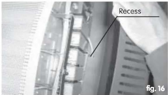
text_image
Recess fig. 16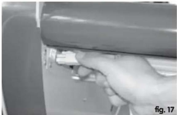
natural_image
Close-up of a hand holding a small object, possibly a tool or device, against a dark background (no visible text or symbols)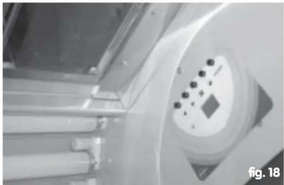
natural_image
Close-up of a mechanical device with a circular component and indicator lights (no visible text or symbols)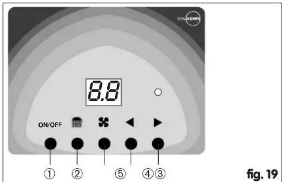
text_image
ON/OFF 8.8 ① ② ⑤ ④③ fig. 19Timer adjustment
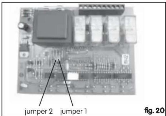
jumper 1 (time period): opened = maximum period 30 min closed = maximum period 60 min
jumper 2 (fan delay) opened = without fan delay closed = with fan delay
text_image
jumper 2 jumper 1 fig. 20Repair and maintenance
Changing lamps and starters
Remove the main plug before any maintenance work!
The tanning equipment can be operated for many years with correct use. The lamps have a very long usage period. In the event that the intensity of the radiation weakens then this can be strengthened again by exchanging the UVA low-pressure lamps and the face-tanning lamp.
In the event that a lamp should fail the acrylic sheet must be removed from the upper or lower section. In order to do this the surrounding cover must be removed on one side of the equipment. The acrylic sheet can then be pushed along in order to free the sheet on the side where the surround is still fitted.
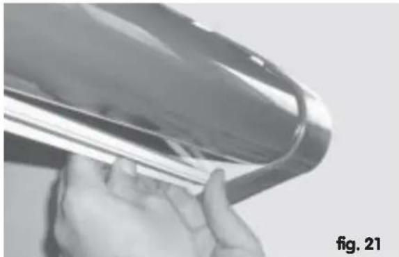
The acrylic sheets are fitted into the receiver slot of the longitudinal spar with initial tension. However if the sheet is push simultaneously backwards and downwards in the centre of the sheet (upwards for the upper section) towards the lamps then the sheet is released from the front longitudinal spar and can thus be removed (figure 21).
Try to solve a possible contact problem by gently turning the defective lamp backwards and forwards. If this is not successful then there many be a lamp or starter defect, which can be determined easily by yourself or by an electrician:
Turn the corresponding lamp 90°, so that it can be removed from the mounting. When inserting the new lamp first insert the lower pins, then pass the upper pins into the mounting and turn the lamp 90°.
In the event that the supposedly defective lamp functions in another position then the defect could be in the starters. This can also be tested by carrying out an exchange. Remove the starter by gently turning it to the left. Insert the new starter by turning to the right.
Then clean all the lamps and the acrylic glass sheet with a soft cloth and re-insert the sheet.
natural_image
Close-up of a hand holding a metallic object, possibly a tool or device, with no visible text or symbols.Maintenance of the face tanner (type 24/1)
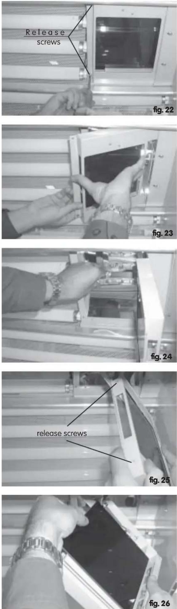
The filter cassette must be removed by releasing the marked screws before maintenance (figures 22 and 23).
In order to exchange the lamp in the face tanner this must be held on one of the flat lamp ends, pushed a little lengthwise and removed from the mounting (figure 24). The new lamp is inserted in the same way.
Please ensure that you do not touch the glass bulb. In the event that marks are made then the lamp must be cleaned with pure alcohol or spirit.
In order to clean the filter and/or the lower safety sheet this can be removed from the cassette (figure 26) by releasing both screws (figure 25).
When 're-inserting' the sheets please make absolutely sure that the filter sheet (see printing) is always inserted facing upwards, i.e. towards the face-tanning lamp.
The lamp in the face tanner becomes very hot during normal operation and must therefore be cooled with a cooling fan. The lamp is also fitted with a thermal safety fuse.
If the temperature rises above an acceptable level as a result of failure of the fan or a fall in power (caused by soiling or similar) then this fuse breaks the circuit to the face-tanning lamp.
As this break will only take place as the result of reduced cooling power the system must be inspected by a professional or the customer service centre.
The cause of the interruption can also, in very rare cases, be the fuse itself. This must not normally be changed.
Original parts must be used during all maintenance work.
Do not use the face tanner with a defective filter sheet. The use with a defective sheet will result in severe burning of the face.
Technical data
| Type | 24/0 | 24/1 |
| Lamps in canopy | VIVA Fun Power 100 W 2 m 1,0 % | VIVA Fun Power 100 W 2 m 1,0 %Dr. Kern excellent ER 100 W |
| facial tanner | - | HD-Brenner 400 w 230 V - R7S |
| lamps in bench | VIVA Fun Power 100 W 2 m 1,0 % | VIVA Fun Power 100 W 2 m 1,0 % |
| Power consumption (W) | 2.760 | 3.240 |
| Fuse protection (A) | 1 x 16 | 1 x 16 |
| Dimensions L x W x H (mm) | 2.160 x 890 x 925 | 2.160 x 890 x 925 |
| Weight (kg) | 174 | 178 |
Subject to technical modifications
Replacement parts
The service life of the UVA low pressure tubes and the face tanner bulb is approx. 500 hours. Ensure that genuine parts are used for replacement during all maintenance work.
The type designation of the UVA low pressure tubes, the face tanner tubes*) and the filter panels*) is also specified on the unit sticker (on the right rear next to the power cable).
Order these parts specifying the unit model no. (on the rating plate) from your service department or dealer.
- UVA low pressure lamp
VIVA Fun Power 100 W 2 m 1,0 %
Part No. 20012626 - UVA low pressure lamp
Dr. Kern excellent ER 100 W (only for type 24/1)
Part No. 20008772 - Starter Philips Cleo Power 100 - 180 W
Part No. 20002592 - High pressure lamp
400 w 230 v - R7s (only for type 24/1)
Part No. 20008812 - Filter glass for face tanner
Type Uvisol 85 175 x 165 x 3
(only for type 24/1)
Part No. 20009447 - Safety glass
175 x 165 x 2 (only for type 24/1)
Part No. 20009507
Instructions for disposal of packaging
All packaging and accessory material used by us bears the recycling trademark (Interseroh mark) and should thus be returned to an appropriate recycling center.
Place the paper, cardboard and corrugated packaging materials as well as the synthetic packaging into the appropriate containers or bins provided.
We allow only recyclable accessory packaging material

text_image
02** 05 06 PE PP PSIn the examples above, the materials listed stand for the following:
PE for polyethylene**
02 D PE-HD;
04 D PS-LD
Waste Disposal Act of 27.08.1986
Tanning lamps are not to be disposed of in domestic rubbish bins; rather, they must be disposed of separately (hazardous waste disposal).
Disposal of waste originating from private households and commercial sources is possible via municipal hazardous waste collection points. Lamps must be delivered to disposal sites intact.
Service address:
DR. KERN GmbH
Adolf-Weiß-Str. 43
35759 Driedorf, Germany
Tel.+49(0)277582-240
Fax +49 (0)2775 82-455
servicecenter@dr-kern.de
www.dr-kern.de
Please keep this address in a safe place, along with the Installation Guide. So that we may answer your questions quickly and competently, always give us the data contained on the ID plate, such as model number, article number and manufacture number.
Guarantee
The guarantee is taken over according to the legal regulations at present.
Manufacturer's warranty
- The period of warranty starts from the date of purchase and lasts up to 12 months.
- Always include the completed warranty certificate when returning equipment.
- The warranty expires for appliances which have been modified without manufacturer's explicit agreement.
- Damages caused by incorrect operation or handling through non-authorized persons are not covered under the terms of warranty.
- In the event of a claim, please indicate the serial number as well as the article code number and type name with expressive description of the fault.
- This warranty covers damaged parts but no defects due to wear and tear.
In case of complaint please return the equipment in its original packaging or other suitable packaging (caution: danger of transport damage) to our service department. Always include the completed warranty certificate when returning equipment.
Possible shipping costs arising from the transport to and from point of repair cannot be borne by us.
Always include the completed warranty certificate when returning equipment.
Outside of Germany please contact your specialist dealer in case of warranty claims. Direct warranty processing with our service department is in this case not possible.
Equipment start-up date:
Stamp and signature of the authorized electrician:
INDICE
Información útil 26
Bronceado 26
natural_image
3D rendering of a rectangular electronic device with a curved top and flat base (no text or symbols visible)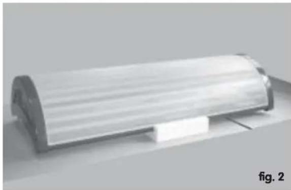
natural_image
Exterior view of a cylindrical mechanical component (no visible text or symbols)
natural_image
Close-up of a hand holding a small white object near a metal frame (no visible text or symbols)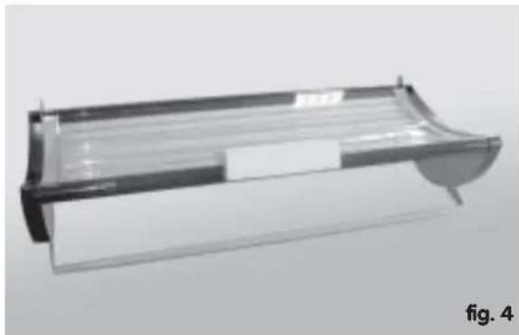
natural_image
3D rendering of a rectangular electronic device with a curved handle and internal structure (no text or symbols visible)
text_image
Tornillos plástivos M4 fig. 5natural_image
Close-up of a person using a mechanical device to interact with a cylindrical component (no visible text or symbols)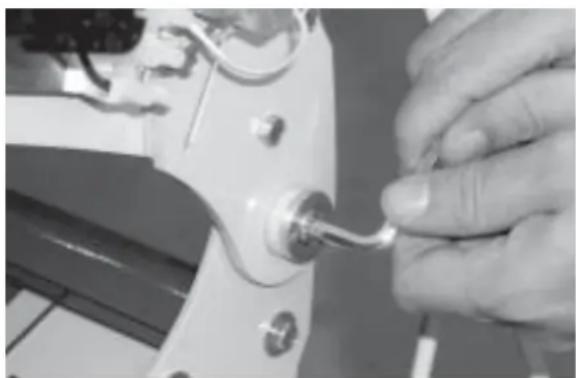
natural_image
Close-up of a hand adjusting a small mechanical component with a handle (no visible text or symbols)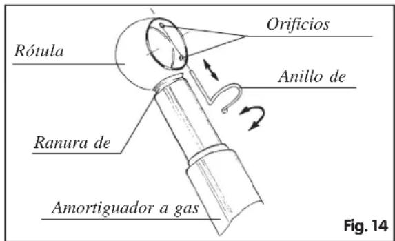
text_image
Rótula Orificios Anillo de Ranura de Amortiguador a gas Fig. 14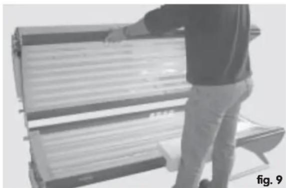
natural_image
Person standing beside a large cylindrical device with horizontal bars, possibly a machine or industrial machine (no visible text or symbols)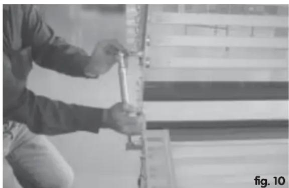
natural_image
Person using a tool on a wall-mounted device, no visible text or symbolsnatural_image
Close-up of hands using a tool to trim or trim a car body panel (no visible text or symbols)natural_image
Close-up of hands assembling electronic components on a surface (no visible text or symbols)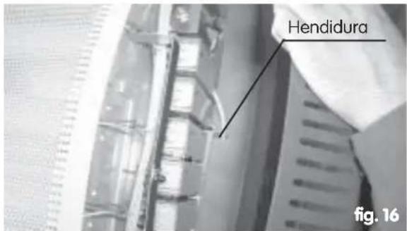
text_image
Hendidura fig. 16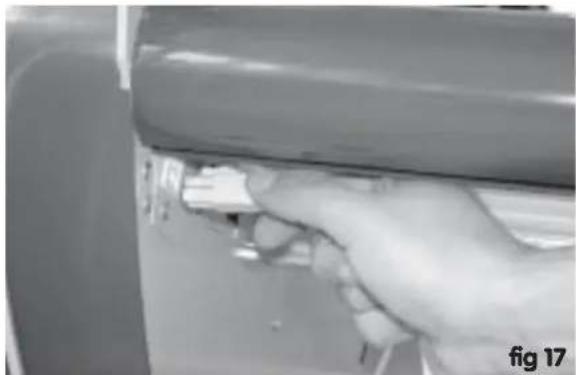
natural_image
Close-up of a hand holding a small object near a curved surface, possibly part of a device or mechanical component (no visible text or symbols)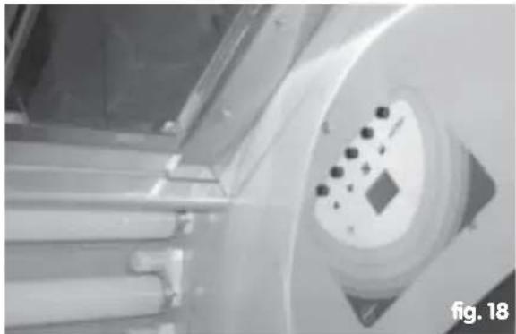
natural_image
Close-up of a mechanical component with a circular dial and small circular features, labeled 'fig. 18' in the corner (no readable text or symbols on the dial itself)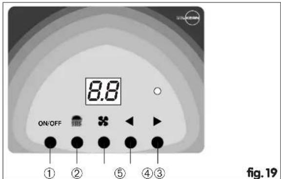
text_image
8.8 ON/OFF ① ② ⑤ ④ ③ fig. 19Ajuste del timer
Jumper 1 (tiempo)