Excellent 42/4 - Solarium Dr. Kern - Free user manual and instructions
Find the device manual for free Excellent 42/4 Dr. Kern in PDF.


User questions about Excellent 42/4 Dr. Kern
0 question about this device. Answer the ones you know or ask your own.
Ask a new question about this device
Download the instructions for your Solarium in PDF format for free! Find your manual Excellent 42/4 - Dr. Kern and take your electronic device back in hand. On this page are published all the documents necessary for the use of your device. Excellent 42/4 by Dr. Kern.
USER MANUAL Excellent 42/4 Dr. Kern
natural_image
Exterior view of a cylindrical electronic device with metallic casing and ventilation grilles (no visible text or symbols)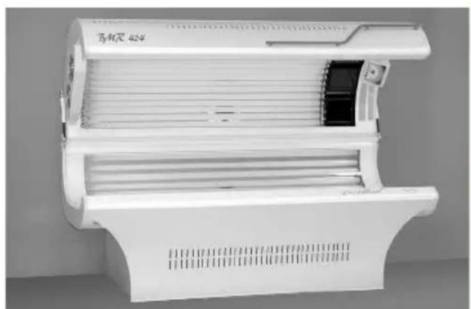
natural_image
White air conditioner unit with ventilation slots and ventilation ducts (no visible text or symbols)GB Assembly and operating instruction
English
Table of Contents
Interesting facts about tanning ....3
Important notes ....3
Information on tanning sessions ....5
Special Instructions for installations with a built-in face tanner ....6
Tanning plan ....7
Skin types 7
Safety distance 7
After tanning ....7
Assembly of the tanning appliance 8
Assembly of the bench 8
Assembly and Mounting of the Canopy 10
Mounting the Gas Spring 11
Electric plug-in unit 11
Mounting the ballast tray on sunbeds with standard base 12
Mounting the ballast tray on sunbeds with compact base 12
Operation 13
Body fan 13
Maintenance 14
Replacement of lamps and starters ....14
Maintenance of the face-tanner 15
Solarium cooling 16
Solarium cleaning 17
Cleaning of the acrylic glass 17
Spare parts 17
Technical data 18
Coin Box - for professional use 19
Switching to coin box operation 20
Returning to timer operation 20
Timer adjustment 20
Service address 21
Guarantee....21
Handling procedures for return shipments (RMA) - Details for all returns ! ......22
Dear Customer,
With your purchase of a Dr. KERN tanning system, you have opted for a technically superior, high-performance unit. Our production staff has made every effort to ensure the reliable, trouble-free operation of your Dr. KERN system.
There is also a great deal that you can do to enhance your satisfaction and extend the life of your tanning system. Please read the User's Guide carefully and install the equipment in accordance with the installation instructions enclosed. Proper installation is essential to flawless tanning system performance.
Interesting facts about tanning
The sun's natural rays give warmth, visible light and ultraviolet light. In regard to their effect on the skin, the UV spectrum is subdivided into the UV-A, UV-B and UV-C segments.
The longer UV-A waves are gentle to the skin, even at higher concentrations, and tan the pigments just beneath the surface of the skin. Light in the UV-B range is what initiates the formation of pigment, but it can also cause sunburn. The atmosphere shields us against the UV-C rays, which as a result do not reach the earth's surface.
Filtering out these UV-B rays almost entirely will effectively eliminate sunburn. But the production of melanine would then not be stimulated. This substance is converted into pigment in the cells at the surface of the skin; it then darkens under the influence of UV-A light, causing the skin to tan.
The pure and gentle UV-A light of the sun is very slow in causing a tan. Only at intensities higher than those of natural sunlight is UV-A able to tan the skin more quickly, by means of so-called direct pigmentation of the pigments already present in the skin.
With the tanning unit it is possible to get a direct and eudemic tan.
An essential precaution to be observed when using any such tanning appliance, is that possible overreactions in the skin be carefully observed; the following advice must be followed precisely.
Important notes

WARNING
Read instructions carefully.
- UV radiation may cause damages of the eyes and skin like skin ageing and possibly skin cancer. Certain medicine and cosmetics may increase the sensitivity.
- Persons not using the solarium, especially children, should not be present in the close proximity when the unit is in operation.
UV appliances must not be used by:
• persons under the age of 18 years;
• Persons who tend to freckle;
- Persons with the natural pale or reddish skin;
- Persons suffering from sunburn;
- Persons with abnormal skin discolorations or disorders;
- Persons having more than 16 moles (2 mm or larger in diameter) on the body;
- Persons having atypical moles (atypical moles are considered as asymmetrical moles with a diameter more than 5 mm with different pigmentation and abnormal lines; in case of doubt, seek medical advice);
- Persons not able to tan at all or not able to tan without burning when exposed to the sun;
- Persons who burn easily when exposed to the sun;
- Persons who repeatedly experienced severe sun burns during their childhood;
- Persons suffering from or previously suffering from skin cancer or predisposed to skin cancer;
- Persons with the next of kin having skin cancer.
- Persons with disorders arising out of increased sensitivity to light and undergoing treatment of such disorders;
- Persons with administered medication which increases or may increase sensitivity to light.
Exposures should not exceed a person's minimal erythemal dose (MED). If erythema (skin reddening) appears hours after any exposure, further exposure should cease. After one week, exposures could be restarted from the beginning of the schedule of exposure.
In case that after the first tanning session, secondary effects like itching should occur within 48 hours, please consult your physician before the next tanning session.
For the general advice concerning the recommended distance to the UV light source please refer to the chapter „Safety distance“.
For the general advice concerning the recommended tanning times and schedule please refer to the chapter “Tanning plan”.

WARNING
- This device has not been designed for being used by persons (including children) that are physically or mentally handicapped or have sensory disabilities. Moreover, it is not allowed to use this device without sufficient experience and/or knowledge, unless these persons will be supervised by persons responsible for their security or in case they have been instructed how to use this device.
- Children are not aware of the dangers which may occur when operating electrical appliances. Children must therefore never be allowed to operate electrical appliances without supervision.
- Do not use the appliance in bath rooms, damp rooms or near swimming pools.
- The tanning system must be installed in a dry room and kept free of exposure to spray or drop moisture.
- Prior to installation one shall ensure that the floor is capable to carry the static load of no less than 4,5 kN/m ^2 . Otherwise the floor must be reinforced properly and the valid proof of such reinforcement shall be presented.
- The installation surface must be absolutely level.
- Relative humidity in the air of 70% as well as room temperature from 15 °C to 28°C must not be exceeded. A higher room temperature also means an increase in temperature of the surface on the bench and under the canopy.
- Do not switch on the unit in any area where there may be explosive vapors.
In case of replacement or new connection of the connector cable, it is obligatory to use the type as described in the data sheet.
CAUTION

The air-intake slots and hot-air exhaust openings on the cooling fans must not be blocked or covered, as the system may otherwise overheat.
In case of fan failure - which results in unusual heating of the tanning appliance - turn the equipment off immediately.
Special materials, which fade in case of light (for example painting), should also not be too long in the UV-light of the appliance.
It is possible that lamps will flicker in new installations, or that moving shadow effects occur. These have no influence on the tanning performance.
Slight blackening may also become visible at the ends of the lamps. This does not influence the function of the tanning appliance or the life expectancy of the lamps.
CAUTION
UV lamps must be replaced against those who are mentioned on the lamps sticker of the tanning unit.
Alternative: Only the authorized service technician is allowed to change the lamps as recommended.
Repairs to the tanning system may be carried out by a locally certified electrician or by plant customer service personnel.

DANGER

Always disconnect the system from the power source with all poles when performing work on the system (replacement of tubes/bulbs and starters or cleaning operations).
This tanning appliance is not intended for commercial use for medical purposes.
The acrylic shields are not compatible with certain types of cosmetics and cleaning agents on the market. We assume no liability for damage to the acrylic plates by using unsuitable chemical products.
Information on tanning sessions
- The recommendations specific to the individual unit regarding the tanning times, radiation intervals and distancees must be observed.
- When using UV appliances for private use, people, especially children, who do not use the equipment have to be nonattendant during operation.
- Do not use the system if the time control unit is defective or the filter glass is broken or missing.
- Ultraviolet exposure (radiation) from the sun or from UV appliances can lead to irreversible damage to the skin or eyes. These biological effects depend on the type and quantity of exposure (radiation), as well as on the sensitivity of the skin of the individual.
- The skin may exhibit sunburn after excessive tanning. Overly frequent repetition of ultraviolet tanning sessions with sunlight or UV appliances may lead to premature aging of the skin as well as to an increased risk of skin tumors. Risks will increase with increasing UV tanning sessions.
- Without the use of protective eyewear, eyes can become inflamed on the surface, and in certain cases excessive exposure to UV light may damage the retina. Many repeated tanning sessions may lead to the formation of grey cataracts.
- In cases of particular sensitivity or allergic reaction of some individuals to ultraviolet radiation it is recommended to take medical advice.
Therefore, the following safety precautions must be observed:
CAUTION
- Always use the attached protective goggles. Contact lenses and sun glasses are no alternative for protective eyewear;
- Remove cosmetics in time for tanning and do not use any type of sunscreen agent or products, which speed up tanning.
- Certain medical conditions or secondary effects of drugs can be activated with UV radiations, consult your physician in case of doubt.
• Always leave a break of two days between the first and second tanning session - Do not have a natural sun bath and use a sunbed on one day;
- Strictly follow the recommendations for tanning times, intervals between tanning sessions and safety distance to UV light sources;
- Visit your physician if the skin displays persistent swelling, sores or pigmen-ted moles;
- Protect sensitive parts of the skin, like scars, tatoos and genitals against radiation.
Special Instructions for installations with a built-in face tanner
- High pressure lamp -
The higher radiation output of a built-in face tanner results in better tanning than with the normal UV-A lamp. This higher output provides for intensive tanning of the facial skin, which also in normal sunlight tans more slowly than the rest of the skin on the body.
Tanning plan
Using data which coordinates skin types (see table below) with the radiation source integrated in your tanning system, a tanning plan has been determined for your tanning system in accordance with the recommendations of EN 60-335-2-27.
This plan sticks on your tanning unit as an adhesive label or accompanies it.
If it is not available, please contact the manufacturer.

CAUTION
The beginning and maximum exposure times must not be exceeded.
Safety distance
The safety distance is determined by the construction of the solarium and must not be reduced under any circumstances.
The safety distance for vertical (stand-up) solariums is given in the chapter „Operation“.
After tanning
It is advisable to apply a moisturizing lotion on the skin after tanning for a fresh look of your skin.
Skin types
| Skin type | Description Designation Reaction to sun Limit of effective- | ness of the body's natural defences to sunlight | |||
| I Skin | strikingly fair or paleFreckles: abundantHair: reddishEyes: blue, rarely brownNipples. verry pale | celtic type(2 %) | is the only reaction;is severe and painful | no tan:infl ammation turning white after 1-2 days;skin peels | 5 to 10 minutes |
| II | Skin: somewhat darker than IFreckles: rarleyHair: blond to brownEyes: blue, green, greyNipples: pale | light-sikinned European(12 %) | always occurs;is severe and painful | little or no tan;skin peels | 10 to 20 minutes |
| III | Skin: fair to light brownFreckles: noneHair: light or medium brownEyer: grey, brownNipples: darker | dark-skinned European(78 %) | occurs more raely:moderate | average | 20 to 30 minutes |
| IV | Skin: light brown, oliveFreckles: noneHair: dark brownEyes: darkNipples: dark | mediterranean type(8 %) | little or no sunburn | rapid and deep | 40 minutes |

Persons with skin type I are not allowed to use a tanning unit (see warning).
Assembly of the tanning appliance Assembly of the bench
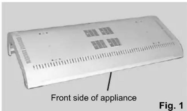
- Begin the assembly with the lower part - the tanning bench. Take the bench from the packaging and put it down on the floor with the lamp holding side down as shown in Fig. 1. As protection for the appliance use a pad, e.g. cardboard strips from the appliance packaging.
text_image
Front side of appliance Fig. 1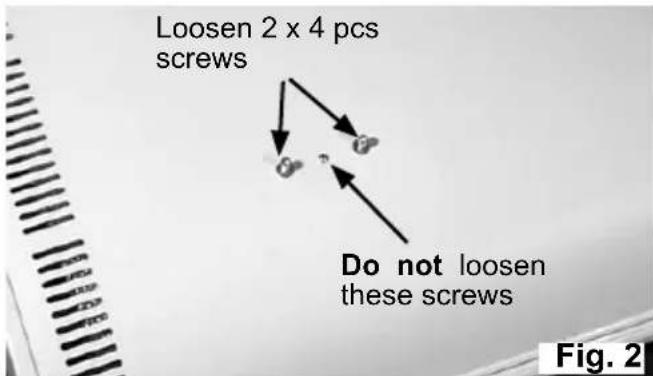
text_image
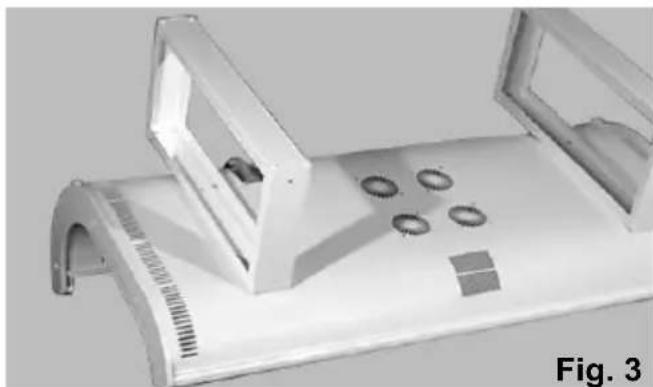
Loosen 2 x 4 pcs screws Do not loosen these screws Fig. 2- On the underside of the bench, which is on top now, the foot fastening screws are screwed in at eight places. Loosen these screws and attach the feet with them. Fig.2 and 3.
natural_image
3D rendered mechanical component with mounting holes and a curved base, labeled Fig. 3 (no text or symbols on the object itself)- Tighten screws.
If your solarium is equipped with the standard base version (curved shape), then execute the steps 4 to 8.
If your solarium is equipped with a compact base version, then execute the steps 9 to 14.
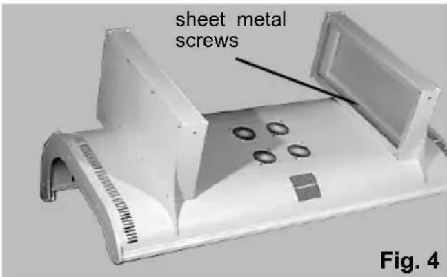
- Fix the lateral base covers to the feet's outside. The slightly grained surface of the covers is the appearance side which must be turned outside.
For the fi xing use 6 pieces of sheet metal screws 4.2 x 9.5 each from the accessories bag.
text_image
sheet metal screws Fig. 4- For the moment the assembly of the feet and covers is finished.
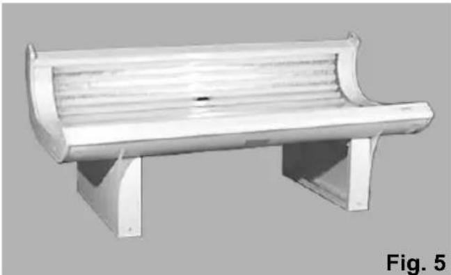
Now the bench must be set down on its feet at the intended place.
natural_image
3D rendering of a wooden bench with curved brim and two supports (no text or symbols)-
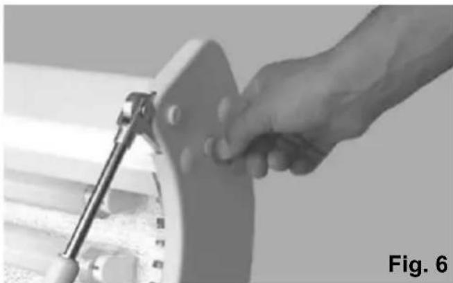
In preparation of the assembly of the upper part unscrew the upper fastening screws of the side cover on both sides. For this purpose use a big screwdriver or, if not at hand, a normal coin.
-
In preparation of the assembly of the upper part unscrew the upper fastening screws of the side cover on both sides. For this purpose use a big screwdriver or, if not at hand, a normal coin.
natural_image
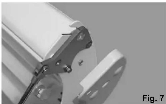
Close-up of a hand using a tool to adjust or install a mechanical component, labeled 'Fig. 6' (no text on the object itself)- After loosening the screw, press the side panel somewhat toward the outside. With the side panel remaining in that position, a screwdriver could become jammed or stuck therein. See fig. 7.
natural_image
Close-up of a mechanical assembly with metal clamps and a cylindrical component, labeled 'Fig. 7' (no readable text or symbols)-
At the top end of the sun-bed, plastic side plates have been mounted at the works, which are secured by furniture screws. For further assembly, the side plates must be removed again. For this purpose, use a large screwdriver or an ordinary coin.
-
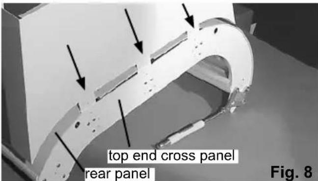
Now three recesses are visible in the rear panel of the sun-bed at each top end. Now insert the foot panel with the protruding brackets each into the gap between the rear panel and the top end brace and press the foot panel firmly to the rear panel of the apparatus. (Fig. 8).
text_image
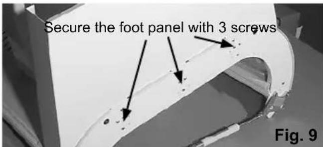
top end cross panel rear panel Fig. 8- Then secure the foot panel with three screws 4,2 x 9,5 from the accessory bag on the top end cross panel, as shown in fig. 9. Mount the second foot panel in the same manner on the other side of the top end of the apparatus.
text_image
Secure the foot panel with 3 screws Fig. 9-
This completes the assembly of the base and feet components. The bench can now be placed on its' feet in its' intended location.
-
The side panels of the bench can now be screwed on again. In doing so however, do not tighten the two top screws.
-
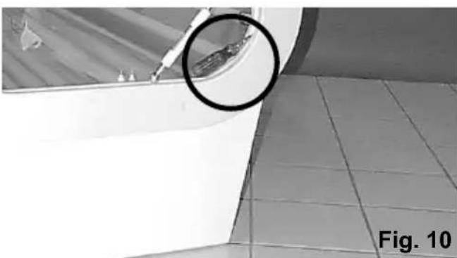
In order to prepare for the assembly of the canopy, press the side panels which have been screwe3d on previously outwards a little. To make sure that the side panels remain in this position, a screwdriver or something similar can be jammed in between, see fig.10
natural_image
Exterior view of a tiled room corner with a magnified circular detail (no text or symbols)Assembly and Mounting of the Canopy
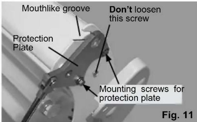
The last setup step on the bench was the loosening of the right and left side panels, which caused the protection plates to become free. These protection-plates cover the openings into which the canopy, with its rotating housings at either end, will be placed. Loosen the securing screws on the protection plates so that they can be turned away from the opening in the canopy to free them for mounting.
text_image
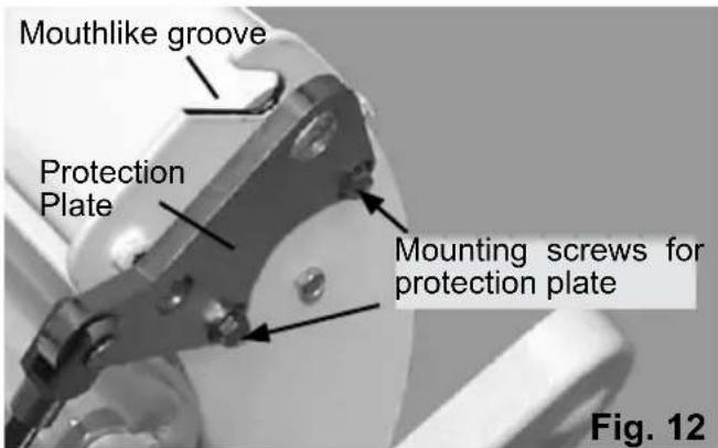
Mouthlike groove Don't loosen this screw Protection Plate Mounting screws for protection plate Fig. 11- Loosen the securing screws on the protection plates so that they can be turned away from the opening in the canopy to free them for mounting. See Fig. 11 and 12.
text_image
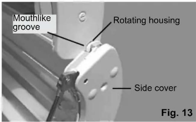
Mouthlike groove Protection Plate Mounting screws for protection plate Fig. 12- Two people may now lift the canopy out of its package and place both ends so that they can slide into the groove with the mouthlike opening. See fi g13
text_image
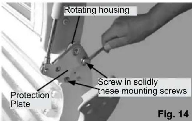
Mouthlike groove Rotating housing Side cover Fig. 13- With one person holding the canopy securely at the front, secure the canopy into the rotating housings. To this you must first place both protection-plates so that the big opening on the protection-plate grasps over rotating housings. See fig.14.
text_image
Rotating housing Screw in solidly these mounting screws Protection Plate Fig. 14- After you have placed both protection-plates at the left and right rotating housings, secure their respective securing screws with the enclosed SW 10 wrench.
Please oil the bearing before hooking up the canopy into the bench. Use any regular machine oil or vehicle grease.
- After the canopy has been properly and securely mounted, it can be let down onto the bench. Replace the side cover panels in the manner in which they were delivered.
Mounting the Gas Spring
- At the gas springs, which are already mounted at the protection plates, safety washers are fixed at the ball-joint connector. These safety washers have to be removed. See fig. 15.
- To insure proper securing of the gas spring, the canopy must be raised high enough so that the upper ball-joint connector can be snapped onto the ball-joint on the canopy.

text_image
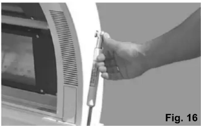
Cotter pin-holes Ball- jo int connector Safety washer Installation- groove Gas spring Fig. 15- Press the ball-joint connector onto the ball-joint as shown in fig 16.
natural_image
Hand holding a tool near a computer monitor (no visible text or symbols)Note! The ball-joint connectors have been lubricated at the factory with a special grease, which may not be removed.
- Before depressing the canopy downward, check the mounting of the gas springs and replace the securing clips on the ball-joint connectors to hold the ball-joints in place therein.
Replacement of the safety washers is very important; the canopy may not be moved without this first having been done.
- Move the canopy up and down a few times. You will notice that when the canopy is completely raised, the gas spring will move upwards. As the canopy is moved downward, a lighter resistance will be noticeable than at lower levels.
Be advised, however, that slight variations in resistance can occur. A lower or higher force variation in the gas spring can influence the difficulty or ease with which the canopy can be moved.
Electric plug-in unit
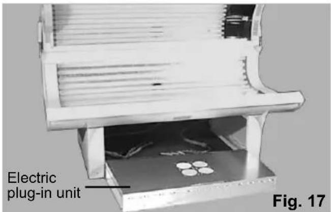
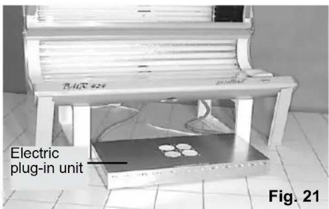
Your tanning appliance is provided with a separate electric plug-in unit (switch box). In this unit all electric components necessary for the operation of the lamps are integrated. Due to this extern arrangement the electric unit must be "electrically" connected to the bench and the upper part.
Installation of these connecting lines and the mains supply must be carried out by specialist staff.
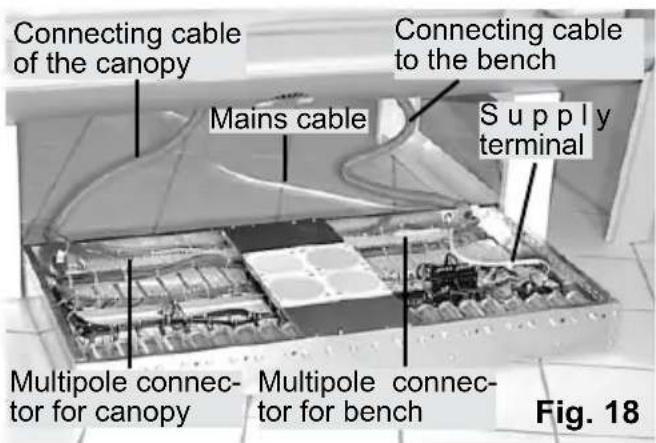
The assembly of tanning units with standard base is documented with Fig. 17 to 20 and for those with compact base with Fig. 21 to 24.
- For this purpose the electric unit (Packing unit 3) is placed between the feet as is shown in(Fig 17 resp.21).
- Upon dismounting of the cover the connecting cable of the upper part is plugged in the left multipole connector and the connecting cable of the bench in the right multipole connector (Fig 18 resp. 22).
- After installation of the screwed cable glands and the mains supply (5x1,5 ^2 ) the cover is reattached and the unit is completely pushed under the bench.(Fig 19 resp. 23).
- Attach the profi le cover strip delivered as part of the accessories on the front of the feet as shown in Fig. 19 resp. 23. Use two pieces of sheet metal screws 4.2 × 9.5 .
- Bear in mind that the open side of the groove points upwards.
- Place the front base cover in this groove and in the groove in the front longitudinal rail visible from below, as shown in Fig. 20 resp. 24. It will hereby bend to the outside.
- Through light pressure against the middle part of the cover it will "snap" into the right position.
text_image
Connecting cable of the canopy Mains cable Connecting cable to the bench Supply terminal Multipole connec- tor for canopy Multipole connec- tor for bench Fig. 18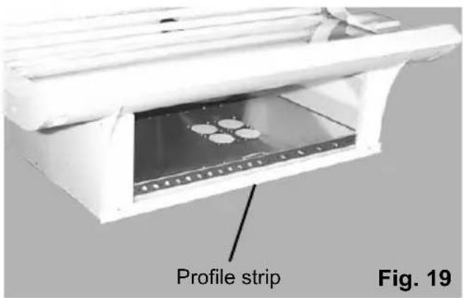
text_image
Profile strip Fig. 19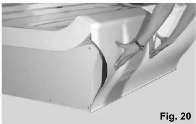
natural_image
Close-up of hands operating a white industrial machine component, labeled 'Fig. 20' (no visible text or symbols on the device itself)Mounting the ballast tray on sunbeds with standard base
text_image
Electric plug-in unit Fig. 17Mounting the ballast tray on sunbeds with compact base
text_image
Electric plug-in unit Fig. 21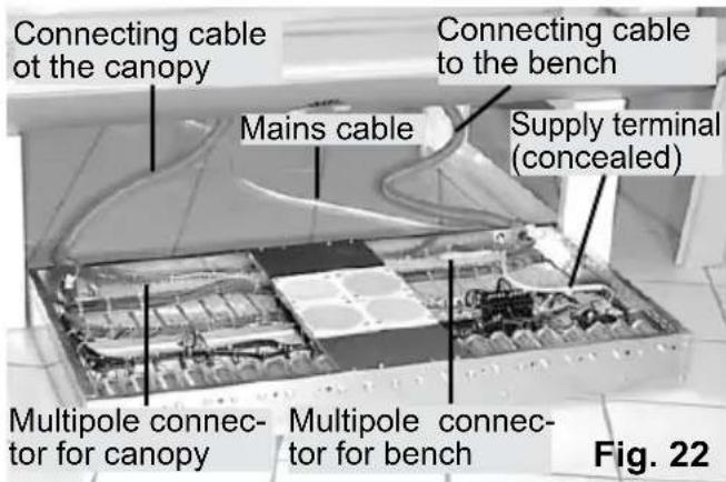
text_image
Connecting cable of the canopy Mains cable Supply terminal (concealed) Multipole connec- tor for canopy Multipole connec- tor for bench Fig. 22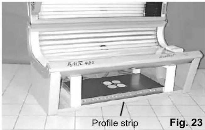
text_image
B/4尺 424 Profile strip Fig. 23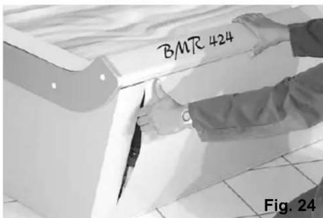
text_image
BMR 424 Fig. 24Operation
The solarium is switched on/off by pressing the “on/off” button (1) on the digital control panel located on the inner head side of the canopy (Fig. 25).
By pressing the arrow buttons (4) and (5) the desired tanning time duration may be set (max. 30 minutes).
$$ 5 = \text { up }, 4 = \text { down } $$
After the pre-set tanning time elapses the solarium switches off automatically.
When your solarium is equipped with the high pressure lamp(s) (HPL) you can them it (them) with the button (2) on the control panel (Fig. 25).
The HPL reaches its maximum power approximately 3 minutes after being switched on.
When the HPL is switched off and switched on again immediately it will start working after 3 minutes delay time.
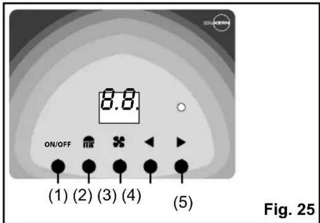
text_image
ON/OFF (1) (2) (3) (4) (5) Fig. 25Body fan
When your solarium is equipped with the body fan you can switch it on/off with the button (3) on the control panel (fi g. 25).
Maintenance
Replacement of lamps and starters
The solarium must be completely disconnected from the power supply by all maintenance works.
The acrylic glass sheet must be removed from the bench and/or canopy by replacement of the lamps or starter.
The acrylic sheet of the bench is held in the grooves of the longitudinal front and back rails without fastening screws.
text_image
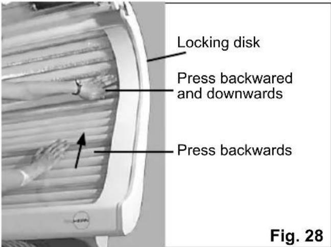
Locking disk Press backward and downwards Press backwards Fig. 28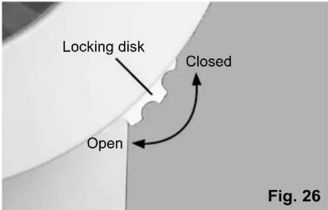
text_image
Locking disk Closed Open Fig. 26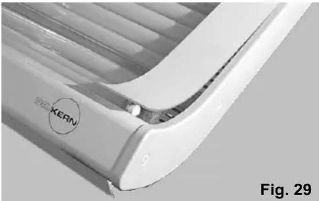
natural_image
Close-up of a white KERN air conditioner unit with visible branding and label (no text or symbols on the device itself)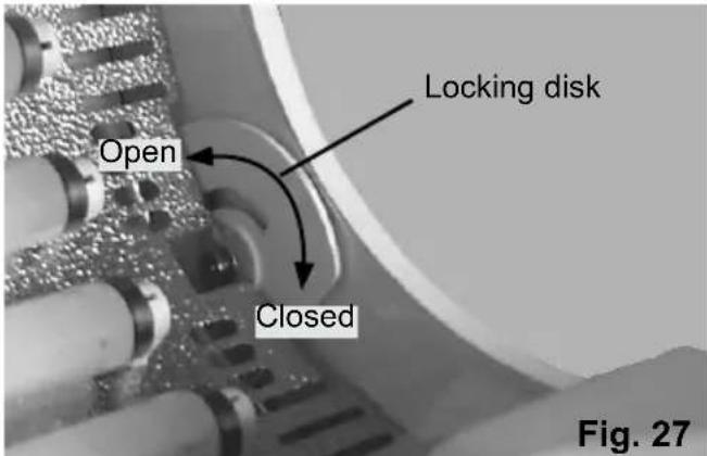
text_image
Open Closed Locking disk Fig. 27In addition the acrylic sheet is „locked“ both on the left and on the right side in the area of the back bending. Upon „unlocking“ this disk - see Fig 26 + 27 - the acrylic sheet must be pressed down and backwards in the area of the back bending and backwards in the front area (Fig. 28).
Through this shifting the acrylic sheet gets free at the longitudinal front rail and can be removed.
Notice
The acrylic glass expands when heated up and becomes longer and wider. For this reason it shall be removed only when cold.
For replacement of the sheet it is placed in the groove of the longitudinal front rail with its longitudinal front side and put down on the supports of the bench. Now push the sheet at the longitudinal back side at several places in succession slightly down, with sufficient pressure the sheet will snap into the groove of the longitudinal rail. Finally relock the acrylic sheet on the left and right side.
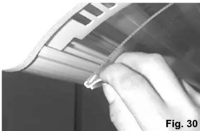
In the canopy the acrylic sheet is placed with prestress in the grooves of the longitudinal rails. To remove the sheet pull it inwards at one end of the longitudinal front rail, see Fig. 30, and remove the sheet together with the profi le cover strip of the sheet from the groove of the longitudinal front rail.
natural_image
Close-up of a hand holding a small metallic object against a metallic surface, no visible text or symbolsAfterwards remove the sheet from the groove of the longitudinal back rail.
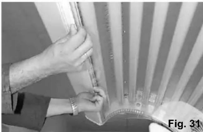
For replacement of the sheet it is placed in the groove of the longitudinal back rail with one of the sheet's longitudinal sides. To make sure that the sheet can engage in the longitudinal front rail, the sheet must now be prestressed. For this purpose push the sheet at its middle part up until the sheet engages in the groove of the longitudinal front rail.
In order to prevent possible health damage make sure to use only the original lamps (observe the specification given on the lamp label). These will be provided by your dealer.
To remove a lamp, rotate it until the contact pins become visible in the lamp holders. Pull the lamp out after that. Do not apply excessive force. The new replacement lamp shall be inserted in the similar manner – line up the contact pins with the lamp holders, press the lamp into position and rotate it to ca. 90° until it is held firmly.
Make sure to replace the corresponding starter by each lamp replacement. The starter is removed by pulling it with slight counter clockwise rotation. To insert the new starter press it into the holder and rotate clockwise until it is held firmly.
natural_image
Close-up of hands holding a fan blade with metal components, labeled 'Fig. 31' (no other text or symbols visible)Maintenance of the face-tanner
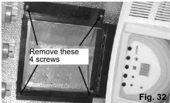
The lamp of the face-tanner must also be maintained at regular intervals. To do this, the filter cassette must be taken out by removing the 4 screws shown below in Fig. 32.
Notice The acrylic glass, originally a fl at sheet, has been installed under tension by the factory assembly. In the course of time acrylic glass takes the curved shape of the solarium and “remembers” after being removed. For this reason it must be re-inserted in exactly the same position as it was before removal.
Acrylic glass sheet shall be cleaned on both sides regularly. Use only the appropriate solvent-free non-aggressive household cleaners (suitable for acrylic).
text_image
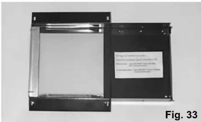
Remove these 4 screws Fig. 32The filter and lower safety plate can be removed from the cassette for cleaning, see Fig. 33.
text_image
Fig. 33 The image is not clearly visible in the image. Dialysis, reduction, and other effects of the material are shown in the image. Description: A sample was used for the material to detect the product or the material's internal structure. Dialysis, reduction, and other effects of the material are shown in the image. Dialysis, reduction, and other effects of the material are shown in the image.When refi tting the plate, always ensure that the fi Iter plate is inserted facing upward, i.e. toward the face-tanner. To ensure this is done correctly, you should mark the plate accordingly when removing it, and then refi t it in the same way.
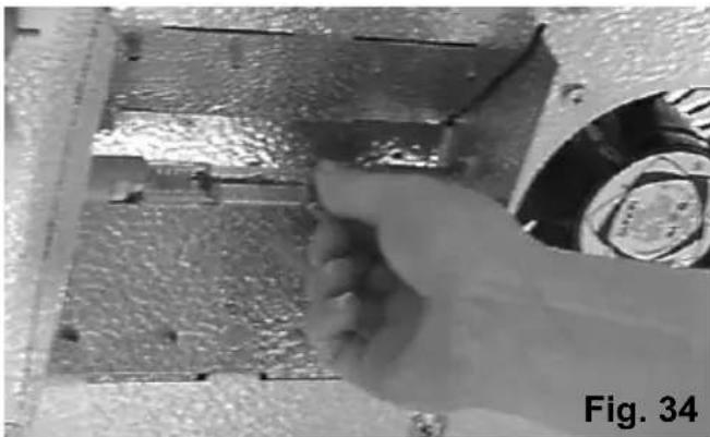
To change the metal halogen lamp, grasp the lamp at one of the flattened ends, and push approximately in the lengthwise direction in order to remove it from the holder, see Fig. 34.
natural_image
Close-up of a hand holding a tool against a metallic panel, with no visible text or symbols.The new lamp is inserted in the same way.
i Ensure that you do not touch the actual glass of the lamp. Any marks or fingerprints on the lamp should be cleaned off with pure alcohol or white spirit.
Facial lamps operate at very high temperatures and are cooled with fans in the cassettes. The lamp function is controlled additionally by a heat sensor.
Should a fan stop working in any cassette the relay will turn the unit off automatically. The face tanner may not be used until an authorised service representative has repaired the problem. Automatic emergency shut offs of this type occur rarely. The cassette fans in the facial tanners rarely fail.
Only factory - original components and spare parts may be used in servicing this solarium.
Never use a face tanner with broken or cracked filter glasses! Doing so will cause damage to eyes and facial skin.
Solarium cooling
Your solarium is equipped with the appropriate cooling system to prevent the overheating. Cool air is being sucked from the area under the bench and pressed along the lamps
The area where a user is laying on the bench usually requires the strongest cooling. Intensive air circulation will also transport dust and other impurities, which may be collected on the cooling fan and its interior parts. In the course of time this may lead to increasingly weaker air circulation and overheating of the lamps. For this reason the fans shall be inspected regularly and when necessary cleaned. Notice that the warm air (e.g. in the summer time) will not be cooling the lamps as good as the cold air. Pay attention that surrounding area has sufficient ventilation and is cool enough.
Solarium cleaning
The solarium must be completely disconnected from the power supply by all maintenance or cleaning works. By permanent connection remove the fuses to interrupt the power supply. Use a clean slightly wet cloth for cleaning purposes. Do not use aggressive cleaners.
Cleaning of the acrylic glass
The strong air circulation may eventually cause the inner glass surface to become dusty.
This may appear on certain areas or on the entire glass surface. The glass shall be removed as described above and cleaned regularly.
Use only suitable solvent-free household cleaners.
Glass surfaces may become dusty even by new solariums already short time after the first use. The reason may be the static electricity charge of the acrylic glass.
Such cleaning and maintenance works are not subject of the warranty!
Spare parts
Usable life of the UVA-low pressure lamps and the facial lamp in the face tanner will last about 500 hours.
Ensure that only genuine parts are used for replacement during all maintenance work.
The spare parts can be ordered from your service department or your authorised distributor under indication of the item number of the appliance (on the type plate).
The item codes of the lamps, acrylic glass and high-pressure facial tanners or glass fil-ters are given in the solarium passport.
Technical data
| Type 424/100 464/100 | ||
| UV lamps for canopy 4x100 W | / 20x80 W 4x100 W | |
| UV lamps for bench 18x100 W | 22x100 W | |
| Facial tanner 4x400 W 4x400 W | ||
| Length of lamps for canopy 1,76 m / 1,50 m 1,76 m / 1,50 m | ||
| Length of lamps for bench 1,76 m 1,76 m | ||
| Power rating, app. 6750 W 7300 W | ||
| Power supply 3N AC 400 V | 3N AC 400 V | |
| Mains cable | 2,5 mm ^2 | 2,5 mm ^2 |
| Fuses | 3x16 A 3x16 A | |
| Minimum ventilation rate, app. | 3200 m ^3 /h 3200 m ^3 /h | |
| Timer control | Integrated timer coin box (optional) | Integrated timer coin box (optional) |
| Dimensions LxWxH | 205x107x112 cm | 205x107x112 cm |
| Weight, app. | 270 kg | 280 kg |
Subject to technical modifications!
Coin Box - for professional use
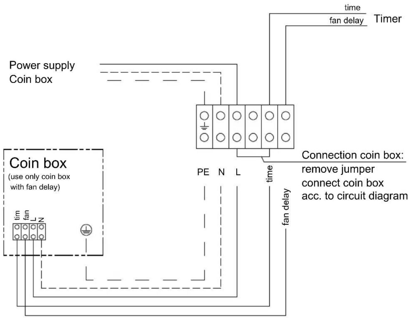
The solarium can be used with our coin box no. 95.2390 or 95.2389.
For the connection of the coin box according to the wiring diagram below, please remove the top cover of the canopy.
Pay attention to the fact that all electrical installation has to be made by an authorized expert and that the wiring diagram is only appropriate for our coin boxes. The connection of coin boxes from other suppliers may be different.
Please pay attention, that a control line for the fan delay has to be available in either case.
text_image
Power supply Coin box Coin box (use only coin box with fan delay) tim fan N time fan delay Time fan delay Timer PE N L time Connection coin box: remove jumper connect coin box acc. to circuit diagramSwitching to coin box operation
2 persons are required for this procedure.
- When the coin box is not connected yet, separate the sun bed completely from the power supply.
- While one person keeps the [up] and [down] buttons at the timer control panel simultaneously pressed, the other person shall connect the sun bed to the power supply.
- When the coin box is already connected, the sun bed must not be disconnected from the power supply.
In this case proceed as follows:
one person keeps the [up] and [down] buttons at the timer control panel simultaneously pressed.
- the other person shall start the coin box running by throwing in a coin (token).
- Keep pressing the [up] and [down] buttons until "0" appears on the timer display.
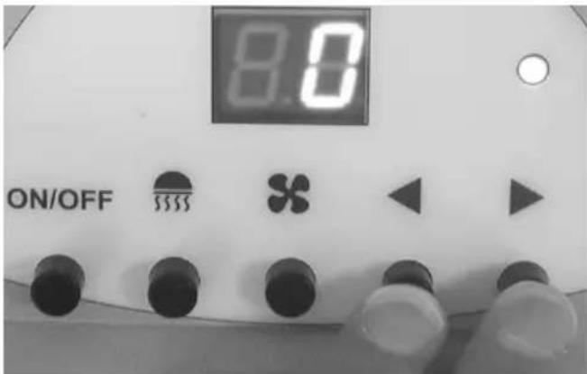
text_image
8.0 ON/OFF S$$$The sun bed is now coin box operated.
After being released by the coin box the time will start counting from "0" minutes upwards.
The sun bed can be turned on or off within this time.
The [up] and [down] buttons are locked, the other buttons remain functional.
The pre-set time has elapsed, the sun bed will be completely switched off and time display will go out.

Attention: The fan delay has to be executed by the coin box!
Returning to timer operation
Returning the sun bed back to timer operation is only possible if the coin box is completely disconnected and the jumper "L1-Time" is restored (see connection diagram).
2 persons are required for this procedure.
- Disconnect the sun bed completely from the power supply.
- While one person keeps the body fan and face tanner buttons simultaneously pressed, the other person shall connect the sun bed to the power supply again.
- Keep pressing both buttons until "88" appears on the timer display.
• The display will go out thereafter.
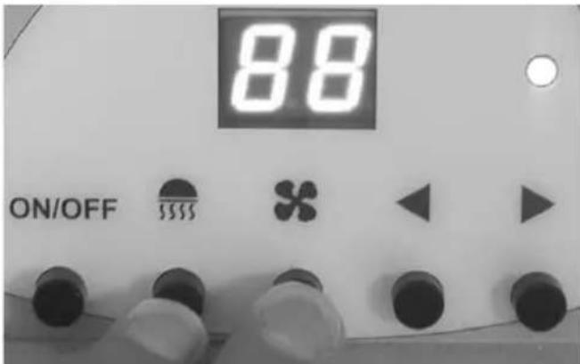
text_image
88 ON/OFF SSSSThe sun bed is now timer operated.
Timer adjustment
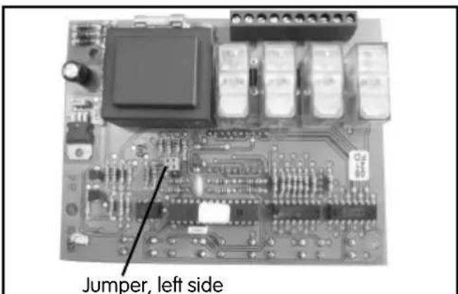
text_image
Jumper, left sideJumper, left side (fan delay)
opened = without fan delay
closed = with fan delay
Guarantee
The guarantee is taken over according to the legal regulations at present.
Manufacturer's warranty
- The period of warranty starts from the date of purchase and is in principle valid for 12 months.
- Always include the completed warranty certificate when returning equipment.
- The warranty expires for appliances which have been modified without manufacturer's explicit agreement.
- Damages caused by incorrect operation or handling through non-authorized persons are not covered under the terms of warranty.
- In the event of a claim, please indicate the serial number as well as the article code number and type name with expressive description of the fault.
- This warranty covers damaged parts but no defects due to wear and tear.
In case of complaint please return the equipment in its original packaging or other suitable packaging (caution: danger of transport damage) to our service department.
Always include the completed warranty certificate when returning equipment.
Possible shipping costs arising from the transport to and from point of repair cannot be borne by us.
Outside of Germany please contact your specialist dealer in case of warranty claims. Direct warranty processing with our service department is in this case not possible.
Service address
Kern GmbH
Please keep this address in a safe place together with the installation guide.
To help us answer your questions quickly and competently, please provide data printed on the ID plate, to include system type, article no. and serial no., in all inquiries.
Equipment start-up date:
Stamp and signature of the authorized electrician:
Handling procedures for return shipments (RMA) - Details for all returns!
Dear customer
we hope that you will rejoice in the ordered articles. Just in case that you are not entirely contented as an exception, please follow the procedures specified below. This enabling us to ensure a quick and smooth handling of the return shipment.
Please absolutely respect for all returns!
- Please add the available RMA-voucher always completely filled out together with an invoice copy to the return shipment! Do not stick it on the goods or on the packaging. We do not accept the return shipment without these papers.
- Not prepaid parcels will be refused and returned to Sender! Please always ask for the RMA-No. for the cheapest return.
- Please pay attention that the goods have to be sent back without visible marks of use in the original scope of delivery and in original packing.
- We recommend to use an additional solid and break-proof covering box which should be pad-ded out with styrofoam, paper or similar. Transport damages as a result of faulty packing are for the sender's account.
Form of complaint:
1) Transport damage
- Please check the content of your parcel immediately and advise the forwarding company of a claim (parcel service/freight forwarder)
- Do not use damaged goods!
- Ask the forwarder for a written acknowledgement of the damages.
• Report the claim promptly by phone to your dealer. He will discuss with you how to act in this case. - If the transport box has been damaged, please use an additional covering box. Do not forget to add the acknowledgement of the damage of the forwarding company!
2) Faulty goods
- The implied warranty period is 2 years. Please contact your dealer in case of faulty or wrong articles or missing accessories. He will discuss with you the individual case and try for immediate and customer-friendly solution.
- For economic returns within Germany you will get an RMA-number from the manufacturer.
- All returns have to be in the original packing of the goods with corresponding accessories. Please repack the goods to avoid damages. In case of wrong delivery, please do not use this article!
3) Problems of installation and functioning
- Please read the manual carefully first of all and pay attention to the indicated assembly or installing instructions.
- Your dealer should be the first contact person because he knows his products best and also knows possible problems.
- In case of function problems with an article, please check at first whether there is an obvious material defect. The quality system in our factory reduces malfunctions of new appliances to almost zero.