
MGKW-901 - Cooker M-SYSTEM - Free user manual and instructions
Find the device manual for free MGKW-901 M-SYSTEM in PDF.


| Product Type | Built-in gas hob |
| Brand | M-System |
| Model | MGKW-901 |
| Total Cooking Zones | 5 (4 gas burners + 1 triple-ring burner) |
| Burner Types and Power | Auxiliary 1.00 kW, Semi-rapid 1.75 kW (x2), Rapid 3.00 kW, Triple-ring 3.30 kW |
| Gas Type | Natural gas (G20) or LPG (G30/G31), convertible |
| Ignition | Electric spark ignition |
| Safety Device | Flame failure safety valve on each burner |
| Power Supply | 230 V AC, 50 Hz |
| Cut-out Dimensions (W x D) | 470 x 550 mm |
| Overall Dimensions (W x D) | Approx. 580 x 500 mm |
| Material | Stainless steel and enamel |
| Pan Supports | Enamelled steel grids |
| Compatible Pan Diameters | Auxiliary: 6–14 cm, Semi-rapid: 16–20 cm, Rapid: 20–24 cm, Triple-ring: 24–28 cm |
| Gas Connection | 1/2" G thread (cylindrical or conical), flexible hose |
| Electrical Cable | 3 x 0.75 mm², type HO5V2V2-F, 90°C rated |
| Ignition Power Consumption | Negligible (spark only) |
| Installation Clearances | Min. 100 mm side walls, 650 mm above, 30 mm below |
| Cleaning Instructions | Use soapy water or non-abrasive detergents; avoid acidic substances |
| Included Accessories | Installation brackets, sealing material, injectors for gas conversion |
| Energy Source | Gas |
Frequently Asked Questions - MGKW-901 M-SYSTEM
User questions about MGKW-901 M-SYSTEM
0 question about this device. Answer the ones you know or ask your own.
Ask a new question about this device
Download the instructions for your Cooker in PDF format for free! Find your manual MGKW-901 - M-SYSTEM and take your electronic device back in hand. On this page are published all the documents necessary for the use of your device. MGKW-901 by M-SYSTEM.
USER MANUAL MGKW-901 M-SYSTEM
BUILT-IN COOKING HOBS
Instruction for the use Installation advice
English Page Instruction for the use - Installation advice
Geachte Klant,
natural_image
Diagram showing a hand holding a bag with arrows indicating motion, and scattered particles below (no text or symbols)Ontsteking van branders MET ELEKTRISCHE ONSTEKING
natural_image
Line drawing of a cooking pot on a stove (no text or symbols)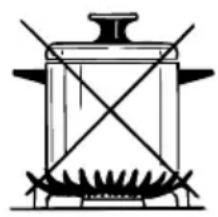
natural_image
Simple line drawing of a cooking pot with stirrer (no text or symbols)afb. 2.4
ALGEMENE RAAD
natural_image
Mechanical assembly diagram showing a rotating component with a curved arrow indicating motion, labeled 'afb. 3.2' (no text or symbols on the diagram itself)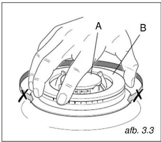
BRANDER MET DRIEDUBBELE KRANS
natural_image
Technical line drawing of a mechanical component with a cross mark indicating a crossed section (no text or symbols present)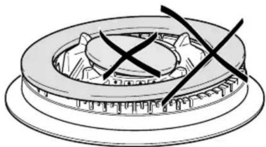
natural_image
Technical line drawing of a mechanical component with cross marks indicating assembly or inspection (no text or symbols)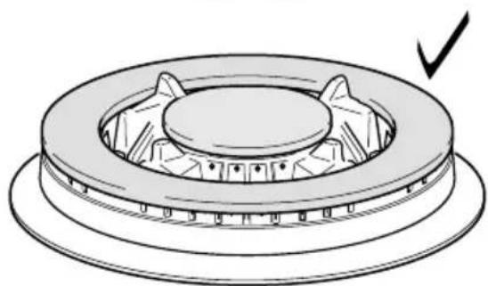
natural_image
Technical line drawing of a mechanical component with a circular base and central hub, showing a checkmark indicating a detail (no text or symbols present)afb. 3.4
natural_image
Diagram of a mechanical assembly showing a top-down view of a gear-like component with a central gear and a bottom view of a hexagonal base (no text or symbols)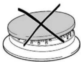
natural_image
Simple line drawing of a layered cake with a cross mark on top (no text or symbols)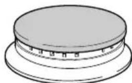
natural_image
Simple line drawing of a circular object with a flat top and base, no text or symbols present.afb. 3.5
natural_image
Illustration of a hand using a wrench to adjust a pipe fitting on a metal shelf (no text or symbols)VERVANGING SPROEIERS VAN DE BRANDERS
natural_image
Technical line drawing of a screwdriver with a base mount, no text or symbols present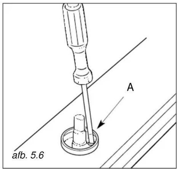
natural_image
Line drawing of a cooking pot on a stove (no text or symbols)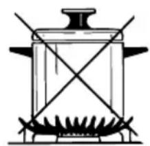
natural_image
Simple line drawing of a cooking pot with two crossed panes (no text or symbols)Abb. 2.4
natural_image
Mechanical assembly diagram showing a rotating disk with a curved arrow indicating motion, labeled 'Abb. 3.2' (no text or symbols on the diagram itself)
DREIKRANZBRENNER
natural_image
Cross-sectional diagram of a mechanical component with no visible text or symbols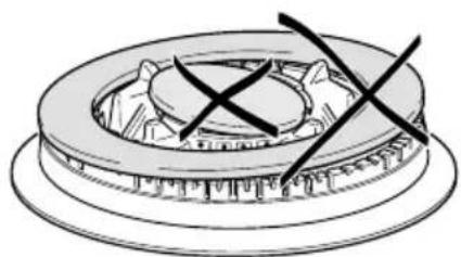
natural_image
Mechanical component diagram showing a gear and shaft assembly with no visible text or symbols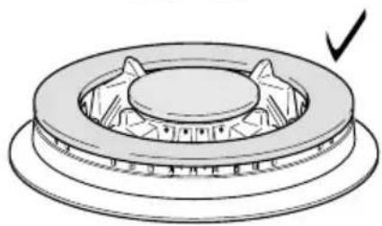
natural_image
Technical line drawing of a mechanical component with a circular base and central gear (no text or symbols)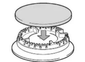
natural_image
Diagram of a mechanical component with a downward arrow indicating rotation or force (no text or symbols)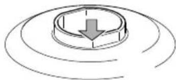
natural_image
Diagram of a circular object with a downward arrow, surrounded by concentric curved lines (no text or symbols)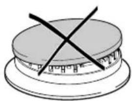
natural_image
Simple line drawing of a layered cake with a cross mark on top (no text or symbols)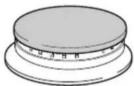
natural_image
Simple line drawing of a circular object with horizontal markings, resembling a mechanical or architectural component (no text or symbols)Abb. 3.4
Abb. 3.5
natural_image
Line drawing of a hand using a wrench to adjust a component on a metal shelf (no text or symbols)AUSTAUSCH DER DÜSEN
natural_image
Technical line drawing of a screwdriver with a base mount, mounted on a diagonal surface (no text or symbols)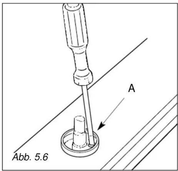
natural_image
Diagram showing a circular object with internal lines and droplet symbols, labeled Fig. 2.1 (no text or labels on the diagram itself)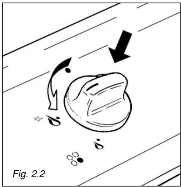
natural_image
Diagram showing a hand holding a bag with arrows indicating motion, and scattered particles below (no text or symbols)Quemadores de gas CON ENCENDIDO ELÉCTRICO
natural_image
Line drawing of a cooking pot on a stove (no text or symbols)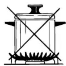
natural_image
Simple line drawing of a cooking pot with crossed panes and a side dish (no text or symbols)Fig. 2.4
CONSEJOS GENERALES
natural_image
Mechanical assembly diagram showing a rotating component with a curved arrow indicating motion, labeled 'Fig. 3.2' (no text or symbols on the diagram itself)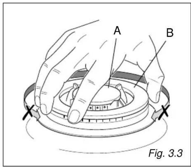
natural_image
Technical line drawing of a mechanical component with a cross mark indicating no text or symbols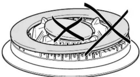
natural_image
Technical line drawing of a mechanical component with two crossed X marks (no text or symbols)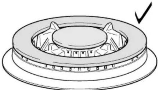
natural_image
Technical line drawing of a mechanical component with a circular base and central hub, showing internal gear-like structure (no text or symbols)Fig. 3.4
natural_image
Diagram of a mechanical assembly showing a top-down view of a gear-like component with a central gear and a base component (no text or symbols)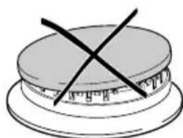
natural_image
Simple line drawing of a layered cake with a cross mark on top (no text or symbols)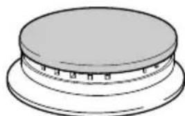
natural_image
Simple line drawing of a circular object with a flat top and base, no text or symbols present.Fig. 3.5
natural_image
Illustration of a hand using a wrench to adjust a component on a metal shelf (no text or symbols)natural_image
Technical line drawing of a mechanical component with labeled part 'J' and directional arrow, no readable text or symbols beyond labelES
TABLA DE INYECTORES - Cat: II 2H 3+
| QUEMADOR | PORTADA NOMINAL [kW] | PORTADA REDUC. [kW] | G30/G31 G 2028-30/37 mbar 20 mbar | |||
| By-pass [1/100 mm] | ∅ inyectores [1/100 mm] | By-pass [1/100 mm] | ∅ inyectores [1/100 mm] | |||
| Auxiliair (A) | 1,00 | 0,30 | 27 | 50 | Regulable | 72 |
| Semirrápido (SR) | 1,75 | 0,45 | 34 | 65 | Regulable | 97 |
| Rápido (R) | 3,00 | 0,75 | 44 | 85 | Regulable | 115 |
| Superquemador (TC) | 3,30 | 1,50 | 65 | 91 | Regulable | 124 |
| APORTE DE AIRE NECESARIO PARA LA COMBUSTIÓN DEL GAS (2 m3/h x kW) | |
| QUEMADOR | Benodigde luchttoevoer [m3/hr] |
| Auxiliair (A) | 2,00 |
| Semirrápido (SR) | 3,50 |
| Rápido (R) | 6,00 |
| Superquemador (TC) | 6,60 |
natural_image
Technical line drawing of a screwdriver with a base mount, labeled Fig. 5.5 (no text or symbols on the diagram itself)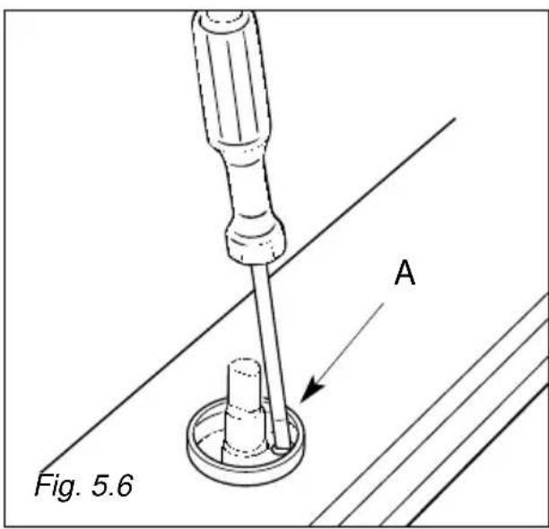
Thank you for having purchased and given your preference to our product.
The safety precautions and recommendations given below are for your own safety and that of others. They will also provide a means by which to make full use of the features offered by your appliance.
Please keep this booklet carefully. It may be useful in future, either to yourself or to others if doubts should arise relating to its operation.
This appliance must be used only for the task it has explicitly been designed for, that is for cooking foodstuffs. Any other form of usage is to be considered as inappropriate and therefore dangerous.
The manufacturer declines all responsibility in the event of damage caused by improper, incorrect or unreasonable use of the appliance.
IMPORTANT PRECAUTIONS AND RECOMMENDATIONS FOR USE OF ELECTRICAL APPLIANCES
Use of any electrical appliance implies the necessity to follow a series of fundamental rules. In particular:
√ Never touch the appliance with wet hands or feet;
√ do not operate the appliance barefooted;
√ do not allow children or disabled people to use the appliance without your supervision.
The manufacturer cannot be held responsible for any damages caused by improper, incorrect or unreasonable use of the appliance.
IMPORTANT PRECAUTIONS AND RECOMMENDATIONS
√ After having unpacked the appliance, check to ensure that it is not damaged. If you have any doubts, do not use it and consult your supplier or a professionally qualified technician.
√ Packing elements (i.e. plastic bags, polystyrene foam, nails, packing straps, etc.) should not be left around within easy reach of children, as these may cause serious injuries.
√ The packaging material is recyclable and is marked with the recycling symbol ⬆.
√ Do not attempt to modify the technical characteristics of the appliance as this may become dangerous to use.
√ The manufacturer cannot be considered responsible for damage caused by unreasonable, incorrect or rash use of the appliance.
√ If you should decide not to use this appliance any longer (or decide to substitute an older model), before disposing of it, it is recommended that it be made inoperative in an appropriate manner in accordance to health and environmental protection regulations, ensuring in particular that all potentially hazardous parts be made harmless, especially in relation to children who could play with old appliances.
√ The appliance should be installed and all the gas/electrical connections made by a qualified engineer in compliance with local regulations in force and following the manufacturer's instructions
TIPS FOR THE USER
√ During and after use of the cooktop, certain parts will become very hot. Do not touch hot parts.
√ Keep children away from the cooking hob when it is in use.
√ After use, ensure that the knobs are in position • (off), and close the main gas delivery valve or the gas cylinder valve.
√ In case of difficulty in the gas taps operation, call Service.
√ Before any cleaning or maintenance, switch off the electricity to the cooktop.
Risk of fire!
√ Do not leave inflammable material on the cooktop.
√ Make sure that the electrical cables of other appliances installed nearby cannot come into contact with the cooktop.
DESCRIPTION OF BURNERS
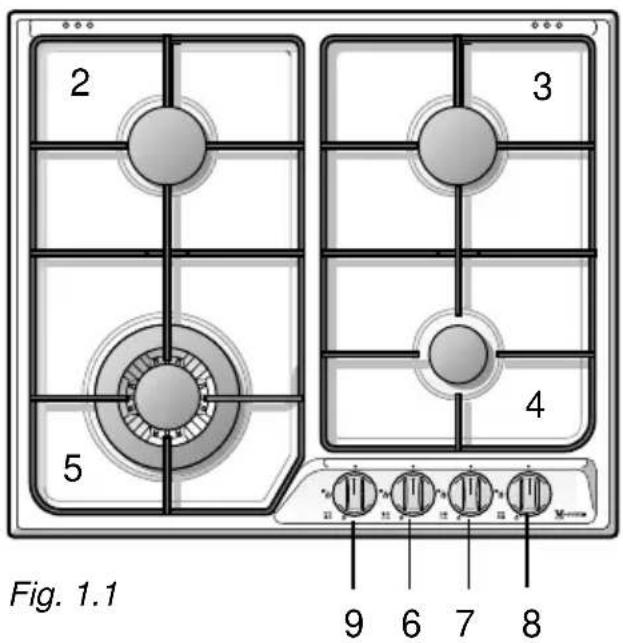
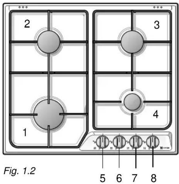
- Rapid burner (R1) - 3,00 kW
- Semirapid burner (SR) - 1,75 kW
- Semirapid burner (SR) - 1,75 kW
- Auxiliary burner (A) - 1,00 kW
- Triple-ring burner (TR) - 3,30 kW
CONTROL PANEL DESCRIPTION
- Front left rapid burner 1 (R1) control knob
- Rear left semirapid burner 2 (SR) control knob
- Rear right semirapid burner 3 (SR) control knob
- Front right auxiliary burner 4 (A) control knob
- Triple-ring burner 5 (TR) control knob
GAS BURNERS
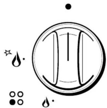
Gas flow to the burners is adjusted by turning the knobs illustrated in fig. 2.1 which control the safety valves.
Turning the knob so that the indicator line points to the symbols printed on the panel achieves the following functions:
- full circle = closed valve
- symbol = maximum
aperture or flow
- symbol = minimum
aperture or flow
√ To light one of the gas burners, hold a flame (e.g. a match) close to the top part of the burner, push in and turn the relative knob in an anti-clockwise direction, pointing the knob indicator towards the large flame symbol (i.e. max. gas flow).
√ To reduce the gas flow to minimum, rotate the knob further anti-clockwise to point the indicator towards the small flame symbol.
√ The maximum aperture position permits rapid boiling of liquids, whereas the minimum aperture position allows slower warming of food or maintaining boiling conditions of liquids.
√ Other intermediate operating adjustments can be achieved by positioning the indicator between the maximum and minimum aperture positions, and never between the maximum aperture and closed positions.
natural_image
Symbolic diagram with a circular shape containing vertical lines and droplet-like shapes below, no readable text or labels.Fig. 2.1

natural_image
Diagram showing a hand holding a small object with arrows indicating motion, labeled 'Fig. 2.2' (no text or symbols on the diagram itself)Lighting the burners WITH ELECTRIC IGNITION
To light one of the burners, press and turn the corresponding knob to the maximum flow position (large flame) and keep the knob pressed down until the gas is lit (fig. 2.2).
Turn the gas tap to the position required. Whenever special conditions of the gas supplied locally make it difficult to light the burner with the knob in the maximum flow position, repeat the operation with the knob in the minimum flow position.
Caution! the cooking hob becomes very hot during operation. Keep children well out of reach.
GRILL FOR SMALL COOKWARE (fig. 2.3)
Put it on the auxiliary burner (the smallest) grid when small cookware is being used to prevent the cookware from tipping over.
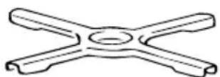
Fig. 2.3
CHOICE OF BURNER
On the control panel, near every knob, there is a diagram that indicates which burner is controlled by that knob.
The suitable burner must be chosen according to the diameter and the capacity used.
As an indication, the burners and the pots must be used in the following way:
| DIAMETERS OF PANS WHICH MAY BE USEDON THE HOBS |
| BURNERS MINIMUM MAX. |
| Auxiliary 6 cm 14 cm |
| Semirapid 16 cm 20 cm |
| Rapid 20 cm 24 cm |
| Triple-ring 24 cm 28 cm |
| Maximum diameter for woks: 36 cm. |
| do not use pans with concave or convex bases |
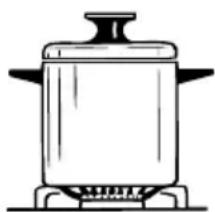
It is important that the diameter of the pots or pans suitably match the heating potential of the burners in order not to jeopardise the efficiency of the burners, bringing about a waste of gas fuel.
A small diameter pot or pan placed on a large burner does not necessarily mean that boiling conditions are reached quicker.
Only used flat bottomed pans.
natural_image
Line drawing of a cooking pot on a stove (no text or symbols)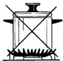
natural_image
Simple line drawing of a cooking pot with crossed panes (no text or symbols)Fig. 2.4
GENERAL ADVICE
√ Before you begin cleaning you must ensure that the hob is switched off. It is advisable to clean when the appliance is cold and especially when cleaning the enamelled parts.
√ All enamelled surfaces have to be washed with soapy water or some other non-abrasive product with a sponge and are to be dried preferably with a soft cloth.
√ Avoid leaving alkaline or acid substances (lemon juice, vinegar etc.) on the surfaces.
ENAMELLED PARTS
√ All the enamelled parts must be cleaned with a sponge and soapy water only or other non-abrasive products.
√ Dry preferably with a chamois leather. If acid substances such as lemon juice, tomato conserve, vinegar etc. are left on the enamel for a long time they will etch it, making it opaque.
STAINLESS STEEL ELEMENTS
√ Stainless steel parts must be rinsed with water and dried with a soft and clean cloth or with a chamois leather.
√ For persistent dirt, use specific non-abrasive products available commercially or a little hot vinegar.
√ Note: regular use could cause discolouring around the burners, because of the high flame temperature.
COOKING HOB WITH GLASS LID (optional)
√ Do not close the glass lid when the gas burner or electrical plates are still hot and when the oven, installed below the cooking hob, is on or still hot.
√ Do not rest hot pans or heavy objects on the cooker lid.
√ Remove any spillages from the surface of the lid before opening.
CONTROL KNOB
√ The control knobs may be removed for cleaning but care should be taken not to damage the seal.
GAS TAPS
√ Periodic lubrication of the gas taps must be carried out by specialist personnel only.
√ In the event of operating faults in the gas taps, call the Service Department.
BURNERS AND GRIDS
√ These parts can be removed and cleaned with appropriate products.
√ After cleaning, the burners and their flame spreaders must be well dried and correctly replaced.
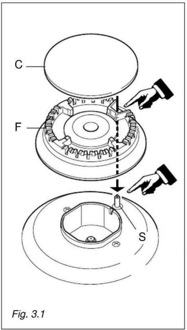
√ It is very important to check that the burner flame spreader and the cap have been correctly positioned. Failure to do so can cause serious problems.
√ In appliances with electric ignition keep the electrode clean so that the sparks always strike.
√ Note: To avoid damage to the electric ignition do not use it when the burners are not in place.
CORRECT REPLACEMENT OF THE BURNERS
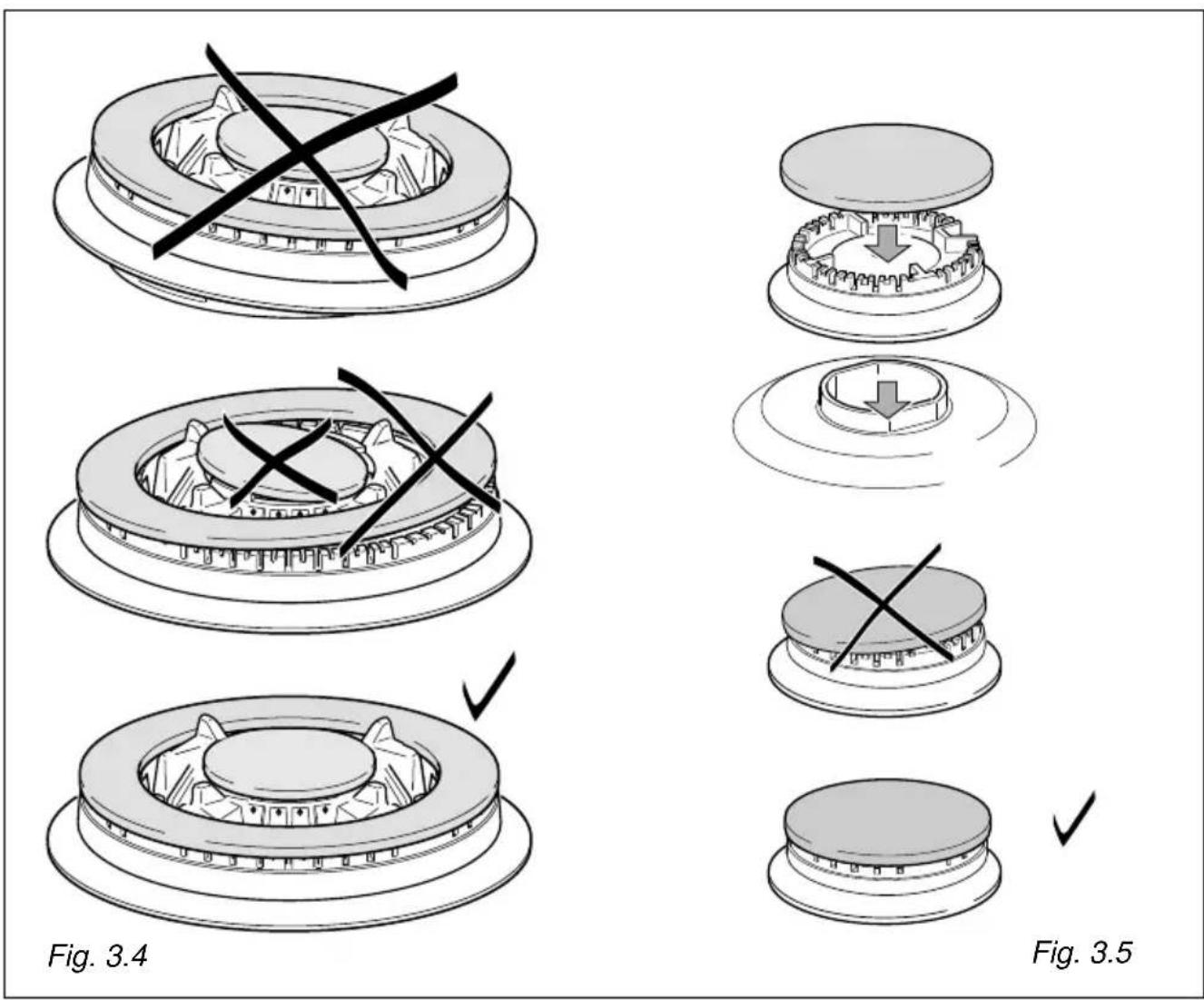
It is very important to check that the burner flame spreader F and the cap C have been correctly positioned (see figs. 3.1 and 3.5). Failure to do so can cause serious problems. Check that the electrode "S" (fig. 3.1) is always clean to ensure trouble-free sparking. Both the probe and ignition plug must be very carefully cleaned.
natural_image
Mechanical assembly diagram showing a rotating wheel and gear mechanism (no text or symbols)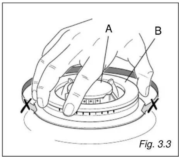
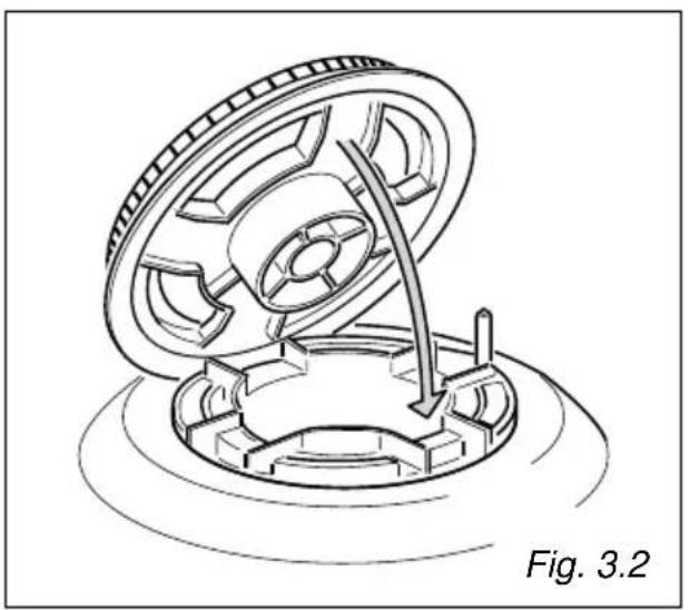
CORRECT POSITION OF TRIPLE RING BURNER
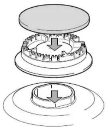
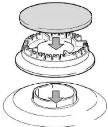
The triple ring burner must be correctly positioned (see fig. 3.2); the burner rib must be fitted in their housing as shown by the arrow.
Then position the cap A and the ring B (fig. 3.3 - 3.4).
The burner correctly positioned must not rotate (fig. 3.3).
Installation advice
4
INSTALLATION
IMPORTANT
√ The appliance should be installed, regulated and adapted to function with other types of gas by a QUALIFIED INSTALLATION TECHNICIAN.
√ The appliance must be installed in compliance with regulations in force in your country and in observation of the manufacturer's instructions.
√ Always unplug the appliance before carrying out any maintenance operations or repairs.
√ The appliance must be housed in heat-resistant units.
√ These tops are designed to be embedded into kitchen fixtures measuring 600 mm in depth.
√ The walls of the units must not be higher than work top and must be capable of resisting temperatures of 75 °C above room temperature.
√ Do not install the appliance near inflammable materials (eg. curtains).
In order to install the cooker top into the kitchen fixture, a hole with the dimensions shown in fig. 4.1 has to be made, bearing in mind the following:
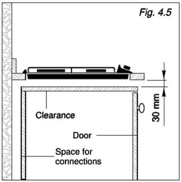
√ within the fixture, between the bottom side of the cooker top and the upper surface of any other appliance or internal shelf there must be a clearance of at least 30 mm;
√ the cooker top must be kept no less than 100 mm away from any side wall (fig. 4.1).
√ the hob must be installed at least 35 mm from the wall.
√ there must be a distance of at least 650 mm between the hob and any wall cupboard or extractor hood positioned immediately above (see fig. 4.2)
√ It is absolutely essential that you place a separator between the base of the hob and the drawer unit.
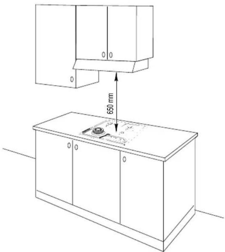
Fig. 4.2
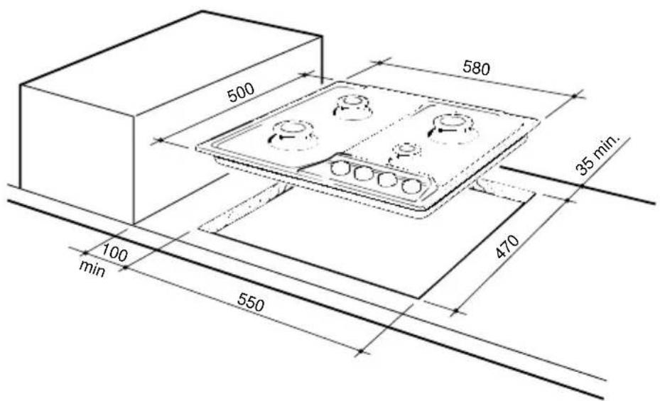
Fig. 4.1
In the room chosen to accommodate the gas appliance, there must be an adequate natural draft to allow combustion of the gas.
The flow of air must come directly from one or more openings made in the outside walls with a free area of at least 200 cm ^4 .
The vents must be positioned close to the floor, preferably on the opposite side to the combustion discharge outlet and must be designed in such a way that they cannot be obstructed either from the inside or the outside.
When it is not possible to provide the necessary vents, the draft may be supplied from an adjacent room, ventilated in the required manner, provided it is not a bedroom or an area at risk.
In this event, the door of the kitchen must be opened to allow the draft to enter the room.
DISCHARGING PRODUCTS OF COMBUSTION
Extractor hoods connected directly to the outside must be provided, to allow the products of combustion of the gas appliance to be discharged (fig. 4.3).
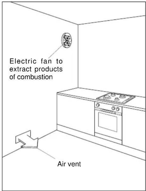
If this is not possible, an electric fan may be used, attached to the external wall or the window; the fan should have a capacity to circulate air at an hourly rate of 3-5 times the total volume of the kitchen (fig. 4.4).
The fan can only be installed if the room has suitable vents to allow air to enter, as described under the heading "Choosing suitable surroundings".
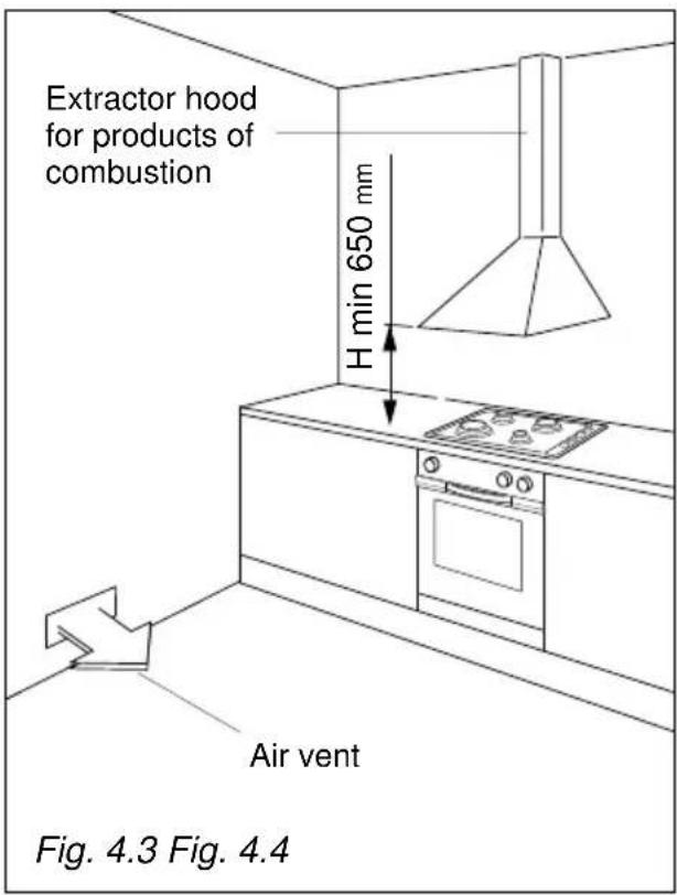
INSTALLATION IN KITCHEN CABINET WITH DOOR (fig. 4.5)
The fixture has to be made according to specific requirements in order to prevent the gas burners from going out, even when the flame is turned down to minimum, due to pressure changes while opening or closing the cupboard doors.
It is recommended that a 30 mm clearance be left between the cooker top and the fixture surface (fig. 4.5).
FASTENING THE INSTALLATION BRACKETS (fig. 4.6)
Each cooker top is provided with an installation kit including brackets and screws for fastening the top to fixture panels from 2 to 4 cm thick.
Turn the cooker top upside down and fasten the brackets "A" to the appropriate socket holes, without tightening the screws "B" for the moment. Make sure that the brackets are fastened as shown in figure 4.6.
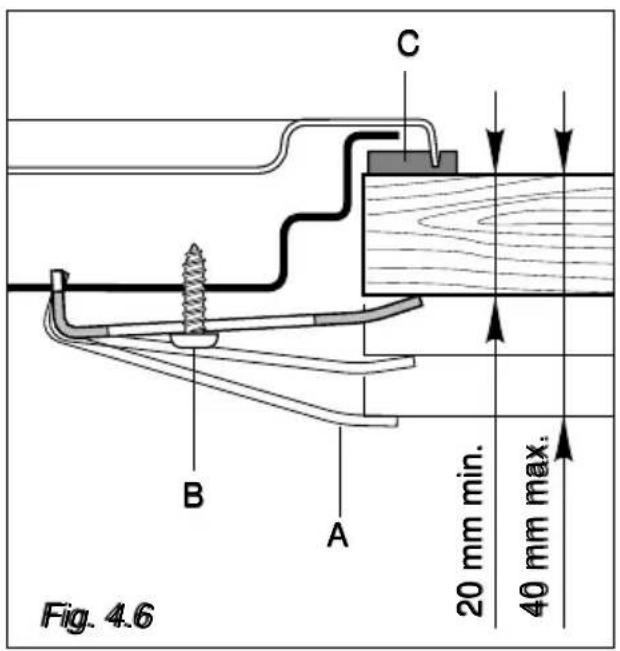
FASTENING THE COOKER TOP (fig. 4.6)
- Spread the sealing material "C" out along the fixture hole, making sure that the junctions overlap at the corners.
- Insert the cooker top into the hole and position it correctly.
- Adjust the position of the brackets "A" and tighten screws "B" to block the cooker top firmly in position.
- With a sharp cutter or trimmer knife trim the excess sealing material around the edge of the cooker top.
Cat: II 2L 3B/P

Cat: II 2H3+
GAS CONNECTION
The cooktop is set up and calibrated to work with the gas indicated on the rating plate affixed to the appliance and on this instruction booklet.
The gas supply system must conform to the local regulations in force.
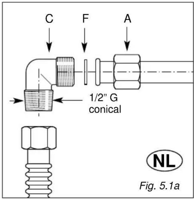
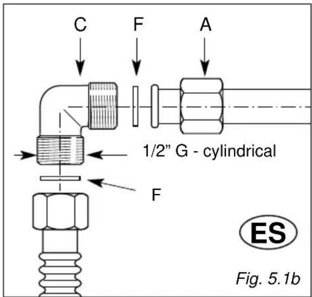
To conned the cooktop to the gas mains or cylinder use a flexible stainless steel hose with continuous wall conforming to local regulations. Use gasket F for the cylindrical elbow connection.
The flexible metal tubes must be at most 2 m long.
Attention: If a flexible stainless steel hose is used, it must be so installed that it cannot come into contact with a movable part of the unit and is not obstructed and so that its whole length can be inspected.
The cooktop connection is made up as follows:
√ 1 nut "A"
√ union elbow "C":
- cylindrical - for Spain
- conical - for Holland
√ gaskets "F"
IMPORTANT
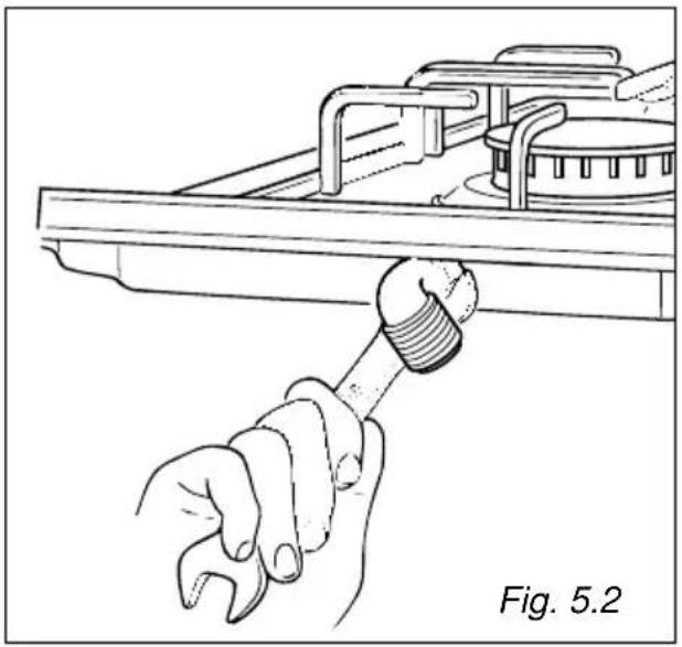
√ Never attempt to turn the fitting C without having first slackened off the relative lock nut (fig. 5.2).
√ The seal F (fig. 5.1) is the element that guarantees the seal in the pipe-ramp connector.
It is recommended that it be replaced whenever it shows even the slightest deformation or imperfection.
√ After connecting to the mains, check that the couplings are correctly sealed, using soapy solution, but never a naked flame.
natural_image
Illustration of a hand using a wrench to adjust or install a mechanical component (no text or symbols present)ADAPTING THE APPLIANCE TO FUNCTION WITH DIFFERENT TYPES OF GAS
If a different gas from that one indicated on the label is used, you need to adapt the cooktop to this new situation.
If the injectors are not supplied they can be obtained from the "Service Centre".
Select the injectors to be replaced according to the table on next page.
The nozzle diameters, expressed in hundredths of a millimetre, are marked on the body of each injector.
OPERATIONS TO BE PER- FORMED WHEN SUBSTITUT- ING THE INJECTORS
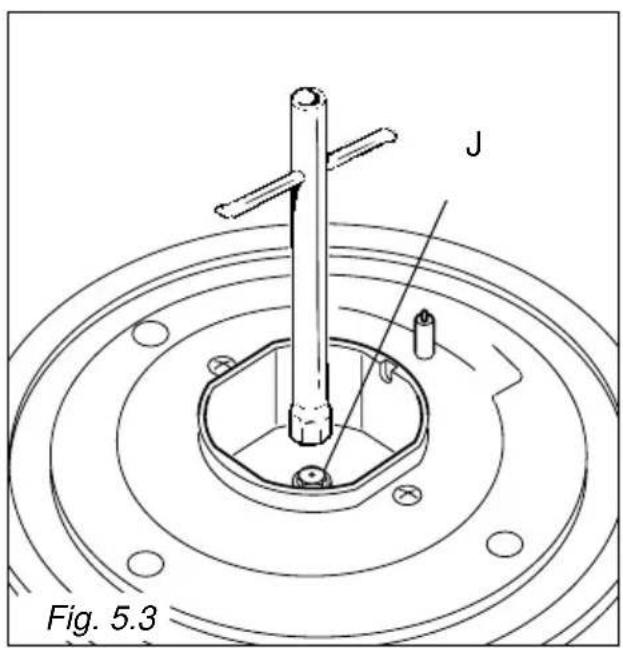
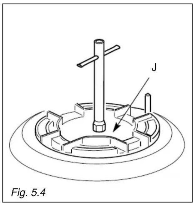
√ Remove the pan-supports, the burner covers and the knobs;
√ Using a wrench substitute the injectors "J" (Fig. 5.3 - 5.4) with those ones suitable for the type of gas for which it is to be used.
The burners are conceived in such a way so as not to require the adjustment of the primary air.
natural_image
Technical line drawing of a mechanical component with labeled part 'J' and reference to Fig. 5.4 (no text or symbols on the diagram itself)| BURNERS | Nominal power [kW] | Reduced power [kW] | G30/G31 G 25 28-30/30 mbar 25 mbar | |||
| By-pass [1/100 mm] | ∅ injector [1/100 mm] | By-pass [1/100 mm] | ∅ injector [1/100 mm] | |||
| Auxiliary (A) | 1,00 0,3 | 0 27 50 72 | Adjustable | |||
| Semirapid (SR) | 1,75 0,4 | 5 34 65 94 | ||||
| Rapid (R) | 3,00 0,7 | 5 44 85 121 | ||||
| Triple-ring (TR) | 3,30 1,5 | 0 65 91 130 | ||||
ES
TABLE FOR THE CHOICE OF THE INJECTORS - Cat: II 2H 3+
| BURNERS | Nominal power [kW] | Reduced power [kW] | G30/G31 G 2028-30/37 mbar 20 mbar | |||
| By-pass [1/100 mm] | ∅ injector [1/100 mm] | By-pass [1/100 mm] | ∅ injector [1/100 mm] | |||
| Auxiliary (A) | 1,00 | 0,30 | 27 | 50 | Adjustable | 72 |
| Semirapid (SR) | 1,75 | 0,45 | 34 | 65 | Adjustable | 97 |
| Rapid (R) | 3,00 | 0,75 | 44 | 85 | Adjustable | 115 |
| Triple-ring (TR) | 3,30 | 1,50 | 65 | 91 | Adjustable | 124 |
| AIR VENT NECESSARY FOR GAS COMBUSTION = (2 m3/hxkW) | |
| BURNERS Air vent necessary [m 3/hr] | |
| Auxiliary (A) 2,00 | |
| Semirapid (SR) 3,50 | |
| Rapid (R) 6,00 | |
| Triple-ring (TR) 6,60 | |
REGULATING THE BURNER MINIMUM SETTING
When switching from one type of gas to another, the minimum flow rate must also be correct: the flame should not go out even when passing suddenly from maximum to minimum flame.
To regulate the flame follow the instructions below:
– Light the burner
- Set the cock valve to minimum
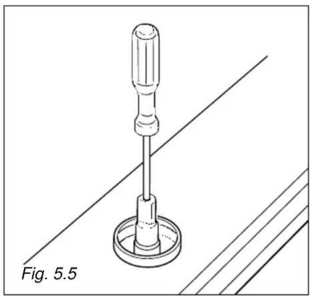
On gas valves provided with adjustment screw in the centre of the shaft (fig. 5.5):
- Using a screwdriver with max. diameter 3 mm, turn the screw inside the tap until the correct setting is obtained.
On gas valves provided with adjustment screw on the valve body (fig. 5.6):
- Turn the screw "A" to the correct setting with a screwdriver.
For G 30/G 31 gas, tighten the adjustment screw completely.
LUBRICATING THE GAS TAPS
If one of the gas taps becomes hard to turn, dismantle it, thoroughly clean with petrol and apply special high-temperature grease.
Warning!
These operations must be performed by a specialised engineer.
natural_image
Technical line drawing of a screwdriver with a base mount, labeled Fig. 5.5 (no text or symbols on the diagram itself)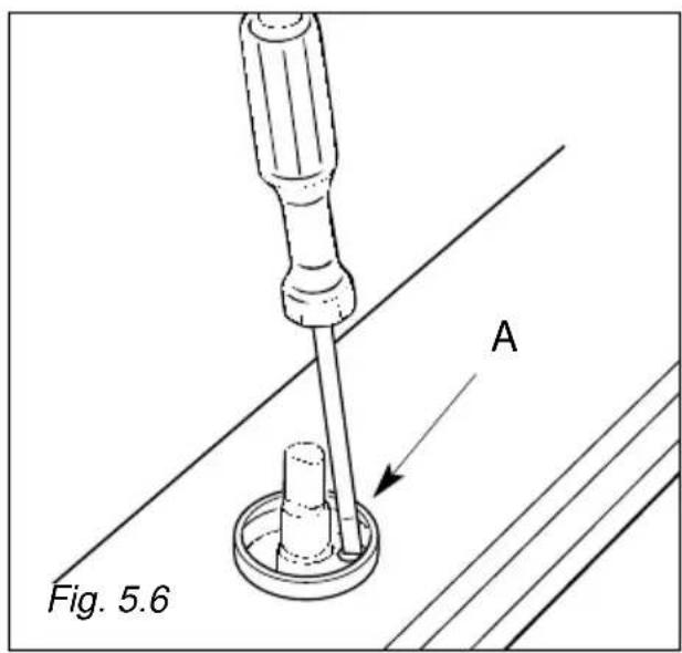
IMPORTANT:
Installation has to be carried out according to the instructions provided by the manufacturer.
Incorrect installation might cause harm and damage to people, animals or objects, for which the manufacturer accepts no responsibility.
DETAILS
√ Connection to the electric power supply must be carried out by a qualified technician and following the appropriate safety regulations;
√ Before carrying out the connection to the power supply, the voltage rating of the appliance (stamped on the appliance identification plate) must be checked for correspondence to the available mains supply voltage, and the mains electric wiring should be capable of handling the hob's power rating (also indicated on the identification plate);
√ The power point must be connected to a suitable earth wiring, in conformity to current safety regulations.
√ The hob is supplied without a power supply plug and therefore if you are not connecting directly to the mains, a standardized plug suitable for the load must be fitted.
√ It is possible to connect the appliance directly to the mains supply by means of a heavy duty switch with 3 mm minimum distance between the contacts.
√ The power supply cord must not touch against any hot surfaces and must be placed so that its temperature does not exceed 75^ C at any point along its length.
√ After having installed the appliance, the power switch or power plug must always be in a accessible position.
N.B. For connections to the mains power supply, never use adapters, reductions or multiple power points as these may overheat and catch fire.
In the event that installation should require modifications to the mains supply wiring system or if the power plug is not suitable for the type of power point available, it is recommended that a qualified technician be called to carry out substitution.
The technician will also have to verify that the cross-section of the electric cables on the power point match the appliance's power rating.
Before carrying out any work on the electrical section of the appliance, it must be disconnected from the mains.
If the power supply cable is damaged it must be substituted by a suitable cable available in the after sales service.
Connection to a good earth wiring system is absolutely essential.
The manufacturer accepts no responsibility for any inconvenience caused by failure to comply with this rule.
REPLACING THE POWER SUPPLY CABLE
Use the same type of power supply cable.
This cable must be connected to the terminal block following the diagram in fig. 6.1.
FEEDER SPECIAL CABLE SECTION Type "HO5V2V2-F" resistance to temperatures of 90°C
230 VAC 50 Hz 3 x 0,75 mm 2
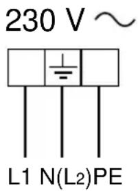
Fig. 6.1
Descriptions and illustrations in this booklet are given as simply indicative. The manufacturer reserves the right, considering the characteristics of the models described here, at any time and without notice, to make eventual necessary modifications for their construction or for commercial needs.
M-SYSTEM
1102135
- BUILT-IN COOKING HOBS
- Geachte Klant,
- Ontsteking van branders MET ELEKTRISCHE ONSTEKING
- ALGEMENE RAAD
- BRANDER MET DRIEDUBBELE KRANS
- VERVANGING SPROEIERS VAN DE BRANDERS
- DREIKRANZBRENNER
- AUSTAUSCH DER DÜSEN
- Quemadores de gas CON ENCENDIDO ELÉCTRICO
- CONSEJOS GENERALES
- ES
- TABLA DE INYECTORES - Cat: II 2H 3+
- IMPORTANT PRECAUTIONS AND RECOMMENDATIONS FOR USE OF ELECTRICAL APPLIANCES
- IMPORTANT PRECAUTIONS AND RECOMMENDATIONS
- TIPS FOR THE USER
- Risk of fire!
- DESCRIPTION OF BURNERS
- CONTROL PANEL DESCRIPTION
- GAS BURNERS
- Lighting the burners WITH ELECTRIC IGNITION
- GRILL FOR SMALL COOKWARE (fig. 2.3)
- CHOICE OF BURNER
- GENERAL ADVICE
- ENAMELLED PARTS
- STAINLESS STEEL ELEMENTS
- COOKING HOB WITH GLASS LID (optional)
- CONTROL KNOB
- GAS TAPS
- BURNERS AND GRIDS
- CORRECT REPLACEMENT OF THE BURNERS
- CORRECT POSITION OF TRIPLE RING BURNER
- Installation advice
- 4
- INSTALLATION
- IMPORTANT
- DISCHARGING PRODUCTS OF COMBUSTION
- INSTALLATION IN KITCHEN CABINET WITH DOOR (fig. 4.5)
- FASTENING THE INSTALLATION BRACKETS (fig. 4.6)
- FASTENING THE COOKER TOP (fig. 4.6)
- GAS CONNECTION
- The gas supply system must conform to the local regulations in force.
- ADAPTING THE APPLIANCE TO FUNCTION WITH DIFFERENT TYPES OF GAS
- If the injectors are not supplied they can be obtained from the "Service Centre".
- OPERATIONS TO BE PER- FORMED WHEN SUBSTITUT- ING THE INJECTORS
- TABLE FOR THE CHOICE OF THE INJECTORS - Cat: II 2H 3+
- REGULATING THE BURNER MINIMUM SETTING
- LUBRICATING THE GAS TAPS
- Warning!
- IMPORTANT:
- DETAILS
- REPLACING THE POWER SUPPLY CABLE
- FEEDER SPECIAL CABLE SECTION Type "HO5V2V2-F" resistance to temperatures of 90°C
- M-SYSTEM
Brand : M-SYSTEM
Model : MGKW-901
Category : Cooker