
DOK-96G - Cooker M-SYSTEM - Free user manual and instructions
Find the device manual for free DOK-96G M-SYSTEM in PDF.


| Product Type | Freestanding Cooker |
| Brand | M-System |
| Model | DOK-96G |
| Width | 90 cm |
| Depth | 60 cm |
| Height | 85-90 cm (adjustable) |
| Weight | Approx. 60 kg |
| Energy Source | Gas (hob) + Electric (oven) |
| Power Consumption (Oven) | 2.5 kW |
| Gas Type | Natural gas (G20) / LPG convertible |
| Number of Hob Burners | 6 (including wok burner) |
| Oven Capacity | 70 liters |
| Oven Functions | Conventional, fan-assisted, grill, defrost |
| Control Type | Knobs for hob, digital timer for oven |
| Cleaning | Catalytic panels (oven), enamel surfaces |
| Safety Features | Flame failure device on hob, child lock, auto shut-off |
| Spare Parts Availability | Yes, through authorized service centers |
| Repairability Index | 7.5/10 |
| Warranty | 2 years |
| Manual Languages | English, Dutch |
Frequently Asked Questions - DOK-96G M-SYSTEM
User questions about DOK-96G M-SYSTEM
0 question about this device. Answer the ones you know or ask your own.
Ask a new question about this device
Download the instructions for your Cooker in PDF format for free! Find your manual DOK-96G - M-SYSTEM and take your electronic device back in hand. On this page are published all the documents necessary for the use of your device. DOK-96G by M-SYSTEM.
USER MANUAL DOK-96G M-SYSTEM
Instruction for the use - Installation advice
Nederlands
Thank you for having purchased and given your preference to our product.
The safety precautions and recommendations reported below are for your own safety and that of others. They will also provide a means by which to make full use of the features offered by your appliance.
Please preserve this booklet carefully. It may be useful in future, either to yourself or to others in the event that doubts should arise relating to its operation.
This appliance must be used only for the task it has explicitly been designed for, that is for cooking foodstuffs. Any other form of usage is to be considered as inappropriate and therefore dangerous.
The manufacturer declines all responsibility in the event of damage caused by improper, incorrect or illogical use of the appliance.
DECLARATION OF CE CONFORMITY
- This cooker has been designed to be used only for cooking. Any other use (such as heating a room) is improper and dangerous.
-
This cooker has been designed, constructed, and marketed in compliance with:
-
safety requirements of EU Directive "Gas" 90/396/EC;
- safety requirements of EU Directive "Low voltage" 2006/95/EC
- safety requirements of EU Directive "EMC" 89/336/EEC;
- requirements of EU Directive 93/68/EEC.
IMPORTANT INSTRUCTIONS AND ADVICE FOR THE USE OF ELECTRICAL APPLIANCES
The use of any electrical appliance requires the compliance with some basic rules, namely:
– do not touch the appliance with wet or damp hands (or feet)
– do not use the appliance whilst in bare feet
– do not allow the appliance to be operated by children or unqualified persons without supervision.
The manufacturer cannot be deemed responsible for damages caused by wrong or incorrect use.
FIRST USE THE OVEN
It is advised to follow these instructions:
- Furnish the interior of the oven by placing the wire racks as described at chapter "Cleaning and maintenance".
- Insert shelves and tray.
- Switch on the empty oven on max to eliminate grease from the heating elements.
- Clean the interior of the oven with cloth soaked in water and detergent (neutral) then dry carefully.
Important:
This appliance is designed and manufactured solely for the cooking of domestic (household) food and is not suitable for any non domestic application and therefore should not be used in a commercial environment.
The appliance guarantee will be void if the appliance is used within a non domestic environment i.e. a semi commercial, commercial or communal environment.
Read the instructions carefully before installing and using the appliance.
CAUTION: this apparatus must only be installed in a permanently ventilated room in compliance with the applicable regulations.
IMPORTANT SAFEGUARDS AND RECOMMENDATIONS
After unpacking the appliance, check to ensure that it is not damaged and that the oven door closes correctly. If in doubt, do not use and consult your supplier or a professionally qualified technician.
Packing materials (i.e. plastic bags, polystyrene foam, nails, packing straps, etc.) should not be left around within easy reach of children, as these may cause serious injuries.
- Do not attempt to modify the technical characteristics of the appliance as this may cause danger to users.
- Do not carry out any cleaning or maintenance operations on the appliance without first disconnecting it from the electric power supply.
- If you should decide not to use this appliance any longer (or decide to substitute an older model), before disposing of it, it is recommended that it is made inoperative in an appropriate manner in accordance to health and environmental protection regulations, ensuring in particular that all potentially hazardous parts be made harmless, especially in relation to children who could play with unused appliances.
● After use, always ensure that the control knobs are in the off position. - Do not allow young children or infirm persons to use the appliance without your supervision.
● During and after use of the cooker, certain parts will become very hot. Do not touch hot parts. - Keep children away from the cooker when it is in use.
● Some appliances are supplied with a protective film on steel and aluminium parts. This film must be removed before using the appliance.
● WARNING
When correctly installed, your product meets all safety requirements laid down for this type of product category. However special care should be taken around the rear or the underneath of the appliance as these areas are not designed or intended to be touched and may contain sharp or rough edges, that may cause injury.
● Fire risk! Do not store flammable material in the oven or in the storage compartment.
● Make sure that electrical cords connecting other appliances in the proximity of the cooker cannot come into contact with the hob or become entrapped in the oven door.
- Do not line the oven walls with aluminium foil. Do not place baking trays or the drip tray on the base of the oven chamber.
● The manufacturer declines all liability for injury to persons or damage to property caused by incorrect or improper use of the appliance.
● The various components of the appliance are recyclable. Dispose of them in accordance with the regulations in force in your country. If the appliance is to be scrapped, remove the power cord.
● Always use oven gloves when removing the shelves and food trays from the oven whilst hot.
- Do not hang towels, dishcloths or other items on the cooker or its handle – as this could be a fire hazard.
- Clean the oven regularly and do not allow fat or oils to build up in the oven base or trays. Remove spillages as soon as they occur.
- Do not stand on the cooker or on the open oven door.
● Always stand back from the cooker when opening the oven door to allow steam and hot air to escape before removing the food.
● This appliance is for domestic use only.
flowchart
graph TD
    A["1"] --> B["2"]
    B --> C["3"]
    C --> D["4"]
    D --> A
    style A fill:#f9f,stroke:#333
    style B fill:#ccf,stroke:#333
    style C fill:#cfc,stroke:#333
    style D fill:#fcc,stroke:#333
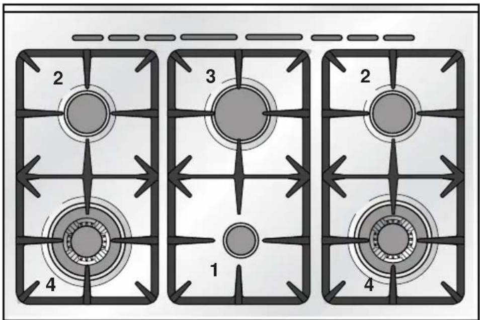
Fig. 1.1
TECHNICAL FEATURES - Cooking hob
- Auxiliary burner (A) 1,00 kW
- Semi-rapid burner (SR) 1,75 kW
- Rapid burner (R) 3,00 kW
- Triple-ring burner (TC) 3,50 kW
Important Note:
√ The electric ignition is incorporated in the knobs.
2 - CONTROL PANEL
Fig. 2.1

7
CONTROLS DESCRIPTION
- Gas oven/gas grill control knob
- 60' alarm control knob
- Front left burner control knob
- Rear left burner control knob
- Front central burner control knob
- Rear central burner control knob
- Rear right burner control knob
- Front right burner control knob
- Oven light switch
NB: Your appliance has been fitted with a cooling fan to achieve optimum efficiency of the controls and to ensure lower surface temperatures are maintained.
The cooling fan is thermostatically controlled and will operate when the oven is turned on and will continue to be heard running for a short period of time until the oven cavity has cooled down to a predetermined level.
3 - USE OF COOKING HOB
GAS BURNERS
Each burner is controlled by a gas tap assuring the opening and the closing of the gas supply.
Turning the knob so that the indicator line points to the symbols printed on the panel achieves the following functions:
- symbol ● : off

(nominal rate)
- symbol reduced rate
- To reduce the gas flow to minimum, rotate the knob anti-clockwise to point the indicator towards the small flame symbol.
- The maximum setting permits rapid boiling of liquids, whereas the minimum setting allows slower warming of food or maintaining simmering conditions of liquids.
- Other intermediate operating can be achieved by positioning the control knob indicator between the maximum and minimum setting, but not between the maximum and off positions.
N.B. When the cooker is not being used, set the gas knobs to their closed positions and also close the cock valve on the gas bottle or the main gas supply line.
To ignite the burner, the following instructions are to be followed:
1) Lightly press and turn the knob anticlockwise (fig. 3.2) and position the knob symbol printed on the control panel (fig. 3.1).
2) Press the knob to operate the electric ignition; or, in the case of a mains failure light the burner with a match or lighted taper.
3) Adjust the burner according to the setting required.

natural_image
Diagram of a circular device with internal components and droplet symbols, labeled Fig. 3.1 (no readable text or symbols)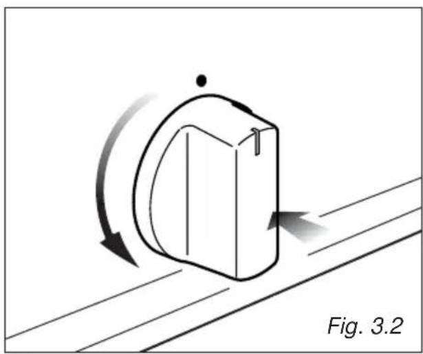
natural_image
Diagram of a mechanical component with curved arrows indicating motion, labeled Fig. 3.2 (no text or symbols on the diagram itself)CHOICE OF THE BURNER
On the control panel, near every knob, there is a diagram that indicates which burner is controlled by that knob.
The suitable burner must be chosen according to the diameter and the capacity used.
As an indication, the burners and the pots must be used in the following way:
It is important that the diameter of the pot be suitable to the potentiality of the burner so as not to compromise the high output of the burners and therefore energy waste.
A small pot on a large burner does not give you a boiling point in a shorter amount of time since the capacity of heat absorption of a liquid mass depends on the volume and the surface of the pot.
Caution! The cooking hob becomes very hot during operation. Keep children well out of reach.
BURNERS POT DIAMETER
| Auxiliary 12 - 14 cm |
| Semi-rapid 16 - 24 cm |
| Rapid 24 - 24 cm |
| Triple-ring 26 - 28 cm |
| Wok | max | 36 cm |
| do not use pans with concave or convex bases |

natural_image
Line drawing of a cooking pot on a stove (no text or symbols)
Fig. 3.3

natural_image
Illustration of a cooking pot on a stove with upward arrows indicating heating (no text or symbols)AIR FLOW (cooling fan)

natural_image
Illustration of a cooking pot with crossed X-shaped lines indicating resistance, placed on a stove (no text or symbols)AIR FLOW (cooling fan)

natural_image
Simple line drawing of a cooking pot with crossed X marks and a base, no text or symbols present.AIR FLOW (cooling fan)
CORRECT USE OF RAPID BURNER
Fig. 3.4
CORRECT USE OF TRIPLE-RING BURNER
The flat-bottomed pans are to be placed directly onto the pan-support.
To use the WOK you need to place the proper stand in order to avoid any faulty operation of the triple-ring burner (Fig. 3.5a - 3.5b).
IMPORTANT:
The special grille for wok pans (fig. 3.5b) MUST BE PLACED ONLY over the pan-rest for the triple-ring burner.


Attention: the oven door becomes very hot during operation. Keep children away.
GENERAL FEATURES
The oven is furnished completely clean; it is advisable, however, upon first use, to turn the oven on to the maximum temperature 205-eliminate possible traces of grease from the oven burner. The same operation should be followed for grill burner.
The gas oven is provided with:
- One gas burner (wattage: 6,20 kW), located at the bottom, providing safety device.
- One gas grill (wattage: 4,65 kW), located at the top of the oven, providing safety device.
OVEN BURNER
It carries out normal "oven cooking".
The gas flow to the burner is regulated by a thermostat which allows to maintain the oven temperature constant.
The control of the temperature is assured by a thermostatic probe positioned inside the oven.
The probe must be always kept in its housing, in a clean condition, as an incorrect position or encrustment may cause an alteration in the control of the temperature.
Moreover, the thermostat is fitted with a safety valve which automatically shuts off the gas supply when the flame goes out.
WARNING:
The door is hot, use the handle.
THERMOSTAT KNOB
The temperature knob is numbered from 150 to 285 (Fig. 4.1) indicating the increasing oven temperature value.
The thermostat which regulates the flow of gas to the oven burner has a safety valve which automatically shuts off the gas supply when the flame goes out.
The temperature is kept constant on the regulated value.

radar
| Angle (°) | Value | |-----------|-------| | 0 | 150 | | 30 | 165 | | 60 | 180 | | 90 | 195 | | 120 | 210 | | 150 | 225 | | 180 | 240 | | 210 | 255 | | 240 | 270 | | 270 | 285 |IGNITION OF THE OVEN BURNER
ATTENTION: Never turn the thermostat before opening the oven door.
To ignite the oven burner:
1 - Open the oven door to the full extent.
WARNING: Risk of explosion! The oven door must be open during this operation.
2 - Lightly press and turn the thermostat knob anti-clockwise (fig. 4.2) to max position "285 ★" (fig. 4.1), then press the knob firmly until the burner lights.
Never continue this operation for more than 15 seconds. If the burner has still not ignited, wait for about 1 minute prior to repeating the ignition.
To light the oven burner manually, approach a flame to the hole 'A' of the oven floor fig. 4.3.
3 – After lighting the burner, wait a few seconds before releasing the knob (until the safety valve stays open).
4 - Gently close the oven door and set the oven control knob to the required temperature.
If the flame extinguishes for any reason, the safety valve will automatically shut off the gas supply to the burner.
To re-light the burner, first turn the oven control knob to position ●, wait for at least 1 minute and then repeat the lighting procedure.

natural_image
Diagram of a mechanical component with directional arrows indicating motion, labeled Fig. 4.2 (no text or symbols on the diagram itself)For efficient oven preheating, we recommend that grill trays and racks are removed from the oven and replaced after about 15 minutes.

natural_image
Line drawing of a hand inserting a plug into an oven with a labeled component (A), no text or symbols present.IGNITION OF THE GRILL BURNER
Very important: the grill must always be used with the oven door ajar and with shield "A" mounted (Fig. 4.6).
Attention: the oven door becomes very hot during operation.
Keep children away.
The grill burner generates the infra-red rays for grilling.
To light the grill burner operate as follows:
ATTENTION: Never turn the thermostat before opening the oven door.
1 - Open the oven door to its full extent.
WARNING: Risk of explosion! The oven door must be open during this operation.
2 - Lightly press and turn the thermostat knob clockwise to the position (fig. 4.4).
3 – Press the knob right down to prime the electric ignition. Keep the knob pressed.
Never continue this operation for more than 15 seconds. If the burn-er has still not ignited, wait for about 1 minute prior to repeating the ignition.
In case of a power cut, press the knob and immediately put a lighted match to the right and left side of the burner (fig. 4.5).
4 – After lighting the burner, wait a few seconds before releasing the knob (until the safety valve stays open).
Do not close the oven door completely. The grill must always be used with the oven door slightly open and with shield "A" fitted (Fig. 4.6).
See specific instructions in 'USE OF THE GRILL'.
If the flame extinguishes for any reason, the safety valve will automatically shut off the gas supply to the burner.
To re-light the burner, first turn the oven control knob to position ●, wait for at least 1 minute and then repeat the lighting procedure.

natural_image
Diagram of a mechanical component on an inclined plane with motion arrows indicating rotation (no text or symbols)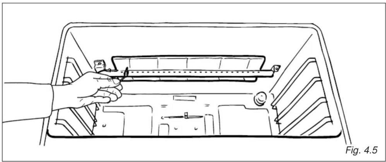
natural_image
Line drawing of a hand holding a tool inside a vehicle intake frame (no text or symbols)USE OF THE GRILL
IMPORTANT: the grill must always be used with the oven door slightly open and with the shield "A" fitted (Fig. 4.6).
Fit shield "A" (fig. 4.6) to protect the control panel from the heat.
Turn on the grill, as explained in the preceding paragraphs and let the oven preheat for about 5 minutes with the door ajar.
Introduce the food to be cooked, positioning the rack as close to the grill as possible.
The drip tray pan should be placed under the rack to catch the cooking juices and fats.
Note: It is recommended that you do not grill for longer than 30 minutes at any one time.
Attention: the oven door becomes very hot during operation.
Keep children away.
OVEN LIGHT
The cooker is equipped with a light that illuminates the oven to enable visually controlling the food that is cooking.
This light is controlled by a push button on the control panel (fig. 4.7).
natural_image
Simple icon showing a monitor and a sun symbol (no text or labels)Fig. 4.7

OVEN COOKING
Before introducing the food, preheat the oven to the desired temperature.
For a correct preheating operation, it is advisable to remove the tray from the oven and introduce it together with the food, when the oven has reached the desired temperature.
Check the cooking time and turn off the oven 5 minutes before the theoretical time to recuperate the stored heat.
For efficient oven preheating, we recommend that grill trays and racks are removed from the oven and replaced after about 15 minutes.
COOKING EXAMPLES
Temperatures and times are approximate as they vary depending on the quality and amount of food.
Remember to use ovenproof dishes and to adjust the oven temperature during cooking if necessary.
| DISHES | TEMPERATURE |
| Lasagne 190° | |
| Baked pasta | 190° |
| Pizza | 220° |
| Creole rice | 190° |
| Baked onions | 190° |
| Spinach crêpes | 185° |
| Potatoes baked in milk | 185° |
| Stuffed tomatoes | 180° |
| Cheese soufflé | 170° |
| Roast veal | 180° |
| Grilled veal chops | 210° |
| Chicken breasts with tomato | 180° |
| Grilled chicken - roast chicken | 190° |
| Veal loaf | 175° |
| Roast beef | 170° |
| Fillet of sole | 175° |
| Aromatic hake | 170° |
| Beignets | 160° |
| Ring cake | 150° |
| Plum tart | 170° |
| Jam tartlets | 160° |
| Sponge cake | 170° |
| Sweet dough | 160° |
| Sweet puffs | 170° |
| Plain sponge cake | 170° |
5 - MINUTE COUNTER
ALARM 60'
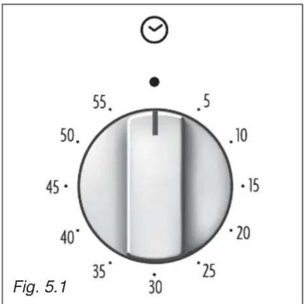
The minute counter is a timed acoustic warning device which can be set for a maximum of 60 minutes.
The knob (fig. 5.1) must be rotated clockwise as far as the 60 minute position and then set to the required time by rotating it anticlockwise.
GENERAL ADVICE
- When the appliance is not being used, it is advisable to keep the gas tap closed.
- Every now and then check to make sure that the flexible tube that connects the gas line or the gas cylinder to the appliance is in perfect condition and eventually substitute it if it shows signs of wearing or damage.
- The periodical lubrication of the gas taps must be done only by specialized personnel.
- If a tap becomes stiff, do not force; contact your local Service Centre.
- Important:
Before any operation of cleaning and maintenance disconnect the appliance from the electrical network.
ENAMELLED PARTS
All the enamelled parts must be cleaned with a sponge and soapy water or other non-abrasive products.
Dry preferably with a soft cloth.
Acidic substances like lemon juice, tomato sauce, vinegar etc. can damage the enamel if left too long.
Attention
The appliance gets very hot, mainly around the cooking areas. It is very important that children are not left alone in the kitchen when you are cooking.
Do not use a steam cleaner because the moisture can get into the appliance thus make it unsafe.
STAINLESS STEEL SURFACES (Stainless steel models)
The stainless steel front panels on this cooker (facia, oven door, bottom panel) are protected by a finger-print proof lacquer.
To avoid damaging this lacquer, do not clean the stainless steel with abrasive cleaners or abrasive cloths or scouring pads.
ONLY SOAP/WARM WATER MUST BE USED TO CLEAN THE STAINLESS STEEL SURFACES.
ALUMINIUM PARTS AND SILK-SCREEN PRINTED SURFACES
Clean using an appropriate product. Always dry thoroughly.
IMPORTANT: these parts must be cleaned very carefully to avoid scratching and abrasion. You are advised to use a soft cloth and neutral soap.
CAUTION: Do not use abrasive substances or non-neutral detergents as these will irreparably damage the surface.
Do not use harsh abrasive cleaners or sharp metal scrapers to clean the oven door glass since they can scratch the surface, which may result in shattering of the glass.
GAS TAPS
In the event of operating faults in the gas taps, call the Service Department.
BURNERS
They can be removed and washed with soapy water only.
They will remain always perfect if cleaned with products used for silverware.
After cleaning or wash, check that burner-caps and burner-heads are dry before placing them in the respective housings.
CORRECT REPLACEMENT OF THE BURNERS
It is very important to check that the burner flame distributor F and the cap C has been correctly positioned (see fig. 6.1 - 6.2) - failure to do so can cause serious problems.
Check that the electrode "S" (fig. 6.1) is always clean to ensure trouble-free sparking.
Note: To avoid damage to the electric ignition do not use it when the burners are not in place.

Fig. 6.1

Fig. 6.2
TRIPLE RING BURNER
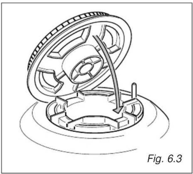
The triple ring burner must be correctly positioned (see fig. 6.3); the burner rib must be enter in their logement as shown by the arrow.
The burner correctly positioned must not rotate (fig. 6.4).
Then position the cap A and the ring B (fig. 6.4 - 6.5).
natural_image
Mechanical assembly diagram showing a rotating component with a curved arrow indicating motion, labeled 'Fig. 6.3' (no text or symbols on the diagram itself)

natural_image
Three-step diagram showing a mechanical component being cut with X marks, labeled Fig. 6.5 (no text or symbols on the diagrams themselves)INSIDE OF OVEN
The oven should always be cleaned after use when it has cooled down.
The cavity should be cleaned using a mild detergent solution and warm water. Suitable proprietary chemical cleaners may be used after first consulting with the manufacturers recommendations and testing a small sample of the oven cavity. Abrasive cleaning agents or scouring pads/cloths should not be used on the cavity surface.
NOTE: The manufacturers of this appliance will accept no responsibility for damage caused by chemical or abrasive cleaning.
Let the oven cool down and pay special attention no to touch the hot heating elements inside the oven cavity.
ASSEMBLY AND DISMANTLING OF THE SIDE RUNNER FRAMES
- Fit the side runner frames into the holes on the side walls inside the oven (Fig. 6.6)
- Slide the tray and rack into the runners fig. 6.7.
The rack must be fitted so that the safety catch, which stops it sliding out, faces the inside of the oven. - To dismantle, operate in reverse order.
OVEN FLOOR
The oven floor "F" (fig. 6.8) can be easily removed to facilitate cleaning.
Remember to replace the floor correctly afterwards.
Be careful not to confuse the tray "L" with the oven floor "F" (fig. 6.8).

natural_image
Technical line drawing of a mechanical component with spring-loaded housing and mounting bracket (no text or symbols)
natural_image
Technical diagram showing two views of a mechanical or structural component with internal channels and fasteners, labeled Fig. 6.7 (no text or symbols on the diagrams themselves)
natural_image
Technical line drawing of a kitchen appliance with a tray and door, labeled Fig. 6.9 (no text or symbols on the diagram itself)
natural_image
Technical line drawing of a mechanical assembly with mounting feet and a bracket (no text or symbols)OVEN DOOR
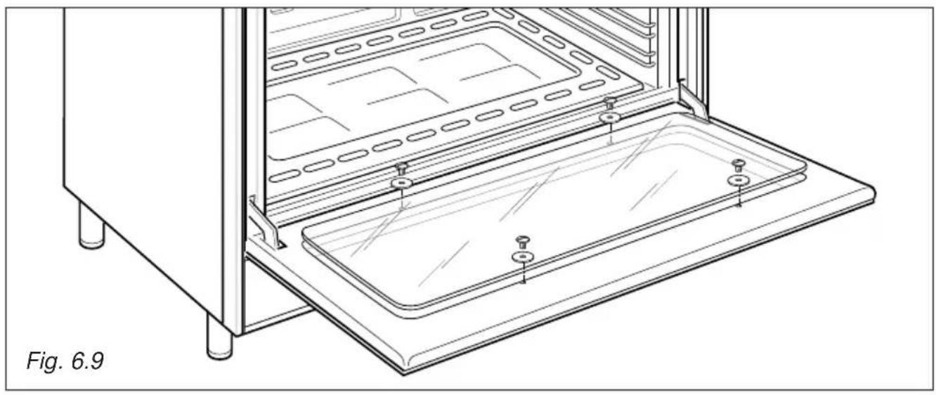
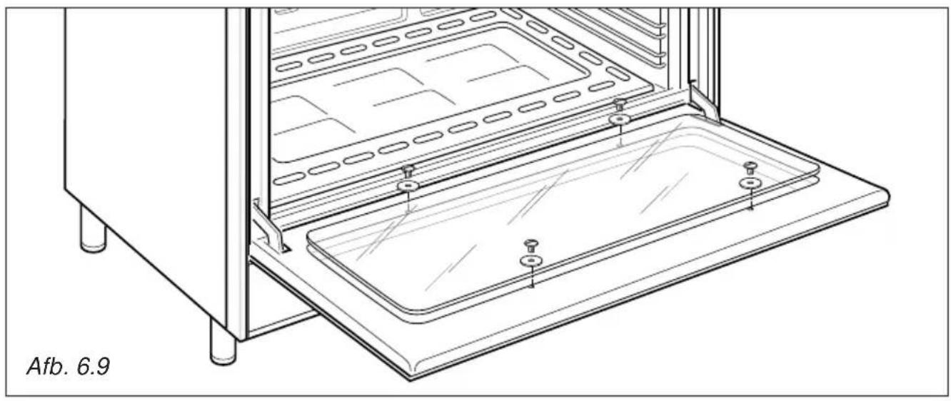
The internal glass panel can be easily removed for cleaning by unscrewing the 4 retaining screws (Fig. 6.9)
REPLACING THE OVEN LIGHT BULB
Switch the cooker off at the mains.
When the oven is cool unscrew and replace the bulb with another one resistant to high temperatures (300°C), voltage 230 V (50 Hz), 15 W, E14.
Note: Oven bulb replacement is not covered by your guarantee.
STORAGE COMPARTMENT
The storage compartment is accessible through the pivoting panel (fig. 6.10).
Do not store flammable material in the oven or in the storage compartment.
REMOVING THE OVEN DOOR
The oven door can easily be removed as follows:
- Open the door to the full extent (fig. 6.11A).
- Attach the retaining rings to the hooks on the left and right hinges (fig. 6.11B).
- Hold the door as shown in fig. 6.11.
- Gently close the door and withdraw the lower hinge pins from their location (fig. 6.11C).
- Withdraw the upper hinge pins from their location (fig. 6.11D).
- Rest the door on a soft surface.
- To replace the door, repeat the above steps in reverse order.

natural_image
Technical line drawing of a mechanical bracket assembly (no text or symbols)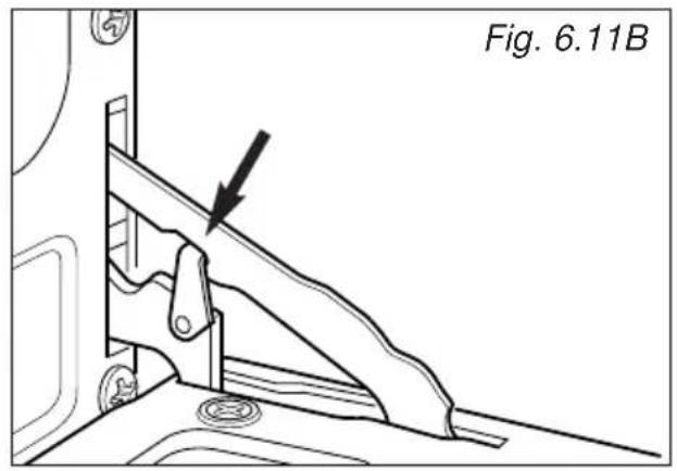

natural_image
Line drawing of hands installing or adjusting a rectangular panel on a wall, labeled Fig. 6.11 (no text or symbols on the diagram itself)
natural_image
Technical line drawing of a mechanical assembly with no visible text or symbols
natural_image
Technical line drawing of a mechanical bracket assembly (no text or symbols)Advice for the Installer
IMPORTANT
- Cooker installation and regulation must only be carried out by QUALIFIED TECHNICIANS and in compliance with the local safety standards. Failure to observe this rule will invalidate the warranty.
- The electrical mains outlet, if located behind the cooker, must not be higher than 18 cm above the floor level.
- Some appliances are supplied with a protective film on steel and aluminium parts. This film must be removed before using the cooker.
INSTALLATION
This cookers has class "2/1" overheating protection so that it can be installed in a cabinet.
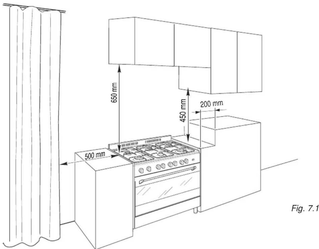
The appliance must be kept no less than 200 mm away from any side wall which exceed the height of the hob surface (fig. 7.1).
The furniture walls adjacent to the cooker must be made of material resistant to heat.
The veneered syntetical material and the glue used must be resistant to a temperature of 90^ C in order to avoid ungluing or deformations.
The cooker may be located in a kitchen, a kitchen/diner or bed-sitting room but not in a room containing a bath or shower.
Curtains must not be fitted immediately behind appliance or within 500 mm of the sides.
It is essential that the cooker is positioned as stated below.
The cooker must be installed by a qualified technician and in compliance with a local safety standards.
If the cooker is located on a pedestal it is necessary to provide safety measures to prevent falling out.
BACKGUARD
Before installing the cooker, assemble the backguard "C" (fig. 7.2).
- The backguard "C" can be found packed at the rear of the cooker.
- Before assembling remove any protective film/adhesive tape.
- Remove the two spacers "A" and the screw "B" from the rear of the cooktop.
- Assemble the backguard as shown in figure 7.2 and fix it by screwing the central screw "B" and the spacers "A".

FITTING THE ADJUSTABLE FEET
The adjustable feet must be fitted to the base of the cooker before use (fig. 7.3).

natural_image
Technical line drawing of a structural support frame with mounting holes and mounting feet (no text or symbols)The cooker may be levelled by screwing the lower ends of the feet IN or OUT (fig. 7.4)

natural_image
Diagram of a mechanical assembly with directional arrows indicating motion, labeled Fig. 7.4 (no text or symbols on the diagram itself)
natural_image
Line drawing of two people assembling a large oven on a tiled floor (no text or symbols)
natural_image
Line drawing of a person operating a cart with a diagonal line crossing, labeled 'Fig. 7.6' (no text or symbols on the diagram itself)
natural_image
Line drawing of a person using a portable stove with a diagonal line crossing the floor, labeled 'Fig. 7.7' (no text on diagram)WARNING
When raising cooker to upright position always ensure two people carry out this manoeuvre to prevent damage to the adjustable feet (fig. 7.5).
WARNING
Be careful: DO NOT LIFT the cooker by the door handle when raising to the upright position (fig. 7.6).
WARNING
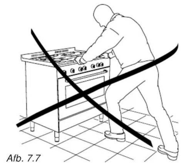
When moving cooker to its final position DO NOT DRAG (fig. 7.7). Lift feet clear of floor (fig. 7.5).
In the room chosen to accommodate the gas appliance, there must be an adequate natural draft to allow combustion of the gas.
The flow of air must come directly from one or more openings made in the outside walls with a free area of at least 100 cm ^2 .
If the appliance does not have a no-flame safety device this opening must have an area of at least 200 cm ^4 .
The vents must be positioned close to the floor, preferably on the opposite side to the combustion discharge outlet and must be designed in such a way that they cannot be obstructed either from the inside or the outside.
When it is not possible to provide the necessary vents, the draft may be supplied from an adjacent room, ventilated in the required manner, provided it is not a bedroom or an area at risk.
In this event, the door of the kitchen must be opened to allow the draft to enter the room.
There must be a distance of at least 650 mm between the hob of the cooker and any wall cupboard or extractor hood positioned immediately above (see fig. 7.8).

This appliance is not connected to a device to evacuate the combustion products. This must be installed and connected in conformity with the installation rules in force. Pay special care to room ventilation as well.
DISCHARGING PRODUCTS OF COMBUSTION
Extractor hoods connected directly to the outside must be provided, to allow the products of combustion of the gas appliance to be discharged (fig. 7.8).
If this is not possible, an electric fan may be used, attached to the external wall or the window; the fan should have a capacity to circulate air at an hourly rate of 3-5 times the total volume of the kitchen (fig. 7.9).
The fan can only be installed if the room has suitable vents to allow air to enter, as described under the heading "Choosing suitable surroundings".

The walls adjacent to the cooker must be of material resistant to heat.

Cat: II 2L 3B/P
GAS CONNECTION
The connection must be executed by a qualified technician according to the relevant standards.
The appliance is predisposed and calibrated to operate with the gas indicated on the specifications plate.
Ensure that the room in which the cooker is to be installed is adequately ventilated, in compliance with applicable regulations.
Connection to the gas supply pipe or gas cylinder must be made in accordance with the requirements of the applicable regulations.
The gas supply is connected at the rear of the cooker (fig. 8.1) to the R or L terminal of the gas inlet pipe; the connection pipe must not cross the rear of the appliance.
The terminal not used must be closed off with the plug T and gasket.
Before installation, make sure that the local distribution conditions (type of gas and its pressure) and the adjustment of this appliance are compatible. The appliance adjustment conditions are given on the plate or the label.

Fig. 8.1
Use rigid or flexible connection pipes which comply with applicable regulations.
If compression fittings are used, tighten firmly using two spanners (fig. 8.3).
In particular, make sure that:
- the flexible hose does not come into contact with any parts of the cooker with surface temperatures in excess of 70^ ;
- the flexible hose does not exceed 75 cm in length and does not come into contact with sharp edges or corners;
- the hose is not under tension or twisted and is not kinked or too tightly bent;
- the connection with rigid metal pipes should not cause stresses to the gas ramp.
- we advise replacing the gasket on the slightest sign of deformation or imperfection.
- the hose can easily be inspected along its entire length to check its condition; hoses should replaced after a maximum of three years.
- the cylinder cock or the supply cock immediately ahead of the appliance is closed whenever the cooker is not in use.
The fitting (fig. 8.2) is made up of:
A - Gas train terminal fitting (rh or lh)
B - Gasket
C - Conical connector
IMPORTANT:
The gasket "B" (fig. 8.2) is the element that guarantees the seal in the gas connection. It is recommended that it be replaced whenever it shows even the slightest deformation or imperfection.
To replace the conical connector "C" or to screw the connecting tube it is necessary to operate with 2 spanners (fig. 8.3).
After connecting to the mains, check that the couplings are correctly sealed, using soapy solution, but never a naked flame.

Fig. 8.2

natural_image
Illustration of hands using a wrench to tie a rope or cable (no text or symbols present)Gas maintenance
REPLACEMENT OF THE COOKTOP BURNER INJECTORS
Select the injectors to be replaced according to the "Table for the choice of the injectors".
To replace the injectors proceed as follows:
- Remove pan supports and burners from the cooktop.
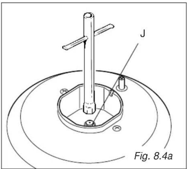
- Using a wrench, substitute the nozzle injectors "J" (fig. 8.4a, 8.4b) with those most suitable for the kind of gas for which it is to be used.
ADJUSTING OF THE MINIMUM OF THE TOP BURNERS
In the minimum position the flame must have a length of about 4 mm and must remain lit even with a quick turn from the maximum position to that of minimum.
The flame adjustment is done in the following way:
- Turn on the burner
- Turn the tap to the MINIMUM position
- Take off the knob
- With a small flat screwdriver turn the screw inside the tap rod to the correct regulation (fig. 8.5).
Normally for G30/G31, tighten up the regulation screw.
The burners are conceived in such a way so as not to require the regulation of the primary air.


natural_image
Line drawing of a tool with a circular head and handle, labeled Fig. 8.5 (no text or symbols on the diagram itself)NL
TABLE FOR THE CHOICE OF THE INJECTORS - Cat: II 2L 3B/P
| BURNERS 28-30/30 | Nam25ambar Power [kW] | Reduced Power [kW] | G30/G31 G 25 | |||
| ∅ injector [1/100 mm] | Ring opening [mm] | ∅ injector [1/100 mm] | Ring opening [mm] | |||
| Auxiliary (A) 1,00 0,30 | 50 - 72 (F1) | - | ||||
| Semi-rapid (SR) 1,75 0,45 65 - 94 (Y) | - | |||||
| Rapid (R) 3,00 0,75 85 | - 121 (F2) | - | ||||
| Triple-ring (TC) 3,50 1 | 50 95 - 138 (F3) | - | ||||
| Oven | 6,20 | 1,30 | 120 | 8 * | 190 | 1,5 * |
| Grill | 4,65 | - 107 | fully open * | 170 | 1,5 * | |
* = Reference value
| AIR VENT NECESSARY FOR GAS COMBUSTION = (2 m3/h x kW) | |
| BURNERS | Air vent necessary [m3/h] |
| Auxiliary (A) | 2,00 |
| Semirapid (SR) | 3,50 |
| Rapid (R) | 6,00 |
| Triple-ring (TC) | 7,00 |
| Oven | 12,40 |
| Grill | 9,30 |
REPLACEMENT OF THE OVEN BURNER INJECTOR
- Lift and remove the lower panel inside the oven.
- Unscrew and remove the burner securing screw A (fig. 8.6).
- Slacken screw B (fig. 8.6).
- Withdraw the burner in the manner shown in figure 8.7, and rest it inside the oven. Take care not to damage the wire to the ignition electrode and the safety valve probe.
- Using a 10 mm box spanner, unscrew the injector (indicated by the arrow in fig. 8.7) and replace with a new injector selected in accordance with the "TABLE FOR THE CHOICE OF THE INJECTORS"; then replace the burner repeating the above steps in reverse order.


REPLACEMENT OF THE GRILL BURNER INJECTOR
- Unscrew and remove the burner securing screw 'C' (fig. 8.8).
- Slacken screw 'D' (fig. 8.8).
- Move the burner in the manner shown in figure 8.9.
Take care not to damage the wire to the ignition electrode and the safety valve probe.
- Using a 10 mm box spanner, unscrew the injector 'V' (indicated by the arrow in fig. 8.9) and replace with a new injector selected in accordance with the "TABLE FOR THE CHOICE OF THE INJECTORS"; then replace the burner repeating the above steps in reverse order.


Fig. 8.8

ADJUSTMENT OF THE OVEN BURNER MINIMUM
This needs to be done only for the oven burner (the grill is a fixed capacity) by acting on the thermostat.
Considering that in the minimum position the flame must have a length of about 4 mm and must remain lit even with a brusque passage from the maximum position to that of minimum.
The flame adjustment is done in the following way:
- turn on the burner by setting the thermostat knob on position 285
- remove the knob and unscrew the bypass screw (fig. 8.12) about three times by passing a small flat screw-driver (∅ 3 mm blade, 100 mm length) through the panel opening
- re-mount the knob and let the oven heat up for about 10 minutes, then bring the knob to position 150 minimum) to operate the thermostat bypass
- after having removed the knob again and being very careful not to turn the tap rod, slowly screw the by-pass screws "G" (fig. 8.12) until you obtain a flame of 3-4 mm in height.
N.B. For G30/G31 the by-pass screw must be fixed thoroughly.

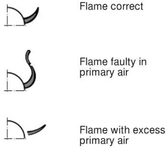
| Flame faulty in correct with excess primary air primary air | ||
| long, yellow clear short and sharpand interior blue too blue interiortrembling cone cone tending todetach | ||
| CAUSE | ||
| air regulating correct air regulatingtube, too distance of tube, tooclosed the tube open |
IMPORTANT
All intervention regarding installation maintenance of the appliance must be fulfilled with original factory parts.
The manufacturer declines any liability resulting from the non-compliance of this obligation.
LUBRICATION OF THE GAS TAPS
- In case of difficulty in the gas taps operation, call Service.
9 - ELECTRICAL SECTION
IMPORTANT: The cooker must be installed in accordance with the manufacturer's instructions. Incorrect installation, for which the manufacturer accepts no responsibility, may cause injury to persons or animals etc.
GENERAL
- Connection to the mains must be carried out by qualified personnel in accordance with current regulations.
- The appliance must be connected to the mains checking that the voltage corresponds to the value given in the rating plate and that the electrical cable sections can withstand the load specified on the plate.
- The plug must be connected to an earthed socket in compliance with safety standards.
- The appliance can be connected directly to the mains placing an omnipolar switch with minimum opening between the contacts of 3 mm between the appliance and the mains.
- The power supply cable must not touch the hot parts and must be positioned so that it does not exceed 75^ at any point.
- Once the appliance has been installed, the switch or socket must always be accessible.
N.B. For connection to the mains, do not use adapters, reducers or branching devices as they can cause overheating and burning.
If the installation requires alterations to the domestic electrical system or if the socket and appliance plug are incompatible, call an expert.
He should also check that the socket cable section is suitable for the power absorbed by the appliance.
Before effecting any intervention on the electrical parts of the appliance, the connection to the network must be interrupted.
The connection of the appliance to earth is mandatory.
The manufacturer declines all responsibility for any inconvenience resulting from the inobservance of this condition.
ELECTRICAL FEEDER CABLE CONNECTION
To connect the supply cable:
- Remove the screws securing the cover "A" on the rear of the cooker (fig. 9.1).
- Feed the supply cable through the cable clamp "D". The supply cable must be of a suitable size for the current requirements of the appliance; see the section "Feeder cable section".
- Connect the wires to the terminal block "B" as shown in the diagram in figure 9.2; or connect the phase wires to the terminal block "B" and the earth wire to the terminal PE as shown in figure 9.1.
- Take up any slack in the cable and secure with the cable clamp "D".
- Replace the cover "A".
FEEDER CABLE SECTION Type "HO5RR-F"
230 V 8×0.75 mm
2 (*)
(*) - Connection possible with plug and outlet


natural_image
Diagram of a mechanical component with curved arrows indicating motion, labeled 'Afb. 3.2' (no text or symbols on the diagram itself)KEUZE VAN BRANDERS
natural_image
Line drawing of a cooking pot on a stove (no text or symbols)
Afb. 3.3

natural_image
Illustration of a cooking pot with upward arrows indicating heating or cooking process (no text or symbols)LUCHTSTRAAL (koelventilator)

natural_image
Simple line drawing of a cooking pot with crossed x marks and an upward arrow, no text or symbols present.LUCHSTRAAL (koelventilator)

natural_image
Illustration of a cooking pot with crossed X marks and a side-mounted base (no text or symbols)LUCHTSTRAAL (koelventilator)
natural_image
Diagram of a mechanical component with directional arrows indicating motion, labeled 'Afb. 4.2' (no text or symbols on the diagram itself)
ONTSTEKING VAN DE BRANDER VAN DE GRILL
natural_image
Diagram of a mechanical component on an inclined plane with motion arrows indicating direction (no text or symbols)
natural_image
Line drawing of a hand holding a tool inside a vehicle intake frame (no text or symbols)GEBRUIK VAN DE ROOSTOVEN
natural_image
Simple icon showing a monitor and a sun symbol (no text or labels)Afb. 4.7

KOKEN MET DE OVEN
natural_image
Mechanical assembly diagram showing a rotating component with a curved arrow indicating motion (no text or symbols)

OVENRUIMTE
Maak de ovenruimte na iedere kook- beurt schoon.
natural_image
Technical line drawing of a mechanical component with spring-loaded housing and mounting bracket (no text or symbols)
natural_image
Technical diagram showing two views of a mechanical or structural assembly with internal components and fasteners (no text or symbols)
natural_image
Technical line drawing of a kitchen appliance with a tray and door, labeled 'Afb. 6.9' (no other text or symbols)
natural_image
Technical line drawing of a mechanical assembly with mounting feet and a bracket (no text or symbols)OVENDEUR
natural_image
Line drawing of hands installing or adjusting a rectangular panel on a door frame (no text or symbols)
natural_image
Technical line drawing of a structural support frame with mounting holes and mounting feet (no text or symbols)HET FORNUIS WATERPAS ZETTEN
natural_image
Diagram of a mechanical assembly with rotating components and directional arrows, labeled 'Afb. 7.4' (no text or symbols on diagram itself)
natural_image
Line drawing of two people assembling a large stove on a tiled floor (no text or symbols)
natural_image
Line drawing of a person using a portable stove with crossed lines indicating resistance or crossed-out (no text or symbols)WAARSCHUWING
natural_image
Illustration of hands using a wrench to tie a rope or cable (no text or symbols present)natural_image
Line drawing of a tool with a circular head and handle, labeled 'Afb. 8.5' (no text or symbols on the diagram itself)
TABEL VAN DE INSPUITERS - Cat: II 2L 3B/P
| BRANDERS | NOMINAAL DEBIET [kW] | VERMINDER DEBIET [kW] | G30/G31 G 25 28-30/30 mbar 25 mbar | |||
| ∅ spuitstuk [1/100 mm] | Open Leistung [mm] | ∅ spuitstuk [1/100 mm] | Open Leistung [mm] | |||
| Hulpbrander (A) 1,00 0, | 30 50 - 72 | (F1) - | ||||
| Halfsnelle (SR) 1,75 0,4 | 5 65 - 94 | (Y) - | ||||
| Snelle brander (R) 3,00 | 0,75 85 - 1 | 21 (F2) - | ||||
| Driedubbele kroon (TC) | 3,50 1,50 | 95 - 138 (F3) - | ||||
| Oven | 6,20 | 1,30 | 120 | 8* | 190 | 1,5* |
| Grill | 4,65 | - 107 | max * 170 | 1,5 | * | |
Descriptions and illustrations in this booklet are given as simply indicative.
The manufacturer reserves the right, considering the characteristics of the models described here, at any time and without notice, to make eventual necessary modifications for their construction or for commercial needs.
- Nederlands
- DECLARATION OF CE CONFORMITY
- IMPORTANT INSTRUCTIONS AND ADVICE FOR THE USE OF ELECTRICAL APPLIANCES
- FIRST USE THE OVEN
- Important:
- IMPORTANT SAFEGUARDS AND RECOMMENDATIONS
- ● WARNING
- TECHNICAL FEATURES - Cooking hob
- Important Note:
- - CONTROL PANEL
- CONTROLS DESCRIPTION
- - USE OF COOKING HOB
- GAS BURNERS
- CHOICE OF THE BURNER
- CORRECT USE OF TRIPLE-RING BURNER
- GENERAL FEATURES
- OVEN BURNER
- THERMOSTAT KNOB
- IGNITION OF THE OVEN BURNER
- IGNITION OF THE GRILL BURNER
- ATTENTION: Never turn the thermostat before opening the oven door.
- USE OF THE GRILL
- OVEN LIGHT
- OVEN COOKING
- COOKING EXAMPLES
- - MINUTE COUNTER
- ALARM 60'
- GENERAL ADVICE
- ENAMELLED PARTS
- Attention
- STAINLESS STEEL SURFACES (Stainless steel models)
- ALUMINIUM PARTS AND SILK-SCREEN PRINTED SURFACES
- GAS TAPS
- BURNERS
- CORRECT REPLACEMENT OF THE BURNERS
- TRIPLE RING BURNER
- INSIDE OF OVEN
- ASSEMBLY AND DISMANTLING OF THE SIDE RUNNER FRAMES
- OVEN FLOOR
- OVEN DOOR
- REPLACING THE OVEN LIGHT BULB
- STORAGE COMPARTMENT
- REMOVING THE OVEN DOOR
- Advice for the Installer
- IMPORTANT
- INSTALLATION
- BACKGUARD
- FITTING THE ADJUSTABLE FEET
- WARNING
- DISCHARGING PRODUCTS OF COMBUSTION
- GAS CONNECTION
- The fitting (fig. 8.2) is made up of:
- Gas maintenance
- REPLACEMENT OF THE COOKTOP BURNER INJECTORS
- ADJUSTING OF THE MINIMUM OF THE TOP BURNERS
- NL
- TABLE FOR THE CHOICE OF THE INJECTORS - Cat: II 2L 3B/P
- REPLACEMENT OF THE OVEN BURNER INJECTOR
- REPLACEMENT OF THE GRILL BURNER INJECTOR
- ADJUSTMENT OF THE OVEN BURNER MINIMUM
- LUBRICATION OF THE GAS TAPS
- - ELECTRICAL SECTION
- GENERAL
- ELECTRICAL FEEDER CABLE CONNECTION
- FEEDER CABLE SECTION Type "HO5RR-F"
- KEUZE VAN BRANDERS
- ONTSTEKING VAN DE BRANDER VAN DE GRILL
- GEBRUIK VAN DE ROOSTOVEN
- KOKEN MET DE OVEN
- OVENRUIMTE
- OVENDEUR
- HET FORNUIS WATERPAS ZETTEN
- WAARSCHUWING
- TABEL VAN DE INSPUITERS - Cat: II 2L 3B/P
Brand : M-SYSTEM
Model : DOK-96G
Category : Cooker