
FK-95 - Cooker M-SYSTEM - Free user manual and instructions
Find the device manual for free FK-95 M-SYSTEM in PDF.


| Product Type | Free-standing electric cooker |
| Brand | M-System |
| Model | FK-95 |
| Energy Source | Electric |
| Hob Type | Vitroceramic glass ceramic |
| Number of Cooking Zones | 5 |
| Special Zones | Double cooking zone (Ø210/120 mm, 2100/700 W), Oval zone (140x250 mm, 1800/1000 W), 3-circuit radiant zones (Ø180 1700 W, Ø145 1200 W) – 3 of them |
| Oven Type | Multi-function electric oven |
| Oven Functions | 7 functions: convection, grilling, fan-assisted, defrost, ventilated grill, etc. |
| Oven Heating Elements | Top, bottom, grill, circular fan element – total oven power approx. 8.6 kW |
| Oven Capacity | Approximately 60–70 litres |
| Temperature Range | 50°C to 250°C (thermostat knob up to 250) |
| Controls | Rotary knobs for hob zones, thermostat and function selector, electronic clock/programmer with timer and automatic cooking |
| Installation Type | Freestanding, requires minimum 50 mm side clearance, adjustable feet |
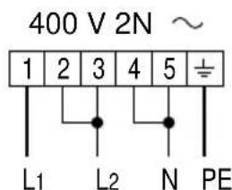
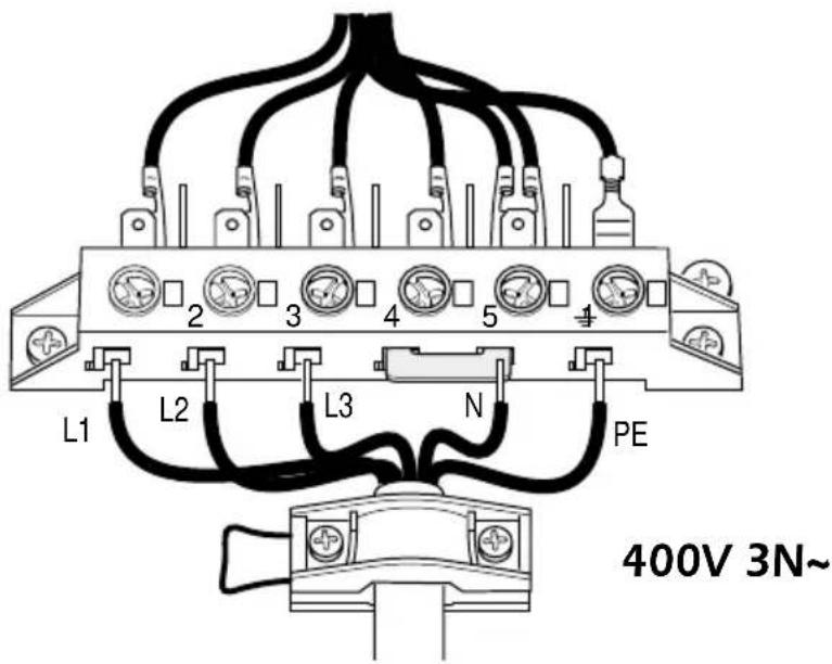
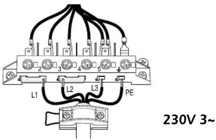
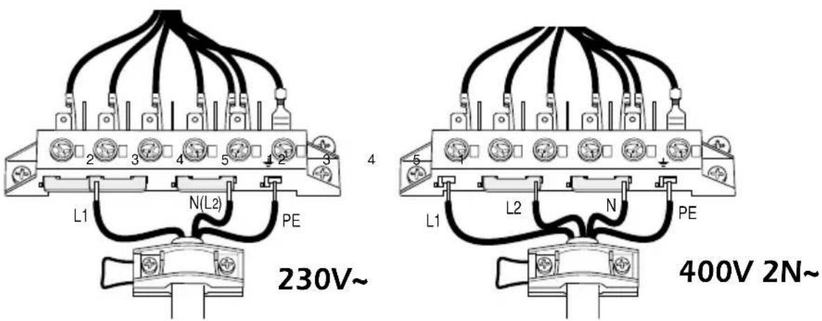
| Electrical Connection | Multiple options: 230V~, 230V 3~, 400V 3N~, 400V 2N~; cable section according to connection type |
| Dimensions (W x D) | 750 mm x 500 mm (approx) |
| Oven Door | Removable, with internal glass panel for cleaning |
| Cleaning | Enamel oven interior, stainless steel front (soap water only), vitroceramic hob with scraper |
| Safety Features | Residual heat indicators per zone, thermolimiter on hob, safety cooling fan |
| Accessories Included | Wire shelf, oven tray, grids, adjustable feet, backguard |
| Spare Parts | Oven bulb (15W, 300°C, E14), adjustable feet |
Frequently Asked Questions - FK-95 M-SYSTEM
User questions about FK-95 M-SYSTEM
0 question about this device. Answer the ones you know or ask your own.
Ask a new question about this device
Download the instructions for your Cooker in PDF format for free! Find your manual FK-95 - M-SYSTEM and take your electronic device back in hand. On this page are published all the documents necessary for the use of your device. FK-95 by M-SYSTEM.
USER MANUAL FK-95 M-SYSTEM
Instruction for the use
Installation advice
CE
English Page Instruction for the use - Installation advice
natural_image
Symbol of a trash bin crossed with a diagonal line, no text or numbers presentBELANGRIJKE RAADGEVINGEN
natural_image
Circular maze pattern with concentric rings and a central oval, labeled 'Afb. 3.2' at bottom (no other text or symbols)DOPPELE KOOKZONES
CONTROLELAMPJE "PLAAT WARMI"
natural_image
Line drawing of a hand using a tool to brush or mark on a circular surface with scattered debris (no text or symbols)Afb. 3.8
4 - ELEKTRISCHE MULTIFUNKTIE OVEN
Opgelet :
Uurregeling/Annulering programma's

(1 segment = 12 minutes)
Verlichte externe segmenten
(1 segment = 1 minuut)
TIMER
Verlichte externe segmenten (1 segment = 1 minuut)


Afb. 5.1
KLOK (Afb. 5.2)
natural_image
Line drawing of an oven interior showing the exterior and floor panels with mounting points (no text or symbols)Afb. 6.1
OVENDEUR
natural_image
Technical line drawing of a mechanical assembly with mounting feet and a vertical component (no text or symbols)Afb. 6.2
OVEN
natural_image
Technical diagram of a mechanical assembly with spring-loaded components and directional arrows (no text or symbols)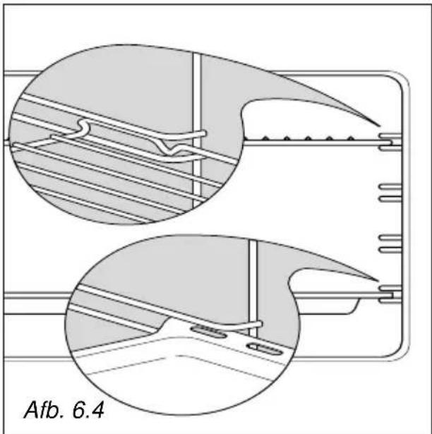
natural_image
Technical diagram showing two views of a mechanical component with internal channels and mounting holes (no text or symbols)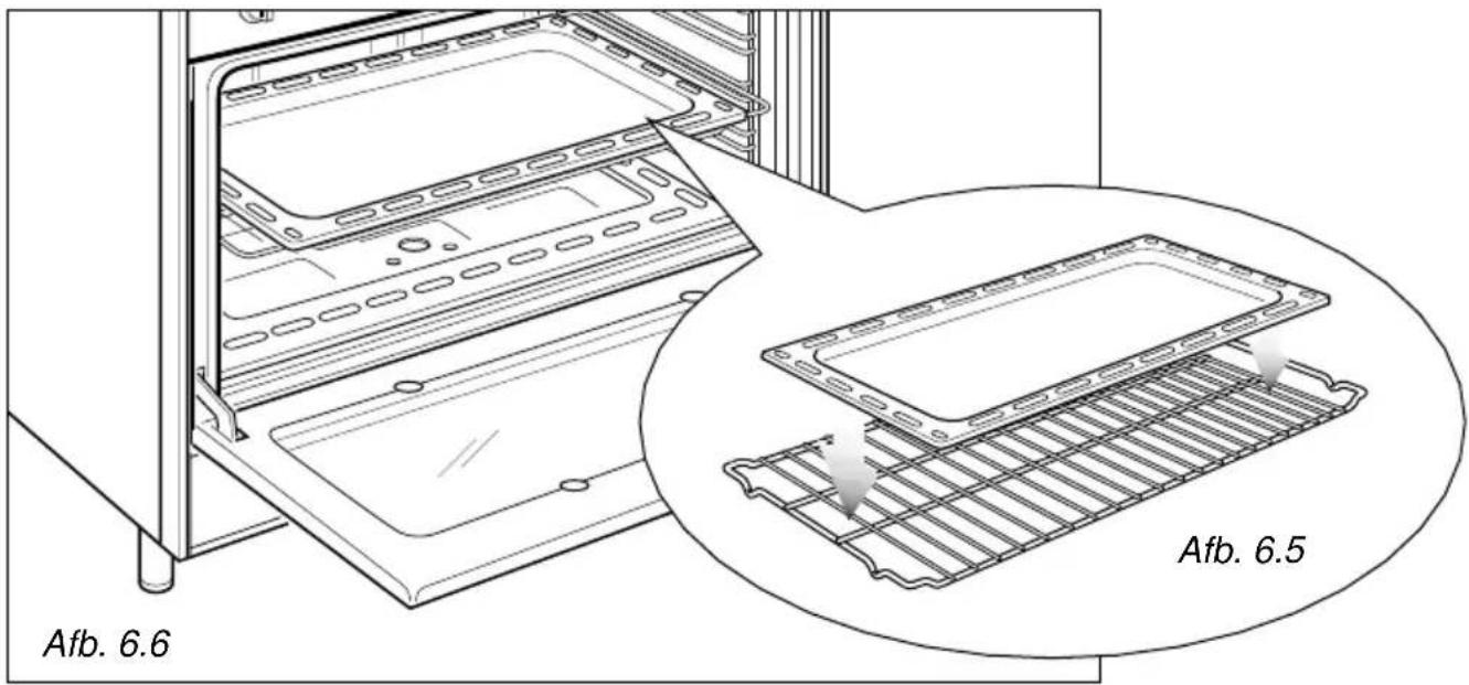
DEMONTAGE VAN DE OVENDEUR
natural_image
Technical line drawing of a mechanical bracket assembly (no text or symbols)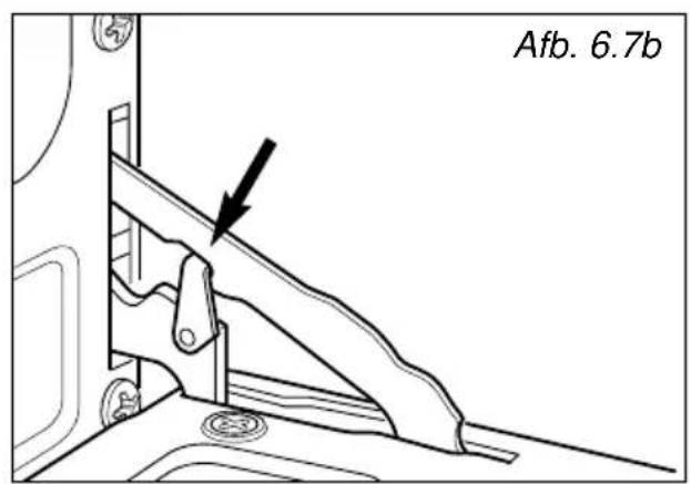
natural_image
Line drawing of hands installing or adjusting a rectangular panel on a door (no text or symbols)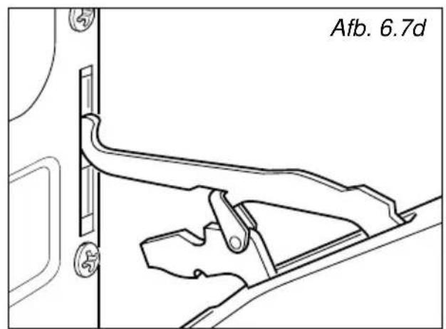
natural_image
Technical line drawing of a structural support frame with mounting holes and bolted joints (no text or symbols)DE VERSTELBARE VOETEN MONTEREN
natural_image
Line drawing of two people assembling a large oven on a tiled floor (no text or symbols)Afb. 7.4
natural_image
Line drawing of a person using a stove with a diagonal line crossing the floor, no text or symbols presentBEWEGINGSSYSTEEM VAN HET FORNUIS
WAARSCHUWING
Afb. 8.2
Afb. 8.3
natural_image
Simple line drawing of a trash bin with two crossed lines indicating no waste or prohibition (no text or symbols)
WICHTIGE HINWEISE
natural_image
Circular maze pattern with concentric rings and a central void, labeled 'Abb. 3.2' (no other text or symbols)DUO-SCHNELLKOCHZONE
natural_image
Abstract geometric pattern with concentric black and gray curved lines forming a spiral (no text or symbols)Abb. 3.4
Zweiten Kochzone
natural_image
Circular diagram with concentric black and gray spiral patterns, no text or symbols presentAbb. 3.5
natural_image
Illustration of a hand using a tool to brush or mark on a circular surface with scattered particles (no text or symbols)Abb. 3.8
(1 Segment = 1 Minute)
ZÄHLER
(1 Segment = 1 Minute)


Abb. 5.1
UHR (Abb. 5.2)
natural_image
Technical line drawing of a kitchen appliance with a tray and mounting base (no text or symbols)OFENTÜR
natural_image
Technical line drawing of a mechanical assembly with mounting feet and a bracket (no text or symbols)BACKOFEN
natural_image
Technical diagram of a mechanical assembly with spring-loaded components and directional arrows, labeled Abb. 6.3 (no text or symbols on the diagram itself)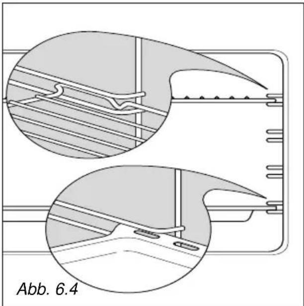
natural_image
Technical diagram showing two views of a mechanical component with internal channels and mounting holes (no text or symbols)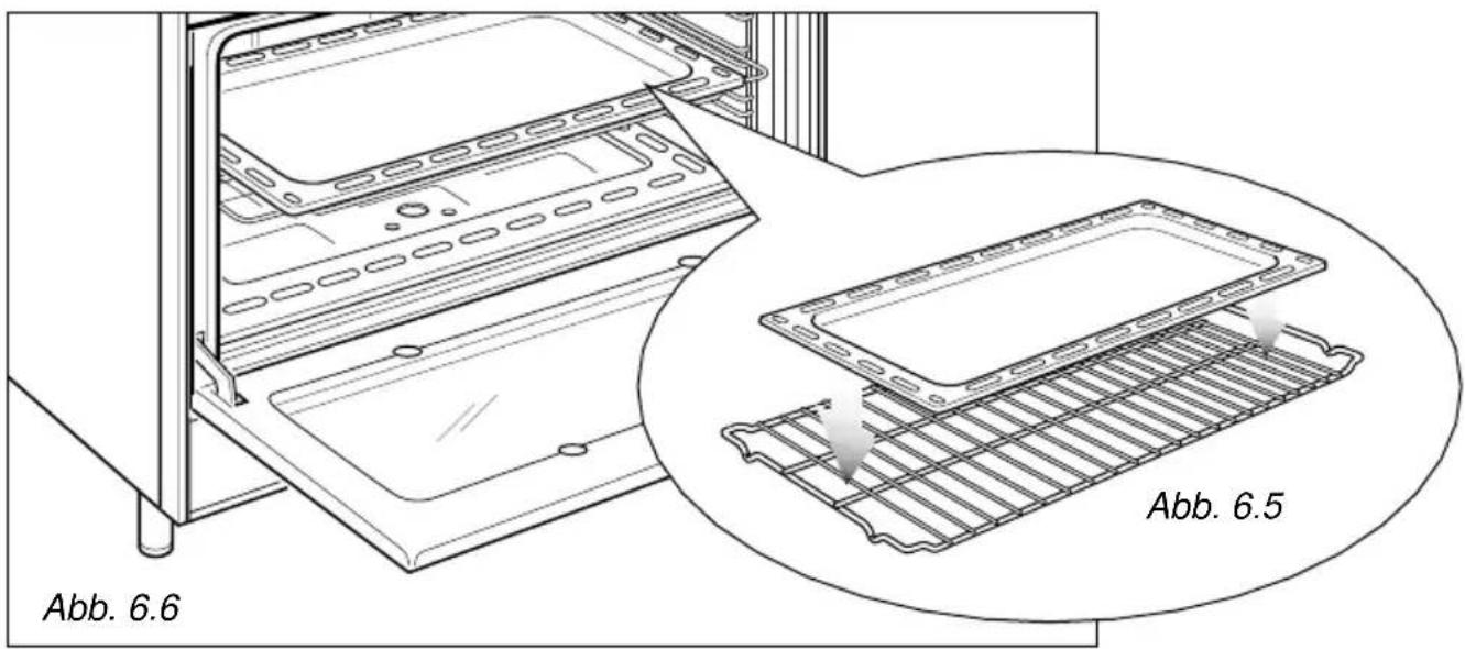
natural_image
Technical line drawing of a mechanical assembly with no visible text or symbols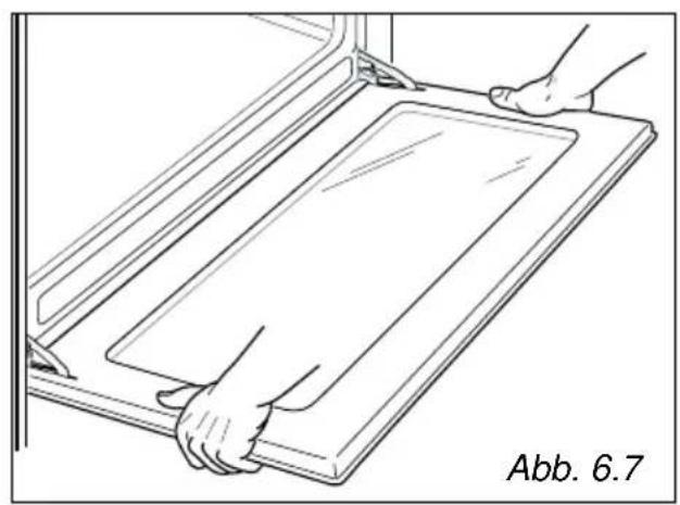
natural_image
Line drawing of hands installing or adjusting a rectangular panel on a cabinet (no text or symbols)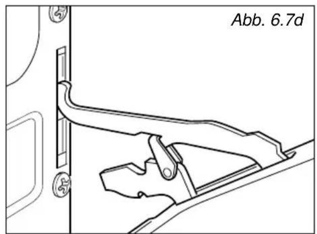
natural_image
Technical line drawing of a mechanical bracket or latch assembly (no text or symbols)Einbau-Anleitung
WICHTIG
natural_image
Technical line drawing of a mechanical assembly with mounting holes and structural supports (no text or symbols)natural_image
Line drawing of two people assembling a large oven on a tiled floor (no text or symbols)Abb. 7.4
natural_image
Line drawing of a person using a stove with a diagonal line crossing the stove (no text or symbols)KÜCHENHERD TRANSPORTIEREN
HINWEIS
N.B. For connection to the mains, do not use adapters, reducers or branching devices as they can cause overheating and burning.
If the installation requires alterations to the domestic electrical system or if the socket and appliance plug are incompatible, call an expert.
He should also check that the socket cable section is suitable for the power absorbed by the appliance.
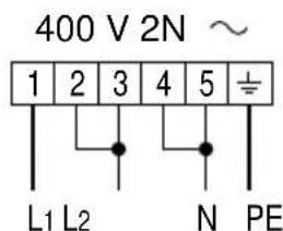
Abb. 8.2
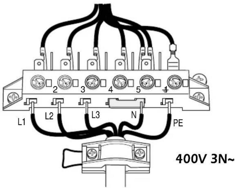
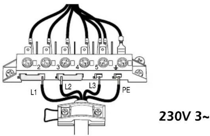
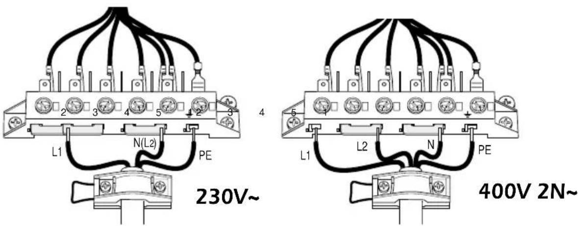
Abb. 8.3
Apreciado Cliente:
natural_image
Symbol of a trash bin crossed with a diagonal line and a horizontal bar below (no text or labels)natural_image
Circular maze pattern with concentric rings and a central void, labeled Fig. 3.2 (no text or symbols on the maze itself)ZONA RADIANTE DOUBLE Y OVAL
natural_image
Line drawing of a hand using a tool to brush or mark on a circular surface with scattered debris (no text or symbols)Fig. 3.8
4 - HORNO ELECTRICO MULTIFUNCION
Fig. 4.1
RELOJ (fig. 4.2)
natural_image
Line drawing of an open oven with a tray and mounting feet (no text or symbols)Fig. 6.1
PUERTA DEL HORNO
natural_image
Technical line drawing of a mechanical assembly with mounting feet and a vertical component (no text or symbols)Fig. 6.2
HORNO
natural_image
Technical line drawing of a door frame with coiled heating element and directional arrows indicating movement (no text or symbols)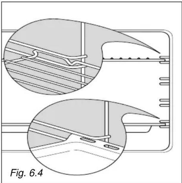
natural_image
Technical diagram showing two views of a mechanical component with internal structure and mounting holes (no text or symbols)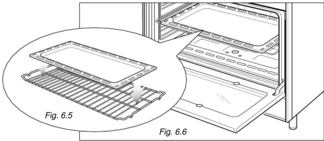
natural_image
Technical line drawing of a kitchen appliance with two views labeled Fig. 6.5 and Fig. 6.6, showing internal components without any text or symbols.natural_image
Technical line drawing of a mechanical bracket assembly (no text or symbols)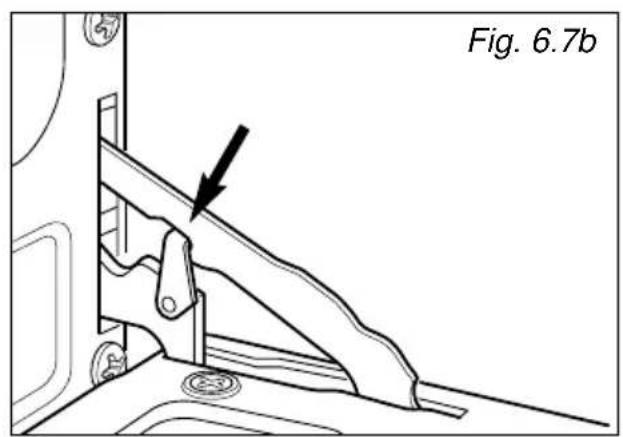
natural_image
Technical line drawing of a mechanical assembly with no visible text or symbols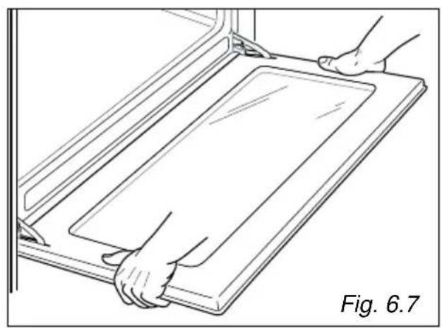
natural_image
Line drawing of hands installing or adjusting a rectangular panel on a shelf, labeled Fig. 6.7 (no text or symbols on the diagram itself)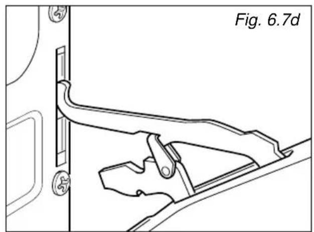
natural_image
Technical line drawing of a mechanical bracket or latch assembly (no text or symbols)natural_image
Technical line drawing of a structural assembly with mounting holes and supports (no text or symbols)MONTAJE DE LAS PATAS AJUSTABLES
natural_image
Line drawing of two people installing or adjusting a large oven on a tiled floor (no text or symbols)Fig. 7.4
natural_image
Line drawing of a person operating a large machine with a diagonal line crossing it, labeled Fig. 7.5 (no text or symbols on the diagram itself)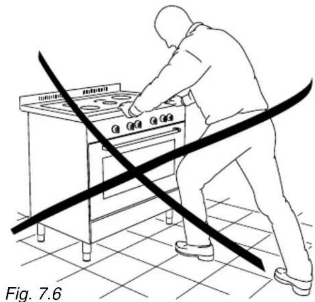
natural_image
Line drawing of a person using a stove with a diagonal line crossing the floor, labeled 'Fig. 7.6' (no text on diagram)CUIDADO:
natural_image
Diagram of a mechanical assembly with directional arrows indicating motion, labeled Fig. 7.7 (no text or symbols on diagram itself)8 - PARTE ELECTRICA
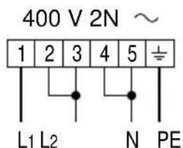
Fig. 8.2
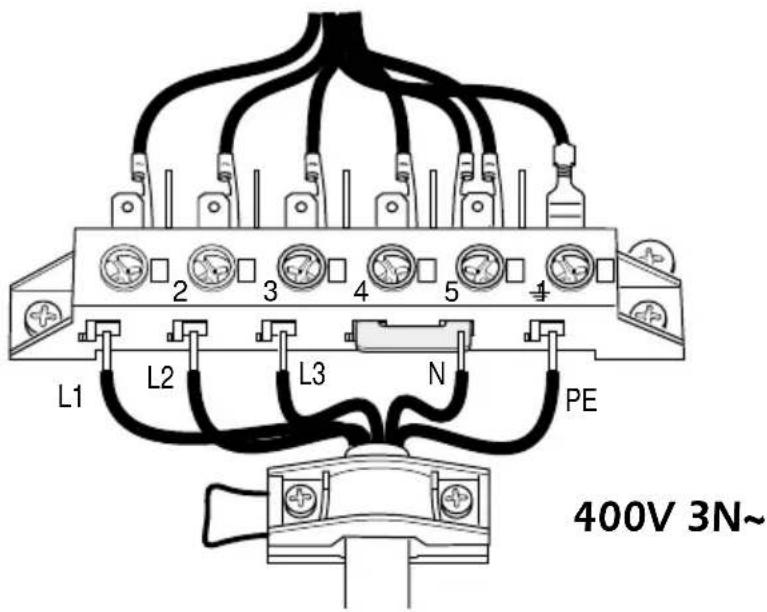
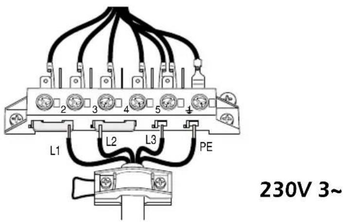
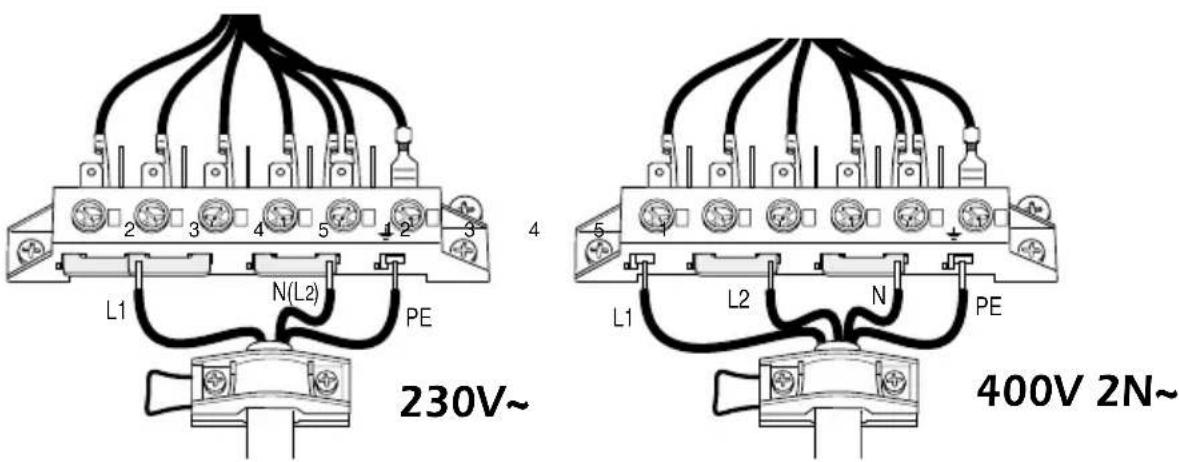
Fig. 8.3
Dear Customer,
Thank you for having purchased and given your preference to our product.
The safety precautions and recommendations given below are for your own safety and that of others. They will also provide a means by which to make full use of the features offered by your appliance.
Please keep this booklet carefully. It may be useful in future, either to yourself or to others if doubts should arise relating to its operation.
This appliance must be used only for the task it has explicitly been designed for, that is for cooking foodstuffs. Any other form of usage is to be considered as inappropriate and therefore dangerous.
The manufacturer declines all responsibility in the event of damage caused by improper, incorrect or unreasonable use of the appliance.
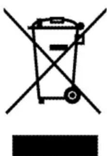
IMPORTANT INFORMATION FOR CORRECT DISPOSAL OF THE PRODUCT IN ACCORDANCE WITH EC DIRECTIVE 2002/96/EC.
At the end of its working life, the product must not be disposed of as urban waste. It must be taken to a special local authority differentiated waste collection centre or to a dealer providing this service.
Disposing of a household appliance separately avoids possible negative consequences for the environment and health deriving from inappropriate disposal and enables the constituent materials to be recovered to obtain significant savings in energy and resources. As a reminder of the need to dispose of household appliances separately, the product is marked with a crossed-out wheeled dustbin.
natural_image
Symbol of a trash bin crossed with a diagonal line and a horizontal bar below (no text or labels)USEFUL HINTS
After removing the appliance from its packing, make sure of its integrity.
In case of doubt, please apply to your supplier or to a qualified engineer.
The packing materials (plastic bags, polyfoam, nails, metal strips etc.) must be moved away from the reach of the children as potential sources of danger.
- Do not attempt to alter the technical features of the appliance as this may result very dangerous.
- Do not carry out any operation of cleaning or maintenance without prior disconnection of the appliance from the electric supply.
- Whenever you decide to get rid of this appliance (in case of replacement with a new one), before scrapping it is recommended to render it inoperative and harmless in respect of health and antipollution regulations.
IMPORTANT INSTRUCTIONS AND ADVICE FOR THE USE OF ELECTRICAL APPLIANCES
The use of any electrical appliance requires the compliance with some basic rules, namely:
- do not touch the appliance with wet or damp hands (or feet)
– do not use the appliance whilst in bare feet - do not allow the appliance to be operated by children or unqualified persons without supervision.
The manufacturer cannot be deemed responsible for damages caused by wrong or incorrect use.
FIRST USE THE OVEN
It is advised to follow these instructions:
- Clean the interior of the oven with cloth soaked in water and detergent (neutral) then dry carefully.
- Furnish the interior of the oven by placing the wire racks as described at chapter "Cleaning and maintenance".
- Insert shelves and tray.
- Empty the oven and close the door. Heat the oven at the maximum temperature setting for around two hours to eliminate the odour of grease and fumes from the manufacturing process. Make sure that the kitchen is well ventilated and do not remain in the room during this process.
This cooker has been designed, constructed and marketed in compliance with:
- safety requirements of EEC Directive "Low voltage" 73/23;
- protection requirements of EEC Directive "EMC" 89/336;
- requirements of EEC Directive 93/68.
IMPORTANT PRECAUTIONS AND RECOMMENDATIONS
- ATTENTION: please peel plastic cover of both sides and front before use.
- After use, ensure that the knobs are in "off" position.
- Do not allow children or other unqualified people to use the appliance without your supervision.
- During and after use of the cooker, certain parts will become very hot. Do not touch hot parts.
- Keep children well away from the appliance while it is in use.
- Some appliances are supplied with a protective film on steel and aluminium parts. This film must be removed before using the appliance.
- Fire risk! Do not store flammable material in the oven, above the glass ceramic hob and in the accessory drawer.
- Make sure that electrical cables connecting other appliances near the cooker cannot come into contact with the hob or be trapped in the oven door.
- Do not line the oven walls with aluminium foil. Do not place baking trays or the drip tray on the floor of the oven chamber.
- Do not allow heavy or sharp objects to drop on the glass ceramic hob. If the hob is cracked or otherwise damaged by falling objects etc., disconnect the electrical power cord and call Customer Service.
- Do not scratch the hob with sharp objects. Do not use the hob as a work surface.
-
Do not use a steam cleaner because the moisture can get into the appliance thus making it unsafe.
-
The manufacturer declines all liability for injury to persons or damage to property caused by incorrect or improper use of the appliance.
- The various components of the appliance are recyclable. Dispose of them in accordance with the regulations in force in your country. If the appliance is to be scrapped, cut off the power cord.
IMPORTANT:
This appliance is designed solely for the cooking of domestic food and is not suitable for commercial use.
This appliance incorporates a safety cooling fan which can be heard when the oven or grill are operating.
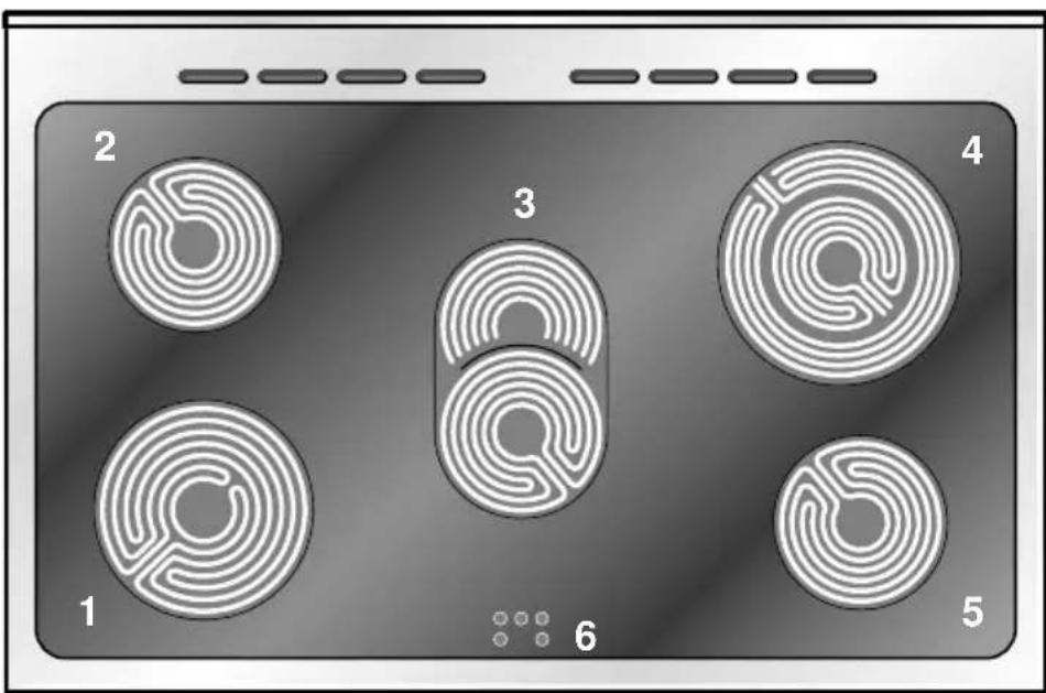
Fig. 1.1
VITROCERAMIC COOKING HOB
- 3 circuits cooking zone ∅ 180 1700 W
- 3 circuits cooking zone ∅ 145 1200 W
- Oval cooking zone ∅ 140 x 250 1800/1000 W
- Double cooking zone ∅ 210/120 2100/700 W
- 3 circuits cooking zone ∅ 145 1200 W
- Cooking zone residual heat indicators
Attention: Detach the appliance from the mains if the ceramic hobs is cracked.
2 - CONTROL PANEL
Fig. 2.1
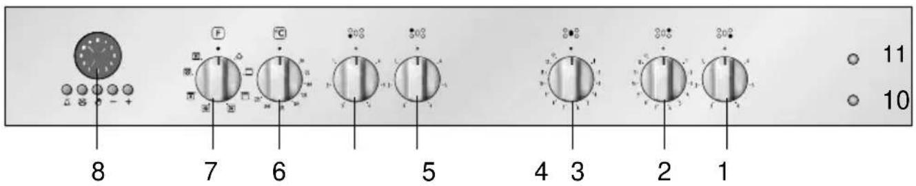
CONTROL PANEL - Controls description
- Front right cooking zone control knob
- Rear right cooking zone control knob
- Central cooking zone control knob
- Rear left cooking zone control knob
- Front left cooking zone control knob
- Multifunction oven thermostat knob
- Multifunction oven switch knob
- Electronic clock/programme
Pilot lamps:
- Oven thermostat indicator light
- Cooking hob ON indicator light
3 - USE OF COOKING HOB
The ceramic surface of the hob allows a fast transmission of heat in the vertical direction, from the heating elements underneath the ceramic glass to the pans set on it.
The heat does not spread in the horizontal direction, so that the glass stays "cool" at only a few centimeters from the cooking plate.
The 5 cooking zones are shown by dark disks on the ceramic surface.
IMPORTANT NOTE:
The heating elements incorporate a thermolimiter that switches ON/OFF the element in all settings to protect any overheating of the ceramic glass.
The use of incorrect pans and/or wrong pan positioning will cause the temperature limiter to operate more frequently, resulting in a reduction of cooking performance.
3 CIRCUITS RADIANT ZONES
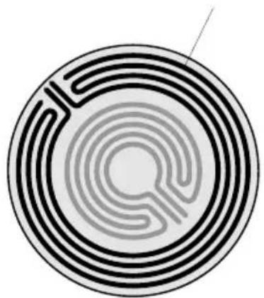
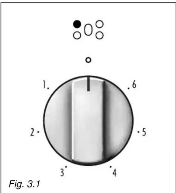
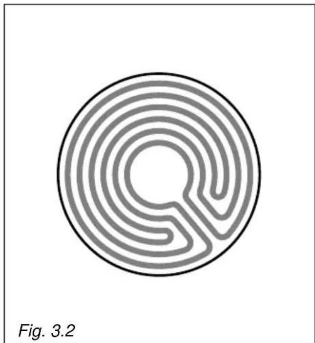
Incorporating 3 heating elements (fig. 3.2) you can control and light up all together or separately by a 6 position switch (fig. 3.1).
Reaches the working temperature in a very short time.
natural_image
Circular maze pattern with concentric rings and a central oval, labeled Fig. 3.2 (no text or symbols on the maze itself)DOUBLE AND OVAL RADIANT ZONES
The heating element is formed of a coil of resistant material which reaches the working temperature quickly.
Operation of the cooking zone is controlled by a continuous energy regulator from "1" to "12" (maximum temperature) (fig. 3.3).
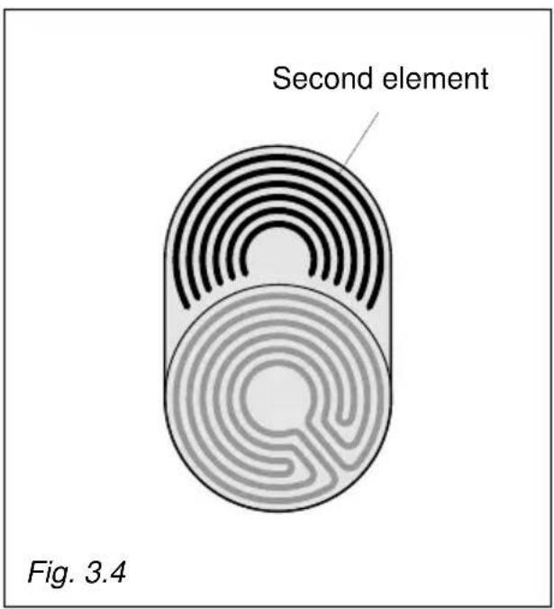
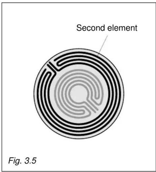
By switching on the second element (fig. 3.4 and 3.5), the surface area of the rear right and central radiant zones can be extended.
For this purpose, turn the control knob (fig. 3.3) fully to the right (position ⊙).
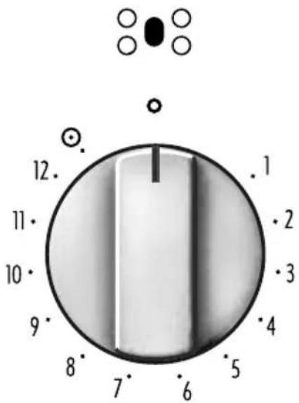
Fig. 3.3
Cooking plate controlled by a 7 position switch
Cooking plate controlled by a 12 position switch
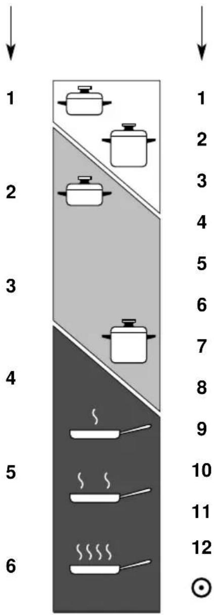

Heating

Cooking

Roasting-frying
Fig. 3.6
COOKING HINTS
| Knob setting | TYPE OF COOKING | |
| 0 | 0 | Switched OFF |
| 12 | 12 | For melting operations (butter, chocolate). |
| 2 | 234 | To maintain food hot and to heat small quantities of liquid (sauces, eggs). |
| 3 | 456 | To heat bigger quantities; to whip creams and sauces. (vegetables, fruits, soups). |
| 34 | 67 | Slow boiling, i.e.: boiled meats, spaghetti, soups, continuations of steam cooking of roasts, stews, potatoes. |
| 4 | 78 | For every kind of frying, cutlets, uncovered cooking, i.e.: risotto. |
| 45 | 8910 | Browning of meats, roasted potatoes, fried fish, omelettes, and for boiling large quantities of water. |
| 6 | 1112 | Fast frying, grilled steaks, etc. |
| ◎ | Switching on the second element (Double and oval radiant plate only) | |
After a short period of use, experience will teach you which setting is the right one for your needs.
RESIDUAL HEAT INDICATOR
The hob also features 5 warning lamps which are wired to the corresponding plate.
When the temperature of a cooking plate is over 60^ C, the relevant warning lamp is also lit-up to warn of heat on the surface of the hob.
This lamp also stay on after the cooking plate has been switched off to shown that the hob surface is still hot.
This residual heat lasts for a rather long time after the cooking plate has been switched off.
During this period of time you should avoid touching the hob surface over the cooking area.
Please pay special attention to ensuring children are not allowed near the hob.
The lamp will switch off automatically as soon as the surface temperature of the cooking plate falls below 60^ C.
Caution!
the cooking hob becomes very hot during operation.
Keep children well out of reach.
Cooking hints:
- To reduce the cooking time, you can turn the control knob to the max when you switch the plate on.
After a short time you will set the control knob to the required position for the cooking. - You should use pots and pans with flat bases (pans with the test mark for glass-ceramic hobs are available from specialist shops).
The diameter of the pan should match that of the cooking plate (or be slightly bigger) to make the most of the energy. - Since the cooking surface stays hot for a certain time after the plate has been switched off, you can switch it off 5 or 10 minutes before the end of the cooking.
The residual heat of the hob will complete the cooking. - To save electricity, use pan lids whenever possible.
- Never cook the food directly on the glass ceramic cooktop, but in special pans or containers.
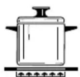
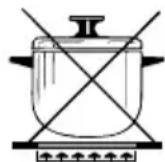
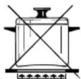
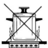
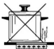
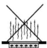
Fig. 3.7
ADVICE FOR SAFE USE OF THE COOKTOP
- Before switching on make sure that you have the correct knob for the hotplate chosen. It is advisable to put the pan on the hotplate before switching on and to take it away after switching off.
- Use cookware with flat and even bottoms (be careful when using cast iron vessels). Uneven bottoms can scratch the glass ceramic surfaces. Be careful that the bottom is clean and dry.
- Pots with aluminium bottoms may leave silver streaks or spots on the bob.
- Do not leave wet or damp lids on the bob.
- The glass-ceramic surface and pans must be clean. Carefully eliminate any food remains (especially containing sugar), dirt etc. with the aid of a cleansing agent.
- Make sure that the handles of cookware do not stick out over the edge of the cooker, to avoid them being knocked over by accident. This also makes it more difficult for children to reach the cooking vessels.
- Do not lean over the cooking zones when they are switched on.
- Do not drop heavy or sharp objects on the glass ceramic cooktop. If the surface is broken or damaged unplug the cooktop and contact the after-sales service.
- Do not put aluminium foil or plastic objects on the cooking zones when they are hot.
- Remember that the cooking zones remain hot for some time after they are switched off (about 30 mm.).
- Follow the cleaning instructions carefully.
- If you note a crack in the cooktop, switch the appliance off immediately and call the After-Sales Service.
Do not scratch the cooktop with cutting or sharp objects.
Do not use the glass ceramic surface as a work surface.
CLEANING
Before you begin cleaning make sure that the appliance is switched off.
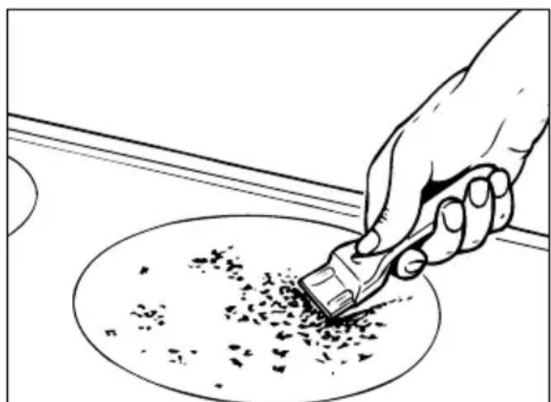
Remove any encrustation using the scraper provided.
Dust or food particles can be removed with a damp cloth.
If you use a detergent, please make sure that it is not abrasive or scouring. Abrasive or scouring powders can damage the glass surface of the hob.
All traces of the cleaner have to be removed with a damp cloth.
It is highly recommended to keep off the hob any article which can melt: plastic, aluminium foil, sugar, sugar syrup mixtures etc.
If any of these products has melted on the ceramic surface, you should remove it immediately (when the surface is still hot) by using the scraper to avoid any permanent damage to the surface of the hob.
Avoid using any knife or sharp utensil since these can damage the ceramic.
Do not use steel wool or an abrasive sponge which could scratch the surface in an irreparable way
ATTENTION: MOST IMPORTANT!
If cleaning the glass ceramic hob using a special tool (i.e. scraper) take extra care to avoid damage to the seal at the edges of the glass ceramic surface.
natural_image
Line drawing of a hand using a tool to brush or scrape material over a circular surface (no text or symbols)Fig. 3.8
4 - MULTI-FUNCTION OVEN
Attention: the oven door becomes very hot during operation.
Keep children away.
GENERAL FEATURES
As its name indicates, this is an oven that presents particular features from an operational point of view.
In fact, it is possible to insert 7 different programs to satisfy every cooking need.
The 7 positions, thermostatically controlled, are obtained by 4 heating elements which are:
- Bottom element 1725 W
- Top element 1725 W
- Grill element 2500 W
– Circular element 2500 W - Fan motor 25 W
- Oven lamp 15 W
NOTE:
Upon first use, it is advisable to operate the oven for 30 minutes in the position and for another 30 minutes at the maximum temperature (thermostat knob on position 225) in the positions and, to eliminate possible traces of grease on the heating elements.
Clean the oven and accessories with warm water and washing-up liquid.
WARNING:
The door is hot, use the handle.
OPERATING PRINCIPLES
Heating and cooking in the MULTI-FUNCTION oven are obtained in the following ways:
a. by normal convection
The heat is produced by the upper and lower heating elements.
b. by forced convection
A fan sucks in the air contained in the oven muffle, which sends it through the circular heating element and then sends it back through the muffle. Before the hot air is sucked back again by the fan to repeat the described cycle, it envelops the food in the oven, provoking a complete and rapid cooking.
It is possible to cook several dishes simultaneously.
c. by semi-forced convection
The heat produced by the upper and lower heating elements is distributed throughout the oven by the fan.
d. by radiation
The heat is irradiated by the infra red grill element.
e. by radiation and ventilation
The irradiated heat from the infra red grill element is distributed throughout the oven by the fan.
f. by ventilation
The food is defrosted by using the fan only function without heat.
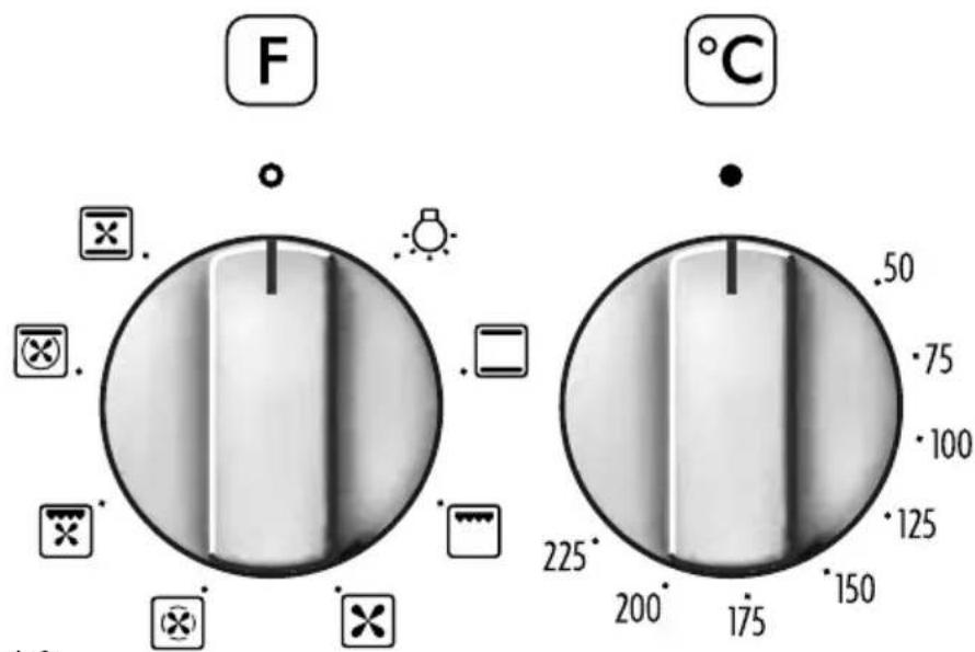
Fig. 4.1 Fig. 4.2
THERMOSTAT KNOB (Fig. 4.2)
To turn on the heating elements of the oven, set the switch knob on the desired program and the thermostat knob onto the desired temperature.
To set the temperature, it is necessary to make the knob indicator meet the chosen number.
The elements will turn ON or OFF automatically according to the energy need which is determined by the thermostat.
FUNCTION SELECTOR KNOB (Fig. 4.1)
Rotate the knob clockwise to set the oven for one of the following functions:

OVEN LIGHT
By turning the knob onto this setting we light the oven cavity (15 W).
The oven remains alight while any of the functions is on.

TRADITIONAL CONVECTION COOKING
The upper and lower heating elements are switched on. The heat is diffused by natural convection and the temperature must be regulated between 50^ and 225^ with the thermostat knob.
It is necessary to preheat the oven before introducing the foods to be cooked.
Recommended for:
For foods which require the same cooking temperature both internally and externally, i.e. roasts, spare ribs, meringue, etc.

GRILLING
The infra-red heating element is switched on. The heat is diffused by radiation.
Use with the oven door closed and the thermostat knob to between 50^ and 225^ C for max 15 minutes, then to position 175^ C.
Note: It is recommended that you do not grill for longer than 30 minutes at any one time.
Attention: the oven door becomes very hot during operation. Keep children away.
For correct use see chapter "USE OF THE GRILL"
Recommended for:
Intense grilling action for cooking with a broiler; browning, crisping, "au gratin", toasting, etc.

DEFROSTING FROZEN FOODS
Only the oven fan is on. To be used with the thermostat knob on “●” because the other positions have no effect. The defrosting is done by simple ventilation without heat.
Recommended for:
To rapidly defrost frozen foods; 1 kilogram requires about one hour.
The defrosting times vary according to the quantity and type of foods to be defrosted.

HOT AIR COOKING
The circular element and the fan are on. The heat is diffused by forced convection and the temperature must be regulated between 50^ and 225^ C with the thermostat knob. It is not necessary to preheat the oven.
Recommended for:
For foods that must be well done on the outside and tender or rare on the inside, i. e. lasagna, lamb, roast beef, whole fish, etc.

VENTILATED GRILL COOKING
The infra-red ray grill and the fan are on. The heat is mainly diffused by radiation and the fan then distributes it throughout the oven. The temperature must be regulated between 50° and 175 °C for max 30 minutes, with the thermostat knob. It is necessary to preheat the oven for about 5 minutes.
Use with the oven door closed.
Attention: the oven door becomes very hot during operation.
Keep children away.
For correct use see chapter "GRILLING AND "AU GRATIN".
Recommended for:
For grill cooking when a fast outside browning is necessary to keep the juices in, i. e. veal steak, steak, hamburger, etc.

THAWING AND WARMING UP
The upper element and the circular element connected in series, are switched on; also the fan is on. The heat is diffused by forced convection with the most heat being produced by the upper element.
The temperature must be regulated between 50° and 140 °C with the thermostat knob.
Recommended for:
To keep foods hot after cooking. To slowly heat already cooked foods.

CONVECTION COOKING WITH VENTILATION
The upper and lower heating elements and the fan turn on.
The heat coming from the top and bottom is diffused by forced convection.
The temperature must be regulated between 50° and 225 °C with the thermostat knob.
Recommended for:
For foods of large volume and quantity which require the same internal and external degree of cooking; for ie: rolled roasts, turkey, legs, cakes, etc.
COOKING ADVICE STERILIZATION
Sterilization of foods to be conserved, in full and hermetically sealed jars, is done in the following way:
a. Set the switch to position
b. Set the thermostat knob to position 185 °C and preheat the oven.
c. Fill the dripping pan with hot water.
d. Set the jars onto the dripping pan making sure they do not touch each other and the door and set the thermostat knob to position 135 °C.

When sterilization has begun, that is, when the contents of the jars start to bubble, turn off the oven and let cool.
REGENERATION
Set the switch to position and the thermostat knob to position 150°C.
Bread becomes fragrant again if wet with a few drops of water and put into the oven for about 10 minutes at the highest temperature.
ROASTING
To obtain classical roasting, it is necessary to remember:
- that it is advisable to maintain a temperature between 180 and 200^ .
– that the cooking time depends on the quantity and the type of foods.
SIMULTANEOUS COOKING OF DIFFERENT FOODS
The MULTI-FUNCTION oven set on position ✕ and ✗ gives simultaneous heterogeneous cooking of different foods. Different foods such as fish, cake and meat can be cooked together without mixing the smells and flavours.
This is possible since the fats and vapors are oxidized while passing through the electrical element and therefore are not deposited onto the foods.
The only precautions to follow are:
- The cooking temperatures of the different foods must be as close to as possible, with a maximum difference of 20^ - 25^ .
- The introduction of the different dishes in the oven must be done at different times in relation to the cooking times of each one.
The time and energy saved with this type of cooking is obvious.
GRILLING AND "AU GRATIN"
Set the switch to position

Set the thermostat to position 175 °C and after having preheated the oven, simply place the food on the shelf.
Close the door and let the oven operate with the thermostat on, until grilling is complete.
Adding a few dabs of butter before the end of the cooking time gives the golden “au gratin” effect.
Note: It is recommended that you do not grill for longer than 30 minutes at any one time.
ATTENTION: the oven door becomes very hot during operation.
Keep children away.
USE OF THE GRILL
Preheat the oven for about 5 minutes.
Introduce the food to be cooked, positioning the rack as close to the grill as possible.
The dripping pan should be placed under the rack to catch the cooking juices and fats.
Grilling with the oven door closed.
Do not grill for longer than 30 minutes at any one time.
CAUTION: the oven door becomes very hot during operation. Keep children well out of reach.
OVEN COOKING
Before introducing the food, preheat the oven to the desired temperature.
For a correct preheating operation, it is advisable to remove the tray from the oven and introduce it together with the food, when the oven has reached the desired temperature.
Check the cooking time and turn off the oven 5 minutes before the theoretical time to recuperate the stored heat.
COOKING EXAMPLES
Temperatures and times are approximate as they vary depending on the quality and amount of food.
Remember to use ovenproof dishes and to adjust the oven temperature during cooking if necessary.
DISHES TEMPERATURE
Cakes 180°
Doughnuts 180°
Cheese soufflé 200°
Potatoes in milk 200°
Chicken breasts in tomato 200°
Sole fish filet 200°
Whiting 200°
Cream puffs 200°
Plum pie 200°
Meat balls 200°
Veal meatloaf 200°
Grilled chicken - roast chicken 220°
Baked lasagna 220°
Roast beef 220°
Oven cooked pasta 220°
Lemon cake 220°
Rice creol 225°
Baked onions 225°
Stuffed potatoes 225°
Grilled veal joint 225°
Marmalade pie 225°
Pound cake 225°
Turkish shishkebab 250°
Pizza with anchovies 250°
5 - ELECTRONIC CLOCK/PROGRAMME
The electronic clock/programmer performs the following functions ("one-hand" operation):
- 12 hours clock with luminous hands (hours, minutes and seconds).
- Timer (up to 60 minutes).
- Automatic cooking program. The oven starts to operate at the programmer time (within 12 hours when the oven is programmed) and automatically switches off at the end of the programmed required time (max 6 hours).
- Semi-automatic cooking program. The oven automatically switches off at the end of the programmed cooking time (max 6 ore).
Buttons description:

Timer

Cooking time/End of cooking time (hour)

Clock setting/Cancelling a set program

To increase (clockwise rotation of the clock/programmer hands)

To decrease (anti-clockwise rotation of the clock/programmer hands)
Note: To set the clock/programmer ("one-hand operation) press the relative function button and then, within 7 seconds, press the or buttons.
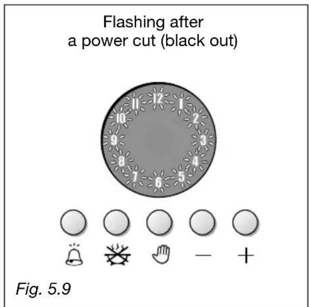
After a power cut (black out) the display resets to zero and cancels the set programs.
CLOCK:
Minutes luminous hands
Hours luminous hands
Second luminous hands
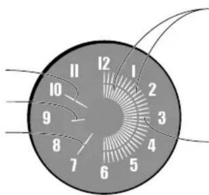
AUTOMATIC OR
Inner luminous hands
(1 hand = 12 minutes)
Outer luminous hands
(1 hand = 1 minute)
TIMER
Outer luminous hands
(1 hand = 1 minute)


Fig. 5.1
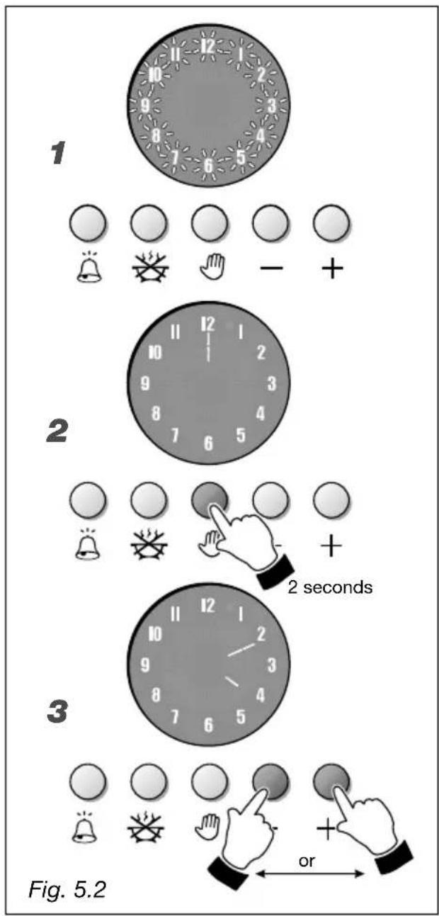
CLOCK (fig. 5.2)
- Fig. 5.2 - Upon immediate connection of the oven or after a power cut (black out), the numbers on the programmer display will flash.
- Fig. 5.2 - To set the time, press button 🤨 for about one second; one hand appears on 12.
- Fig. 5.2 - Within 7 seconds press + or buttons to set the time of the day (hours and minutes). Seven seconds after the last selection, the seconds hand appears on the display.
Note: If the clock is reset it deletes any previously set program.
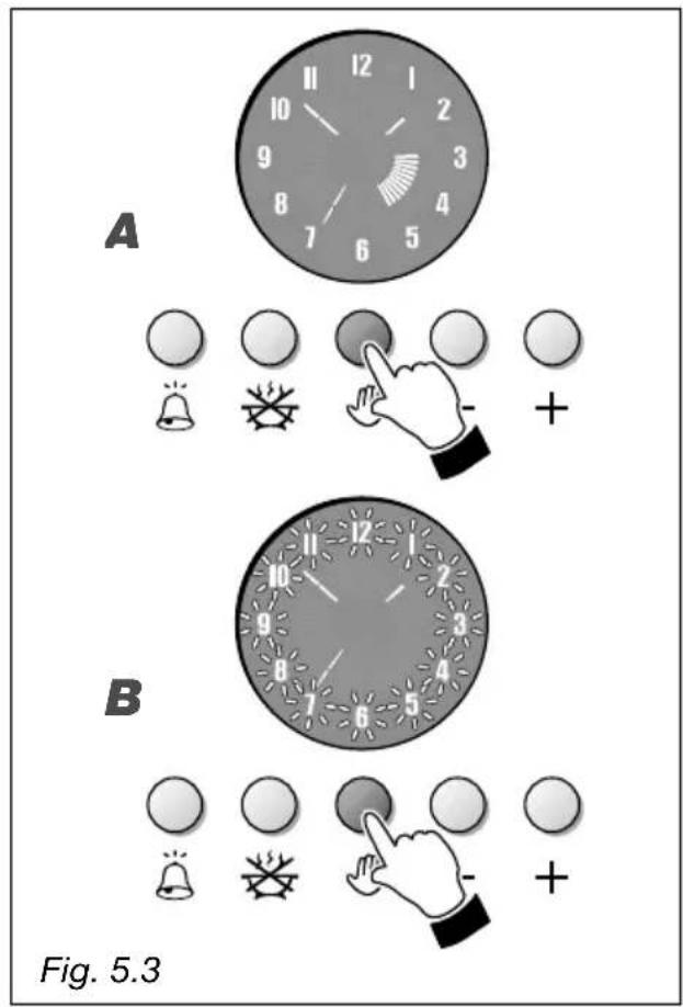
MANUAL COOKING WITHOUT PRO- GRAMMER (fig. 5.3)
To manually use the oven, without the programmer, the numbers on the display do not have to flash and the inner hands do not have to be lit (none semi-automatic or automatic program set).
A. Fig. 5.3 - Programmer with a set program. To cancel the set program press button for about 2 seconds; inner hands disappears on the display and the oven can be used in manual mode.
B. Fig. 5.3 - Flashing numbers on the display (normally after turning off the buzzer which indicates the end of a programmed cooking).
Press button. The numbers stop flashing and the oven can be used in manual mode.
Attention: At the end of the cooking switch off the oven manually by turning the function and temperature control knobs to the "0" (OFF) position.
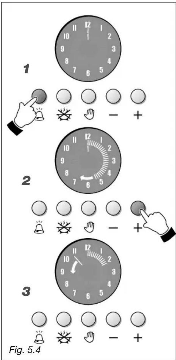
TIMER (fig. 5.4)
The timer program consists only of a buzzer which may be set for a maximum period of 60 minutes.
- Fig. 5.4 - To set the timer program press 🔒 button.
- Fig. 5.4 - Press button Ⓢ within 7 seconds and set the required time. Outer luminous hands light up. Press button to decrease the time.
- Fig. 5.4 - The countdown starts immediately and an anti-clockwise luminous hand lights up on the display. On each rotation (1 minute) of this hand one outer luminous hand goes out.
During the countdown it is possible, at any time, to change the setting by pressing button or ; to reset the timer press button until reaching zero minutes (none outer luminous hand lit).
At the end of the time, the last outer luminous hand goes out and the buzzer sounds. To stop the buzzer press any of the clock/programmer buttons. The display shows the time of the day.
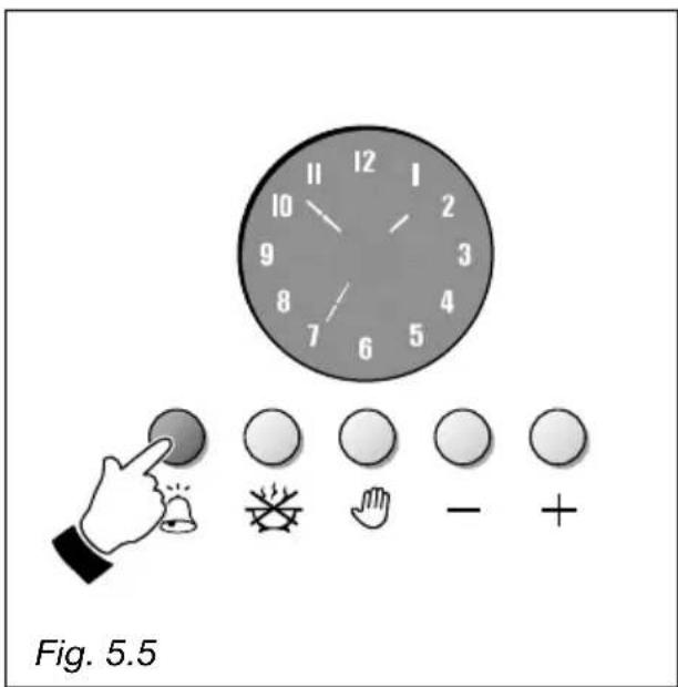
To display the time of the day during the countdown, press button (fig. 5.5); to display the countdown again press button ☑.
Note: the timer can be set also if a semi-automatic or automatic cooking program is operating.
ATTENTION: The timer do not switches off the oven at the end of the count-down. Remember to switch off the oven manually by turning the function and temperature control knobs the "0" (OFF) position.
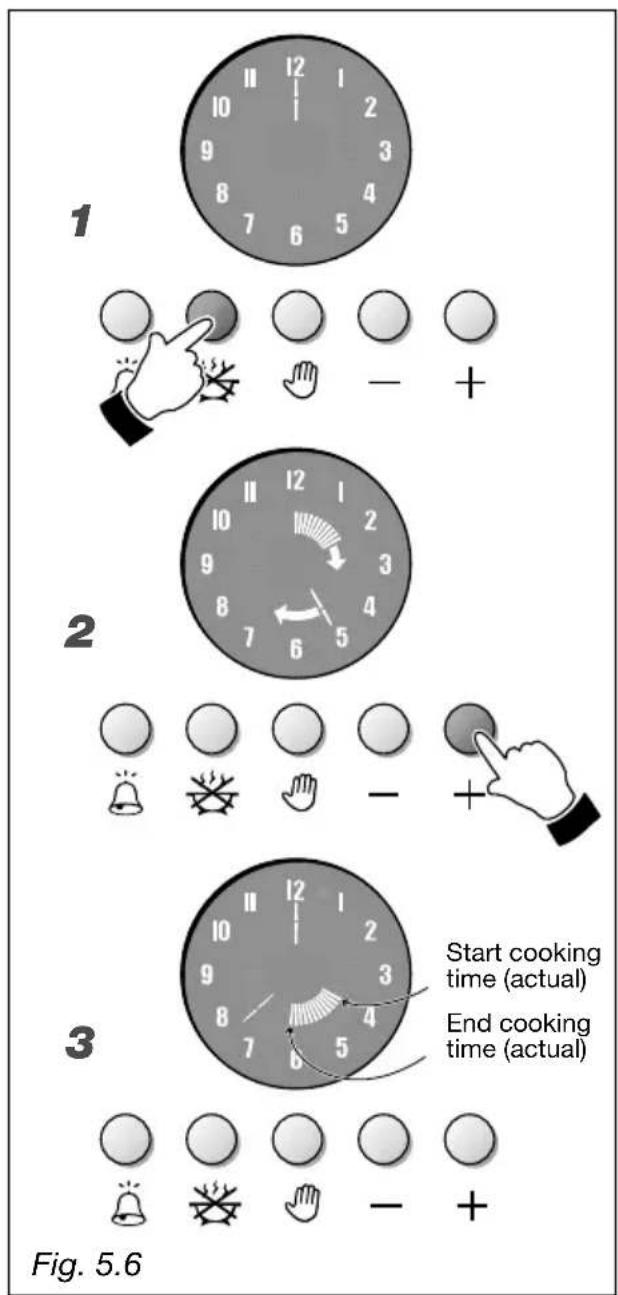
SEMI-AUTOMATIC COOKING (fig. 5.6)
This function automatically switches off the oven after the required cooking time.
- Fig. 5.6 - To set the cooking time (max 6 hours) press button ☑ the electronic clock luminous hands go out and a luminous hand lights up on number 12.
- Fig. 5.6 - Within 7 seconds press + button and another luminous hand (like seconds and minutes) lights up on the display. Every increasing (additional inner hand) indicates one minute. Moreover every increasing of the 12 minutes is indicated by an inner luminous hand (5 luminous hands indicate one hour). To decrease the required time press button.
- Fig. 5.6 - After 7 seconds the inner luminous hands turn automatically on the time of the day indicating the remaining cooking time.
- Set the oven by turning the function and the temperature control knobs to the required function and temperature (see relative chapters). The oven starts to operate immediately and is automatically turned off at the end of the programmed cooking time.
During cooking the inner luminous hands flash on the display indicating that the oven is operating. The inner luminous hands gradually go out (one each 12 minutes).
During the cooking program it is possible, at any time, to modify the cooking time by pressing first button and then + or - .
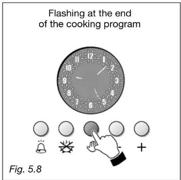
At the end of the programmed cooking time the last inner luminous hand goes out and the oven automatically switches off; the numbers on the programmer display flash and a buzzer sounds.
To stop the buzzer press any of the clock/programmer buttons.
To stop the flashing of the numbers of the clock press button.
The semi-automatic cooking program can be cancelled at any time by pressing button for 2 seconds.
ATTENTION: At the end of the semi-automatic cooking remember to switch off the oven manually by turning the function and temperature control knobs the "0" (OFF) position.
Attention: After a power cut (black out) the clock/programmer resets to zero and cancels the set programs (numbers of the clock flashing on the display without luminous hands - fig. 5.9).
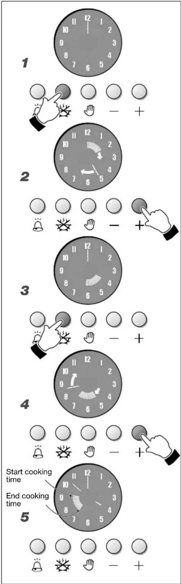
AUTOMATIC COOKING (fig. 5.7)
This function automatically switches on the oven and switches it off at the required time. To cook the food in the automatic mode follow these instructions:
- Set the duration of the cooking (max 6 hours)
- Set the time when cooking has to be completed (within 12 hours from when the cooking is programmed)
- Set the cooking temperature and function.
For the automatic cooking operate in the following way:
-
Fig. 5.7 - To set the cooking time (max 6 hours) press button ☑ the electronic clock luminous hands go out and a luminous hand lights up on number 12.
-
Fig. 5.7 - Within 7 seconds press + button and another luminous hand (like seconds and minutes) lights up on the display. Every increasing (additional inner hand) indicates one minute. Moreover every increasing of the 12 minutes is indicated by an inner luminous hand (5 luminous hands indicate one hour). To decrease the required time press button.
-
Fig. 5.7 - Within 7 seconds press another time button; the inner luminous hands turn automatically on the time of the day.
-
Fig. 5.7 - Within 7 seconds press + button and position (by pressing the button) the inner luminous hands on the hour when the oven has to start the cooking program. Press button to decrease.
-
Fig. 5.7 - After 7 seconds the clock luminous hands appear again on the display and the inner luminous hands indicate the programmed cooking time.
-
Set the oven by turning the function and the temperature control knobs to the required function and temperature (see relative chapters). Now the oven is programmed and it starts and stops to operate automatically, conforming to the automatic cooking program.
When the oven starts the cooking program the inner luminous hands are flashing on the display indicating that the oven is operating and they gradually go out (one each 12 minutes).
During the cooking program it is possible, at any time, to modify the cooking time by pressing first button and then + or - .
At the end of the programmed cooking time the last inner luminous hand goes out and the oven automatically switches off; the numbers on the programmer display flash and a buzzer sounds.
To stop the buzzer press any of the clock/programmer buttons.
To stop the flashing of the numbers of the clock press button.
The automatic cooking program can be cancelled at any time by pressing 🤒 button for 2 seconds.
ATTENTION: At the end of the automatic cooking remember to switch off the oven manually by turning the function and temperature control knobs the "0" (OFF) position.
Attention: After a power cut (black out) the clock/programmer resets to zero and cancels the set programs (numbers of the clock flashing on the display without luminous hands - fig. 5.9).
6 - CLEANING AND MAINTENANCE
Important:
Before any operation of cleaning and maintenance disconnect the appliance from the electrical supply and wait for it to cool down.
Attention
The appliance gets very hot, mainly around the cooking areas. It is very important that children are not left alone in the kitchen when you are cooking.
Do not use a steam cleaner because the moisture can get into the appliance thus make it unsafe.
ENAMELLED PARTS
All the enamelled parts must be cleaned with a sponge and soapy water or other non-abrasive products.
Dry preferably with a soft cloth.
Acidic substances like lemon juice, tomato sauce, vinegar etc. can damage the enamel if left too long.
STAINLESS STEEL SURFACES
The stainless steel front panels on this cooker (facia, oven door, drawer or storage compartment) are protected by a finger-print proof lacquer.
To avoid damaging this lacquer, do not clean the stainless steel with abrasive cleaners or abrasive cloths or scouring pads.
ONLY SOAP/WARM WATER MUST BE USED TO CLEAN THE STAINLESS STEEL SURFACES.
VITROCERAMIC COOKING HOB
- See page 108.
REPLACING THE OVEN LIGHT BULB
Switch the cooker off at the mains. When the oven is cool, unscrew and replace the bulb with another one resistant to high temperatures (300°C), voltage 230 V (50 Hz), 15 W, E14.
Note: Oven bulb replacement is not covered by your guarantee.
natural_image
Line drawing of an open oven with a tray and mounting feet (no text or symbols)Fig. 6.1
OVEN DOOR
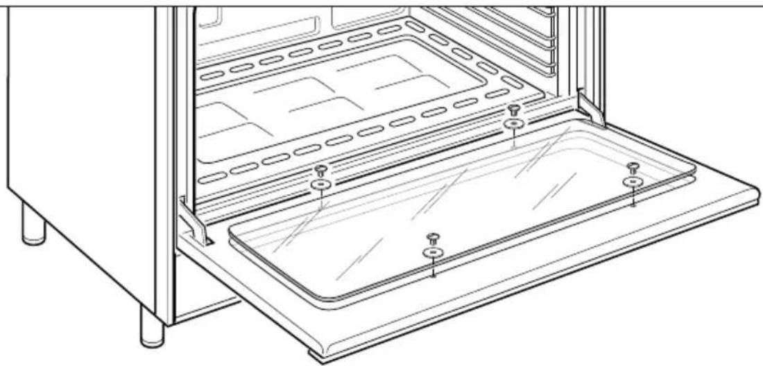
The internal glass panel can be easily removed for cleaning by unscrewing the 2 retaining screws (Fig. 6.1)
STORAGE COMPARTMENT
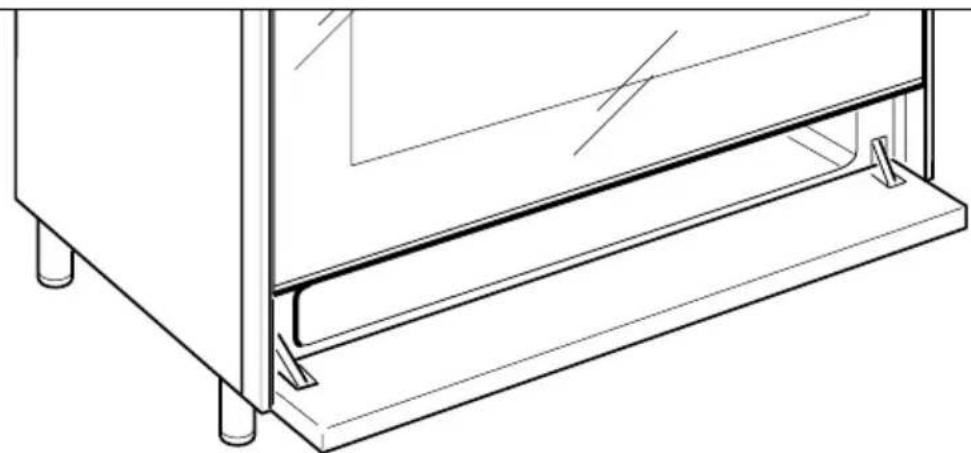
The storage compartment is accessible through the pivoting panel (fig. 6.2).
Do not store flammable material in the oven or in the storage compartment.
natural_image
Technical line drawing of a cabinet or enclosure with mounting feet and a horizontal shelf (no text or symbols)Fig. 6.2
INSIDE OF OVEN
This must be cleaned regularly.
Remove and refit the side runner frames as described on the next chapter.
With the oven warm, wipe the inside walls with a cloth soaked in very hot soapy water or another suitable product. Side runner frames, tray, lower panel and rack can be removed and washed in the sink.
ASSEMBLY AND DISMANTLING OF THE SIDE RUNNER FRAMES
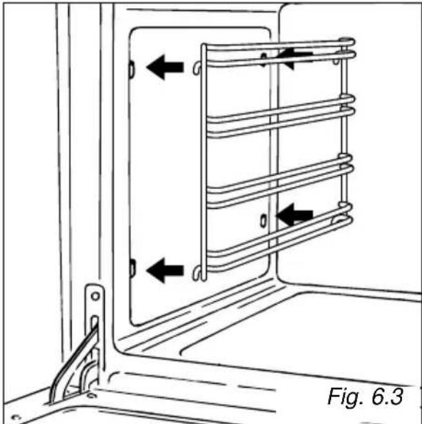
- Fit the side runner frames into the holes on the side walls inside the oven (Fig. 6.3).
- Slide the tray and rack into the runners (Fig. 6.4).
The rack must be fitted so that the safety catch, which stops it sliding out, faces the inside of the oven (fig. 6.4). - To dismantle, operate in reverse order.
OVEN TRAY
The oven tray must be correctly placed on the wire shelf (fig. 6.5) then inserted into the side runners (fig. 6.6).
natural_image
Technical line drawing of a door frame with coiled heating element and directional arrows indicating movement (no text or symbols)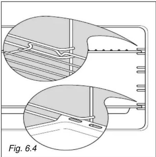
natural_image
Technical diagram showing two views of a mechanical component with internal structure and mounting holes (no text or symbols)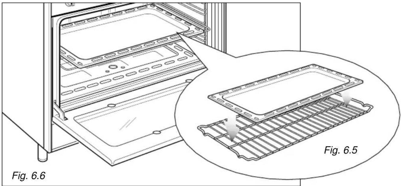
natural_image
Technical line drawing of an oven structure showing internal components and a magnified view of the grating (no text or symbols)REMOVING THE OVEN DOOR
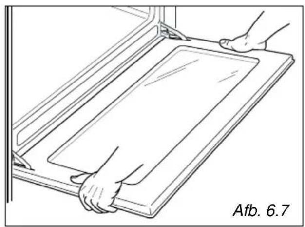
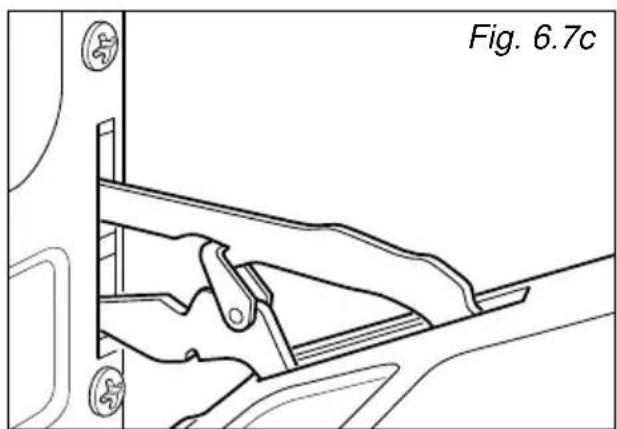
The oven door can easily be removed as follows:
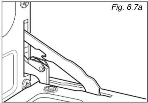
- Open the door to the full extent (fig. 6.7A).
- Attach the retaining rings to the hooks on the left and right hinges (fig. 6.7B).
- Hold the door as shown in fig. 6.7.
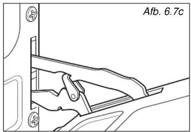
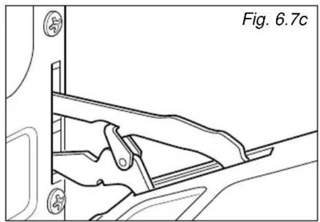
- Gently close the door and withdraw the lower hinge pins from their location (fig. 6.7C).
- Withdraw the upper hinge pins from their location (fig. 6.7D).
- Rest the door on a soft surface.
- To replace the door, repeat the above steps in reverse order.
natural_image
Technical line drawing of a mechanical bracket assembly (no text or symbols)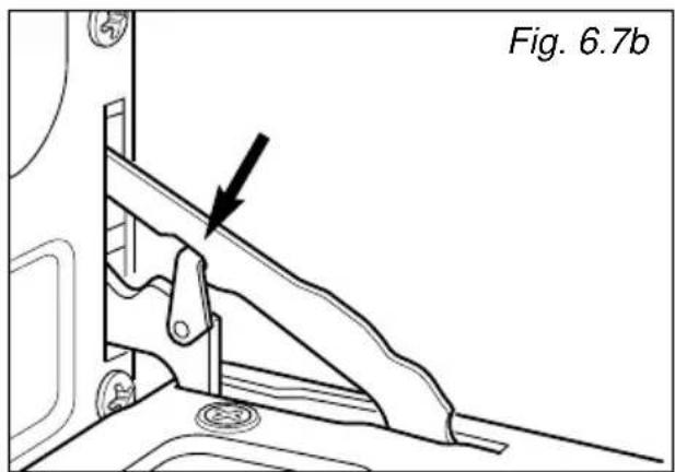
natural_image
Technical line drawing of a mechanical assembly with no visible text or symbols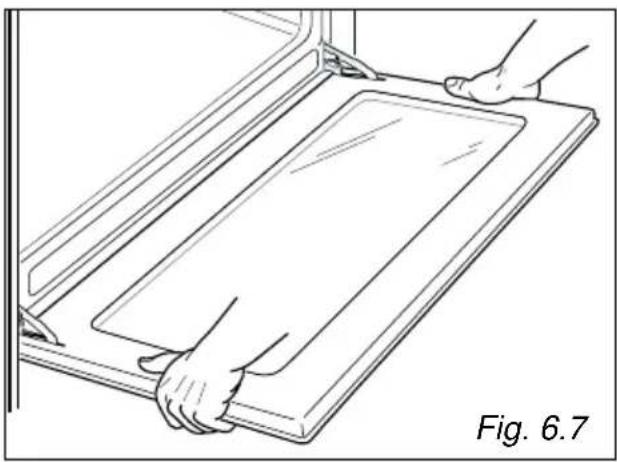
natural_image
Line drawing of hands installing or adjusting a rectangular panel on a door (no text or symbols)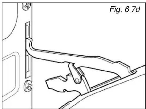
natural_image
Technical line drawing of a mechanical bracket or latch assembly (no text or symbols)Advice for the installer
IMPORTANT
- The appliance should be installed by a qualified technician in compliance with the laws in force in your country and in observation of the instructions supplied by the manufacturer.
- Always disconnect the cooker from mains power supply before carrying out any maintenance operations or repairs.
- Some appliances are supplied with a protective film on steel and aluminium parts. This film must be removed before using the appliance.
7 - INSTALLATION
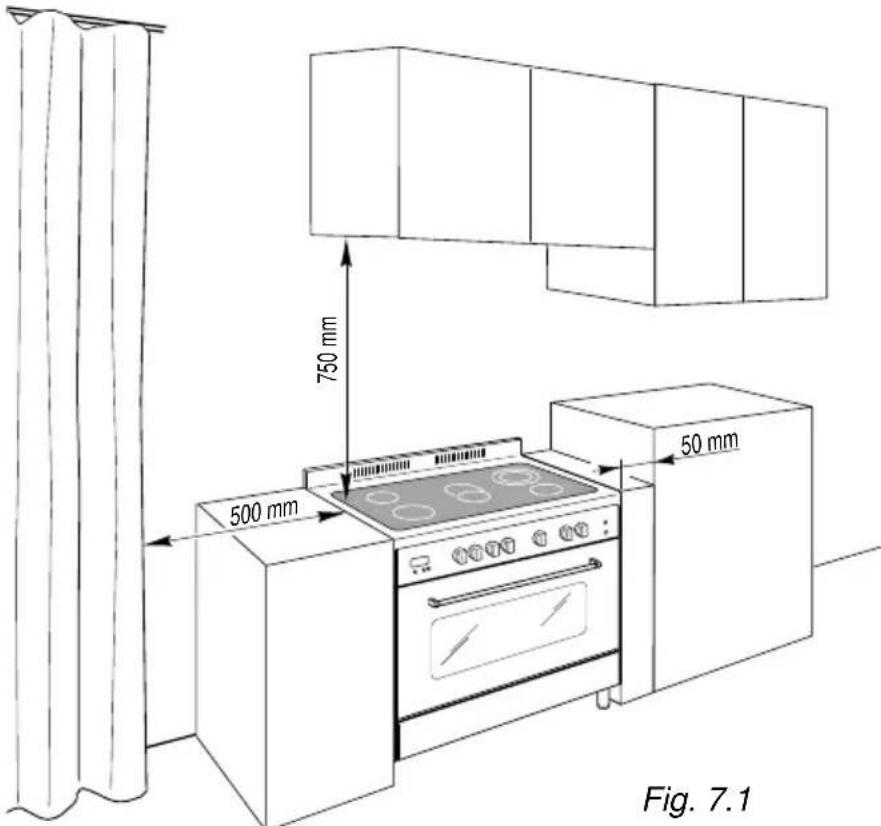
LOCATION
The appliance must be kept no less than 50 mm away from any side wall which exceed the height of the hob surface (fig. 7.1).
The appliance must be housed in heat resistant units.
The walls of the units must be capable of resisting temperatures of 75 °C above room temperature.
Do not install the appli- ance near inflammable materials (eg. curtains).
If the cooker is located on a pedestal it is necessary to provide safety measures to prevent falling out.
natural_image
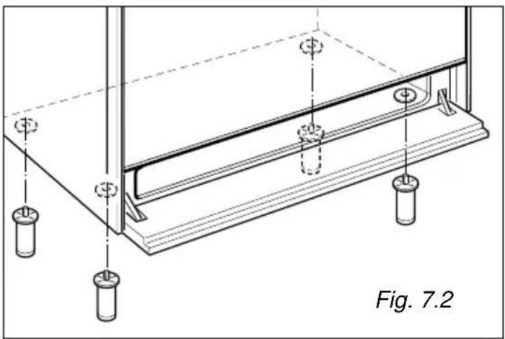
Technical line drawing of a structural assembly with mounting holes and supports (no text or symbols)FITTING THE ADJUSTABLE FEET
The adjustable feet must be fitted to the base of the cooker before use.
Rest the rear of the cooker an a piece of the polystyrene packaging exposing the base for the fitting of the feet.
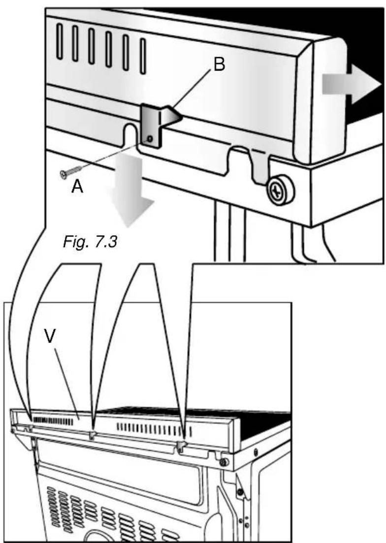
BACKGUARD
Before installing the cooker, assemble the backguard "V" (fig. 7.3).
Please note that :
- The backguard "V" can be found packed at the rear of the cooker.
- Before assembling remove any protective film/adhesive tape.
- The backguard must be fixed to the cooktop using the three supports "B" supplied with the appliance (see fig. 7.3).
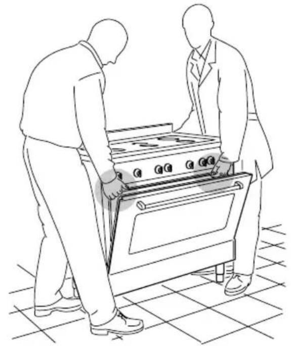
natural_image
Line drawing of two people installing or adjusting a large oven on a tiled floor (no text or symbols)Fig. 7.4
natural_image
Line drawing of a person using a stovetop on a tiled floor, with diagonal lines indicating crossed or unconnected components (no text or symbols)MOVING THE COOKER
WARNING
When raising cooker to upright position always ensure two people carry out this manoeuvre to prevent damage to the adjustable feet (fig. 7.4).
WARNING
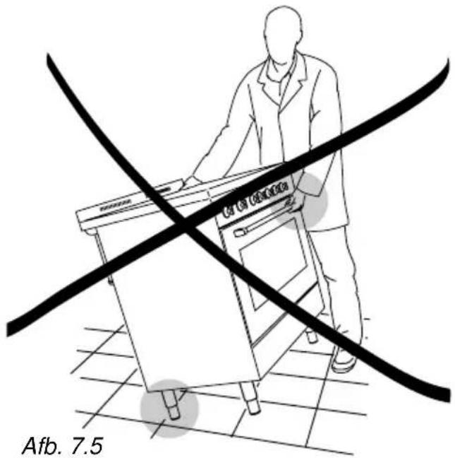
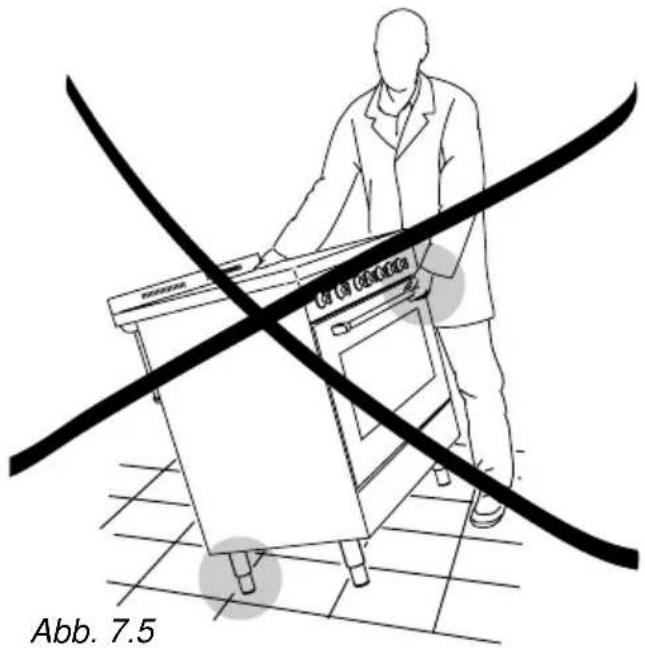
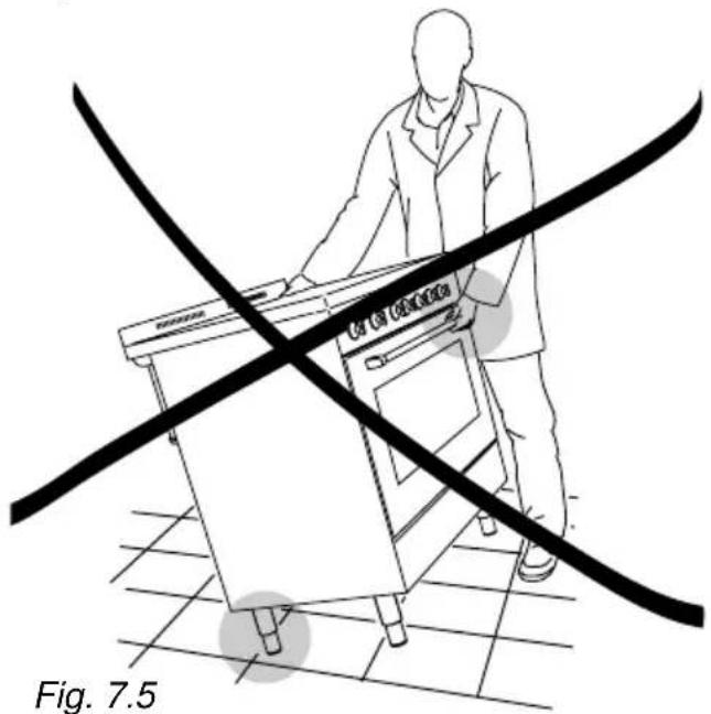
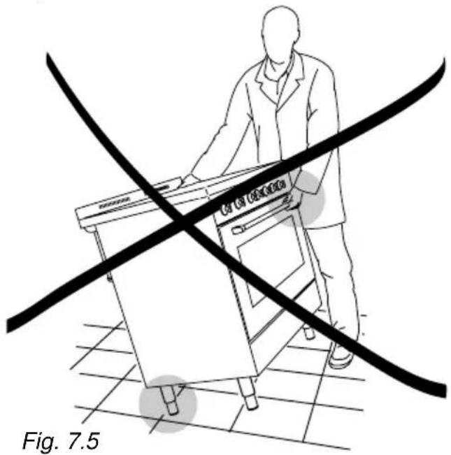
Be careful: DO NOT LIFT the cooker by the door handle when raising to the upright position (fig. 7.5).
WARNING
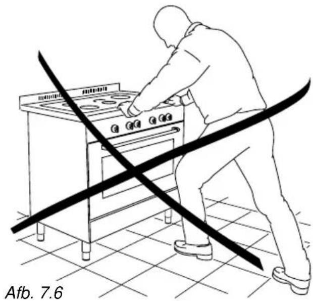
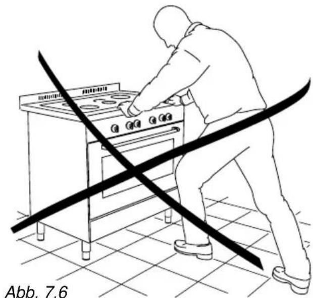
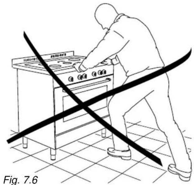
When moving cooker to its final position DO NOT DRAG (fig. 7.6).
Lift feet clear of floor (fig. 7.4).
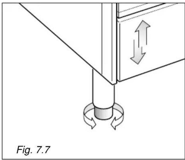
The cooker may be levelled by screwing the lower ends of the feet IN or OUT (fig. 7.7)
natural_image
Diagram of a mechanical assembly with directional arrows indicating motion, labeled Fig. 7.7 (no text or symbols on the diagram itself)IMPORTANT: The cooker must be installed in accordance with the manufacturer's instructions. Incorrect installation, for which the manufacturer accepts no responsibility, may cause injury to persons or animals etc.
GENERAL
- Connection to the mains must be carried out by qualified personnel in accordance with current regulations.
- The appliance must be connected to the mains checking that the voltage corresponds to the value given in the rating plate and that the electrical cable sections can withstand the load specified on the plate.
- The cooker can be connected directly to the mains placing an omnipolar switch with minimum opening between the contacts of 3 mm between the appliance and the mains.
- The power supply cable must not touch any hot parts and must be positioned so that it does not exceed 75°C at any point.
- Once the cooker has been installed, the switch or socket must always be accessible.
Before effecting any intervention on the electrical parts of the appliance, the connection to the network must be interrupted.
N.B. For connection to the mains, do not use adapters, reducers or branching devices as they can cause overheating and burning.
If the installation requires alterations to the domestic electrical system or if the socket and appliance plug are incompatible, call an expert.
He should also check that the socket cable section is suitable for the power absorbed by the appliance.
IMPORTANT: this cooker must be connected to a suitable double pole control unit adjacent to the cooker.
WARNING!
This appliance must be earthed.
The connection of the appliance to earth is mandatory.
The manufacturer declines all responsibility for any inconvenience resulting from the none observance of this condition.
CONNECTING THE FEEDER CABLE
To connect the feeder cable to the cooker it is necessary to:
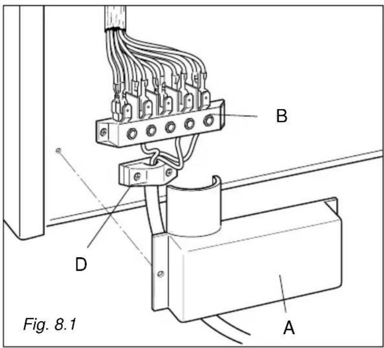
- Remove the two screws that hold shield A behind the cooker (Fig. 8.1).
- Open completely the cable clamp D.
- Fitted with a 5-pole terminal block, position the U bolts onto terminal block 'B' (fig. 8.1) according to the diagrams in figs. 8.2 - 8.3.
- Feed the supply cable through the cable clamp "D". The supply cable must be of a suitable size for the current requirements of the appliance; see the section "Feeder cable section"
- Connect the phase and earth cables to terminal B according figure 8.1.
- Pull the feeder cable and block it with the cable clamp D
- Re-mount shield A.
N.B. Earth cable must be 3 cm longer than neutral and live cables.
FEEDER CABLE SECTION "TYPE H05RR-F"
230V 3×6 mm 2 (**)
230V 4×4 mm 2 (**)
400V3N 5×2,5 mm 2 (**)
400V2N 4×4 mm 2 (**)
(**) – Connection with wall box connection.
- Contemporaneity factor applied
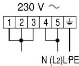
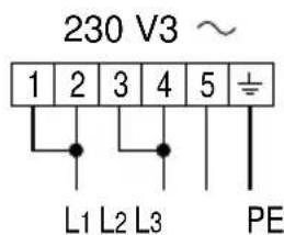
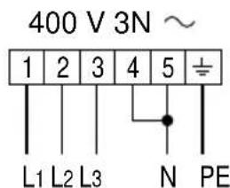
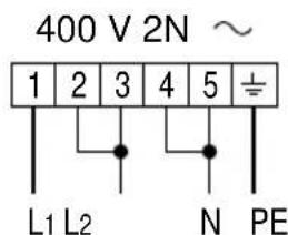
Fig. 8.2
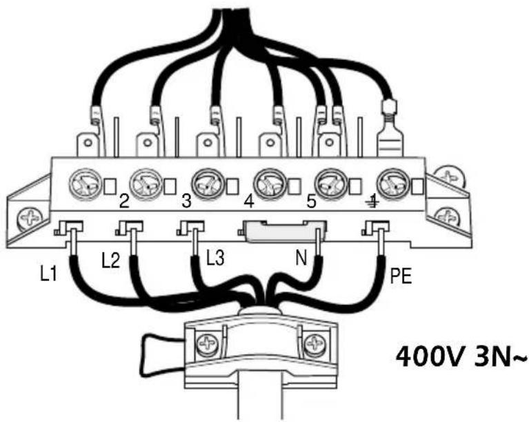
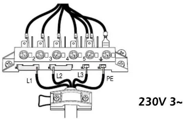
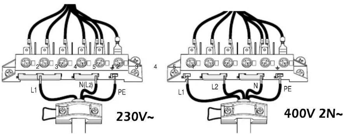
Fig. 8.3
The manufacturer cannot be held responsible for possible inaccuracies due to printing or transcription errors in the present booklet.
The manufacturer reserves the right to make all modifications to its products deemed necessary for manufacture or commercial reasons at any moment and without prior notice, without jeopardising the essential functional and safety characteristics of the appliances.
- BELANGRIJKE RAADGEVINGEN
- DOPPELE KOOKZONES
- CONTROLELAMPJE "PLAAT WARMI"
- - ELEKTRISCHE MULTIFUNKTIE OVEN
- Opgelet :
- TIMER
- KLOK (Afb. 5.2)
- OVENDEUR
- OVEN
- DEMONTAGE VAN DE OVENDEUR
- DE VERSTELBARE VOETEN MONTEREN
- BEWEGINGSSYSTEEM VAN HET FORNUIS
- WAARSCHUWING
- WICHTIGE HINWEISE
- DUO-SCHNELLKOCHZONE
- UHR (Abb. 5.2)
- OFENTÜR
- BACKOFEN
- Einbau-Anleitung
- WICHTIG
- KÜCHENHERD TRANSPORTIEREN
- HINWEIS
- Apreciado Cliente:
- ZONA RADIANTE DOUBLE Y OVAL
- - HORNO ELECTRICO MULTIFUNCION
- RELOJ (fig. 4.2)
- PUERTA DEL HORNO
- HORNO
- MONTAJE DE LAS PATAS AJUSTABLES
- CUIDADO:
- - PARTE ELECTRICA
- Dear Customer,
- IMPORTANT INFORMATION FOR CORRECT DISPOSAL OF THE PRODUCT IN ACCORDANCE WITH EC DIRECTIVE 2002/96/EC.
- USEFUL HINTS
- IMPORTANT INSTRUCTIONS AND ADVICE FOR THE USE OF ELECTRICAL APPLIANCES
- FIRST USE THE OVEN
- IMPORTANT PRECAUTIONS AND RECOMMENDATIONS
- IMPORTANT:
- VITROCERAMIC COOKING HOB
- - CONTROL PANEL
- CONTROL PANEL - Controls description
- Pilot lamps:
- - USE OF COOKING HOB
- IMPORTANT NOTE:
- CIRCUITS RADIANT ZONES
- DOUBLE AND OVAL RADIANT ZONES
- COOKING HINTS
- RESIDUAL HEAT INDICATOR
- During this period of time you should avoid touching the hob surface over the cooking area.
- Please pay special attention to ensuring children are not allowed near the hob.
- Cooking hints:
- ADVICE FOR SAFE USE OF THE COOKTOP
- CLEANING
- Before you begin cleaning make sure that the appliance is switched off.
- ATTENTION: MOST IMPORTANT!
- - MULTI-FUNCTION OVEN
- GENERAL FEATURES
- NOTE:
- WARNING:
- OPERATING PRINCIPLES
- a. by normal convection
- b. by forced convection
- c. by semi-forced convection
- d. by radiation
- e. by radiation and ventilation
- f. by ventilation
- THERMOSTAT KNOB (Fig. 4.2)
- FUNCTION SELECTOR KNOB (Fig. 4.1)
- OVEN LIGHT
- TRADITIONAL CONVECTION COOKING
- Recommended for:
- GRILLING
- DEFROSTING FROZEN FOODS
- HOT AIR COOKING
- VENTILATED GRILL COOKING
- THAWING AND WARMING UP
- CONVECTION COOKING WITH VENTILATION
- COOKING ADVICE STERILIZATION
- REGENERATION
- ROASTING
- SIMULTANEOUS COOKING OF DIFFERENT FOODS
- GRILLING AND "AU GRATIN"
- USE OF THE GRILL
- OVEN COOKING
- COOKING EXAMPLES
- DISHES TEMPERATURE
- - ELECTRONIC CLOCK/PROGRAMME
- Buttons description:
- CLOCK (fig. 5.2)
- MANUAL COOKING WITHOUT PRO- GRAMMER (fig. 5.3)
- TIMER (fig. 5.4)
- SEMI-AUTOMATIC COOKING (fig. 5.6)
- AUTOMATIC COOKING (fig. 5.7)
- - CLEANING AND MAINTENANCE
- Attention
- ENAMELLED PARTS
- STAINLESS STEEL SURFACES
- REPLACING THE OVEN LIGHT BULB
- OVEN DOOR
- STORAGE COMPARTMENT
- INSIDE OF OVEN
- ASSEMBLY AND DISMANTLING OF THE SIDE RUNNER FRAMES
- OVEN TRAY
- REMOVING THE OVEN DOOR
- Advice for the installer
- IMPORTANT
- - INSTALLATION
- LOCATION
- FITTING THE ADJUSTABLE FEET
- BACKGUARD
- MOVING THE COOKER
- WARNING
- GENERAL
- WARNING!
- CONNECTING THE FEEDER CABLE
- FEEDER CABLE SECTION "TYPE H05RR-F"
Brand : M-SYSTEM
Model : FK-95
Category : Cooker