
Studio 1557 - Laptop DELL - Free user manual and instructions
Find the device manual for free Studio 1557 DELL in PDF.


| Product Type | Notebook Laptop |
| Brand | Dell |
| Model | Studio 1557 / 1558 |
| Display Size | 15.6 inches (estimated) |
| Processor | Intel Core i3 / i5 / i7 (varies by configuration) |
| Memory | Up to 8 GB DDR3 (2 SODIMM slots) |
| Storage | 2.5-inch SATA hard drive (removable) |
| Optical Drive | Slot-load DVD±RW or Blu-ray (optional) |
| Wireless | WLAN (half Mini-Card), WWAN/UWB/Bluetooth (full Mini-Cards) |
| Ports | USB 2.0, HDMI, VGA, Ethernet, headphone/mic |
| Battery | Removable 6-cell or 9-cell lithium-ion |
| Power Adapter | 65W or 90W AC adapter |
| Camera | Integrated 1.3 MP webcam (optional) |
| Audio | Stereo speakers + subwoofer |
| Operating System | Windows 7 or Windows Vista (original) |
| Dimensions | Approx. 14.9 x 10.2 x 1.3 inches (378 x 260 x 33 mm) |
| Weight | Approx. 5.8 lbs (2.63 kg) with battery |
| Service Access | Removable base cover for memory, hard drive, Mini-Cards, fan |
| Repairability | User-serviceable components: RAM, hard drive, optical drive, wireless cards, keyboard, battery |
| Safety | ESD precautions, battery removal before servicing, use certified technician |
| BIOS Update | Flashable via Dell Support site (service tag required) |
Frequently Asked Questions - Studio 1557 DELL
User questions about Studio 1557 DELL
0 question about this device. Answer the ones you know or ask your own.
Ask a new question about this device
Download the instructions for your Laptop in PDF format for free! Find your manual Studio 1557 - DELL and take your electronic device back in hand. On this page are published all the documents necessary for the use of your device. Studio 1557 by DELL.
USER MANUAL Studio 1557 DELL
Back to Contents Page
Base Cover
Dell Studio™ 1557/1558 Service Manual
Removing the Base Cover
Replacing the Base Cover
WARNING: Before working inside your computer, read the safety information that shipped with your computer. For additional safety best practices information, see the Regulatory Compliance Homepage at www.dell.com/regulatory_compliance.
WARNING: Before performing these procedures, turn off the computer, disconnect the AC adapter from the electrical outlet and the computer, disconnect the modem from the wall connector and the computer, and remove any other external cables from the computer.
CAUTION: To avoid electrostatic discharge, ground yourself by using a wrist grounding strap or by periodically touching an unpainted metal surface (such as a connector on the back of the computer).
CAUTION: Only a certified service technician should perform repairs on your computer. Damage due to servicing that is not authorized by Dell™ is not covered by your warranty.
CAUTION: To help prevent damage to the system board, remove the main battery (see Before Working Inside Your Computer) before working inside the computer.
Removing the Base Cover
- Ensure that the computer is turned off.
- Remove the battery (see Before Working Inside Your Computer).
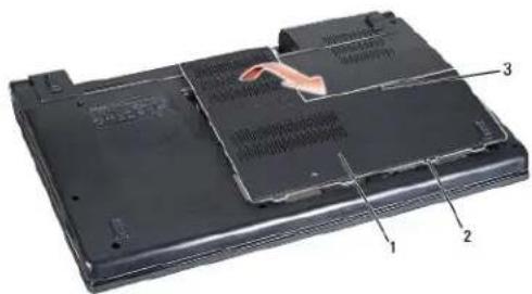
- Loosen the three captive screws on the base cover and lift the base cover off the computer at an angle as shown in the figure.
text_image
Labeled diagram of a laptop rear panel showing internal components and part numbers| 1 | base cover | 2 | tabs (4) |
| 3 | captive screws (3) |
Replacing the Base Cover
- Align the tabs on the base cover to the bottom of the computer.
- Tighten the three captive screws on the base cover.
- Slide the battery into the battery bay until it clicks into place.
Back to Contents Page
Back to Contents Page
Before You Begin
Dell Studio™ 1557/1558 Service Manual
Recommended Tools
Turning Off Your Computer
Before Working Inside Your Computer
This manual provides procedures for removing and installing the components in your computer. Unless otherwise noted, each procedure assumes that:
You have performed the steps in Before Working Inside Your Computer.
You have read the safety information that shipped with your computer.
When replacing a component, you have already removed the original component, if installed.
Recommended Tools
The procedures in this document may require the following tools:
Small flat-blade screwdriver
1 Phillips screwdriver
Small plastic scribe
Flash BIOS executable update program at support.dell.com
Turning Off Your Computer
CAUTION: To avoid losing data, save and close all open files and exit all open programs before you turn off your computer.
- Save and close all open files and exit all open programs.
- Shut down the operating system:
Windows Vista ^® :
Click the Start , click the arrow , and then click Shut Down.
Windows ^® 7:
Click the Start and then click Shut Down.
- Ensure that the computer is turned off. If your computer did not automatically turn off when you shut down the operating system, press and hold the power button until the computer turns off.
Before Working Inside Your Computer
Use the following safety guidelines to help protect your computer from potential damage and to help ensure your own personal safety.
WARNING: Before working inside your computer, read the safety information that shipped with your computer. For additional safety best practices information, see the Regulatory Compliance Homepage at www.dell.com/regulatory_compliance.
CAUTION: Only a certified service technician should perform repairs on your computer. Damage due to servicing that is not authorized by Dell is not covered by your warranty.
CAUTION: To avoid electrostatic discharge, ground yourself by using a wrist grounding strap or by periodically touching an unpainted metal surface, such as a connector on the back of the computer.
CAUTION: Handle components and cards with care. Do not touch the components or contacts on a card. Hold a card by its edges. Hold a component such as a processor by its edges, not by its pins.
CAUTION: When disconnecting a cable, pull on the cable's connector or on its pull-tab, not on the cable itself. For cable connectors with locking tabs, press inward on the locking tabs to release the connector. When connecting a cable, ensure that the connectors are correctly oriented and aligned to avoid damage to the connector and/or the connector's pins.
- Ensure that the work surface is flat and clean to prevent the computer cover from being scratched.
- Turn off your computer (see Turning Off Your Computer) and all attached devices.
CAUTION: To disconnect a network cable, first unplug the cable from your computer, and then unplug it from the network device.
- Disconnect all telephone or network cables from the computer.
- Disconnect your computer and all attached devices from their electrical outlets.
- Disconnect all attached devices from your computer.
- Press and eject any installed cards from the ExpressCard slot and the 8-In-1 Memory Card Reader.
CAUTION: To help prevent damage to the system board, you must remove the battery from the battery bay before you service the computer.
CAUTION: To avoid damage to the computer, use only the battery designed for this particular Dell computer. Do not use batteries designed for other Dell computers.
- Turn the computer over.
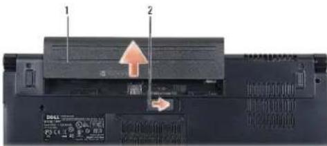
- Slide the battery release latch until it clicks into place.
- Slide the battery out of the battery bay.
text_image
Laptop screen rear panel with labeled components and indicator lights1 battery 2 battery release latch
- Turn the computer top side up, open the display, and press the power button to ground the system board.
Back to Contents Page
Flashing the BIOS
Dell Studio™ 1557/1558 Service Manual
- Turn on the computer.
- Go to the Dell Support website at support.dell.com.
- Click Drivers & Downloads® Select Model.
- Locate the BIOS update file for your computer:
NOTE: The Service Tag for your computer is located at the bottom of the computer.
If you have your computer's Service Tag:
a. Click Enter a Service Tag.
b. Enter your computer's Service Tag in the Enter a service tag: field, click Go, and proceed to step 5.
If you do not have your computer's Service Tag:
a. Select the type of product in the Select Your Product Family list.
b. Select the product brand in the Select Your Product Line list.
c. Select the product model number in the Select Your Product Model list.
NOTE: If you have selected a different model and want to start over again, click Start Over on the top right of the menu.
d. Click Confirm.
-
A list of results appear on the screen. Click BIOS.
-
Click Download Now to download the latest BIOS file. The File Download window appears.
-
Click Save to save the file on your desktop. The file downloads to your desktop.
-
Click Close if the Download Complete window appears. The file icon appears on your desktop and is titled the same as the downloaded BIOS update file.
-
Double-click the file icon on the desktop and follow the instructions on the screen.
Back to Contents Page
Internal Card With Bluetooth® Wireless Technology
Dell Studio™ 1557/1558 Service Manual
Removing the Bluetooth Card
Replacing the Bluetooth Card
WARNING: Before working inside your computer, read the safety information that shipped with your computer. For additional safety best practices information, see the Regulatory Compliance Homepage at www.dell.com/regulatory_compliance.
CAUTION: Only a certified service technician should perform repairs on your computer. Damage due to servicing that is not authorized by Dell™ is not covered by your warranty.
CAUTION: To avoid electrostatic discharge, ground yourself by using a wrist grounding strap or by periodically touching an unpainted metal surface (such as a connector on your computer).
CAUTION: To help prevent damage to the system board, remove the main battery (see Before Working Inside Your Computer) before working inside the computer.
If you ordered a card with Bluetooth wireless technology with your computer, it is already installed.
Removing the Bluetooth Card
- Follow the instructions in Before You Begin.
- Remove the palm rest (see Removing the Palm Rest).
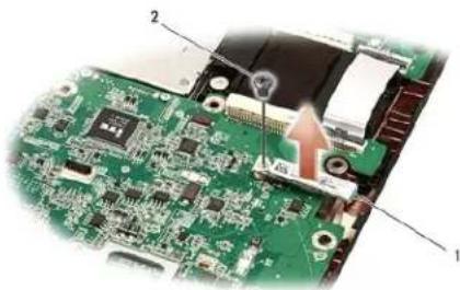
- Remove the screw that secures the Bluetooth card to the system board.
- Lift the Bluetooth card to disconnect it from the system board connector.
natural_image
Close-up of a green printed circuit board with labeled components (no readable text or symbols)| 1 | Bluetooth card | 2 | screw |
Replacing the Bluetooth Card
- Follow the instructions in Before You Begin.
- Align the connector on the Bluetooth card with the connector on the system board and press the Bluetooth card until it is fully seated.
- Replace the screw that secures the Bluetooth card to the system board.
- Replace the palm rest (see Replacing the Palm Rest).
Back to Contents Page
Back to Contents Page
Camera (Optional)
Dell Studio™ 1557/1558 Service Manual
Removing the Camera Module
Replacing the Camera Module
WARNING: Before working inside your computer, read the safety information that shipped with your computer. For additional safety best practices information, see the Regulatory Compliance Homepage at www.dell.com/regulatory_compliance.
CAUTION: To avoid electrostatic discharge, ground yourself by using a wrist grounding strap or by periodically touching an unpainted metal surface (such as a connector on the back of the computer).
CAUTION: Only a certified service technician should perform repairs on your computer. Damage due to servicing that is not authorized by Dell™ is not covered by your warranty.
CAUTION: To help prevent damage to the system board, remove the main battery (see Before Working Inside Your Computer) before working inside the computer.
Removing the Camera Module
- Follow the instructions in Before You Begin.
- Remove the display panel (see Removing the Display Panel).
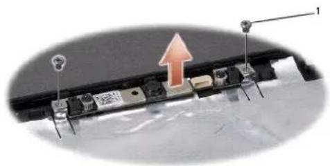
- Remove the two screws that secure the camera to the display cover.
- Lift the camera module from the display cover.
natural_image
Close-up of a laptop keyboard with an upward arrow and labeled components (no readable text or symbols)1 screws (2)
Replacing the Camera Module
- Follow the instructions in Before You Begin.
- Replace the two screws that secure the camera module to the display cover.
- Replace the display panel (see Replacing the Display Panel).
Back to Contents Page
Back to Contents Page
Center Control Cover
Dell Studio™ 1557/1558 Service Manual
Removing the Center Control Cover
Replacing the Center Control Cover
WARNING: Before working inside your computer, read the safety information that shipped with your computer. For additional safety best practices information, see the Regulatory Compliance Homepage at www.dell.com/regulatory_compliance.
CAUTION: To avoid electrostatic discharge, ground yourself by using a wrist grounding strap or by periodically touching an unpainted metal surface (such as a connector on the back of the computer).
CAUTION: Only a certified service technician should perform repairs on your computer. Damage due to servicing that is not authorized by Dell™ is not covered by your warranty.
CAUTION: To help prevent damage to the system board, remove the main battery (see Before Working Inside Your Computer) before working inside the computer.
Removing the Center Control Cover
- Follow the Instructions in Before You Begin.
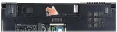
- In the battery bay, remove the screw that secures the center control cover.
natural_image
Close-up of a computer monitor rear panel showing internal components and a highlighted orange arrow pointing to a component (no visible text or symbols)- Turn the computer over and open the display as far as possible.
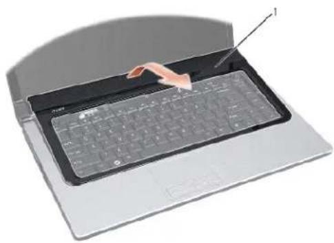
- Pry out the center control cover with a plastic scribe starting from the battery bay location at the back of the computer.
- Ease the center control cover up.
natural_image
Illustration of a hand holding a stylus interacting with a laptop keyboard (no text or symbols visible)1
center control cover
Replacing the Center Control Cover
- Follow the instructions in Before You Begin.
- Align the hooks beneath the center control cover with the slots on the palm rest and snap the cover in place.
- Close the display and turn over the computer.
- In the battery bay, replace the screw that secures the center control cover.
- Slide the battery into the battery bay until it clicks into place.
Back to Contents Page
Back to Contents Page
Coin-Cell Battery
Dell Studio™ 1557/1558 Service Manual
Removing the Coin-Cell Battery
Replacing the Coin-Cell Battery
WARNING: Before working inside your computer, read the safety information that shipped with your computer. For additional safety best practices information, see the Regulatory Compliance Homepage at www.dell.com/regulatory_compliance.
CAUTION: To avoid electrostatic discharge, ground yourself by using a wrist grounding strap or by periodically touching an unpainted metal surface (such as a connector on the back of the computer).
CAUTION: Only a certified service technician should perform repairs on your computer. Damage due to servicing that is not authorized by Dell™ is not covered by your warranty.
CAUTION: To help prevent damage to the system board, remove the main battery (see Before Working Inside Your Computer) before working inside the computer.
Removing the Coin-Cell Battery
- Follow the instructions in Before You Begin.
- Remove the base cover (see Removing the Base Cover).
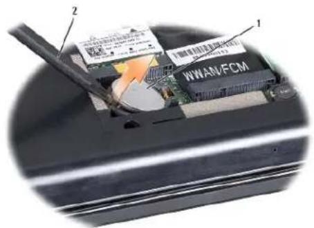
- Use a plastic scribe to pry up the coin-cell battery from the slot.
text_image
1 2 WWAN/FCM1 coin-cell battery 2 plastic scribe
Replacing the Coin-Cell Battery
- Follow the Instructions in Before You Begin.
- Hold the coin-cell battery with the positive side up.
- Slide the coin-cell battery into the slot and gently press until it snaps to the slot.
- Replace the base cover (see Replacing the Base Cover).
Back to Contents Page
Back to Contents Page
Processor Module
Dell Studio™ 1557/1558 Service Manual
Removing the Processor Module
Replacing the Processor Module
WARNING: Before working inside your computer, read the safety information that shipped with your computer. For additional safety best practices information, see the Regulatory Compliance Homepage at www.dell.com/regulatory_compliance.
CAUTION: To avoid electrostatic discharge, ground yourself by using a wrist grounding strap or by periodically touching an unpainted metal surface (such as a connector on the back of the computer).
CAUTION: To prevent intermittent contact between the ZIF-socket cam screw and the processor when removing or replacing the processor, press to apply slight pressure to the center of the processor while turning the cam screw.
CAUTION: To avoid damage to the processor, hold the screwdriver so that it is perpendicular to the processor when turning the cam screw.
CAUTION: Only a certified service technician should perform repairs on your computer. Damage due to servicing that is not authorized by Dell™ is not covered by your warranty.
CAUTION: To help prevent damage to the system board, remove the main battery (see Before Working Inside Your Computer) before working inside the computer.
Removing the Processor Module
- Follow the instructions in Before You Begin.
- Remove the processor heat sink (see Removing the Processor Heat Sink).
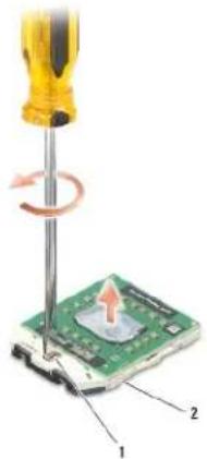
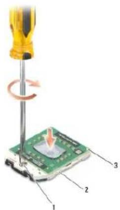
- To loosen the ZIF socket, use a small, flat-blade screwdriver and rotate the ZIF-socket cam screw counterclockwise until it comes to the cam stop.
text_image
Diagram showing a screwdriver using a computer to press a green circuit board, with labeled parts 1 and 2.1 ZIF-socket cam screw 2 ZIF socket
CAUTION: To ensure maximum cooling for the processor, do not touch the heat transfer areas on the processor thermal-cooling assembly. The oils in your skin can reduce the heat transfer capability of the thermal pads.
CAUTION: When removing the processor module, pull the module straight up. Be careful not to bend the pins on the processor module.
- Lift the processor module from the ZIF socket.
Replacing the Processor Module
NOTE: If a new processor is installed, you will receive a new thermal-cooling assembly, which will include an affixed thermal pad, or you will receive a new thermal pad along with documentation to illustrate proper installation.
- Follow the instructions in Before You Begin.
- Align the pin-1 corner of the processor module with the pin-1 corner of the ZIF socket, then insert the processor module.
NOTE: The pin-1 corner of the processor module has a triangle that aligns with the triangle on the pin-1 corner of the ZIF socket.
When the processor module is properly seated, all four corners are aligned at the same height. If one or more corners of the module are higher than the others, the module is not seated properly.
text_image
Diagram showing a screwdriver using a green circuit board to move a component, labeled with parts 1, 2, and 3.| 1 | ZIF-socket cam screw | 2 | ZIF socket |
| 3 | pin-1 corner |
CAUTION: To avoid damage to the processor, hold the screwdriver so that it is perpendicular to the processor when turning the cam screw.
- Tighten the ZIF socket by turning the cam screw clockwise to secure the processor module to the system board.
- Replace the processor heat sink (see Replacing the Processor Heat Sink).
Back to Contents Page
Back to Contents Page
Processor Heat Sink
Dell Studio™ 1557/1558 Service Manual
Removing the Processor Heat Sink
Replacing the Processor Heat Sink
WARNING: Before working inside your computer, read the safety information that shipped with your computer. For additional safety best practices information, see the Regulatory Compliance Homepage at www.dell.com/regulatory_compliance.
WARNING: If you remove the processor heat sink from the computer when the heat sink is hot, do not touch the metal housing of the processor heat sink.
CAUTION: To avoid electrostatic discharge, ground yourself by using a wrist grounding strap or by periodically touching an unpainted metal surface (such as a connector on the back of the computer).
CAUTION: Only a certified service technician should perform repairs on your computer. Damage due to servicing that is not authorized by Dell™ is not covered by your warranty.
CAUTION: To help prevent damage to the system board, remove the main battery (see Before Working Inside Your Computer) before working inside the computer.
Removing the Processor Heat Sink
- Follow the instructions in Before You Begin.
- Remove the optical drive (see Removing the Optical Drive).
- Disconnect the ExpressCard cables from their respective connectors on the system board (see Removing the ExpressCard Board).
- Disconnect the AC adapter connector cable, USB cable, fan cable, and the subwoofer cable from their respective connectors on the system board (see Removing the System Board Assembly).
- Remove the six screws that secure the system board to the computer base.
- Turn the system board over.
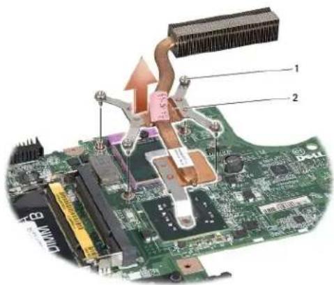
- In sequential order (indicated on the processor heat sink), loosen the four captive screws on the thermal-cooling assembly processor cover.
text_image
Diagram of a computer motherboard with labeled components and heat flow arrows indicating cooling or heating mechanism1 captive screws (4)
2 | processor heat sink
- Lift the processor heat sink off the computer.
Replacing the Processor Heat Sink
NOTE: The original thermal pad can be reused if the original processor and heat sink are reinstalled together. If either the processor or heat sink is replaced, use the thermal pad provided in the kit to ensure that thermal conductivity is achieved.
NOTE: This procedure assumes that you have already removed the processor heat sink and are ready to replace it.
- Follow the instructions in Before You Begin.
- Align the four captive screws on the thermal-cooling assembly processor cover with the screw holes on the system board and tighten the screws in sequential order.
- Replace the system board on the computer base.
- Replace the six screws that secure the system board to the computer base.
- Connect the AC adapter connector cable, USB cable, fan cable, and the subwoofer cable to their respective connectors on the system board (see Replacing the System Board Assembly).
- Connect the ExpressCard cables to their respective connectors on the system board (see Replacing the ExpressCard Board).
- Replace the optical drive (see Replacing the Optical Drive).
- Slide the battery into the battery bay until it clicks into place.
Back to Contents Page
Back to Contents Page
Display
Dell Studio™ 1557/1558 Service Manual
Display Assembly
Display Bezel
Display Panel
Display Hinges
Display Assembly
WARNING: Before working inside your computer, read the safety information that shipped with your computer. For additional safety best practices information, see the Regulatory Compliance Homepage at www.dell.com/regulatory_compliance.
CAUTION: To avoid electrostatic discharge, ground yourself by using a wrist grounding strap or by periodically touching an unpainted metal surface (such as a connector on the back of the computer).
CAUTION: Only a certified service technician should perform repairs on your computer. Damage due to servicing that is not authorized by Dell™ is not covered by your warranty.
CAUTION: To help prevent damage to the system board, remove the main battery (see Before Working Inside Your Computer) before working inside the computer.
Removing the Display Assembly
- Follow the instructions in Before You Begin.
- Remove the base cover (see Removing the Base Cover).
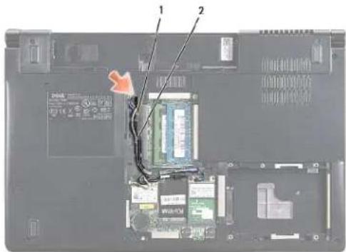
- Disconnect the antenna cables from the Mini-Card(s).
- Lift the antenna cables from the securing tabs and release them from the routing channel.
text_image
Laptop interior photo with visible circuit board and labeled components, showing internal wiring and a red arrow indicating a connection or repair point.| 1 | securing tabs | 2 | antenna cables |
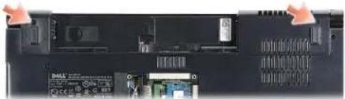
- Remove the two screws that secure the display assembly from the bottom of the computer.
natural_image
Close-up of a black electronic device with visible ports and buttons, no readable text or symbols present.- Remove the center control cover (see Removing the Center Control Cover).
-
Remove the keyboard (see Removing the Keyboard).
-
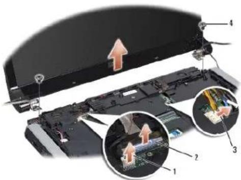
Disconnect the camera cable, display cable, and power button cable from the connectors on the system board and release it from the routing guides.
- Pull the antenna cables through the routing hole and release them from the routing channel.
- Remove the two screws that secure the display assembly to the computer base.
text_image
Labeled diagram of a computer monitor showing internal components and a magnified view of the circuit board with numbered parts.| 1 | camera cable connector | 2 | display cable connector |
| 3 | power button cable connector | 4 | screws (2) |
- Lift the display assembly off the computer base.
Replacing the Display Assembly
- Follow the instructions in Before You Begin.
- Align the display hinges with the holes in the computer base and then lower the display into place.
- Replace the two screws that secure the display assembly to the computer base.
- Slide the antenna cables through the routing hole to the base of the computer.
- Secure the camera cable, display cable, and power button cable to their routing guides.
- Connect the camera cable, display cable, and power button cable to their connectors on the system board.
NOTE: Ensure that the display and camera cables are properly routed and secured beneath the routing guides.
- Replace the keyboard (see Replacing the Keyboard).
- Replace the center control cover (see Replacing the Center Control Cover).
- Close the display and turn the computer over.
- Replace the two screws that secure the display assembly to the computer base.
- Replace the Mini-Card(s) and connect the antenna cables to it (see Replacing the Mini-Card).
- Replace the base cover (see Replacing the Base Cover).
Display Bezel
Removing the Display Bezel
WARNING: The following instructions are not applicable to Edge-to-Edge display panels, which should not be disassembled.
- Follow the instructions in Before You Begin.
- Remove the display assembly (see Removing the Display Assembly).
CAUTION: Removal of the bezel from the display bottom cover requires extreme care to avoid damage to the bezel and the display panel.
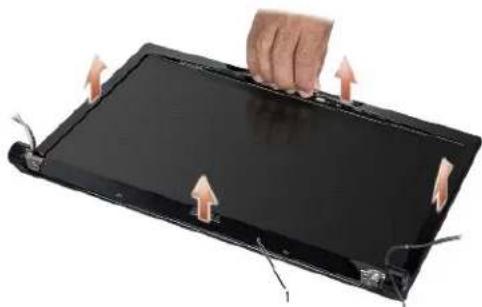
- Gently push the display bezel outwards on each of the four sides to release the bezel from the display panel.
natural_image
Hand pressing down on a black electronic device with arrows indicating motion (no text or symbols visible)1 display bezel
NOTE: In some computers, the display bezel has a double-sided tape on both ends. To avoid damage to the display bezel, remove the display bezel carefully to free it from the double-sided tape.
Replacing the Display Bezel
- Follow the instructions in Before You Begin.
- Starting at any corner, use your fingers to gently snap the bezel into place to secure it to the display panel.
- Replace the display assembly (see Replacing the Display Assembly).
Display Panel
Removing the Display Panel
- Follow the instructions in Before You Begin.
- Remove the display assembly (see Removing the Display Assembly).
- Remove the display bezel (see Removing the Display Bezel).
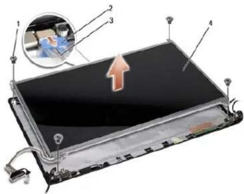
- Remove the four screws that secure the display panel to the display cover.
- Using the camera cable pull-tab, disconnect the camera cable from the connector on the camera.
text_image
Diagram of a device with numbered components and an inset showing a person inside a car's seat, highlighting a highlighted area.| 1 | screws (4) | 2 | camera cable pull-tab |
| 3 | camera cable | 4 | display panel |
- Lift the display panel out of the display cover.
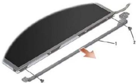
- Remove the four screws (two on each side of the display panel) that secure the display panel brackets to the display panel and remove the display panel brackets.
- Turn over the display panel.
natural_image
Diagram of a curved electronic component with labeled parts (1, 2, 3), showing internal structure and an orange arrow indicating direction (no text or symbols beyond labels)| 1 | display panel brackets (1 left, 1 right) | 2 | screws (4 total; 2 on each side) |
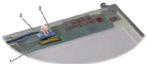
- Using the display cable pull-tab disconnect the display cable from the display board.
text_image
1 2 3 Digital Touch| 1 | display cable connector | 2 | display cable |
| 3 | display cable pull-tab |
Replacing the Display Panel
- Follow the instructions in Before You Begin.
-
Connect the display cable to the board at the back of the display panel.
-
Replace the four screws (two on each side of the display panel) to secure the display panel brackets to the display panel.
- Connect the camera cable to the connector on the camera.
- Align the screw holes on the display bracket with the screw holes and guide pins on the display cover and gently lower the display panel into place.
- Replace the four screws that secure the display panel to the display cover.
- Replace the display bezel (see Replacing the Display Bezel).
- Replace the display assembly (see Replacing the Display Assembly).
Display Hinges
Removing the Display Hinges
- Follow the instructions in Before You Begin.
- Remove the display assembly (see Removing the Display Assembly).
- Remove the display panel without removing the display bracket (see Removing the Display Panel).
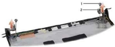
- Remove the two screws (one on each side) that secure the display hinges to the display cover.
- Remove the display hinges.
text_image
Diagram of a mechanical or electrical component with labeled parts 1 and 2, showing structural components and directional arrows.1 screws (2) 2 display hinges (2)
Replacing the Display Hinges
- Follow the instructions in Before You Begin.
- Align the holes on the display hinges with the holes on the display cover and replace the two screws (one on each side) that secure the display hinges to the display cover.
- Replace the display panel (see Replacing the Display Panel).
- Replace the display assembly (see Replacing the Display Assembly).
Back to Contents Page
Back to Contents Page
ExpressCard Board
Dell Studio™ 1557/1558 Service Manual
Removing the ExpressCard Board
Replacing the ExpressCard Board
WARNING: Before working inside your computer, read the safety information that shipped with your computer. For additional safety best practices information, see the Regulatory Compliance Homepage at www.dell.com/regulatory_compliance.
CAUTION: To avoid electrostatic discharge, ground yourself by using a wrist grounding strap or by periodically touching an unpainted metal surface (such as a connector on the back of the computer).
CAUTION: Only a certified service technician should perform repairs on your computer. Damage due to servicing that is not authorized by Dell™ is not covered by your warranty.
CAUTION: To help prevent damage to the system board, remove the main battery (see Before Working Inside Your Computer) before working inside the computer.
Removing the ExpressCard Board
- Follow the instructions in Before You Begin.
- Remove the palm rest (see Removing the Palm Rest).
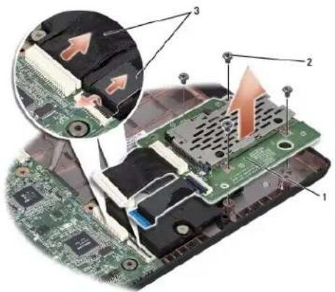
- Disconnect the ExpressCard cables from the connectors on the system board.
- Remove the four screws that secure the ExpressCard board to the computer base and remove the board.
text_image
Diagram of a computer motherboard with labeled components and an inset showing a close-up of internal circuit boards.| 1 | ExpressCard board | 2 | screws (4) |
| 3 | ExpressCard cables (2) |
Replacing the ExpressCard Board
- Follow the instructions in Before You Begin.
- Connect the ExpressCard board cables to the system board connectors.
- Place the ExpressCard board in position and replace the four screws to secure the ExpressCard board.
CAUTION: Before turning on the computer, replace all screws and ensure that no stray screws remain inside the computer. Failure to do so may result in damage to the computer.
- Replace the palm rest (see Replacing the Palm Rest).
Back to Contents Page
Back to Contents Page
Fan
Dell Studio™ 1557/1558 Service Manual
Removing the Fan
Replacing the Fan
WARNING: Before working inside your computer, read the safety information that shipped with your computer. For additional safety best practices information, see the Regulatory Compliance Homepage at www.dell.com/regulatory_compliance.
CAUTION: To avoid electrostatic discharge, ground yourself by using a wrist grounding strap or by periodically touching an unpainted metal surface (such as a connector on the back of the computer).
CAUTION: Only a certified service technician should perform repairs on your computer. Damage due to servicing that is not authorized by Dell™ is not covered by your warranty.
CAUTION: To help prevent damage to the system board, remove the main battery (see Before Working Inside Your Computer) before working inside the computer.
Removing the Fan
- Follow the instructions in Before You Begin.
- Remove the optical drive (see Removing the Optical Drive).
- Remove the six screws that secure the system board to the computer base.
- Lift the system board off the computer base.
- Remove the two screws that secure the fan to the computer base.
-
Lift the fan off the computer base.
-
Disconnect the AC adapter connector cable, USB cable, fan cable, and the subwoofer cable from their respective connectors on the system board.

natural_image
Close-up of a mechanical device showing a fan with internal components and a highlighted orange arrow indicating motion (no text or symbols visible)1 screws (2) 2 fan cable
Replacing the Fan
- Follow the instructions in Before You Begin.
- Place the fan on the computer base and replace the two screws that secure the fan to the computer base.
- Place the system board on computer base.
-
Replace the six screws that secure the system board to the computer base.
-
Connect the AC adapter connector cable, USB cable, fan cable, and the subwoofer cable to their respective connectors on the system board.
-
Replace the optical drive (see Replacing the Optical Drive).
Back to Contents Page
Back to Contents Page
Hard Drive
Dell Studio™ 1557/1558 Service Manual
Removing the Hard Drive
Replacing the Hard Drive
WARNING: If you remove the hard drive from the computer when the drive is hot, do not touch the metal housing of the hard drive.
WARNING: Before working inside your computer, read the safety information that shipped with your computer. For additional safety best practices information, see the Regulatory Compliance Homepage at www.dell.com/regulatory_compliance.
CAUTION: To prevent data loss, turn off your computer (see Before Working Inside Your Computer) before removing the hard drive. Do not remove the hard drive while the computer is on or in the Sleep state.
CAUTION: Hard drives are extremely fragile. Exercise care when handling the hard drive.
CAUTION: Only a certified service technician should perform repairs on your computer. Damage due to servicing that is not authorized by Dell™ is not covered by your warranty.
CAUTION: To help prevent damage to the system board, remove the main battery (see Before Working Inside Your Computer) before working inside the computer.
NOTE: Dell does not guarantee compatibility or provide support for hard drives obtained from sources other than Dell.
NOTE: If you are installing a hard drive from a source other than Dell, you need to install an operating system, drivers, and utilities on the new hard drive (see the Dell Technology Guide).
Removing the Hard Drive
- Follow the instructions in Before You Begin.
- Remove the base cover (see Removing the Base Cover).
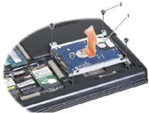
- Remove the four screws that secure the hard drive assembly to the computer base.
- Slide the hard drive assembly to the side to disconnect it from the hard drive connector and lift it out of the computer base.
text_image
Laptop internal components diagram with numbered labels pointing to a drive or memory card interface1 hard drive assembly 2 screws (4)
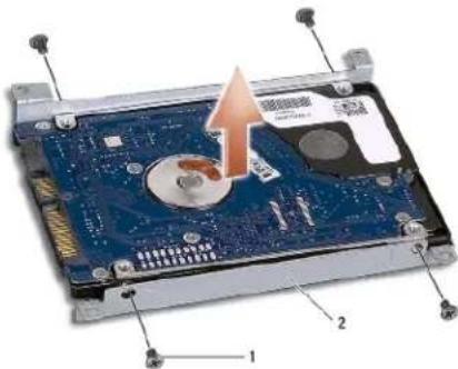
- Remove the four screws that secure the hard drive bracket to the hard drive.
- Lift the hard drive off the hard drive bracket.
text_image
Diagram of a hard disk drive showing internal components and labeled parts, with an orange arrow indicating motion or assembly.1 screws (4) 2 hard drive bracket
CAUTION: When the hard drive is not in the computer, store it in protective antistatic packaging. For more information, see "Protecting Against Electrostatic Discharge" in the safety information that shipped with your computer.
Replacing the Hard Drive
- Follow the instructions in Before You Begin.
- Align the screw holes on the hard drive bracket with the screw holes on the hard drive and replace the four screws that secure the hard drive bracket to the hard drive.
- Place the hard drive assembly in the computer base.
- Slide in the hard drive assembly to connect it to the hard drive connector on the system board.
- Replace the four screws that secure the hard drive assembly to the computer base.
- Replace the base cover (see Replacing the Base Cover).
CAUTION: Before turning on the computer, replace all screws and ensure that no stray screws remain inside the computer. Failure to do so may result in damage to the computer.
CAUTION: Do not follow the operating system installation process if the hard drive is a Factory-Imaged Hard Drive (FIHD). The operating system is already installed in the FIHD.
- Install the operating system and drivers and utilities for your computer, as needed (see the Dell Technology Guide).
Back to Contents Page
Back to Contents Page
Keyboard
Dell Studio™ 1557/1558 Service Manual
Removing the Keyboard
Replacing the Keyboard
WARNING: Before working inside your computer, read the safety information that shipped with your computer. For additional safety best practices information, see the Regulatory Compliance Homepage at www.dell.com/regulatory_compliance.
CAUTION: To avoid electrostatic discharge, ground yourself by using a wrist grounding strap or by periodically touching an unpainted metal surface (such as a connector on the back of the computer).
CAUTION: Only a certified service technician should perform repairs on your computer. Damage due to servicing that is not authorized by Dell™ is not covered by your warranty.
CAUTION: To help prevent damage to the system board, remove the main battery (see Before Working Inside Your Computer) before working inside the computer.
Removing the Keyboard
- Follow the instructions in Before You Begin.
- Remove the center control cover (see Removing the Center Control Cover).
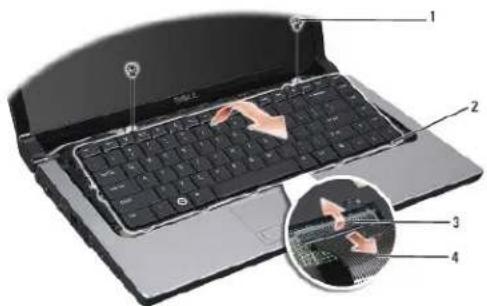
- Remove the two screws at the top of the keyboard.
CAUTION: The key caps on the keyboard are fragile, easily dislodged, and time-consuming to replace. Be careful when removing and handling the keyboard.
-
Lift the keyboard and hold it to access the keyboard cable connector.
-
Disconnect the keyboard cable from the keyboard cable connector on the system board by rotating the keyboard cable connector latch towards the front of the computer.
-
Slide the keyboard cable out of the keyboard cable connector.
NOTE: If you have the backlit keyboard (optional), you must remove the keyboard backlight cable from the connector on the system board.
text_image
Laptop keyboard diagram with numbered parts and magnified detail view showing key components| 1 | screws (2) | 2 | keyboard tabs |
| 3 | keyboard cable connector | 4 | keyboard cable |
Replacing the Keyboard
-
Follow the instructions in Before You Begin.
-
Slide the keyboard cable into the keyboard cable connector on the system board.
- Rotate the keyboard cable connector latch to secure the keyboard cable.
- Align the tabs along the bottom of the keyboard and slide them into the slots of the palm rest.
- Press on the corner edges near the top to snap the keyboard into place.
- Replace the two screws at the top of the keyboard.
- Replace the center control cover (see Replacing the Center Control Cover).
Back to Contents Page
Back to Contents Page
Battery Latch Assembly
Dell Studio™ 1557/1558 Service Manual
Removing the Battery Latch Assembly
Replacing the Battery Latch Assembly
WARNING: Before working inside your computer, read the safety information that shipped with your computer. For additional safety best practices information, see the Regulatory Compliance Homepage at www.dell.com/regulatory_compliance.
CAUTION: To avoid electrostatic discharge, ground yourself by using a wrist grounding strap or by periodically touching an unpainted metal surface (such as a connector on the back of the computer).
CAUTION: Only a certified service technician should perform repairs on your computer. Damage due to servicing that is not authorized by Dell™ is not covered by your warranty.
CAUTION: To help prevent damage to the system board, remove the main battery (see Before Working Inside Your Computer) before working inside the computer.
Removing the Battery Latch Assembly
- Follow the instructions in Before You Begin.
- Remove the base cover (see Removing the Base Cover).
- Remove all memory modules (see Removing the Memory Module(s)).
- Remove the hard drive (see Removing the Hard Drive).
- Remove the Mini-Card(s) (see Removing the Mini-Card).
- Remove the center control cover (see Removing the Center Control Cover).
- Remove the keyboard (see Removing the Keyboard).
- Remove the palm rest (see Removing the Palm Rest).
- Remove the optical drive (see Removing the Optical Drive).
- Remove the system board (see Removing the System Board Assembly).
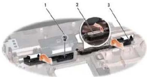
- Remove the latch spring from the hook that holds it in place.
CAUTION: Before you remove the battery release latch, observe the orientation of the latch to ensure proper installation when the latch is replaced.
- Remove the screw that secures the battery latch to the battery release latch and take the latch out from the computer base.
text_image
Technical diagram of a mechanical assembly with numbered components and an inset close-up view showing internal components.| 1 | screw | 2 | latch spring |
| 3 | battery latch assembly |
Replacing the Battery Latch Assembly

CAUTION: Ensure the battery latch assembly is properly oriented. The indent for the screw should face up when installing the assembly.
- Follow the instructions in Before You Begin.
- Slide the battery latch assembly into place.
- Replace the screw that secures the battery latch to the battery release latch.
- Using a small screwdriver, place the spring over the hook on the computer base.
- Follow the steps in Removing the Battery Latch Assembly in the reverse order.
Back to Contents Page
Back to Contents Page
Memory
Dell Studio™ 1557/1558 Service Manual
Removing the Memory Module(s)
Replacing the Memory Module(s)
WARNING: Before working inside your computer, read the safety information that shipped with your computer. For additional safety best practices information, see the Regulatory Compliance Homepage at www.dell.com/regulatory_compliance.
CAUTION: To avoid electrostatic discharge, ground yourself by using a wrist grounding strap or by periodically touching an unpainted metal surface (such as a connector on the back of the computer).
CAUTION: Only a certified service technician should perform repairs on your computer. Damage due to servicing that is not authorized by Dell™ is not covered by your warranty.
CAUTION: To help prevent damage to the system board, remove the main battery (see Before Working Inside Your Computer) before working inside the computer.
You can increase your computer memory by installing memory modules on the system board. See "Specifications" in your Setup Guide for information on the memory supported by your computer. Install only memory modules that are intended for your computer.
NOTE: Memory modules purchased from Dell™ are covered under your computer warranty.
Your computer has two user-accessible SODIMM sockets, DIMM A and DIMM B, accessed from the bottom of the computer.
CAUTION: If you need to install memory modules in two connectors, install a memory module in the connector labeled "DIMM A" before you install a module in the connector labeled "DIMM B."
Removing the Memory Module(s)
- Follow the instructions in Before You Begin.
- Remove the base cover (see Removing the Base Cover).
CAUTION: To prevent damage to the memory module connector, do not use tools to spread the memory module securing clips.
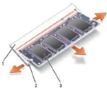
- Use your fingertips to carefully spread apart the securing clips on each end of the memory module connector until the module pops up.
- Remove the memory module from the memory module connector.
text_image
Diagram of a memory chip with labeled components and directional arrows indicating flow or movement| 1 | memory module connector | 2 | securing clips (2) |
| 3 | memory module |
Replacing the Memory Module(s)
- Follow the instructions in Before You Begin.
-
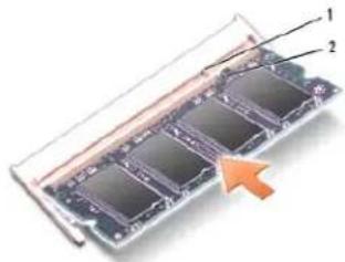
Align the notch in the module edge connector with the tab in the connector slot.
-
Slide the memory module firmly into the slot at a 45-degree angle, and press the memory module down until it clicks into place. If you do not hear the click, remove the memory module and reinstall it.

NOTE: If the memory module is not installed properly, the computer may not boot.
text_image
Diagram of a memory card with labeled components and an arrow indicating direction| 1 | tab | 2 | notch |

CAUTION: If the base cover is difficult to close, remove the module and reinstall it. Forcing the base cover to close may damage your computer.
- Replace the base cover (see Replacing the Base Cover).
- Slide the battery into the battery bay until it clicks into place, or connect the AC adapter to your computer and an electrical outlet.
- Turn on the computer.
As the computer boots, it detects the additional memory and automatically updates the system configuration information.
To verify that the memory is installed correctly:
Windows Vista ^® :
Click the Start → Control Panel→ System and Maintenance.
Windows 7:
Click the Start → Control Panel → System and Security → System.
Back to Contents Page
Back to Contents Page
Communication Cards
Dell Studio™ 1557/1558 Service Manual
Subscriber Identity Module
Wireless Mini-Cards
WARNING: Before working inside your computer, read the safety information that shipped with your computer. For additional safety best practices information, see the Regulatory Compliance Homepage at www.dell.com/regulatory_compliance.
CAUTION: To avoid electrostatic discharge, ground yourself by using a wrist grounding strap or by periodically touching an unpainted metal surface (such as a connector on the back of the computer).
CAUTION: Only a certified service technician should perform repairs on your computer. Damage due to servicing that is not authorized by Dell™ is not covered by your warranty.
CAUTION: To help prevent damage to the system board, remove the main battery (see Before Working Inside Your Computer) before working inside the computer.
Subscriber Identity Module
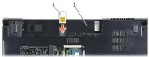
Subscriber Identity Modules (SIM) identify users uniquely through an International Mobile Subscriber Identity.
Installing the SIM
- Follow the Instructions in Before You Begin.
- In the battery bay, slide the SIM into the compartment.
text_image
Labeled diagram of a computer rear panel showing internal components and a battery pack with text labels| 1 | SIM | 2 | battery bay |
Removing the SIM
Press the SIM into the slot to release it. When it is partially ejected, remove the SIM from the battery bay.
Wireless Mini-Cards
NOTE: Dell does not guarantee compatibility or provide support for Mini-Cards from sources other than Dell.
Your computer supports three Mini-Card slots:
Two full Mini-Card slots — for WWAN, WPAN, UWB, and Bluetooth®
1 One half Mini-Card slot — for WLAN
NOTE: Depending on the configuration of your system, one or more of the Mini-Cards might not be present.
The types of Mini-Cards supported are:
Wireless Local Area Network (WLAN) — Half Mini-Card
Ultra Wide Band (UWB) — Full Mini-Card
Mobile broadband or Wireless Wide Area Network (WWAN) — Full Mini-Card
1 Wireless Personal Area Network (WPAN) or Internal Card with Bluetooth Wireless Technology — Full Mini-Card
NOTE: Your computer can only support two full Mini-Cards and one half Mini-Card at a time.
NOTE: The WLAN slot supports a half Mini-Card.
Removing the Mini-Card
- Follow the instructions in Before You Begin.
- Remove the base cover (see Removing the Base Cover).
CAUTION: When you disconnect a cable, pull on its connector or on its pull-tab, not on the cable itself. Some cables have connectors with locking tabs; if you are disconnecting this type of cable, press in on the locking tabs before you disconnect the cable. As you pull connectors apart, keep them evenly aligned to avoid bending any connector pins. Also, before you connect a cable, ensure that both connectors are correctly oriented and aligned.
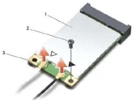
- Disconnect the antenna cables from the Mini-Card.
text_image
Diagram of a device with labeled components and directional arrows indicating movement or assembly1 WWAN/WLAN Mini-Card 2 securing screw 3 antenna cable connectors (2)
NOTE: If you are removing a WPAN/UWB Mini-Card, disconnect the blue antenna cable from the Mini-Card.
- Remove the screw that secures the Mini-Card to the system board.
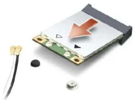
- Lift the Mini-Card out of the system board connector.
natural_image
Close-up of a damaged electronic circuit board with a red downward arrow and surrounding components (no text or symbols visible)CAUTION: When the Mini-Card is not in the computer, store it in protective antistatic packaging. For more information, see "Protecting Against Electrostatic Discharge" in the safety information that shipped with your computer.
Replacing the Mini-Card
CAUTION: Install the UWB Mini-Card in the WWAN or WPAN slot. Do not install a UWB Mini-Card in the WLAN card slot. Doing so may cause damage to your computer.
- Follow the instructions in Before You Begin.
- Remove the new Mini-Card from its packaging.
CAUTION: Use firm and even pressure to slide the card into place. If you use excessive force, you may damage the connector.
- Insert the Mini-Card connector at a 45-degree angle into the appropriate system board connector. For example, the WLAN card connector is labeled WLAN and so on.
- Press the other end of the Mini-Card down into the slot.
- Replace the screw that secures the Mini-Card to the system board.
- Connect the appropriate antenna cables to the Mini-Card you are installing. The following table provides the antenna cable color scheme for each Mini-Card supported by your computer.
| Connectors on the Mini-Card | Antenna Cable Color Scheme |
| WWAN (2 antenna cables) | |
| Main WWAN (white triangle) | white with gray stripe |
| Auxiliary WWAN (black triangle) | black with gray stripe |
| WLAN (2 or 3 antenna cables) | |
| Main WLAN (white triangle) | white |
| Auxiliary WLAN (black triangle) | black |
| MIMO WLAN (^gray triangle) | gray |
| * The MIMO WLAN is optional and may not be available in all computers. | |
NOTE: The gray antenna cable may not be available in all computers. The availability of the gray antenna cable in the Mini-Card compartment depends on the type of display.
- Secure the unused antenna cables in the protective mylar sleeve.
- Replace the base cover (see Replacing the Base Cover).
- Slide the battery into the battery bay until it clicks into place.
- Install the drivers and utilities for your computer, as required. For more information, see the Dell Technology Guide.
Back to Contents Page
Optical Drive
Dell Studio™ 1557/1558 Service Manual
Removing the Optical Drive
Replacing the Optical Drive
WARNING: Before working inside your computer, read the safety information that shipped with your computer. For additional safety best practices information, see the Regulatory Compliance Homepage at www.dell.com/regulatory_compliance.
CAUTION: To avoid electrostatic discharge, ground yourself by using a wrist grounding strap or by periodically touching an unpainted metal surface (such as a connector on the back of the computer).
CAUTION: Only a certified service technician should perform repairs on your computer. Damage due to servicing that is not authorized by Dell™ is not covered by your warranty.
CAUTION: To help prevent damage to the system board, remove the main battery (see Before Working Inside Your Computer) before working inside the computer.
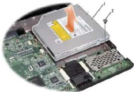
Removing the Optical Drive
- Follow the instructions in Before You Begin.
- Remove the palm rest (see Removing the Palm Rest).
- Remove the screw on the optical drive.
- Slide the optical drive to the side and lift the optical drive from the computer base.
natural_image
Close-up of a computer motherboard with an open drive and a highlighted internal component (no text or symbols visible)| 1 | optical drive | 2 | screw |
Replacing the Optical Drive
- Follow the instructions in Before You Begin.
- Place the optical drive in the computer base.
- Slide in the optical drive to connect it to the optical drive connector on the system board.
- Replace the screw that secures the optical drive to the computer base.
- Replace the palm rest (see Replacing the Palm Rest).
Back to Contents Page
Back to Contents Page
Palm Rest
Dell Studio™ 1557/1558 Service Manual
Removing the Palm Rest
Replacing the Palm Best
WARNING: Before working inside your computer, read the safety information that shipped with your computer. For additional safety best practices information, see the Regulatory Compliance Homepage at www.dell.com/regulatory_compliance.
CAUTION: To avoid electrostatic discharge, ground yourself by using a wrist grounding strap or by periodically touching an unpainted metal surface (such as a connector on the back of the computer).
CAUTION: Only a certified service technician should perform repairs on your computer. Damage due to servicing that is not authorized by Dell™ is not covered by your warranty.
CAUTION: To help prevent damage to the system board, remove the main battery (see Before Working Inside Your Computer) before working inside the computer.
Removing the Palm Rest
- Follow the instructions in Before You Begin.
- Remove the base cover (see Removing the Base Cover).
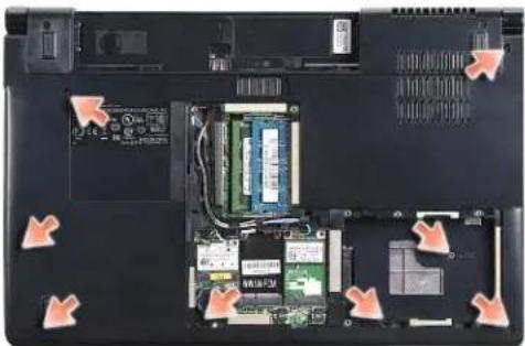
- Remove the eight screws from the bottom of the computer.
natural_image
Laptop interior showing internal circuit board and memory components with orange arrows indicating movement or orientation (no text or symbols visible)- Remove the Mini-Card(s) (see Removing the Mini-Card).
- Remove the antenna cables from their cable routing.
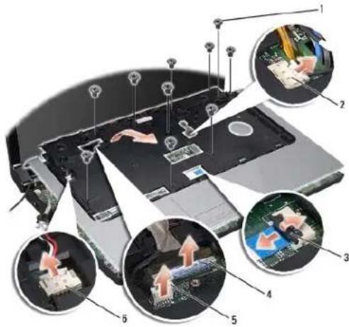
- Disconnect the display cable, camera cable, and the power button cable from their respective system board connectors (see Removing the Display Assembly).
- Disconnect the touch pad cable and speaker cable from their respective system board connectors.
- Remove the ten screws on the palm rest.
CAUTION: Do not use force to separate the palm rest from the computer. If you encounter resistance, gently flex or apply pressure to the palm rest, or move along the edge, working away from the area of resistance, until the palm rest is free.
text_image
Laptop interior diagram with numbered annotations showing component placement and circuitry setup| 1 | screws (10) | 2 | power button connector |
| 3 | touch pad connector | 4 | display cable connector |
| 5 | camera cable connector | 6 | speaker connector |
- Carefully lift the palm rest along the rear edge, near the hinge brackets, then gently lift the palm rest to remove it from the computer.
Replacing the Palm Rest
-
Follow the instructions in Before You Begin.
-
Align the palm rest with the base of the computer and gently snap it into place.
-
Replace the ten screws on the palm rest.
-
Connect the touch pad cable and speaker cable to the respective system board connectors.
-
Connect the display cable, camera cable, and power button cable to the respective system board connectors (see Replacing the Display Assembly).
-
Slide the antenna cables through their cable routing (see Replacing the Display Assembly).
-
Replace the Mini-Card(s) (see Replacing the Mini-Card).
-
Replace the eight screws at the bottom of the computer.
-
Replace the base cover (see Replacing the Base Cover).
Back to Contents Page
Back to Contents Page
Power Button Board
Dell Studio™ 1557/1558 Service Manual
Removing the Power Button Board
Replacing the Power Button Board
WARNING: Before working inside your computer, read the safety information that shipped with your computer. For additional safety best practices information, see the Regulatory Compliance Homepage at www.dell.com/regulatory_compliance.
CAUTION: To avoid electrostatic discharge, ground yourself by using a wrist grounding strap or by periodically touching an unpainted metal surface (such as a connector on the back of the computer).
CAUTION: Only a certified service technician should perform repairs on your computer. Damage due to servicing that is not authorized by Dell™ is not covered by your warranty.
CAUTION: To help prevent damage to the system board, remove the main battery (see Before Working Inside Your Computer) before working inside the computer.
Removing the Power Button Board
- Follow the instructions in Before You Begin.
- Remove the display hinges (see Removing the Display Hinges).
text_image
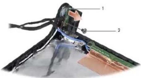
Labeled diagram of a device showing internal components with numbered parts1 power button board 2 screw
- Remove the screw that secures the power button board to the display cover.
- Lift the power button board off the display cover.
Replacing the Power Button Board
- Follow the Instructions in Before You Begin.
- Align the screw hole on the power button board with the screw hole on the display cover and replace the screw.
- Replace the display hinges (see Replacing the Display Hinges).
- Slide the battery into the battery bay, until it clicks in place.
Back to Contents Page
Back to Contents Page
AC Adapter Connector
Dell Studio™ 1557/1558 Service Manual
Removing the AC Adapter Connector
Replacing the AC Adapter Connector
WARNING: Before working inside your computer, read the safety information that shipped with your computer. For additional safety best practices information, see the Regulatory Compliance Homepage at www.dell.com/regulatory_compliance.
CAUTION: To avoid electrostatic discharge, ground yourself by using a wrist grounding strap or by periodically touching an unpainted metal surface (such as a connector on the back of the computer).
CAUTION: Only a certified service technician should perform repairs on your computer. Damage due to servicing that is not authorized by Dell™ is not covered by your warranty.
CAUTION: To help prevent damage to the system board, remove the main battery (see Before Working Inside Your Computer) before working inside the computer.
Removing the AC Adapter Connector
- Follow the instructions in Before You Begin.
- Remove the optical drive (see Removing the Optical Drive).
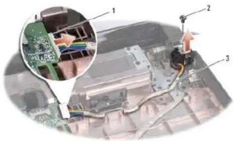
- Remove the screw that secures the AC adapter connector.
- Remove the AC adapter cable from the routing guide.
- Disconnect the AC adapter cable from the system board connector.
- Lift the AC adapter connector and cable out of the computer base.
text_image
Technical diagram showing a circuit board with labeled components and an inset close-up of a microchip or connector assembly.| 1 | AC adapter cable connector | 2 | screw |
| 3 | cable routing |
Replacing the AC Adapter Connector
- Follow the instructions in Before You Begin.
- Place the AC adapter connector in the computer base.
- Replace the screw that secures the AC adapter connector.
- Route the AC adapter cable through the routing guide.
- Connect the AC adapter cable to the system board connector.
CAUTION: Before turning on the computer, replace all screws and ensure that no stray screws remain inside the computer. Failure to do so may result in damage to the computer.
- Replace the optical drive (see Replacing the Optical Drive).
Back to Contents Page
Back to Contents Page
Speaker Assembly
Dell Studio™ 1557/1558 Service Manual
Removing the Speaker Assembly
Replacing the Speaker Assembly
WARNING: Before working inside your computer, read the safety information that shipped with your computer. For additional safety best practices information, see the Regulatory Compliance Homepage at www.dell.com/regulatory_compliance.
CAUTION: To avoid electrostatic discharge, ground yourself by using a wrist grounding strap or by periodically touching an unpainted metal surface (such as a connector on the back of the computer).
CAUTION: Only a certified service technician should perform repairs on your computer. Damage due to servicing that is not authorized by Dell™ is not covered by your warranty.
CAUTION: To help prevent damage to the system board, remove the main battery (see Before Working Inside Your Computer) before working inside the computer.
Removing the Speaker Assembly
- Follow the instructions in Before You Begin.
- Remove the palm rest (see Removing the Palm Rest).
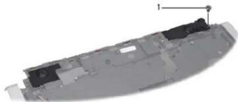
- Remove the screw on the palm rest.
natural_image
3D rendered mechanical component with a numbered annotation (1) pointing to a specific part, no visible text or symbols.1 screw
- Turn the palm rest over.
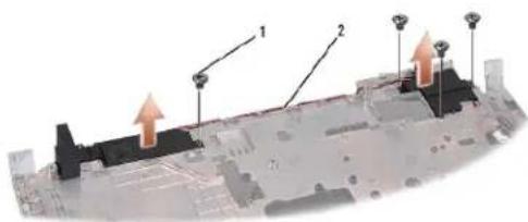
- Remove the four screws on the speakers.
- Release the speaker cable from the securing tabs on the palm rest and take out the speaker assembly.
text_image
Technical diagram of a ship's deck with labeled components and directional arrows indicating movement or force1 screws (4) 2 speaker cable
Replacing the Speaker Assembly
-
Follow the instructions in Before You Begin.
-
Replace the four screws that secure the speaker assembly to the palm rest.
- Route the speaker cables carefully through the securing tabs on the palm rest.
- Turn the palm rest over.
- Replace the screw on the palm rest.
- Replace the palm rest (see Replacing the Palm Rest).
Back to Contents Page
Back to Contents Page
Subwoofer Assembly
Dell Studio™ 1557/1558 Service Manual
Removing the Subwoofer Assembly
Replacing the Subwoofer Assembly
WARNING: Before working inside your computer, read the safety information that shipped with your computer. For additional safety best practices information, see the Regulatory Compliance Homepage at www.dell.com/regulatory_compliance.
CAUTION: To avoid electrostatic discharge, ground yourself by using a wrist grounding strap or by periodically touching an unpainted metal surface (such as a connector on the back of the computer).
CAUTION: Only a certified service technician should perform repairs on your computer. Damage due to servicing that is not authorized by Dell™ is not covered by your warranty.
CAUTION: To help prevent damage to the system board, remove the main battery (see Before Working Inside Your Computer) before working inside the computer.
Removing the Subwoofer Assembly
- Follow the instructions in Before You Begin.
- Remove the optical drive (see Removing the Optical Drive).
- Disconnect the AC adapter connector cable, USB cable, fan cable, and the subwoofer cable from their respective connectors on the system board.
- Remove the six screws that secure the system board to the computer base.
- Lift the system board off the computer base.
- Release the subwoofer assembly cable from the routing guides.
- Remove the three screws on the subwoofer assembly.
- Lift the subwoofer assembly from the computer base.
1 screws (3) 2 subwoofer
Replacing the Subwoofer Assembly
- Follow the instructions in Before You Begin.
- Place the subwoofer assembly on the computer base and replace the three screws that secure the subwoofer assembly to the computer base.
- Route the subwoofer assembly cable along the routing guides.
-
Replace the system board on the computer base.
-
Replace the six screws that secure the system board to the computer base.
- Connect the AC adapter connector cable, USB cable, fan cable, and the subwoofer cable to their respective connectors on the system board.
- Replace the optical drive (see Replacing the Optical Drive).
Back to Contents Page
©
©
Back to Contents Page
Dell Studio™ 1557/1558 Service Manual

NOTE: A NOTE indicates important information that helps you make better use of your computer.

CAUTION: A CAUTION indicates potential damage to hardware or loss of data if instructions are not followed.
A WARNING indicates a potential for property damage, personal injury, or death.
Information in this document is subject to change without notice. © 2009 Dell Inc. All rights reserved.
Reproduction of these materials in any manner whatsoever without the written permission of Dell Inc. is strictly forbidden.
Trademarks used in this text: Dell and the DELL logo are trademarks of Dell Inc.; Bluetooth is a registered trademark owned by Bluetooth SIG, Inc. and is used by Dell under license; Microsoft, Windows, Windows Vista, and Windows Vista start button logo are either trademarks or registered trademarks of Microsoft Corporation in the United States and/or other countries.
Other trademarks and trade names may be used in this document to refer to either the entities claiming the marks and names or their products. Dell Inc. disclaims any proprietary interest in trademarks and trade names other than its own.
September 2009 Rev. A00
Back to Contents Page
Back to Contents Page
USB Connector
Dell Studio™ 1557/1558 Service Manual
Removing the USB Connector
Replacing the USB Connector
WARNING: Before working inside your computer, read the safety information that shipped with your computer. For additional safety best practices information, see the Regulatory Compliance Homepage at www.dell.com/regulatory_compliance.
CAUTION: To avoid electrostatic discharge, ground yourself by using a wrist grounding strap or by periodically touching an unpainted metal surface (such as a connector on the back of the computer).
CAUTION: Only a certified service technician should perform repairs on your computer. Damage due to servicing that is not authorized by Dell™ is not covered by your warranty.
CAUTION: To help prevent damage to the system board, remove the main battery (see Before Working Inside Your Computer) before working inside the computer.
Removing the USB Connector
- Follow the Instructions in Before You Begin.
- Remove the optical drive (see Removing the Optical Drive).
- Remove the AC adapter connector (see Removing the AC Adapter Connector).
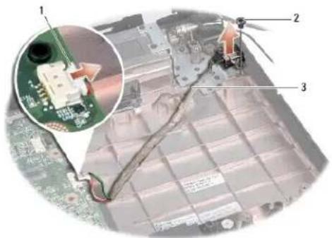
- Remove the screw that secures the USB connector.
- Remove the USB connector cable from the routing guide.
- Disconnect the USB connector cable from the system board connector.
- Lift the USB connector and cable out of the computer base.
text_image
Technical diagram showing a battery pack with labeled components and an inset close-up of the circuit board assembly.| 1 | USB connector cable | 2 | screw |
| 3 | USB connector cable routing |
Replacing the USB Connector
- Follow the instructions in Before You Begin.
- Place the USB connector and cable in the computer base.
- Replace the screw that secures the USB connector.
-
Route the USB connector cable through the routing guide.
-
Connect the USB connector cable to the system board connector.

CAUTION: Before turning on the computer, replace all screws and ensure that no stray screws remain inside the computer. Failure to do so may result in damage to the computer.
-
Replace the AC adapter connector (see Replacing the AC Adapter Connector).
-
Replace the optical drive (see Replacing the Optical Drive).
Back to Contents Page