USA 203 P - Car stereo Soundstream - Free user manual and instructions
Find the device manual for free USA 203 P Soundstream in PDF.


User questions about USA 203 P Soundstream
0 question about this device. Answer the ones you know or ask your own.
Ask a new question about this device
Download the instructions for your Car stereo in PDF format for free! Find your manual USA 203 P - Soundstream and take your electronic device back in hand. On this page are published all the documents necessary for the use of your device. USA 203 P by Soundstream.
USER MANUAL USA 203 P Soundstream
text_image
USA SERIESP203
&
P205
Multi-Channel Power Amplifiers
OWNERS MANUAL AND
INSTALLATION GUIDE
SOUNDSTREAM®
T E C H N 0 L 0 G I E S
CONGRA TULA TIONS / HERZL ICHEN GLÜCKWUNSCH!!
You now awn a Soundstream Amplifier, handcrafted in the USA, it is the result of a unique design and engineering philosophy.
To maximize the performance of your system, we recommend that you thoroughly acquaint yourself with its capabilities and features. Please retain this manual and your sales and installation receipts for future reference.
Soundstream amplifiers are manufactured with the highest quality control standards. When properly installed, they will provide you with many years of listening pleasure. Please record the following information which will help protect your investment should your amplifier ever need replacement or service
Prolonged listening at high /eve/s may result in hearing loss. Even though your new Soundstream amplifier sounds better than anything you've ever beard, exercise caution to prevent hearing damage.
ACHTUNG!
- +12V Connected to fuse or circuit breaker, then battery's positive post.
- Ground Main ground connection. Bolt to a clean chassis ground in the vehicle.
- Remote - Remote turn-on input from the head unit. Accepts +12V.
- Speaker Output Connections-Channels 1 &2.
- Speaker Output Connections Sub Channels.
- Crossover Adjustment Pot - Crossover frequency setting for the subwoofer low pass filter.
- Input Level Variable from 40mV to 2.5V—Subwoofer Channel.
- Crossover Switch Select "IN" to use the amplifier's internal high pass filter, or "OUT" to bypass the internal crossover.
- Crossover Adjustment Pot-Crossover frequency setting for the channels 1 & 2 high pass filter.
10 Input Level -Variable from 100mV to 2.5V—Channels 1&2.
11 Inputs - Right and left channel inputs for channels 1 & 2 and the subwoofer. - LED Indicates amplifier power on.
P205 - 5 Channel Amplifier
text_image
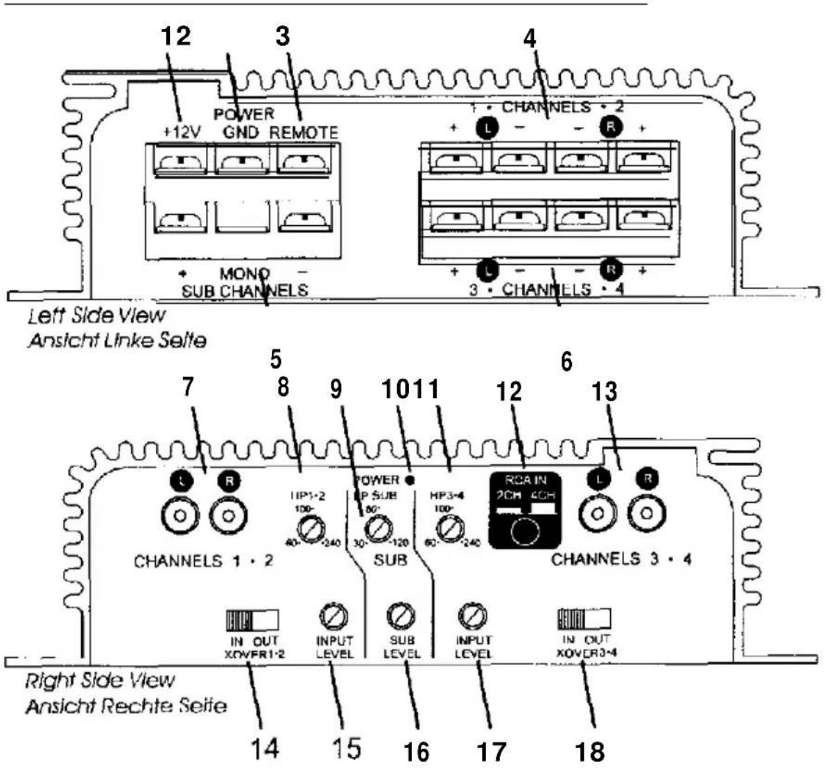
12 3 4 POWER +12V GND REMOTE + MONO - SUB CHANNELS CHANNELS 2 L - - R + + L - - R + 3 · CHANNELS 4 Left Side View Ansicht Linke Seite 7 5 8 9 10 11 12 6 13 CHANNELS 1 · 2 R IIP1-2 100- 40 - - 240 POWER P SUB 60' 30 - - 120 SUB HP3-4 100- 60 - - 240 RCA IN 2CH 4CH CHANNELS 3 · 4 L R IN OUT XOVER1-2 INPUT LEVEL SUB LEVEL INPUT LEVEL IN OUT XOVER3-4 Right Side View Ansicht Rechte Seite 14 15 16 17 18Kev to Callouts
- +12V - Connected to fuse or circuit breaker, then battery's positive post.
- Ground Main ground connection. Bolt to a clean chassis ground in the vehicle.
- Remote Remote turn-on input from the head unit. Accepts +12V.
- Speaker Output Connections Channels 1 & 2.
- Speaker Output Connections Sub Channels.
- Speaker Output Connections Channels 3 & 4.
- Inputs Right and left channel inputs for channels 1 & 2.
- Crossover Adjustment Pot - Crossover frequency setting for the channels 1 & 2 high pass filter.Subwoofer Crossover Switch Select "IN" to use the amplifier's internal low pass filter, or "OUT" to use an external crossover.
- Crossover Adjustment Pot Crossover frequency setting for the subwoofer low pass filter.
- LED Indicates amplifier power on.
- Crossover Adjustment Pot - Crossover frequency setting for the channels 3 & 4 high pass filter. Inputs Right and left channel inputs for channels 1 & 2 and the subwoofer.
- Channels 3 & 4 Input Select - Switches to allow all channels to be driven from 2 (CH 1 & 2) or 4 RCA inputs
- Inputs Right and left channel inputs for channels 3 8 4.
- Channels 1 & 2 Crossover Switch - Select "IN" to use the amplifier's internal high pass filter. or "OUT" to bypass the internal crossover.
- Input Level -Variable from 100mV to 2.5V—Channels 1 & 2.
- Input Level - Variable from 40mV to 2.5V—Subwoofer Channel.
17, Input Level -Variable from 100mV to 2.5V—Channels 3 & 4.
18 Channels 3 & 4 Crossover Switch - Select "IN" to use the amplifier's internal high pass filter, or "OUT" bypass the internal crossover.
WIRING
POWER AND GROUND
To assure maximum output from your amplifier, use high quality, low-loss power and ground cables. Soundstream amplifiers incorporate gold-plated barrier strips for maximum power transfer and protection from corrosion. The screw terminals back out for use with spade & ring terminals. Determine from the chart below the minimum gauge power and ground wire for your application.
| Model | up to 10' | up to 20' |
| P203 | 10 or 12 ga. | 10 ga. |
| P205 | 10 or 12 ga. | 10 ga. |
CIRCUIT BREAKERS/FUSES
EXTERNAL
Like all audio components, the Soundstream amplifiers must be fused near the battery A fuse or circuit breaker must be located within 18" of the battery This will prevent a fire in the event of a shorted cable. See the chart below to determine the value of your battery Fuse/circuit breaker.
INTERNAL
The Soundstream amplifiers are fused internally with automotive-type fuses. The fuse is accessible on the left side of the amplifier. Never replace the fuses with a higher value than what is supplied. This may result in amplifier damage and will void the warranty!
(Continued on page 9)
| Model | Amplifier Fuses | Battery Fuse/Circuit Breaker |
| P203 | (1) 30 amp automotive | 40 amp |
| P205 | (2) 20 amp automotive | 50 amp |
(Continued from page 8)
REMOTE TURN-ON
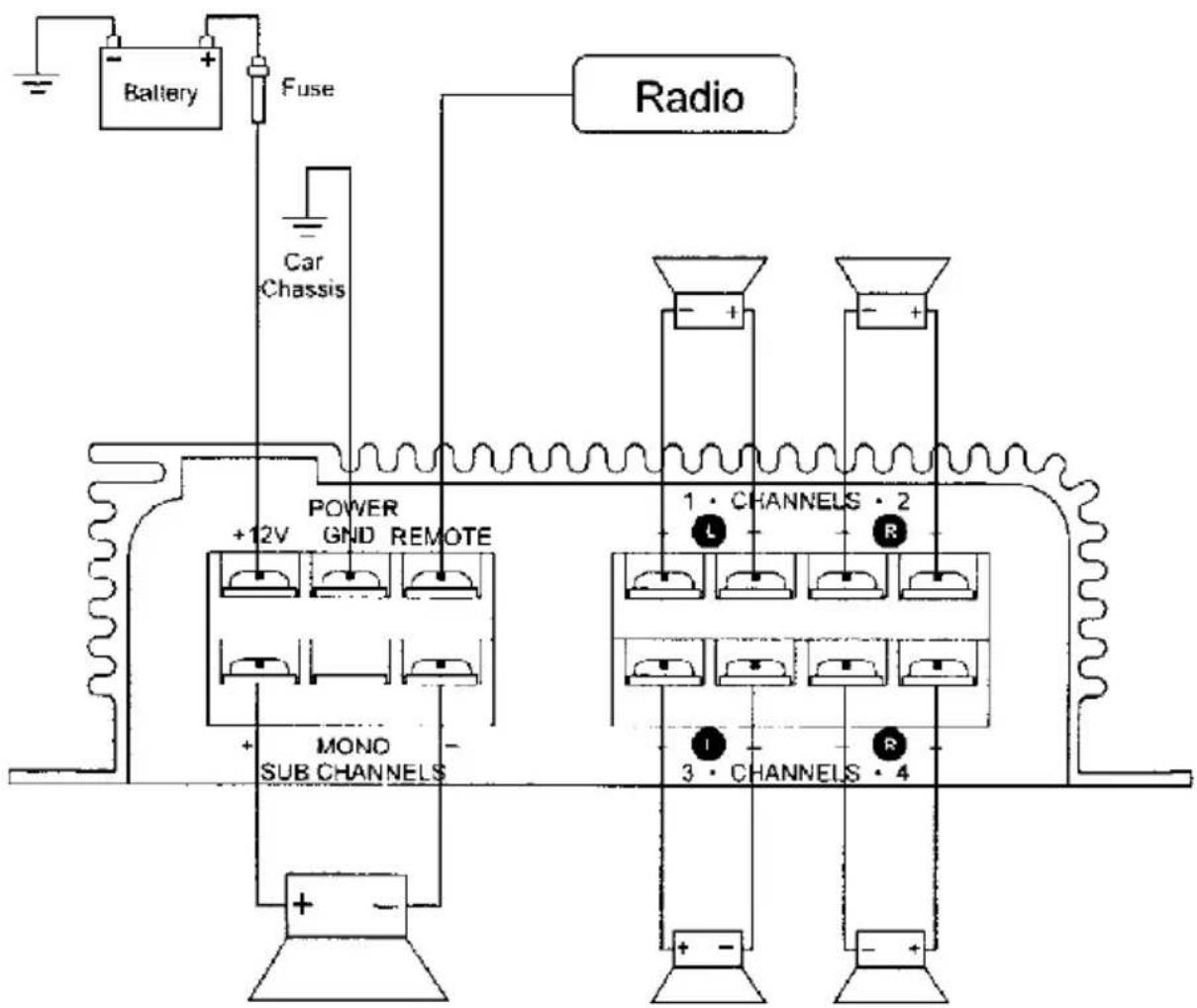
Connect the "Remote" to the turn-on lead from the source unit. When +12 volts is received, the amplifier will turn on.
SIGNAL CABLE
To guarantee optimum performance, use a high-quality cable that will be easy to install and has minimal signal loss.
SPEAKER CABLE
Use a high quality, flexible, multi-strand cable for best performance and longevity.
WIRING DIAGRAM
flowchart
graph TD
    Battery["Battery"] --> Fuse["Fuse"]
    Fuse --> Power["POWER +12V GND REMOTE"]
    Power --> SubChannels["MONO SUB CHANNELS"]
    SubChannels --> Power
    Power --> Radio["Radio"]
    Power --> Channel1["1 • CHANNELS • 2"]
    Power --> Channel2["3 • CHANNELS • 4"]
    Channel1 --> Channel3["• L"]
    Channel2 --> Channel4["• R"]
    Channel3 --> Power
    Channel4 --> Power
    Power --> CarChassis["Car Chassis"]
    Power --> MotorCap["+ -"]
PROTECTION CIRCUITRY
Your Soundstream amplifier is protected against both overheating and short circuits by means of the following circuits:
- Main power supply fuses.
- Speaker output protection.
• A fail-safe thermal protection circuit activating at WC.
NOTE: If you experience blown main power supply fuses, DO NOT increase values beyond the original values! Doing so will void your warranty and may damage your amplifier.
TROUBLESHOOTING
| PROBLEM | CAUSE |
| No sound and LED is not lit | . no power or ground at amp. no remote turn-on signal• blown fuse “ear battery. blown amp power supply fuse |
| Repeatedly blown amp fuse, frequent activation of Thermal Protection Circuit | • check speaker configuration—impedance may be less than 2 ohms stereo or 4 ohms mono. speaker or leads may be shorted• verify adequate amplifier ventilation |
SERVICE
Your Soundstream amplifier is protected by a limited warranty. Please read the enclosed warranty card.
SPECIFICATIONS
POWER OUTPUT
| MODEL | Power4 ohms | Power2 ohms |
| P203 | 35w x 2 +70w x 1 | 50w x 2 +100w x 1 |
| P205 | 35w x 4 +70w x 1 | 50w x 4 +100w x 1 |
THD < 0.1%
Signal to Noise > 90 dB
Frequency Response 20 Hz to 20 kHz +/- 0.5 dB
Stereo Separation > 90 dB
Damping >200
Input Sensitivity 100 mV - 2.5 V
Input impedance 12 k ohms
CROSSOVER SPECIFICATIONS
High Pass: 12 dB/octave, 60 - 240 Hz
Low Pass: 24 dB/octave, 30 120 Hz
DIMENSIONS
P203: 12" W x 5.5" D x 1.75" H
P205: 15" W × 5.5" D × 1.75" H