
DSC480 - Car radio MB QUART - Free user manual and instructions
Find the device manual for free DSC480 MB QUART in PDF.


| Product Type | Car Audio Amplifier |
| Model | DSC480 |
| Output Power (4 Ohms) | 80 Watts x 4 Channels RMS |
| Output Power (2 Ohms) | 160 Watts x 4 Channels RMS |
| Mono Bridge Power (4 Ohms) | 320 Watts x 2 Channels RMS |
| Frequency Response | 10Hz - 30kHz (-3dB) |
| Signal-to-Noise Ratio | >92 dB (A-Weighted) |
| THD+N | 0.05% |
| Channel Separation | >80 dB |
| Input Sensitivity | 0.2V - 6.0V |
| Input Impedance | 47k Ohms |
| Crossover High-Pass (HP) | 10Hz - 1.2kHz (variable) |
| Crossover Low-Pass (LP) | 30Hz - 150Hz (variable, 24dB/oct) |
| Bass EQ | 45Hz boost, 0 - 9dB (variable) |
| Remote Bass Control | Optional (via REMOTE jack) |
| Protection Indicators | Power (green) / Protect (red) LED |
| Input Mode | 2CH (stereo) or 4CH (quad) selectable |
| Power Supply | PWM MOSFET |
| Fuse Rating | 30 Ampere x 2 |
| Dimensions (L x W x H) | 360 mm x 240 mm x 68 mm |
| Speaker Terminal | 3.5 mm² |
| Minimum Impedance (Stereo) | 2 Ohms per channel |
| Minimum Impedance (Mono Bridged) | 4 Ohms |
| Soft Start | Yes |
Frequently Asked Questions - DSC480 MB QUART
User questions about DSC480 MB QUART
0 question about this device. Answer the ones you know or ask your own.
Ask a new question about this device
Download the instructions for your Car radio in PDF format for free! Find your manual DSC480 - MB QUART and take your electronic device back in hand. On this page are published all the documents necessary for the use of your device. DSC480 by MB QUART.
USER MANUAL DSC480 MB QUART
The success of any car stereo system relies on several factors, such as the system design, execution of the installation, and system setup. Please remember that any system is only as good as its weakest link.
Please remember that higher power systems are not necessarily useful purely for high sound pressure levels, but also to establish a headroom capability, to reproduce musical peaks cleanly without distortion.
Lower power amplifiers will clip earlier than their more powerful cousins, and cause loudspeaker failure when overdriven, due to the harmonics generated by a clipped signal, thus overheating voice coils.
Amplifiers should be mounted with the fins running horizontally for best convection cooling, to minimize overheating. Purchase the best quality RCA cables you can afford, for reliability and less engine noise interference in the audio system.
It is highly recommended that the amplifier be mounted to a board of MDF or other solid structure using the 4 mounting screws provided. Avoid mounting the amplifier to metal as this can introduce noise and other unwanted issues. When mounting the amplifier, ensure that it is mounted HORIZONTALLY for optimal heat dissipation. Mounting amplifiers to speaker enclosures is not recommended as this can cause damage to the amplifier components. When choosing a location for mounting the amplifier, ensure that you check for clearance from wires, gas tank, electrical devices and brake lines etc.
DEU
INSTALLATION
Allgemeines:
Hochpass (High Pass):
Tiefpass (Low Pass):
Run the wiring so that RCA cables are at least 18" away from power and speaker cables. Keep RCA cables away from electrical devices in the vehicle that can cause electrical noise, such as electric fuel pumps, emission control modules and other on-board electronic modules.
Power and ground connections:
Use a sufficient gauge power cable and ground cable using the chart below as reference to what size wire you require. Discus series amplifiers require at least 10 mm² power wire. In a multi amplifier system, add the total value of the manufacture recommended fusing to get your total system amperage. Some applications may require multiple runs of power wire to meet the system requirements. In multi amplifier systems it is advisable to mount a large enough fuse right at the battery, and run one or multiple +12 volt power cables to a fused distribution block near the amplifiers. It is then a simple matter to connect the +12 volt terminal of each amplifier to the distribution block. During this process, please ensure that the main power fuse is removed to avoid shorting the electrical system. The main fuse must be within 30 cm of the vehicles battery. Ground each amplifier with as short a ground lead as possible directly to the vehicle chassis using at least 10 mmwire or equivalent to the size of the amplifiers' power wire. Use a ground distribution block, if you wish, but it is extremely important to keep the main ground lead from this distribution block to the chassis as short as possible, not more than 30 cm. The ground connection integrity to the chassis is very important, and the best way to achieve a good, solid electrical and mechanical contact is to use a large round crimp lug, crimped and soldered to the ground cable. The next step is to scrape the paint off the vehicle chassis, slightly larger than the ground lug, at the connection point. Drill a clearance hole in the chassis, the same size as the lug hole, and use a bolt, spring washer and nut to securely fasten the ground lug. Use petroleum jelly to coat the bolt/lug connection, to prevent oxidization with time.
TIP: Use the same approach when installing head units, equalizers or any audio equipment for that matter - run short individual grounds from each piece directly to the vehicle chassis, to minimize ground loops and system noise. All power, ground and speaker connections should be crimped and soldered for reliability. Make sure that none of the cable insulation can chafe against exposed metal in the vehicle, causing short circuits to the chassis.
Safe connection sequence:
After all cables are run, connect speaker wires to the speakers and amplifiers, then run and plug in RCA cables. Next, connect all power, ground, and remote turn on leads. Now connect all +12 volt cables to the amplifier/s and distribution blocks and fuse holders. Finally, connect the main +12 volt cable to the battery, with the main fuse removed, and we are almost ready to power up the system.
Power up the system:
The following procedure may seem like overkill, but there is nothing more frustrating when turning on a system for the first time, and it does not work properly immediately. First, make sure the head unit is off, and turn all level controls to minimum (counterclockwise), including the head unit volume control. Set all equalizers to 0 dB (no boost), and all crossover frequency controls at approximate frequencies, as recommended by the loudspeaker manufacturer. Set all input selector and crossover switches as required for the application. Remove all amplifier fuses, and insert the main fuse at the battery. If the fuse does not blow, you can insert the fuse in one of the amplifiers, and we are ready to turn on the system. Turn the head unit on, insert a CD, or select a radio station, and increase the head unit volume control. If the system sounds fine, turn off the head unit, and install fuses in the remaining amplifiers, one by one, till the complete system is powered up and functioning properly.
SETTING UP SYSTEMS AFTER INSTALLATION FOR BEST PERFORMANCE
General:
At this point you are ready to get more specific on the settings for your amplifier.
High Pass:
-When in Hi Pass operation, this setting acts as a low frequency cut off for your system reproduction. The point that you set it at cuts off any frequencies from reproduction beyond this point. The 12 o'clock position is a great starting point. EXAMPLE: If you adjust the High Pass to 100Hz, the amplifier will not play frequencies below 100Hz but will play frequencies from 100Hz to the chosen Low Pass frequency.
-When in Low Pass/Bandpass operation, this setting acts as a low frequency cut off for your system reproduction aka Subsonic Filter. The point that you set it at cuts off any frequencies from reproduction beyond this point. The 12 o'clock position is a great starting point. EXAMPLE: If you adjust the High Pass to 25Hz, the amplifier will not play frequencies below 25Hz but will play frequencies from 25Hz to the chosen Low Pass frequency.
-When in Flat/Full operation, the High Pass crossover is bypassed.
Bass EQ:
This setting is a fixed bass boost at 45Hz that is variable from 0-9dB. This feature provides impact to your bass, but if not adjusted correctly, it can be over used and cause damage to your speakers and amplifiers. It is best to slowly turn this setting clockwise until the desired punch is felt. It is not recommended to exceed the 12 o'clock position unless listening at a low volume or a low recording quality as this can result in high distortion and possibly clipping.
Low Pass:
The Low Pass control acts as a ceiling and doesn't allow frequencies to the right of the desired setting to be reproduced. Turning the potentiometer all the way to the right is a great starting point. EXAMPLE: If you adjust the Low Pass to 120Hz, the amplifier will not play frequencies above 120Hz but will play frequencies from 120Hz to the chosen Hi Pass or Subsonic frequency. -When in Hi Pass operation, this setting is bypassed.
Level Control Setup:
Ensure that the Level is turned completely to the left prior to turning the system on. Next you should insert a CD or cassette that you are familiar with to use as a reference, and turn the head unit volume control to about 80% of its full setting. The system sound level will of course be very low, and the following procedures will help you to match the amplifier input sensitivities properly to the head unit output signal level. It is important to match the amplifier LEVEL input sensitivity to the Radio/CD output sensitivity. This can be located in the Radio/CD manual. If the Radio/CD output sensitivity is 2 volts, then adjust the amplifier LEVEL input to 2 volts.
If you are not sure what the Radio output sensitivity is, follow these general guide lines:
Turn the level control up slowly, till you hear distortion, then back off a few degrees on the control. If at any point your amplifier goes into protection, you will need to turn the Level to the left a bit and then try again. If you reach a point where the output does not increase, stop turning the Level control to the right as the amplifier/speaker combo has reached its maxx output in this application.
2 or 3 way active systems (all):
Always start with the bass, or low frequency amplifier as a reference, by turning its control up to the point where distortion is audible, and back it off some. Now adjust the level control for the highs or tweeter channels in a 2 way active system, to balance the highs to lows. In a 3 way active system, match the midrange level to the bass, and then the highs to the midrange and bass. It may be necessary to perform a few iterations of the midrange and highs level control settings to achieve a satisfactory sound balance.
ENG
FEATURES:
• PROTECTION and POWER LED indicators
• Bass EQ: 45Hz bass boost from 0dB to 9dB
• X-OVER:
- LP/BP: Selects built in LOW PASS filter, variable from 30Hz to 150Hz
- HP: Selects built in HIGH PASS filter, variable from 10Hz to 1.2KHz
- FULL: Bypasses all crossovers for full frequency range operation
Note that the LOW PASS signal is MONO
- In the LP position, the HIGH PASS filter acts as a subsonic filter. When the
HP switch is higher adjusted than 150Hz, you can hear no sound -
When the LP mode is selected, a 0 to +9dB at 45Hz BASS EQ is active
-
The REMOTE jack enables a dash mount control for the BASS EQ in LP mode only
- INPUT LEVEL sensitivities are variable from 0.2volts to 6volts

• Each model is capable of 4ohms or 2ohms operation per channel, or 4ohms mono
FULL RANGE STEREO
This is the most basic application for the Discus Series 2 channel amplifiers.
- Interconnect cable checklist:
Connect the LINE INPUTS to the Radio/CD with good quality RCA cables. - Crossover switch:
The X-OVER switch must be in the FULL position.
- Crossover frequency control checklist:
N/A for full range operation.

MONO/BRIDGED
This application illustrates the basic mono bridging method for all Discus amplifiers.
- Interconnect cable checklist:
Connect mono line input via Y-adapter from mono source or single Left or Right RCA from stereo source.
IMPORTANT: Do not connect the Left and Right stereo signals
together to achieve a mono signal as this will damage the output stage of source and possibly the input stage of the amplifier.
- Crossover switch:
The X-OVER switch must be in the LP/BP MONO position.
- Bass Remote Module:
Plug in the optional Remote Bass Module to the REMOTE jack and control the Bass EQ setting.
IMPORTANT: Minimum final loudspeaker impedance must be not lower than 4ohms in mono operation.
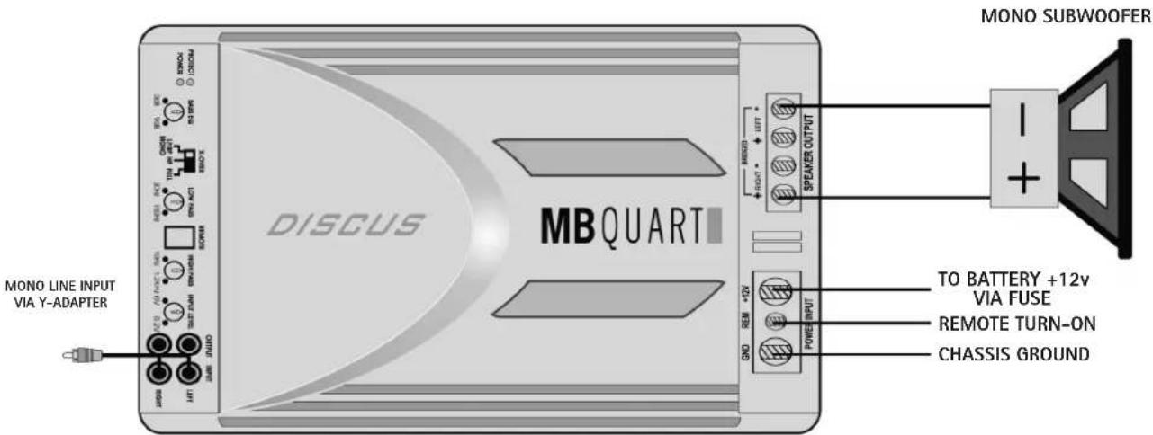
ENG
FEATURES:
• PROTECTION and POWER LED indicators
• Bass EQ: 45Hz bass boost from 0dB to 9dB
• X-OVER:
- LP/BP: Selects built in LOW PASS filter, variable from 30Hz to 150Hz
- HP: Selects built in HIGH PASS filter, variable from 10Hz to 1.2KHz
- FULL: Bypasses all crossovers for full frequency range operation
Note that the LOW PASS signal is MONO
- In the LP position, the HIGH PASS filter acts as a subsonic filter. When the
HP switch is higher adjusted than 150Hz, you can hear no sound -
When the LP mode is selected, a 0 to +9dB at 45Hz BASS EQ is active
-
The REMOTE jack enables a dash mount control for the BASS EQ in LP mode only
- INPUT LEVEL sensitivities are variable from 0.2volts to 6volts
- INPUT MODE: In the 2CH mode, all four channels are supplied signal from CH1/2 RCA jacks. In the 4CH mode, CH1/2 are supplied signal from CH1/2 RCA jacks and CH3/4 are supplied signal from CH3/4 RCA jacks.

• Each model is capable of 4ohms or 2ohms operation per channel, or 4ohms mono
4 CHANNEL FULL RANGE STEREO
- Interconnect cable checklist:
Connect the 4 inputs of the amplifier to a Radio/CD with quality RCA cables. - Crossover switch:
-1/2CH X-OVER: FULL
-3/4CH X-OVER: FULL
- Crossover frequency control checklist:
N/A for full range operation.
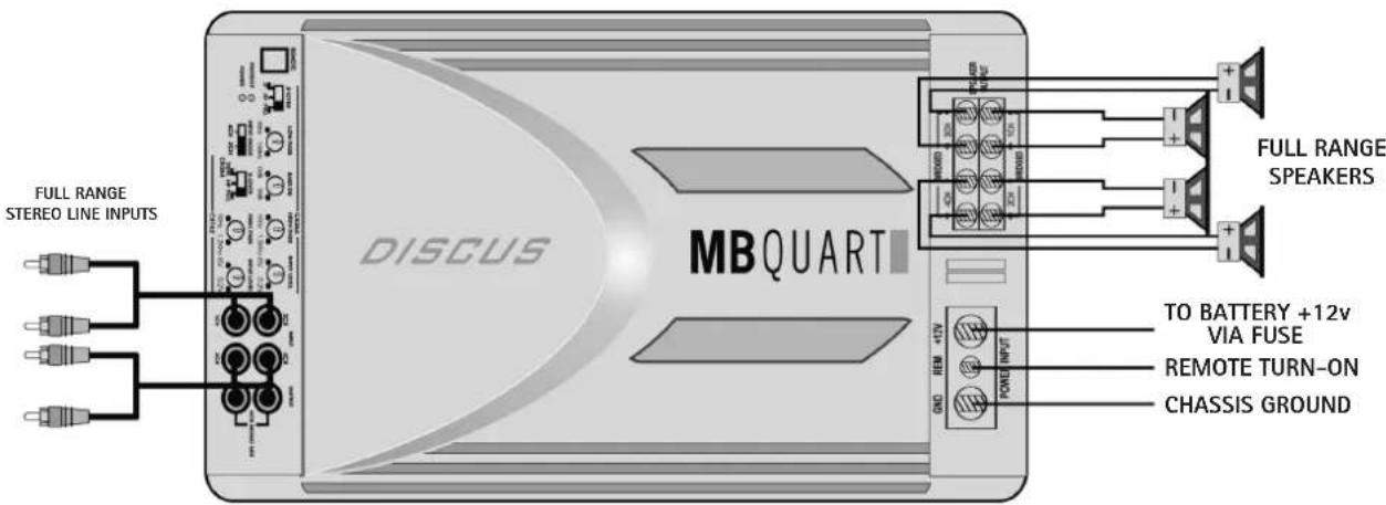
3 CHANNEL OPERATION
This illustration shows how to use your 4 channel amplifier as a 3 channel unit by taking advantage of the mono bridging capability on all Discus amplifiers.
- Interconnect cable checklist:
-1/2CH: Connect the inputs of channel pair1/2 to a suitable stereo source with quality RCA cables.
-3/4CH: Connect mono line input via Y-adapter from mono source or single Left or Right RCA from stereo source.
IMPORTANT: Do not connect the Left and Right stereo signals together to achieve a mono signal as this will damage the output stage of source and possibly the input stage of the amplifier.
- Crossover switch:
-CH1/2 X-OVER: FULL
-CH3/4 X-OVER: LP
- Input Mode:
4CH
- Line Level, Bass EQ, Low Pass & High Pass:
Refer the section "Setting up systems after installation for best performance." on page 2.
- Bass Remote Module:
Plug in the optional Remote Bass Module to the REMOTE jack and control the Bass EQ setting for CH3/4.
- Speaker Connections:
Connect the subwoofer- to 3CH- and the subwoofer+ to 4CH+ terminal. Connect the remaining speakers in standard stereo wiring to 1CH and 2CH.
IMPORTANT: Minimum final loudspeaker impedance must be not lower than
4ohms in mono operation and 2 ohms in stereo operation.

FEATURES:
• PROTECTION and POWER LED indicators
- The REMOTE jack enables a dash mount control for the BASS BOOST
- LOW PASS: Variable from 35Hz to 250Hz
• SUBSONIC FILTER: Variable from 15Hz to 35Hz
• BASS BOOST: 45Hz bass boost from 0dB to 9dB
- INPUT LEVEL sensitivities are variable from 0.2volts to 6volts
• Each model is capable of 1ohm minimum
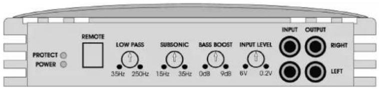
BASIC OPERATION
- Interconnect cable checklist:
Connect mono line input via Y-adapter from mono source or single
Left or Right RCA from stereo source.
IMPORTANT: Do not connect the Left and Right stereo signals
together to achieve a mono signal as this will damage the output
stage of source and possibly the input stage of the amplifier.
- Use at least 16 gauge speaker wiring. These amplifiers feature dual speaker
terminals, simplifying the hookup of multiple speakers.
- Line Level, Bass EQ, Low Pass & Subsonic:
Refer the section "Setting up systems after installation for best performance."
- Bass Remote Module:
Plug in the optional Remote Bass Module to the REMOTE jack and control the Bass Boost setting.
IMPORTANT: Minimum final loudspeaker impedance must be not lower than 1ohm.
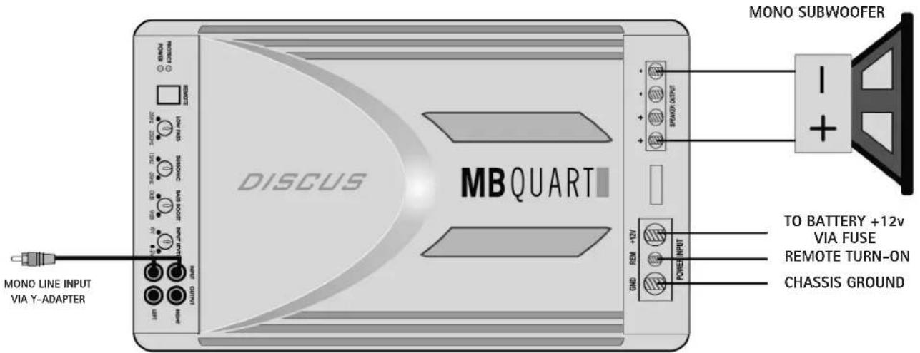

ENG
FEATURES:
• PROTECTION and POWER LED indicators
- The REMOTE jack enables a dash mount control for the BASS BOOST
• BALANCED INPUT: balanced MINI-DIN signal input
NOTE: DO not use this input with the RCA input at the same time.
- LOW PASS: Variable from 35Hz to 250Hz
• SUBSONIC FILTER: Variable from 15Hz to 35Hz
• PHASE: Variable from 0 to 180
• BASS BOOST: 45Hz bass boost from 0dB to 9dB
- INPUT LEVEL sensitivities are variable from 0.2volts to 6volts
• Each model is capable of 1ohm minimum
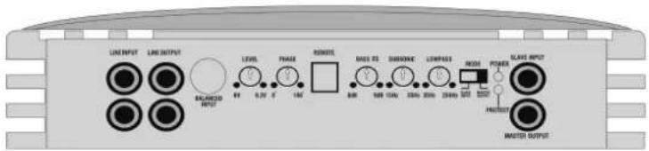
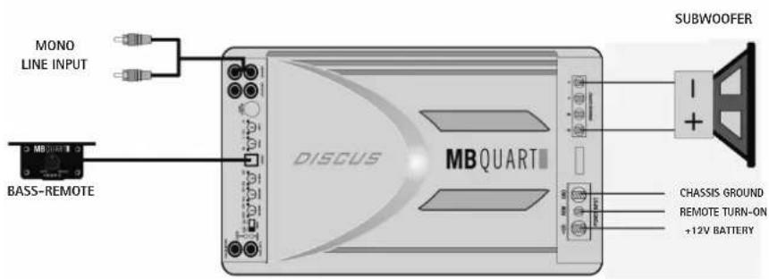
STANDARD OPERATION
1. Interconnect cable checklist:
Connect mono line input via Y-adapter from mono source or single Left or Right RCA from stereo source.
IMPORTANT: Do not connect the Left and Right stereo signals together to achieve a mono signal as this will damage the output stage of source and possibly the input stage of the amplifier.
- Use at least 1,5 sqmmspeaker wiring. These amplifiers feature dual speaker terminals, simplifying the hookup of multiple speakers.
3. Bass Remote Module:
Plug in the optional Remote Bass Module to the REMOTE jack and control the Bass Boost setting.
4. Mode-Switch:
The „MODE“ switch must be on „MASTER OUTPUT“ position.
IMPORTANT: Minimum final loudspeaker impedance must be not lower than 1ohm.

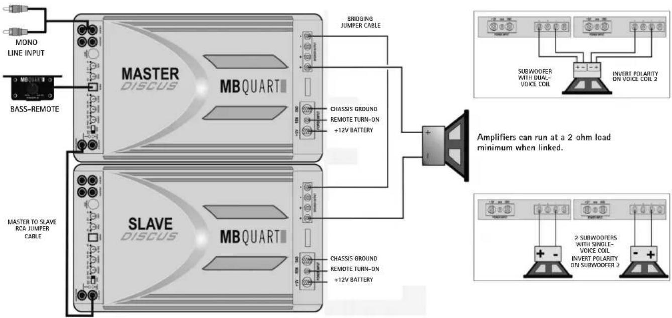
Connect mono line input via Y-adapter from mono source or single Left or Right RCA from stereo source into the „MASTER" amp.
- Interconnect cable checklist SLAVE:
Connect a mono line cable from „MASTER OUTPUT" of the „MASTER" amp with the „SLAVE INPUT" of the „SLAVE" amp.
- Mode Switch:
The „MODE“ switch of the „MASTER“ amp must be in position „MASTER OUTPUT“. The switch of the „SLAVE“ amp in position „SLAVE INPUT“.
4. Bass Remote Module:
Plug in the optional Remote Bass Module to the REMOTE jack of the "MASTER" amp and control the Bass Boost setting of both amps together.
IMPORTANT: Minimum final loudspeaker impedance must be not lower than 2ohm. Check the below featured connection figures.
flowchart
graph TD
    A["MONO LINE INPUT"] --> B["BASS-REMOTE"]
    B --> C["MASTER TO SLAVE RCA JUMPER CABLE"]
    C --> D["MASTER DISCUS MBQUART"]
    D --> E["BRIDGING JUMPER CABLE"]
    E --> F["CHASSIS GROUND REMOTE TURN-ON +12V BATTERY"]
    F --> G["+"]
    G --> H["Amplifiers can run at a 2 ohm load minimum when linked."]
    I["SUBWOOFER WITH DUAL-VOICE COIL"] --> J["INVERT POLARITY ON VOICE COIL 2"]
    K["2 SUBWOOFERS WITH SINGLE-VOICE COIL"] --> L["INVERT POLARITY ON SUBWOOFER 2"]
ENG
TROUBLE SHOOTING
The key to finding the problem in a misbehaving sound system is to isolate parts of that system in a logical fashion to track down the fault. Description of the Diagnostic system built into all MB Quart amplifiers:
The diagnostic system will shut down the amplifier, until reset by turning the head unit off, and back on. This state of affairs will be indicated by the front panel PROTECT LED lighting up under the following conditions:
1 - A short circuit on the loudspeaker leads.
2 - An internal amplifier fault that causes a DC offset on the loudspeaker output.
Should the amplifier go into diagnostic mode, simply disconnect all RCA and speaker leads, while keeping +12 volt, power ground and remote leads connected.
1 - Now turn the amplifier back on, and if the diagnostic LED lights, the amplifier has an internal fault.
2 - If not, plug the RCA cables back, and reset the amplifier. If it goes into diagnostic now, the fault lies in the input, either with bad cables or source unit.
3 - If the amplifier seems fine with RCA cables plugged in, connect the speakers, one at a time, and if one of the speakers or its wiring is faulty, it will activate the diagnostic system.
Amplifier heatsink overheating
The amplifiers will shut down when the heatsink temperature reaches 80^ C, and turn back on once the unit has cooled down below that point.
Causes of overheating:
1 - Inadequate cooling - relocate or remount to provide better natural airflow over the fins.
2 - Driving high power levels into low impedances - back off on the volume control, and/or make sure you are not loading the amplifier with less than the recommended loudspeaker impedance.
Low output power
1 - Check that level controls have been set up properly.
2 - Make sure that the battery voltage, as measured at the amplifier's +12 volt and ground terminals, is 11 volts or more.
3 - Check all +12 volt and ground connections.
Fuses blowing
1 - The use of loudspeaker impedances below the recommended minimums will draw more current - check.
2 - A short on the main +12 volt cable from the battery to the vehicle chassis will cause the main fuse to blow.
3 - If an amplifier fuse blows continually, with only +12 volt, ground and remote leads connected, the amplifier may be faulty.
System does not turn on
1 - Check all fuses.
2 - Check all connections.
3 - Measure the +12 volt and remote turn on voltages at the amplifier terminals. If these are non existent or low, take voltage measurements at fuse holders, distribution blocks, the head unit's +12 volt and remote leads to localize the problem.
Noise problems
System noise can be divided into two categories, hiss, and electrical interference.
Hiss, or white noise
1 - High levels of white noise usually occurs when amplifier level controls are turned up too high - readjust according to the procedures in section "Setting up systems after installation for best performance"
2 - Another major problem that can cause excessive hiss, is a noisy head unit - unplug the amplifier input RCA cables, and if the hiss level reduces, the source unit is at fault.
Electrical interference
The inside of an automobile is a very hostile electrical environment. The multitude of electrical systems, such as the ignition system, alternator, fuel pumps, air conditioners, to mention just a few, create radiated electrical fields, as well as noise on the +12 volt supply and ground. Remember to isolate the problem - first unplug amplifier input RCA cables, if the noise is still present, check the speaker leads, if not, plug the RCA's back, and investigate the source driving the amplifier, one component at a time.
A ticking or whine that changes with engine RPM
1 - This problem could be caused by radiation pickup of RCA cables too near to a fuel pump or a distributor, for instance, - relocate cables.
2 - Check that the head unit ground is connected straight to the vehicle chassis, and does not use factory wiring for ground.
3 - Try to supply the head unit with a clean +12 volt supply directly from the battery +, instead of using a supply from the in dash wiring/fusebox.
A constant whine
This type of noise can be more difficult to pinpoint, but is usually caused by some kind of instability, causing oscillations in the system.
1 - Check all connections, especially for good grounds.
2 - Make sure that no speaker leads are shorting to exposed metal on the vehicle chassis.
3 - RCA cables are notorious for their problematic nature, so check that these are good, in particular the shield connections.
| SPECIFICATIONS | 2-CHANNEL | 4-CHANNEL | MONO | |||
| DSC2150 | DSC480 | DSC4125 | DSC500.1 | DSC1000.1 | DSC1500.1D | |
| Output Power Rating Watts RMS | ||||||
| 4-Ohms 150 x 2 80 x 4 125 x 4 150 x 1 350 x 1 600 x 1 | ||||||
| 2-Ohms 300 x 2 160 x 4 250 x 4 250 x 1 500 x 1 1000 x 1 | ||||||
| 1-Ohm 500 x 1 1000 x 1 1500 x 1 | ||||||
| Mono Bridge at 4-Ohms 600 x 1 320 x 2 500 x 2 | ||||||
| Power Supply PWM PWM PWM PWM | PWM | Mosfet | Mosfet | Mosfet | Mosfet | Mosfet |
| Output Power Circuit Configuration | ||||||
| Miscellaneous Spec | ||||||
| Soft Start Sound | Yes | Yes | Yes | Yes | Yes | Yes |
| Frequency Response-3dB | 10Hz - 30KHz | 10Hz - 30KHz | 10Hz - 30KHz | 10Hz - 30KHz | 10Hz - 30KHz | 10Hz - 30KHz |
| Damping Factor | >180 | >180 | >180 | >200 | >200 | >200 |
| S/N Ratio (A-Weight) | >92dB | >92dB | >92dB | >95dB | >95dB | >95dB |
| THD & N | 0.05% | 0.05% | 0.05% | 0.10% | 0.10% | 0.10% |
| Channel Separation | >80dB | >80dB | >80dB | - | - | - |
| Variable Input Level Control | 0.2V-6.0V | 0.2V-6.0V | 0.2V-6.0V | 0.2V-6.0V | 0.2V-6.0V | 0.2V-6.0V |
| Input Impedance | 47kOhms | 47kOhms | 47kOhms | 47kOhms | 47kOhms | 47kOhms |
| Diagnostic Indicator (power: green / protect: red) | Power/Protect | Power/Protect | Power/Protect | Power/Protect | Power/Protect | Power/Protect |
| Protection (DC, Short, Thermal, Overload) | Yes | Yes | Yes | Yes | Yes | Yes |
| Crossover Operation | ||||||
| Crossover S/W for 1+2 channel | LP/HP/FULL | DUPE CH3+4/HP/FULL | DUPE CH3+4/HP/FULL | - | - | - |
| Variable Hi-Pass / Subsonic Filter | 10Hz - 1.2KHz | 10Hz - 1.2KHz | 10Hz - 1.2KHz | - | - | - |
| Variable Low-Pass (Mono 24dB) | 30Hz - 150Hz | - | - | 35Hz - 250Hz | 35Hz - 250Hz | 35Hz - 250Hz |
| Variable Subsonic Filter | Ncin | - | - | 15Hz - 35Hz | 15Hz - 35Hz | 15Hz - 35Hz |
| Bass Boost at 45Hz | 0 - 9dB | - | - | 0 - 9dB | 0 - 9dB | 0 - 9dB |
| Phase-Shift | - | - | - | - | - | 0 - 180 |
| Crossover S/W for 3+4 channel | - | LP/HP/FULL | LP/HP/FULL | - | - | - |
| Variable Hi-Pass | - | 10Hz - 1.2KHz | 10Hz - 1.2KHz | - | - | - |
| Variable Low-Pass (Mono 24dB) | - | 30Hz - 150Hz | 30Hz - 150Hz | - | - | - |
| Variable Subsonic Filter | - | - | - | - | - | - |
| Bass Boost at 45Hz | - | 0 - 9dB | 0 - 9dB | - | - | - |
| Line Output | Full Range | Full Range | Full Range | Full Range | Full Range | Full Range |
| RCA Jack | Yes | Yes | Yes | Yes | Yes | Yes |
| Phone Jack for Remote Control | Yes | Yes | Yes | Yes | Yes | Yes |
| Bass Boost Remote Control Module | Optional | Optional | Optional | Yes | Yes | Yes |
| Power Terminal | 20 sqmm | 20 sqmm | 20 sqmm | 20 sqmm | 20 sqmm | 25 sqmm |
| Speaker Terminal | 5 sqmm | 3.5 sqmm | 3.5 sqmm | 5 sqmm | 5 sqmm | 5 sqmm |
| Fuse Size | 60 A | 30 A x 2 | 100 A | 70 A | 60 A x 2 | 70 A x 2 |
| Dimensions Length x Width x Height (mm) | 380 x 240 x 68 | 360 x 240 x 68 | 400 x 240 x 68 | 400 x 240 x 68 | 500 x 240 x 68 | 360 x 240 x 68 |
| Note: Features subject to change with out note | ||||||
Technical specifications are subject to change! Errors are reserved!
For damages on the vehicle and the device, caused by handling errors of the device, we can't assume liability.
All MB QUART Amplifiers are tagged with a individual serialnumber, which will be registered for statistic and service conditional purposes.
All MB QUART Amplifiers are tagged with a E-Certification Number and also a CE-Certification Mark. Thereby these devices are certified for the use inside vehicles inside the European Union (EU).
WARRANTY DISCLAIMER
The limited warranty comply with legal regulations. Failures or damages caused by overload, improper use or by using the product for competitions are not covered by the warranty.
Please return the defective product only with a valid proof of purchase and a detailed malfunction description.

bar
| Category | Value | |---|---| | 1 | 0.5 | | 2 | 0.6 | | 3 | 0.7 | | 4 | 0.8 | | 5 | 0.9 | | 6 | 1.0 | | 7 | 0.9 | | 8 | 0.8 | | 9 | 0.7 | | 10 | 0.6 | | 11 | 0.5 | | 12 | 0.4 | | 13 | 0.3 | | 14 | 0.2 | | 15 | 0.1 | | 16 | 0.2 | | 17 | 0.3 | | 18 | 0.4 | | 19 | 0.5 | | 20 | 0.6 | | 21 | 0.7 | | 22 | 0.8 | | 23 | 0.9 | | 24 | 1.0 | | 25 | 0.9 | | 26 | 0.8 | | 27 | 0.7 | | 28 | 0.6 | | 29 | 0.5 | | 30 | 0.4 | | 31 | 0.3 | | 32 | 0.2 | | 33 | 0.1 | | 34 | 0.2 | | 35 | 0.3 | | 36 | 0.4 | | 37 | 0.5 | | 38 | 0.6 | | 39 | 0.7 | | 40 | 0.8 | | 41 | 0.9 | | 42 | 1.0 | | 43 | 0.9 | | 44 | 0.8 | | 45 | 0.7 | | 46 | 0.6 | | 47 | 0.5 | | 48 | 0.4 | | 49 | 0.3 | | 50 | 0.2 | | 51 | 0.1 | | 52 | 0.2 | | 53 | 0.3 | | 54 | 0.4 | | 55 | 0.5 | | 56 | 0.6 | | 57 | 0.7 | | 58 | 0.8 | | 59 | 0.9 | | 60 | 1.0 | | 61 | 0.9 | | 62 | 0.8 | | 63 | 0.7 | | 64 | 0.6 | | 65 | 0.5 | | 66 | 0.4 | | 67 | 0.3 | | 68 | 0.2 | | 69 | 0.1 | | 70 | 0.2 | | 71 | 0.3 | | 72 | 0.4 | | 73 | 0.5 | | 74 | 0.6 | | 75 | 0.7 | | 76 | 0.8 | | 77 | 0.9 | | 78 | 1.0 | | 79 | 0.9 | | 80 | 0.8 | | 81 | 0.7 | | 82 | 0.6 | | 83 | 0.5 | | 84 | 0.4 | | 85 | 0.3 | | 86 | 0.2 | | 87 | 0.1 | | 88 | 0.2 | | 89 | 0.3 | | 90 | 0.4 | | 91 | 0.5 | | 92 | 0.6 | | 93 | 0.7 | | 94 | 0.8 | | 95 | 0.9 | | 96 | 1.0 | | Note: The actual values in the 'Value' column are not provided in the code image, so they are estimated based on the visual representation of the 'Value' in the 'Bar Chart'.MBQUART®
MOBILE AUDIO


- DEU
- INSTALLATION
- Allgemeines:
- Hochpass (High Pass):
- Tiefpass (Low Pass):
- Power and ground connections:
- Safe connection sequence:
- Power up the system:
- SETTING UP SYSTEMS AFTER INSTALLATION FOR BEST PERFORMANCE
- General:
- High Pass:
- Bass EQ:
- Low Pass:
- Level Control Setup:
- If you are not sure what the Radio output sensitivity is, follow these general guide lines:
- or 3 way active systems (all):
- ENG
- FEATURES:
- FULL RANGE STEREO
- MONO/BRIDGED
- CHANNEL FULL RANGE STEREO
- CHANNEL OPERATION
- BASIC OPERATION
- STANDARD OPERATION
- Interconnect cable checklist:
- Bass Remote Module:
- Mode-Switch:
- Bass Remote Module:
- TROUBLE SHOOTING
- Amplifier heatsink overheating
- Low output power
- Fuses blowing
- System does not turn on
- Noise problems
- Hiss, or white noise
- Electrical interference
- A ticking or whine that changes with engine RPM
- A constant whine
- WARRANTY DISCLAIMER
- MBQUART®
Brand : MB QUART
Model : DSC480
Category : Car radio