
UDX-W40 - Projector Barco - Free user manual and instructions
Find the device manual for free UDX-W40 Barco in PDF.


| Product Type | Video Projector (Laser Phosphor) |
| Model | Barco UDX-W40 |
| Resolution | WUXGA (1920 x 1200) |
| Brightness | 40,000 lumens |
| Contrast Ratio | Dynamic contrast (DynaBlack) |
| Light Source | Laser phosphor |
| Weight (without lens & rigging frame) | Approx. 90 kg (198 lbs) |
| Power Requirements | 120-160V / 200-240V (+/-10%), 20A, 50-60Hz |
| Power Consumption | Refer to manual for exact values |
| Input Options | HDMI, DisplayPort 1.2, HDBaseT, SFP, SDI, Quad Combo |
| 3D Support | Active and Passive Stereo |
| Warping & Blending | Yes (multiple blending zones, warping files) |
| Color Management | RealColor P7 |
| Lens Compatibility | Barco TLD+ series (zoom, fixed) |
| Remote Control | Pulse RCU with IR, XLR, and mini-jack connectivity |
| Network Control | LAN (10/100 base-T), optional WiFi/GSM |
| Cooling System | Liquid cooling with Mono-ethylene glycol solution |
| Maintenance | Air filter cleaning/replacement, lens cleaning, software updates |
| Safety Classification | RG3 (Risk Group 3) per IEC 62471-5:2015 |
| Hazard Distance | Varies with lens; see manual for table |
| Operating Temperature | 0°C to 40°C (32°F to 104°F) |
| Humidity | 0% to 80% RH (non-condensing) |
| Compliance | FCC Class A, CE, UKCA, China RoHS, Taiwan RoHS, Turkey RoHS |
Frequently Asked Questions - UDX-W40 Barco
User questions about UDX-W40 Barco
0 question about this device. Answer the ones you know or ask your own.
Ask a new question about this device
Download the instructions for your Projector in PDF format for free! Find your manual UDX-W40 - Barco and take your electronic device back in hand. On this page are published all the documents necessary for the use of your device. UDX-W40 by Barco.
USER MANUAL UDX-W40 Barco
natural_image
Exterior view of a black projector unit with lens and control knobs (no visible text or symbols)User manual
Product revision
Software Revision: 2.2
Barco NV
Beneluxpark 21, 8500 Kortrijk, Belgium
www.barco.com/en/support
www.barco.com
Registered office: Barco NV
President Kennedypark 35, 8500 Kortrijk, Belgium
www.barco.com/en/support
www.barco.com
Copyright ©
All rights reserved. No part of this document may be copied, reproduced or translated. It shall not otherwise be recorded, transmitted or stored in a retrieval system without the prior written consent of Barco.
Changes
Barco provides this manual 'as is' without warranty of any kind, either expressed or implied, including but not limited to the implied warranties or merchantability and fitness for a particular purpose. Barco may make improvements and/or changes to the product(s) and/or the program(s) described in this publication at any time without notice.
This publication could contain technical inaccuracies or typographical errors. Changes are periodically made to the information in this publication; these changes are incorporated in new editions of this publication.
The latest edition of Barco manuals can be downloaded from the Barco web site www.barco.com or from the secured Barco web site https://www.barco.com/en/signin.
Trademarks
Brand and product names mentioned in this manual may be trademarks, registered trademarks or copyrights of their respective holders. All brand and product names mentioned in this manual serve as comments or examples and are not to be understood as advertising for the products or their manufacturers.
Product Security Incident Response
As a global technology leader, Barco is committed to deliver secure solutions and services to our customers, while protecting Barco's intellectual property. When product security concerns are received, the product security incident response process will be triggered immediately. To address specific security concerns or to report security issues with Barco products, please inform us via contact details mentioned on https://www.barco.com/psirt. To protect our customers, Barco does not publicly disclose or confirm security vulnerabilities until Barco has conducted an analysis of the product and issued fixes and/or mitigations.
Patent protection
Please refer to www.barco.com/about-barco/legal/patents.
Guarantee and Compensation
Barco provides a guarantee relating to perfect manufacturing as part of the legally stipulated terms of guarantee. On receipt, the purchaser must immediately inspect all delivered goods for damage incurred during transport, as well as for material and manufacturing faults Barco must be informed immediately in writing of any complaints.
The period of guarantee begins on the date of transfer of risks, in the case of special systems and software or the date of commissioning, at latest 30 days after the transfer of risks. In the event of justified notice of complaint, Barco can repair the fault or provide a replacement at its own discretion within an appropriate period. If this measure proves to be impossible or unsuccessful, the purchaser can demand a reduction in the purchase price or cancellation of the contract. All other claims, in particular those relating to compensation for direct or indirect damage, and also damage attributed to the operation of software as well as to other services provided by Barco, being a component of the system or independent service, will be deemed invalid provided the damage is not proven to be attributed to the absence of properties guaranteed in writing or due to the intent or gross negligence or part of Barco.
If the purchaser or a third party carries out modifications or repairs on goods delivered by Barco, or if the goods are handled incorrectly, in particular if the systems are operated incorrectly or if, after the transfer of risks, the goods are subject to influences not agreed upon in the contract, all guarantee claims of the purchaser will be rendered invalid. Not included in the guarantee coverage are system failures which are attributed to programs or special electronic circuitry provided by the purchaser, e.g. interfaces. Normal wear as well as normal maintenance are not subject to the guarantee provided by Barco either.
The environmental conditions as well as the servicing and maintenance regulations specified in this manual must be complied with by the customer.
Disclaimer on GUI images used in this manual
The GUI images in this manual are example illustrations and should be treated as such. While the name of the projector displayed in the illustrations may be different from the projector model you are currently using, the menu lay-out and functionality is identical.
Disclaimer for camera usage
Barco provides a kit with a laser range finder and USB camera to help measure the distance from the front of the projector to the projected surface and to help monitor the performance of the projector. Barco disclaims any liability for any use of the USB camera outside this intended use.
Disclaimer for network usage
Barco highly recommends to install the projector in a closed network environment to minimize the risk of leaking, hacking or corrupting of company confidential information; commercial sensitive information and/or personal data. Furthermore, strengthen your network security to protect the projector against unauthorized access by third parties. To the maximum extent permitted by law, Barco disclaims any liability for the use of the projector in an open network environment.
Table of contents
1 Safety information 9
1.1 General considerations 10
1.2 Safety training to be provided by the installer.... 11
1.3 Important safety instructions....12
1.4 Product safety labels....16
1.5 High Brightness precautions: Hazard Distance....16
1.6 HD for fully enclosed projection systems....18
1.7 HD in function of modifying optics 20
1.8 Radio equipment (optional)....20
1.9 Compliance 21
1.10 Download Product Manual 21
2 Getting started 23
2.1 Getting to know the projector 24
2.2 Power on projector 25
2.3 Start image projection 26
2.4 Switching to ready mode 29
2.5 Power off projector 29
3 Pulse Remote Control Unit 31
3.1 Pulse RCU, battery installation 32
3.2 Pulse RCU, protocol setup 33
3.3 Pulse RCU, function of the on/off button....33
3.4 Using the RCU 34
3.5 Pulse RCU, Functionality overview 35
3.6 Pulse RCU, function of the "button pressed indicator" 35
3.7 Pulse RCU, function of the "RGB filter" button 36
3.8 Displaying and Programming addresses into the RCU 36
3.9 Using the XLR connector of the RCU 36
3.10 Using the mini-jack connector of the RCU 37
3.11 Pulse RCU, silicone protection sleeve (optional) 37
4 Input & Communication 39
4.1 Introduction....40
4.2 Local Keypad and LCD panel 40
4.3 LCD touch panel 41
4.4 Communication connections 42
4.5 LED and Button indication chart....44
4.6 Pulse Quad Combo input Mk II 45
4.7 Pulse Quad Combo input Mk I 46
4.8 Pulse Quad DP 1.2 input 47
4.9 Pulse SFP input 48
5 GUI – Introduction......49
5.1 Overview 50
5.2 Navigation....53
5.3 Test Patterns....55
6 GUI – Source 57
6.1 Displaying a single source 58
6.2 Displaying multiple sources: Stitched layouts....58
6.3 Connector Settings 60
7 GUI – Image 63
7.1 Setting image levels manually....64
7.2 Adjusting the sharpness....65
7.3 Adjusting the gamma correction....66
7.4 Setting the desired Gamma type....67
7.5 Digital Shift & Zoom 69
7.6 RealColor P7 73
7.7 Setting the output resolution....75
7.8 Displaying HDR content 76
7.9 Dynamic contrast 77
8 GUI – Installation 79
8.1 Configuring the lens, optical zoom-focus 80
8.2 Configuring the lens, shift 80
8.3 Configuring the lens, dynamic focus 81
8.4 Configuring the lens, Shift to center 82
8.5 Configuring the lens, tilt sensor....83
8.6 Laser ranging 84
8.7 Manipulating the rigging frame 85
8.8 Manipulating the rigging frame, center position 87
8.9 Orientation 87
8.10 Scaling modes 88
8.11 Warping 89
8.11.1 Warping-On/Off 90
8.11.2 Warping – Screen Size 90
8.11.3 Warping - 4 corners adjustment....93
8.11.4 Warping-Bow 95
8.11.5 Warping – Warp files 99
8.11.6 Warping – Latency control in a multi projector setup 101
8.12 Blending & masking....102
8.12.1 Basic blend 103
8.12.2 Blend & Blend mask 105
8.12.3 Blend Files 107
8.12.4 Basic black level adjustment 108
8.12.5 RGB gain adjustment....110
8.12.6 Black Level Files.... 111
8.13 Illumination 112
8.14 3D projection ....113
8.14.1 Active Stereo & Passive Stereo....113
8.14.2 Setup process 3D projection .....114
8.14.3 Connection possibilities....114
8.14.4 3D Setup....115
9 GUI – Projector profiles 117
9.1 Saving the current projector settings in a profile 118
9.2 Assigning a created projector profile to a preset.... 120
9.3 Deleting a projector profile....121
10 GUI – System Settings 123
10.1.1 Broadcast address 124
10.1.2 Projector address....124
10.1.3 IR sensors 125
10.3.1 Introduction to a Network connection 127
10.3.2 Wired IP address set up 128
10.3.3 Wireless IP address set up 130
10.3.4 LAN over HDBaseT ^TM IP address set up.... 133
10.1 Remote control 124
10.2 Host name - custom projector name setup.... 126
10.3 Communication, LAN setup 127
10.4 DMX....135
10.5 Front XLR output voltage control 137
10.6 GSM configuration.... 138
10.7 Changing the User Interface language 139
10.8 Themes....139
10.9 Units (measurement) system setup.... 140
10.10 Controlling the backlight of the LCD Display 141
10.11 Date and time setup - manually 141
10.12 Date and time setup - automatically 142
10.13 Power saving settings – Standby mode 144
10.14 Lens features.... 145
10.15 Factory reset.... 146
10.16 Lens Calibration....149
10.17 Flex brightness 151
10.18 Rigging frame Calibration 152
10.19 Electronic Convergence 153
10.20 Setting up the external cooler on a UDX.... 154
10.21 Capture mode 155
10.22 Login to advanced settings.... 156
10.23 List of open source licenses.... 156
11 Advanced Settings 159
11.1 Remote access – Enable source preview.... 160
11.2 Remote access – Enable camera preview 161
11.3 Advanced Settings – Color 162
11.4 Advanced Settings – Statistics 163
11.5 Checking the status of the Laser Banks.... 164
11.6 Advanced settings – Tilt sensor calibration.... 165
12 GUI – Status menu.... 167
12.1 Status menu overview 168
13 Projector maintenance 171
13.1 Software update.... 172
13.2 Cleaning the lens 173
13.3 Cleaning the exterior of the projector.... 174
A Specifications 175
A.1 Specifications of the UDX-4K40 176
A.2 Specifications of the UDX-4K32 177
A.3 Specifications of the UDX-4K26 179
A.4 Specifications of the UDX-4K22 180
A.5 Specifications of the UDX-W40....182
A.6 Specifications of the UDX-W32....184
A.7 Specifications of the UDX-W26....185
A.8 Specifications of the UDX-W22....187
A.9 Specifications of the UDX-U45LC 188
A.10 Specifications of the UDX-U40....190
A.11 Specifications of the UDX-U32....191
A.12 Specifications SDI inputs.... 193
A.13 Specifications HDMI inputs 194
A.14 Specifications HDBaseT inputs.... 194
A.15 Specifications DisplayPort 1.2 inputs 195
A.16 Specifications SFP inputs 197
B Video timing tables....199
B.1 Overview video timings....200
B.2 Overview video timings SDI Inputs 201
B.3 Overview video timings HDMI 2.0 inputs....202
B.4 Overview video timings DisplayPort 1.2 inputs 204
B.5 Overview video timings HDBaseT inputs 206
C DMX chart 209
C.1 DMX chart input board positioning 210
C.2 DMX chart, Basic 210
C.3 DMX chart, Extended....211
D Regulatory information 215
D.1 Product compliance 216
D.2 China RoHS compliance....217
D.3 Taiwan RoHS compliance 218
D.4 Turkey RoHS compliance....219
D.5 Disposal information....219
D.6 Contact information....220
D.7 Production address....220
E WiFi & GSM compliance information 221
E.1 Compliance FCC 222
E.2 Compliance IC 222
E.3 KCC Certification....223
Glossary 225
List of tools 227
Index 229
Safety information
1
1.1 General considerations 10
1.2 Safety training to be provided by the installer 11
1.3 Important safety instructions....12
1.4 Product safety labels.... 16
1.5 High Brightness precautions: Hazard Distance....16
1.6 HD for fully enclosed projection systems.... 18
1.7 HD in function of modifying optics 20
1.8 Radio equipment (optional) 20
1.9 Compliance....21
1.10 Download Product Manual 21
About this document
Read this document attentively. It contains important information to prevent personal injury while installing and using the UDX projector. Furthermore, it includes several cautions to prevent damage to the UDX projector. Ensure that you understand and follow all safety guidelines, safety instructions and warnings mentioned in this chapter before installing the UDX projector.
Clarification of the term "UDX" used in this document
When referring in this document to the term "UDX" means that the content is applicable for following Barco products:
- UDX 4K22, UDX 4K26, UDX 4K32, UDX 4K40, UDX 4K45 LC, UDX U32, UDX U40, UDX U45 LC, UDX W22, UDX W26, UDX W32, UDX W40, UDX W45 LC
Model certification name
- UDX

Barco provides a guarantee relating to perfect manufacturing as part of the legally stipulated terms of guarantee. Observing the specification mentioned in this chapter is critical for projector performance. Neglecting this can result in loss of warranty.
1.1 General considerations

WARNING: Be aware of suspended loads.

WARNING: Wear a hard hat to reduce the risk of personal injury.

WARNING: Be careful while working with heavy loads.

WARNING: Mind your fingers while working with heavy loads.

WARNING: In case of optical radiation emergency, please disconnect the device from the mains current; this by employing the mains switch. In case the mains switch is not easily accessible, the projectors shall be disconnected by other means for example the mains junction box.
It is advised to employ the shutter or select a black image on the projector in order to reduce the risk of the emergency.
General safety instructions
- Before operating this equipment please read this manual thoroughly and retain it for future reference.
• Installation and preliminary adjustments should be performed by qualified Barco personnel or by authorized Barco service dealers. - All warnings on the projector and in the documentation manuals should be adhered to.
- All instructions for operating and use of this equipment must be followed precisely.
- All local installation codes should be adhered to.
Notice on safety
This equipment is built in accordance with the requirements of the applicable international safety standards. These safety standards impose important requirements on the use of safety critical components, materials and insulation, in order to protect the user or operator against risk of electric shock and energy hazard and having access to live parts. Safety standards also impose limits to the internal and external temperature rises, radiation levels, mechanical stability and strength, enclosure construction and protection against the risk of fire. Simulated single fault condition testing ensures the safety of the equipment to the user even when the equipment's normal operation fails.
Notice on optical radiation
This projector embeds extremely high brightness (radiance) lasers; this laser light is processed through the projector's optical path. Native laser light is not accessible by the end user in any use case. The light exiting the projection lens has been diffused within the optical path, representing a larger source and lower radiance value than native laser light. Nevertheless the projected light represents a significant risk for the human eye and skin when exposed directly within the beam. This risk is not specifically related to the characteristics of laser light but solely to the high thermal induced energy of the light source; which is equivalent with lamp based systems.
Thermal retinal eye injury is possible when exposed within the Hazard Distance (HD). The HD is defined from the projection lens surface towards the position of the projected beam where the irradiance equals the maximum permissible exposure as described in the chapter "Hazard Distance".

WARNING: No direct exposure to the beam within the hazard distance shall be permitted, RG3 (Risk Group 3) IEC EN 62471-5:2015

CAUTION: Use of controls or adjustments or performance of procedures other than those specified herein may result in hazardous radiation exposure.
Notice on laser radiation
The laser distance meter that is optional equipment for this projector can emit a class 2 laser ranging beam of 0.95 mW / 638 nm. When installed correctly, this distance meter is located on the front side of the projector (see Image 1–1). The laser beam can be enabled by either pressing the button on the equipment, via the projector menu, or via the projector software. Thermal retinal eye injury is possible when staring into the laser ranging beam.
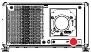
natural_image
Front view of an electronic device with a circular component and a red button, no visible text or symbolsImage 1-1 Location of the laser distance meter

WARNING: Laser Radiation — Do not stare into laser ranging beam, Class 2 IEC EN 60825-1:2014 See the product safety manual for details.
Users definition
Throughout this manual, the term SERVICE PERSONNEL refers to persons having appropriate technical training and experience necessary to be knowledgeable of potential hazards to which they are exposed (including, but not limited to HIGH VOLTAGE ELECTRIC and ELECTRONIC CIRCUITRY and HIGH BRIGHTNESS PROJECTORS) in performing a task, and of measures to minimize the potential risk to themselves or other persons. The term USER and OPERATOR refers to any person other than SERVICE PERSONNEL, AUTHORIZED to operate professional projection systems.
The UDX projector is intended "FOR PROFESSIONAL USE ONLY" by AUTHORIZED PERSONNEL familiar with potential hazards associated with high voltage, high intensity light beams and high temperatures generated by the light source and associated circuits. Only qualified SERVICE PERSONNEL, knowledgeable of such risks, are allowed to perform service functions inside the product enclosure.
1.2 Safety training to be provided by the installer
Users definition
The UDX projector is intended for persons who have been instructed and trained by a skilled person (installer or service personnel) to identify energy sources that may cause injury and to take precautions to avoid unintentional contact with or exposure to those energy sources.
The skilled person must instruct the user about:
- High intensity light beam. The user must respect the exclusion zone, based on the light beam Hazard Distance (HD).
- Dangerous energy sources inside the projector. The user is not allowed to remove any cover from the projector.
- The installation, maintenance or service is for skilled persons only.
• The requirements for a restricted access location, an exclusion zone and a restriction zone.
Restricted access location
To protect untrained persons and children, the projector must be installed in a restricted access location. The definition of a restricted access location is a location for equipment where both of the following paragraphs apply:
- Access can only be gained by skilled persons (installer or service personnel) or persons who have been instructed and trained by a skilled person. The persons must have been instructed about the reasons for the restriction applied to the location and about the precautions that shall be taken.
- Access is only possible through the use of the tool or lock and key, or other means of security, and is controlled by the authority responsible for the location.
Why a restricted access location: this is an RG3 product. Based on international requirements, no person is allowed to enter the projected beam within the zone between the projection lens and the related Hazard
Distance (HD). This shall be physically impossible by creating sufficient separation height and width or by placing optional barriers. Within the restricted area operator training is considered sufficient. The applicable separation heights and widths are discussed in "High Brightness precautions: Hazard Distance", page 16.
Exclusion zone
The projector radiates heat on its external surfaces and from ventilation ducts during normal operation.
Exposing flammable or combustible materials into close proximity of this projector could result in the spontaneous ignition of that material, resulting in a fire. For this reason, it is absolutely necessary to leave an exclusion zone around all external surfaces of the projector whereby no flammable or combustible materials are present:
- The exclusion zone must not be less than 40 cm (16 in).
Restriction zone
To protect untrained users and children against high intensity light beams, the light beam Hazard Distance (HD) shall be taken into account.
1.3 Important safety instructions
To prevent the risk of electrical shock
- This product should be operated from a mono phase AC power source. Ensure that the mains voltage and capacity matches the projector electrical ratings (120-160V / 200-240V (+/- 10%), 20A, 50-60Hz). If you are unable to install the AC requirements, contact your electrician. Do not defeat the purpose of the grounding.
- This apparatus must be grounded (earthed) via the supplied 3 conductor AC power cable. If you are unable to insert the plug into the outlet, contact your electrician to replace your obsolete outlet. Do not defeat the purpose of the grounding-type plug.
- Do not allow anything to rest on the power cord. Do not locate this product where persons will walk on the cord. To disconnect the cord, pull it out by the plug. Never pull the cord itself.
- Use only the power cord supplied with your device. While appearing to be similar, other power cords have not been safety tested at the factory and may not be used to power the device. For a replacement power cord, contact your dealer.
- Do not operate the projector with a damaged cord. Replace the cord.
- Do not operate the projector if the projector has been dropped or damaged - until it has been examined and approved for operation by qualified service personnel.
- Position the cord so that it will not be tripped over, pulled, or contact hot surfaces.
- If an extension cord is necessary, a cord with a current rating at least equal to that of the projector should be used. A cord rated for less amperage than the projector may overheat.
- Never push objects of any kind into this product through cabinet slots as they may touch dangerous voltage points or short out parts that could result in a risk of fire or electrical shock.
- Do not expose this projector to rain or moisture.
- Do not immerse or expose this projector in water or other liquids.
- Do not spill liquid of any kind on this projector.
- Should any liquid or solid object fall into the cabinet, unplug the set and have it checked by qualified service personnel before resuming operations.
- Do not disassemble this projector, always take it to qualified service personnel when service or repair work is required.
- Do not use an accessory attachment which is not recommended by the manufacturer.
- Lightning - For added protection for this video product during a lightning storm, or when it is left unattended and unused for long periods of time, unplug it from the wall outlet. This will prevent damage to the device due to lightning and AC power-line surges.
To prevent personal injury
- To prevent injury and physical damage, always read this manual and all labels on the system before powering the projector or adjusting the projector.
-
To prevent injury, take note of the weight of the projector. Minimum 2 persons are needed to carry the projector. The projector weights about ± 90 kg ( ± 198 lbs) without lens and rigging frame.
-
To prevent injury, ensure that the lens and all covers are correctly installed. See installation procedures.
- Warning: high intensity light beam. NEVER look into the lens! High luminance could result in damage to the eye.
- Warning: extremely high brightness projector: This projector embeds extremely high brightness (radiance) lasers; this laser light is processed through the projectors optical path. Native laser light is not accessible by the end user in any use case. The light exiting the projection lens has been diffused within the optical path, representing a larger source and lower radiance value than native laser light. Nevertheless the projected light represents a significant risk for the human eye when exposed directly within the beam. This risk is not specific related to the characteristics of laser light but solely to the high thermal induced energy of the light source; which is comparable with lamp based systems. Thermal retinal eye injury is possible when exposed within the Hazard Distance. The Hazard Distance (HD) is defined from the projection lens surface towards the position of the projected beam where the irradiance equals the maximum permissible exposure as described in the chapter “High Brightness precautions: Hazard Distance”, page 16.
- High Brightness Warning: The projector light source may not be switched on or the shutter must be closed when no projection lens is installed.
- Based on international requirements, no person is allowed to enter the projected beam within the zone between the projection lens and the related Hazard Distance (HD). This shall be physically impossible by creating sufficient separation height or by placing optional barriers. Within the restricted area operator training is considered sufficient. The applicable separation heights are discussed in “High Brightness precautions: Hazard Distance”, page 16.
- Warning: Laser radiation. Do not stare into laser ranging beam. Class 2 laser beam could result in damage to the eye.
- Don't put your hand in front of the beam.
- Before attempting to remove any of the projector's covers, you must turn off the projector and disconnect from the wall outlet.
- When required to switch off the projector, to access parts inside, always disconnect the power cord from the power net.
- The power input at the projector side is considered as the disconnect device. When required to switch off the projector, to access parts inside, always disconnect the power cord at the projector side. In case the power input at the projector side is not accessible (e.g. ceiling mount), the soil outlet supplying the projector shall be installed nearby the projector and be easily accessible, or readily accessible general disconnect device shall be incorporated in the fixed wiring.
- Never stack more than 2 UDX projectors in a hanging configuration (truss) and never stack more than 3 UDX projectors in a base stand configuration (table mount).
- When using the projector in a hanging configuration, always mount 2 safety cables. See installation manual for the correct use of these cables.
- Do not place this equipment on an unstable cart, stand, or table. The product may fall, causing serious damage to it and possible injury to the user.
- It is hazardous to operate without lens or shield. Lenses or shields shall be changed if they have become visibly damaged to such an extent that their effectiveness is impaired. For example by cracks or deep scratches.
- Cooling liquid circuit. The projector contains a cooling circuit filled with Mono-ethylene glycol (1,2-ethane diol) and inhibitors in aqueous solution (34% active). When the cooling circuit leaks, switch off the device and contact qualified service personnel. The liquid is not for household use. Keep out of reach of children. Harmful by oral intake. Avoid exposure to pregnant women. Avoid contact with eyes, skin and clothing. Avoid inhale of the noxious fumes.
- Never point or allow light to be directed on people or reflective objects within the HD zone.
- All operators shall have received adequate training and be aware of the potential hazards.
- In case of using an external cooling system position the hoses of the cooling system so that they will not be tripped over, pulled, or contact hot surfaces.
To prevent fire hazard
- Do not place flammable or combustible materials near the projector!
- Barco large screen projection products are designed and manufactured to meet the most stringent safety regulations. This projector radiates heat on its external surfaces and from ventilation ducts during normal operation, which is both normal and safe. Exposing flammable or combustible materials into close proximity of this projector could result in the spontaneous ignition of that material, resulting in a fire. For this reason, it is absolutely necessary to leave an “exclusion zone” around all external surfaces of the projector
whereby no flammable or combustible materials are present. The exclusion zone must be not less than 40 cm (16") for this projector.
- Do not place any object in the projection light path at close distance to the projection lens output. The concentrated light at the projection lens output may result in damage, fire or burn injuries.
- Ensure that the projector is solidly mounted so that the projection light path cannot be changed by accident.
- Do not cover the projector or the lens with any material while the projector is in operation. . Mount the projector in a well ventilated area away from sources of ignition and out of direct sun light. Never expose the projector to rain or moisture. In the event of fire, use sand, d6Opowder fire extinguishers. Never use water on an electrical fire. Always have service performed on this projector by authorized Barco service personnel. Always insist on genuine Barco replacement parts. Never use non-Barco replacement parts as they may degrade the safety of this projector.
- Slots and openings in this equipment are provided for ventilation. To ensure reliable operation of the projector and to protect it from overheating, these openings must not be blocked or covered. The openings should never be blocked by placing the projector too close to walls, or other similar surface. This projector should never be placed near or over a radiator or heat register. This projector should not be placed in a built-in installation or enclosure unless proper ventilation is provided.
- Projection rooms must be well ventilated or cooled in order to avoid build up of heat. It is necessary to vent hot exhaust air from projector and cooling system to the outside of the building.
- Let the projector cool completely before storing. Remove cord from the projector when storing.
To prevent battery explosion
- Danger of explosion if battery is incorrectly installed.
- Replace only with the same or equivalent type recommended by the manufacturer.
- For disposal of used batteries, always consult federal, state, local and provincial hazardous waste disposal rules and regulations to ensure proper disposal.
To prevent projector damage
- The air filters of the projector must be cleaned or replaced on a regular basis. Cleaning the booth area would be monthly-minimum. Neglecting this could result in disrupting the air flow inside the projector, causing overheating. Overheating may lead to the projector shutting down during operation.
- The projector must always be installed in a manner which ensures free flow of air into its air inlets.
- If more than one projector is installed in a common projection booth, the exhaust air flow requirements are valid for EACH individual projector system. Note that inadequate air extraction or cooling will result in decreased life expectancy of the projector as a whole as well as causing premature failure of the lasers.
- In order to ensure that correct airflow is maintained, and that the projector complies with Electromagnetic Compatibility (EMC) and safety requirements, it should always be operated with all of its covers in place.
- Slots and openings in the cabinet are provided for ventilation. To ensure reliable operation of the product and to protect it from overheating, these openings must not be blocked or covered. The openings should never be blocked by placing the product on a bed, sofa, rug, or other similar surface. This product should never be placed near or over a radiator or heat register. The device should not be placed in a built-in installation or enclosure unless proper ventilation is provided.
- Ensure that nothing can be spilled on, or dropped inside the projector. If this does happen, switch off and remove all power from the projector. Do not operate the projector again until it has been checked by qualified service personnel.
- Do not block the projector cooling fans or free air movement around the projector.
- Do not use this equipment near water.
- Special care for Laser Beams: Special care should be used when DLP projectors are used in the same room as high power laser equipment. Direct or indirect hitting of a laser beam on to the lens can severely damage the Digital Mirror Devices in which case there is a loss of warranty.
- Never place the projector in direct sunlight. Sunlight on the lens can severely damage the Digital Mirror Devices™ in which case there is a loss of warranty.
- Save the original shipping carton and packing material. They will come in handy if you ever have to ship your equipment. For maximum protection, repack your set as it was originally packed at the factory.
-
Unplug this product from the wall outlet before cleaning. Do not use liquid cleaners or aerosol cleaners. Use a damp cloth for cleaning. Never use strong solvents, such as thinner or benzine, or abrasive cleaners, since these will damage the cabinet. Stubborn stains may be removed with a cloth lightly dampened with mild detergent solution.
-
To ensure the highest optical performance and resolution, the projection lenses are specially treated with an anti-reflective coating, therefore, avoid touching the lens. To remove dust on the lens, use a soft dry cloth. For lens cleaning follow the instructions precisely as stipulated in the projector manual.
- Only use zoom lenses of the Barco TLD+ series on the 4k models of the UDX. Using other lenses will damage the internal optics. For suitable fixed TLD+ lenses contact Barco or see Barco website.
- Allowed ambient temperature range: a 0^ (32^) to 40^ (104^)
- Rated humidity = 0% RH to 80% RH Non-condensed.
On servicing
- Do not attempt to service this product yourself, as opening or removing covers may expose you to dangerous voltage potentials and risk of electric shock.
• Refer all servicing to qualified service personnel. - Attempts to alter the factory-set internal controls or to change other control settings not specially discussed in this manual can lead to permanent damage to the projector and cancellation of the warranty.
- Replacement parts: When replacement parts are required, be sure the service technician has used original Barco replacement parts or authorized replacement parts which have the same characteristics as the Barco original part. Unauthorized substitutions may result in degraded performance and reliability, fire, electric shock or other hazards. Unauthorized substitutions may void warranty.
- Safety check: Upon completion of any service or repairs to this projector, ask the service technician to perform safety checks to determine that the product is in proper operating condition.
Malfunction unit
Remove all power from the projector and refer servicing to qualified service technicians under the following conditions:
- When the power cord or plug is damaged or frayed.
- If liquid has been spilled into the equipment.
- If the product has been exposed to rain or water.
- If the product does not operate normally when the operating instructions are followed. Adjust only those controls that are covered by the operating instructions since improper adjustment of the other controls may result in damage and will often require extensive work by a qualified technician to restore the product to normal operation.
- If the product has been dropped or the cabinet has been damaged.
- If the product exhibits a distinct change in performance, indicating a need for service.
Stacking/transporting UDX rental flight cases
- Stack maximum 2 rental flight cases high. Never higher.
- Surface on which flight case is standing must be level to ensure that the total load is evenly spread out among the four wheels. The surface must also be able to support the load safely.
- Before stacking or transporting flight cases, check the wheels and their fixation screws for wear or defects.
- Before stacking or transporting flight cases, check that the four lock handles on each flight case are in good working order and locked securely.
- When stacked, make sure the wheels of the upper flight case are precisely positioned in the stacking dishes of the flight case below.
- Stacked flight cases may not be moved. Before stacking, the lower flight case must already be in its final resting position before placing the second upon it.
- Never stack loaded flight cases in a truck or other transport medium, unless each flight case is rigidly strapped tight.
- In the event of a wheel breaking, flight cases must be rigidly strapped tight to prevent a stack collapsing.
- Use an appropriate forklift to raise flight cases and take the necessary precautions to avoid personnel injury.
Safety Data Sheets for Hazardous Chemicals
For safe handling information on chemical products, consult the Safety Data Sheet (SDS). SDSs are available upon request via safetydatasheets@barco.com.
1.4 Product safety labels
Light beam related safety labels
Label image Label description
Label location

Hazard RG3: not for household use symbol
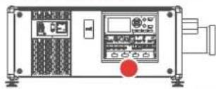
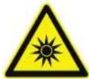
Hazard RG3: optical radiation warning symbol
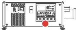
Hazard class 2: laser radiation warning symbol. 0.95 mW - 638 nm.
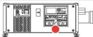
WARNING! DO NOT LOOK INTO THE BEAM NO DIRECT EYE EXPOSURE TO THE PROJECTOR BEAM IS PERMITTED LASER RADIATION - DO NOT STARE INTO LASER RANGING BEAM RG3 IEC EN 62471-5:2015 CLASS 2 IEC EN 60825-1:2014 HAZARD DISTANCE: CONSULT SAFETY MANUAL
THIS PRODUCT IS IN CONFORMITY WITH PERFORMANCE STANDARDS FOR LASER PRODUCTS UNDER 21 CFR 1040, EXCEPT WITH RESPECT TO THOSE CHARACTERISTICS AUTHORIZED BY VARIANCE NUMBER 2016-V-0144 EFFECTIVE ONDECEMBER 12, 201

THIS PRODUCT IS IN CONFORMITY WITH PERFORMANCE STANDARDS FOR LASER PRODUCTS UNDER 21 CFR 1040, EXCEPT WITH RESPECT TO THOSE CHARACTERISTICS AUTHORIZED BY VARIANCE NUMBER 2016-V-0144 EFFECTIVE ON JUNE 07, 2017.
1.5 High Brightness precautions: Hazard Distance

HD
Hazard Distance (HD) is the distance measured from the projection lens at which the intensity or the energy per surface unit becomes lower than the applicable exposure limit on the cornea or on the skin. The light beam is considered (to be) unsafe for exposure if the distance from a person to the light source is less than the HD.
Restriction Zone (RZ) based on the HD
The HD depends on the amount of lumens produced by the projector and the type of lens installed. See chapter "HD in function of modifying optics", page 20.
To protect untrained end users (as cinema visitors, spectators) the installation shall comply with the following installation requirements: Operators shall control access to the beam within the hazard distance or install the product at a height that will prevent spectators' eyes from being in the hazard distance. Radiation levels in excess of the limits will not be permitted at any point less than 2.0 meter (SH) above any surface upon which persons other than operators, performers, or employees are permitted to stand or less than 1.0 meter (SW) lateral separation from any place where such persons are permitted to be. In environments where unrestrained behavior is reasonably foreseeable, the minimum separation height should be greater than or equal to 3.0 meter to prevent potential exposure, for example by an individual sitting on another individual's shoulders, within the HD.
These values are minimum values and are based on the guidance provided in IEC 62471-5:2015 section 6.6.3.5.
The installer and user must understand the risk and apply protective measures based upon the hazard distance as indicated on the label and in the user information. Installation method, separation height, barriers, detection system or other applicable control measure shall prevent hazardous eye access to the radiation within the hazard distance.
For example, projectors that have a HD greater than 1 m and emit light into an uncontrolled area where persons may be present should be positioned in accordance with “the fixed projector installation” parameters, resulting in a HD that does not extend into the audience area unless the beam is at least 2.0 meter above the floor level. In environments where unrestrained behavior is reasonably foreseeable, the minimum separation height should be greater than or equal to 3.0 meter to prevent potential exposure, for example by an individual sitting on another individual's shoulders, within the HD. Sufficiently large separation height may be achieved by mounting the image projector on the ceiling or through the use of physical barriers.
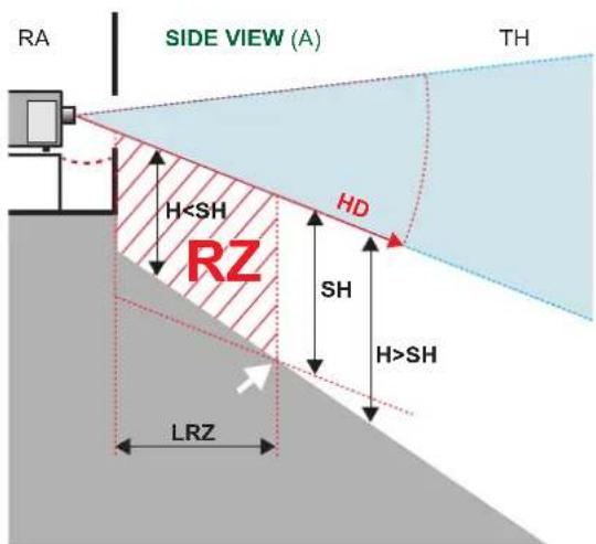
Image 1-2
A Side view
B Top view
RA Restricted Access location (boot area of projector).
TH Theater
RZ Restriction Zone in the theater
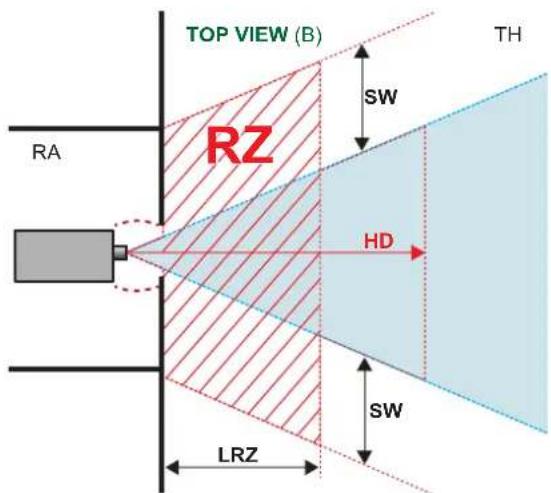
HD Hazard Distance
LRZ Length Restriction Zone in the theater
H Height between surface floor and the light beam
SH Separation Height
SW Separation Width
Based on national requirements, no person is allowed to enter the projected beam within the zone between the projection lens and the related hazard distance (HD). This shall be physically impossible by creating sufficient separation height or by placing barriers. The minimum separation height takes into account the surface upon which persons other than operator, performers or employees are permitted to stand.
On Image 1–3 a typical setup is displayed. It must be verified if these minimum requirements are met. If required a restricted zone (RZ) in the theater must be established. This can be done by using physical barrier, like a red rope as illustrated in Image 1–3.
The restricted area sticker can be replaced by a sticker with only the symbol.
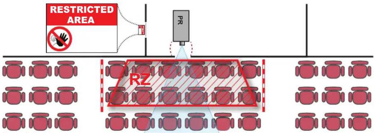
Image 1-3
USA market
For LIPs (Laser Illuminated Projectors) installed in the USA market other restriction zone conditions apply.
LIPs for installation in restrained environment (cinema theaters, business rooms, class rooms, museums ...) shall be installed at height vertically above the floor such that the bottom plane of the hazard distance zone shall be no lower than 2.5 meters above the floor. Horizontal clearance to the hazard distance zone shall be not less than 1 meter. Alternatively, in case the height of the separation barrier for the horizontal clearance is at least 1 meter high then the horizontal clearance (SW) can be reduced to:
- 0 meter if the height of the hazard zone is minimum 2.5 meter.
- 0.1 meter if the height of the hazard zone is minimum 2.4 meter.
- 0.6 meter if the height of the hazard zone is minimum 2.2 meter.
LIPs for installations in unrestrained environment (concerts, ...) shall be installed at a height vertically above the floor such that the bottom plane of the Hazard distance Zone shall be no lower than 3 meters above the floor. Horizontal clearance to the hazard distance zone shall be not less than 2.5 meters. Any human access horizontally to the Hazard Zone, if applicable, shall be restricted by barriers. If human access is possible in an unsupervised environment, the horizontal or vertical clearances shall be increased to prevent exposure to the hazard distance zone.
The LIP shall be installed by Barco or by a trained and Barco-authorized installer or shall only be transferred to laser light show variance holders. This is applicable for dealers and distributors since they may need to install the LIP (demo install) and/or they transfer (sell, rent, lease) the LIP. Dealers and distributors shall preserve sales and installation records for a period of 5 years. Variance holders may currently hold a variance for production of Class IIIB and IV laser light shows and/or for incorporating RG3 LIPs. Laser light show variance for RG3 LIPs can be requested by mailing the application to RadHealthCustomerService@fda.hhs.gov.
The installation checklist for laser illuminated RG3 projectors must be fully completed after the installation. The installation checklist can be downloaded from the Barco website. The installer shall preserve the checklist for a period of 5 years.
Install one or more readily accessible controls to immediately terminate LIP projection light. The power input at the projector side is considered as a reliable disconnect device. When required to switch off the projector, disconnect the power cord at the projector side. In case the power input at the projector side is not accessible (e.g. truss mount), the socket outlet supplying the projector shall be installed nearby the projector and be easily accessible, or a readily accessible general disconnect device shall be incorporated in the fixed wiring.
1.6 HD for fully enclosed projection systems

HD
Hazard Distance (HD) is the distance measured from the projection lens at which the intensity or the energy per surface unit becomes lower than the applicable exposure limit on the cornea or on the skin. The light beam is considered (to be) unsafe for exposure if the distance from a person to the light source is less than the HD.
Restriction Zone (RZ) based on the HD
The projector is also suitable for rear projection applications; projecting a beam onto a defuse coated projection screen. As displayed in Image 1–4 two areas should be considered: the restricted enclosed projection area (RA) and the observation area (TH).
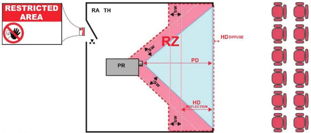
Image 1–4
RA Restricted Access location (enclosed projection area).
PR Projector.
TH Theater (observation area).
RZ Restriction Zone.
PD Projection Distance.
SW Separation Width. Must be minimum 1 meter.
For this type of setup 3 different HD shall be considered:
- HD as discussed in "High Brightness precautions: Hazard Distance", page 16, relevant for intrabeam exposure.
- HD_ reflection : the distance that has to be kept restrictive related to the reflected light from the rear projection screen.
- HD_ diffuse : the relevant distance to be considered while observing the diffuse surface of the rear projection screen.
As described in "High Brightness precautions: Hazard Distance", page 16, it is mandatory to create a restricted zone within the beam areas closer than any HD. In the enclosed projection area the combination of two restricted zones are relevant: The restricted zone of the projected beam toward the screen; taking into account 1 meter Separation Width (SW) from the beam onward. Combined with the restricted zone related to the rear reflection from the screen (HD), also taking into account a 1 meter lateral separation.
The HD _reflection distance equals 25% of the difference between the determined HD distance and the projection distance to the rear projection screen. To determine the HD distance for the used lens and projector model see chapter “HD in function of modifying optics”, page 20.
$$ \mathrm{HDreflection} = 25 \% (\mathrm{HD} - \mathrm{PD}) $$
The light emitted from the screen within the observation shall never exceed the RG2 exposure limit, determined at 10 cm. The HDuse can be neglected if the measured light at the screen surface is below 5000 cd/m² or 15000 LUX.
1.7 HD in function of modifying optics
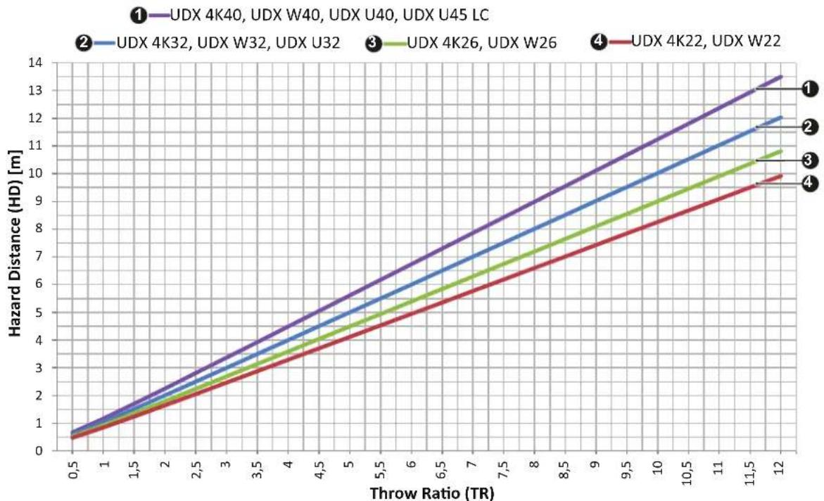
Hazard Distance
line
| Throw Ratio (TR) | UDX 4K40, UDX W40, UDX U40, UDX U45 LC | UDX 4K32, UDX W32, UDX U32 | UDX 4K26, UDX W26 | UDX 4K22, UDX W22 | | ---------------- | -------------------------------------- | -------------------------- | ----------------- | ----------------- | | 0.5 | 0.8 | 0.7 | 0.6 | 0.5 | | 1 | 1.6 | 1.5 | 1.4 | 1.3 | | 1.5 | 2.4 | 2.3 | 2.2 | 2.1 | | 2 | 3.2 | 3.1 | 3.0 | 2.9 | | 2.5 | 4.0 | 3.9 | 3.8 | 3.7 | | 3 | 4.8 | 4.7 | 4.6 | 4.5 | | 3.5 | 5.6 | 5.5 | 5.4 | 5.3 | | 4 | 6.4 | 6.3 | 6.2 | 6.1 | | 4.5 | 7.2 | 7.1 | 7.0 | 6.9 | | 5 | 8.0 | 7.9 | 7.8 | 7.7 | | 5.5 | 8.8 | 8.7 | 8.6 | 8.5 | | 6 | 9.6 | 9.5 | 9.4 | 9.3 | | 6.5 | 10.4 | 10.3 | 10.2 | 10.1 | | 7 | 11.2 | 11.1 | 11.0 | 10.9 | | 7.5 | 12.0 | 11.9 | 11.8 | 11.7 | | 8 | 12.8 | 12.7 | 12.6 | 12.5 | | 8.5 | 13.6 | 13.5 | 13.4 | 13.3 | | 9 | 14.4 | 14.3 | 14.2 | 14.1 | | 9.5 | 15.2 | 15.1 | 15.0 | 14.9 | | 10 | 16.0 | 15.9 | 15.8 | 15.7 | | 10.5 | 16.8 | 16.7 | 16.6 | 16.5 | | 11 | 17.6 | 17.5 | 17.4 | 17.3 | | 11.5 | 18.4 | 18.3 | 18.2 | 18.1 | | 12 | 19.2 | 19.1 | 19.0 | 18.9 |Image 1-5
HD Hazard Distance
TR Throw Ratio
1.8 Radio equipment (optional)
CE Conformity
This device may be equipped with WiFi & GSM modules for Pulse Input & Communication unit, which are fit for use in the European Union countries, EFTA and Turkey.
This device is restricted to indoor use only when operating in the 5150 to 5250 MHz frequency range.
Hereby, Barco declares that the radio equipment type UDX is in compliance with Directive 2014/53/EU. The full text of the EU declaration of conformity is available at the following internet address: https://www.barco.com/support
WiFi & GSM module
For WLAN:
• Frequency: 2402 MHz - 2482 Mhz
• Max EIRP: 19 dBm
• Frequency: 5150 - 5350 MHz / 5470 - 5725
• Max EIRP: 23 dBm
For GSM:
• E-GSM:
- Frequency: 900 MHz
Mhz - Max EIRP: 33.5 dBm
- EDGE:
- Frequency: 900 MHz
- Max EIRP: 28 dBm
- DCS:
- Frequency: 1800 MHz
- Max EIRP: 30.5 dBm
- EDGE:
- Frequency: 1800 MHz
- Max EIRP: 27 dBm
For UMTS:
- Band 1:
- Frequency: 2100 MHz
- Max EIRP: 24 dBm
- Band 8:
- Frequency: 900 MHz
- Max EIRP: 24 dBm
1.9 Compliance
UK Compliance

This product is fit for use in the UK.
Authorised Representative: Barco UK Ltd
Address: Building 329, Doncastle Road
Bracknell RG12 8PE, Berkshire, United Kingdom
1.10 Download Product Manual
Download Product Manual
Product manuals and documentation are available online at www.barco.com/td.
Registration may be required; follow the instructions given on the website.
IMPORTANT! Read Installation Instructions before connecting equipment to the mains power supply.
Getting started 2
2.1 Getting to know the projector 24
2.2 Power on projector....25
2.3 Start image projection 26
2.4 Switching to ready mode 29
2.5 Power off projector....29
About this chapter
This chapter and by extension this whole document, the user manual, is intended for the user who want's to operate the projector. It does not contain installation instructions because the installation has to be done by trained and qualified service technicians. Refer to the projector installation manual for detailed installation instructions.
2.1 Getting to know the projector
Orientation convention
This manual refers to the left side of the projector as the side at your left hand when standing behind the projector and looking at the projection screen in front of the projector.
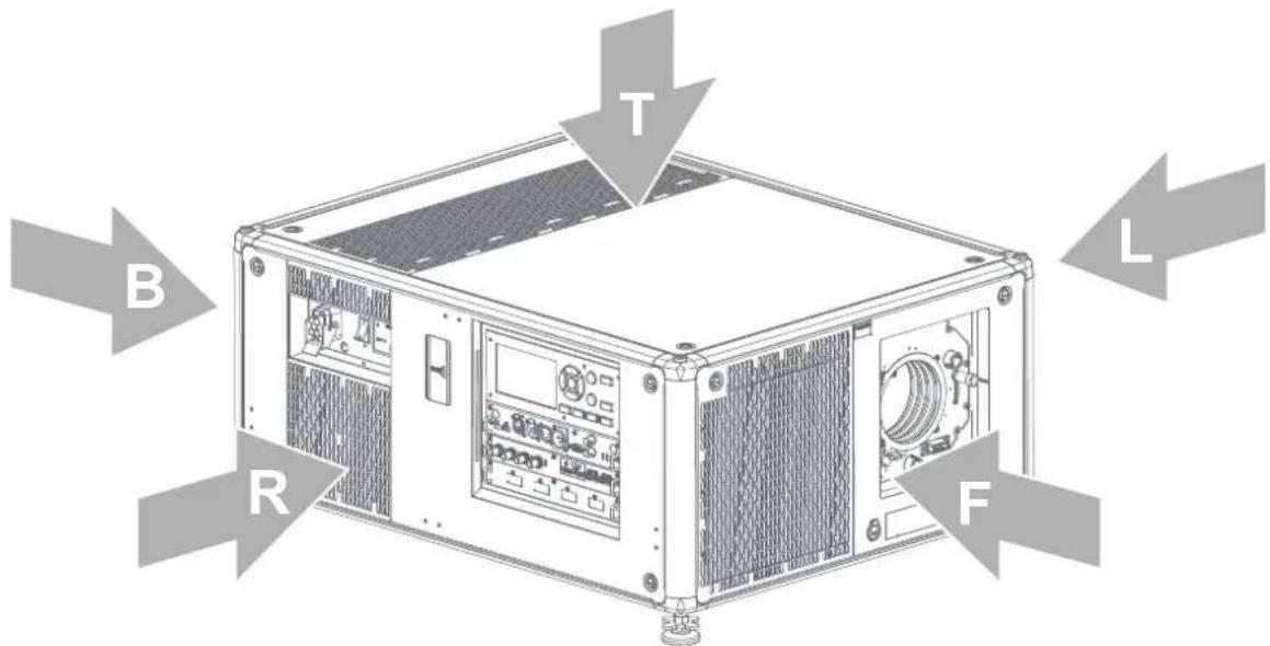
Image 2-1
T Top
L Left
F Front
R Right
B Back
Projector component location
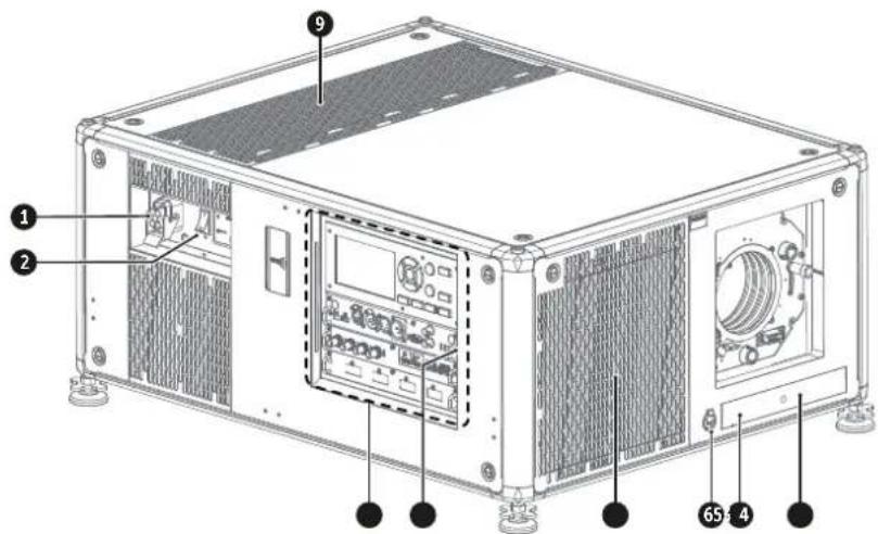
Image 2-2
1 Power input socket
2 Power On/Off switch
3 Input & Communication module
4 IR receiver projector right side
5 Dust filter front air inlet
6 Auxiliary connector (for external shutter, DMX, ...)
7 IR receiver projector front side
8 Distance meter (optional)
9 Dust filter top air inlet
For detailed info about the Input & Communication module see chapter "Input & Communication", page 39.
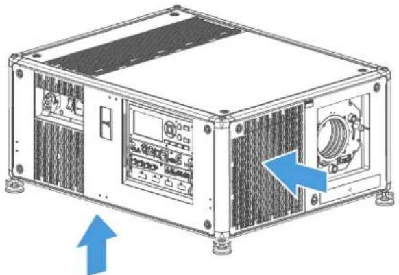
Projector airflow
The projector has 4 air inlet channels and 2 air outlets. The air outlets are located at the rear of the projector. The air inlets are located at the top, bottom and right side of the projector.
natural_image
Technical line drawing of a server rack unit with ventilation grilles and control panel (no text or symbols)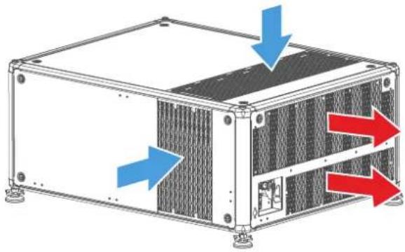
natural_image
Technical diagram of a modular electronic device with blue and red directional arrows indicating flow or movement (no text or symbols present)Image 2-3
Projector Infra Red receivers and Remote Control Unit
The projector has three Infra Red receivers: one at the rear (next to the power input), one at the front (below the lens holder) and one at the right side (integrated in the Input & Communication module).
Point the Remote Control Unit (RCU) directly to the Infra Red (IR) receiver. Make sure you are within the effective operating distance (30 m, 100 ft in a straight line)
The RCU will not function properly if strong light strikes the IR sensor window or if there are obstacles between the RCU and the IR sensor.
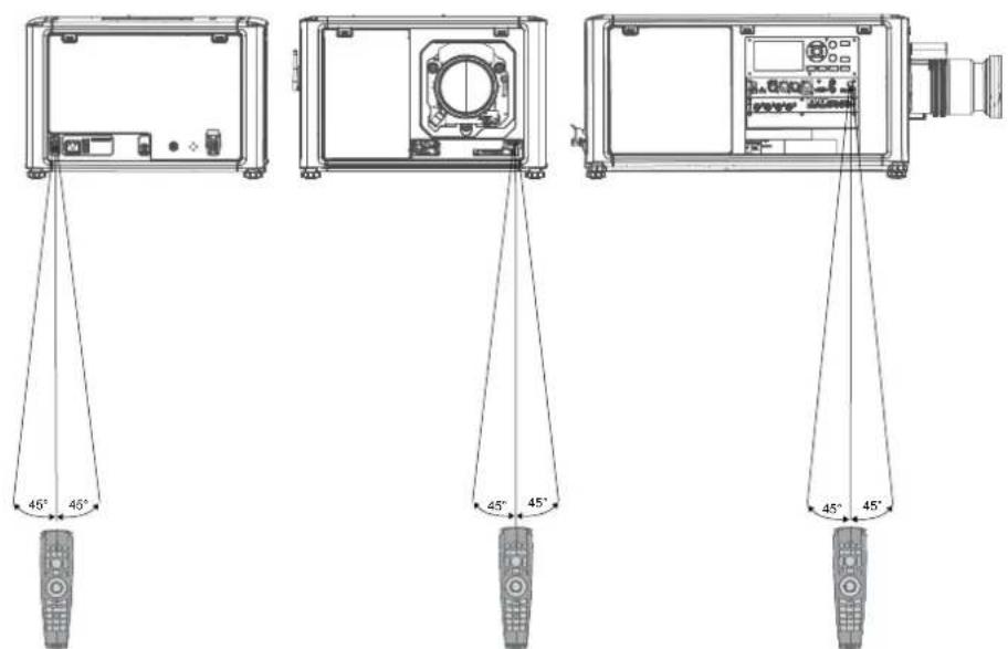
Image 2-4
For detailed info about the RCU see chapter "Pulse Remote Control Unit", page 31.
2.2 Power on projector
How to power on
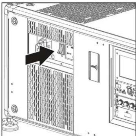
- Press the mains switch at the side of the projector to switch on this projector.
natural_image
Diagram of an internal server rack with ventilation grilles and a door, showing no text or symbolsImage 2-5 Mains switch
- When '0' is pressed, the projector is switched off.
- When 'I' is pressed, the projector is switched on.
The projector starts up to Ready mode. The Power on/off button will blink until Ready mode is achieved. Once in Ready mode, the Power on/off button will be lit WHITE.
The start up screen is displayed on the touch panel. Once the startup is completed, the status screen will be displayed.

- Press the Power on/off button on the projector, or the Power On button on the remote control.
The projector will continue to power on mode. The Power on/off button will blink until the projector is ready for projection. Once the projector is fully started up, the Power button will be lit BLUE.

The current mains input voltage is indicated on the voltmeter just above the power switch.

The background image of the startup screen and info screens can be changed with Projector Toolset with an installed UDX plug-in.
2.3 Start image projection
Connect the source
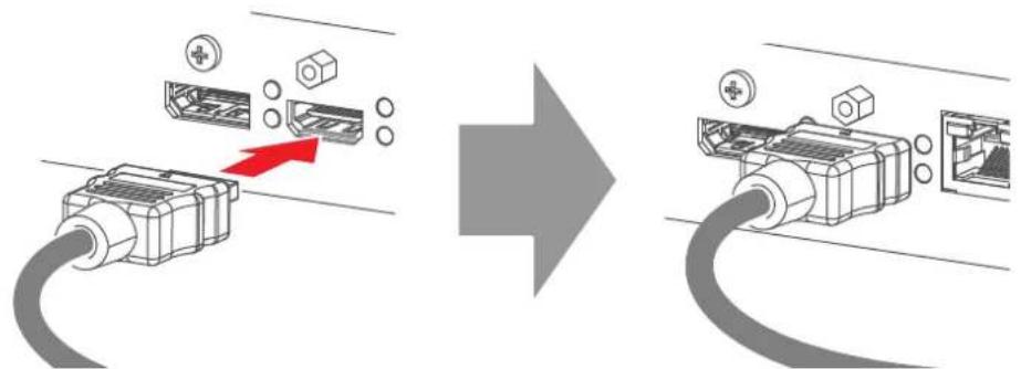
- Connect the source cable with the appropriate input port on the Input & Communication module.

Tip: See chapter "Input & Communication", page 39, for more info about supported input formats.
natural_image
Diagram showing a cable being inserted into an Ethernet device, with no text or symbols present.Image 2-8 Example of connecting an HDMI source.
- Check if the SYNC LED lit up ORANGE (reference 1). This indicates that the sync is detected on the input signal.
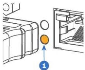
Image 2-9
Select the source
- Press the Input button (reference I) on the remote control or local keypad.
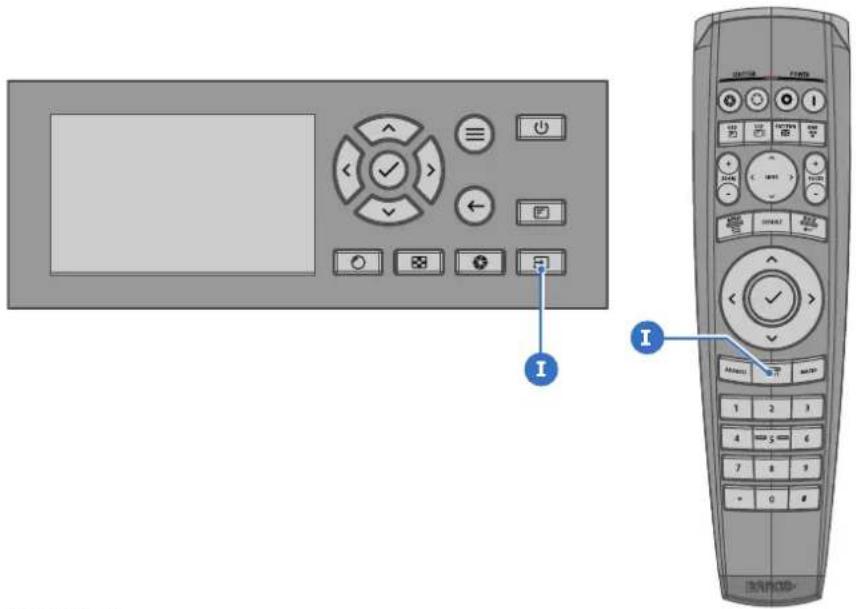
Image 2-10
The Source selection menu opens on the LCD display.
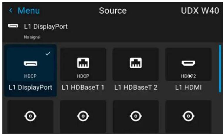
Image 2-11 Example of the input selection menu
-
Use the arrow keys to select the desired source.
-
the SEL LED (reference 2) of the selected source lit up GREEN, and
- the image of the selected source is projected.
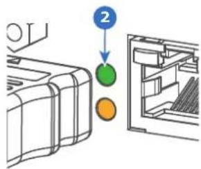
Image 2-12
Quick test pattern selection
- Press the Test pattern button (references P) on the remote control or local keypad.
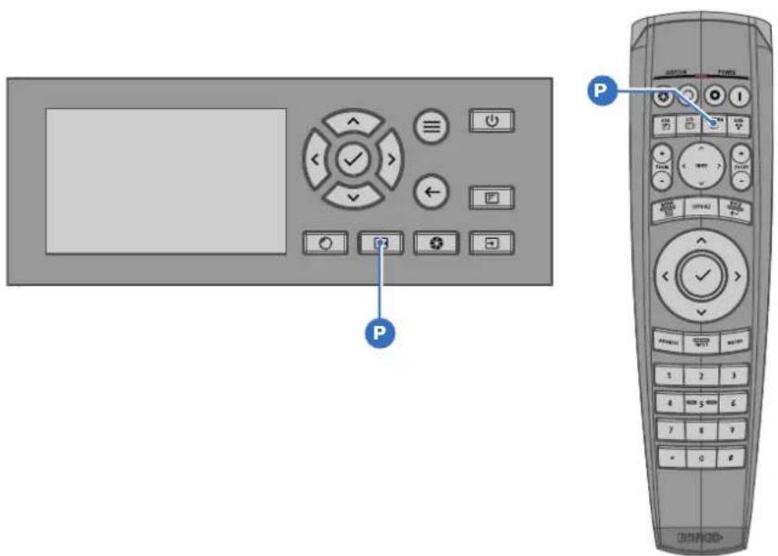
Image 2-13
The Test pattern menu opens on the LCD display.
- Use the arrow keys to select the desired test pattern.
2.4 Switching to ready mode
How to switch to ready mode
- Press and hold the Power on/off button for 3 seconds on the local keypad, or press the Power Off button on the remote control.
The projector goes to Ready mode. The after-cooling cycle will start (about 30 seconds). During this period the Power on/off button will blink. Once the after-cooling cycle has ended, the projector will be in ready mode and the Power on/off button will be lit WHITE.
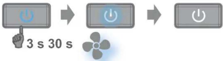
flowchart
graph LR
    A["3 s"] --> B["30 s"]
    B --> C["Power Supply Icon"]
Image 2-14

While in ready mode, you can still navigate through the menus and set a limited amount of parameters.
Depending on the power savings settings of your device, if left untouched the projector will eventually go into standby or eco mode.
2.5 Power off projector

CAUTION: This procedure assumes the projector is in standby or ready mode.
How to power off
- Switch off the projector with the mains switch. '0' must be pressed.
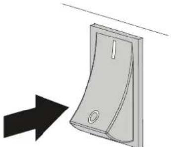
natural_image
Diagram of a door switch with a black arrow pointing to it (no text or symbols present)Image 2-15
- Unplug the power cord from the projector.
Pulse Remote Control Unit
3
3.1 Pulse RCU, battery installation 32
3.2 Pulse RCU, protocol setup 33
3.3 Pulse RCU, function of the on/off button 33
3.4 Using the RCU 34
3.5 Pulse RCU, Functionality overview 35
3.6 Pulse RCU, function of the "button pressed indicator" 35
3.7 Pulse RCU, function of the "RGB filter" button 36
3.8 Displaying and Programming addresses into the RCU 36
3.9 Using the XLR connector of the RCU 36
3.10 Using the mini-jack connector of the RCU 37
3.11 Pulse RCU, silicone protection sleeve (optional) 37
3.1 Pulse RCU, battery installation
Where to find the batteries for the remote control ?
The batteries are not placed in the remote control unit to avoid control operation in its package, resulting in a shorter battery life time. At delivery the batteries can be found in a separated bag attached to the remote control unit. Before using your remote control, install the batteries first.
How to install
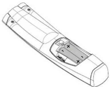
- Push the battery cover tab with the fingernail a little backwards (1) and pull, at the same time, the cover upwards (2).
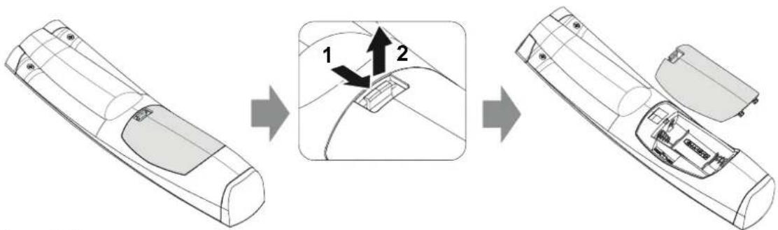
Image 3-1
- Insert the two AA size batteries, making sure the polarities match the + and - marks inside the battery compartment.

Tip: Use alkaline batteries for optimum range and life time.
natural_image
Line drawing of a remote control casing with visible internal compartments and mounting points (no text or symbols)Image 3-2
- Insert (1) both lower tabs of the battery cover in the gaps at the bottom of the remote control, and press (2) the cover until it clicks in place.
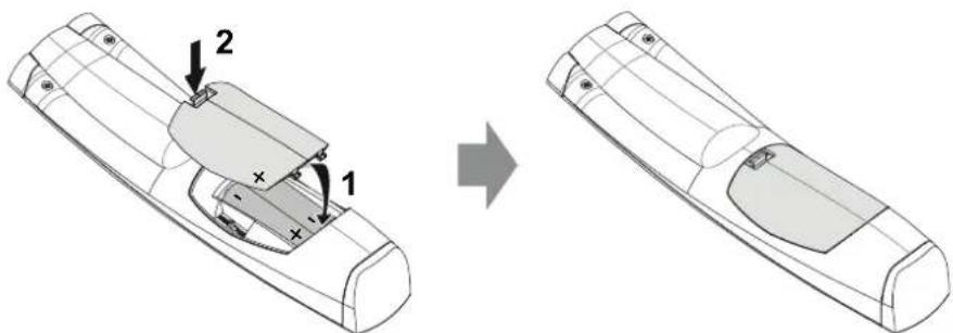
Image 3-3

When replacing batteries, the broadcast address of the RCU will be reset to its default value '0'.

CAUTION: Replace with the correct battery type. Use two AA size batteries. There is a risk of explosion if the battery is replaced with an incorrect type.

CAUTION: Replace the battery as explained above. There is a risk of explosion if the battery is incorrectly installed.
3.2 Pulse RCU, protocol setup
About the used protocol
The protocol is the code send out by the remote control when a button is pressed. Depending on this code, the projector can decode the signals. The remote control can be used with two different protocols: RC5 and NEC. Depending on the projector to control the remote control can be switched between these protocols.
Which protocol to use
- The NEC protocol has to be used for Barco projectors based on the Pulse platform: F70, F80, F90, HDX 4K, UDX, UDM, XDL, etc.
• The RC5 protocol has to be used all legacy Barco projectors: HDQ 2k40, HDF, HDX W, etc.
How to set
- Remove the cover. For more info on how to remove, see "Pulse RCU, battery installation", page 32.
- Place the switch in the desired position.
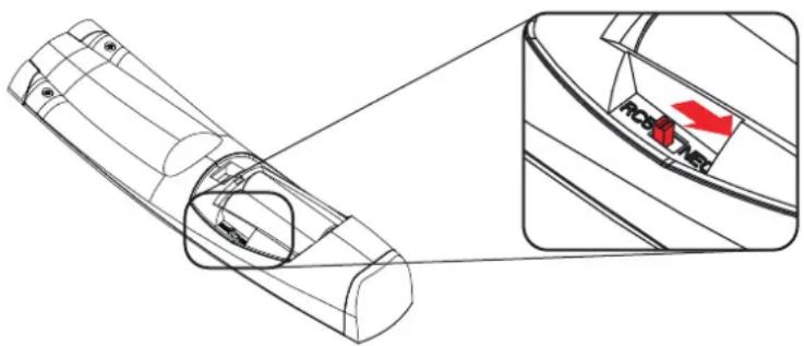
Image 3-4
Remarks when using the RC5 protocol
Due to new or updated functionality not all buttons of the Pulse RCU are one-to-one compatible with the legacy Barco RCU and projectors. Take the following limitations into account:
- Buttons Shutter open and Shutter close emit the same code when in RC5 mode. This because the legacy RCU's only had 1 button for Shutter functionality.
- Buttons Power on and Power off emit the same code when in RC5 mode. This because the legacy RCU's only had 1 button for Power functionality.
- The RGB filter button is not supported.
- The Input selection button is not supported.
- The Default value button is not supported.
- The Macro button is not supported.
3.3 Pulse RCU, function of the on/off button
Function of the remote control on/off button
The Pulse remote control unit has at the front side an on/off switch (reference 1 Image 3–5). Switching off the remote control prevents that unwanted commands are send due to an accidental key press. Furthermore, switching the RCU off will extend the battery life time of the remote control.
To activate the remote control, press the on/off button.
To deactivate the remote control, press the on/off button again.
Default after (re)placing batteries, is "ON".
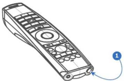
natural_image
Line drawing of a remote control device with labeled connection point (no text or symbols on the device itself)Image 3-5
3.4 Using the RCU
Pointing to the reflective screen or IR sensors
Switch on the RCU and point the front of the RCU to the reflective screen surface or point directly to one of the projector IR sensors. Make sure you are within the effective operating distance (30 m, 100 ft in a straight line). The RCU will not function properly if strong light strikes the IR sensor window or if there are obstacles between the RCU and the IR receiver.
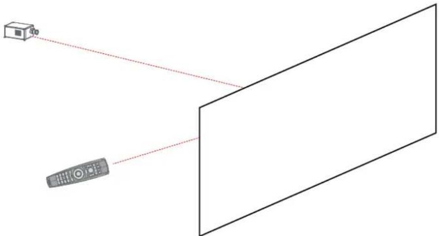
natural_image
Diagram showing a remote connected to a rectangular screen, with a small box nearby (no text or symbols)Image 3-6
The RCU can also hard-wired been used. See chapter "Using the XLR connector of the RCU", page 36.
Using the RCU in combination with a 3D emitter
When using a 3D emitter that radiates IR beams (e.g. the optional 3D emitter that Barco provides), the IR beams of the 3D emitter may interfere with the IR communication between projector and the RCU.
If such interference occurs, connect the RCU to the projector using the remote cable with XLR connector. It is also be advised to turn the IR receivers of the projector off to avoid the 3D emitter interference. The IR receivers can be turned off in the GUI: System Settings > Communication > IR Control.
3.5 Pulse RCU, Functionality overview
Remote Control Unit buttons
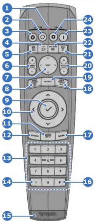
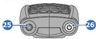
Image 3-7
1 Button pressed indicator
2 Shutter open
3 Shutter close
4 LCD panel on / off
5 Project OSD on / off
6 Lens zoom
7 Lens shift
8 Menu open / close
9 Menu selection, OK button
10 Menu navigation
11 Input selection
12 Address button
13 Numeric buttons
14 Backspace (while entering values)
15 XLR connector
16 Decimal mark (while entering values)
17 Macro button
18 Menu back
19 Default value button
20 Lens focus
21 RGB filter
22 Test patterns
23 Power on
24 Power off
25 3.5 mm jack
26 RCU on / off
3.6 Pulse RCU, function of the “button pressed indicator”
Functions button pressed indicator
- Rapidly flashes when commands are sent, this is the normal "button pressed" indication.
- 1 Short flash when remote control is switched ON by means of the on/off button.
- Continuously lit (up to 5 seconds) when address digits are expected after pressing the ADDR button.
- Slowly flashes (2 times a second) when the battery level is becoming low; typically when more than 85% of the useful life is past.
3.7 Pulse RCU, function of the "RGB filter" button
Filtering the color of the projected image
By pressing the RGB filter button on the RCU you can place a color filter on the output of the projector. This feature can be useful during the installation and configuration of a multi-projector or multi-channel setup. By having one projector project a red image and another project a green image, it is easier to spot and adjust the overlap section.
By pressing this button multiple times, you will have different active filters, in the following cycle:
• Red + Green + Blue (default)
- Red only
- Green only
- Blue only
- Red + Green
- Green + Blue
- Red + Blue
- Red + Green + Blue
- etc

After powering up, the colors will always revert back to full RGB.
3.8 Displaying and Programming addresses into the RCU
Displaying the Projector Address on the Screen.
- If the projector is on, press the menu key and navigate to the Status page. The projector address and the broadcast address can be seen under the Communication heading.
The projector's address is displayed on the LCD status screen and / or the OSD.
How to Program an Address into the RCU?
- Press the Address button until the Button pressed indicator lights up continuously (proximately 5 seconds).
- Enter the address with the digit buttons within the time the indicator lights up (also proximately 5 seconds).

Note: That address can be any value between 0 and 31.

Tip: A few examples:
To enter address 3, press "3" digit button on the RCU to set the RCU's address to 3 and wait until the button pressed indicator is out. Alternatively, you can also press "0" and "3". This way, the button pressed indicator goes out immediately.
To enter address 31, then press "3" and "1" on the digit button on the RCU and the button pressed indicator goes out immediately.
3.9 Using the XLR connector of the RCU

Connecting a cable with the XLR connector will reset the broadcast address of the RCU to its default value '0'.
How to use the XLR connector
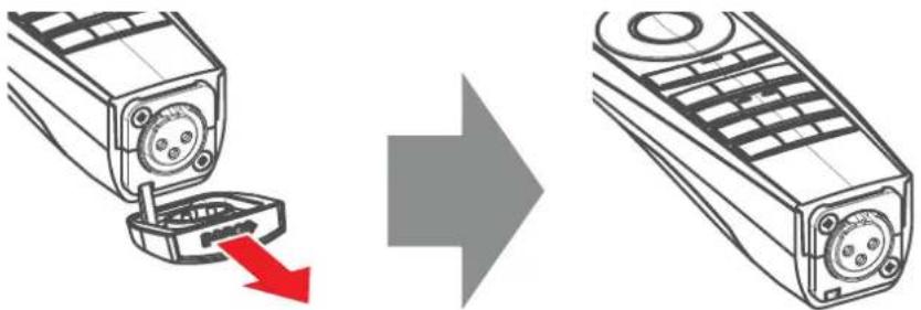
- Remove the XLR cover by pulling it backwards.
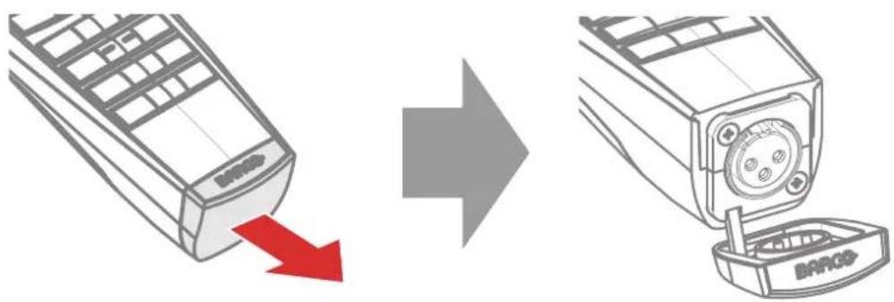
Image 3-8
-
Connect a cable with XLR plug into the XLR connector of the RCU.
-
Connect the other end of the cable with the XLR input of the projector.

Note: While the XLR cable is connected, the IR beam of the RCU is switched off.
3.10 Using the mini-jack connector of the RCU

Connecting a cable with the mini-jack connector will reset the broadcast address of the RCU to its default value '0'.
How to use the mini-jack connector
-
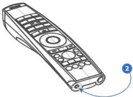
Connect a cable with the mini-jack connector (reference 2 Image 3-9) of the RCU.
-
Connect the other end of the cable with the mini-jack input of the projector.
natural_image
Line drawing of a remote control with labeled button (no text or symbols on device)Image 3-9

Note: While the mini-jack cable is connected, the IR beam of the RCU is switched off.
3.11 Pulse RCU, silicone protection sleeve (optional)
Introduction
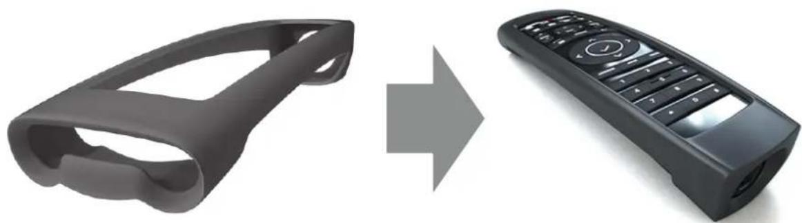
Barco offers a silicone form fitting protection sleeve for the Pulse RCU. The silicone material keeps it comfortably, non slip and soft touch. All buttons and holes remain accessible. The sleeve is quick and easy installed. For ordering information see Barco website.
How to install
- Pull off the rubber XLR-lid from the RCU.
natural_image
Diagram showing a mobile phone with a red arrow indicating a drop, followed by an arrow pointing to the right side of the phone (no text or symbols present)Image 3-10
- Place back side (XLR side) of the RCU into the sleeve and pull the other side of the sleeve over the front side of the RCU.
natural_image
Two black remote control devices, one with a handle and the other with a keypad, shown in transformation from left to right (no text or symbols)Image 3-11
Input & Communication
4
4.1 Introduction....40
4.2 Local Keypad and LCD panel 40
4.3 LCD touch panel....41
4.4 Communication connections....42
4.5 LED and Button indication chart....44
4.6 Pulse Quad Combo input Mk II 45
4.7 Pulse Quad Combo input Mk I 46
4.8 Pulse Quad DP 1.2 input....47
4.9 Pulse SFP input....48
4.1 Introduction
General
The Input & Communication module consists of a local keypad with LCD panel (1), a communication panel (4) and a Quad Combo input board (5). The free input slot can be used for optional modules (e.g. the Quad DP 1.2 input board).

Two boards of the same type can be used without restrictions. You can mount a second Quad Combo Input board in the free input slot (6). Alternatively, you can also remove the pre-mounted Quad Combo Input board and replace it with a second optional module (for example, a second Quad DP 1.2 input board).
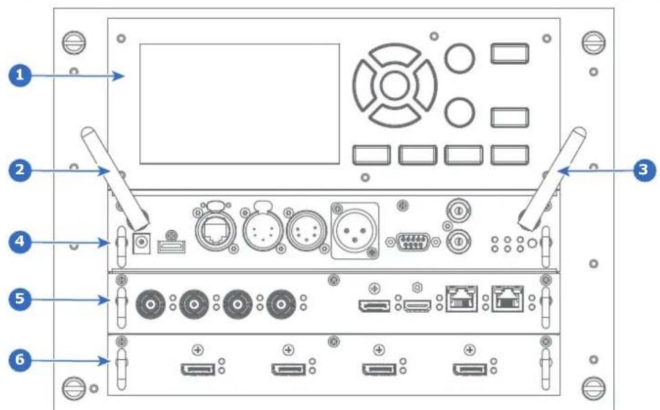
Image 4-1
1 Local Keypad and LCD panel
2 Optional antenna for WiFi connection
3 Optional antenna for GSM
4 Communication Panel
5 Quad Combo Input board
6 Free input slot (here filled with the Quad DP 1.2 Input board)
4.2 Local Keypad and LCD panel
Overview
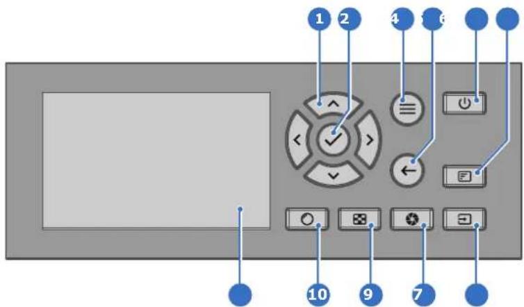
Image 4-2
1 Menu navigation
2 Menu confirmation, OK button
3 Menu open / close
4 Menu back
5 Power on / off
6 Project OSD on / off
7 Input selection
8 Shutter open / close
9 Test patterns
10 Lens adjustment
11 LCD panel
Local Keypad
The Keypad gives direct access to several functions, in addition to access to the menu system.
The keypad has a backlight that can be switched on and off manually. By default the light turns off after 5 minutes.
The Power button and Shutter buttons are equipped with white, blue and red backlit LEDs. The other keys are only equipped with white and blue backlit LEDs. The LEDs are controlled according to the features available.
LCD panel
The LCD panel has two main functions:
- Showing the menus, the adjustment information and also a mirror of the OSD, (On Screen Display) described in User Interface when this is enabled.
-
Information regarding the status of the projector showing this data:
-
Projector status
- Network address
- Active source
- Current firmware version
- Operation Data
• Active functions (Enabled Functions).
Toggle between the two indications by using the Menu button on the keypad, or on the remote control.
The LCD Display will fade out 30 seconds after the last key operation.
4.3 LCD touch panel

The LCD menus can occasionally be slightly different in layout compared with the OSD menu, due to a more optimal layout regarding to the touch functionality of the LCD.
LCD touch panel functionality
In addition to the remote control and the keypad, it is also possible to navigate in the menus with the touch functionality in the LCD panel.
Press the icons to select the functions.
Select switches to toggle.
Select and drag sliders to adjust slider value.
4.4 Communication connections
Communication Panel
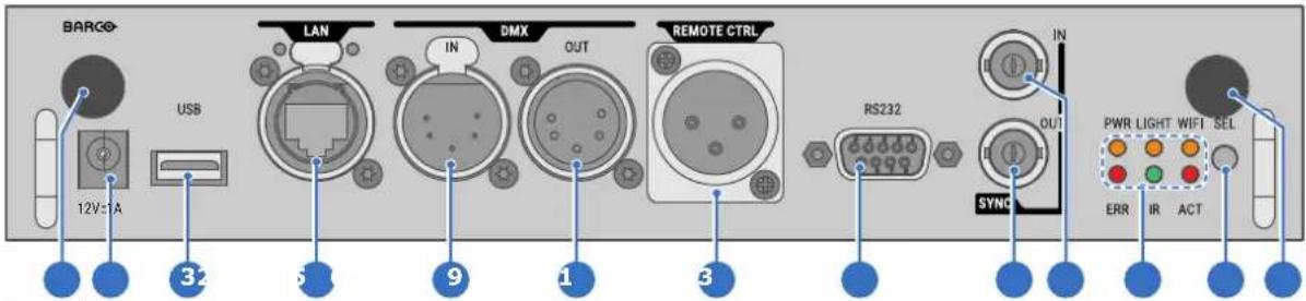
Image 4-3
1 WIFI antenna for wireless IP (optional)
2 12V 1A output
3 Firmware update / USB download log files
4 10/100 base-T for external control over IP and Art-Net
5 DMX interface input
6 DMX interface output
7 XLR input for wired projector control
8 RS232 for serial communication
9 Sync Out 3D
10 Sync In 3D
11 Status lights
12 IR receive sensor
13 GSM antenna input (optional)

CAUTION: Ethernet should only be connected to either the 10/100 base-T port (on the communication panel) or the HDBaseT input (on the Quad Combo Input Mk II). Using both same time will lead to undefined behavior.
at the
12 V output
12 V output, maximum 1 A, available when projector is not in stand by.
DMX interface
DMX is used as communication bus between different devices in the light technic. Each device has an input and an output, so that the bus can be looped between the different devices. According to the standard a five wire cable with XLR connector is used.
You can use the DMX input port to connect a DMX device (DMX console) to the projector. This way you can control the projector from that DMX device (console). The DMX output port can be connected with the next device in the loop.
DMX
| Pin | Description |
| 1 | Earth |
| 2 | Cold |
| 3 | Hot |
| 4 | Return - (or not used) |
| 5 | Return + (or not used) |

DMX
DMX-512 Lighting protocol over RS-485 interface. Carries information of 512 channels from a lighting controller to lighting devices. Standardized by USITT.
RS232/RS422 input
The communication interface of the UDX series projector supports RS232 and RS422 serial communication on two different types of input connectors, a Sub-D connector and an USB connector acting as RS input when connected to an USB input of a PC.
You can use the RS232/RS422 input to connect a local PC to your UDX series projector. By this way you can configure and control your projector from your local PC.
Advantages of using RS232/RS422 serial communication:
- easy adjustment of the projector via PC (or MAC).
- allow storage of multiple projector configurations and set ups.
- wide range of control possibilities.
- address range from 0 to 255.
- sending data to the projector (update).
- copying data from the projector (backup).
RS232/422 input (Sub-D) port
| Pin | Description |
| 1 | DCD : Data Carrier Detect |
| 2 | RXD- : Receive Data |
| 3 | TXD- : Transmitted Data |
| 4 | DTR : Data Terminal Ready [RS232] / TXD+ : Transmitted Data [RS422] |
| 5 | GND : Ground |
| 6 | DSR : Data Set Ready [RS232] / RXD+ : Received Data [RS422] |
| 7 | — (not connected) — |
| 8 | CTS : Clear To Send |
9 RI : Ring Indicator
RS232

An Electronic Industries Association (EIA) serial digital interface standard specifying the characteristics of the communication path between two devices using either D-SUB 9 pins or D-SUB 25 pins connectors. This standard is used for relatively short-range communications and does not specify balanced control lines. RS-232 is a serial control standard with a set number of conductors, data rate, word length and type of connector to be used. The standard specifies component connection standards with regard to computer interface. It is also called RS-232-C, which is the third version of the RS-232 standard, and is functionally identical to the CCITT V.24 standard. Logical '0' is > + 3V, Logical '1' is < - 3V. The range between -3V and +3V is the transition zone.
RS422

An EIA serial digital interface standard that specifies the electrical characteristics of balanced (differential) voltage, digital interface circuits. This standard is usable over longer distances than RS-232. This signal governs the asynchronous transmission of computer data at speeds of up to 920,000 bits per second. It is also used as the serial port standard for Macintosh computers. When the difference between the 2 lines is < - 0.2V that equals with a logical '0'. When the difference is > +0.2V that equals to a logical '1'.
USB port
The communication interface is equipped with a master USB port, type "A" connector. This USB port will simplify the service procedures for firmware updates or for downloading the log files without a network connection.
If the only file on the USB device is the firmware file (a “*.fw” file), the projector will automatically start one of the following processes.
- cornet
.fw: The projector will upgrade or downgrade, depending on the version number. - LogExtractor.fw: The log files will be downloaded.

Make sure that any used USB-stick is FAT32 compatible and contains no other files or folders.
4.5 LED and Button indication chart
Button Backlight Status
| Button Color status | Description | |
Power button | Blinking WHITE (slow) Projector starts up (booting) | |
| Blinking WHITE (fast) Firmware upgrade | ||
| Solid WHITE Projector is in Standby or Ready mode | ||
| Blinking BLUE Projector goes to ON mode | ||
| Solid BLUE Projector is ON | ||
| Blinking RED Error condition | ||
Shutter button | Off (no color) Projector is OFF, starts up, or is in Standby or Ready mode. | |
| Solid WHITE Projector is ON, shutter is open | ||
| Solid RED Projector is ON, shutter is closed | ||
LED Status
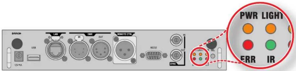
| LED | Color status | Description |
| PWR (power LED) | Off | Projector powers up |
| RED | Projector is in Standby mode | |
| ORANGE | Projector is in Ready mode | |
| GREEN | Projector is on | |
| LIGHT (Illumination LED) | Off | Light source is off |
| RED | No light source detected | |
| ORANGE | Light source is on in ECO mode | |
| GREEN | Light source is on in normal mode | |
| GREEN-ORANGE | Light source is on in CLO mode | |
| ERR (error LED) | Off | No error |
| RED toggles on/off | Error | |
| ORANGE toggles on/off | Warning | |
| IR | RED | IR signal received |
| GREEN | IR signal acknowledged |
4.6 Pulse Quad Combo input Mk II
Overview Quad Combo Input Mk II

Image 4-4
1 Quad SDI channel A: 3G/12G input
2 Quad SDI channel B: 3G input
3 Quad SDI channel C: 3G SDI input + 3G/12G output
4 Quad SDI channel D: 3G SDI input / output
5 DisplayPort Input
6 HDMI input
7 HDBaseT input 1
8 HDBaseT input 2
Functionality of the Quad Combo input Mk II
The Quad Combo Input Mk II support 12G input and throughput on the SDI connectors.
Compared with the Mk I the Mk II includes the following:
• SDI input A supports 12G input signals.
• SDI input C functions as a loop-through output for any signal placed on input A.
• SDI input D functions as a loop-through output for any signal placed on input B.
- HDBaseT input 1 supports network connectivity.

CAUTION: Ethernet should only be connected to either the 10/100 base-T port (on the communication panel) or the HDBaseT input (on the Quad Combo Input Mk II). Using both at the same time will lead to undefined behavior.
SDI input & output - How does it work?
When connecting an SDI source to the projector and the signal is HD or 3G, you can choose any of the four input connectors.
When connecting multiple projectors with the same signal, you can connect the signal as follows:
- Connect the source signal to Input A or B of the first projector.
• If the source signal is connected to input A, connect input/output C to the Input of the following projector.
• If the source signal is connected to input B, connect input/output D to the Input of the following projector. - Continue in the same fashion until all projectors are connected.
When connecting a 12G SDI source to the projector, you can only connect that source to input A.

Only Input A accepts 12G SDI signals. While it is technically possible to connect a 12G SDI source to Input B and connect that source to another projector in line (using Input/Output D), this first projector itself will not be able to process the 12G signal.
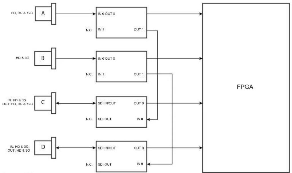
flowchart
graph LR
    A["HD, 3G & 12G"] --> IN0OUT0["IN 0 OUT 0"]
    IN0OUT0 --> FPGA["FPGA"]
    B["HD & 3G"] --> IN0OUT0["IN 0 OUT 0"]
    IN0OUT0 --> FPGA
    C["IN: HD & 3G OUT: HD, 3G & 12G"] --> SDIINOUT["SDI IN/OUT OUT 0"]
    SDIINOUT --> FPGA
    D["IN: HD & 3G OUT: HD & 3G"] --> SDIINOUT["SDI IN/OUT OUT 0"]
    SDIINOUT --> FPGA
    IN0OUT0 --> N.C.
    IN1OUT1 --> N.C.
    SDIINOUT --> N.C.
    SDIOUT --> N.C.
    N.C. --> FPGA
    N.C. --> FPGA
    N.C. --> FPGA
    N.C. --> FPGA
    N.C. --> FPGA
    N.C. --> FPGA
    N.C. --> FPGA
Image 4-5
LED behavior
- The SYNC LED lit up ORANGE when valid input sync is detected.
- The SEL LED lit up GREEN when the input is selected.
- The SEL LED blinks GREEN when the input/output is selected and configured as output.

For specifications about the supported inputs for SDI, HDMI, HDBaseT and DisplayPort 1.2 see chapter "Specifications", page 175.
4.7 Pulse Quad Combo input Mk I
Overview Quad Combo input Mk I

Image 4-6
1 Quad SDI channel A: 3G input
2 Quad SDI channel B: 3G input
3 Quad SDI channel C: 3G input
4 Quad SDI channel D: 3G input
5 DisplayPort Input
6 HDMI input
7 HDBaseT input 1
8 HDBaseT input 2
LED behavior
- The SYNC LED lit up ORANGE when valid input sync is detected.
- The SEL LED lit up GREEN when the input is selected.

For specifications about the supported inputs for SDI, HDMI, HDBaseT and DisplayPort 1.2 see chapter "Specifications", page 175.
Remark concerning the Mk I and Mk II inputs boards
The Mk I input board miss functionality that has been implemented on the Mk II input board. These missing features include:
- Loop-through functionality
• 12G SDI support
• Network connectivity on HDBaseT inputs
The projector is now standard equipped with the Mk II input board. For details and specifications see chapter "Pulse Quad Combo input Mk II", page 45.
Visual difference between the Mk I and Mk II input boards
There is one real visual aid to tell the two variants apart. There are visual markings added on the Mk II input board, marking which connector supports 12G and which only supports 3G.
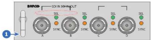
Image 4-7 Quad Combo Input Mk I board, without markings above the SDI inputs
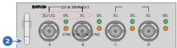
Image 4-8 Quad Combo Input Mk II board, with 3G/12G markings above the SDI inputs/outputs.
4.8 Pulse Quad DP 1.2 input
Quad DP 1.2 input

Image 4-9
1 Quad DisplayPort channel A input
2 Quad DisplayPort channel B input
3 Quad DisplayPort channel C input
4 Quad DisplayPort channel D input
LED behavior
- The SYNC LED lit up ORANGE when valid input sync is detected.
- The SEL LED lit up GREEN when the input is selected.

For specifications about the supported inputs for DisplayPort 1.2 see chapter "Specifications", page 175.
4.9 Pulse SFP input

The Barco SFP Input Board has been designed and tested to work alongside the Barco SFP Output Board.
However, it is possible that the SFP Input board can also work with other third-party devices that support 12G over fiber. Due to the many third-party options available on the market, the input board could not be tested for every option available.
Overview SFP input
The SFP Input board is used to connect 12G SDI over fiber. The SFP input is delivered without any connector. It is up to the customer to buy the necessary connectors, transceivers and cables. These parts can be mounted on the indicated places on the front panel of the board.

Image 4-10
1 Neutrik Duo optical connector or Neutrik Quad optical connector
2 Neutrik Duo optical connector or Neutrik Quad optical connector
3 2x12G SDI/10GE transceiver

For specifications about the supported inputs for SFP see chapter "Specifications", page 175.
LED behavior
- The SYNC LED lit up ORANGE when valid input sync is detected.
- The SEL LED lit up GREEN when the input is selected.
Use cases
The SFP can be configured as follows:
- SFP+ transceiver + Fiber connection (integrated or separated)
- Neutrik OpticalCon Duo + SFP+ transceiver + internal fiber
- Neutrik OpticalCon Quad + SFP+ transceiver + internal fiber
- Loop-through mode

See projector installation manual for detailed instructions on how to install/configure the SFP input.

WARNING: Only by Barco trained and qualified technicians are allowed to install the SFP input.

Optical Trancever to comply with Laser Class 1, IEC60825-1: 2014
GUI - Introduction
5
5.1 Overview 50
5.2 Navigation....53
5.3 Test Patterns....55
About this chapter
This chapter gives an general overview of the Graphic User Interface.
5.1 Overview
Disclaimer on GUI images used in this manual
The GUI images in this manual are example illustrations and should be treated as such. While the name of the projector displayed in the illustrations may be different from the projector model you are currently using, the menu lay-out and functionality is identical.
GUI - First start of the software
When you start the projector for the first time, you will be requested to choose the system language. You can choose between the following languages:
- German (DE)
- English (EN-US)
- Spanish (ES)
- French (FR)
- Japanese (JA)
- Korean (KO)
- Portuguese (PT-BR)
- Russian (RU)
- Chinese (ZH)
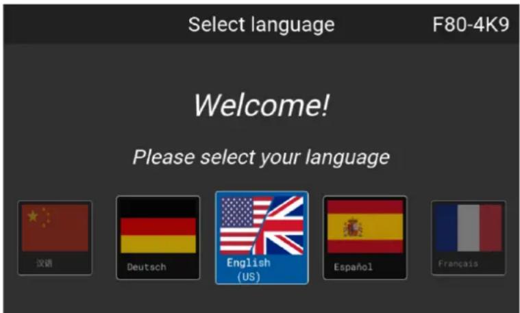
Image 5-1 Example of the welcome screen
Once you confirmed your choice, you will be prompted with the Pulse product-specific End User License Agreement (EULA). You will only be able to access the projector software once you have fully read and approved the EULA.
GUI - Product Registration
Upon first startup you will be requested to register the projector. You can perform the registration procedure now, or choose to Register Later. For more information on the entire registration procedure, refer to the Projector Registration user guide.
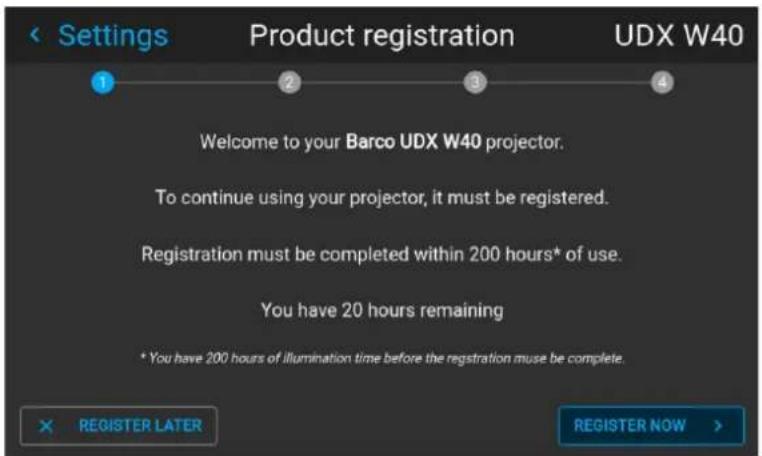
Image 5-2 Example of the Product registration form
GUI - Status Screens
While the projector menu is not active, or the projector is Ready or Standby mode, the Status screens remain visible. These screens give an overview of the state of the projector and can be navigated through using the left and right arrow keys, or by swiping the screen left or right. The status screens are the following:
- Dashboard: The main overview. This screen displays all the chosen options on the projector (chosen source, blending/masking, display mode, etc).
- About: General info about the projector. This includes serial number, software version, mounted lens and light source runtime. It also includes altitude, and the pitch and roll tilt angles.
- Notifications: The error and/or warning messages that are currently active. If no messages are active, this list will be empty.
- Preview: A preview pane of the projected image. If no image is being projected, a test image is displayed instead.
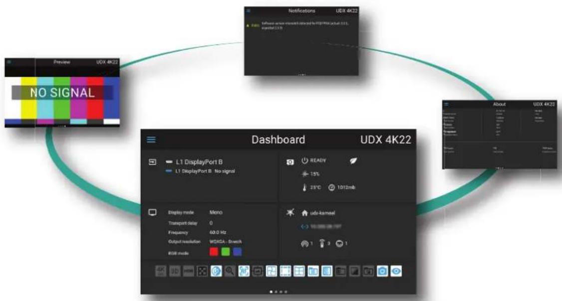
flowchart
graph TD
    A["Preview UDX 4K22"] --> B["NO SIGNAL"]
    B --> C["Dashboard UDX 4K22"]
    C --> D["L1 DisplayPort B No signal"]
    C --> E["READY 15% 25°C 1012mb"]
    C --> F["udr-kancel 1 3 1"]
Image 5-3 Example of a Dashboard status screen
GUI - Main Menu overview
The projector on-screen display (OSD) is the primary user interface (UI). From here, you can review and adjust all projector and display settings.
The OSD interface uses buttons to display the main menu. Each main menu contains submenus.
The OSD can be disabled by pressing the OSD on/off button.
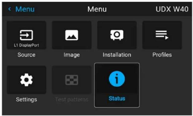
Image 5-4 Example of the home menu
The projector software platform uses access levels what each user can do. A standard user has access to the standard projector functionality. A certified service technician has also access to the advanced settings menu. This menu is password protected. This password can only be obtained by following the service partner training.
GUI - Pulse software menu tree
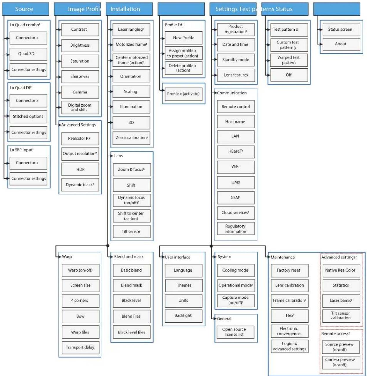
flowchart
graph TD
    A["Source"] --> B["Lx Quad combo¹"]
    B --> C["Connector x"]
    B --> D["Quad SDI"]
    B --> E["Connector settings"]
    A --> F["Lx Quad DP¹"]
    F --> G["Connector x"]
    F --> H["Stitched options"]
    F --> I["Connector settings"]
    A --> J["Lx SFP Input¹"]
    J --> K["Connector x"]
    J --> L["Connector settings"]
    A --> M["Image Profile"]
    M --> N["Contrast"]
    M --> O["Brightness"]
    M --> P["Saturation"]
    M --> Q["Sharpness"]
    M --> R["Gamma"]
    M --> S["Digital zoom and shift"]
    M --> T["Advanced Settings"]
    T --> U["Realcolor P7"]
    T --> V["Output resolution²"]
    T --> W["HOR"]
    T --> X["Dynamic black³"]
    A --> Y["Installation"]
    Y --> Z["Laser ranging¹"]
    Y --> AA["Motorized frame¹"]
    Y --> AB["Center motorized frame (action)¹"]
    Y --> AC["Orientation"]
    Y --> AD["Scaling"]
    Y --> AE["Illumination"]
    Y --> AF["3D"]
    Y --> AG["Z-axis calibration⁵"]
    A --> AH["Settings Test patterns Status"]
    AH --> AI["Product registration³"]
    AH --> AJ["Date and time"]
    AH --> AK["Standby mode"]
    AH --> AL["Lens features"]
    AH --> AM["Communication"]
    AH --> AN["Remote control"]
    AH --> AO["Host name"]
    AH --> AP["LAN"]
    AH --> AQ["HBaseT³"]
    AH --> AR["WiFi¹"]
    AH --> AS["DMX"]
    AH --> AT["GSM¹"]
    AH --> AU["Cloud services³"]
    AH --> AV["Regulatory information¹"]
    A --> AW["Warp"]
    AW --> AX["Warp (on/off)"]
    AW --> AY["Screen size"]
    AW --> AZ["4 corners"]
    AW --> BA["Bow"]
    AW --> BB["Warp files"]
    AW --> BC["Transport delay"]
    A --> BD["Blend and mask"]
    BD --> BE["Basic blend"]
    BD --> BF["Blend mask"]
    BD --> BG["Black level"]
    BD --> BH["Blend files"]
    BD --> BI["Black level files"]
    A --> BJ["User Interface"]
    BJ --> BK["Language"]
    BJ --> BL["Themes"]
    BJ --> BM["Units"]
    BJ --> BN["Backlight"]
    A --> BO["System"]
    BO --> BP["Cooling mode¹"]
    BO --> BQ["Operational mode⁴"]
    BO --> BR["Capture mode (on/off)¹"]
    BO --> BS["General"]
    BO --> BT["Open source license list"]
    A --> BU["Maintenance"]
    BU --> BV["Factory reset"]
    BU --> BW["Lens calibration"]
    BU --> BX["Frame calibration¹"]
    BU --> BY["Flex²"]
    BU --> BZ["Electronic convergence"]
    BU --> CA["Login to advanced settings"]
    BU --> CB["Remote access²"]
    BU --> CC["Source preview (on/off)"]
    BU --> CD["Camera preview (on/off)²"]
Image 5-5 Menu tree of the Pulse software, with the following footnotes
1 Only visible if specific option is installed
2 Only visible on 4K models with actuators
3 Only visible on UDX & UDM
4 Only visible on UDM
5 Only visible on HDX4K
6 Only visible when motorized lens is installed
7 Only visible when logged in as service user
5.2 Navigation
Navigation via the RCU or local keypad
Navigating the OSD can be done using the remote control or the local keypad.
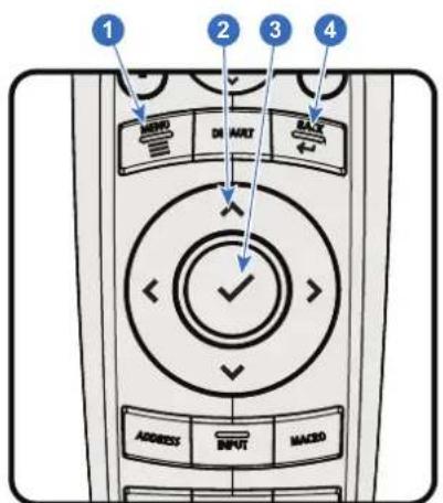
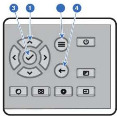
Image 5-6
To start up the menu structure, press MENU (1).
Use the arrow keys (Menu Navigation buttons) to navigate to the desired menu item (2). The background color changes to light blue.
Press the Menu Selection button (center key of the arrow keys), also called OK button, to activate that item and to jump one level deeper (3).
Use the numeral keys to enter values, or use the arrow keys to move the bar scale up or down.
Press the Back button to go up one level (4).
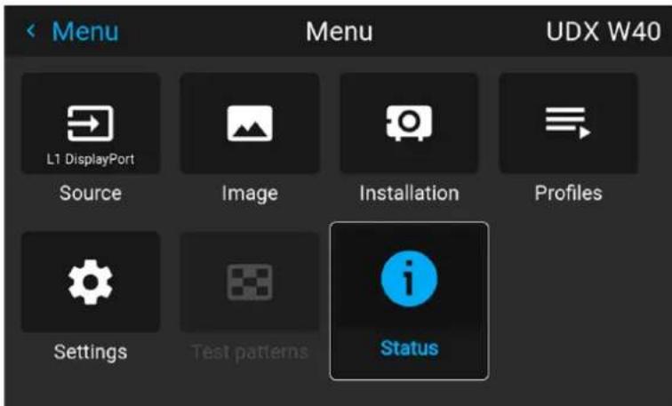
Image 5-7 Example of the home menu
Remark: a blue slider bar on the right side of the window means that there are more items to show than those currently displayed.
Define values
Menu settings are displayed using check boxes, bar scale sliders, and drop-down lists.
To set a value:
- Press OK to select or deselect a checkbox (turn a function ON or OFF).
- Use the arrow keys to move the bar scale slider up or down on the value line. For a bar scale 0-9, each step will equal 10% of the total value.
- To enter the value as a direct number, press OK, input the digit(s), and then press OK again to execute and exit cursor mode e.g. OK 79 OK.
Within an input field, use the * button as backspace button to remove an entered digit. Use the # button to enter a dot (.).
Changes to values are implemented dynamically.
To enter values with the local keyboard, use the arrow keys to select the first digit, press OK. Select the second digit and press OK. Continue until all digits are entered. Close the action by selecting the enter (↓) button and press OK. Select the backspace button and press OK to remove the last entered digit.
Using the LCD touch display
From Pulse software 2.0 onward, the touch display functionality of the LCD panel has been activated and can be used.
Instead of using the remote control buttons or keypad keys or button, you can now:
- Touch menu icons to enter the respective menu.
- Swipe a menu up and down if not all information is not immediately visible (e.g. more than 8 (sub)menu icons being visible)
- Return to a higher menu level, by touching the blue name in the top left corner of the display.
- Use touch functionality to use menu items (check boxes, sliders, digital keyboard or keypads, etc).
- Swipe menu panes left or right when multiple panes are available (e.g. the Status menu)
Menu memory
The OSD menu remembers the last selected sub-item as long as the projector is running. The menu memory is reset when restarting the projector from standby.
5.3 Test Patterns
List of standard test patterns
The test patterns that are available by default are the following:
- Aspect
- Focus-Green
- Focus-bursts
- White / Black/ Red / Green / Blue
• Cyan / Magenta / Yellow - Color bars
- Color gradients
- Checkerboard
- Cross hatch
- Geometry
• Horizontal gray bars - Vertical gray bars
- 3D Stereo
About the test pattern types
There are three types of test patterns possible in the projector:
| Type Explanation | Example of test pattern icon | |
| Standard test patterns | Standard test patterns. See previous list to see all test patterns available for your device. |  |
| Warped test patterns | Available from software 2.2 onward. Every test pattern will have “warped” variant available, symbolized with a “warp” symbol on the top-left corner of the icon.If active and configured, the warping will be applied to this test pattern. If warping is not active, or not configured, this will be identical to the standard test pattern. |  |
| Custom test patterns | If uploaded via an external tool, you will find your custom upload test patterns (and its warped variant) at the bottom of the list of available patterns.All custom uploaded test patterns will be marked with the default “test pattern file” icon. |  |
How to use test patterns
- In the main menu, select Test Patterns.
or
Push the Test Patterns button on the RC.
Image 5-8 Main menu, Test patterns
- In the Test pattern menu, select the desired test pattern from the list.
- To turn the test pattern off, select off instead.
Image 5–9 Test patterns menu, test pattern off
GUI - Source
6
6.1 Displaying a single source....58
6.2 Displaying multiple sources: Stitched layouts....58
6.3 Connector Settings 60
About the Source menu
This menu is used to select, review and configure sources into the projector.
6.1 Displaying a single source
About selecting a source
Before a source can be projected, the source signal must be connected to the source input(s) of the device and a valid synchronization signal must be available along with the source signal on at least one of the input connectors.
How to select?
- Press Menu to activate the menus and select Source.
Image 6-1 Main menu, Source
- Press OK.
The Select Source menu is displayed with the actual available sources filled out.
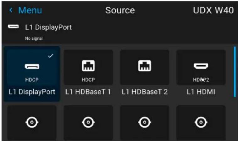
Image 6-2 Example of the input selection menu
- Select the desired input.
6.2 Displaying multiple sources: Stitched layouts
About stitched layouts
The first time you use a selected single source, the source will be displayed in the projector's native resolution. If the resolution of the source is different to the projector's resolution, the image is stretched or shrunk.
It is however possible to configure and display two or four source signals to make up one single image in full native resolution. This is called a Stitched Layout: the sources are stitched together.
The following table lists which stitched layouts you can use, and in which display mode these layouts can be used.
The table below describes the different Stitch Layouts and scan directions.
Type of layout Description
| 1 | : Single | A single source is displayed Quad Combo input: full screenSDI (4x)HDBaseT (2x)DisplayPortHDMIQquad DP 1.2 Input: DisplayPort (4x) | Mono / Active stereo |
| 1 | 2 | Two inputs are required. TheQuad DP 1.2 Input: sources are displayed next to 2x DisplayPort each other. | Mono / Active stereo |
| 1 | 2 | Four inputs are required. TheQuad Combo input: sources are displayed in four. 4x SDI input quadrants. Quad DP 1.2 Input: 4x DisplayPort | Mono / Active stereo |
| 3 | 4 | ||
| 1 | 2 | Four inputs are required. TheQuad DP 1.2 Input: sources are displayed next to 4x DisplayPort each other. | Mono / Active stereo |
| 1 | 2 | Two inputs are required. TheQuad DP 1.2 Input: sources are displayed one 2 x DisplayPort above the other. | Passive stereo |
| 1 | 2 | Four inputs are required. Two Quad DP 1.2 Input: sources are displayed next to 4x DisplayPort each other, while the other two are displayed above the first two | Passive stereo |
| 1 | 2 | 2 x Dual 1 x 2 |

Even if passive stereo sources are selected, the output of this projector can only be in either 2D or in Active Stereo. Advanced image processing will make sure a passive stereo image is properly converted to active stereo.
How to select a stitched layout
- Press Menu to activate the menus and select Source.
Image 6–3 Main menu, Source
- Press OK.
The Select Source menu is displayed with the actual available sources filled out, including all available stitched layout options.
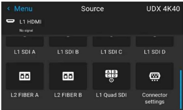
Image 6-4 Example of the stitched layout options
- Select the desired stitched input.

Tip: If the Quad DP input board is installed, scroll all the way down the menu for the stitched options on that board.
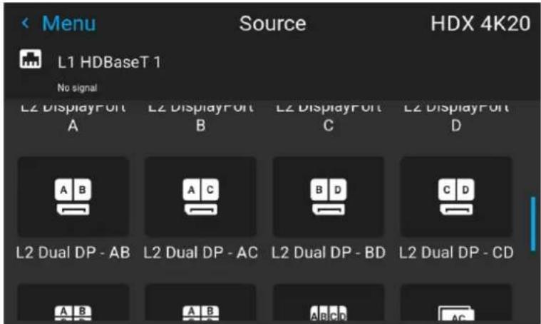
Image 6-5 Example of the stitched input options with the Quad DP board installed
6.3 Connector Settings
About Connector Settings
The Connector Settings menu allows you to change settings for each input connector of the projector.
By default all options for every connector are set to automatic, together with the native Extended Display Identification Data (EDID).
When entering the menu for each input connector, you can change the following:
- Color Space
- Signal Range
• EDID
How to configure a connector
- Press Menu to activate the menus and select Source.
Image 6-6 Main menu, Source
2. Press OK.
The Select Source menu is displayed with the actual available sources filled out.
- Scroll down to the bottom of the list of available sources and select Connector Settings.
Image 6-7 Source menu, connector settings
The available input connectors are displayed.
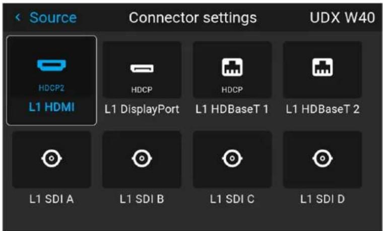
Image 6-8 Example of the Connector settings menu
4. Select the desired connector.
The Connector Settings menu for this connector will be displayed.
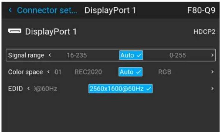
Image 6-9 Example of connector settings for an HDMI connector
-
You can change the following:
-
To force a limit on the used signal range, select one of the available signal ranges.
- To force a limit on the color space, select one of the available color spaces.
• To set a video timing other than the one native for the connector, select one of the options under EDID.

Note: You cannot change the EDID for SDI connectors.
GUI - Image 7
7.1 Setting image levels manually....64
7.2 Adjusting the sharpness....65
7.3 Adjusting the gamma correction....66
7.4 Setting the desired Gamma type....67
7.5 Digital Shift & Zoom 69
7.6 RealColor P7....73
7.7 Setting the output resolution....75
7.8 Displaying HDR content 76
7.9 Dynamic contrast....77
7.1 Setting image levels manually
Purpose
Contrast: Change the contrast of the complete output signal of the projected image.
Brightness: Change the brightness of the complete output signal of the projected image.
Saturation: Change the saturation of the complete output signal of the projected image.
How to set up Contrast
- In the main menu, select Image → Contrast.
Image 7-1 Image menu — Contrast
- Use the ◀ or ▶ key to change the contrast enhancement until the desired value is reached (adjustable between 0 and 2).
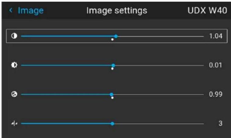
bar
| Image Settings | Value | | -------------- | ----- | | Category 1 | 1.04 | | Category 2 | 0.01 | | Category 3 | 0.99 | | Category 4 | 3 |Image 7-2 Example of the image sliders, contrast is the first slider
- If necessary, use the ▲ or ▼ key to select the other image adjustment options.
How to set up Brightness Level
- In the main menu, select Image → Brightness.
Image 7-3 Image menu — Brightness
- Use the ◀ or ▶ key to change the brightness until the desired value is reached (adjustable between -1 and 1).
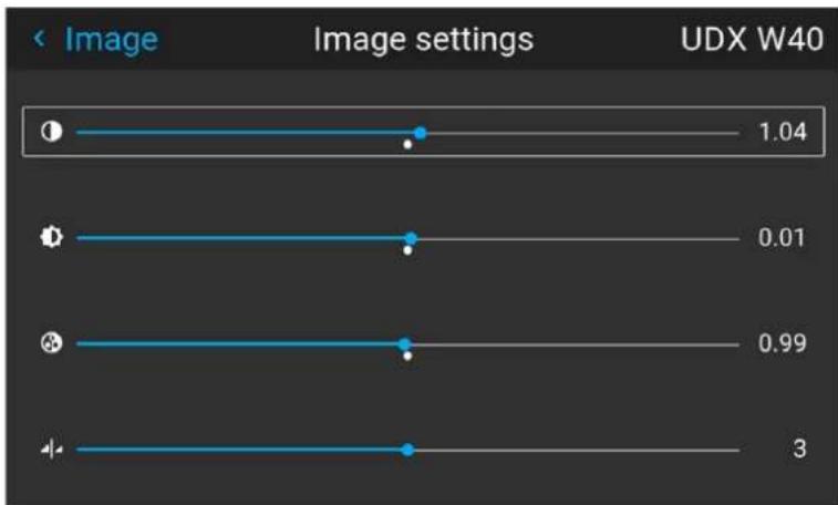
bar
| Image | Value | |-------|-------| | Image 1 | 1.04 | | Image 2 | 0.01 | | Image 3 | 0.99 | | Image 4 | 3 |Image 7-4 Example of the image sliders, brightness is the second slider
- If necessary, use the ▲ or ▼ key to select the other image adjustment options.
How to set up Saturation Level
- In the main menu, select Image → Saturation.
Image 7-5 Image menu — Saturation
- Use the ◀ or ▶ key to change the saturation until the desired value is reached (adjustable between 0 and 2).
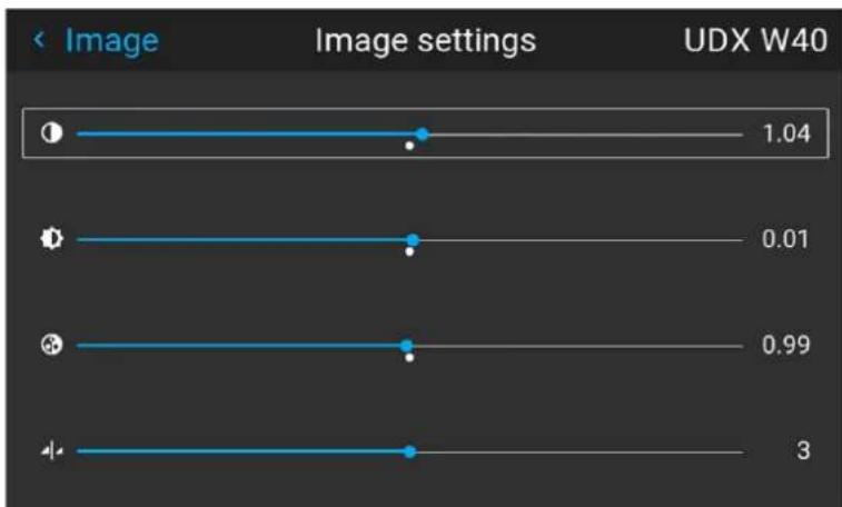
line
| Image Settings | Value | | -------------- | ----- | | 1.04 | 1.04 | | 0.01 | 0.01 | | 0.99 | 0.99 | | 3 | 3 |Image 7-6 Example of the image sliders, Saturation is the third slider
- If necessary, use the ▲ or ▼ key to select the other image adjustment options.
7.2 Adjusting the sharpness
About adjusting the sharpness
The sharpness adjustment amplifies the high frequency components in the picture. This means that by increase the sharpness, the picture will be perceived as sharper, and if decreased, the picture will be perceived as more blurry.
Increasing the sharpness will have the best effect in high contrast images, eg a table with text and borders. In a natural picture, high sharpness can be perceived as noise, as all details in the picture will be amplified. Available range: -2 to 8.
Default value: 0
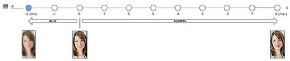
flowchart
graph LR
    A["-2 (min)"] --> B["-1"]
    B --> C["0"]
    C --> D["1"]
    D --> E["2"]
    E --> F["3"]
    F --> G["4"]
    G --> H["5"]
    H --> I["6"]
    I --> J["7"]
    J --> K["C (max)"]
    style A fill:#000,stroke:#fff,color:#fff
    style K fill:#000,stroke:#fff,color:#fff
    subgraph Time_Steps
        L["Blue"] --> M["Sharpen"]
    end
Image 7-7 Effect of sharpness adjust
How to adjust
- In the main menu, select Image → Sharpness.
Image 7-8 Image menu - Sharpness
- Use the ◀ or ▶ key to change the sharpness until the desired value is reached.
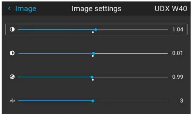
line
| Image Settings | Value | | -------------- | ----- | | 1 | 1.04 | | 2 | 0.01 | | 3 | 0.99 | | 4 | 3 |Image 7-9 Example of the image sliders, Sharpness is the bottommost slider
- If necessary, use the ▲ or ▼ key to select the other image adjustment options.
7.3 Adjusting the gamma correction
About gamma correction
Gamma correction is an image quality enhancement function that offers a richer image by brightening the already darker portions of the image without altering the brightness of the brighter portions (contrast feeling enhanced).
How to adjust
- In the main menu, select Image → Gamma.
Image 7-10 Image menu - Gamma
-
Use the ▼ key to select the slider.
-
Use the ◀ or ▶ key to change the gamma value between 1.0 and 2.8. The default value is 2,2.

Tip: The slider can be adjusted with a precision of 0.1.
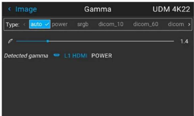
Image 7-11 Example of the gamma menu
7.4 Setting the desired Gamma type
About the alternate gamma types
Next to the standard gamma correction, the projectors can be manipulated in a way to simulate gamma types for other devices or purposes. This includes sRGB (standard Red-Green-Blue), Power gamma, DICOM gamma ranges and for simulation projectors sim1.
DICOM gamma ranges are usually reserved for medical displays. While this projector is not a certified DICOM display, it can simulate certain specific DICOM gammas at a few selected max light outputs. The DICOM gamma assumes that both ambient light and the projector outputs black as 0 cd/m^2 . Then there will be a few predefined gamma curves at the following light outputs:
• DICOM 10: 10 cd/m²
• DICOM 60: 60 cd/m²
• DICOM 180: 180 cd/m²
• DICOM 250: 250 cd/m²
• DICOM 300: 300 cd/m²
• DICOM 400: 400 cd/m²

This is the full list. Take into account that the available DICOM gamma types for your projector type may be more limited than this list.
Exception when using an HDR source
The only alternate color gamma that can not be selected in this menu is PQ/HDR. Because the color output of HDR is dependant on extra factors such as screen luminance, a separate menu has been made available for this (PQ).
If the source signal is HDR encoded an HDR icon will be visible next to the source signal. This is visible both the Source selection menu, as well as the status menu.
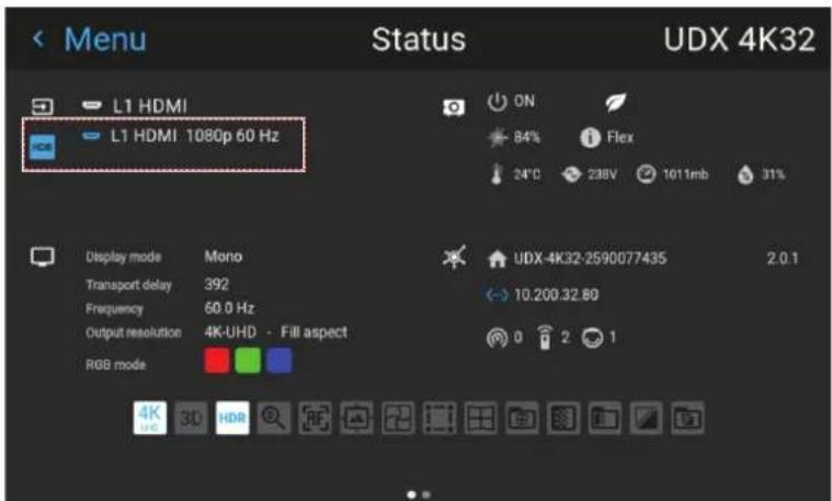
Image 7-12 Example of the HDR icon on the status menu
For more info on PQ and HDR, refer to "Displaying HDR content", page 76.
How to adjust the gamma type?
- In the main menu, select Image → Gamma type.
Image 7-13 Image menu - Gamma
The Gamma type menu is displayed. If source content is available, the detected gamma of the source will be displayed at the bottom of the menu.
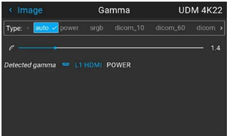
Image 7-14 Example of the gamma menu
- Use the ◀ or ▶ key to select the desired gamma type and confirm.
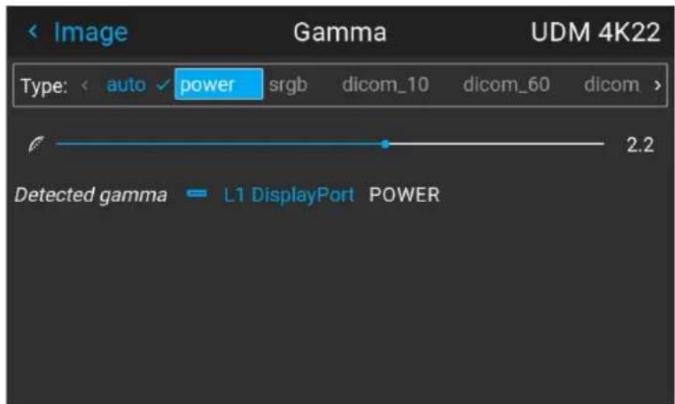
Image 7–15 Example of selecting a gamma type

Tip: If not sure what gamma type to select, keep the default value auto selected. This automatic mode will determine the used gamma type based on the incoming signal.
However: keep in mind when using the automatic mode, your media player needs to be configured correctly as well. While most mainstream media player devices will be configured correctly by default, we cannot guarantee this is the case for every device available on the market. If you notice the projected image seems "off", it may be necessary to check the configuration of your media player. For more info, check the user guide of your media player device.
7.5 Digital Shift & Zoom
What can be done?
The image can be optically shifted by using the vertical and horizontal lens shift.
If you want to reach a lens shift beyond what is possible with the optical shift, you can also perform a digital lens shift. This digital shift will occur on the DMD, rather than the lens holder. So take into account that this additional shift is minimal and restricted to the limits of the chip used.
For the optical zoom and lens shift, navigate to Home → Installation → Lens.

Lens shift is only possible when the used lens has been fully calibrated. To calibrate the current lens, navigate to System Settings → Maintenance → Lens Calibration.
The effect of Digital Zoom
This function zooms in the picture digitally. When zooming in, the center of the image will increase in size. This means that the outer part of the picture will be outside the picture frame. When zooming out, the result is that the picture will be smaller than the projectors picture frame. The area outside the rendered picture will then be black.
For an example, see the following photos. The red lines in the figures represent the DMD outline.

natural_image
Close-up of a koala with textured gray skin and visible eye, partially obscured by foliage (no text or symbols)Image 7-16 Originally picture, not digitally zoomed

natural_image
Close-up of a koala's face showing its distinctive nose and mouth (no text or symbols visible)
natural_image
Close-up photo of a koala with textured skin and visible eye, surrounded by foliage (no text or symbols)Image 7-17 Picture digitally zoomed in Image 7-18 Picture digitally zoomed out
The effect of Digital Shift
This function will shift the picture digitally, meaning that the picture will be moved in any direction. As a result, some parts of the picture might be shifted outside the DMD range.
For an example, see the following pictures. The red lines in the figures represent the DMD outline

natural_image
Close-up of a koala with visible facial features and open mouth, surrounded by foliage (no text or symbols)Image 7-19 Original Picture, not digitally shifted

natural_image
Close-up of a koala interacting with its face, showing its mouth and whisker (no text or symbols visible)
natural_image
Close-up photo of a koala with visible eye and mouth, no text or symbols presentImage 7-20 Picture shifted horizontally Image 7-21 Picture shifted vertically
Digital Shift & Zoom
- In the main menu, select Image → Digital Zoom Shift.
Image 7-22 Image menu, digital zoom and shift
The Digital Zoom Shift menu is displayed.
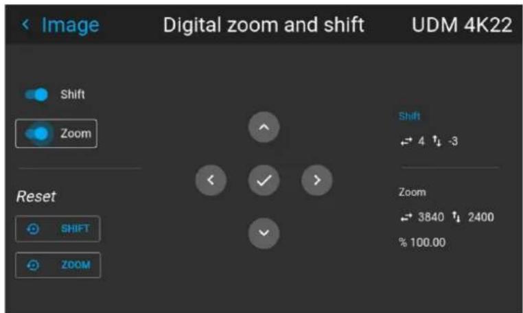
Image 7-23 Example of the digital zoom and shift menu
- In order to optimize the digital zoom, enable the Zoom slider. In order to optimize the digital shift, enable the Shift slider.
- When one or both of the modes are enabled, use the arrow keys to select the mini-keypad in this menu. Use the enter key to activate this mini-keypad.
If digital shift is enabled, the keypad will transform into the keypad for digital shift. If only digital zoom is active, it will automatically transform in they keypad for digital zoom.
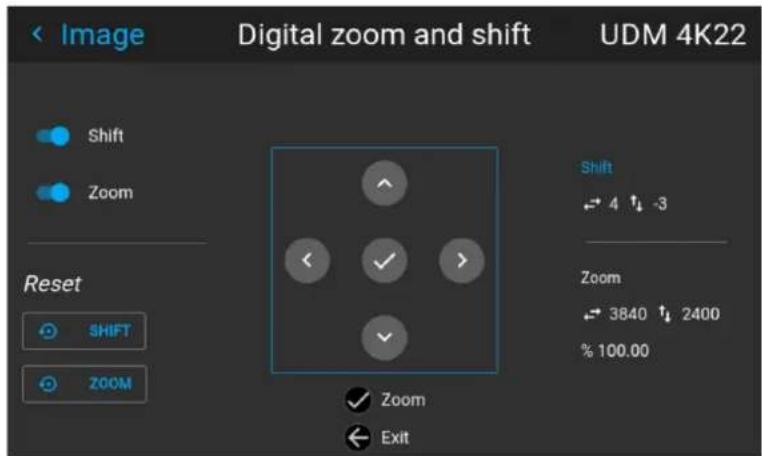
Image 7-24 Example of the enabled digital shift mode
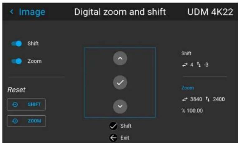
Image 7-25 Example of the enabled digital zoom mode
-
If digital shift is enabled, you can now do the following: • Use the ◀ or ▶ key to shift the lens (image) in horizontal direction.
-
Use the ▲ or ▼ key to shift the lens (image) in vertical direction.
- Use the enter key to transform the keypad to digital zoom mode (if enabled).
-
Use the return key to exit without saving.
-
If digital zoom is enabled, you can now do the following:
-
Use the ◀ or ▶ key to zoom the lens in or out.
- Use the enter key to either finish digital shift and zoom.
- Use the return key to exit without saving.
7.6 RealColor P7
Purpose
When blending images from multiple projectors, the measured color coordination of each projector can be altered to a desired common level. This so that the projected colors are identical over all projectors used.
Alternatively, if you are unfamiliar with how to adjust the colors to a specific setting, there are also a certain number of presets available, which forces the color output to specific color standards.
How to set custom P7 values
- In the main menu, select Image → Advanced → RealColor P7.
Image 7-26 Advanced settings menu - RealColor P7
The P7 menu is displayed.
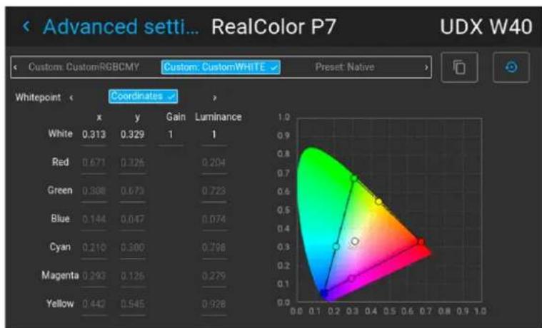
heatmap
| Whitepoint | x | y | Gain | Luminance | | ---------- | ---- | ---- | ---- | --------- | | White | 0.313| 0.329| 1 | 1 | | Red | 0.671| 0.325| 0.204| | | Green | 0.308| 0.673| 0.723| | | Blue | 0.144| 0.047| 0.074| | | Cyan | 0.210| 0.300| 0.798| | | Magenta | 0.293| 0.125| 0.279| | | Yellow | 0.442| 0.545| 0.928| |Image 7-27 Example of the RealColor P7 menu, here on a UDX
-
Select the desired Custom Mode. Select one of the following Custom options and confirm:
-
Custom RGB: 3-point color configuration.
In RGB mode, the C, M and Y coordinates will be calculated automatically based on the R, G and B coordinates. - Custom RGBCMY: 6-point color configuration (both RGB and CMY).
In RGBCMY mode, each color can be given a specific coordinate within the measured color triangle. -
Custom WHITE: Configure only the White temperature.
-
Choose how to determine the Whitepoint. Choose one of the following:
- Coordinates: Configure the white point via specific coordinates.
The white point is specified using an x, y coordinate in the CIE 1931 Chart.
GUI - Image
• Temperature: Configure the white point via a color temperature slider.
The white point is specified on a Kelvin scale between 3200K and 13000K tracking along the black body curve.
- Define the coordinates for each available color.
Click on a coordinate value and select the current value. Enter the desired value with the numeric keys.

Note: You can only pick coordinates within the measured color triangle.

You can reset all coordinates to the default values (to native) by clicking the Reset icon.

How to choose one of the P7 presets
- In the main menu, select Image → Advanced → Realcolor P7.
Image 7-28 Advanced settings menu - RealColor P7
The P7 menu is displayed.
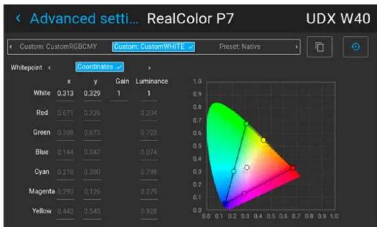
radar
| Whitepoint | x | y | Gain | Luminance | | ---------- | ---- | ---- | ---- | --------- | | White | 0.313| 0.329| 1 | 1 | | Red | 0.671| 0.826| 0.204| 0.204 | | Green | 0.398| 0.673| 0.723| 0.723 | | Blue | 0.144| 0.047| 0.074| 0.074 | | Cyan | 0.210| 0.300| 0.798| 0.798 | | Magenta | 0.293| 0.126| 0.279| 0.279 | | Yellow | 0.442| 0.545| 0.928| 0.928 |Image 7-29 Example of the RealColor P7 menu
-
Select one of the pre-defined presets:
-
Standard: A color standard for all UDX projectors, which may be considered the new native settings for all UDX projectors. Default for UDX.
- Native: Projector native color settings.
• DCI-P3: Color standard for Cinema.
• EBU: European color standard for broadcasting. - SMPTE-C: American color standard for broadcasting.
• Rec. 709: Color standard for high-definition televisions (HDTV).
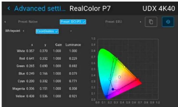
radar
| | x | y | Gain | Luminance | | ------ | ----- | ----- | ------ | --------- | | White | 0.357 | 0.370 | 1.000 | 1.000 | | Red | 0.641 | 0.332 | 1.000 | 0.229 | | Green | 0.265 | 0.690 | 1.000 | 0.692 | | Blue | 0.249 | 0.166 | 1.000 | 0.079 | | Cyan | 0.200 | 0.332 | 1.000 | 0.771 | | Magenta| 0.336 | 0.151 | 1.000 | 0.308 | | Yellow | 0.438 | 0.536 | 1.000 | 0.921 |Image 7-30 Example of one of the presets, here DCI-P3

Note: After choosing one of the presets, you can still alter the values of the coordinates to your own choosing, similarly to how you set custom P7 values.
Use the Reset icon to return to the default values of the chosen preset.
7.7 Setting the output resolution

This menu is only available on the 4k models, with an actuator included.
How to determine the desired output resolution for my content
While the native output resolution of this projector is 4K in Ultra-High Definition (4K-UHD), sometimes it can be better to choose an alternate resolution, depending on the main purpose of the projected content:
- If the main purpose of the projection is image (e.g. photographs, movie, or similar purpose), use the 4K UHD output resolution for the best image at the highest possible light output.
- If the main purpose of the projection is text (e.g. spreadsheets, presentations, or similar purposes), use the 4K UHD S output resolution for the for the most stable and sharpest possible output.
- If the main purpose of the projection is HFR video (content with high framerate, e.g. racing games), use the WQXGA output resolution. This will disable the actuator and allow content of up to 120 FPS to be played.
How to choose the output resolution
- In the main menu, select Image → Advanced → Output resolution.
Image 7-31 Advanced settings menu, Output resolution
The Output resolution menu is displayed.
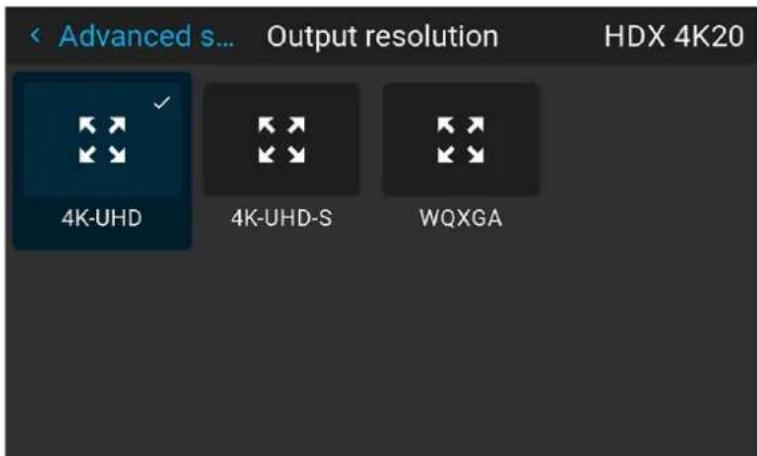
Image 7-32 Example of the available output resolutions
2. Select the desired output resolution.
Possible resolutions:
• 4K UHD: 4k images, using the actuator at normal frequency.
• 4K UHD S: 4k extra sharp images, using the actuator at a higher frequency
- WQXGA: 2k images. In this mode, the actuator is disabled.
7.8 Displaying HDR content
About HDR and PQ
Perceptual Quantizer (PQ) is a non-linear electro-optical transfer function (EOTF) that allows for the display of High Dynamic Range (HDR) content with a luminance level of up to 10 000 cd/m² and can be used with the Rec. 2020 color space.
When do I know my content is HDR encoded?
If the source signal is HDR encoded, an HDR icon will be visible next to the source signal. This is visible both in the Source selection menu, as well as the status menu.
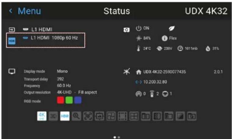
Image 7-33 Example of the HDR icon on the status menu
How to properly display HDR content?
If your provided HDR content has been mastered with PQ (e.g. HDR10 and Dolby Vision), a few changes can be made in order to project the intended mastering on screen. These changes are necessary because HDR content has been mastered specifically for HDR capable displays that are watched in living rooms. These conditions are different from a non-HDR projector and darker cinema-like environments.
The projected HDR content depends on the following factors:
- Mastering luminance: This is content-specific and cannot be changed.
- Screen luminance: Every projection screen has a specific luminance (measured in nits or foot-Lambert). Entering this luminance in the projector will adapt the content towards the intended HDR result.
- HDR Boost: A variable "booster" that may amplify or downplay the HDR output.
How to set the HDR-related parameters?
- Make sure the chosen Gamma Type is set to AUTO. For more info, refer to "Setting the desired Gamma type", page 67.
- In the main menu, select Image → Advanced → HDR.
Image 7–34 Advanced settings menu, HDR
The HDR menu is displayed.
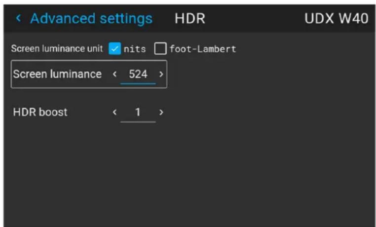
Image 7–35 Example of the HDR menu
- Select the desired Screen luminance unit (nits or foot-Lambert).
- Enter the Screen luminance (which is measured in nits or foot-Lambert).
- Alter the HDR boost if necessary. You can modify this value to somewhere between 0.8 and 1.2.
7.9 Dynamic contrast
About dynamic contrast
Projectors rely on contrast to showcase dark scenes or black parts on the projected surface. Whites and light areas are usually projected without issue, but blacks and dark areas are a different matter. With low contrast, blacks and dark areas appear more grey. The dynamic contrast menu is here to improve the dark scene accuracy.
Dynamic contrast checks the projected content dynamically and adapts the power of the light source accordingly to create the best possible outcome.

Take note that dynamic contrast isn't magic. Adapting the light source to adapt its contrast according to the played content will have an impact on the total light output of the projector. If you do not care about this feature and want your projector to display the brightest possible content instead, you can turn this feature off.
How to set the dynamic contrast?
- In the main menu, select Image → Advanced → DynaBlack.
Image 7-36
The DynaBlack menu is displayed.
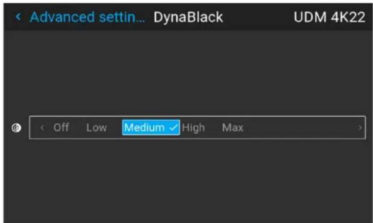
Image 7-37 Example of the DynaBlack menu
- Select the desired dynamic contrast setting, or leave the default on (medium).
The result will slowly become visible.

Do not panic if there isn't a visible change after a few seconds. Each change in the dynamic contrast menu has an impact on the light source, thus these changes will only become visible over time.
GUI - Installation
8
8.1 Configuring the lens, optical zoom-focus 80
8.2 Configuring the lens, shift 80
8.3 Configuring the lens, dynamic focus....81
8.4 Configuring the lens, Shift to center....82
8.5 Configuring the lens, tilt sensor 83
8.6 Laser ranging 84
8.7 Manipulating the rigging frame 85
8.8 Manipulating the rigging frame, center position 87
8.9 Orientation....87
8.10 Scaling modes....88
8.11 Warping....89
8.12 Blending & masking 102
8.13 Illumination 112
8.14 3D projection.... 113
8.1 Configuring the lens, optical zoom-focus
What can be done?
If a motorized lens has been mounted onto the projector, you can fine-tune the projected image.
Zoom - Focus
- In the main menu, select Installation → Lens → Zoom focus.
Image 8-1 Lens menu, Zoom & Focus
The Zoom and focus menu is displayed.
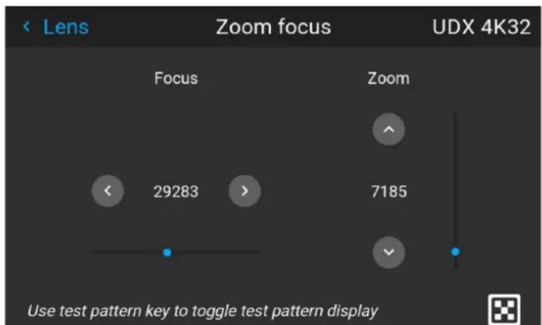
Image 8-2 Example of the zoom and focus adjustment menu
- Use the ▲ or ▼ key to zoom the lens in or out.
Use the ◀ or ▶ key to focus the lens to far or near.
8.2 Configuring the lens, shift
What can be done?
The image can be optically shifted by using the vertical and horizontal lens shift.
If you want to reach a lens shift beyond what is possible with the optical shift, you can also perform a digital lens shift. This digital shift will occur on the DMD, rather than the lens holder. So take into account that this additional shift is minimal and restricted to the limits of the chip used.
For the digital zoom and shift, navigate to Home → Image → Digital Zoom Shift. For more info, see “Digital Shift & Zoom”, page 69.

Optical lens shift is only possible when the used lens has been fully calibrated. To calibrate the lens, navigate to System Settings → Maintenance → Lens Calibration.
Vertical and Horizontal Shift
- In the main menu, select Installation → Lens → Shift.
Image 8-3 Lens menu, lens shift
The Lens shift menu is displayed.
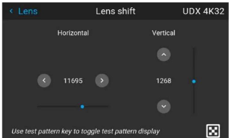
Image 8-4 Example of the lens shift menu
- Use the ◀ and ▶ keys to shift the lens (image) in horizontal direction.
Use the ▲ and ▼ keys to shift the lens (image) in vertical direction.
8.3 Configuring the lens, dynamic focus
About focus drift and dynamic focus
Due to the design of TLD+ lenses and ultra-short throw lenses (UST lenses), these type of lenses tends to heat up over time when used in projectors. This has the side-effect of a slight shift in focus between the lens in its cold state and the lens in its heated state, which is referred to as "focus drift".
While there are external solutions available that perform a "focus drift compensation", a dynamic focus feature has been implemented from Pulse software version 2.0 onward that handles this focus drift. While enabled, the projector will perform the necessary calculations in order to handle this drift in focus.

The amount of focus drift can differ between lenses. For that reason it is important to calibrate the focus drift when a new lens is mounted in the projector.
Use the calibration wizard in the Projector Toolset to calibrate focus drift. For more info on the focus drift calibration, consult the Projector Toolset user guide.
How to enable dynamic focus?
- To enable dynamic focus mode, select Installation → Lens.
The Lens menu is displayed.
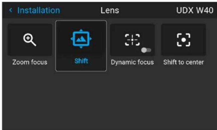
Image 8-5 Example of the Lens menu
- In the Lens menu, click Dynamic focus to toggle between On and Off.
Image 8-6 Lens menu, Dynamic focus enabled Image 8-7 Lens menu, Dynamic focus disabled

Note: The Dynamic focus slider is only visible when the light source is on.
8.4 Configuring the lens, Shift to center
What can be done?
The lens can be forced back to the center position by selecting Shift to center.
How force lens in Mid position
- To force lens in Mid position, select Installation → Lens → Shift to center.
Image 8-8 Lens menu, Shift to center
- Confirm by pressing the CONFIRM button.
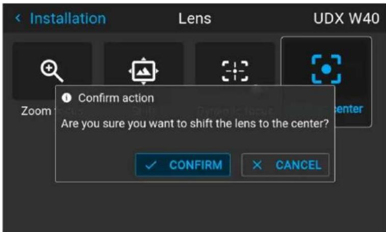
Image 8-9 Example of the Shift to center action
The lens will calibrate itself and return to the center position.
8.5 Configuring the lens, tilt sensor
When to use the tilt sensor menu
The projector has a built-in tilt sensor that detects the angle at which the projector is mounted. If you are in a situation where you need to fine-tune the projector because you want to achieve a picture at a specific angle (e.g. perfectly level, or a perfect fit in a multi-projector setup), you can use the tilt sensor menu as an aide when adjusting the projector feet, rigging frame or other used mounting mechanisms.
How to read the tilt sensor values
- In the main menu, select Installation → Lens → Tilt sensor.
Image 8-10 Lens menu, Tilt sensor
The Tilt sensor menu is displayed.
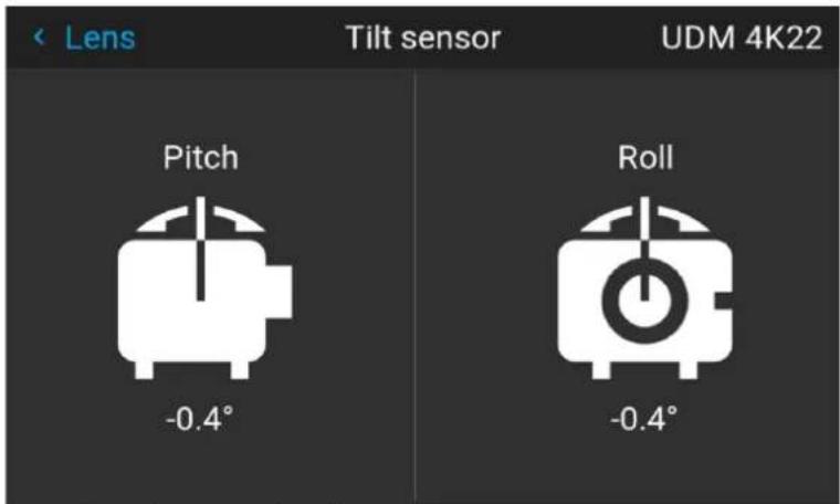
Image 8-11 Example of the tilt sensor menu

If you notice the tilt sensor isn't working correctly (e.g. when compared to a level), you can calibrate the sensor in the settings menu. For more info, see "Advanced settings – Tilt sensor calibration", page 165.
8.6 Laser ranging
What can be done?
When the optional laser range finder is installed on the projector, you can use the laser source to measure the distance between the front of the projector and the surface you are projecting on.
This can help you fine-tune the position of the projector.

Take into account that while a laser ranging session is active, the projected image will be off. This to have no interference between laser pointer and projected image. Instead, a red border will be projected giving the outline of where the projected image should be.
How to manipulate the laser range finder?
- In the main menu, select Installation → Laser ranging.
Image 8–12 Installation menu, laser ranging
The Laser ranging menu is displayed.
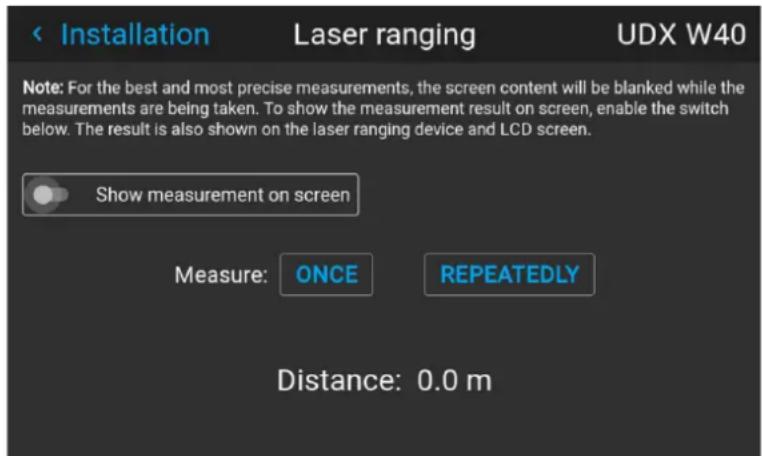
Image 8–13 Example of the laser ranging menu
- For a single laser ranging calculation, press Once. This will continue the laser for 30 seconds.
- If you want a continued laser ranging (e.g. when fine-tuning the position of the projector), press Repeatedly.
- If you cannot see the display of the laser range finder while performing a laser ranging session, select Show measurement on screen. This way, the measurement will be projected alongside the laser dot and the red border.
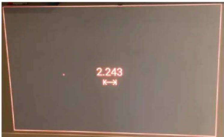
Image 8–14 Example of projected image during laser ranging session with measurement on screen

By default the measurement is in meters. If you want the distance projected in feet, you can change the measurement system in the System settings menu. For more info, refer to "Units (measurement) system setup", page 140.
8.7 Manipulating the rigging frame
When can you manipulate the rigging frame?
You can manipulate the rigging frame in the Pulse menu when:
- The projector is mounted in a motorized rigging frame.
- The wiring of the motorization is connected to the projector, including the XLR connector.
- The XLR connector is enabled and powered to 24V. For more info on how to power the XLR connector, see "Front XLR output voltage control", page 137.
How to manipulate the rigging frame?
- In the main menu, select Installation → Lens → Motorized frame.
Image 8-15 Lens menu - Motorized frame
The Motorized frame menu is displayed.
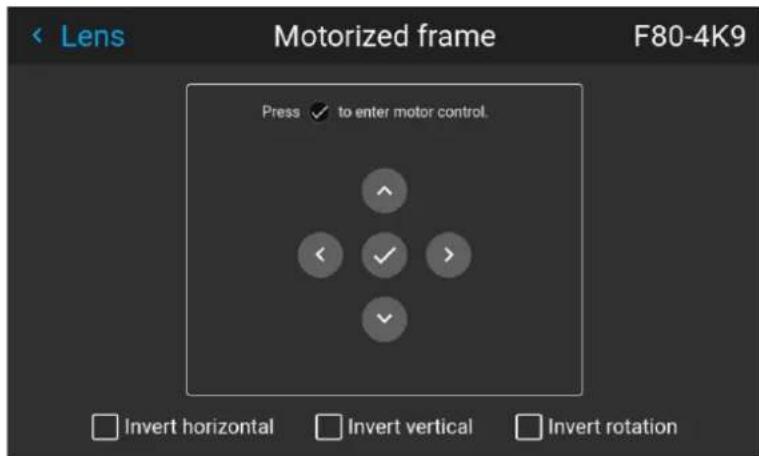
Image 8-16 Example of the Motorized frame menu
- Press the OK key or button to activate the frame shift motors.
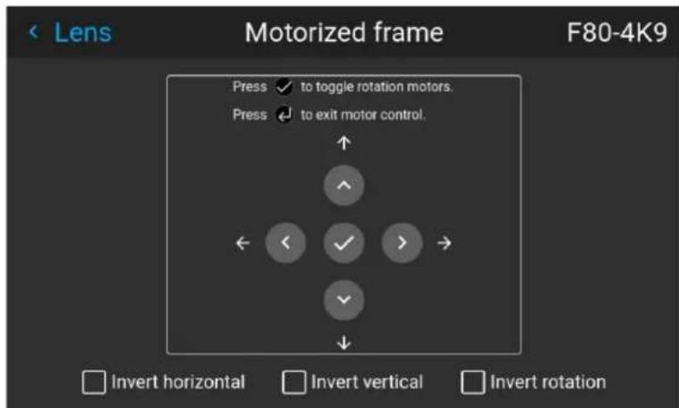
Image 8-17 Example of horizontal and vertical frame shift
- Use the ▲ or ▼ button to shift the rigging frame (image) in vertical direction.
Use the ◀ or ▶ button to shift the rigging frame (image) in horizontal direction.
- Confirm with the OK button.
The frame rotation menu is displayed.
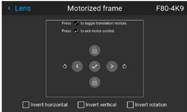
Image 8-18 Example of frame rotation
-
Use the ◀ or ▶ button to rotate the rigging frame (image) either clockwise or counterclockwise.
-
Confirm with the OK button to return to the frame shift menu, or use the Menu back button to return to the Lens menu.
8.8 Manipulating the rigging frame, center position
What can be done?
The motorized frame can be forced back to the center position by selecting Center motorized frame.
How to reset the motorized frame?
- In the main menu, select Installation → Lens → Center motorized frame.
Image 8-19 Lens menu, Center motorized frame
A confirm action prompt will be displayed.
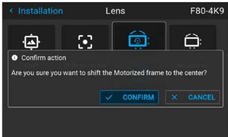
Image 8-20 Example of the Center motorized frame action prompt
- Confirm to reset the frame to its center position.
Wait until the frame motors have stopped before doing other actions.
8.9 Orientation
What can be done?
The way of physical installation of the projector can be defined to the projector.
The following installation are possible:
- Desktop front: Projected image will not be flipped or mirrored.
- Desktop rear: Projected image will be flipped horizontally (left side switches to the right side).
• Ceiling front: Projected image will be flipped vertically (top side switches to the bottom side). - Ceiling rear: Projected image will be flipped both vertically and horizontally.
- Auto front: The tilt sensor will detect if the projector is desktop or ceiling mounted and will project a readable image accordingly.
- Auto rear: The image will be flipped horizontally. The tilt sensor will detect if the projector is desktop or ceiling mounted and will project a readable image accordingly.
How to set the correct orientation
- In the main menu, select Installation → Orientation.
Image 8-21 Installation menu, orientation
The Orientation menu is displayed.
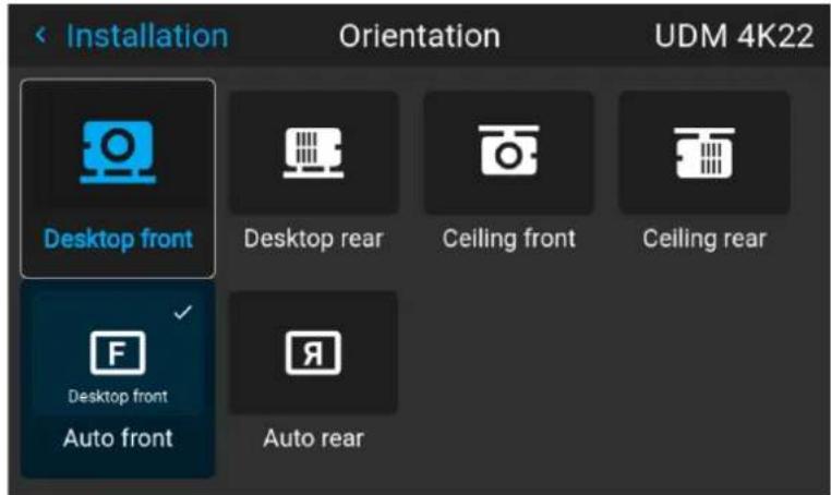
Image 8-22 Example of the orientation menu
- Use the ◀ or ▶ keys to select the projector orientation mode and press OK to activate.
8.10 Scaling modes
About scaling modes
While the default mode of projection is to fill the screen while respecting the aspect ratio (fill aspect), it is also possible to stretch the image in a different way. You can choose from one of the following scaling methods:
| Scaling Mode | Explanation Example image | 1 |
| Fill aspect Default scaling mode. Stretches the image to the native resolution of the DMD, while respecting the original aspect ratio. | 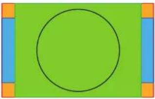 | |
| 1:1 An exact rendering of the source signal, which may be smaller than the native resolution | 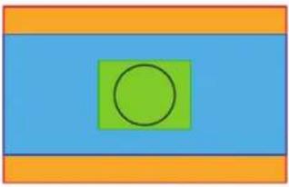 | |
| Scaling Mode | Explanation Example image | 2 |
| Fill screen Fills | the screen to the screen size defined in the Screen Size menu, while respecting the original aspect ratio. For more info on adjusting the Screen Size menu, $ “Warping - Screen Size”, page 90. | 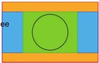 |
| Stretch This mode stretches the image to the screen size defined in the Screen Size menu, while ignoring the original aspect ratio. For more info on adjusting the Screen Size menu, see “Warping - Screen Size”, pa 90. | 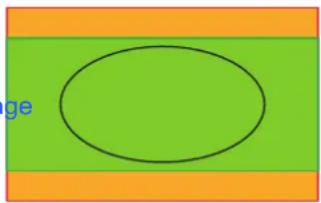 | |
Setting a scaling mode
- In the main menu, select Installation → Scaling.
Image 8–23 Installation menu, scaling
The scaling mode menu is displayed.
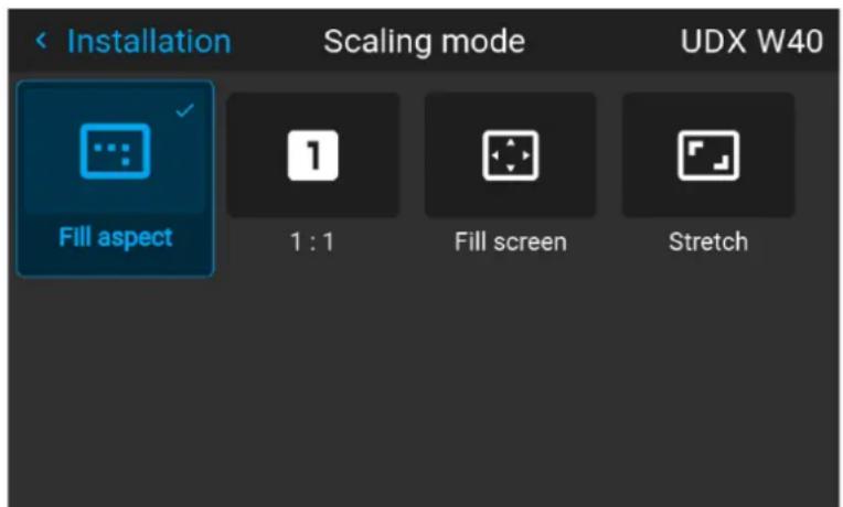
Image 8-24 Example of the scaling mode menu
- In the Scaling menu, select the desired scaling mode and confirm.
8.11 Warping
About warping
Image warping is the process of digitally manipulating an image to compensate for the distortion of the screen. Consequently, it can also be used to generate an image with irregular shape.
While an image can be transformed in various ways, pure warping doesn't affect the colors.
8.11.1 Warping - On/Off
About warping on/off
By toggling between on and off the warping functionality can be enabled or disabled.
How to toggle
- In the main menu, select Installation → Warp.
Image 8–25 Installation menu, warp
The Warp menu is displayed.
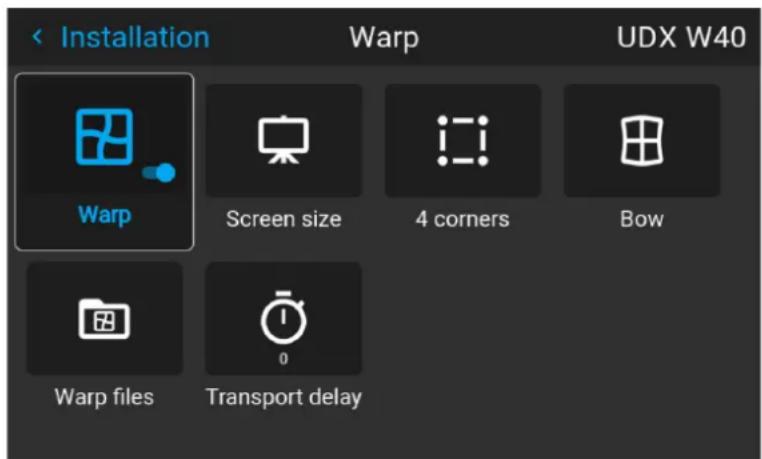
Image 8–26 Example of the Warp menu
- In the Warp menu, click Warp to toggle between On and Off.
Image 8–27 Image 8–28
8.11.2 Warping - Screen Size
About (Warp) Screen Size adjustment
If the used source aspect ratio is different than the projector aspect ratio (e.g. source is 16:9 and projector is 16:10), then black bars will be projected. In this example case a black bar on top and bottom of the image will be projected. The warp area contains not only the image information but also the black bars.
If we want to position (e.g. the active left top corner exactly on the screen using 4 corner warp), then it is very hard to do that as we are moving the black left top corner and we do not have control over the exact position image left top corner. By moving the outline of the warp screen size to the active image information, the corner points of the warp area are now exactly on the corner points of the active image information and makes warping much easier.
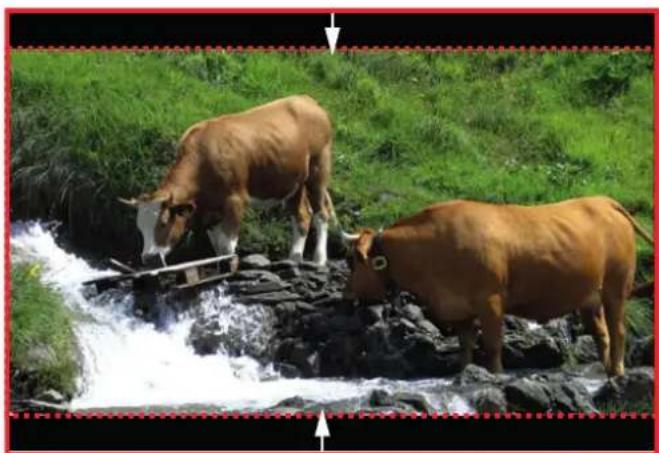
natural_image
Two cows grazing on a rocky stream surrounded by green grass (no text or symbols visible)Image 8–29 Warp outline example
Using the screen aspect ratio presets
- In the main menu, select Installation → Warp → Screen Size.
Image 8-30 Warp menu, screen size
The Screen Size menu is displayed.
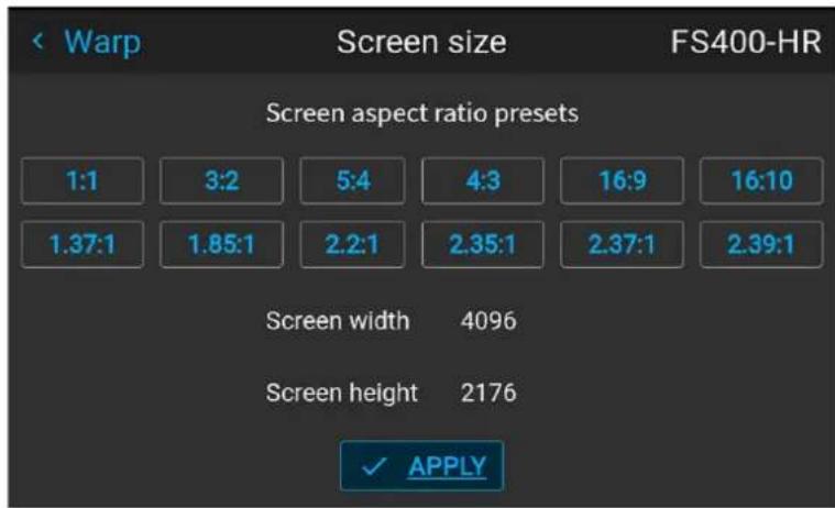
Image 8-31 Example of the screen size menu
- Click on one of the predefined presets for the screen aspect ratio.
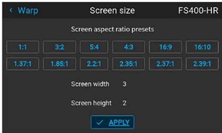
Image 8-32 Example of the screen size menu, with preset "3:2" selected.
The selected ratio is filled out next to Screen width and Screen height.
3. Click Apply.
How to adjust the image with pixels?
- In the main menu, select Installation → Warp → Screen Size.
Image 8-33 Warp menu, screen size
The Screen Size menu is displayed.
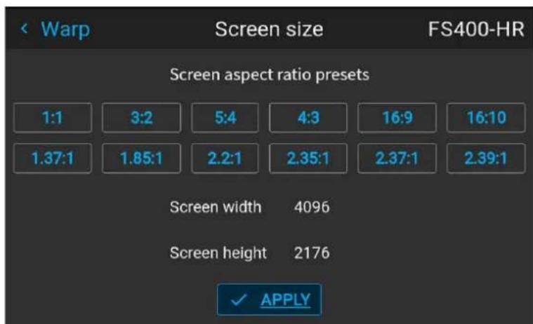
Image 8-34 Example of the screen size menu
- Select either Screen width or Screen height.
- Set the new value to shrink either the width or height of the warp outline so that the outline is equal with the active source.
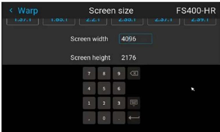
Image 8-35 Example of the Screen size menu, editing the screen width

Tip: A red border will be projected along with the current image. The border is a visual tool, showing the result of the adjusted outline.
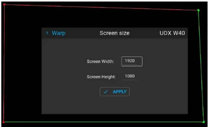
Image 8-36

Tip: The value can also be entered by the numeric keys on the remote control. Press * to delete existing numbers, and enter the new value by the numeric keys.
4. Click Apply.
8.11.3 Warping - 4 corners adjustment
About 4 Corners adjustment
4 corner adjustment is typically used when the mechanical installation of the projector prevents it from pointing perpendicularly at the screen. For example, you can overshoot the screen and use 4 corner adjustment to pull your projected image corners back into the screen.
Some examples:
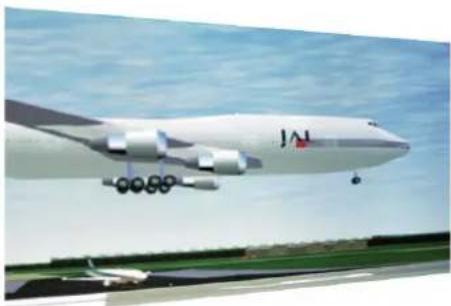
natural_image
Exterior view of a large cargo aircraft in flight with landing gear deployed (no visible text or symbols)Image 8-37 4 corner adjustment
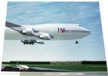
natural_image
Exterior view of a large JAM aircraft in flight over an airport runway, with no visible text or symbols on the aircraft or surroundings.How to adjust the image?
- In the main menu, select Installation → Warp → 4 Corners.
Image 8–38 Warp menu, 4 corners
The 4 corners menu is displayed.
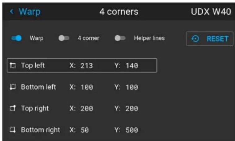
Image 8–39 Example of the 4 corners menu
- To enable 4 Corners warping, enable the 4 corner slider.
- To have a visual representation of what your warp will look like, enable the Helper lines slider.
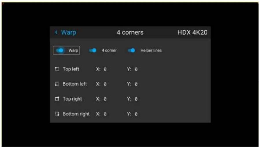
Image 8-40 Example of 4 corners warping menu, with helper lines active on the edges of the screen
- To set warping on one of the four corners, select one of the four corners and confirm.
- Set the desired X and Y coordinates for this corner, using the arrow keys, and confirm.
After confirming, the helper lines for that corner will jump to the entered XY coordinate (if helper lines were enabled).
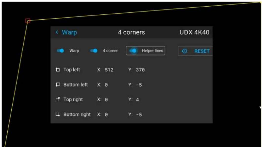
Image 8-41 Example of the 4 corners menu, with 4 corner warping and helper lines enabled
- Repeat from go to step 4 for each corner, until all corners are warped in the desired position.

To reset the 4 corner adjustments, select Reset and press the OK button.
8.11.4 Warping - Bow
About bow adjustment
A bow distortion can be adjusted so that a normal image is displayed. Positive adjustments introduce more outside bow distortion. Negative adjustments introduce more inside bow distortion.
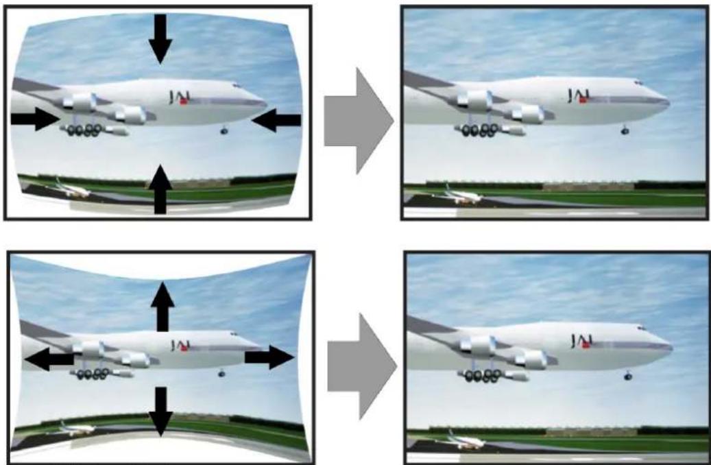
Image 8-42 Bow distortion
Definition of angle and linearity (length) in the bow warp procedure
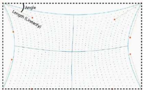
Image 8-43
Symmetric bow correction
- In the main menu, select Installation → Warp → Bow.
Image 8-44 Warp menu, Bow
The bow menu is displayed.
-
To enable bow correction, make sure the Bow slider is enabled (visible by the blue highlight).
-
To perform a symmetric adjustment, make sure the Symmetric slider is set to On (visible by the blue highlight).
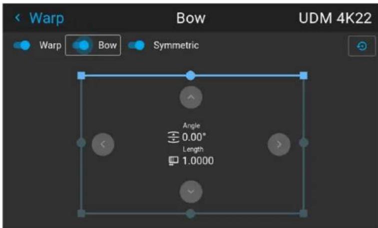
Image 8-45 Both the Bow and Symmetric sliders are set to on
- Use the arrow keys to select the helping lines that represent the picture and confirm.
The helping lines that represent the projected picture are now colored blue, while the others are colored white.
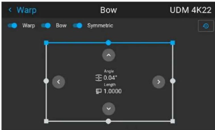
Image 8-46 The upper line is colored blue, the other sides are colored white
- Use the arrow keys to select the side of the picture that needs a correction and confirm.
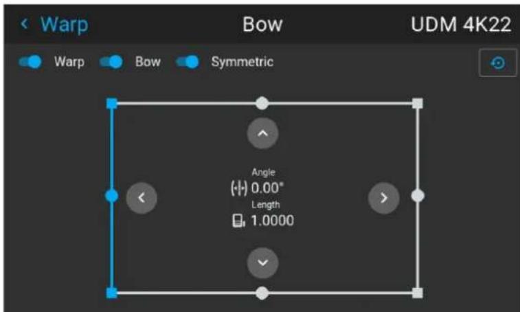
Image 8-47 Symmetric bow correction
- Use the arrow keys to adjust the angle and linearity (length) of the vectors. Press enter to confirm and switch between angle and length.

Tip: The angle is adjusted by using the up and down arrow keys. The linearity is adjusted by using the left and right arrow keys.
The correction will occur symmetrically on each side of the center of the highlighted side.
- Repeat this step for all sides of the picture that has to be corrected, until the desired transformation has been achieved.
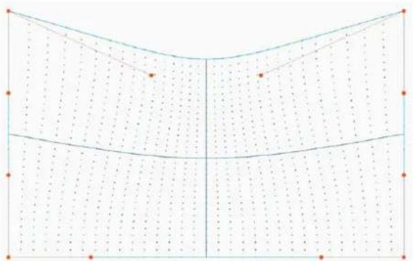
natural_image
Pure geometric diagram with grid lines and dots, no text or symbols presentImage 8-48 Example of a symmetric bow correction
Asymmetric bow correction
- In the Bow menu, enable the Bow slider and disable the symmetric slider.
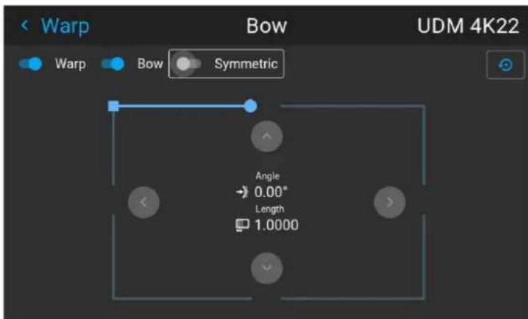
Image 8-49 Example of the bow menu, with the Symmetric slider disabled
There are now two vectors on each side of the picture that can be adjusted individually.
- Use the arrow keys to select the helping lines that represent the picture and confirm.
The helping lines that represent the projected picture are now colored blue, while the others are colored white.
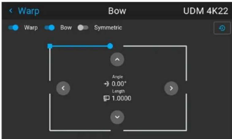
Image 8–50
- Select the desired slider and confirm.
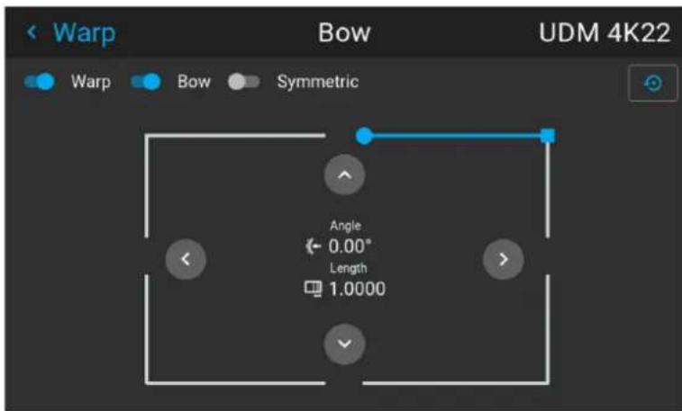
Image 8-51
- Adjust angle and linearity (length) individually to obtain the correct correction. Press enter to confirm and to switch between angle and length.

Tip: Adjust the angle by using the up and down arrow keys. Adjust the linearity by using the left and right arrow keys.
-
Repeat the previous steps for each side of the picture that must be corrected.
-
When completed, a transformation will occur in a way similar to the following example. Observe that the upper side of the picture now has an asymmetric correction.
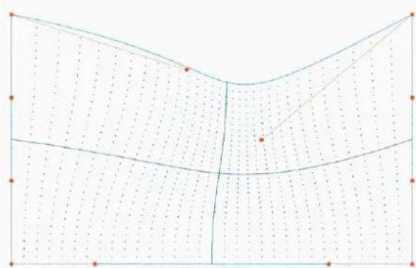
natural_image
Pure geometric diagram with grid lines and dots, no text or symbols presentImage 8-52 Example of an asymmetric bow correction

To reset the bow adjustments, select Reset and confirm.
8.11.5 Warping - Warp files
About custom Warp Files
Next to setting your specific warp configuration in the GUI, you can also upload or download a custom warp grid in XML format to/from the projector. This is a time-saving option when multiple projectors need an identical Warp configuration.
To upload or download warp files you can use Projector Toolset or Prospector tool to upload/download the warp grid in the format of an XML file. Alternatively, you can contact the "file endpoint" directly via the curl program or some other tool that supports http upload.
For more information on uploading/downloading Warp files using the Projector Toolset, refer to the Projector Toolset user manual.
For more information on uploading/downloading Warp files using curl or other tools that supports HTTP upload, refer to the Pulse API Reference Guide.

When uploading a warp file that is too big, or with warp parameters outside the limits of the projector, some irregularities can occur. It will show up in two ways:
1: No warp enabled, picture still unwarped.
2: Distortions and artifacts in the edges of the picture.
There will be no error messages or warnings in the display when this occurs. The above mentioned symptoms is the only indication of this case.
How to activate an uploaded Warp grid?
- In the main menu, select Installation → Warp.
Image 8–53 Installation menu, Warp
- In the Warp menu, select Warp files.
Image 8–54 Warp menu, Warp files
The Warp Files menu is displayed.
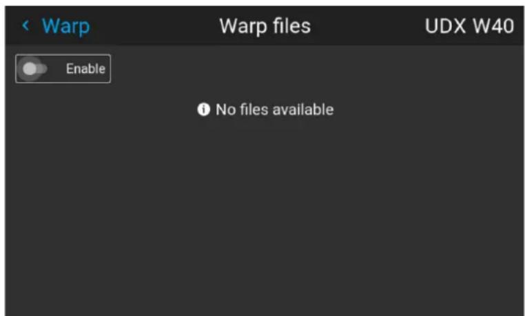
Image 8–55 Example of the Warp files menu
- Make sure the Enable slider is set to right.
- Select the desired warp file.
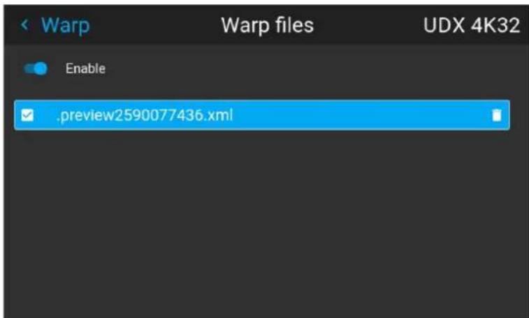
Image 8-56 Example of the Warp files menu
8.11.6 Warping - Latency control in a multi projector setup

Transport latency
The added delay in the image processing chain. The value is the number of lines relative to the output resolution.

Latency
The total time from the first pixel is coming in on an input source, until the first light representing that pixel is visible on the screen. This includes the transport delay. The value is normally given in milliseconds.
Functional description
Every projector in a multi-projector setup will have a different latency. This latency depends on the amount of warp and on the frequency of the projected image. In order to have no visible difference in the overall projected image, the user needs to be able to control the latency of each projector.
The latency value can be read out in the status menu for each individual projector.
How to configure transport delay?
- Read out and note the latency of each projector in the multi-projector setup. You can find this latency under Transport delay in the status menu for each projector.
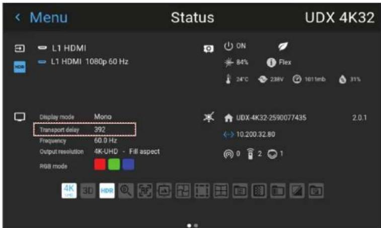
Image 8-57 Example of the Transport delay in the status menu
- Identify the projector with the longest delay.
- For each projector in the setup, select Installation → Warp in the main menu.
Image 8-58 Installation menu, Warp
- In the Warp menu, select Transport Delay.
Image 8-59 Warp menu, Transport delay
The Transport menu is displayed.
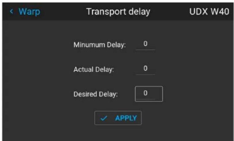
Image 8-60 Example of the Transport delay menu
- Enter the value either by the arrow keys (one step at a time) or directly by the numeric keys on the remote control.
- Click "Apply" to confirm the value.
- Repeat this process for every projector in the setup.
8.12 Blending & masking
About blending
Blending is used in multi channel installation to have a seamless transition between the channels. Image blending gives the appearance of a single view, thus achieving realistic immersion for the majority of wide screen applications.
The principle is that the light intensity in the blend zone from each projector will be adjusted individually, so that the rendering on the screen are perceived as from one projector.
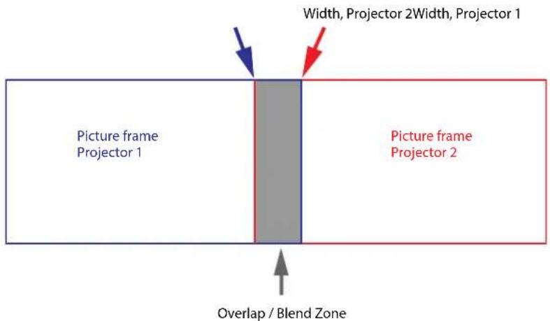
Image 8-61
From the start (mask) position, you can blend zone size per edge (left, top, right, bottom). For each edge there will be a drop-off curve for the blend zone.
Waiting period and blend maintenance period
The heating and cooling down of the lens in a projector startup and shutdown cycle can have a minor drifting effect on the blending and masking areas. Due to this, it is advised to wait 15–20 minutes after projector startup before performing blending and masking actions. This to make sure the drift on the blend region is as minimal as possible. For a similar reason, it is advised to wait 15–20 minutes after projector startup before starting any blending maintenance in your existing setup.

It is recommended to perform a blend maintenance after every 10–20 startup-shutdown cycles of the projector.
8.12.1 Basic blend
How to set up a basic blend zone?
- In the main menu, select Installation → Blend and Mask → Basic blend.
Image 8-62 Blend menu, Basic blend
The Basic blend menu is displayed.
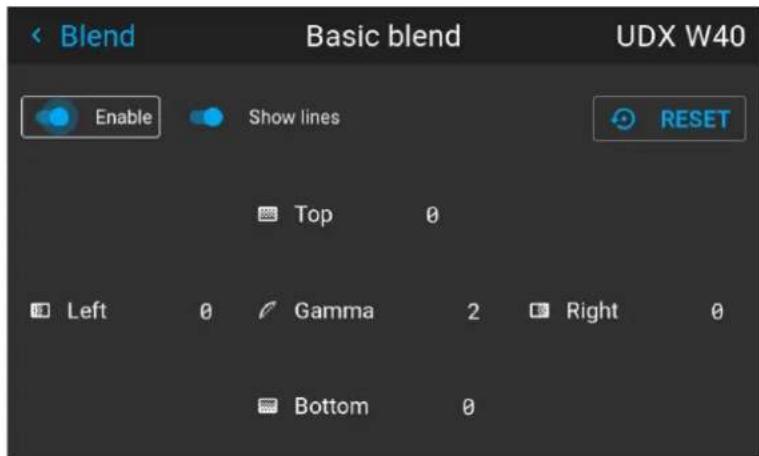
Image 8-63 Example of the basic blend menu
- To enable blending, put the Enable switch to the right. The color of the switch becomes blue when enabled.
- To project masking lines on the screen, put the Show lines switch to the right. The color of the switch becomes blue when enabled.
- Determine the start position of the blend area height and width to determine the dimension of the blend zone.
When the helping lines are activated, you will get a visual indication of the screen of the installed blending area.
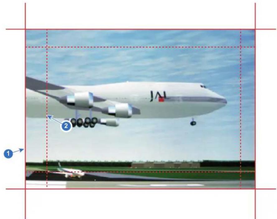
Image 8-64
1 Start position (mask)
2 Blending width
- Select one of the four starting positions values with the arrow keys and confirm.
- Use the arrow keys or remote digits to change the value of the blend zone and confirm.
- Repeat this process for all other desired sides.
- Continue by creating the blend mask. For more info, see "Blend & Blend mask", page 105.

Do not forget to disable the Show lines button after you achieved the desired blend zone.
8.12.2 Blend & Blend mask
About masking and blending width or height
Offset is used to clip the image on one or multiple sides (masking). This is used to hide parts of the picture that should not be shown on the screen. For example: if the source is a Windows PC, you can hide the menu bar using this method.
The larger the Mask value, the more the image is masked (by black bar) at the corresponding side. E.g. Top mask of 100 will blank the top 100 lines.
Height or width is used to create a blending zone with a smooth brightness drop off. This is used to compensate for the double brightness in overlap areas. The value is the size of the blended area in pixels.
How to set up basic blend zones?
- In the main menu, select Installation → Blend and Mask → Blend mask.
Image 8–65 Blend menu, Blend mask
The Blend mask menu is displayed.
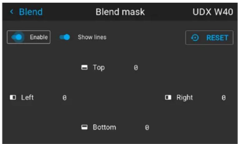
Image 8–66 Example of the blend mask menu
- To enable the blend mask, put the Enable slider to the right. The color of the slider becomes blue when enabled.
- To project masking lines on the screen, put the Show lines slider to the right. The color of the slider becomes blue when enabled.
- Determine the start position of the mask (1) for the masking height and width, together with the desired size of the mask (2) to determine the width of the masked area.
When the helping lines are activated, you will get a visual indication of the screen of the installed blending area.
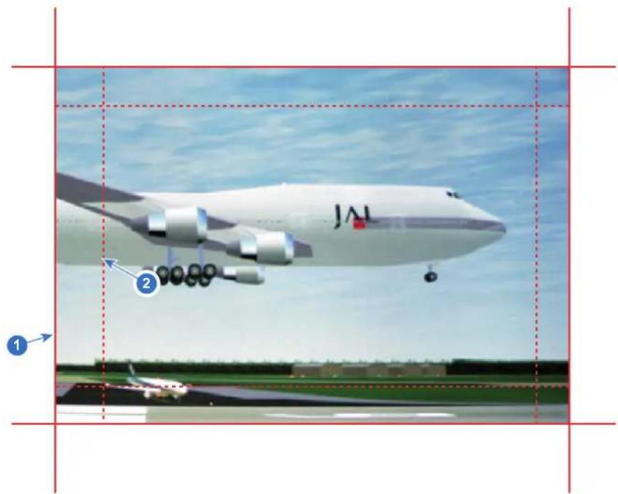
Image 8-67
1 Start position (mask)
2 Blending width
- Select one of the four starting positions values with the arrow keys and confirm.
- Use the arrow keys or remote digits to change the value of the mask and confirm.
- Repeat this process for all other desired sides.

Do not forget to disable the Show lines button after you achieved the desired blend zone.
Example of the use of blending
When projecting an image with 2 or more projectors, there is always an small overlap that should be corrected by using the blending function.

In order to obtain a satisfying result for the Blend function, the overlap / mask zone are recommended to be at least 10% of the picture width.
The basic principle is that the overlap setup in the source shall correspond with the mask width setup for the projector. That means that if the overlap zone for the source is set to 500 pixels, the width of the mask zone for the projector also must be set to 500 pixels.
First step is to align the image from the projectors as accurate as possible in a mechanical way, meaning without any optical corrections. At the same time, establish an overlap in the pictures between the two screens.
Then adjust the remaining irregularities by using the shift and warp features in the projectors to obtain the last fine tuning of the alignment.
Enable blending and activate Show lines.
First set the mask width for the right edge of the first projector. Enter a width value equal to the overlap area (width1).
Repeat for the left edge of the second projector.
Adjust the offset to cut the image on each side (masking).
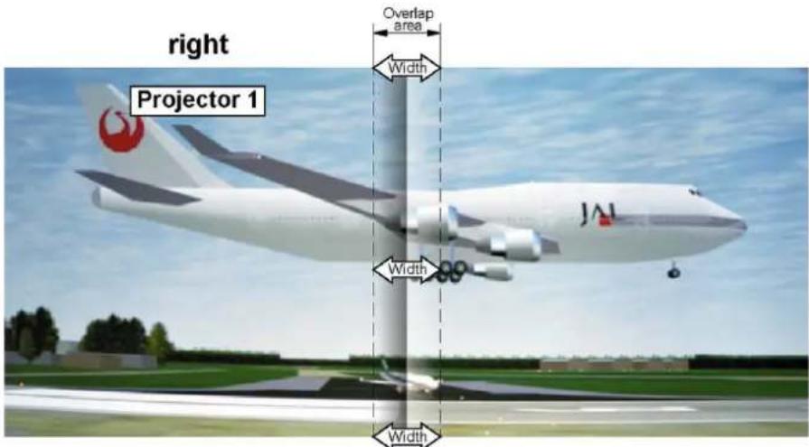
Image 8-68 Set up for projector 1
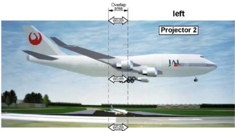
Image 8-69 Set up for projector 2
8.12.3 Blend Files
About custom Blend Files
Next to setting your specific Blending configuration in the GUI, you can also upload or download a custom Blend configuration file in png, jpg or tiff format to/from the projector. This is a timesaving option when multiple projectors need an identical blending configuration.
To upload or download Blend configuration files you can use Projector Toolset or upload/download the Blend configuration file in the format of an xml file. Alternatively, you can contact the "file endpoint" directly via the curl program or some other tool that supports http upload.
For more information on uploading/downloading blend files using the Projector Toolset, refer to the Projector Toolset user manual. For more information on uploading/downloading blend files using curl or other tools that supports HTTP upload, refer to the Pulse API reference guide.

When uploading custom blend files onto multiple projectors, make sure that the resolution of the blend file is supported by the projector you are uploading it to. A mismatch of projector resolution and blend mask resolution will result in a sub-optimal image performance. Verify the supported resolutions for the specific projector model via the Introspection tool [Introspection – image – resolution – alpha]. For more info on the introspection tool, consult the Pulse API reference guide.
How to activate an uploaded Blend configuration file?
- In the main menu, select Installation → Blend and Mask → Blend Files.
Image 8-70 Blend and mask menu, Blend files
The Blend Files menu is displayed.
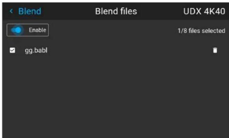
Image 8-71 Example of the blend files menu
- If any custom Blend files are available, select the desired file.
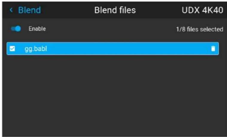
Image 8-72
- To enable the selected blend file, make sure the Enable slider is set to the right. The color of the slider becomes blue when enabled.
8.12.4 Basic black level adjustment
About adjusting the black level
The purpose of the black level adjustment is to align the black levels in the overlapped regions with the black levels in the other regions.
This is needed because the black levels will be brighter in the blend zones, since multiple projectors will project on the same screen area.
The size of the black level area is calculated automatically from the blend zones. This is done by using the start position and size of each edge of the blend and adding an additional size of 8 pixels to reduce the effect known as "sea of mirrors".
You can also specify the offsets manually by turning off the automatic calculation. The black level value is adjusted in a 16-bit resolution from 0 to 65535.
The following figure shows how this occurs in a side by side configuration without any correction of the black level.
Picture Left Picture RightBlend Zone
natural_image
Two vertical dark gray bars separated by a single vertical gray stripe (no text or symbols)Image 8-73
How to adjust the black level manually
- In the main menu, select Installation → Blend and Mask → Black Level.
Image 8-74 Blend and Mask menu, Black level
The Basic black level menu is displayed.
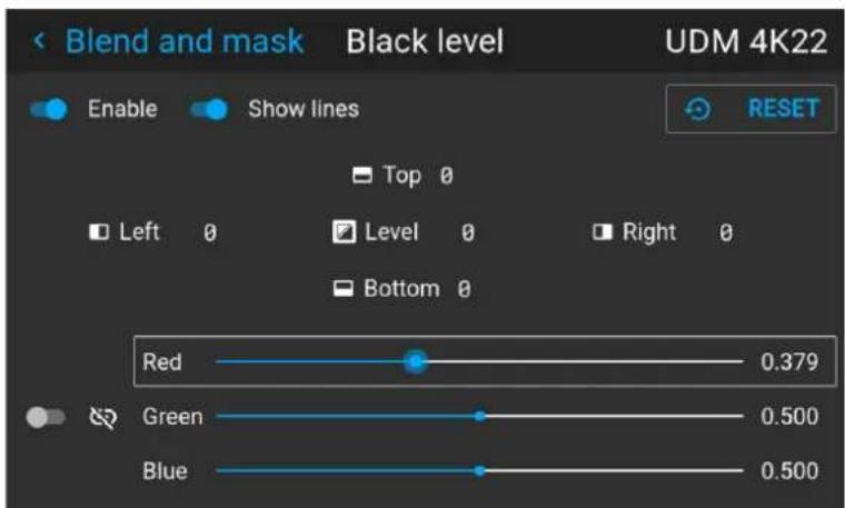
Image 8-75 Example of the default black level menu
- Enable the Black level slider. If you want a visual aid, enable the Show lines slider as well.
- Move the cursor to the side where the overlapped area occurs (Top, Left, Right or Bottom) and press enter.
- Adjust the level with the arrow keys and press enter when the desired black level zone is reached.
or
enter the black level value with the numeric keys in the remote control. - Move the cursor to Level, press enter and adjust this level until the black level equals the level in the blend zone.
This value can also be entered by the numeric keys on the remote control.
- Repeat the same procedure for any other projector connected to this projector, but on the opposite side.

Note: Do not forget to disable the Show lines button after you achieved the desired blend zone.
8.12.5 RGB gain adjustment
About RGB gain adjustment
The purpose of black level correction is to ensure a uniform black level in multi projector setups. Even when two projectors are of the same type, different projectors will output slightly different colors for black due to minor variations in their optical components. So if the projected image of the projectors overlap, there will be 3 different black levels: one for the zone where only the picture of the left projector (zone 1), one for the Blend zone (zone 2), and one for the zone where there is only the picture of the right projector (zone 3).
Picture Left Picture RightBlend Zone
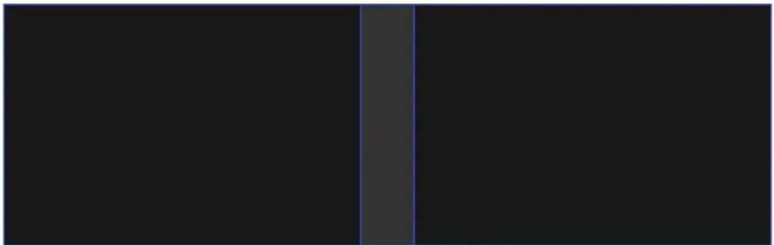
natural_image
Pure black rectangle with a vertical gray stripe on the left edge (no text or symbols)Image 8–76
The black levels for zone 1 and zone 3 are typically corrected by defining a black level mask, which is applied to the image of each projector. This system is already in place but the applied mask is monochrome.
Using the Basic Black Level menu, you can already specify the area of the mask and its contents. But by using the RGB Adjustment page, you can specify the multiplication factors (gains) for the Red, Green and Blue colors separately.
How to perform an RGB adjustment
- In the main menu, select Installation → Blend and Mask → Black Level.
Image 8–77 Blend and Mask menu, Black level
The Basic black level menu is displayed.
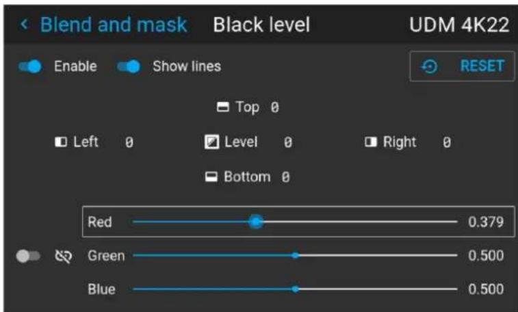
Image 8-78 Example of the default black level menu
- Select one of the three sliders on the bottom of the menu (Red, Green or Blue).
- Use the left and right arrow keys to modify the gain of the chosen color.
- Repeat for every slider until the desired result is achieved on screen.
8.12.6 Black Level Files
About custom Black Level Files
Next to setting your specific Black Level Adjustment in the GUI, you can also upload or download a custom Black Level adjustment file in png, jpeg or tiff format to/from the projector.
To upload or download Black Level adjustment files you can use Projector Toolset or upload/download the Black Level adjustment file in the format of an XML file. Alternatively, you can contact the "file endpoint" directly via the curl program or some other tool that supports http upload.
For more information on uploading/downloading Black Level files using the Projector Toolset, refer to the Projector Toolset user manual. For more information on uploading/downloading Black Level files using curl or other tools that supports HTTP upload, refer to the Pulse API Reference Guide.

When uploading custom black level files onto multiple projectors, make sure that the resolution of the file is supported by the projector you are uploading it to. A mismatch of projector resolution and black level file resolution will result in a sub-optimal image performance. Verify the supported resolutions for the specific projector model via the Introspection tool [Introspection – image – resolution – alpha]. For more info on the introspection tool, consult the Pulse API reference guide.
How to activate an uploaded Black Level adjustment file?
- In the main menu, select Installation → Blend and Mask → Black Level → Black Level Files.
Image 8-79 Blend and mask menu, Black level files
The Black Level Files menu is displayed.
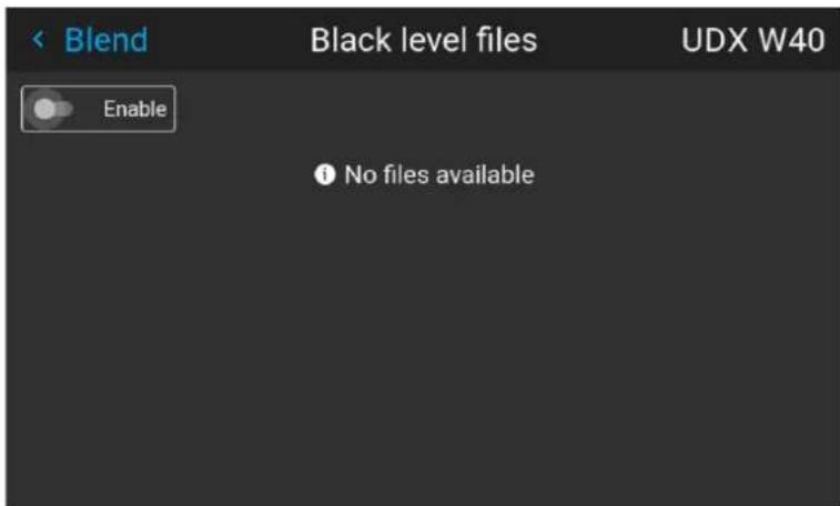
Image 8–80 Example of the black level files menu
- If any custom Black Level adjustment files are available, select the desired file.
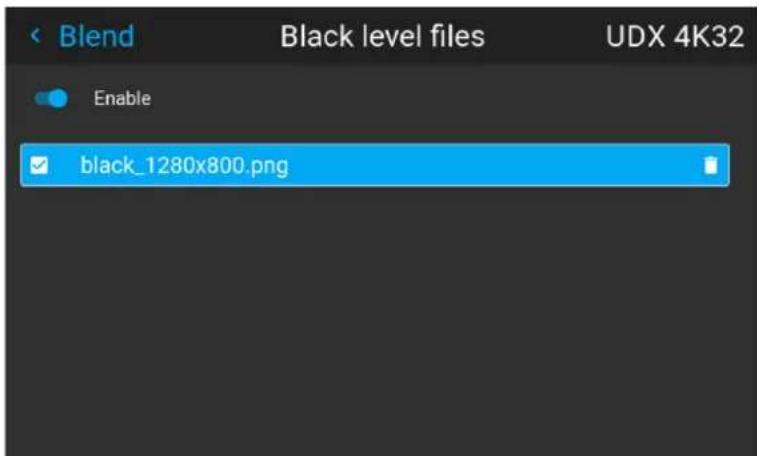
Image 8-81 Example of custom black level files selected
- Make sure the Enable slider is set to the right to activate the selected black level file
8.13 Illumination
What can be done?
Within a certain percentage, the light output of the light source can be reduced by reducing the power slider. Alternatively, you can enable CLO mode (Constant light output) for a constant light output over a longer period of time.

You can only change the power output when the shutter is opened.
About CLO mode
All light sources naturally decrease their intensity over time. In order to prevent a decreasing output in a multi-projector setup, you can activate CLO mode to make sure that the light output remains constant.
CLO mode will ensure that the projector regulates its illumination power to maintain the same level of output light during the lifetime of the light source. This requires that the light source power is not set to 100% from the start, but to a lower value. The lower this value is set, the longer the projector will be able to maintain the output level.

CLO can not be used when the light source is off, the shutter is closed or if the Dynamic Black feature is active (if available).
How to reduce the power
- In the main menu, select Installation → Illumination.
Image 8–82 Installation menu, illumination
The Illumination menu is displayed.
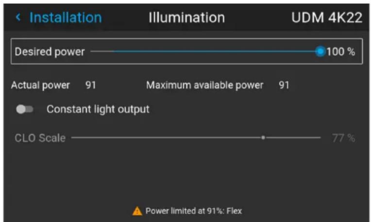
bar
| Category | Value | | -------------------- | ----- | | Desired power | 100% | | Actual power | 91% | | Maximum available power | 91% | | Constant light output | - | | CLO Scale | 77% |Image 8–83 Example of the Illumination menu
- Use the Slider to change the power value.
- Enable the Constant light output slider if you want to enable CLO mode.
- If CLO mode is active, you can use the CLO Scale slider to scale the light output.
8.14 3D projection
3D setup
The projector is capable of displaying 3D images and movies in active stereoscopic 3D.
Setup of a 3D installation requires an advanced understanding of 3D systems, both for the projector as well as for the system the signal source originates from. In a 3D setup it is crucial that the projected images are perfectly synchronized through the whole signal path, from the signal source to the picture viewed through the 3D goggles.
Regarding setting up the proper signal source, please refer to the user manual or online help for that graphic card. For example: when using NVIDIA Quadro cards, use the NVIDIA Control Panel to manage your 3D settings.
8.14.1 Active Stereo & Passive Stereo
What is Passive Stereo?
Passive Stereoscopic 3D (also known as “Passive Stereo”) is the standard method of creating the illusion of depth in an image, by means of stereopsis for binocular vision.
To present stereoscopic pictures, two images are projected superimposed onto the same screen through polarizing filters or presented on a display with polarized filters. For Digital Cinema, a silver screen is used so that polarization is preserved. On most passive displays every other row of pixels are polarized for one eye or the other. This method is also known as interlacing.
The viewer wears glasses which contain a pair of opposite polarizing filters. As each filter only passes light which is similarly polarized and blocks the opposite polarized light, each eye only sees one of the images, and the effect is achieved.
What is Active Stereo?
Field sequential 3D (also known as active 3D or “Active Stereo”) is a technique of displaying stereoscopic 3D images. It works by only presenting the image intended for the left eye while blocking the right eye's view, then presenting the right-eye image while blocking the left eye, and repeating this so rapidly that the interruptions do not interfere with the perceived fusion of the two images into a single 3D image.
This system setup uses liquid crystal shutter glasses (also known as active shutter glasses). Each eye's glass contains a liquid crystal layer which has the property of becoming opaque when voltage is applied, being otherwise transparent. The glasses are controlled by a timing signal that allows the glasses to alternately block one eye, and then the other, in synchronization with the refresh rate of the screen. The timing synchronization to the video equipment may be achieved via a wired signal or via wireless communication, this by using either an infrared or radio frequency (e.g. Bluetooth, DLP link) transmitter.
Projection method used
This projector can only show active 3D images, used in combination with a 3D emitter and active shutter glasses. While it is allowed to connect passive stereo source signals, the image processing of the projector will convert those signals to an active 3D compatible image.
The options on the projector software allow you to fine-tune the 3D settings accordingly to the specifications of the 3D emitter.

If a 3D emitter is used that radiates IR beams, the IR beams may interfere with the IR communication between projector and the RCU. If such interference occurs, connect the RCU to the projector using the remote cable. It is also advised to turn the IR receivers on the projector off to avoid the 3D emitter interference. To turn off the IR receivers, see "Pulse RCU, function of the on/off button", page 33.
8.14.2 Setup process 3D projection
How to setup 3D projection?
- Connect the proper source cables to the projector. For more info, see "Connection possibilities", page 114.
- Set up and connect your 3D emitter to the projector. For more info, refer to the user manual of your 3D emitter.
- Power on the projector completely.
- Select the correct stitched source Input in the Source menu. See "Displaying multiple sources: Stitched layouts", page 58.
- Depending on the chosen 3D emitter and chosen source, correct the 3D setup. For more info, see "3D Setup", page 115.
8.14.3 Connection possibilities

At this moment, the only inputs supporting 3D on the Pulse input boards are the DisplayPort inputs and HDMI input. More inputs may support 3D in a future release.
Connecting with the quad combo input card
There is only one way of projecting Active stereoscopic 3D with the Combo input card, using the following setup:
• Source: Active Stereo (sequential L/R)
- Layout mode: Standard layout (1x1 layout)
• Video Timing: 2560 x 1600 (WQXGA) @120 Hz
• Color depth: 30 bpp - Connector: DisplayPort 1.2 or HDMI
Connecting with the quad DP 1.2 Input card
You can use one of the following methods. The resulting image will always be an Active Stereo image.
| Source | Layout mode | Video Timing / cable | Fixed configuration? | Color depth |
| Active Stereo (sequential L/R) | Standard layout (1x1 layout) | 2560 x 1600 @120 Hz | 30 bpp | |
| Active Stereo (sequential L/R) | 4 Column mode (4x1 layout) | 960 x 2160 @120 Hz | 30 bpp | |
| Active Stereo (sequential L/R) | 4 Quadrant mode (2x2 layout) | 1920 x 1080 @120 Hz | 30 bpp | |
| Passive Stereo (separate L/R) | Standard layout (1x1 layout) | 3840 x 2160 @60 Hz | Cable 1: left eyeCable 2: right eye | 30 bpp |
| Passive Stereo (dual pipe L/R) | 2 Column mode (2x1 layout) | 1920 x 2160 @60 Hz | Cable 1: left eye, 30 bpp left columnCable 2: left eye, right columnCable 3: right eye, left columnCable 4: right eye, right column | 30 bpp |
8.14.4 3D Setup
Why change the 3D setup?
While Barco can provide a 3D emitter and active shutter glasses as options to this projector, you are also free to use a 3D emitter and active shutter glasses of your own choice. Since glasses and emitter can have various specifications compared to the ones Barco can provide, the 3D setup menu allows you to configure the output image to the specifications of your glasses and emitter. The following can be configured:
- Swap Eyes: You can choose to invert the stereo Sync output signal (depending on the chosen 3D emitter and glasses).
- Swap frame pair: This setting allows you to correct the frame doubling sequence. If the frame rate of the projected moving 3D content doesn't look smooth, this option may help improve this.
- Dark time: You can select how much dark time the projected image will have between frames. You can choose one of the options between 1000 s and 2500 s.
- Output mode: Choose the desired output mode. For more details, see further.
- Sync Delay: You can increase or decrease the sync delay. The scale goes from -10 000 s to +10 000 s with a step of 100 s .
Choosing the desired output mode
The following output modes are available:
- AutoStereo: Automatic mode (2D input = 2D output, 3D input = Active Stereo output).
- Mono: Forces all source signals to 2D output.
• ActiveStereo: Forces all source signals to Active Stereoscopic 3D.
Use the following table as an indicator of what display mode you require.
Source signal
AutoStereo Mono ActiveStereo
2D Source Output is a 2D image Output is a 2D image Output is in Active Stereo
Active Stereo source Output is in Active Stereo Output is a 2D image Output is in Active Stereo
Passive Stereo source Output is in Active Stereo Output is a 2D image Output is in Active Stereo

When a different Display Mode is chosen compared to the source signal (e.g. Active Stereo source with Mono output), advanced image processing will make sure you a desirable image will be displayed.

If a 3D emitter is used that radiates infrared beams (IR beams), the IR beams may interfere with the IR communication between projector and the RCU. If such interference occurs, connect the RCU to the projector using the remote cable. It is also advised to turn the IR receivers on the projector off to avoid the 3D emitter interference. To turn off the IR receivers, see "Pulse RCU, function of the on/off button", page 33.
How to adjust the projector to the 3D emitter?
- In the main menu, select Installation → 3D Setup.
Image 8–84 Installation menu, 3D setup
The 3D setup menu is displayed.
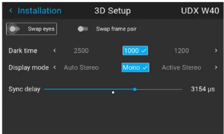
Image 8-85 Example of the 3D setup menu on a UDX
- If it is necessary to invert the stereo sync output, enable the Swap eyes option.
- If the projected moving 3D content doesn't look smooth enough, enable the Swap frame pair option to help improve this.
- Select the desired the stereo Dark Time.
- Select the desired Display mode.
- Use the slider to set the desired stereo Sync delay.
GUI – Projector profiles
9
9.1 Saving the current projector settings in a profile 118
9.2 Assigning a created projector profile to a preset 120
9.3 Deleting a projector profile....121
About projector profiles
The profile function makes it possible to store different profiles / projector setups for different use cases, and quickly recall them when needed. This means that it is not necessary to enter a lot of different menus to adjust the projector setup for specific recurring use cases. Due to the limited nature of this function and to avoid terminology confusion with more complex macro's, these are not called “macro's”, but “profiles”.
A few examples of different user cases are:
- Building temporary gaming setups in bright auditorium-level environment, versus a darker “gaming room” or “cave”.
- Playing content from an old DVD versus playing the latest release from an HDR-coded Blu-Ray.
- A rental projector that can be rented out for business presentations, concerts and other events that have different but recurring forms of content.
9.1 Saving the current projector settings in a profile
Which settings can be saved to a profile?
| Profile domain name | Settings saved |
| Illumination | · Illumination power for each source· Light sensor enabled / disabled· Light sensor set point |
| Source Active source selection & EDID | |
| Image | · Contrast· Brightness· Saturation· Sharpness· Gamma· Used gamma type· Digital zoom (width / height / factor + enabled/disabled)· Digital shift (x / y + enabled / disabled)· Output resolution |
| Display (3D settings) | · 3D Display mode used· Swap eyes on / off· Swap frame pair on / off· Dark time and sync delay values |
| RealcolorTM | · Brilliant Color mode (if available)· P7 desired values· P7 measured values |
| Warp | · Warp status enabled / disabled· Screen size· Warp file selected (if available)· Transport delayNote: Bow and 4 corners warp cannot be saved. |
| Blend | · Blend mask enabled / disabled· All Masks (top / bottom / left / right) and heights (top / bottom / left / right)· Blend files enabled / disabled (if available)· Blend file selected (if available) |
| Black level | · Black level file enabled / disabled· Black Level file selected (if available)· Basic black level enabled / disabled· Black level settings (top / bottom / left / right)· RGB gain values (Red, Green and Blue values) |
| PQ (HDR) | · Screen luminance (unit and value)· HDR Boost value· DynaBlack mode |
| Installation | · Lens parameters (lens zoom, focus, shift and iris (if available))· Orientation (mounting & projection)· Scaling mode· Position of motorized frame (if used).· Shutter status (open or closed). |
| Cooling4 | Selected Cooling mode |
How to save the current projector settings?
- In the main menu, select Profiles → Edit.
Image 9-1 Profiles menu, edit
The Profile edit menu is displayed.
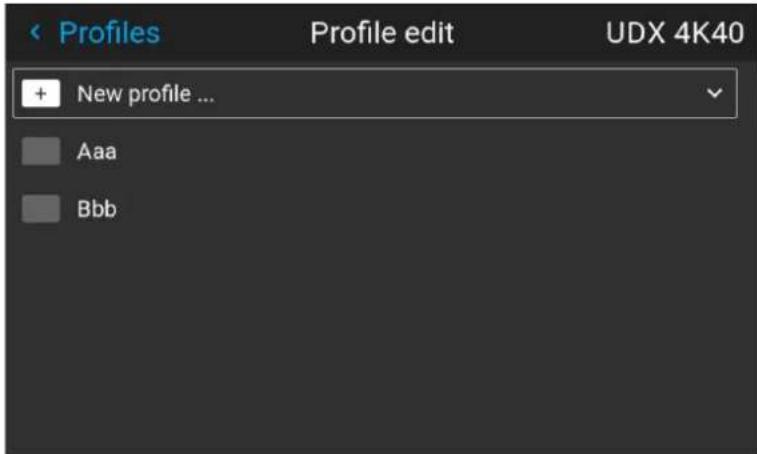
Image 9-2 Profile edit menu
- Use the arrow keys to select New Profile... and confirm. The New Profile pane is expanded and fully displayed.
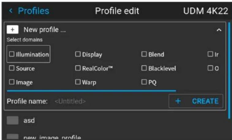
Image 9-3 Example of the new profile pane
- Use the arrow keys and the okay key to select any of the settings you wish to save in this macro.
- Select the field next to Profile Name and confirm with the Okay key to display a keyboard.
- Use the keyboard to enter a valid macro name. Confirm with the enter key once completed.
- Select CREATE and confirm to save the current profile settings.
9.2 Assigning a created projector profile to a preset

This procedure assumes you have created at least one projector profile. For more info on saving projector settings to a profile, see "Saving the current projector settings in a profile", page 118.
How to assign a projector profile to a preset
- In the main menu, select Profiles → Edit.
Image 9-4 Profiles menu, edit
The edit menu is displayed.
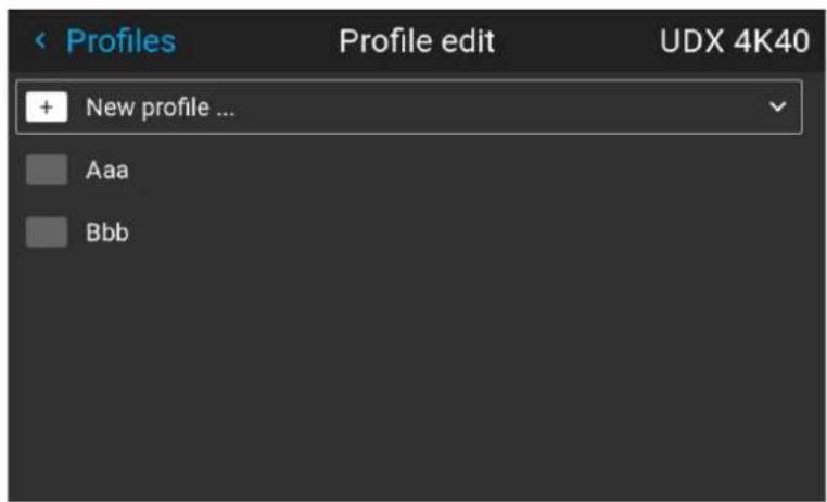
Image 9-5 Profile edit menu
- Select the desired projector profile from the list and confirm.
The profile pane will expand.
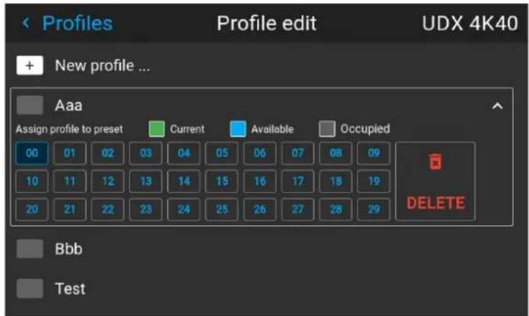
Image 9-6 Example of a projector profile with available preset slots
- Use the arrow keys to select a preset slot and confirm with the okay key.
The preset slot is now shown next to the profile name.
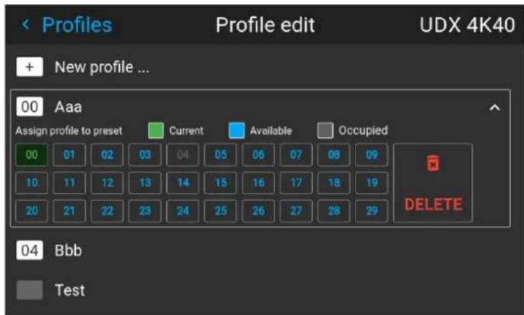
Image 9-7 Example of projector profiles allocated to preset slots (here slot 00 and 04)
9.3 Deleting a projector profile
How to delete a profile
- In the main menu, select Profiles → Edit.
Image 9-8 Profiles menu, edit
The edit menu is displayed.
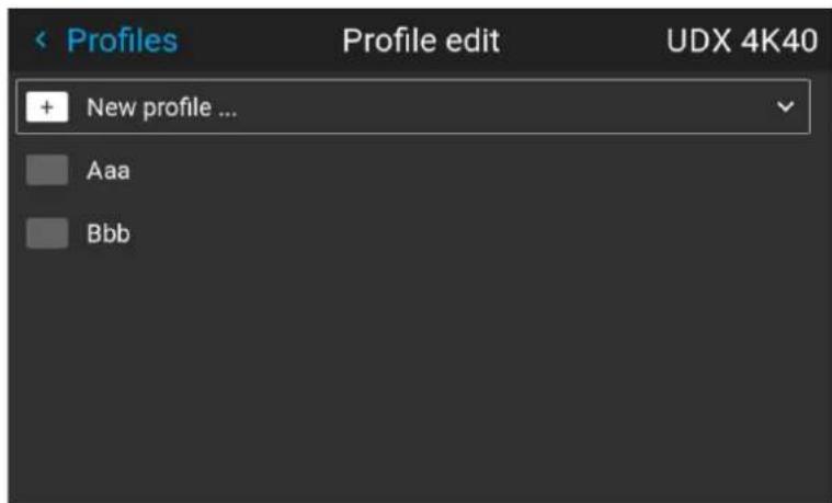
Image 9-9 Profile edit menu
- Select the undesired projector profile and confirm to expand it.
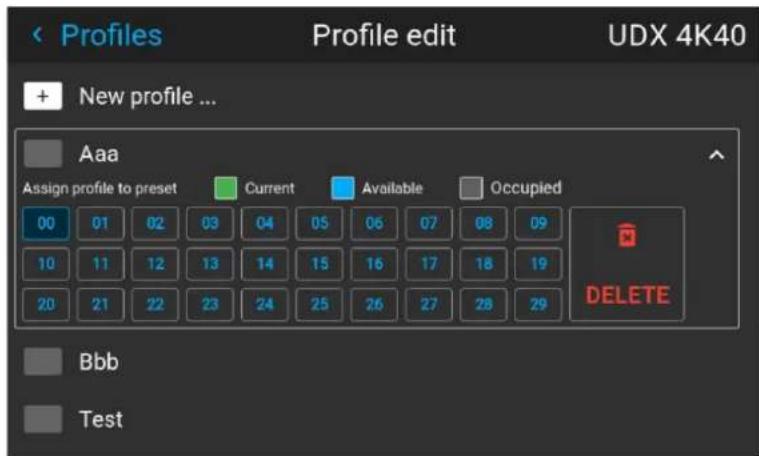
Image 9–10 Example of a projector profile with available preset slots
- Use the arrow keys to select Delete and confirm. confirm the delete action.
GUI - System Settings
10
10.1 Remote control.... 124
10.2 Host name - custom projector name setup.... 126
10.3 Communication, LAN setup....127
10.4 DMX....135
10.5 Front XLR output voltage control.... 137
10.6 GSM configuration....138
10.7 Changing the User Interface language 139
10.8 Themes 139
10.9 Units (measurement) system setup.... 140
10.10 Controlling the backlight of the LCD Display.... 141
10.11 Date and time setup - manually....141
10.12 Date and time setup - automatically.... 142
10.13 Power saving settings – Standby mode 144
10.14 Lens features 145
10.15 Factory reset....146
10.16 Lens Calibration 149
10.17 Flex brightness.... 151
10.18 Rigging frame Calibration.... 152
10.19 Electronic Convergence 153
10.20 Setting up the external cooler on a UDX 154
10.21 Capture mode 155
10.22 Login to advanced settings.... 156
10.23 List of open source licenses.... 156
10.1 Remote control
10.1.1 Broadcast address
About broadcast address
Broadcast address is a common address that can be set on the projector. That can be "0" or "1". The default broadcast address is '0'.
Any command coming from an RCU programmed with that common address will be executed.
How to the broadcast address
- In the main menu, select Settings → Communication → Remote control.
Image 10-1 Communication menu, Remote Control
The Remote control menu is displayed.
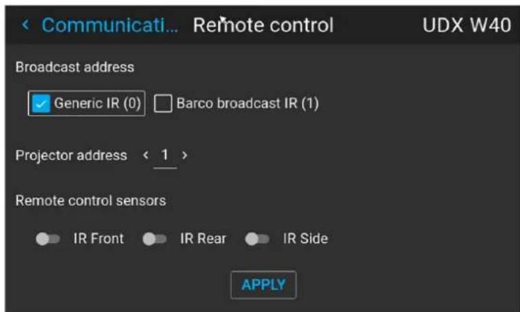
Image 10-2 Example of the Remote control menu
- To change the broadcast address select the radio button of your choice.
The following choices are possible:
-
Generic IR (address 0)
• Barco broadcast IR (address 1) -
Select APPLY and click OK to apply the changes.
10.1.2 Projector address
About individual projector address
As more than one projector can be installed in a room, each projector should be separately addressable with an RCU or with a computer using serial communication. Therefore each projector has its own address. The factory default individual projector address is '0'.
When the address is set, the projector can be controlled with the RCU. Only addresses between 0 and 31 are supported for the RCU.
Next to an individual projector address, each projector has also a broadcast address for group control.
How to change
- In the main menu, select Settings → Communication → IR control.
Image 10-3 Communication menu, Remote Control
The Remote control menu is displayed.
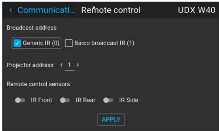
Image 10-4 Example of the Remote control menu
-
Select the current projector address and enter a new address.
-
Select APPLY and click OK to apply the changes.
From now on the projector will only listen to this new address and to its broadcast address.
10.1.3 IR sensors
What can be done?
Each IR sensor can be individually disabled or enabled.
When all sensors are turned off, the projector will no longer respond to signals from the remote control. To re-enable the sensors, use the menu keypad on the projector.
How to disable
- In the main menu, select Settings → Communication → IR Control.
Image 10-5 Communication menu, Remote Control
The IR control menu is displayed.
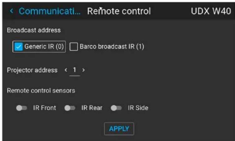
Image 10-6 Example of the IR control menu
- To disable an IR sensor, select the slider and drag to the left.
A blue slider means an active IR sensor.
A gray slider means an inactive IR sensor.
- Select APPLY and click OK to apply the changes.
10.2 Host name - custom projector name setup
What can be done?
The default host name of the projector is the projector type along with the serial number of your projector (e.g. "UDX-4K40-0123456789").
You can change this name to make it easier to spot in a network with multiple devices or projectors
How to set a different Host name
- In the main menu, select Settings → Communication → Host name.
Image 10-7 Communication menu, Host name
The Host name menu is displayed.
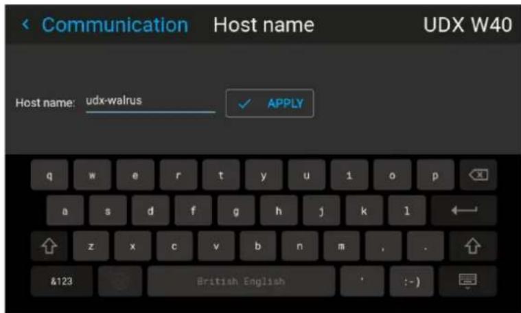
Image 10-8 Example of the host name menu
- Press confirm to edit the Host name field.
- Use the digital keyboard to change the Host name to the desired custom name.
- Press the OK key, or press the enter icon to confirm the typed name. Click Apply to update the host name.
10.3 Communication, LAN setup
About a network connection
A network connection can be made via a wired connection or via the optional wireless unit.
10.3.1 Introduction to a Network connection

DHCP
Dynamic host configuration protocol. DHCP is a communications protocol that lets network administrators manage centrally and automate the assignment of IP addresses in an organization's network. Using the Internet Protocol, each machine that can connect to the Internet needs a unique IP address. When an organization sets up its computer users with a connection to the Internet, an IP address must be assigned to each machine. Without DHCP, the IP address must be entered manually at each computer and, if computers move to another location in another part of the network, a new IP address must be entered. DHCP lets a network administrator supervise and distribute IP addresses from a central point and automatically sends a new IP address when a computer is plugged into a different place in the network.

IP
Internet Protocol. The network layer of TCP/IP. Required for communication with the internet.

Subnet mask
A number that is used to identify a subnetwork so that IP addresses can be shared on a local area network.

Default Gateway
A router that serves as an entry point into and exit point out of a network. For example, a local network (LAN) may need a gateway to connect it to a wide area network (WAN) or to the Internet.

MAC address
Media Access Control address. Unique hardware number, used in combination with the IP-address to connect to the network (LAN or WAN).
What should be set up for an Ethernet address?
Two ways can be used to assign an address:
- use the Automatic setting so that an automatic address will be assigned.
- Assign manually an IP address, Net-mask (subnet-mask), (default) gateway address.
- Set the IP-Address field to the desired value. This must NOT be 0.0.0.0 for static IP-Address assignment. The IP address identifies a projector's location on the network in the same way a street address identifies a house on a city block. Just as a street address must identify a unique residence, an IP address must be globally unique and have a uniform format.
- Set the Subnet-Mask as appropriate for the local subnet.
- Set the Default-Gateway to the IP-Address of the local router (MUST be on the local subnet!) on the same network as this projector that is used to forward traffic to destinations beyond the local network. This must not be 0.0.0.0. If there is no router on the projector's local subnet then just set this field to an IP-Address on the subnet.
10.3.2 Wired IP address set up
How to automatically set up the IP address
- In the main menu, select Settings → Communication → LAN.
Image 10–9 Communication menu, LAN
The LAN menu is displayed.
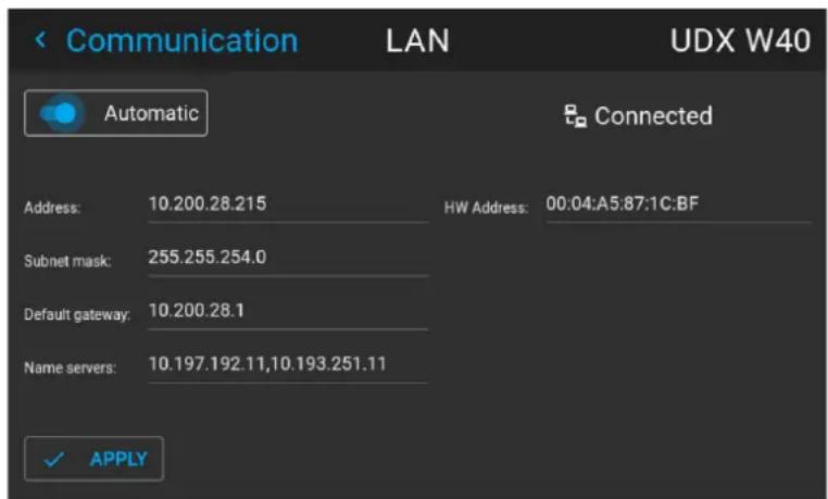
Image 10–10 Example of the LAN menu
- To enable Automatic, make sure the Automatic slider is set to the right. The color of the slider will be blue.
An IP address will be automatically assigned if it can make a connection to the network..
When connected, it is indicated with the connection symbol and the indication Connected.
- Select APPLY and confirm.
How to manually set up the IP address
- In the main menu, select Settings → Communication → LAN.
Image 10-11 Communication menu, LAN
The LAN menu is displayed
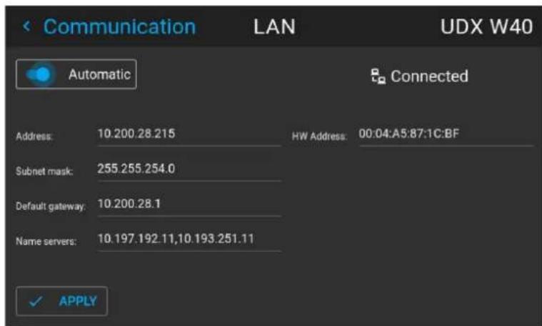
Image 10-12 Example of the LAN menu
- Disable the Automatic slider. The slider becomes gray.
- Use the arrow keys to select Address and press OK button to activate the input box.
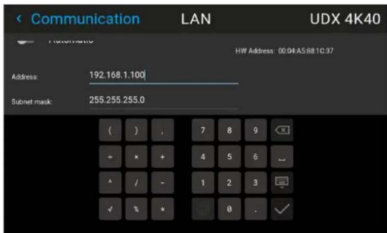
Image 10-13 Example of entering the IP address
- Use the arrow keys and enter key to enter in the IP address.

Note: Digits can be entered with the digit keys on the remote control or the local keypad. When a digit is entered in that way, the next character will be selected automatically.
- Once filled in, select the √ symbol and confirm.
- Repeat steps 4 and 5 for the Subnet mask and Default Gateway.
- Select APPLY and click OK to confirm all changes.
When the connection is established, it is indicated with the connection symbol and the indication Connected.
10.3.3 Wireless IP address set up
When can the wireless IP address be used?
When the optional WiFi module has been installed on the projector, you can configure the projector in such a way it can access the network via WiFi instead of a LAN cable.
For more information on how to install the WiFi module, please refer to the installation manual.
How to connect to a wireless network?
- In the main menu, select Settings → Communication → WiFi.
Image 10–14 Communication menu, WiFi
The WiFi menu is displayed.
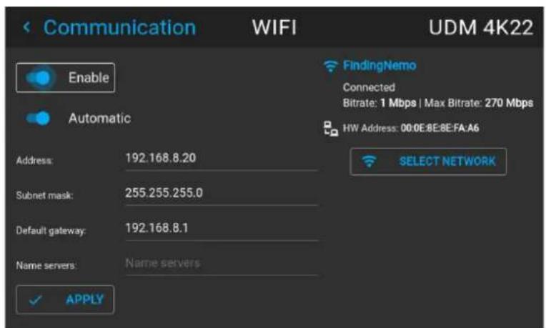
Image 10-15 Example of the WiFi menu
- Make sure the Enable slider is set to the right to enable the WiFi module. The color of the slider becomes blue.
- Make sure the Automatic slider is set to the right to automatically assign an IP address.
- Use the Select Network button to select the desired network from the available list.
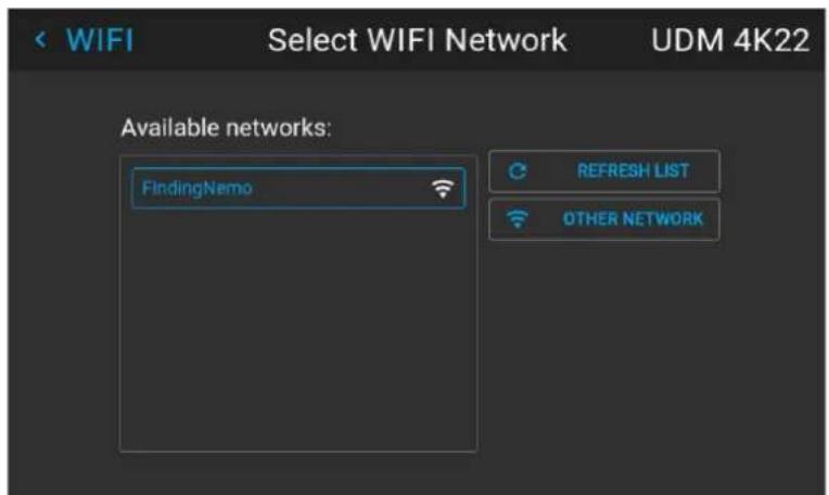
Image 10–16 Example of the available networks list.

Tip: If the desired wireless network is not in the list or hidden by default, select Other network. A form will pop up, allowing you to fill in the details of the network.
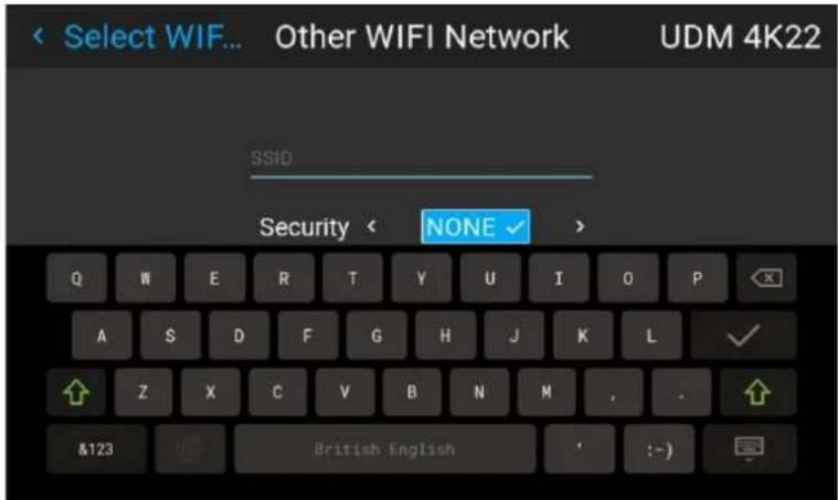
Image 10–17 Example of the entry form to search for other wireless networks
- If required by the chosen wireless network fill in the user name, password and confirm.

Tip: If you already connected to this network in the past using this projector, the software will remember the user name and password, ensuring you do not have to fill this in again.
-
Press Connect to connect to the selected network.
-
If required by the chosen wireless network, fill in the user name and password and confirm.
An automatic IP address is assigned.
When connected to this network, it is indicated in the upper right corner of the menu with the term "connected".
How to manually set up the IP address
- In the main menu, select Settings → Communication → WiFi.
Image 10-18 Communication menu, WiFi
The WiFi menu is displayed.
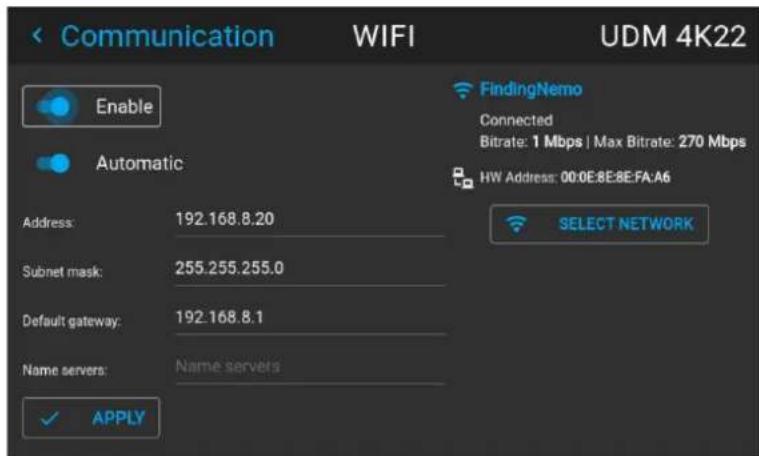
Image 10-19 Example of the WiFi menu
- Make sure the Enable slider is set to the right to enable the WiFi module. The color of the slider becomes blue.
- Disable the Automatic slider by setting it to the left. The switch becomes gray.
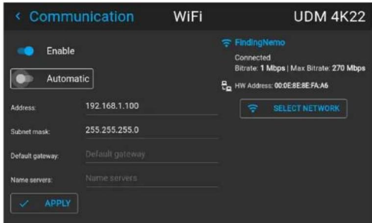
Image 10-20
- Use the arrow keys to select Address and press OK button to activate the input box.
- Use the arrow keys and enter key to enter in the IP address.

Note: Digits can be entered with the digit keys on the remote control or the local keypad. When a digit is entered in that way, the next character will be selected automatically.
- Once filled in, select the √ symbol and confirm.
- Repeat steps 4 and 5 for the Subnet mask and Default Gateway.
- Select APPLY and click OK to confirm all changes.
- Select the Select Network button to select the desired wireless network from the list.
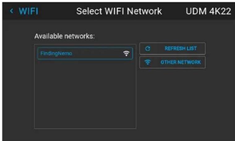
Image 10-21 Example of the available networks list.
- Press Connect to connect to the selected network.
- If required by the chosen wireless network, fill in the username and password and confirm.
When connected to this network, it is indicated in the upper right corner of the menu with the term "connected".
10.3.4 LAN over HDBaseMIP address set up

LAN over HDBaseT is only supported on HDBaseT input 1 on the Pulse Quad Combo Input board Mk II.
About LAN over HDBaseT
When a LAN cable is mounted in HDBaseInput 1, the HDBase™ menu will appear in the Settings menu. Using the menu, you can assign a custom IP address, or leave the automatic IP address setup.

Keep into account that the HDBase Network will be unavailable if the projector is in Standby mode or ECO mode (whichever is applicable to your projector). If you want to use this connector as your main network connection, it is thus advised to disable the standby or ECO mode. For more info, see power settings.
How to automatically set up the IP address
- In the main menu, select Settings → Communication → HDBaseT ^TM .
Image 10-22 Communication menu, HDBase
The HDBase™ menu is displayed.
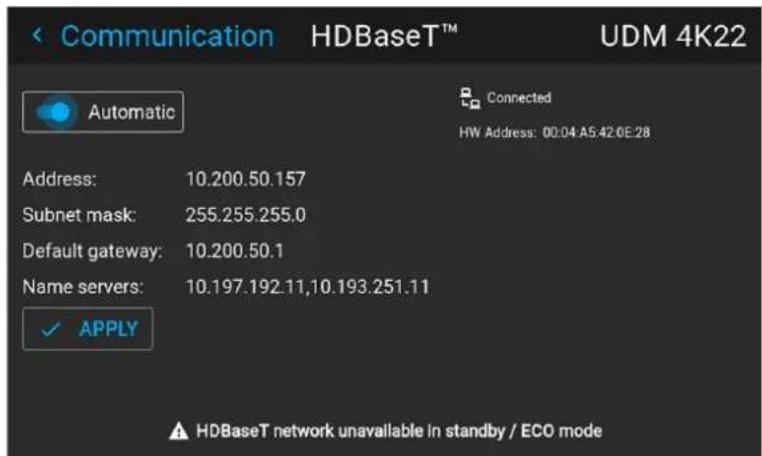
Image 10-23 Example of the HDBaseTmenu
- To enable Automatic, make sure the Automatic slider is set to the right. The color of the slider will be blue. An IP address will be automatically assigned if it can make a connection to the network.. When connected, it is indicated with the connection symbol and the indication Connected.
- Select APPLY and confirm.
How to manually set up the IP address
- In the main menu, select Settings → Communication → HDBaseT ^TM .
Image 10-24 Communication menu, HDBase™
The HDBase™ menu is displayed.
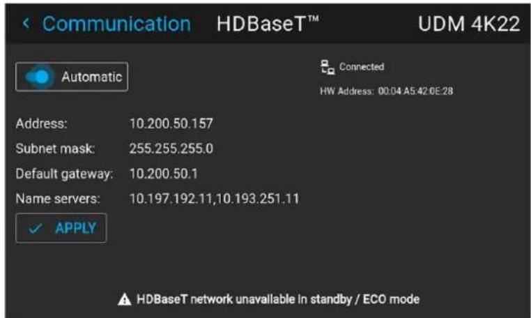
Image 10-25 Example of the HDBaseTmenu
- Disable the Automatic slider. The slider becomes gray.
- Use the arrow keys to select Address and press OK button to activate the input box.
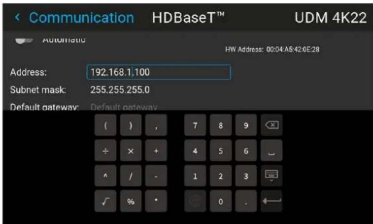
Image 10-26 Example of entering the IP address
- Use the arrow keys and enter key to enter in the IP address.

Note: Digits can be entered with the digit keys on the remote control or the local keypad. When a digit is entered in that way, the next character will be selected automatically.
- Once filled in, select the Enter symbol and confirm.
- Repeat steps 4 and 5 for the Subnet mask and Default Gateway.
- Select APPLY and click OK to confirm all changes.
When the connection is established, it is indicated with the connection symbol and the indication Connected.
10.4 DMX
About the ways to control the projector via DMX
DMX signals can be connected to the DMX In port on the communicator interface when using a standard DMX cable equipped with XLR connector. The DMX out can be used to create a chain of DMX devices. One universe can control up to 512 channels.
If you are using a DMX console and other automated lighting products compatible with Art-Net, the Ethernet network can serve as the link for DMX control. All DMX controls can be sent over the Ethernet cable. Multiple universes are possible.
For a full list of all DMX channels, values and possible actions, see "DMX chart", page 209.
About the DMX menu
| DMX Feature | What can be done? |
| DMX Mode T | Two different modes for DMX are available.Basic: A basic configuration where 2 channels are implemented.Extended: A full configuration, spread over 14 channels.For the full mapping of each used channel, refer to the DMX chart in the appendices. See “DMX chart”, page 209. |
| Start Channel | Before a projector can execute DMX commands, a unique address (named DMX address or Starting channel) should be given to the projector.This address can vary from 1 to 512. |
| DMX Monitor | If a DMX device is connected, the settings per channel can be displayed via theMonitorbutton. |
| Reset for Max intensity | You can change the Shutter and intensity via DMX Channel 1 (both in Basic and Extended mode).If no DMX signals are available, you can reset the intensity value to its default (maximum) value of 255 using the Max Intensity button. |
| Auto power down | The projector can be forced to shut down after a certain time-out period if no DMX signals are available.Note: Value is set in minutes. |
| DMX Art-Net | DMX can be sent via the Ethernet connector to the projector instead of the classic DMX connector. This function can be enabled or disabled. Art-Net is generally used when more than 512 addresses are used in your setup. |
| DMX Art-Net Universe | Note: DMX Art-Net Universe can only be used when Art-Net DMX is enabled.If Art-Net is enabled, you can specify which DMX universe this projector belongs to. |
| Front XLR connector | If available on your projector, the power of the XLR connector on the front side of the projector can be enabled and set to a desired value.Note: If no front XLR connector is available on your projector, this option remains hidden. |
How to set up DMX?
- In the main menu, select System Settings → Communication → DMX.
Image 10–27 Communication menu, DMX
The DMX menu is displayed.
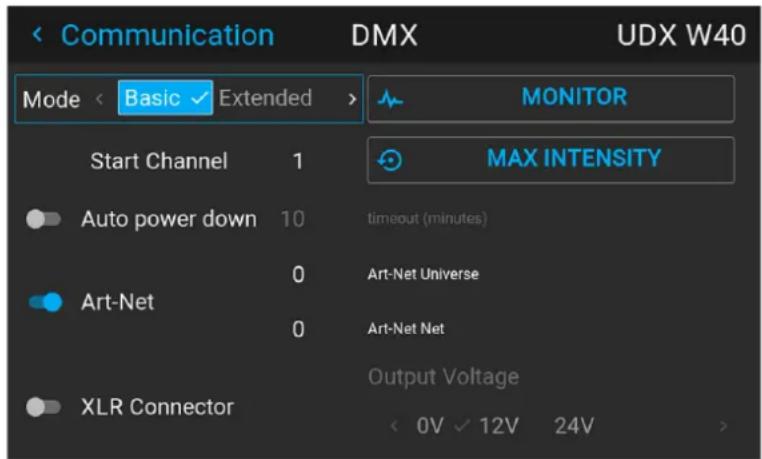
Image 10–28 Example of the DMX menu
- Choose the desired DMX mode.
- Choose the desired starting channel.
- Choose whether or not you want the Auto power-down feature to be enabled. If enabled, determine the time-out.
- If required, enable Art-Net. If enabled, determine the desired Art-Net Universe and Art-Net channel.
- If a front XLR connector is available on your projector, you can enable the output voltage on this connector.
10.5 Front XLR output voltage control
What can be done?
The output voltage on the front XLR connector can be enabled or disabled. If enabled, the output voltage level can be set to 0 V, 12 V or 24 V.
The output voltage will depend on the application or peripheral used. For example, the optional external mechanical shutter requires 12 V. The motorized rigging frame on the other end requires 24 V.
Location of the XLR connector

Image 10-29 Location of the XLR connector on the UDX
How to enable or disable?
- In the main menu, select System Settings → Communication → DMX.
Image 10–30 Communication menu, DMX
The DMX menu is displayed.
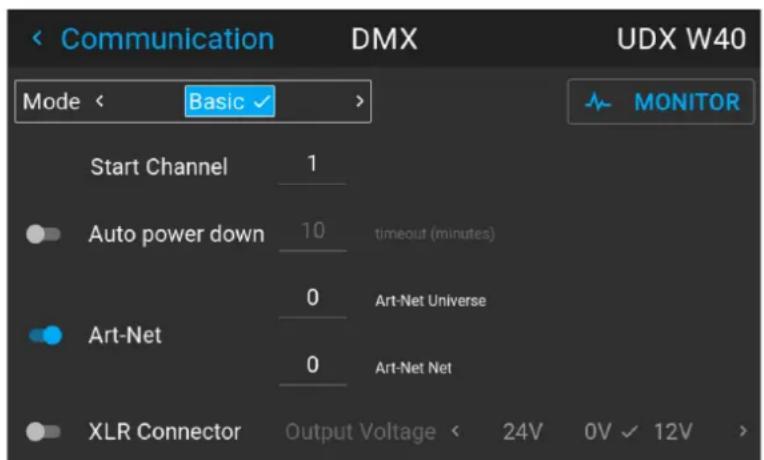
Image 10-31 Example of the DMX menu
- On the bottom of the DMX menu, Enable the XLR connector slider.
- Select the desired Output Voltage.
10.6 GSM configuration

Only possible when a GSM module with SIM card is installed in the projector.
When to use the GSM menu
The GSM menu by itself does not have any functionality. The main purpose of this menu is to read out the necessary data from the SIM card in the GSM module.
You may require this information when using specific connectivity functions (e.g. configuring the Projector Management Suite in a mobile-only setup).
About the SIM card PIN code
To configure the projector software with the installed SIM card for the first time, a correct PIN code (4 digits) must be entered.

As the PIN code cannot be checked with the one on the SIM card, ensure to enter the correct PIN code.

When your SIM card is blocked, you have to remove the SIM card from the GSM module and to insert the SIM card in a mobile phone so that you can enter the PUK code to unblock the SIM card.
How to activate
- In the main menu, select Settings → Communication → GSM.
Image 10–32 Communication menu, GSM
At first use, the GSM pin code input menu is displayed. If a correct pin code has been entered in the past, it will not be necessary to enter the pin code again and you can skip the next step.
- Enter the 4 digits of the PIN code and confirm.
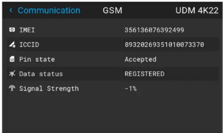
Image 10–33 Example of the GSM menu once the pin code has been applied
10.7 Changing the User Interface language
How to change the language of the user interface
- In the main menu, select Settings → User interface → Language.

Image 10-34 Interface
The Language menu is displayed.
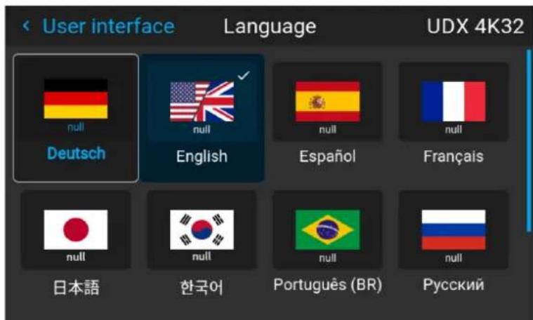
Image 10-35 Example of the Language menu
-
Select the desired language. You can choose between the following:
-
German (DE)
- English (EN)
- Spanish (ES)
- French (FR)
- Japanese (JA)
- Korean (KO)
- Portuguese (PT-BR)
- Russian (RU)
- Chinese (ZH)
10.8 Themes
About Themes
Themes are used to apply a predefined functionality to the OSD display. There are two options: light or dark (default).

While the default theme is dark, all images in this manual are taken while using the light theme.
How to select a different interface theme
- In the main menu, select Settings → User interface → Themes.
Image 10-36 Settings menu, themes
- In the themes menu, select the desired Theme.
You can choose one of the following: Light, or Dark.
10.9 Units (measurement) system setup
About the measurement systems
You can use this menu to change the default measurement systems. By default the metric system is used. But you can choose between the following:
• Temperature: °C or °F
• Distance: meter, centimeter, feet or inch.
How to set a different metric system
- In the main menu, select Settings → User interface → Units.
Image 10-37 Settings menu, units
The Units menu is displayed.
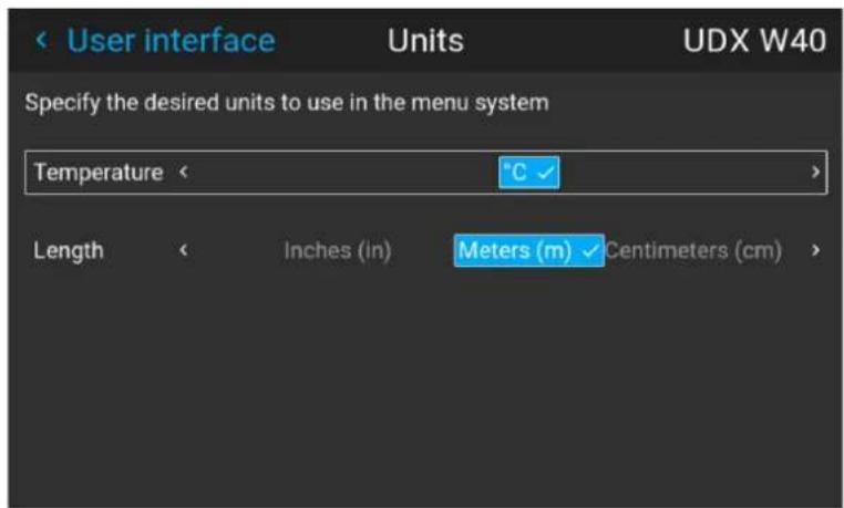
Image 10–38 Example of the Units menu
- Select the desired Temperature unit and Length unit and confirm.
10.10 Controlling the backlight of the LCD Display
What lighting can be controlled?
You can choose how quickly the backlight of the LCD turns off. You can select one of the default values, or enter a custom value.
Stealth Mode
Alternatively, you can turn on Stealth Mode instead. By activating this mode, the backlight of the LCD, the backlight of all the buttons of the keypad and the indication LEDs for the LAN and HDbaseT inputs will be disabled.
Stealth Mode is enabled and disabled by pressing the OSD button on the remote control for 3 seconds.
How to set the backlight
- In the main menu, Settings → User interface → Backlight.
Image 10–39 Settings menu, backlight
The Backlight menu will be displayed.
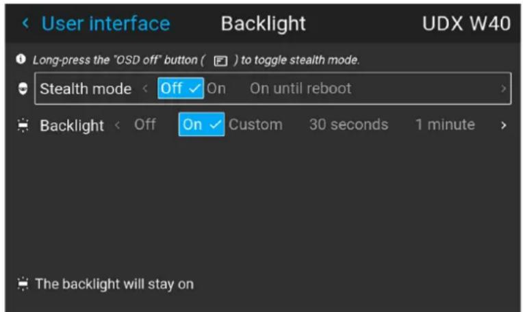
Image 10–40 Example of the backlight menu
- Choose the desired setting for the backlights. Select one of the predetermined options, or a custom value.
10.11 Date and time setup - manually
About date and time
The date and time setting can be set manually or automatically via an NTP server based on region and city location.

Date is displayed by default as: day / month / year.
Time is displayed by default as: hour : minutes : seconds, in the 24-hour clock.
How to set manually
- In the main menu, select Settings → Date and time.
Image 10-41 Settings menu, Date and time
The Date and time menu is displayed.
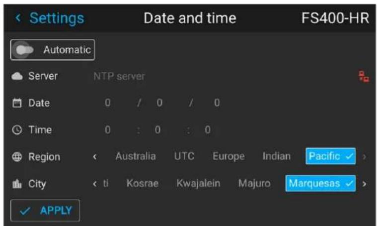
Image 10-42 Example of the Date and time menu
- Disable the Automatic slider.
Gray slider: automatic is off
Blue slider: automatic is on
- Select Date
The Date dialog is prompted. The active day is selected by default.
- Slide the Day, Month and Year slider up or down until the desired date is obtained.
or
Alternatively, use the up, down and OK buttons on the RCU or control panel until the desired date is obtained.
- Select Time.
The Time dialog is prompted. The active time is selected by default.
- Slide the Hour, Minute and second slider up or down until the desired time is obtained.
or
Alternatively, use the up, down and OK buttons on the RCU or control panel until the desired time is obtained.
- Select Apply to activate.
10.12 Date and time setup - automatically

Date is displayed by default as: day / month / year.
Time is displayed by default as: hour : minutes : seconds, in the 24-hour clock.
To set date and time automatically
- In the main menu, select Settings → Date and time.
Image 10-43
The Date and time menu is displayed.
- Enable the Automatic slider.
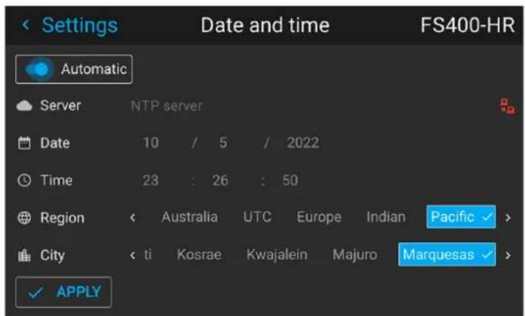
Image 10-44
Gray slider: automatic is off
Blue slider: automatic is on
- Select Server and click OK.
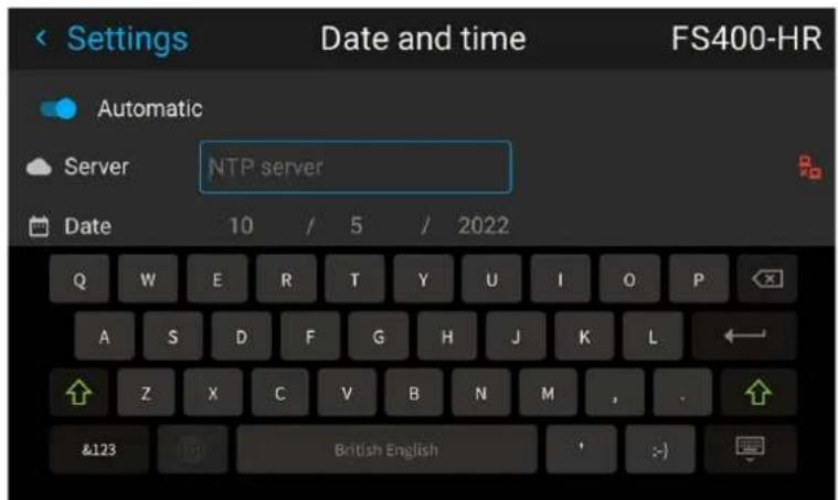
Image 10-45
- Enter the name or the IP address of the NTP server.

Tip: In case you cannot connect to an external NTP server although you can PING this server, the connection is blocked by the local firewall policy. Contact your IT system administrator.
In case the connection is successful, a green icon appears at the right side of the server line.
- Select Region and select with the arrow keys the region where the projector is installed.
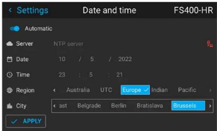
Image 10-46
The list of cities is updated according the selected region.
- Select City and select the city corresponding with your time line.
- Select Apply to activate.
10.13 Power saving settings – Standby mode
Why change the power saving features?
As a power-saving feature, if the projector is projecting no image, it will automatically go to Ready mode and later Standby mode after 15 minutes each. While in standby mode, it is no longer possible to use the OSD for anything other than the status overview of the projector. You can not access the projector menus while the projector is in Standby mode.
If you want to be able to access the projector menus for a longer period of time, or if you want to reduce the time the projector remains idle, it is best to change the power settings to your own personal preferences.
Alternatively, you can also disable this power-saving feature, ensuring that all power state transitions have to be done manually, or via remote commands (e.g. by using DMX).
How to change the power saving features?
- In the main menu, select Settings → Standby mode.
Image 10-47 Settings menu, Standby mode
The Standby mode menu is displayed.
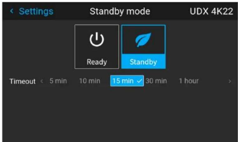
Image 10-48 Example of the Standby mode menu
- Select the desired standby time-out timeframe, or disable standby mode all together by selecting Ready.
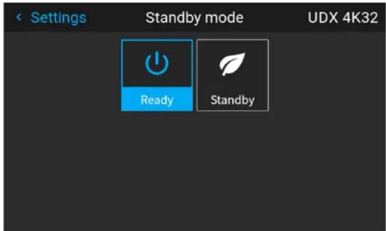
Image 10-49 Example of the Standby mode menu with Standby mode disabled

Tip: When Ready is chosen, the projector will remain in Ready mode regardless of the timeframe, unless the main power is cut or the projector is turned OFF.
10.14 Lens features
What can be done?
Some lens features can be disabled once they are correctly aligned so that a misalignment during a show is not possible.
How to enable/disable
- In the main menu, select System Settings → Lens Features.
Image 10-50 Settings menu, Lens features
The Lens features menu is displayed.
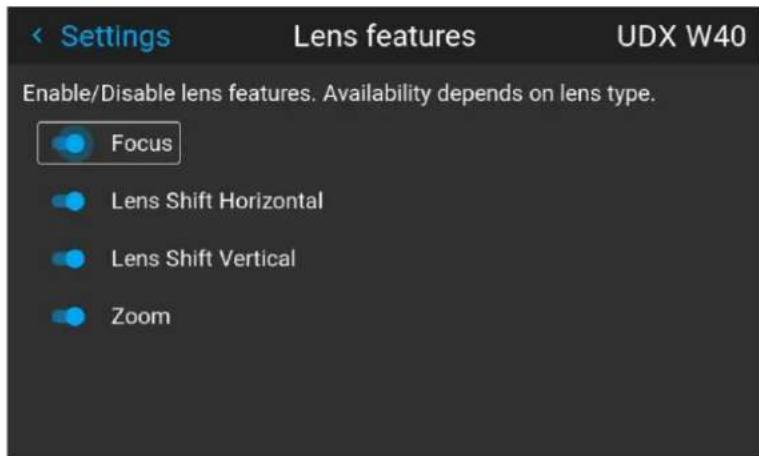
Image 10-51 Example of the lens features menu
Depending on the mounted lens type, different functions may or may not be available such as:
- Focus
• Horizontal lens shift
• Vertical lens shift -
Zoom
-
To enable/disable a feature, click on the slider and drag it to the left to disable the feature or the right to enable the feature.
When enabled, the slider becomes blue; when disabled, the slider is gray.
10.15 Factory reset
What can be done?
All settings and values on the projector can be reset to its default values. This can be done for one or more settings separately, or all settings together (factory reset).
Factory settings
The following settings are the default factory settings:

All Factory settings are listed, regardless of the projector type or chosen projector options. If an option in this list is not present in your menu, the feature is not available or enabled on your projector.
| Option / Domain | Setting Factory setting | |
| DMX DMX Mode | Basic | |
| Start Channel | 1 | |
| Auto power downArt-netXLR Connector | Disabled | |
| GSM | PIN State | Unconfirmed |
| Illumination | Power | 100% |
| Constant light output (CLO) | Disabled | |
| ImageActuator | 4K Actuator enabled / disabled | Enabled |
| Blend | Blend / Mask sizeBlack Level | Disabled, all value to zero |
| Black Level Files | Disabled. | |
| Blend Files Note: All uploaded blend and black level files will be deleted | ||
| ImageCapture Camera | Camera disabled, all measurements reset to 0 | |
| Connectors Signal range | Auto | |
| Color space Auto | ||
| EDID Default EDID for projector type | Note: All uploaded custom EDID files w be deleted. | |
| Convergence Electronic Convergence All values to zero | ||
| Display Display mode | AutoStereo | |
| Image features | Contrast | mid value |
| Brightness | mid value | |
| Saturation | mid value | |
| Sharpness | mid value | |
| Gamma mid value, auto | ||
| Digital Shift and Zoom | Disabled, set to mid values | |
| Cropping | Off | |
| Aspect Ratio | 16:9 | |
| Scaling | Fill Aspect ratio | |
| Orientation | Orientation | Table, Front |
| RealColorTM P7 | P7 RealcolorTM | all set to native |
| Resolution | Output Resolution | 4K UHD (4K devices)WQXGA (W devices)WUXGA (U devices) |
| Source | Source files | Standard |
| 3D | Sync delay | 0 μs |
| Swap eye | Off | |
| Dark time | lowest value available | |
| Test patterns | Test Pattern | Off, none selected,Note: All uploaded custom test patterns will be deleted |
| Uniformity | DynaBlack | Off |
| Warp | Screen size | 5120x3200 / 2560x1600 |
| 4 cornerBow | Warp disabled, no warp | |
| Warp files | DisabledNote: all uploaded warp files will be deleted | |
| Network | Communication | LAN, Automatic settings |
| Optics | High Contrast | Off |
| Peripheral Settings | for External Cooler Cooling mode set to | internal. |
| Settings for Motorized Frame All values | to mid value | |
| Profiles Settings for | projector profiles All profiles will be deleted | |
| Screen Screen luminance unit nits | ||
| System Auto off / Eco Mode / Standby Mode (depending on availability) | Enabled | |
| Time | Time server | Automatic disabled, NTP server removed |
| Date | 0 / 0 / 0 | |
| Time | 0 : 0 : 0 | |
| Region / City | UTC | |
| User | User profiles | Only default users remain |
| Capture mode | Disabled | |
| User interface | Theme | Dark |
| Units - Temperature | °C | |
| Units - Length | Meters (m) | |
| Language | English | |
| Backlight - Stealth Mode Backlight - Timeout | Off5 minutes | |
How to reset all projector settings
- In the main menu, select Settings → Maintenance → Reset.
Image 10–52 Settings menu, factory reset
The Reset menu is displayed.
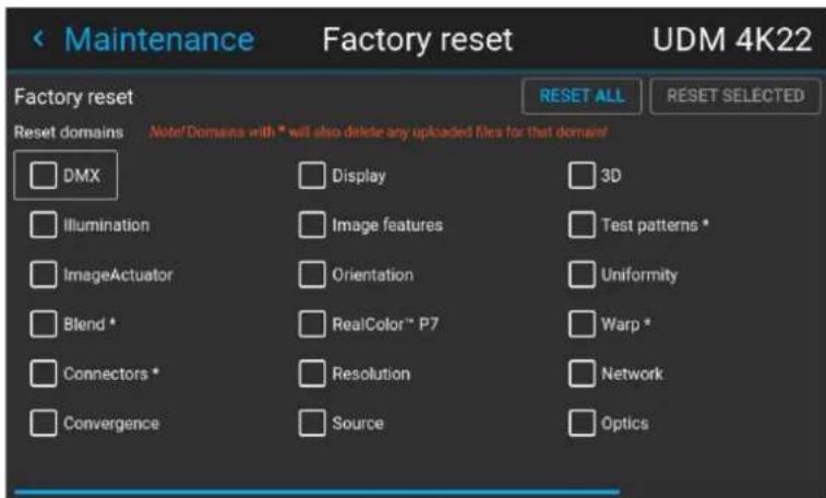
Image 10-53 Example of the reset menu
- In the Reset menu, select RESETALL and confirm with OK.
How to reset one or more projector settings
- In the main menu, select Settings → Maintenance → Reset.
Image 10-54 Settings menu, factory reset
The Reset menu is displayed.
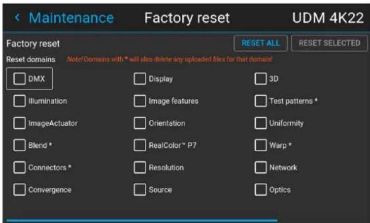
Image 10-55 Example of the reset menu
- Navigate to the checkbox next to the settings that need to be reset and press OK. Multiple selections are possible.
- Select RESET SELECTED and confirm with OK to reset all selected settings.
10.16 Lens Calibration
How to calibrate
- In the main menu, Settings → Maintenance → Lens Calibration.
Image 10-56 Maintenance menu, lens calibration
The Lens Calibration menu is displayed, alongside the status of each
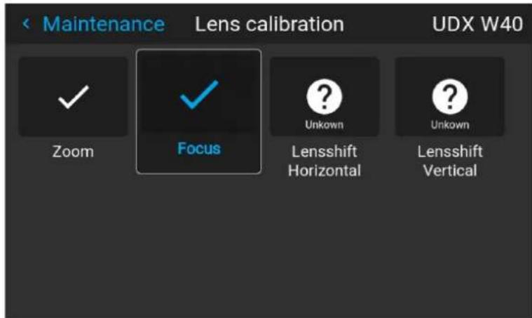
Image 10-57 Example of the lens calibration menu
- In the Lens Calibration menu, select the desired calibration action and click OK.
You can select one of the following functions, depending on the type of mounted lens:
• Horizontal lens shift
- Vertical lens shift
- Focus
- Zoom
The text Calibrating will be displayed in the icon of the selected function until the calibration is completed.
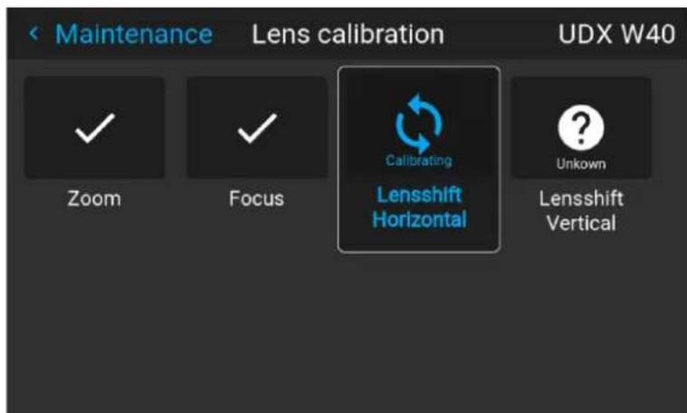
Image 10–58 example of calibration in progress
When an error is detected, the message Calibration Error is displayed next to function.
10.17 Flex brightness

This feature is available by default on the following devices: UDX 4k40, UDX W40.
This feature is also available as an option on the following devices: UDX 4K32, UDX 4K26, UDX W32, UDX W26.
Overview
With the FLEX technology the projector owners can lock the light output to different levels. The locking can be done via 3 different ways:
- Via Projector Toolset when connected via an ethernet connection with the projector. For more information on how to set up and use the Flex license, see the Projector Toolset's user guide, chapter “Configuration, License / registration”.
- Via Barco Insights Management Suite when the GSM module is installed. For more information on how to set up and use the Flex license, see Projector Management Suite user guide, chapter "Projector Configuration tab" – "Flex brightness"
• Via the OSD menu of the projector itself
To lock to a specific value a 4 digit code is necessary. These codes can be created by the projector owner using Projector Toolset or the Projector Management Suite.
Availability
The flex brightness function is license protected. This license is already available in the projector. To activate the flex brightness a flex code is necessary. This flex code can be requested for free and uploaded via Projector Toolset or the Projector Management Suite. For more information about uploading this flex code, see Projector Toolset's user guide, chapter “FLEX, light output control”.
For other models, Flex brightness is an option. You can order and buy a license file. This license file is linked with the projector type and projector serial number. Once you received you license file, upload this file via Projector Toolset to your projector. Once the file is uploaded, the same file has to be used to upload the Flex code.
Flex codes
Once your flex code is correctly uploaded, the projector creates a number of flex codes, one for each possible maximum light output. These codes are used for rental activities when adapting the light output of the projector.
The created flex codes are only visible in Projector Toolset and the Projector Management Suite by the projector owner. To make these visible he will need his license for this typical projector.
Maximum Light output setup via OSD menu
- In the main menu, select Settings → Maintenance → Flex.
Image 10-59 Maintenance menu, Flex
The Flex license menu is displayed.
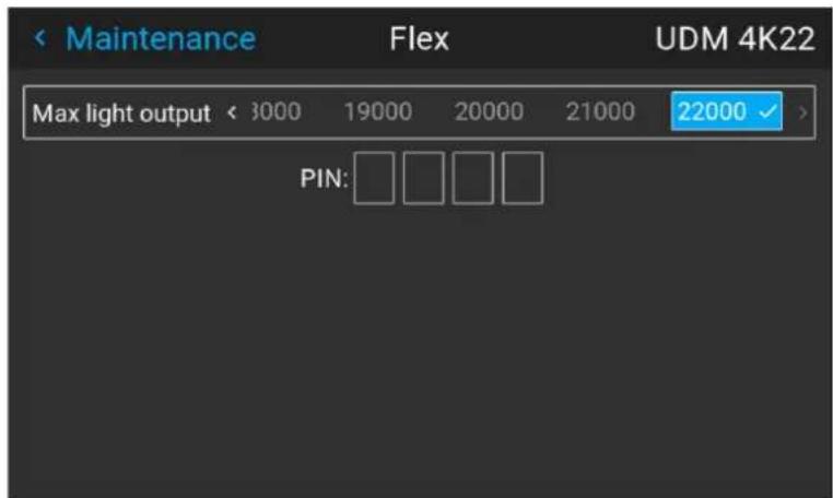
Image 10-60 Example of the Flex license menu
- Choose the desired Light output (in lumens) for which you have a code available.
- Enter the code via the OSD menu and confirm.
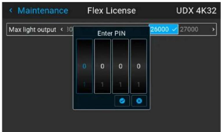
Image 10-61 Example of entering the code in the Flex license menu
10.18 Rigging frame Calibration
How to calibrate the motorized rigging frame
- In the main menu, select Settings → Maintenance → Frame Calibration.
Image 10-62 Maintenance menu, Frame calibration
The Frame calibration menu is displayed.
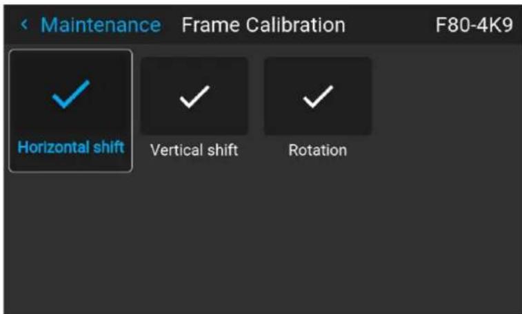
Image 10-63 Example of the Frame calibration menu
- In the Frame Calibration menu, select the desired calibration action and click OK.
You can select one of the following functions:
• Horizontal shift
- Vertical shift
- Rotation
The text Calibrating will be displayed until the calibration is completed.
Image 10–64 Example of a calibration in progress
When an error is detected, the message Calibration Error is displayed next to function.
10.19 Electronic Convergence
What can be done?
The convergence patterns can be used to check the convergence alignment of red, green and blue. If there is a misalignment of at least one 1 pixel, an electronic realignment is possible.
Mechanical realignment of the convergence can only be done by a qualified service technician.
How to display the convergence settings
- In the main menu, navigate to Settings → Maintenance → Electronic Convergence.
Image 10-65 Maintenance menu, electronic convergence
The Electronic Convergence menu is displayed.
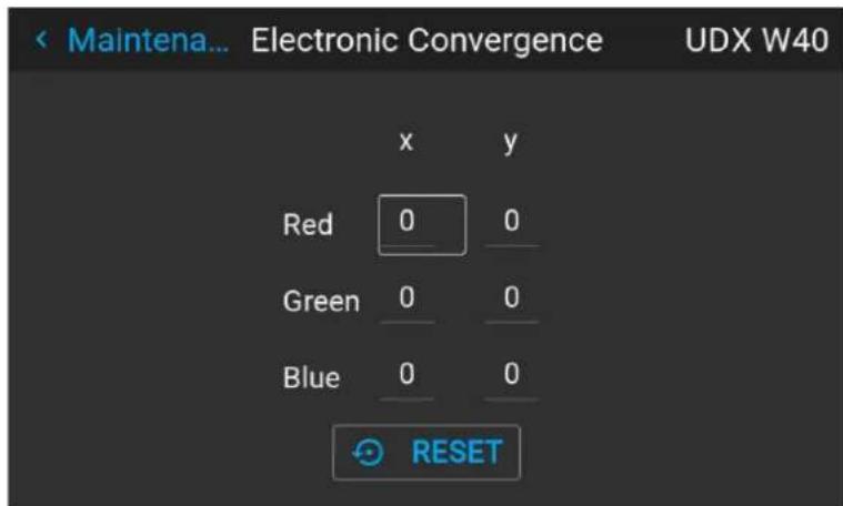
Image 10-66 Example of the electronic convergence menu
- Select the desired X or Y value for one of the three colors and confirm.
- Use the arrow keys to raise or lower the value and confirm.
- Confirm all changes by pressing Enter.
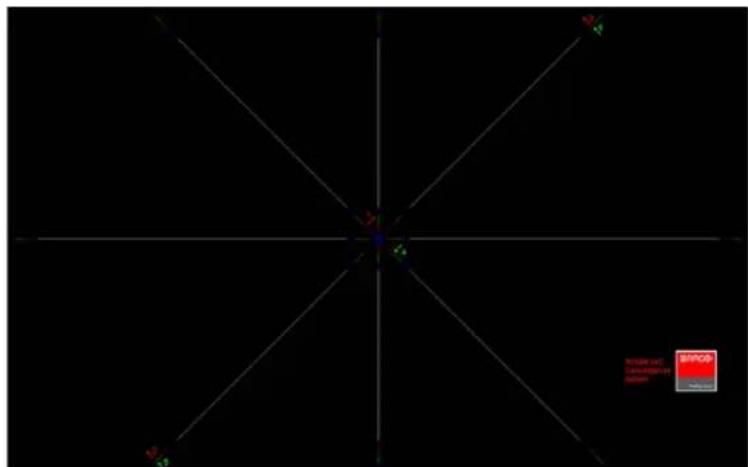
Image 10-67

Tip: Press Reset to return all values to the factory settings.
- Repeat all steps until the desired alignment is achieved.
10.20 Setting up the external cooler on a UDX
Using the external cooler
When the external cooler for the projector is correctly installed, the Cooling menu will be enabled and visible in the menu.
Using the Cooling menu, you can choose between the following cooling methods:
- Internal: Use only the internal cooling system of the projector (default).
- External: Use only the external cooling system of the projector. This method is preferred when the cooler is in a different location than the projector and you want the projector to operate in "silent mode".
- Mixed: Use both the external and internal cooling. Can be used to extend the lifetime of the internal cooler of the projector.
How to set up the external cooler
- In the main menu, select Installation → Cooling.
Image 10-68 Installation menu, Cooling
The Cooling menu is displayed.
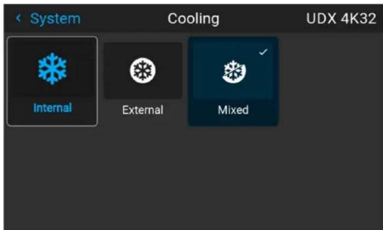
Image 10-69 Example of the cooling menu
- In the Cooling menu, select the desired cooling option.

Note: After changing the settings, it can take up to 1 minute for the changed settings to take effect.
10.21 Capture mode
Why use capture mode?
Various technical features are used inside the projector to display the best possible image on the projected surface. However, in expositions and setups where visitors are expected to film or take pictures of the projected surface, some of these technical features may have side-effects on the captured footage, such as solarization.
Enabling the Capture mode feature disables some of the technical features of the projector that are known to cause solarization and gives the visiting audience an experience they can “capture” and post on social media without worries.
How to enable Capture mode
-
In the main menu, navigate to Settings → System.
-
In the Lens menu, click Capture mode to toggle between On and Off.
Image 10-70 System menu, Capture mode disabled Image 10-71 System menu, Capture mode enabled
10.22 Login to advanced settings
How to login
- In the main menu, Settings → Maintenance → Login.
Image 10-72
The Login menu is displayed.
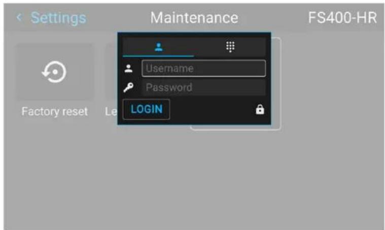
Image 10-73
There are 2 ways to login:
• Via user & password, go to step 2
• Via a digit code, go to step 5
- To login via user & password, select User and click OK.
- Navigate to user name and click OK.
A keyboard is displayed. Enter the user name
Navigate to Password and enter the password.
- Select LOGIN and click OK to login.
- To login via digit code, select digit keyboard and click OK.
- Navigate to Pin code and click OK.
A keyboard is displayed. Enter the pin code.
10.23 List of open source licenses
About open source licenses
Open source licenses are licenses that comply with the Open Source Definition. In brief, they allow software to be freely used, modified, and shared.
To be open and transparent about the open source software used on the projector, there is a list of all open source licenses available in the software.
How to find the open source licenses
For the complete and most up-to-date list of the used open source software and the version used, go to the main menu and select Settings → General → Open source licenses.

Image 10-74 General menu - Open source licenses
Advanced Settings
11
11.1 Remote access – Enable source preview 160
11.2 Remote access – Enable camera preview 161
11.3 Advanced Settings – Color 162
11.4 Advanced Settings – Statistics.... 163
11.5 Checking the status of the Laser Banks 164
11.6 Advanced settings – Tilt sensor calibration 165
About the Advanced Settings menu
The Advanced Settings and Remote access menus are hidden by default for the regular user. you can only make these menus visible after entering a User name and Password or a Service code with the remote control. See "Login to advanced settings", page 156 for more info.
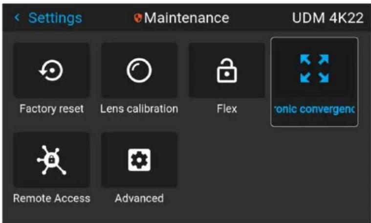
Image 11-1 Example of the Maintenance menu, with the Advanced menu and Remote access menu unlocked

The Advanced Settings and Remote access menu items will remain visible until you leave the Maintenance menu.
11.1 Remote access – Enable source preview
Source preview
Up until Pulse software 2.0. x, you were able to see a preview of the connected source when you remotely accessed the projector. This was a feature you could disable using Projector Toolset.
However, from Pulse 2.1. x onward, this feature is disabled by default and can now be enabled in both Projector Toolset and the Pulse GUI.

Upgrading your projector from a software version 2.0.x or older to 2.1.x or newer will disable Source preview by default. Once the software has been successfully upgraded, you can always opt to enable this feature again.
How to enable source preview
- In the main menu, select Settings → Maintenance and login to visualize the hidden Remote access menu.
- Select Remote access.
Image 11-2 Maintenance menu, Remote access
The Remote access menu is displayed.
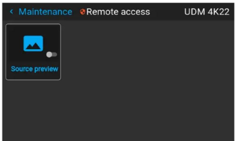
Image 11-3 Example of the Remote access menu
- Enable the slider to enable the source preview feature.
Image 11-4 Remote access menu, Source preview is enabled
11.2 Remote access – Enable camera preview
Camera preview
Up until Pulse software 2.0.x, you were able to see the footage of the camera when you remotely accessed the projector. This was a feature you could disable using Projector Toolset.
However, from Pulse 2.1. x onward, this feature is disabled by default and can now be enabled in both Projector Toolset and the Pulse GUI.

Upgrading your projector from a software version 2.0.x or older to 2.1.x or newer will disable Camera preview by default. Once the software has been successfully upgraded, you can always opt to enable this feature again.
How to enable Camera preview
- In the main menu, select Settings → Maintenance and login to visualize the hidden Remote access menu.
- Select Remote access.
Image 11-5 Maintenance menu, Remote access
The Remote access menu is displayed.
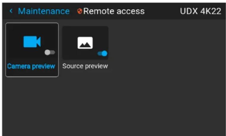
Image 11–6 Example of the Remote access menu
- Enable the slider to enable the Camera preview feature.
Image 11-7 Remote access menu, Camera preview is enabled
11.3 Advanced Settings - Color

CAUTION: The native colors have been measured and set during factory production. Do not change them, unless parts of the optical path have been replaced due to servicing. If you need to change the native colors on the device, make sure to also perform a P7 calibration, using the Projector Toolset and a chroma meter. For more info on P7 calibration, refer to the Projector Toolset Reference guide.
How to adjust the P7 native settings
- In the main menu, navigate to Settings → Maintenance → Advanced, while you are logged in.
Image 11-8 Maintenance menu, Advanced
- In the Advanced Settings menu, select Native RealColor.
Image 11-9 Advanced Settings, Native Realcolor
The RealColor calibration menu will be displayed.
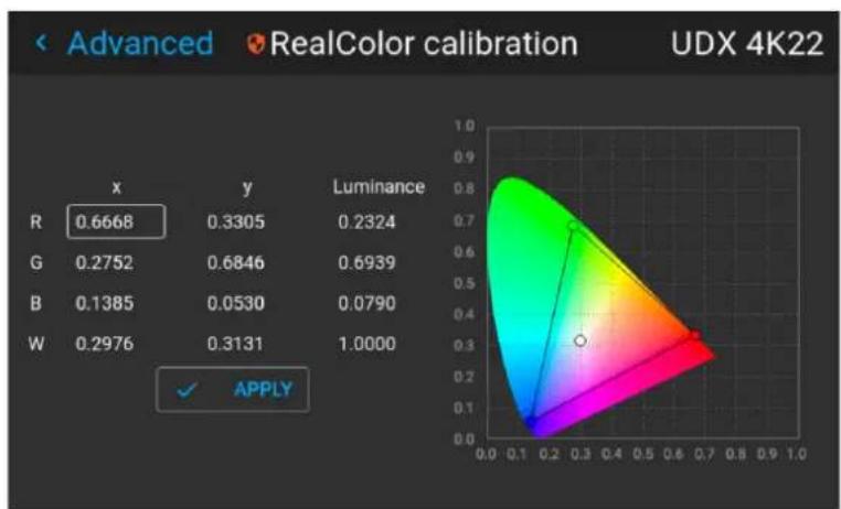
radar
| | x | y | Luminance | | ------ | ----- | ------ | --------- | | R | 0.6668| 0.3305 | 0.2324 | | G | 0.2752| 0.6846 | 0.6939 | | B | 0.1385| 0.0530 | 0.0790 | | W | 0.2976| 0.3131 | 1.0000 |Image 11-10 Example of the RealColor calibration menu
- Select the desired value to change and confirm.
- Change the values to the desired position, taking into account the color gamut values.
- Select APPLY and confirm.
11.4 Advanced Settings – Statistics
What can be seen?
The statistics screen shows the general information about the projector, spread over two tab pages. The following items will be displayed:
- Laser runtime
- Laser Strikes
- Laser bank x runtime
- Projector runtime
- System runtime
- System uptime
How to display the statistics
- In the main menu, navigate to System Settings → Maintenance → Advanced Settings, while you are logged in.
Image 11-11 Maintenance menu, Advanced
- In the Advanced Settings menu, select Statistics.
Image 11–12 Advanced settings, Statistics
The Statistics will be displayed.
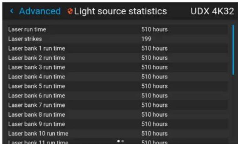
Image 11–13 Example of the Statistics menu
11.5 Checking the status of the Laser Banks
About failing laser banks
The projector is powered by a laser light source, which has multiple laser banks. The light output and color performance is dependant on the number of active laser banks.
If one or more laser banks have failed of a certain type, you will notice a decreased light input and decrease i color performance. But the projector will keep on playing, unless too many banks of a certain color will have failed.

In order to disable a certain laser bank, or calibrate the projector after disabling one or more laser banks, please refer to the Projector Toolset User Manual.
How to check the status of the Laser Banks
- In the main menu, navigate to Settings → Maintenance → Advanced, while you are logged in.
Image 11–14 Maintenance menu, Advanced
- Enter the service code.
- In the Service menu, select Laser Banks.
Image 11–15 Advanced menu, Laser banks
The Laser group statistics menu is displayed.
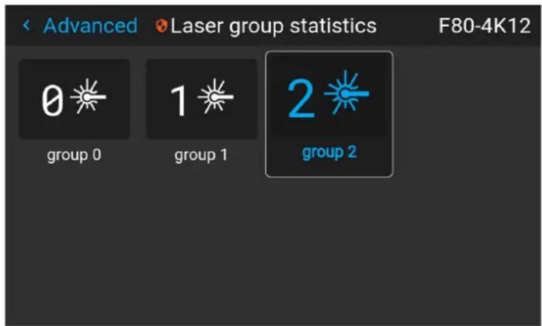
Image 11–16 Example of the Laser group statistics menu
- Select the desired laser group.
- In the laser banks group page, you can see which laser banks are part of this specific group. You can also see which laser banks are operational and which have failed.
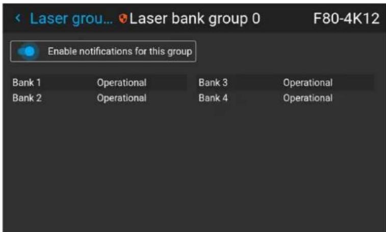
Image 11–17 Example of the laser bank group menu
- If you want notifications to be disabled for a specific group of laser banks, disable the Enable notifications for this group slider.
11.6 Advanced settings - Tilt sensor calibration

CAUTION: The calibration procedure resets the values of the tilt sensor to 0 in the current position of the projector. For the optimal working of the tilt sensor it is important to make sure the projector is perfectly level when performing this procedure. If not, the tilt sensor will not function as desired once the calibration has been completed.
Required tools
Level
How to calibrate the tilt sensor?
- Place the projector on a flat surface and make sure it is positioned level in all directions. Use a level tool to help ensure this.
- In the main menu, navigate to Settings → Maintenance → Advanced, while you are logged in.
Image 11–18 Maintenance menu, Advanced
- Enter the service code.
- In the Service menu, select Tilt sensor calibration.
Image 11–19 Advanced menu, Tilt sensor calibration
- Confirm your action.
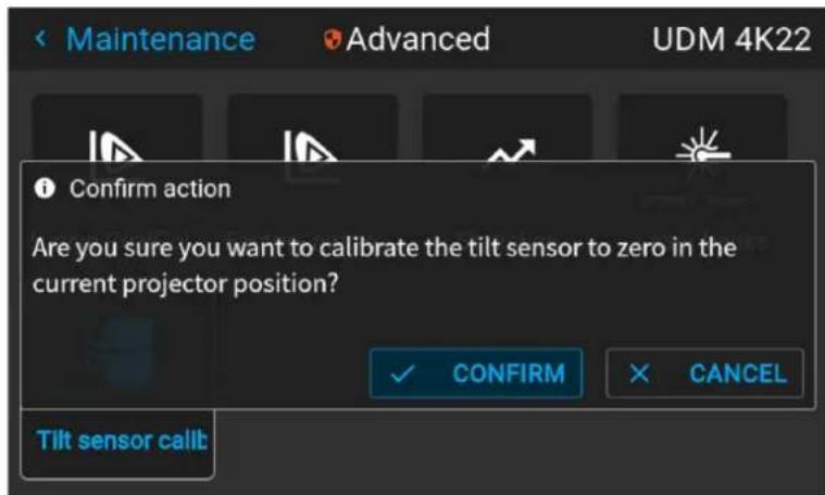
Image 11–20 Example of the Advanced menu with the Tilt sensor menu
The tilt sensor will be set to zero in the current position of the projector.
GUI - Status menu
12
12.1 Status menu overview.... 168

No settings can be modified in the status menu. Its only for consulting.
12.1 Status menu overview
How to access the status menu
While in the main menu, press Status.
Image 12-1 Main menu, status
The status menu is displayed.
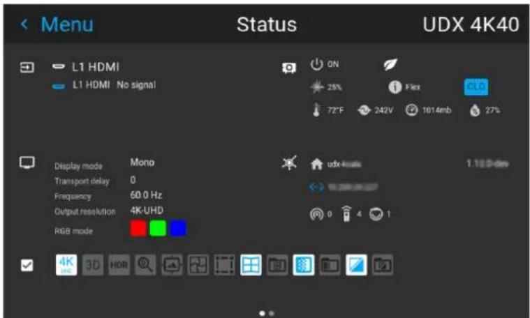
Image 12-2 Example of the first page of the status menu
Swipe the screen left of right to swap between the Status pages.
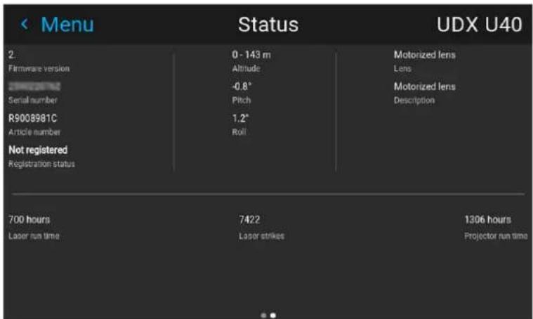
Image 12-3 Example of the second page of the Status menu
What can be seen on the Status page?
- Connected source and signal details
- Display settings (e.g. display mode, transport delay, output resolution, etc)
- Projector power and environmental details (e.g. power, temperature, pressure, etc)
• Network status (e.g. host name, IP address, software version)
• Active function icons (e.g. warp, blend, files, etc). Active functions are highlighted, while inactive functions are muted.
What can be seen on the About page?
- Projector information, e.g. firmware version, serial number, projector article number and registration status (only if applicable for your device)
- Mounted lens: Lens type and Lens description (if available).
• Installation information: Altitude, pitch angle, roll angle, distance (only if applicable for your device) - Basic statistics, Light source run time, light source strikes, projector runtime.
Projector maintenance
13
13.1 Software update 172
13.2 Cleaning the lens.... 173
13.3 Cleaning the exterior of the projector.... 174
About this chapter
This chapter contains general maintenance procedures.
13.1 Software update

CAUTION: Do not power off or unplug the projector while the software update is ongoing.
How to update the software
- Power on the projector. Wait until the Power on/off button is lit white or blue.
- Download and install the latest version of Projector Toolset for Pulse. The program can be downloaded for free from Barco's website, (URL: http://www.barco.com). Click on myBarco and log in to get access to secured information. Registration is necessary.
If you are not yet registered, click on New to myBarco and follow the instructions. With the created login and password, it is possible to log in where you can download the software. - Download the latest firmware (format .fw) from Barco's website in the same way as for Projector Toolset.
- Start Projector Toolset and make a connection with the projector. For more information, see the "Projector Toolset" user guide.
- Select tab Update settings.
- Fill out the path to the update file (1)

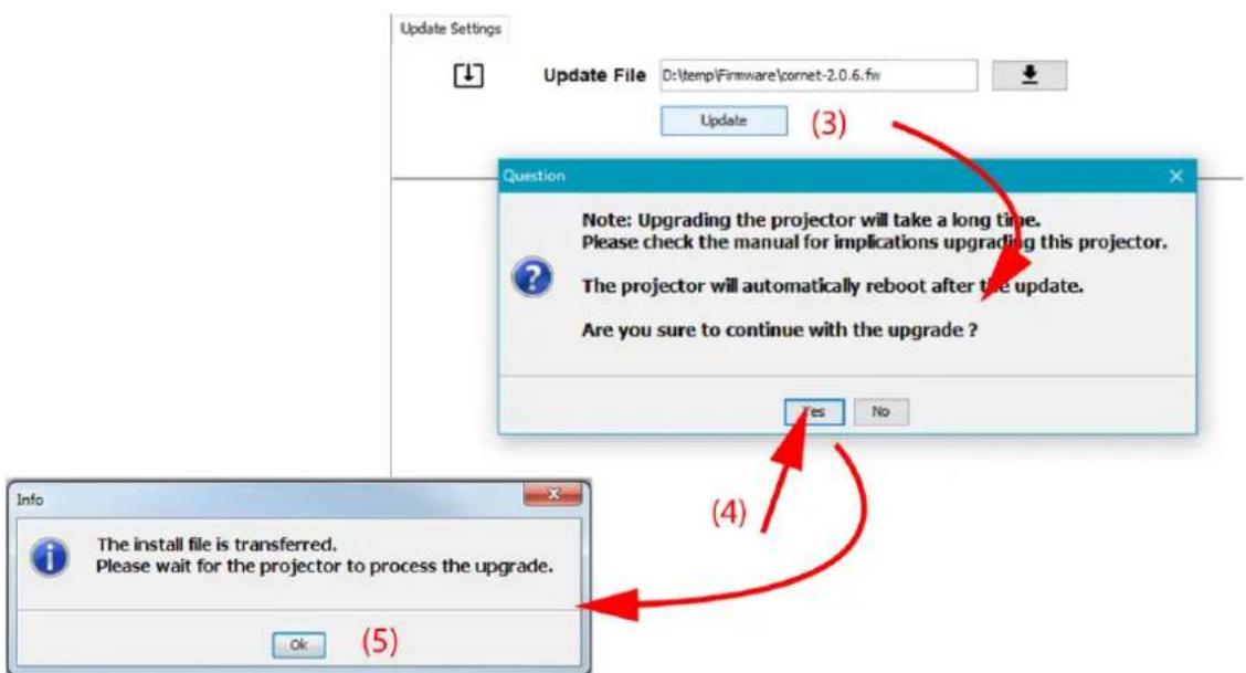
Image 13-1 Update Pulse projector
or
click on the path selection icon (2) to open a browser window.
- Browse to the desired update package (format .fw) and click Select Update Package.
The path will be filled out in the input field next to Update File.
- Click Update (3).
The update starts. This action can take a long time. A message is displayed.
- Click Yes to continue (4).
The update file will be transferred to the projector and installed. The projector will reboot.
A message is displayed. Click Ok to clear the message.
How to update the software if the projector isn't connected to the network
-
Power on the projector. Wait until the Power on/off button is either lit white or blue.
-
Download the latest firmware file ( format .fw) from Barco's website. The firmware can be downloaded for free from Barco's website, (URL: http://www.barco.com). Click on myBarco and log in to get access to secured information. Registration is necessary.
If you are not yet registered, click on New to myBarco and follow the instructions. With the created login and password, it is possible to log in where you can download the software.
- Place the firmware file on a clean USB flash drive.

Note: Make sure the flash drive is FAT32 compatible & no other files are on the flash drive.
- Plug the flash drive in the USB port on the Communication Panel.
The update file will be transferred to the projector and installed. The projector will reboot when completed.

CAUTION: While it is technically possible to "downgrade" the software to an older version using this method, it is NOT recommended and should be avoided as much as possible. Certain features will no longer be supported, projectors can display unwanted behavior during the downgrade and in some rare cases, this may even bring damage to the device. Always contact Barco if you want to make sure a downgrade will not hurt your device.

Take note that the update process can take a long time to complete.

For more info about the Projector Toolset see user guide of the Projector Toolset.
13.2 Cleaning the lens

To minimize the possibility of damage to optical coatings, or scratches to lens surfaces follow the cleaning procedure as described here precisely.
Required tools
- Compressed air
- Clean micro fiber lens cleaning cloth (e.g. Toraysee® cloth(s))
- Clean cotton cloth
- Lens cleaner (e.g. ZEISS lens cleaner, Purosol™ or other water based lens cleaner products)
How to clean the lens?
- Blow off dust with clean compressed air (or pressurized air) cans
- Clean with lens cleaner together with a clean lens cleaning cloth to remove the dust and contamination. Use big wipes in one single direction.

Warning: Do not wipe back and forwards across the lens surface as this tends to grind dirt into the coating.
-
Use a dry lens cleaning cloth to remove left liquid or stripes. Polish with small circles.
-
If there are still fingerprints on the surface, wipe them off with lens cleaner together with a clean lens cleaning cloth. Polish again with a dry one.

If smears occur when cleaning lenses, replace the cloth. Smears are the first indication of a dirty cloth.
13.3 Cleaning the exterior of the projector
How to clean the exterior of the projector?
- Switch off the projector and unplug the projector from the mains power net.
- Clean the housing of the projector with a damp cloth. Stubborn stains may be removed with a cloth lightly dampened with a mild detergent solution.
Specifications
A
A.1 Specifications of the UDX-4K40....176
A.2 Specifications of the UDX-4K32 177
A.3 Specifications of the UDX-4K26 179
A.4 Specifications of the UDX-4K22 180
A.5 Specifications of the UDX-W40 182
A.6 Specifications of the UDX-W32 184
A.7 Specifications of the UDX-W26 185
A.8 Specifications of the UDX-W22 187
A.9 Specifications of the UDX-U45LC 188
A.10 Specifications of the UDX-U40....190
A.11 Specifications of the UDX-U32....191
A.12 Specifications SDI inputs.... 193
A.13 Specifications HDMI inputs.... 194
A.14 Specifications HDBaseT inputs.... 194
A.15 Specifications DisplayPort 1.2 inputs....195
A.16 Specifications SFP inputs.... 197
About this chapter
This chapter gives an overview of the projector specifications.
A.1 Specifications of the UDX-4K40
Specifications
| Projector type 4K UHD 3-chip DLP digital projector | |
| Technology 0.9" DMDTM x3 | |
| Resolution 3,840 x 2,400 (4K UHD) / 2,560 x 1,600 (native) / 5,120 x 3,200 (processing) | |
| Brightness 37,500 (WQ)/36,500 (4K UHD) center lumens // 36,500 (WQ)/35,500 (4K UHD) ansi lumen // 40,000 ISO | |
| Contrast ratio Full field 2200:1 / Barco Dyna Black 20000:1 | |
| Brightness uniformity 95% | |
| Aspect ratio 16:10 | |
| ScenergiX Horizontal and vertical edge blending | |
| Lenses TLD+ 0.37, 0.65-0.85, 0.8-1.16:1; 1.25-1.6:1; 1.5-2.0:1; 2.0-2.8:1; 2.8-4.5:1; 4.5-7.5:1; 7.5-11.5:1 | |
| Optical lens shift Vertical between -100% to +130%, depending on lensHorizontal up to +/- 40%, depending on lensMotorized zoom and focus (with lens memory on TLD lenses)Motorized lens shift (with position memory on all lenses) | |
| Color correction P7 | |
| Light source | laser phosphor with inorganic phosphor wheel |
| Light source lifetime | 20,000 hrs |
| Optical dowser | Digital |
| Picture-by-picture | Two sources simultaneously |
| Orientation | 360° |
| Sealed DLPTM core | standard |
| DMX 512 | standard |
| WARP | Direct adjust OSD + toolset |
| Image processing | Embedded warp & blend |
| Keystone correction | Yes |
| Integrated web server | Yes |
| CLO (constant light output) | Standard |
| 3D | Active eye wear (optional), passive circular (optional); 2 flash up to 200Hz*; optional Dual Eye Point 240Hz |
| Inputs | Single HDBaseT; HDMI2.0 (HDCP2.2, HDR10); DP 1.2 (HDCP 1.3); Quad 3G/12G SDI / BarcoLink ULTRA |
| Optional Inputs | Quad DP1.2 / Fiber SFP |
| Input resolutions | From NTSC up to 4K (4,096 x 2,160) refresh rates:24hz to 120hz 4K/4KUHD (4096 x 2160/ 3860 x 2400) to 240hz WQXGA (2560 x 1600) |
| Max. pixel clock 600 MHz | |
| Software tools Projector Toolset + Android app + iOS app | |
| Control XLR wired + IR, RS232, Wifi (opt), GSM (opt) | |
| Network connection 10/100 base-T, RJ-45 connection, Wifi (optional) | |
| Power requirements 120-160 V (reduced power) / 200-240V (+/- 10%), 20A, 50-60Hz | |
| Max. power consumption 3750W | |
| Noise level (typical at 25°C58dB(A)77°F) | |
| Operational ambient temperature | 0-40°C / 32°-104°F (reduce power >40°C) |
| Operational humidity 0-80% (non condens) | |
| Dissipation BTU Max. 12,795 BTU/h | |
| Dimensions (WxLxH) 660 x | 830 x 350 mm / 25.98 x 32.67 x 13.77 inches |
| Shipping Dimensions (WxLxH) | 800 x 1,200 x 685 mm / 31.49 x 47.24 x 26.96 inches |
| Weight 92kg (202 lbs)/shipping weight from factory: 110kg (242 lbs) | |
| Standard accessories Power cord, wireless/XLR wired rugged remote control | |
| Certifications | Compliant with UL60950-1 and EN60950-1 complies with FCC rules & regulations, part 15 Class A and CE EN55032 Class A, Rohs |
| Warranty | 3 years |
A.2 Specifications of the UDX-4K32
Specifications
| Projector type | 4K UHD 3-chip DLP digital projector |
| Technology | 0.9" DMDTM x3 |
| Resolution | 3,840 x 2,400 (4K UHD) / 2,560 x 1,600 (native) / 5,120 x 3,200 (processing) |
| Brightness | 31,000 (WQ)/30,000 (4K UHD) center lumens* // 30,000 (WQ)/29,000 (4K UHD) ansi lumens // 33,000 ISO |
| Contrast ratio | Full field 2200:1 / Barco Dyna Black 20000:1 |
| Brightness uniformity | 95% |
| Aspect ratio | 16:10 |
| ScenergiX | Horizontal and vertical edge blending |
| Lenses | TLD+ 0.37, 0.65-0.85, 0.8-1.16:1 ; 1.25-1.6:1 ; 1.5-2.0:1 ; 2.0-2.8:1 ; 2.8-4.5:1 ; 4.5-7.5:1 ; 7.5-11.5:1 |
| Optical lens shift | Vertical between -100% to +130%, depending on lensHorizontal up to +/- 40%, depending on lensMotorized zoom and focus (with lens memory on TLD lenses) Motorized lens shift (with position memory on all lenses) |
| Color correction P7 | |
| Light source laser phosphor | with inorganic phosphor wheel |
| Light source lifetime 25,000 hrs | |
| Optical dowser Digital | |
| Picture-by-picture Two sources simultaneously | |
| Orientation 360° | |
| Sealed DLPTM core standard | |
| DMX 512 standard | |
| WARP Direct adjust OSD + toolset | |
| Image processing Embedded warp & blend | |
| Keystone correction Yes | |
| Integrated web server Yes | |
| CLO (constant light output) Standard | |
| 3D | Active eye wear (optional), passive circular (optional); 2 flash up to 200Hz*; optional Dual Eye Point 240Hz |
| Inputs | Single HDBaseT; HDMI2.0 (HDCP2.2, HDR10); DP 1.2 (HDCP 1.3); Quad 3G/12G SDI / BarcoLink ULTRA |
| Optional Inputs | Quad DP1.2 / Fiber SFP |
| Input resolutions | From NTSC up to 4K (4,096 x 2,160) refresh rates: 24hz to 120hz 4K/4KUHD (4096 x 2160/ 3860 x 2400) to 240hz WQX (2560 x 1600) |
| Max. pixel clock | 600 MHz |
| Software tools | Projector Toolset + Android app + iOS app |
| Control | XLR wired + IR, RS232, Wifi (opt), GSM (opt) |
| Network connection | 10/100 base-T, RJ-45 connection, Wifi (optional) |
| Power requirements | 120-160 V (reduced power) / 200-240V (+/- 10%), 20A, 50-60Hz |
| Max. power consumption | 2,900W nom/3,100W max / STBY less than 10W |
| Noise level (typical at 25°C) 52dB(A) | |
| Operational ambient temperature | 0-40°C / 32°-104°F |
| Operational humidity | 0-80% (non condens) |
| Dissipation BTU | Max. 9,895 BTU/h |
| Dimensions (WxLxH) | 660 x 830 x 350 mm / 25.98 x 32.67 x 13.77 inches |
| Shipping Dimensions | (WxLxH) 800 x 1,200 x 685 mm / 31.49 x 47.24 x 26.96 inches |
| Weight | 92kg (202 lbs)/shipping weight from factory: 110kg (242 lbs) |
| Standard accessories Power | cord, wireless/XLR wired rugged remote control |
| Certifications Compliant with | UL60950-1 and EN60950-1 complies with FCC rules & regulations, part 15 Class A and CE EN55032 Class A, Rohs |
| Warranty 3 years | |
| * +/- 10% | |
A.3 Specifications of the UDX-4K26
Specifications
| Projector type 4K UHD 3-chip DLP digital projector | |
| Technology 0.9" DMDTM x3 | |
| Resolution 3,840 x 2,400 (4K UHD) / 2,560 x 1,600 (native) / 5,120 x 3,200 (processing) | |
| Brightness 26,000 (WQ)/25,000 (4K UHD) center lumens // 25,000 (WQ)/24,000 (4K UHD) ansi lumens // 28,000 ISO | |
| Contrast ratio Full field 2200:1 / Barco Dyna Black 20000:1 | |
| Brightness uniformity 95% | |
| Aspect ratio 16:10 | |
| ScenergiX | Horizontal and vertical edge blending |
| Lenses | TLD+ 0.37:1; 0.65:1; 0.73:1; 0.85:1; 1.2:1; 1.25 -1.6:1; 1.5-2.0:1; 2.0-2.8:1; 2.8-4.5:1; 4.5-7.5:1; 7.5-11.5:1 |
| Optical lens shift | Vertical between -100% to +130%, depending on lensHorizontal up to +/- 40%, depending on lensMotorized zoom and focus (with lens memory on TLD lenses)Motorized lens shift (with position memory on all lenses) |
| Color correction | P7 |
| Light source | Laser phosphor with inorganic phosphor wheel |
| Light source lifetime | 40,000 hrs |
| Optical dowser | standard |
| Picture-by-picture | Two sources simultaneously |
| Sealed DLPTM core | standard |
| Orientation | 360° |
| DMX 512 | standard |
| WARP | Direct adjust OSD + toolset |
| Image processing | Embedded warp & blend |
| Keystone correction | Yes |
| Integrated web server | Yes |
| CLO (constant light output) | Standard |
| 3D Active eye wear (optional), passive circular (optional); 2 flash up to 200Hz*; optional Dual Eye Point 240Hz | |
| Inputs Single HDBaseT; HDMI2.0 (HDCP2.2, HDR10); DP 1.2 (HDCP 1.3); Quad 3G/12G SDI / BarcoLink ULTRA | |
| Optional Inputs Quad DP1.2 / Fiber SFP | |
| Input resolutions From NTSC up to 4K (4,096 x 2,560) refresh rates: 24hz to 120hz 4K/4KUHD (4096 x 2160/ 3860 x 2400) to 240hz WQXGA (2560 x 1600) | |
| Max. pixel clock 600 Mhz | |
| Software tools Projector Toolset + Android app + iOS app | |
| Control XLR wired + IR, RS232, Wifi (opt), GSM (opt) | |
| Network connection 10/100 base-T, RJ-45 connection, Wifi (optional) | |
| Power requirements 120-160V (reduced power)/ 200-240V (+/- 10%), 20A, 50-60Hz (reduced power on 110v) | |
| Max. power consumption 2,450W nom/2,650W max. / STBY less than 10W | |
| Noise level (typical at 25°C52dB(A)77°F) | |
| Operational ambient temperature | 0°-40°C/ 32°-104°F (45°C reduced power) |
| Operational humidity | 0-80% (non condens) |
| Dissipation BTU | Max. 8,342 BTU/h |
| Dimensions (WxLxH) | 660 x 830 x 350 mm (25.98 x 32.67 x 13.77") |
| Shipping Dimensions | (WxLxH) 800 x 1200 x 685 mm / 31.49 x 47.24 x 26.96 inches |
| Weight | 92kg (202 lbs)/shipping weight from factory: 110kg (242 lbs) |
| Standard accessories | Power cord, wireless/XLR wired rugged remote control |
| Certifications | Compliant with UL60950-1 and EN60950-1, complies with FCC rules & regulations part 15 Class A and CE EN55022 Class A, Rhos |
| Warranty | 3 years |
| * | Software upgradeable, please contact your local authorized Barco sales representative |
A.4 Specifications of the UDX-4K22
Specifications
| Projector type | 4K UHD 3-chip DLP digital projector |
| Technology | 0.9" DMDTM x3 |
| Resolution | 3,840 x 2,400 (4K UHD) / 2,560 x 1,600 (native) / 5,120 x 3,200 (processing) |
| Brightness | 20,000 (WQ)/19,000 (4K UHD) center lumens* // 19,000 (WQ)/18,000 (4K UHD) ansi lumens // 21,500 ISO |
| Contrast ratio Full field 2200:1 / Barco Dyna Black 20000:1 | |
| Brightness uniformity 95% | |
| Aspect ratio 16:10 | |
| ScenergiX Horizontal and vertical edge blending | |
| Lenses TLD+ 0.37, 0.65-0.85, 0.8-1.16; 1.25-1.6:1; 1.5-2.0:1; 2.0-2.8:1; 2.8-4.5:1; 4.5-7.5:1; 7.5-11.5:1 | |
| Optical lens shift Vertical between -100% to +130%, depending on lensHorizontal up to +/- 40%, depending on lensMotorized zoom and focus (with lens memory on TLD lenses)Motorized lens shift (with position memory on all lenses) | |
| Color correction P7 | |
| Light source Laser phosphor with inorganic phosphor wheel | |
| Light source lifetime 25,000 hrs | |
| Optical dowser Digital | |
| Picture-by-picture Two sources simultaneously | |
| Sealed DLP ^TM core | Standard |
| Orientation | 360° |
| DMX 512 | standard |
| WARP | Direct adjust OSD + toolset |
| Image processing | Embedded warp & blend |
| Keystone correction | Yes |
| Integrated web server | Yes |
| CLO (constant light output) | Standard |
| 3D | Active eye wear (optional), passive circular (optional); 2 flash up to 200Hz*; optional Dual Eye Point 240Hz |
| Inputs | Single HDBaseT; HDMI2.0 (HDCP2.2, HDR10); DP 1.2 (HDCP 1.3); Quad 3G/12G SDI / BarcoLink ULTRA |
| Optional Inputs | Quad DP1.2 / Fiber SFP |
| Input resolutions | From NTSC up to 4K (4,096 x 2,160)refresh rates:24hz to 120hz 4K/4KUHD (4096 x 2160/ 3860 x 2400) to 240hz WQXGA(2560 x 1600) |
| Max. pixel clock | 600 Mhz |
| Software tools | Projector Toolset + Android* app + iOS* app |
| Control | XLR wired + IR, RS232, Wifi* (opt), GSM* (opt) |
| Network connection | 10/100 base-T, RJ-45 connection, Wifi* (optional) |
| Power requirements | 120-160 V(reduced power) / 200-240 V (+/- 10%), 20 A, 50-60 Hz |
| Max. power consumption | 1,900W @ 230 volts STBY<10W |
| Noise level (typical at 25°C49 dB(A)77°F) | |
| Operational ambient temperature | 0°-40°C/ 32°-104°F (45°C reduced power) |
| Operational humidity 0-80% | (non condens) |
| Dissipation BTU Max. 6,600 | BTU/h |
| Dimensions (WxLxH) 660 x | 830 x 350 mm (25.98 x 32.67 x 13.77") |
| Shipping Dimensions (WxLxH) 980 x 1,200 x 760 mm (38.58 x 47.24 x 29.92") | |
| Weight 87.5 kg (193 lbs)/shipping weight from factory: 105 kg (231 lbs) | |
| Standard accessories Power cord, wireless/XLR wired rugged remote control | |
| Certifications Compliant with | UL60950-1 and EN60950-1, complies with FCC rules & regulations, part 15 Class A and CE EN55032 Class A, Rohs |
| Warranty 3 years | |
| * Software upgradeable. Check with your local authorized Barco sales representative for full details. | |
A.5 Specifications of the UDX-W40
Specifications
| Projector type WUXGA 3-chip DLP digital projector | |
| Resolution 1920 x 1200 | |
| Technology 0.96" DMDTM x3 | |
| Brightness | 40,000 center lumen/ 39,000 ansi lumen / 43,000 ISO |
| Contrast ratio | Full field 2200:1 / Barco Dyna Black 20000:1 |
| Brightness uniformity | 95% |
| Aspect ratio | 16:10 |
| ScenergiX | Horizontal and vertical edge blending |
| Lenses | TLD+ 0.37, 0.65-0.85, 0.8-1.16:1 ; 1.25-1.6:1 ; 1.5-2.0:1 ; 2.0-2.8:1 ; 2.8-4.5:1 ; 4.5-7.5:1 ; 7.5-11.5:1 |
| Optical lens shift | Vertical between -100% to +130%, depending on lensHorizontal up to +/- 40%, depending on lensMotorized zoom and focus (with lens memory on TLD lenses)Motorized lens shift (with position memory on all lenses) |
| Color correction | P7 |
| Light source | laser phosphor with inorganic phosphor wheel |
| Light source lifetime | 20,000 hrs |
| Optical dowser | Digital |
| Picture-by-picture | Two sources simultaneously |
| Orientation | 360° |
| Sealed DLP ^TM core standard | |
| DMX 512 standard | |
| WARP Direct adjust OSD + toolset | |
| Image processing Embedded warp & blend | |
| Keystone correction Yes | |
| Integrated web server Yes | |
| CLO (constant light output) Standard | |
| 3D Active eye wear (optional), passive circular (optional); 2 flash up to 200Hz* | |
| Inputs Single HDBaseT; HDMI2.0 (HDCP2.2, HDR10); DP 1.2 (HDCP 1.3); Quad 3G/12G SDI / BarcoLink ULTRA | |
| Optional Inputs Quad DP1.2 / Fiber SFP | |
| Input resolutions From NTSC up to 4K (4,096 x 2,160) refresh rates: 24hz to 120hz 4K/4KUHD (4096 x 2160/ 3860 x 2400) to 240hz WQXGA (2560 x 1600) | |
| Max. pixel clock | 600 MHz |
| Software tools | Projector Toolset + Android app + iOS app |
| Control | XLR wired + IR, RS232, Wifi (opt), GSM (opt) |
| Network connection | 10/100 base-T, RJ-45 connection, Wifi (optional) |
| Power requirements | 120-160 V (reduced power) / 200-240V (+/- 10%), 20A, 50-60Hz |
| Max. power consumption | 3750W |
| Noise level (typical at 25°C) 58dB(A) | |
| Operational ambient temperature | 0-40°C / 32°-104°F (reduce power >40°C) |
| Operational humidity | 0-80% (non condens) |
| Dissipation BTU | Max. 12,795 BTU/h |
| Dimensions (WxLxH) | 660 x 830 x 350 mm / 25.98 x 32.67 x 13.77 inches |
| Shipping Dimensions | (WxLxH) 800 x 1,200 x 685 mm / 31.49 x 47.24 x 26.96 inches |
| Weight | 92kg (202 lbs)/shipping weight from factory: 110kg (242 lbs) |
| Standard accessories Power cord, wireless/XLR wired rugged remote control | |
| Certifications | Compliant with UL60950-1 and EN60950-1 complies with FCC rules & regulations, part 15 Class A and CE EN55032 Class A, Rohs |
| Warranty | 3 years |
A.6 Specifications of the UDX-W32
Specifications
| Projector type WUXGA 3-chip DLP digital projector | |
| Technology 0.96" DMDTM x3 | |
| Resolution 1,920 x 1,200 | |
| Brightness 32,000 center lumens/ 31,000 ansi lumen / 34,000 ISO | |
| Contrast ratio Full field 2200:1 / Barco Dyna Black 20000:1 | |
| Brightness uniformity 95% | |
| Aspect ratio 16:10 | |
| ScenergiX Horizontal and vertical edge blending | |
| Lenses TLD+ 0.37, 0.65-0.85, 0.73:1; 1.2:1; 0.8-1.16; 1.25 -1.6:1; 1.5-2.0:1; 2.0-2.8:1; 2.8-4.5:1; 4.5-7.5:1; 7.5-11.5:1 | |
| Optical lens shift Vertical between -100% to +130%, depending on lensHorizontal up to +/- 40%, depending on lensMotorized zoom and focus (with lens memory on TLD lenses)Motorized lens shift (with position memory on all lenses) | |
| Color correction P7 | |
| Light source | laser phosphor with inorganic phosphor wheel |
| Light source lifetime | 25,000 hrs |
| Optical dowser | Digital |
| Picture-by-picture | Two sources simultaneously |
| Sealed DLPTM core | Standard |
| Orientation | 360° |
| DMX 512 | Standard |
| WARP | Direct adjust OSD + toolset |
| Image processing | Embedded warp & blend |
| Keystone correction | Yes |
| Integrated web server | Yes |
| CLO (constant light output) | Standard |
| 3D | Active eye wear (optional), passive circular (optional); 2 flash up to 200Hz* |
| Inputs | Single HDBaseT; HDMI2.0 (HDCP2.2, HDR10); DP 1.2 (HDCP 1.3); Quad 3G/12G SDI / BarcoLink ULTRA |
| Optional Inputs | Quad DP1.2 / Fiber SFP |
| Input resolutions | From NTSC up to 4K (4,096 x 2,160)refresh rates:24hz to 120hz 4K/4KUHD (4096 x 2160/ 3860 x 2400) to 240hz WQXGA (2560 x 1600) |
| Max. pixel clock | 600 MHz |
| Software tools Projector Toolset + Android app + iOS app | |
| Control XLR wired + IR, RS | 232, Wifi (opt), GSM (opt) |
| Network connection 10/100 | base-T, RJ-45 connection, Wifi (optional) |
| Power requirements 120-160V (reduced power) / 200-240V (+/- 10%), 20A, 50-60Hz | |
| Max. power consumption 2,900 W nom / 3,100 W max. / STBY less than 10 W | |
| Noise level (typical at 25°C)77°F | 52dB(A) |
| Operational ambient temperature | 0-40°C / 32°-104°F |
| Operational humidity 0-80% | (non condens) |
| Dissipation BTU Max. 9,895 | BTU/h |
| Dimensions (WxLxH) 660 x | 830 x 350 mm / 25.95 x 32.7 x 13.78 inches |
| Shipping Dimensions (WxLxH) | 800 x 1200 x 685 mm / 31.49 x 47.24 x 26.96 inches |
| Weight 92kg (202 lbs)/shipping weight from factory: 110kg (242 lbs) | |
| Standard accessories Power cord, wireless/XLR wired rugged remote control | |
| Certifications | Compliant with UL60950-1 and EN60950-1 complies with FCC rules & regulations, part 15 Class A and CE EN55032 Class A, Rohs |
| Warranty | 3 years |
A.7 Specifications of the UDX-W26
Specifications
| Projector type | WUXGA 3-chip DLP digital projector |
| Technology | 0.96" DMDTM x3 |
| Resolution | 1,920 x 1,200 |
| Brightness | 26,000 center lumens / 25,000 ansi lumens / 28,000 ISO |
| Contrast ratio | Full field 2200:1 / Barco Dyna Black 20000:1 |
| Brightness uniformity | 95% |
| Aspect ratio | 16:10 |
| ScenergiX | Horizontal and vertical edge blending |
| Lenses | TLD+ 0.37:1; 0.65-0.85:1 ; 0.73:1 ; 1.2:1 ; 1.25 -1.6:1 ; 1.5-2.0:1 ; 2.0-2.8:1 ; 2.8-4.5:1 ; 4.5-7.5:1 ; 7.5-11.5:1 |
| Optical lens shift | Vertical between -100% to +130%, depending on lensHorizontal up to +/- 40%, depending on lensMotorized zoom and focus (with lens memory on TLD lenses)Motorized lens shift (with position memory on all lenses) |
| Color correction | P7 |
| Light source | Laser phosphor with inorganic phosphor wheel |
| Light source lifetime 40,000 hrs | |
| Optical dowser Digital | |
| Picture-by-picture Two sources simultaneously | |
| Sealed DLP ^TM core standard | |
| Orientation 360° | |
| DMX 512 standard | |
| WARP Direct adjust OSD + toolset | |
| Image processing Embedded warp & blend | |
| Keystone correction Yes | |
| Integrated web server Yes | |
| CLO (constant light output) Standard | |
| 3D | Active eye wear (optional), passive circular (optional); 2 flash up to 200Hz* |
| Inputs | Single HDBaseT; HDMI2.0 (HDCP2.2, HDR10); DP 1.2 (HDCP 1.3); Quad 3G/12G SDI / BarcoLink ULTRA |
| Optional Inputs | Quad DP1.2 / Fiber SFP |
| Input resolutions | From NTSC up to 4K (4,096 x 2,560) refresh rates: 24hz to 120hz 4K/4KUHD (4096 x 2160/ 3860 x 2400) to 240hz WQXGA (2560 x 1600) |
| Max. pixel clock | 600 Mhz |
| Software tools | Projector Toolset + Android app + iOS app |
| Control | XLR wired + IR, RS232, Wifi (opt), GSM (opt) |
| Network connection | 10/100 base-T, RJ-45 connection, Wifi (optional) |
| Power requirements | 120-160V (reduced power)/ 200-240V (+/- 10%), 20A, 50-60Hz (reduced power on 110v) |
| Max. power consumption | 2,450W nom/2,650W max. / STBY less than 10W |
| Noise level (typical at 25°C) 77°F | 52dB(A) |
| Operational ambient temperature | 0°-40°C/ 32°-104°F (45°C reduced power) |
| Operational humidity | 0-80% (non condens) |
| Dissipation BTU | Max. 8,342 BTU/h |
| Dimensions (WxLxH) | 660 x 830 x 350 mm (25.98 x 32.67 x 13.77") |
| Shipping Dimensions | (WxLxH) 800 x 1,200 x 685 mm (31.49 x 47.24 x 26.96") |
| Weight | 92kg (202 lbs)/shipping weight from factory: 110kg (242 lbs) |
| Standard accessories | Power cord, wireless/XLR wired rugged remote control |
| Certifications | TBD |
| Warranty 3 years | |
| * Software upgradeable, please contact your local authorized Barco sales representative | |
A.8 Specifications of the UDX-W22
Specifications
| Projector type WUXGA 3-chip DLP digital projector | |
| Technology 0.96" DMDTM x3 | |
| Resolution 1,920 x 1,200 | |
| Brightness 21,000 center lumens* / 20,000 ansi lumens / 22,500 ISO | |
| Contrast ratio Full field 2200:1 / Barco Dyna Black 20000:1 | |
| Brightness uniformity 95% | |
| Aspect ratio 16:10 | |
| ScenergiX Horizontal and vertical edge blending | |
| Lenses | TLD+ 0.37:1; 0.65:1; 0.73:1; 0.85:1; 1.2:1; 1.25 -1.6:1; 1.5-2.0:1; 2.0-2.8:1; 2.8-4.5:1; 4.5-7.5:1; 7.5-11.5:1 |
| Optical lens shift | Vertical between -100% to +130%, depending on lensHorizontal up to +/- 40%, depending on lensMotorized zoom and focus (with lens memory on TLD lenses)Motorized lens shift (with position memory on all lenses) |
| Color correction | P7 |
| Light source | Laser phosphor with inorganic phosphor wheel |
| Light source lifetime | 25,000 hrs |
| Optical dowser | Mechanical |
| Picture-by-picture | Two sources simultaneously |
| Sealed DLPTM core | standard |
| Orientation | 360° |
| DMX 512 | standard |
| WARP | Direct adjust OSD + toolset |
| Image processing | Embedded warp & blend |
| Keystone correction | Yes |
| Integrated web server | Yes |
| CLO (constant light output) | Standard |
| 3D | Active eye wear (optional), passive circular (optional); 2 flash up to 200Hz* |
| Inputs | Single HDBt; HDMI2.0 (HDCP2.2, HDR10); DP 1.2 (HDCP 1.3); Quad 3G/12G SDI / BarcoLink |
| Optional Inputs | Quad DP1.2 |
| Input resolutions From NTSC up to 4K (4,096 x 2,560) refresh rates: 24hz to 120hz 4K/4KUHD (4096 x 2160/ 3860 x 2400) to 240hz WQXGA (2560 x 1600) | |
| Max. pixel clock 600 Mhz | |
| Software tools Projector Toolset + Android app* + iOS app* | |
| Control XLR wired + IR, RS232, Wifi (opt)*, GSM (opt)* | |
| Network connection 10/100 | base-T, RJ-45 connection, Wifi (optional)* |
| Power requirements 120-160V (reduced power)/ 200-240V (+/- 10%), 20A, 50-60Hz (reduced power on 110v) | |
| Max. power consumption 1,900 W @ 230 volts/ STBY less than 10W | |
| Noise level (typical at 25°C49 dB(A) 77°F) | |
| Operational ambient temperature | 0°-40°C/ 32°-104°F (45°C reduced power) |
| Operational humidity 0-80% | (non condens) |
| Dissipation BTU Max. 6,600 | BTU/h |
| Dimensions (WxLxH) 660 x | 830 x 350 mm (25.98 x 32.67 x 13.77") |
| Shipping Dimensions (WxLxH) | 800 x 1,200 x 685 mm / 31.49 x 47.24 x 26.96 inches |
| Weight | 87.5kg (193 lbs)/shipping weight from factory: 105kg (231 lbs) |
| Standard accessories | Power cord, wireless/XLR wired rugged remote control |
| Certifications | Compliant with UL60950-1 and EN60950-1 complies with FCC rules & regulations, part 15 Class A and CE EN55032 Class A, Rohs |
| Warranty | 3 years |
| * | Software upgradeable, please contact your local authorized Barco sales representative |
A.9 Specifications of the UDX-U45LC
Specification
| Projector type | UXGA 3-chip DLP digital projector |
| Technology | 0.96" DMDTM x3 |
| Resolution | 1600 x 1200 |
| Brightness | 41,000 center lumen/ 39,500 ansi lumens / 45,000 ISO |
| Contrast ratio | Full field 2200:1 / Barco Dyna Black 20000:1 |
| Brightness uniformity | 95% |
| Aspect ratio | 4:3 |
| ScenergiX | Horizontal and vertical edge blending |
| Lenses TLD+ 0.37, 0.65-0.85 | 0.8-1.16:1 ; 1.25-1.6:1 ; 1.5-2.0:1 ; 2.0-2.8:1 ; 2.8-4.5:1 ; 4.5-7.5:1 ; 7.5-11.5:1 |
| Optical lens shift Vertical be | between -100% to +130%, depending on lensHorizontal up to +/- 40%, depending on lensMotorized zoom and focus (with lens memory on TLD lenses)Motorized lens shift (with position memory on all lenses) |
| Color correction P7 | |
| Light source laser phosphor | with inorganic phosphor wheel |
| Light source lifetime 20,000 hrs | |
| Optical dowser Digital | |
| Picture-by-picture Two sources simultaneously | |
| Orientation 360° | |
| Sealed DLPTM core standard | |
| DMX 512 standard | |
| WARP Direct adjust OSD + toolset | |
| Image processing | Embedded warp & blend |
| Keystone correction | Yes |
| Integrated web server | Yes |
| CLO (constant light output) | Standard |
| 3D | Active eye wear (optional), passive circular (optional); 2 flash up to 200Hz* |
| Inputs | Single HDBaseT; HDMI2.0 (HDCP2.2, HDR10); DP 1.2 (HDCP 1.3); Quad 3G/12G SDI / BarcoLink ULTRA |
| Optional Inputs | Quad DP1.2 / Fiber SFP |
| Input resolutions | From NTSC up to 4K (4,096 x 2,160)refresh rates:24hz to 120hz 4K/4KUHD (4096 x 2160/ 3860 x 2400) to 240hz WQXGA(2560 x 1600) |
| Max. pixel clock | 600 MHz |
| Software tools | Projector Toolset + Android app + iOS app |
| Control | XLR wired + IR, RS232, Wifi (opt), GSM (opt) |
| Network connection | 10/100 base-T, RJ-45 connection, Wifi (optional) |
| Power requirements | 120-160 V (reduced power) / 200-240V (+/- 10%), 20A, 50-60Hz |
| Max. power consumption | 3750W |
| Noise level (typical at 25°C)58dB(A)77°F) | |
| Operational ambient temperature | 0-40°C / 32°-104°F (reduce power >35°C) |
| Operational humidity | 0-80% (non condens) |
| Dissipation BTU | 12,795 |
| Dimensions (WxLxH) 660 x | 830 x 350 mm / 25.98 x 32.67 x 13.77 inches |
| Shipping Dimensions (WxLxH) | 800 x 1,200 x 685 mm / 31.49 x 47.24 x 26.96 inches |
| Weight 92kg (202 lbs)/shipping weight from factory: 110kg (242 lbs) | |
| Standard accessories Power cord, wireless/XLR wired rugged remote control | |
| Certifications Compliant with | UL60950-1 and EN60950-1 complies with FCC rules & regulations, part 15 Class A and CE EN55032 Class A, Rohs |
| Warranty 3 years | |
A.10 Specifications of the UDX-U40
Specifications
| Projector type UXGA 3-chip | DLP digital projector |
| Technology 0.96" DMDTM x3 | |
| Resolution 1600 x 1200 | |
| Brightness 37,500 center lumen/ 36,500 ansi lumens / 40,000 ISO | |
| Contrast ratio | Full field 2200:1 / Barco Dyna Black 20000:1 |
| Brightness uniformity | 95% |
| Aspect ratio | 4:3 |
| ScenergiX | Horizontal and vertical edge blending |
| Lenses | TLD+ 0.37, 0.65-0.85, 0.8-1.16:1; 1.25-1.6:1; 1.5-2.0:1; 2.0-2.8:1; 2.8-4.5:1; 4.5-7.5:1; 7.5-11.5:1 |
| Optical lens shift | Vertical between -100% to +130%, depending on lensHorizontal up to +/- 40%, depending on lensMotorized zoom and focus (with lens memory on TLD lenses)Motorized lens shift (with position memory on all lenses) |
| Color correction | P7 |
| Light source | laser phosphor with inorganic phosphor wheel |
| Light source lifetime | 20,000 hrs |
| Optical dowser | Digital |
| Picture-by-picture | Two sources simultaneously |
| Orientation | 360° |
| Sealed DLPTM core | standard |
| DMX 512 | standard |
| WARP | Direct adjust OSD + toolset |
| Image processing | Embedded warp & blend |
| Keystone correction | Yes |
| Integrated web server | Yes |
| CLO (constant light output) | Standard |
| 3D Active eye wear (optional), passive circular (optional); 2 flash up to 200Hz* | |
| Inputs Single HDBaseT; HDMI2.0 (HDCP2.2, HDR10); DP 1.2 (HDCP 1.3); Quad 3G/12G SDI / BarcoLink ULTRA | |
| Optional Inputs Quad DP1.2 / Fiber SFP | |
| Input resolutions From NTSC up to 4K (4,096 x 2,160) refresh rates: 24hz to 120hz 4K/4KUHD (4096 x 2160/ 3860 x 2400) to 240hz WQXGA (2560 x 1600) | |
| Max. pixel clock 600 MHz | |
| Software tools Projector Toolset + Android app + iOS app | |
| Control XLR wired + IR, RS232, Wifi (opt), GSM (opt) | |
| Network connection 10/100 base-T, RJ-45 connection, Wifi (opt) | |
| Power requirements 120-160 V (reduced power) / 200-240V (+/- 10%), 20A, 50-60Hz | |
| Max. power consumption 3750W | |
| Noise level (typical at 25°C58dB(A) 77°F) | |
| Operational ambient temperature | 0-40°C / 32°-104°F (reduce power >40°C) |
| Operational humidity | 0-80% (non condens) |
| Dissipation BTU | 12,795 |
| Dimensions (WxLxH) | 660 x 830 x 350 mm / 25.98 x 32.67 x 13.77 inches |
| Shipping Dimensions | (WxLxH) 800 x 1,200 x 685 mm / 31.49 x 47.24 x 26.96 inches |
| Weight | 92kg (202 lbs)/shipping weight from factory: 110kg (242 lbs) |
| Standard accessories | Power cord, wireless/XLR wired rugged remote control |
| Certifications | Compliant with UL60950-1 and EN60950-1 complies with FCC rules & regulations, part 15 Class A and CE EN55032 Class A, Rohs |
| Warranty | 3 years |
A.11 Specifications of the UDX-U32
Specifications
| Projector type | UXGA 3-chip DLP digital projector |
| Technology | 0.96" DMDTM x3 |
| Resolution | 1,600 x 1,200 |
| Brightness | 30,000 center lumens / 29,000 ansi lumen / 32,000 ISO |
| Contrast ratio | Full field 2200:1 / Barco Dyna Black 20000:1 |
| Brightness uniformity | 95% |
| Aspect ratio | 4:3 |
| ScenergiX Horizontal and vertical edge blending | |
| Lenses TLD+ 0.37, 0.65-0.85 | 0.73:1 ; 1.2:1 ; 0.8-1.16 ; 1.25-1.6:1 ; 1.5-2.0:1 ; 2.0-2.8:1 ; 2.8-4.5:1 ; 4.5-7.5:1 ; 7.5-11.5:1 |
| Optical lens shift Vertical between -100% to +130%, depending on lensHorizontal up to +/- 40%, depending on lensMotorized zoom and focus (with lens memory on TLD lenses)Motorized lens shift (with position memory on all lenses) | |
| Color correction P7 | |
| Light source laser phosphor with inorganic phosphor wheel | |
| Light source lifetime 25,000 hrs | |
| Optical dowser Digital | |
| Picture-by-picture Two sources simultaneously | |
| Sealed DLPTM core standard | |
| Orientation 360° | |
| DMX 512 standard | |
| WARP | Direct adjust OSD + toolset |
| Image processing | Embedded warp & blend engine |
| Keystone correction | Yes |
| Integrated web server | Yes |
| CLO (constant light output) | Standard |
| 3D | Active eye wear (optional), passive circular (optional); 2 flash up to 200Hz* |
| Inputs | Single HDBaseT; HDMI2.0 (HDCP2.2, HDR10); DP 1.2 (HDCP 1.3); Quad 3G/12G SDI / BarcoLink ULTRA |
| Optional Inputs | Quad DP1.2 / Fiber SFP |
| Input resolutions | From NTSC up to 4K (4,096 x 2,160)refresh rates:24hz to 120hz 4K/4KUHD (4096 x 2160/ 3860 x 2400) to 240hz WQXGA(2560 x 1600) |
| Max. pixel clock | 600 MHz |
| Software tools | Projector Toolset + Android app + iOS app |
| Control | XLR wired + IR, RS232, Wifi (opt), GSM (opt) |
| Network connection | 10/100 base-T, RJ-45 connection, Wifi (optional) |
| Power requirements | 120-160V (reduced power) / 200-240V (+/- 10%), 20A, 50-60Hz |
| Max. power consumption | 2,900W nom/3,100W max / STBY less than 10W |
| Noise level (typical at 25°C)62dB(A) | |
| Operational ambient temperature | 0-40°C / 32°-104°F |
| Operational humidity | 0-80% (non condens) |
| Dissipation BTU Max. 9,895 | BTU/h |
| Dimensions (WxLxH) 660 x | 830 x 350 mm / 25.98 x 32.7 x 13.78 inches |
| Shipping Dimensions (WxLxH) | 800 x 1,200 x 685 mm / 31.49 x 47.24 x 26.96 inches |
| Weight 92 kg (202 lbs)/shipping weight from factory: 110 kg (242 lbs) | |
| Standard accessories Power cord, wireless/XLR wired rugged remote control, bottom rigging kit/clamps | |
| Certifications Compliant with | UL60950-1 and EN60950-1, complies with FCC rules & regulations, part 15 Class A and CE EN55032 Class A, Rohs |
| Warranty 3 years | |
A.12 Specifications SDI inputs

For readability, the video timings listed are summarized. For the full list of video timings, refer to the appendices.

HD-SDI follows the SMPTE 292M standard. 3G SDI follows the SMPTE 425M standard Level A. 12G-SDI ^6 follows the SMPTE ST-2082-1 and ST-2082-10 standards.
SDI specifications
| Specification | Value | ||
| Color space YCbCr | |||
| Color depth 10 bpc | |||
| Chroma sampling | 4:2:2 | ||
| Audio | not supported | ||
| For future release | 3D supportInterlaced supportSegmented frame support | ||
| Video timings progressive7 | Type | Port type | Format |
| HD-SDI | Single linkQuad link | Up to 1920 x 1080 @24 HzUp to 1920 x 1080 @25 HzUp to 1920 x 1080 @30 HzUp to 1280 x 720 @50 HzUp to 1280 x 720 @60 Hz | |
| 3G-SDI Level A | Single linkQuad link | Up to 2048 x 1080 @50 HzUp to 2048 x 1080 @60 Hz | |
| 3G-SDI “BarcoLink” | Single linkQuad link | 1920 x 1200 @50 Hz, @59.94 Hz and @60 Hz | |
| 12G-SDI (Channel A only) | Single link | 3840 x 2160 @50 Hz and @60 Hz4096 x 2160 @50 Hz and @60 Hz | |
| 12G-SDI“BarcoLink 4k”(Channel A only) | Single link 3840 x | 2400 @50 Hz, @59.94 Hz and @60 Hz. | |
A.13 Specifications HDMI inputs

For readability, the video timings listed are summarized. For the full list of video timings, refer to the appendices.
HDMI specifications
| Specification | Value |
| Pixel rate 25 – 600 | MHz pixel clock |
| HDCP support | • HDCP 1.x• HDCP 2.2• RGB 4:4:4 |
| Color space | • YCbCr 4:2:0• YCbCr 4:2:2• YCbCr 4:4:4• RGB 4:4:4 |
| Color depth | • 24 bpp• 30 bpp• 36 bpp |
| 3D support | • Field sequential 3D (Active 3D) - Frame-packed- Top Bottom progressive- Side-by-side progressive• Passive 3D not supported. |
| For future release | • Interlaced support |
| Audio Not supported | |
| Video timings | • Up to 4096 x 2160 @24 Hz• Up to 4096 x 2160 @25 Hz• Up to 4096 x 2160 @30 Hz• Up to 2048 x 1080 @48 Hz• Up to 4096 x 2160 @50 Hz• Up to 4096 x 2160 @60 Hz |
| Native video timings | • UDX-U-series: 1600 x 1200 @60 Hz• UDX-W-series: 1920 x 1200 @60 Hz• UDX-4k-series: 3840 x 2400 @60 Hz |
A.14 Specifications HDBaseT inputs

For readability, the video timings listed are summarized. For the full list of video timings, refer to the appendices.
HDBase T specifications
| Specification Value | ||
| Pixel rate 25 – 297 | MHz pixel clock | |
| Color space | · YCbCr 4:2:2· YCbCr 4:4:4· RGB 4:4:4 | |
| Color depth | · 24 bpp· 30 bpp· 36 bpp | |
| HDCP support HDCP | 1.x supported on HDBaseT Input 1 | |
| Network support Yes, on HDBaseT Input 1 | ||
| For future release | · 3D support· Interlaced support | |
| Not supported | · Audio· Power over HDBaseT | |
| Video timings progressive ^7 | Layout mode Supported formats | |
| Standard layout (1x1 layout) | · Up to 4096 x 2160 @24 Hz· Up to 4096 x 2160 @25 Hz· Up to 4096 x 2160 @30 Hz· Up to 2048 x 1080 @48 Hz· Up to 2560 x 1600 @50 Hz· Up to 2560 x 1600 @60 Hz | |
| 2 Column mode (2x1 layout) | · 1920 x 2160 @50 Hz· 1920 x 2160 @60 Hz· 2048 x 2160 @50 Hz· 2048 x 2400 @60 Hz | |
| Native video timings | · UDX-U-series: 1600 x 1200 @60 Hz· UDX-W-series: 1920 x 1200 @60 Hz· UDX-4k-series: 3840 x 2160 @60 Hz | |

CAUTION: The HDBaseT inputs can bridge a distance of 100 m but are sensitive to radiated electromagnetic interference: radiated electromagnetic interference (e.g. from GSM or switching inductive or capacitive loads) within the limits of electromagnetic compatibility requirements of 3 V/m can cause random flashes or temporary loss of the projected image. As such, shielded CAT-6 cables with metal RJ-45 connectors are recommended; choose cable length no longer than required and route HDBT cable optimally screened from possible sources of electromagnetic emission.
A.15 Specifications DisplayPort 1.2 inputs

For readability, the video timings listed are summarized. For the full list of video timings, refer to the appendices.
- For the full list of video timings, see Appendix
- Only 1x1 layout is supported on the Quad Combo input Mk1 and Mk2. The Quad DP1.2 input supports all layout configurations.
DisplayPort 1.2 specifications
| Pixel rate Up to 600 MHz pixel clock | |||
| Color space | • YCbCr 4:2:2• YCbCr 4:4:4• RGB 4:4:4 | ||
| Color depth | 24 bpp30 bpp36 bpp | ||
| Data rate support | 1.62 Gbps: Reduced Bit Rate (RBR)2.7 Gbps: High Bit Rate (HBR)5.4 Gbps: High Bit Rate 2 (HBR2) | ||
| For future release | Interlaced supportHDCP 1.4 | ||
| Audio not supported | |||
| 3D support | Field sequential 3D (Active 3D)Passive stereoscopic 3D (Passive stereo) converted to active 3D | ||
| Video timings progressive^9 | 2D / 3D | Layout Mode^0 | Supported formats |
| 2D Standard layout (1x1 layout) | Up to 4096 x 2160 @24 HzUp to 4096 x 2160 @30 HzUp to 2048 x 1080 @48 HzUp to 4096 x 2160 @50 HzUp to 4096 x 2160 @60 HzUp to 2560 x 1600 @120 Hz | ||
| 2D 2 column mode (2x1 layout) | 1920 x 2160 @60 Hz1920 x 2160 @120 Hz1920 x 2400 @60 Hz2048 x 2160 @60 Hz2048 x 2160 @120 Hz | ||
| 2D 4 quadrant mode (2x2 layout) | 960 x 1080 @120 Hz960 x 1200 @120 Hz1280 x 1080 @60 Hz1280 x 1080 @120 Hz1280 x 1600 @60 Hz1280 x 1600 @120 Hz1920 x 1080 @120 Hz1920 x 1200 @120 Hz2048 x 1080 @120 Hz | ||
| 2D 4 column mode (4x1 layout) | 960 x 2160 @120 Hz960 x 2400 @120 Hz1024 x 2160 @60 Hz | ||
| Active 3D | Standard layout (1x1 layout) | 1600 x 1200 @120 Hz2560 x 1080 @120 Hz2560 x 1600 @120 Hz | |
| Active 3D | 2 column mode (2x1 layout) | 1920 x 2160 @120 Hz | |
| Active 3D | 4 quadrant mode (2x2 layout) | 1920 x 1080 @120 Hz1920 x 1200 @120 Hz2048 x 1080 @120 Hz | |
| Active 3D | 4 column mode (4x1 layout) | 960 x 2160 @120 Hz960 x 2400 @120 Hz1024 x 2160 @120 Hz | |
| Passive stereo | Standard layout (1x1 layout) | 3840 x 2160 @60 Hz | |
| Passive stereo | 2 column mode (2x1 layout) | 1920 x 2160 @60 Hz | |
| Native video timings | UDX-U-series: 1600 x 1200 @60 HzUDX-W-series: 1920 x 1200 @60 HzUDX-4k-series: 3840 x 2400 @60 Hz | ||

CAUTION: In order to display high resolution images (e.g.: 3840 x 2160 @60 Hz) via the DP1.2 input, the quality of the cable must be adequate, in addition the length of the cable can also influence the performance. In case there is an issue with one of these criteria the automatic link-training initiated by the DP-standard may decide to switch to a lower resolution.
A.16 Specifications SFP inputs

For readability, the video timings listed are summarized. For the full list of video timings, refer to the appendices.
SFP specifications
| Color space YCbCr | |||
| Color depth 10 bpc | |||
| Chroma sampling 4:2:2 | |||
| Audio support not supported | |||
| Video timings progressive ^11 | Type Port type Format | ||
| HD-SDI Single link | • Up to 1920 x 1080 @24 Hz• Up to 1920 x 1080 @25 Hz• Up to 1920 x 1080 @30 Hz• Up to 1280 x 720 @50 Hz• Up to 1280 x 720 @60 Hz• Up to 1280 x 720 @24 Hz• Up to 1280 x 720 @30 Hz• Up to 1280 x 720 @25 Hz | ||
| 3G-SDI Single link | 1920 x 10 | 80 @50 Hz and @60 Hz1920 x 1200 @50 Hz, @59.94 Hz and @60 Hz.2048 x 1080 @50 Hz and @60 Hz | |
| 12G-SDI | Single link | 3840 x 2160 @50 Hz and @60 Hz4096 x 2160 @50 Hz and @60 Hz3840 x 2400 @50 Hz, @59.94 and @60 Hz | |
Video timing tables
B
B.1 Overview video timings 200
B.2 Overview video timings SDI Inputs....201
B.3 Overview video timings HDMI 2.0 inputs....202
B.4 Overview video timings DisplayPort 1.2 inputs 204
B.5 Overview video timings HDBaseT inputs 206
About this chapter
This chapter contains the tables with video timings for video interfaces.
B.1 Overview video timings
List of compatible signals
The following table specifies the video signals that the projector can project. Barco Events projectors supports the signal with "X" in the Compatible signals column.
Note: Support for refresh rates 24.00, 30.00, 60.00 Hz automatically includes support of 1/1.001 x those refresh rates.
| Resolution | Vertical refresh rate (Hz) | Compatible signal | ||||
| HDMI 2.0 Inputs | 12G SDI Input on Mk II Input board & Fiber Network Inputs | 3G SDI Inputs | DisplayPort 1.2 Inputs | HDBaseT & HDMI 1.4 Inputs | ||
| 640 x 480 | 60 X — — X | X | ||||
| 720 x 480 | 60 X — — — | X | ||||
| 720 x 576 | 50 X — — — | X | ||||
| 800 x 600 | 60 X — — X | X | ||||
| 1024 x 768 | 60 X — — X | X | ||||
| 1280 x 720 | 24 — XX — | — | ||||
| 1280 x 720 | 25 — XX — | — | ||||
| 1280 x 720 | 30 — XX — | — | ||||
| 1280 x 720 | 50 XXXXX | X | ||||
| 1280 x 720 | 60 XXXXX | X | ||||
| 1280 x 800 | 60 X — — X | X | ||||
| 1280 x 960 | 60 X — — X | X | ||||
| 1280 x 1024 | 60 X — — X | X | ||||
| 1400 x 1050 | 60 X — — X | X | ||||
| 1600 x 1200 | 60 X — — X | X | ||||
| 1600 x 1200 | 120 | — — — X | — | |||
| 1920 x 1080 | 24 XXXXX | X | ||||
| 1920 x 1080 | 25 XXXX — | X | ||||
| 1920 x 1080 | 30 XXXX — | X | ||||
| 1920 x 1080 | 50 XXXXX | X | ||||
| 1920 x 1080 | 60 XXXXX | X | ||||
| 1920 x 1080 | 120 | — — — X | — | |||
| 1920 x 1200 | 50 XXXXX | X | ||||
| 1920 x 1200 | 60 XXXXX | X | ||||
| 1920 x 1200 | 120 | — — — X | — | |||
| 2048 x 1080 | 24 X — — | XX | ||||
| 2048 x 1080 | 25 X — — | XX | ||||
| 2048 x 1080 | 30 X — — | X X | ||||
| 2048 x 1080 | 48 X — — | X X | ||||
| 2048 x 1080 | 50 X X X X | X | ||||
| 2048 x 1080 | 60 X X X X | X | ||||
| 2048 x 1080 | 120 — — — | X — | ||||
| 2560 x 1600 | 50 X — — | X X | ||||
| 2560 x 1600 | 60 X — — | X X | ||||
| 2560 x 1600 | 120 — — — | X — | ||||
| 3840 x 2160 | 24 X — — | X X | ||||
| 3840 x 2160 | 25 X — — | X X | ||||
| 3840 x 2160 | 30 X — — | X X | ||||
| 3840 x 2160 | 50 X X — | X — | ||||
| 3840 x 2160 | 60 X X — | X — | ||||
| 3840 x 2400 | 50 X — — | X — | ||||
| 3840 x 2400 | 60 X — — | X — | ||||
| 4096 x 2160 | 24 X — — | X X | ||||
| 4096 x 2160 | 25 X — — | X X | ||||
| 4096 x 2160 | 30 X — — | X X | ||||
| 4096 x 2160 | 50 X X — | X — | ||||
| 4096 x 2160 | 60 X X — | X — | ||||
B.2 Overview video timings SDI Inputs
Overview
The following standard video formats are available for the projector.
| Video timing(active pixels x active lines) | Vertical refresh rate (Hz) ^12 | Type Port Type |
| 1280 x 720 24 HD-SDI Single Link & Quad Link | ||
| 1280 x 720 25 HD-SDI Single Link & Quad Link | ||
| 1280 x 720 30 HD-SDI Single Link & Quad Link | ||
| 1280 x 720 50 HD-SDI Single Link & Quad Link |
| Video timing(active pixels x active lines) | Vertical refresh rate (Hz) ^13 | Type Port Type | |
| 1280 x 720 60 HD-SDI Single Link & Quad Link | |||
| 1920 x 1080 24 HD-SDI Single Link & Quad Link | |||
| 1920 x 1080 25 HD-SDI Single Link & Quad Link | |||
| 1920 x 1080 30 HD-SDI Single Link & Quad Link | |||
| 1920 x 1080 50 3G-SDI Single Link & Quad Link | |||
| 1920 x 1080 60 3G-SDI Single Link & Quad Link | |||
| 1920 x 1200 50 3G-SDI “BarcoLink” Single Link & Quad Link | |||
| 1920 x 1200 59.94 3G-SDI “BarcoLink” Single Link & Quad Link | |||
| 1920 x 1200 60 3G-SDI “BarcoLink” Single Link & Quad Link | |||
| 2048 x 1080 50 3G-SDI Single Link & Quad Link | |||
| 2048 x 1080 60 3G-SDI Single Link & Quad Link | |||
| 3840 x 2160 50 12G-SDI | ^14 | Single Link | |
| 3840 x 2160 60 12G-SDI | ^14 | Single Link | |
| 3840 x 2400 50 12G-SDI “BarcoLink ^4k ” ^14 | Single Link | ||
| 3840 x 2400 59.94 12G-SDI “BarcoLink ^4k ” ^14 | Single Link | ||
| 3840 x 2400 60 12G-SDI “BarcoLink ^4k ” ^14 | Single Link | ||
| 4096 x 2160 50 12G-SDI | ^14 | Single Link | |
| 4096 x 2160 60 12G-SDI | ^14 | Single Link | |
B.3 Overview video timings HDMI 2.0 inputs
Overview
The following standard video formats are available for the projector.
Note: support for refresh rates 24.00, 30.00, 60.00 Hz automatically includes support of 1/1.001 x those refresh rates
| Video timing(active pixels x active lines) | Vertical refresh rate (Hz) | 3D support? |
| 640 x 480 | 60 | |
| 720 x 480 | 60 | |
| 720 x576 | 50 | |
| 800 x 600 | 60 | |
| 1024x 768 60 | ||
| 1280 x720 50 Frame | packing | Top - bottom |
| 1280 x 720 60 Frame | packing | Top - bottom |
| 1280 x 800 60 | ||
| 1280 x 960 60 | ||
| 1280 x1024 60 | ||
| 1400 x 1050 60 | ||
| 1600 x 1200 60 | ||
| 1920 x 1080 24 Frame | packing | Top - bottom |
| 1920 x 1080 25 | ||
| 1920 x 1080 30 | ||
| 1920 x 1080 50 Side | by Side (SbS) progressive | |
| 1920 x 1080 60 Side | by Side (SbS) progressive | |
| 1920 x 1200 50 | ||
| 1920 x 1200 60 | ||
| 2048 x 1080 24 | ||
| 2048 x 1080 25 | ||
| 2048 x 1080 30 | ||
| 2048 x 1080 48 | ||
| 2048 x 1080 50 | ||
| 2048 x 1080 60 | ||
| 2560 x 1600 50 | ||
| 2560 x 1600 60 | ||
| 3840 x 2160 24 | ||
| 3840 x 2160 25 | ||
| 3840 x 2160 30 | ||
| 3840 x 2160 50 | ||
| 3840 x 2160 60 | ||
| 3840 x 2400 50 | ||
| 3840 x 2400 60 | ||
| 4096 x 2160 24 | ||
| 4096 x 2160 25 | ||
| 4096 x 2160 30 | ||
| 4096 x 2160 50 | ||
| 4096 x 2160 60 |
B.4 Overview video timings DisplayPort 1.2 inputs
Overview
The following standard video formats are available for the projector.
Note: support for refresh rates 24.00, 30.00, 60.00 Hz automatically includes support of 1/1.001 x those refresh rates
| Video timing(active pixels x active lines) | Vertical refresh rate (Hz) | Available layout modes,other than standardlayout (1 x 1 layout) | Support for 3D? |
| 640 x 480 60 | |||
| 800 x 600 60 | |||
| 960 x 1080 120 | 4 Quadrant mode (2 x 2 layout) | 2 | Active 3D |
| 960 x 1200 120 | 4 Quadrant mode (2 x 2 layout) | 2 | Active 3D |
| 960 x 2160 120 | 4 Column mode (4 x 1 layout) | 2 | Active 3D |
| 960 x 2400 120 | 4 Column mode (4 x 1 layout) | 2 | Active 3D |
| 1024x 768 60 | |||
| 1024 x 2160 60 | 4 Column mode (4 x 1 layout) | 2 | Active 3D |
| 1024 x 2160 120 | 4 Column mode (4 x 1 layout) | 2 | Active 3D |
| 1280 x720 50 | |||
| 1280 x 720 | 60 | ||
| 1280 x 800 | 60 | ||
| 1280 x 960 | 60 | ||
| 1280 x1024 | 60 | ||
| 1280 x 1080 60 | 4 Quadrant mode (2 x 2 layout) | 2 | Active 3D |
| 1280 x 1080 120 | 4 Quadrant mode (2 x 2 layout) | 2 | Active 3D |
| 1280 x 1600 60 | 4 Quadrant mode (2 x 2 layout) | 2 | Active 3D |
| 1280 x 1600 120 | 4 Quadrant mode (2 x layout) | Active 3D | |
| 1400 x 1050 60 | |||
| 1600 x 1200 60 | |||
| 1600 x 1200 120 | Active 3D | ||
| 1920 x 1080 50 | |||
| 1920 x 1080 60 | |||
| 1920 x 1080 120 | 4 Quadrant mode (2 x layout) | Active 3D | |
| 1920 x 1200 50 | |||
| 1920 x 1200 60 | |||
| 1920 x 1200 120 | 4 Quadrant mode (2 x layout) | Active 3D | |
| 1920 x 2160 60 2 | Column mode (2 x 1 layout) | Passive stereo | |
| 1920 x 2160 120 | 2 Column mode (2 x 1 layout) | Active 3D | |
| 1920 x 2400 60 2 | Column mode (2 x 1 layout) | ||
| 2048 x 1080 24 | |||
| 2048 x 1080 25 | |||
| 2048 x 1080 30 | |||
| 2048 x 1080 48 | |||
| 2048 x 1080 50 | |||
| 2048 x 1080 60 | |||
| 2048 x 1080 120 | 4 Quadrant mode (2 x layout) | Active 3D | |
| 2048 x 2160 60 2 | Column mode (2 x 1 layout) | ||
| 2048 x 2160 120 | 2 Column mode (2 x 1 layout) | Active 3D | |
| 2560 x 1080 120 | Active 3D | ||
| 2560 x 1440 120 | Active 3D | ||
| 2560 x 1600 50 | |||
| 2560 x 1600 60 | |||
| 2560 x 1600 120 | |||
| 3840 x 2160 24 | |||
| 3840 x 2160 25 | |||
| 3840 x 2160 30 | |||
| 3840 x 2160 50 | |||
| 3840 x 2160 60 Passive Stereo | |||
| 3840 x 2400 50 | |||
| 3840 x 2400 60 | |||
| 4096 x 2160 24 | |||
| 4096 x 2160 25 | |||
| 4096 x 2160 30 | |||
| 4096 x 2160 50 | |||
| 4096 x 2160 60 |
B.5 Overview video timings HDBaseT inputs
Overview
The following standard video formats are available for the projector.
Note: support for refresh rates 24.00, 30.00, 60.00 Hz automatically includes support of 1/1.001 x those refresh rates.
| Video timing(active pixels x active lines) | Vertical refresh rate (Hz) |
| 640 x 480 60 | |
| 720 x 480 60 | |
| 720 x576 50 | |
| 800 x 600 60 | |
| 1024x 768 60 | |
| 1280 x720 50 | |
| 1280 x 720 60 | |
| 1280 x 800 60 | |
| 1280 x 960 60 | |
| 1280 x1024 60 | |
| 1400 x 1050 60 | |
| 1600 x 1200 60 | |
| 1920 x 1080 24 | |
| 1920 x 1080 25 | |
| 1920 x 1080 30 | |
| 1920 x 1080 50 | |
| 1920 x 1080 60 | |
| 1920 x 1200 50 | |
| 1920 x 1200 60 | |
| 1920 x 2160 50 | |
| 1920 x 2160 60 | |
| 2048 x 1080 24 | |
| 2048 x 1080 25 | |
| 2048 x 1080 30 | |
| 2048 x 1080 48 | |
| 2048 x 1080 50 | |
| 2048 x 1080 60 | |
| 2048 x 2160 50 | |
| 2048 x 2160 60 | |
| 2560 x 1600 50 | |
| 2560 x 1600 60 | |
| 3840 x 2160 24 | |
| 3840 x 2160 25 | |
| 3840 x 2160 30 | |
| 4096 x 2160 24 | |
| 4096 x 2160 25 | |
| 4096 x 2160 30 |
DMX chart
C
C.1 DMX chart input board positioning 210
C.2 DMX chart, Basic....210
C.3 DMX chart, Extended 211
C.1 DMX chart input board positioning
About the input boards
6 Input selection ranges are reserved in the DMX chart per input board location (named L1 and L2). With the current version of DMX support, it is important to take into account to keep the input boards in their original slots.
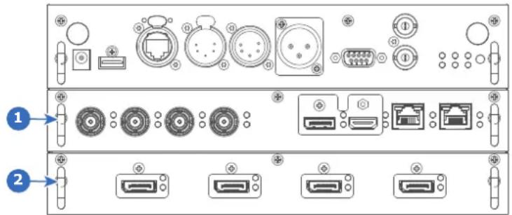
Image C-1
1 Slot L1, here filled with the Quad combo Input board
2 Slot L2, here filled with the Quad DP 1.2 Input board
C.2 DMX chart, Basic
Overview
| Ch. | Function Value | Default Action | ||
| 1 | Shutter + Intensity 0 | -7 255 Close shutter | ||
| 8 - 255 | Adjust intensity | |||
| 2 | Function select | 0 - 7 | 0 No function | |
| 8 - 15 | Activate first profile preset (If held for 1 second) | |||
| 16 - 23 | Activate second profile preset (If held for 1 second) | |||
| 24 - 31 | Activate third profile preset (If held for 1 second) | |||
| 32 - 39 | Activate fourth profile preset (If held for 1 second) | |||
| 40 - 47 | Activate fifth profile preset (If held for 1 second) | |||
| 48 - 55 | Activate sixth profile preset (If held for 1 second) | |||
| 56 - 63 | Activate seventh profile preset (If held for 1 second) | |||
| 64 - 71 | Activate eighth profile preset (If held for 1 second) | |||
| 72 - 79 | Activate ninth profile preset (If held for 1 second) | |||
| 80 - 87 | Activate tenth profile preset (If held for 1 second) | |||
| 88 - 95 | Select input 1: HDMI Input (If held for 1 ^18 second) | |||
| 96 - 103 | Select input 2: DisplayPort Input (If held for 1 second) _18 | |||
| 104 - 111 | Select input 3: SDI Input A (If held for 1 ^18 second) | |||
| 112 - 119 | Select input 4: SDI Input B (If held for 1 ^18 second) | |||
| 120 - 127 | Select input 5: HDBaseT Input 1 (if held for 1 second) _18 | |||
| 128 - 135 | Select input 6: Quad SDI input (if held for 1 ^18 second) | |||
| 136 - 143 | Select input | 7: Quad DP board Input A (if held for 1 second) ^19 | ||
| 144 - 151 | Select input | 8: Quad DP board Input B (if held for 1 second) ^19 | ||
| 152 - 159 | Select input | 9: Quad DP board Input C (if held for 1 second) ^19 | ||
| 160 - 167 | Select input | 10: Quad DP board Input D (if held for 1 second) ^19 | ||
| 168 - 175 | Select input | 11: Quad DP board Inputs A-B (if held for 1 second) ^19 | ||
| 176 - 183 | Select input | 12: Quad DP board quad column mode (if held for 1 second) | ||
| 184 - 207 | Reserved for Power on / Power down Reserved for | future functionality | ||
| 208 - 115 | Light source on (If held for 5 seconds) | |||
| 216 - 223 | / Light source off (if held for 5 seconds) | |||
| 224 - 255 | future functionality |
C.3 DMX chart, Extended
Overview
| Ch. | Function Value Default Actions | |||
| 1 | Shutter + Intensity | 0 - 7 | 255 | Close shutter |
| 8 - 255 | Adjust intensity | |||
| 2 | Brightness | 0 - 255 | 128 | Adjusts the brightness between 0 and 100% on input. |
| 3 | Contrast | 0 - 255 | 128 | Adjusts the contrast between 0 and 100% on input |
| 4 | Input selection | 0 - 7 | 0 No | function |
| 8 - 15 | Activate first profile preset (If held for 1 second) | |||
| 16 - 23 | Activate second profile preset (If held for 1 second) | |||
| 24 - 31 | Activate third profile preset (If held for 1 second) | |||
| 32 - 39 | Activate fourth profile preset (If held for 1 second) | |||
| 40 - 47 | Activate fifth profile preset (If held for 1 second) | |||
| 48 - 55 | Activate sixth profile preset (If held for 1 second) | |||
| 56 - 63 | Activate seventh profile preset (If held for 1 second) | |||
| 64 - 71 | Activate eighth profile preset (If held for 1 second) | |||
| 72 - 79 | Activate ninth profile preset (If held for 1 second) | |||
| 80 - 87 | Activate tenth profile preset (If held for 1 second) | |||
| 88 - 95 | Select input 1: HDMI Input (If held for 1 second) | |||
| 96 - 103 | Select input 2: DisplayPort Input (If held for 1 second) | |||
| 104 - 111 | Select input 3: SDI Input A (If held for 1 second) | |||
| 112 - 119 | Select input 4: SDI Input B (If held for 1 second) | |||
| 120 - 127 | Select input | 5: HDBaseT Input 1 (if held for 1 second) | ||
| Ch. | Function Value | Default Actions | ||
| 128 - 135 | Select input | 6: Quad SDI input (if held for 1 second) ^18 | ||
| 136 - 143 | Select input | 7: Quad DP board Input A (if held for 1 second) ^19 | ||
| 144 - 151 | Select input | 8: Quad DP board Input B (if held for 1 second) ^19 | ||
| 152 - 159 | Select input | 9: Quad DP board Input C (if held for 1 second) ^19 | ||
| 160 - 167 | Select input | 10: Quad DP board Input D (if held for 1 second) ^19 | ||
| 168 - 175 | Select input | 11: Quad DP board Inputs A-B (if held for 1 second) ^19 | ||
| 176 - 183 | Select input | 12: Quad DP board quad column mode (if held for 1 secori ^8 ) | ||
| 184 - 255 | Reserved for | future functionality | ||
| 5 Focus (MSB) 0 - 255 | 128 Set coarse lens focus adjustment ^20 | |||
| 6 Focus (LSB) 0 - 255 | 128 Set fine lens focus adjustment ^20 | |||
| 7 Zoom (MSB) 0 - 255 | 128 Set coarse lens zoom adjustment ^20 | |||
| 8 Zoom (LSB) | 0 - 255 128 Set fine lens zoom adjustment ^20 | |||
| 9 Lens shift vertical (MSB) | 0 - 255 128 Set coarse lens shift in vertical direction | |||
| 10 Lens shift vertical (LSB) | 0 - 255 128 Set fine lens shift in vertical direction | |||
| 11 Lens shift horizontal (MSB) | 0 - 255 128 Set coarse lens shift in horizontal direction | |||
| 12 Lens shift horizontal (LSB) | 0 - 255 128 Set fine lens shift in horizontal direction | |||
| 13 Light Source Power ^21 | 0 | 0 Set light source to 100% | ||
| 1 - 61 | ||||
| 64 | ||||
| 67 | ||||
| 70 | ||||
| 73 | ||||
| 76 | ||||
| 79 | ||||
| 80 - 87 | ||||
| 88- 95 | ||||
| 96 - 255 | ||||
| 14 Various | 0 - 7 | 0 | Reserved for future functionality | |
| 8 - 15 | Calibrate lens zoom & focus (if held for 5 seconds) | |||
| 16 - 23 | Calibrate lens horizontal and vertical shift (if held for 5 seconds) | |||
| 24 - 31 | Calibrate lensReserved for | (zoom, focus and shift) (if held for 5 seconds) | ||
| 32 - 255 | future functionality | |||
Regulatory information
D
D.1 Product compliance 216
D.2 China RoHS compliance 217
D.3 Taiwan RoHS compliance....218
D.4 Turkey RoHS compliance....219
D.5 Disposal information 219
D.6 Contact information....220
D.7 Production address....220
D.1 Product compliance
UK Compliance

This product is fit for use in the UK.
Authorised Representative: Barco UK Ltd
Address: Building 329, Doncastle Road
Bracknell RG12 8PE, Berkshire, United Kingdom
EurAsian Conformity (EAC)

This product complies with the Safety of Low-Voltage Equipment (LVE Technical Regulation 004/2011, CU TR 004/2011) and the Electromagnetic Compatibility of Technical Products (EMC Technical regulation, CU TR 020/2011)
Federal Communications Commission (FCC Statement)
This equipment has been tested and found to comply with the limits for a class A digital device, pursuant to Part 15 of the FCC rules. These limits are designed to provide reasonable protection against harmful interference when the equipment is operated in a commercial environment. This equipment generates, uses, and can radiate radio frequency energy and, if not installed and used in accordance with the instruction manual, may cause harmful interference to radio communications. Operation of this equipment in a residential area may cause harmful interference, in which case the user will be responsible for correcting any interference at his own expense
Changes or modifications not expressly approved by the party responsible for compliance could void the user's authority to operate the equipment
FCC responsible: Barco Inc.
3059 Premiere Parkway Suite 400
30097 Duluth GA, United States
Tel: +1 678 475 8000
EMC notices
EN55032/CISPR32 Class A MME (MultiMedia Equipment)
Warning : This equipment is compliant with Class A of CISPR 32. In a residential environment this equipment may cause radio interference.
BSMI Taiwan Class A statement:
D.2 China RoHS compliance
中国大陆 RoHS (Information for China ROHS compliance)
According to the “Management Methods for the Restriction of the Use of Hazardous Substances in Electrical and Electronic Products” (Also called RoHS of Chinese Mainland), the table below lists the names and contents of toxic and/or hazardous substances that Barco’s product may contain. The RoHS of Chinese Mainland is included in the MCV standard of the Ministry of Information Industry of China, in the section “Limit Requirements of toxic substances in Electronic Information Products”.
| 零件项目(名称)Component name | 有毒有害物质或元素Hazardous substances and elements | |||||
| 铅(Pb) | 汞(Hg) | 镉(Cd) | 六价铬(Cr6+) | 多溴联苯(PBB) | 多溴二苯醚(PBDE) | |
| 印制电路配件Printed Circuit Assemblies | X O | O O O | O | |||
| 外接电(线)缆External cables | X O | O O O | O | |||
| 内部线路Internal wiring | X O | O O O | O | |||
| 镜头支架Lens holder | X O | O O O | O | |||
| 光学镜头Optical lenses | X O | O O O | O | |||
| 螺帽,螺钉(栓),螺旋(钉),垫圈,紧固件Nuts, bolts, screws, washers, fasteners | X O | O O O | O | |||
| 激光发生器Laser | X O | O O O | O | |||
| 电源供应器Power Supply Unit | X O | O O O | O | |||
| 风扇Fan | X | O O | O O O | |||
| 附電池遥控器Remote control | X O | O O O | O | |||
| 泵Pump | X O | O O O | O | |||
| 本表格依据SJ/T 11364的规定编制This table is prepared in accordance with the provisions of SJ/T 11364.O:表示该有毒有害物质在该部件所有均质材料中的含量均在 GB/T 26572 标准规定的限量要求以下.O:Indicates that this toxic or hazardous substance contained in all of the homogeneous materials for this part is below the limit requirement in GB/T 26572.X:表示该有毒有害物质至少在该部件的某一均质材料中的含量超出 GB/T 26572 标准规定的限量要求.X:Indicates that this toxic or hazardous substance contained in at least one of the homogeneous materials used for this part is above the limit requirement in GB/T 26572. | ||||||

All Electronic Information Products (EIP) that are sold within Chinese Mainland must comply with the “Marking for the restriction of the use of hazardous substances in electrical and electronic product” of Chinese Mainland, marked with the Environmental Friendly Use Period (EFUP) logo. The number inside the EFUP logo that Barco uses (please refer to the photo) is based on the “General guidelines of environment-friendly use period of electronic information products” of Chinese Mainland.
D.3 Taiwan RoHS compliance
限用物質含有情況標示聲明書 (Declaration of the Presence Condition of the Restricted Substances Marking)
| 設備名稱: 投影機, 型號(型式): UDXEquipment name: Projector, Type designation: UDX | ||||||
| 限用物質及其化學符號Restricted substances and its chemical symbols | ||||||
| 單元Unit | 鉛Lead(Pb) | 汞Mercury(Hg) | 鎘Cadmium(Cd) | 六價鉻Hexavalentchromium(Cr6+) | 多溴聯苯Polybrominatedbiphenyls(PBB) | 多溴二苯醚Polybrominateddiphenylethers(PBDE) |
| 印製電路板配件Printed Circuit Assemblies | - | ○ | ○ ○ ○ | ○ | ||
| 外接電(線)纜External cables | - | ○ | ○ ○ ○ | ○ | ||
| 內部線路Internal wiring | - | ○ | ○ ○ ○ | ○ | ||
| 光學鏡頭Optical lenses | - | ○ | ○ ○ ○ | ○ | ||
| 鏡頭支架Lens holder | - | ○ | ○ ○ ○ | ○ | ||
| 螺帽, 螺釘(栓), 螺旋(釘), 塊圈, 緊固件Nuts, bolts, screws, washers, fasteners | - | ○ | ○ ○ ○ | ○ | ||
| 激光發生器Laser | - | ○ | ○ ○ ○ | ○ | ||
| 電源供應器Power Supply Unit | - | ○ | ○ ○ ○ | ○ | ||
| 風扇Fan | - | ○ | ○ ○ ○ | ○ | ||
| 遙控器Remote Control | - | ○ | ○ ○ ○ | ○ | ||
| 泵Pump | — | ○ | ○ ○ | ○ | ||
| 備考1. “超出0.1 wt %”及“超出0.01 wt %”係指限用物質之百分比含量超出百分比含量基準值。Note 1: “Exceeding 0.1 wt %” and “exceeding 0.01 wt %” indicate that the percentage content of the restricted substance exceeds the reference percentage value of presence condition.備考2. “○”係指該項限用物質之百分比含量未超出百分比含量基準值。Note 2: “○” indicates that the percentage content of the restricted substance does not exceed the percentage of reference value of presence.備考3. “—”係指該項限用物質為排除項目。Note 3: The “—” indicates that the restricted substance corresponds to the exemption. | ||||||
D.4 Turkey RoHS compliance
Turkey RoHS compliance
[Republic of Turkey: In conformity with the WEEE Regulation]
D.5 Disposal information
Disposal Information
Waste Electrical and Electronic Equipment (WEEE)
This symbol on the product indicates that, under the European Directive 2012/19/EU governing waste from electrical and electronic equipment, this product must not be disposed of with other municipal waste. Please dispose of your waste equipment by handing it over to a designated collection point for the recycling of waste electrical and electronic equipment. To prevent possible harm to the environment or human health from uncontrolled waste disposal, please separate these items from other types of waste and recycle them responsibly to promote the sustainable reuse of material resources.
For more information about recycling of this product, please contact your local city office or your municipal waste disposal service. For details, please visit the Barco website at: http://www.barco.com/AboutBarco/weee
Disposal of batteries in the product

This product contains batteries covered by the Directive 2006/66/EC which must be collected and disposed of separately from municipal waste.
If the battery contains more than the specified values of lead (Pb), mercury (Hg) or cadmium (Cd), these chemical symbols will appear below the crossed-out wheeled bin symbol.
By participating in separate collection of batteries, you will help to ensure proper disposal and to prevent potential negative effects on the environment and human health.
D.6 Contact information
Barco contact information
Registered office address: President Kennedypark 35, 8500 Kortrijk, Belgium
Contact address: Beneluxpark 21, 8500 Kortrijk, Belgium
Importers contact information
To find your local importer, contact Barco directly or one of Barco's regional offices via the contact information given on Barco's web site, www.barco.com.
D.7 Production address
Factories
Barco NV (BELGIUM)
President Kennedypark 35, B-8500 Kortrijk
CFG Barco (Beijing) Electronics Co., Ltd.
中影巴可(北京)电子有限公司*
No. 16, Changsheng Road Changping Park, Changping District, 102200, Beijing, P.R.C
The made in country is indicated on the product ID label on the product itself.
Production date
The month and year of production is indicated on the product ID label on the product itself.
WiFi & GSM compliance information
E
E.1 Compliance FCC 222
E.2 Compliance IC....222
E.3 KCC Certification....223
About this chapter
This chapter contains important compliance information related to the WiFi and GSM module.

Regulatory information for US and Canada can be accessed in the OSD of the projector. In order access it, select System Settings → Regulatory Information → Country.
E.1 Compliance FCC
Federal Communication Commission Interference Statement
You are cautioned that changes or modifications not expressly approved by the part responsible for compliance could void the user's authority to operate the equipment.
This equipment has been tested and found to comply with the limits for a Class A digital device, pursuant to Part 15 of the FCC rules. These limits are designed to provide reasonable protection against harmful interference in a residential installation. This equipment generates, uses and can radiate radio frequency energy and, if not installed and used in accordance with the instructions, may cause harmful interference to radio communications. However, there is no guarantee that interference will not occur in a particular installation.
If this equipment does cause harmful interference to radio or television reception, which can be determined by turning the equipment off and on, the user is encouraged to try to correct the interference by one or more of the following measures:
- Reorient or relocate the receiving antenna.
- Increase the separation between the equipment and receiver.
- Connect the equipment into an outlet on a circuit different from that to which the receiver is connected.
- Consult the dealer or an experienced radio/TV technician for help.
This device complies with Part 15 of the FCC Rules. Operation is subject to the following two conditions:
- This device may not cause harmful interference, and
- This device must accept any interference received, including interference that may cause undesired operation of the device.
FCC RF Radiation Exposure Statement:
- This Transmitter must not be co-located or operating in conjunction with any other antenna or transmitter.
- This equipment complies with RF radiation exposure limits set forth for an uncontrolled environment. This equipment should be installed and operated with a minimum distance of 20 cm between the radiator and your body.
E.2 Compliance IC
Radio Frequency (RF) exposure information
This equipment (IC 23575-R8767900X) complies with IC radiation exposure limits set forth for an uncontrolled environment.
This equipment should be installed and operated with a minimum distance of 20 centimeters between the radiator and your body.
Industry Canada statement
This device complies with Industry Canada's license-exempt RSSs
Operation is subject to the following two conditions:
- this device may not cause interference, and
- this device must accept any interference, including interference that may cause undesired operation of the device.
Operation in the band 5150-5250 MHz is only for indoor use to reduce the potential for harmful interference to co-channel mobile satellite systems. For the frequency 5600-5650 MHz, no operation is permitted".
Industry Canada class A emission compliance statement
This equipment has been tested and found to comply with the limits for a Class A digital device, pursuant to Canadian ICES-003.
These limits are designed to provide reasonable protection against harmful interference when the equipment is operated in a commercial environment. This equipment generates, uses, and can radiate radio frequency
energy and, if not installed and used in accordance with the instruction manual, may cause harmful interference to radio communications. Operation of this equipment in a residential area is likely to cause harmful interference in which case the user will be required to correct the interference at his own expense.
E.3 KCC Certification
KCC 인증

모듈 ID: KCC-CRM-TCS-HE910-D
제조연월: 2019.
A router that serves as an entry point into and exit point out of a network. For example, a local network (LAN) may need a gateway to connect it to a wide area network (WAN) or to the Internet.
DHCP
Dynamic host configuration protocol. DHCP is a communications protocol that lets network administrators manage centrally and automate the assignment of IP addresses in an organization's network. Using the Internet Protocol, each machine that can connect to the Internet needs a unique IP address. When an organization sets up its computer users with a connection to the Internet, an IP address must be assigned to each machine. Without DHCP, the IP address must be entered manually at each computer and, if computers move to another location in another part of the network, a new IP address must be entered. DHCP lets a network administrator supervise and distribute IP addresses from a central point and automatically sends a new IP address when a computer is plugged into a different place in the network.
DMX
DMX-512 Lighting protocol over RS-485 interface. Carries information of 512 channels from a lighting controller to lighting devices. Standardized by USITT.
HD
Hazard Distance (HD) is the distance measured from the projection lens at which the intensity or the energy per surface unit becomes lower than the applicable exposure limit on the cornea or on the skin. The light beam is considered (to be) unsafe for exposure if the distance from a person to the light source is less than the HD.
IP
Internet Protocol. The network layer of TCP/IP. Required for communication with the internet.
Latency
The total time from the first pixel is coming in on an input source, until the first light representing that pixel is visible on the screen. This includes the transport delay. The value is normally given in milliseconds.
MAC address
Media Access Control address. Unique hardware number, used in combination with the IP-address to connect to the network (LAN or WAN).
RS232
An Electronic Industries Association (EIA) serial digital interface standard specifying the characteristics of the communication path between two devices using either D-SUB 9 pins or D-SUB 25 pins connectors. This standard is used for relatively short-range communications and does not specify balanced control lines. RS-232 is a serial control standard with a set number of conductors, data rate, word length and type of connector to be used. The standard specifies component connection standards with regard to computer interface. It is also called RS-232-C, which is the third version of the RS-232 standard, and is functionally identical to the CCITT V.24 standard. Logical '0' is > + 3V, Logical '1' is < - 3V. The range between -3V and +3V is the transition zone.
RS422
An EIA serial digital interface standard that specifies the electrical characteristics of balanced (differential) voltage, digital interface circuits. This standard is usable over longer distances than RS-232. This signal governs the asynchronous transmission of computer data at speeds of up to 920,000 bits per second. It is also used as the serial port standard for Macintosh computers. When the difference between the 2 lines is < - 0.2V that equals with a logical '0'. When the difference is > +0.2V that equals to a logical '1'.
Subnet mask
A number that is used to identify a subnetwork so that IP addresses can be shared on a local area network.
Transport latency
The added delay in the image processing chain. The value is the number of lines relative to the output resolution.
List of tools
Clean cotton cloth
Clean micro fiber lens cleaning cloth (e.g. Toraysee® cloth(s))
Compressed air
Lens cleaner (e.g. ZEISS lens cleaner, Purosol™ or other water based lens cleaner products)
Level
Index
Numbers/Symbols
3D emitter
setup 115
3D projection 113
3D setup 114
A
Active 3D 113
setup 115
Active Stereo 113
Address
Program
RCU 36
Alignment
Warping 89
4 Corners 93
Bow 95
Files 99
Latency Control 101
On/Off 90
Screen Size 90
B
Backlight
Control 141
LCD Display 141
Battery
Disposal 220
Blending 102
Basic blend 103, 105
Black level adjustment 108
Files 111
RGB adjustment 110
Black Level Files 111
Blend Files 107
Blend mask 105
Blend Zones 105
Masking 105
RGB adjustment 110
RGB gain 110
Brightness 64
C
CE Certification 20
Cleaning
Exterior 174
Lens 173
Communication 39
DMX 42
Introduction 40
IR control
Broadcast address 124
IR sensors 125
Projector address 124
Remote control
Broadcast address 124
Projector address 124
RS232 42
RS422 42
USB port 43
Communication panel 42
Compliance 21
GSM 221
Product 216
WiFi 221
Compliance FCC 222
Compliance IC 222
Connect
Source 26
Connection possibilities 114
Contact address 220
Contact information 220
Contrast 64
Convergence 153
Cooling liquid circuit warning 13
Custom projector name 126
D
Digital Shift 69
Digital Zoom 69
Display
Multiple sources 58
Single source 58
DisplayPort 1.2 inputs
Specifications 195
Disposal 219
Battery 220
DMX 135
DMX chart 209
Basic 210
Extended 211
DMX Chart
Input mapping 210
DMX input 42
DMX interface 42
DMX out 42
Download
Product manual 21
E
Electronic Convergence 153
Enclosed projection 18
Environmental information
Disposal information 219
RoHS compliance
China 217
Taiwan 218
Turkey 219
Ethernet connection 127
IP address, wired connection 128
IP address, wireless connection 130
EurAsian Conformity (EAC) 216
Exclusion zone 12
Exterior
Cleaning 174
External cooler 154
F
Fiber
Input 48
SFP 48
Flex brightness 151
Flight case
Safety 15
Focus 80
Function
Button pressed indicator 35
G
Gamma correction 66
Gamma type
DICOM 67
sRGB 67
General considerations 10
Getting started 23
Graphic User Interface
Overview 50
Graphics User Interface 49
GSM
Compliance 221
GSM activation
SIM card 138
GUI
Image 63
Installation 79
Introduction 49
Navigation 53
Overview 50
Test Patterns 55
H
Hazard Distance 16, 18
Modifying optics 20
Hazardous Chemicals 15
HDBaseT inputs
Specifications 194
HDBaseT ^TM connection
IP address, wired connection 133
HDMI inputs
Specifications 194
High Brightness precautions 16
Host name 126
|
Illumination 112
Image
DynaBlack 77
Dynamic contrast 77
Gamma 66–67
HDR 76
Perceptual Quantizer 76
PQ 76
Sharpness 65
Image projection 26
Importer 220
Input 39
Fiber 48
Introduction 40
Quad Combo Mk I 46
Quad Combo Mk II 45
Quad DP 1.2 47
SFP 48
Small Form-factor Pluggable 48
Input & Communication
Terminology overview 40
Introduction
GUI 49
IR control
Broadcast address 124
IR sensors 125
Projector address 124
K
KCC Certification 223
KCC 인증 223
L
Laser Banks
Status 164
Laser range finder 84
Laser ranging 84
LED behavior
Quad Combo Mk I 46
Quad Combo Mk II 45
Quad DP 1.2 47
SFP 48
Lens
Adjustment
Calibration 149
Cleaning 173
Dynamic focus 81
Focus 80
Focus drift compensation 81
Shift 80
Shift to center 82
Tilt sensor 83
Zoom 80
Lens adjustment
Calibration 149
Lens features 145
Lens shift 80
Local keypad
Functionality overview 40
M
Macro 117
Delete 121
Edit 120
New 118
Preset 120
Maintenance 171
Masking 102
Measuring system 140
mini-jack
RCU 37
Mobile activation
SIM card 138
Motorized frame
XLR connector 137
Multiple sources
Display 58
N
Network
Introduction 127
Network connection 127
IP address, wired connection 128
IP address, wireless connection 130
Notice on laser radiation
Laser radiation 11
Notice on optical radiation
Optical radiation 10
Notice on safety 10
0
Open source licenses 156
Orientation 87
Output resolution 75
Overview video timings 200
P
P7
RealColor 73
Passive 3D 113
Passive stereo 113
Power off 29
Power on 25
Prevent
Electrical shock 12
Product safety labels 16
Production address 220
Profile 117
Delete 121
New 118
Profiles
Edit 120
Preset 120
Projector
Components 24
Projector control
DMX 135
Network
Introduction 127
XLR connector 137
Projector Profile 117
Pulse
RCU 31
Remote Control Unit 31
Pulse RCU
battery 32
Functionality overview 35
on/off button 33
protection sleeve 37
Protocol setup 33
RGB button 36
RGB filter 36
Q
Quad Combo Mk I
Introduction 46
LED behavior 46
Quad Combo Mk II
Introduction 45
LED behavior 45
Quad DP 1.2
Introduction 47
LED behavior 47
R
RCU
Address 36
mini-jack 37
Use 34
XLR 36
Ready mode 29
RealColor
P7 73
Rear projection 18
Registered office 220
Regulatory information 215
Remote access
Camera preview 161
Source preview 160
Remote control
Broadcast address 124
Projector address 124
Reset
3D settings 146
All 146
Blending 146
DMX 146
Features 146
Illumination 146
Image 146
Network settings 146
Optics 146
Orientation 146
Other 146
Projector Profiles 146
Test Patterns 146
User Interface 146
User Interface settings 146
Warping 146
Restricted access location 11
Restriction zone 12
Rigging frame 85
Center position 87
RS232 42
RS422 42
S
Safety 9
Battery explosion 14
Cooling liquid circuit 13
Electrical shock 12
Fire hazard 13
Hazard Distance 16, 18
Hazardous Chemicals 15
Important instructions 12
Personal injury 12
Projector damage 14
Safety Data Sheet (SDS) 15
Servicing 15
Safety Data Sheet (SDS) 15
Safety training 11
Saturation 64
Scaling modes 88
SDI inputs
Specifications 193
Serial communication 42
Service
Convergence 153
Electronic Convergence 153
Settings
Capture mode 155
Date and time
Automatically 142
Manually 141
General
Open source licenses 156
SFP
Introduction 48
LED behavior 48
SFP inputs
Specifications 197
SIM card
Blocked 138
Single source
Display 58
Software update 172
Solarization
Capture mode 155
Remove 155
Source 57
Connect 26
Connector Settings 60
Fiber 48
SFP 48
Single source 58
Small Form-factor Pluggable 48
Specifications 175
DisplayPort 1.2 inputs 195
HDBaseT inputs 194
HDMI inputs 194
SDI inputs 193
SFP inputs 197
UDX-4K22 180
UDX-4K26 179
UDX-4K32 177
UDX-4K40 176
UDX-U32 191
UDX-U40 190
UDX-U45LC 188
UDX-W22 187
UDX-W26 185
UDX-W32 184
UDX-W40 182
Standard source files 199
Standby mode 29
Start
Image projection 26
Status Light 44
Status menu 167
Overview 168
Stealth mode 141
Stitched layouts 58
Switching off 29
Switching on 25
Switching to ready mode 29
Switching to standby mode 29
System settings
Advanced settings
Login 156
Language 139
User interface
language 139
System Settings 123, 139
Advanced settings 159
Advanced Settings
Color 162
Statistics 163
Communication 127
IP address, HDBase™ 133
IP address, wired connection 128
IP address, wireless connection 130
Factory reset 146
Flex brightness 151
Frame 152
Frame Calibration 152
Lens adjustment
Calibration 149
Lens features 145
Maintenance 159
Network 127
Power settings
Standby mode 144
Service 159
Standby mode
Power settings 144
Units
Distance 140
Temperature 140
X
XLR
RCU 36
XLR connector
Control 137
Z
Zoom 80
T
Test Patterns 55
Themes 139
Tilt sensor
Calibration 165
Touch panel 41
Turkey RoHS 219
U
UK Compliance 21, 216
Units 140
USB port 43
User definition 11
V
Video timings
DisplayPort Inputs 204
HDBaseT Inputs 206
HDMI Inputs 202
Video Timings
SDI Inputs 201
W
Warnings
Cooling liquid circuit 13
Warping 89
WEEE 219-220
WiFi
Compliance 221

- Product revision
- Copyright ©
- Changes
- Trademarks
- Product Security Incident Response
- Patent protection
- Guarantee and Compensation
- Disclaimer on GUI images used in this manual
- Disclaimer for camera usage
- Disclaimer for network usage
- Table of contents
- Safety information 9
- Getting started 23
- Pulse Remote Control Unit 31
- Input & Communication 39
- GUI – Introduction......49
- GUI – Source 57
- GUI – Image 63
- GUI – Installation 79
- GUI – Projector profiles 117
- GUI – System Settings 123
- Advanced Settings 159
- GUI – Status menu.... 167
- Projector maintenance 171
- A Specifications 175
- B Video timing tables....199
- C DMX chart 209
- D Regulatory information 215
- E WiFi & GSM compliance information 221
- Glossary 225
- List of tools 227
- Index 229
- Safety information
- 1
- About this document
- Clarification of the term "UDX" used in this document
- Model certification name
- General considerations
- General safety instructions
- Notice on safety
- Notice on optical radiation
- Notice on laser radiation
- Users definition
- Safety training to be provided by the installer
- Restricted access location
- Exclusion zone
- Restriction zone
- Important safety instructions
- To prevent the risk of electrical shock
- To prevent personal injury
- To prevent fire hazard
- To prevent battery explosion
- To prevent projector damage
- On servicing
- Malfunction unit
- Stacking/transporting UDX rental flight cases
- Safety Data Sheets for Hazardous Chemicals
- Product safety labels
- High Brightness precautions: Hazard Distance
- HD
- Restriction Zone (RZ) based on the HD
- USA market
- HD for fully enclosed projection systems
- HD in function of modifying optics
- Radio equipment (optional)
- CE Conformity
- Compliance
- UK Compliance
- Download Product Manual
- Download Product Manual
- Getting started 2
- About this chapter
- Getting to know the projector
- Orientation convention
- Projector airflow
- Projector Infra Red receivers and Remote Control Unit
- Power on projector
- How to power on
- Start image projection
- Connect the source
- Select the source
- Quick test pattern selection
- Switching to ready mode
- How to switch to ready mode
- Power off projector
- How to power off
- Pulse Remote Control Unit
- 3
- Pulse RCU, battery installation
- Where to find the batteries for the remote control ?
- How to install
- Pulse RCU, protocol setup
- About the used protocol
- Which protocol to use
- How to set
- Remarks when using the RC5 protocol
- Pulse RCU, function of the on/off button
- Function of the remote control on/off button
- Using the RCU
- Pointing to the reflective screen or IR sensors
- Using the RCU in combination with a 3D emitter
- Pulse RCU, Functionality overview
- Pulse RCU, function of the “button pressed indicator”
- Functions button pressed indicator
- Pulse RCU, function of the "RGB filter" button
- Filtering the color of the projected image
- Displaying and Programming addresses into the RCU
- Displaying the Projector Address on the Screen.
- How to Program an Address into the RCU?
- Using the XLR connector of the RCU
- How to use the XLR connector
- Using the mini-jack connector of the RCU
- How to use the mini-jack connector
- Pulse RCU, silicone protection sleeve (optional)
- Introduction
- Input & Communication
- 4
- Introduction
- General
- Local Keypad and LCD panel
- Local Keypad
- LCD panel
- LCD touch panel
- LCD touch panel functionality
- Communication connections
- Communication Panel
- V output
- DMX interface
- DMX
- RS232/RS422 input
- RS232
- RS422
- USB port
- LED and Button indication chart
- Pulse Quad Combo input Mk II
- Overview Quad Combo Input Mk II
- Functionality of the Quad Combo input Mk II
- SDI input & output - How does it work?
- LED behavior
- Pulse Quad Combo input Mk I
- Remark concerning the Mk I and Mk II inputs boards
- Visual difference between the Mk I and Mk II input boards
- Pulse Quad DP 1.2 input
- Quad DP 1.2 input
- Pulse SFP input
- Overview SFP input
- Use cases
- GUI - Introduction
- 5
- Overview
- GUI - First start of the software
- GUI - Product Registration
- GUI - Status Screens
- GUI - Main Menu overview
- Navigation
- Define values
- Using the LCD touch display
- Menu memory
- Test Patterns
- List of standard test patterns
- About the test pattern types
- How to use test patterns
- GUI - Source
- 6
- About the Source menu
- Displaying a single source
- About selecting a source
- How to select?
- Displaying multiple sources: Stitched layouts
- About stitched layouts
- How to select a stitched layout
- Connector Settings
- About Connector Settings
- How to configure a connector
- Press OK.
- Select the desired connector.
- GUI - Image 7
- Setting image levels manually
- Purpose
- How to set up Contrast
- How to set up Brightness Level
- How to set up Saturation Level
- Adjusting the sharpness
- About adjusting the sharpness
- How to adjust
- Adjusting the gamma correction
- About gamma correction
- Setting the desired Gamma type
- About the alternate gamma types
- Exception when using an HDR source
- How to adjust the gamma type?
- Digital Shift & Zoom
- What can be done?
- The effect of Digital Zoom
- The effect of Digital Shift
- Digital Shift & Zoom
- RealColor P7
- How to set custom P7 values
- How to choose one of the P7 presets
- Setting the output resolution
- How to determine the desired output resolution for my content
- How to choose the output resolution
- Select the desired output resolution.
- Displaying HDR content
- About HDR and PQ
- When do I know my content is HDR encoded?
- How to properly display HDR content?
- How to set the HDR-related parameters?
- Dynamic contrast
- About dynamic contrast
- How to set the dynamic contrast?
- GUI - Installation
- 8
- Configuring the lens, optical zoom-focus
- Zoom - Focus
- Configuring the lens, shift
- Vertical and Horizontal Shift
- Configuring the lens, dynamic focus
- About focus drift and dynamic focus
- How to enable dynamic focus?
- Configuring the lens, Shift to center
- How force lens in Mid position
- Configuring the lens, tilt sensor
- When to use the tilt sensor menu
- How to read the tilt sensor values
- Laser ranging
- How to manipulate the laser range finder?
- Manipulating the rigging frame
- When can you manipulate the rigging frame?
- How to manipulate the rigging frame?
- Manipulating the rigging frame, center position
- Orientation
- How to set the correct orientation
- Scaling modes
- About scaling modes
- Setting a scaling mode
- Warping
- About warping
- Warping - On/Off
- About warping on/off
- How to toggle
- Warping - Screen Size
- About (Warp) Screen Size adjustment
- Using the screen aspect ratio presets
- Click Apply.
- How to adjust the image with pixels?
- Click Apply.
- Warping - 4 corners adjustment
- About 4 Corners adjustment
- How to adjust the image?
- Warping - Bow
- About bow adjustment
- Symmetric bow correction
- Asymmetric bow correction
- Warping - Warp files
- About custom Warp Files
- How to activate an uploaded Warp grid?
- Warping - Latency control in a multi projector setup
- Transport latency
- Latency
- Functional description
- How to configure transport delay?
- Blending & masking
- About blending
- Waiting period and blend maintenance period
- Basic blend
- Blend & Blend mask
- About masking and blending width or height
- How to set up basic blend zones?
- Example of the use of blending
- Blend Files
- About custom Blend Files
- How to activate an uploaded Blend configuration file?
- Basic black level adjustment
- About adjusting the black level
- How to adjust the black level manually
- RGB gain adjustment
- About RGB gain adjustment
- How to perform an RGB adjustment
- Black Level Files
- About custom Black Level Files
- How to activate an uploaded Black Level adjustment file?
- Illumination
- About CLO mode
- How to reduce the power
- 3D projection
- 3D setup
- Active Stereo & Passive Stereo
- What is Passive Stereo?
- What is Active Stereo?
- Projection method used
- Setup process 3D projection
- How to setup 3D projection?
- Connection possibilities
- Connecting with the quad combo input card
- Connecting with the quad DP 1.2 Input card
- 3D Setup
- Why change the 3D setup?
- Choosing the desired output mode
- Source signal
- AutoStereo Mono ActiveStereo
- How to adjust the projector to the 3D emitter?
- GUI – Projector profiles
- 9
- About projector profiles
- Saving the current projector settings in a profile
- How to save the current projector settings?
- Assigning a created projector profile to a preset
- How to assign a projector profile to a preset
- Deleting a projector profile
- How to delete a profile
- GUI - System Settings
- 10
- Remote control
- Broadcast address
- About broadcast address
- How to the broadcast address
- Projector address
- About individual projector address
- How to change
- IR sensors
- How to disable
- Host name - custom projector name setup
- How to set a different Host name
- Communication, LAN setup
- About a network connection
- Introduction to a Network connection
- DHCP
- IP
- Subnet mask
- Default Gateway
- MAC address
- What should be set up for an Ethernet address?
- Wired IP address set up
- How to automatically set up the IP address
- How to manually set up the IP address
- Wireless IP address set up
- When can the wireless IP address be used?
- How to connect to a wireless network?
- LAN over HDBaseMIP address set up
- About LAN over HDBaseT
- DMX
- About the ways to control the projector via DMX
- How to set up DMX?
- Front XLR output voltage control
- How to enable or disable?
- GSM configuration
- When to use the GSM menu
- About the SIM card PIN code
- How to activate
- Changing the User Interface language
- Themes
- About Themes
- How to select a different interface theme
- Units (measurement) system setup
- About the measurement systems
- How to set a different metric system
- Controlling the backlight of the LCD Display
- What lighting can be controlled?
- Stealth Mode
- How to set the backlight
- Date and time setup - manually
- About date and time
- How to set manually
- Date and time setup - automatically
- To set date and time automatically
- Power saving settings – Standby mode
- Why change the power saving features?
- How to change the power saving features?
- Lens features
- How to enable/disable
- Factory reset
- Factory settings
- How to reset all projector settings
- How to reset one or more projector settings
- Lens Calibration
- How to calibrate
- Flex brightness
- Overview
- Availability
- Flex codes
- Maximum Light output setup via OSD menu
- Rigging frame Calibration
- Electronic Convergence
- How to display the convergence settings
- Setting up the external cooler on a UDX
- Using the external cooler
- How to set up the external cooler
- Capture mode
- Why use capture mode?
- How to enable Capture mode
- Login to advanced settings
- How to login
- List of open source licenses
- About open source licenses
- How to find the open source licenses
- Advanced Settings
- 11
- About the Advanced Settings menu
- Remote access – Enable source preview
- Source preview
- How to enable source preview
- Remote access – Enable camera preview
- Camera preview
- How to enable Camera preview
- Advanced Settings - Color
- How to adjust the P7 native settings
- Advanced Settings – Statistics
- What can be seen?
- How to display the statistics
- Checking the status of the Laser Banks
- About failing laser banks
- How to check the status of the Laser Banks
- Advanced settings - Tilt sensor calibration
- Required tools
- How to calibrate the tilt sensor?
- GUI - Status menu
- 12
- Status menu overview
- What can be seen on the Status page?
- What can be seen on the About page?
- Projector maintenance
- 13
- Software update
- How to update the software
- How to update the software if the projector isn't connected to the network
- Cleaning the lens
- How to clean the lens?
- Cleaning the exterior of the projector
- Specifications
- A
- A.1 Specifications of the UDX-4K40
- A.2 Specifications of the UDX-4K32
- A.3 Specifications of the UDX-4K26
- A.4 Specifications of the UDX-4K22
- A.5 Specifications of the UDX-W40
- A.6 Specifications of the UDX-W32
- A.7 Specifications of the UDX-W26
- A.8 Specifications of the UDX-W22
- A.9 Specifications of the UDX-U45LC
- A.10 Specifications of the UDX-U40
- A.11 Specifications of the UDX-U32
- A.12 Specifications SDI inputs
- A.13 Specifications HDMI inputs
- A.14 Specifications HDBaseT inputs
- A.15 Specifications DisplayPort 1.2 inputs
- A.16 Specifications SFP inputs
- Video timing tables
- B
- B.1 Overview video timings
- List of compatible signals
- B.2 Overview video timings SDI Inputs
- B.3 Overview video timings HDMI 2.0 inputs
- B.4 Overview video timings DisplayPort 1.2 inputs
- B.5 Overview video timings HDBaseT inputs
- DMX chart
- C
- C.1 DMX chart input board positioning
- About the input boards
- C.2 DMX chart, Basic
- C.3 DMX chart, Extended
- Regulatory information
- D
- D.1 Product compliance
- EurAsian Conformity (EAC)
- Federal Communications Commission (FCC Statement)
- EMC notices
- D.2 China RoHS compliance
- 中国大陆 RoHS (Information for China ROHS compliance)
- D.3 Taiwan RoHS compliance
- D.4 Turkey RoHS compliance
- Turkey RoHS compliance
- D.5 Disposal information
- Disposal Information
- Disposal of batteries in the product
- D.6 Contact information
- Barco contact information
- Importers contact information
- D.7 Production address
- Factories
- Production date
- WiFi & GSM compliance information
- E
- E.1 Compliance FCC
- Federal Communication Commission Interference Statement
- This device complies with Part 15 of the FCC Rules. Operation is subject to the following two conditions:
- FCC RF Radiation Exposure Statement:
- E.2 Compliance IC
- Radio Frequency (RF) exposure information
- Industry Canada statement
- Industry Canada class A emission compliance statement
- E.3 KCC Certification
- List of tools
- Index
- Numbers/Symbols
- F
- G
- H
- |
- K
- L
- M
- N
- 0
- P
- Q
- R
- S
- X
- Z
- T
- U
- V
- W
Brand : Barco
Model : UDX-W40
Category : Projector