
Tinker Board 2S - Media player ASUS - Free user manual and instructions
Find the device manual for free Tinker Board 2S ASUS in PDF.


| Product Type | Single-board computer / Media player |
| Processor | Rockchip RK3399 (Dual ARM Cortex-A72 + Quad ARM Cortex-A53) |
| Memory | 2GB LPDDR4 (dual-channel) |
| Storage | 16GB eMMC; microSD card slot (up to 128GB) |
| Display Output | HDMI 2.0 (up to 4K@60Hz); USB Type-C with DP alt mode |
| Audio | 3.5mm audio jack; HDMI audio output |
| Connectivity | Gigabit Ethernet; Dual-band Wi-Fi 802.11ac; Bluetooth 4.2 |
| USB Ports | 2 x USB 3.0 Type-A; 1 x USB 2.0 Type-A; 1 x USB Type-C (data/DP) |
| GPIO | 40-pin GPIO header (compatible with Raspberry Pi HATs) |
| Camera Interface | MIPI CSI-2 (15-pin) connector |
| Display Interface | MIPI DSI (15-pin) connector |
| Power Supply | 12-19V DC via barrel jack (5.5/2.5mm); 5V via GPIO pins (max 3A) |
| Power Consumption | Approximately 10-15W typical |
| Operating System | TinkerOS (Debian-based); supports Android, Armbian, Yocto |
| Dimensions | 85 x 90 mm (approx.) |
| Weight | Approximately 80 g (board only) |
| Safety Features | Over-current protection; designed for well-ventilated placement; avoid simultaneous power input from DC jack and GPIO |
| Maintenance | Keep free of dust; avoid moisture; handle by edges when powered off |
| Package Contents | Tinker Board 2S, heatsink, shielding bag, quick start guide, SATA cable (optional) |
Frequently Asked Questions - Tinker Board 2S ASUS
User questions about Tinker Board 2S ASUS
0 question about this device. Answer the ones you know or ask your own.
Ask a new question about this device
Download the instructions for your Media player in PDF format for free! Find your manual Tinker Board 2S - ASUS and take your electronic device back in hand. On this page are published all the documents necessary for the use of your device. Tinker Board 2S by ASUS.
USER MANUAL Tinker Board 2S ASUS
IN SEARCH OF INCREAS

TINKER BOARD 2 Series
Innovativels enjoy a
Enjoy innovative job incentives
Copyright © ASUGTEK Computer Inc.
1
10.00
Thank you for purchasing
ASUS Tinker Board 2 Series
Tinker Board 2 Series is more than a cream for the DIY-obsessed: it's a gateway to new ideas and new relationships. Experienced makers will love Tinker Board's performance-to-price ratio and
strong brand heritage, while novices and younger users will appreciate its accessibility and ease of use. (But all will come transfer to origin. Territory: This book)
Use your own computer to create a website.
Package contents
Check your Tinker Board 2 Series package for the following items:
1 x Tinker Board 25 or Tinker Board 2:1 x Shielding bag
Heatairik* 1 Quick start guide
- 60-FEBIT amortiva cables
Beware of high temperatures when only using the bundled heat sink.
Safety Information
Power supply used with the Tinker shall comply with relevant regulations and applicable standards.
DO NOT overrun the power, as this may cause damage to the board.
Ensure that the board is placed in a well ventilated environment.
The board should be placed on a flat, stable, non-conductive surface.
Avoid handling the board while powered. Handle the board by the edges to minimize risk of electrostatic discharge (ESD).
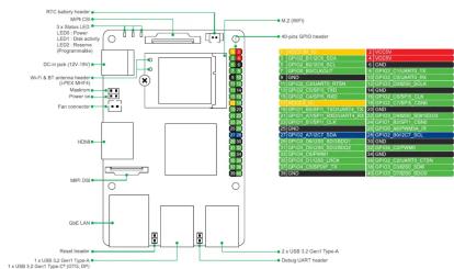
Do not use both the system DC power-in jack and the 40-pin GPIO +5V pins (pin 2 and 4, red) for power input at the same time. Please refer to the Top view illustration for the location.
If you wish to use the 40-pin GPIO +5V pins (pin 2 and 4, red) as a power input source, please make sure the power input rating for each pin complies with the standard of 5V (+/-5% deviation).
- If you wish to use the 40-pin D890 +56 /min 2 and 6, ref) as a power input source, please
Make sure the power input rating for each pin complies with the standard of 5V (+/-5% deviation).
A power rating failure that exceeds the rating value mentioned, or an unstable power source may result in damage to your system or hardware. Please refer to the Top view illustration for the location.
New illustration for the location of the girls.
ASUS Tinker Board 2 Series
specifications summary
| Table 10.2 (See Table 20) (Title and Number) | |
| Contourative Area | Suburban Area (Cov) |
| AUC | Dual Area (Cov) * ACG * 0.3 & 0.4 |
| DVA | Dual Area (Cov) * Dual Area (Cov) * 0.5 & 0.6 |
| GPA* | Area* = (180,000 gm) / GPA * 0.80 Mb |
| Display | 1 - 1400V DC (DC) + 150V DC (DC) |
| Display | 1 - 1400V Tpm* (2" × 21.1") |
| Memory Size | 1 - 250 V RPM* (25" × 25m) |
| Capacity | Dual Area (POT) * 25.4 m (× 25m2) |
| Storage | High capacity |
| Cooperative Area | Mean 3575 V, total capacity (250 V) |
| Contourative Area | 902 - 402.1 (chosphorylase, 5.87 × 10-375 cm) |
| Audio | 1 - 1400V dB* audio subunit |
| Audio | 1 - 1400V PSF (sub) video (GPs) |
| Audio | 1 - 150000000000000000000000000000000000000000000000000000000000000000000000000000000000000000000000000000 |
| Audio | 1 - 150000 dB* 1.5mm (Tpm* 250000) |
| Container Interface | 1 - 15000 MPB (150 x 12 mm) |
| 1. 4 GHz (band) (band) | |
| 1. 4 GHz (band) (band) | |
| 1. 4 - 2.5 MHz (band) | |
| 1. 4 - 2.5 MHz (band) | |
| 1. 4 - 1.5 MHz (band) | |
| 1. 4 - 1.5 MHz (band) | |
| 1. 4 - 1.5 MHz (band) | |
| Visual Channels | 2 - 2.5 GHz (band) |
| 2 - 2.5 GHz (band) | |
| 2 - 2.5 MHz (band) | |
| 2 - 2.5 MHz (band) | |
| 2 - 2.5 GHz (band) | |
| 2 - 2.5 GHz (band) | |
| 2 - 2.5 GHz (band) | |
| 2 - 2.5 GHz (band) | |
| 2 - 2.5 GHz (band) | |
| 2 - 2.5 GHz (band) | |
| 2 - 2.5 GHz (band) | |
| 2 - 2.5 GHz (Band) | |
| 2 - 2.5 GHz (Band) | |
| 2 - 2.5 GHz (Band) | |
| 2 - 2.5 GHz (Band) | |
| 2 - 2.5 GHz (Band) | |
| 2 - 2.5 GHz (Band) | |
| 2 - 2.5 GHz (Band) | |
| 2 - 2.5 GHz (Band) > 2500 MHz (band) | |
| Power Generator (up to 400W) | 1 - 150 W/Hz Power consumer (kHz 3.0–5.0 mm) |
| DSI Support | Below 1.5 GHz (≤ 1.5 GHz) |
| Total | 3.37* = 2.35* (36.4 × 16 km) |
Getting Started Top view Bottom view
Booting from external Micro SD card
Requirement:
• 1 a Micro SD card with at least 1GB capacity
• 1. a Monitor with HDMI cable or USB TwinG /DP cable
- 1 in Keyboard and Mouse-set
* The Power Supply is purchased separately.
Insert the micro-SD card into a Windows® PC
Download the TinkerOS image from the Tinker Board website (https://tinkerboard.com/10.10/10.20) and Image 8 into the mini-SD card using a mini-red-ISO
- 2017-2018: Online data security and our AI base on micro SD data using a multi-penny SSD software, such as WiDOS/Intager or Eitter;
Insert the bootable micro SD card into your Tinker Board 2S / Tinker Board 2, then connect the power supply, keyboard, mouse, and monitor to boot up.
• U.S. Treasury Notes
(6)
Z 4MBC
Required
- 1 USB Type-C® cable with data transfer for
- 1 12-19V, DC 5.5/2.5 POWER SUPPLY*
- 1 monitor with HDMI™ cable or USB Type-C® (OP) cable
The power supply is purchased separately.
Connect the Tinker Board 2S to a PC.
- Identifies a USB address but is not able to recognize the device.
Download the TinkerOS image from the Tinker Board website (https://tinker-board.asus.com/download.html) and burn it into the Tinker Board 2S using third-party software, such as Win32DiskImager or Etcher.
3. Connect the power supply, keyboard, mouse, and monitor to your Tinker Board 2S to boot up.
3 Connect the power supply, keyboard, mouse, and monitor to your linker board 2s to boot-up.
If the eMMC cannot be recognized, please refer to response at local/easia.com for more details on eMMC Recovery.
If the email can hit a recognized, please refer to response at local/easia.com for more details on eMMC Recovery.
* Only available on selected models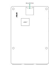
Notices
Federal Communications Commission Interference Statement
This equipment has been tested and found to comply with the limits for a Class III digital device, pursuant to part 15 of the FCC Rules. These limits are designed to provide reasonable protection
against harmful interference in a residential installation. This equipment generates, uses and can radiate radio frequency energy and, if not installed and used in accordance with the instructions,
may cause harmful interference to radio communications. However, there is no guarantee
that interference will not occur in a particular installation. If this equipment does cause harmful interference to radio or television reception, which can be determined by turning the equipment off
and on, the user is encouraged to try to correct the interference by one or more of the following measures:
- Reorient or relocate the receiving antenna.
- Increase the separation between the equipment and receiver.
- Connect the equipment to an outlet on a circuit different from that to which the receiver is connected.
- Consult the dealer or an experienced radio/TV technician for help.
•
Any changes or modifications not expressly approved by the party responsible for compliance could void the user's authority to operate the equipment.
(2)
HF exposure training This equipment must be installed and operated in accordance with provided instructions and
the antenna(s) used for this transmitter must be installed to provide a separation distance of at least 70 cm from all devices and persons, and must not be co-located or operating in conjunction with any
other antenna or transmitter. End-users and installers must be provided with antenna installation
instructions and transmitter operating conditions for satisfying RF exposure compliance.
End Product Labeling This transmitter model is authorized only for use in devices where the antenna is installed.
If the transmitter is capable of maintaining only 10 cm in a device, it may be installed such that 20 cm may be maintained between the antenna and users. The final end product must be
labeled in a visible area with the following: Contains FCC ID: TX2/RTI/WB2CF, and Contains IC: 69174/RTI/WB2CF
Table 1.6.2.3
Mexico Notice Cristina media: PDBBET18 0180
Regional notice for Singapore
This ASUS product complies with MDA Standards.
2017
Compliance Statement of Innovation, Science and Economic Development
Canada (ISED)
This device complies with Innovation, Science and Economic Development Canada licence-exempt RSS standards. Operation is subject to the following two conditions: (1) this device may
(1) This device must accept any interference, including interference that may cause undesired operation, and (2) this device must accept any interference.
that may cause undesired operation.
CAN ICES-3(0)/NMB-3(0)
NCC: Taiwan Wireless Statement
Contains module CCAT16LP2010T7
The terms HDMI, HDMI High-Definition Multimedia Interface, and the HDMI Logo are trademarks or registered trademarks of HDMI Licensing Administrator, Inc.
Registered address of HDMI Licensing Administrator, Inc.
Radio Frequency (RF) Exposure Information
The radiated output power of the Wireless Device is below the Industry Canada (IC) radio frequency exposure limits. The Wireless Device should be used in such a manner that the
potential for human contact during normal operation is minimized.
This device has also been evaluated and shown compliant with the IC RF Exposure limits under mobile accessory conditions. Carriers are also greater than 200ms from a person's body.
Information concerning exposure to radio frequency (RF).
Responsible Party: Asia Computer International
Address: 48728 Kato Rd, Fremont, CA 94508
Phone/Fax No: (518)739-3773/(518)608-4555
Bobby Environc tan 40 pectos
Product Name: MOTHERBOARD
Model Number: TINKER BOARD 2, TINKER BOARD 2S
This derivative with our H of the PCC Thalay. Orations is active to the
and (2) the device must accept any interference received, including interference that may cause undesired operation.



Brand : ASUS
Model : Tinker Board 2S
Category : Media player