
VGW-2420FS - Uncategorized Planet - Free user manual and instructions
Find the device manual for free VGW-2420FS Planet in PDF.


| Product Type | SIP VoIP Gateway with 24 FXS ports |
| Model | VGW-2420FS |
| Brand | Planet Technology Corp. |
| Dimensions (W x D x H) | 440 x 250 x 44 mm (1U rack-mountable) |
| Weight | 3200 g |
| Power Supply | 100-240 VAC, 50-60 Hz |
| Power Consumption | 40W max |
| Network Interfaces | 2 x 10/100/1000BASE-T RJ45 LAN ports |
| Voice Ports | 24 FXS ports (RJ11) for analog phones/fax/PBX |
| VoIP Protocols | SIP v2.0 (RFC 3261), RTP/RTCP, T.38 fax, TLS/SRTP |
| Voice Codecs | G.711 A-law/μ-law, G.723.1, G.729, G.726, iLBC |
| Call Features | Call waiting, transfer (blind/attended), 3-way conferencing, call forwarding, DND, hotline, speed dial |
| Fax Support | T.38, pass-through, adaptive mode |
| Management | Web GUI, Telnet, IVR, SNMP v1/v2/v3, TR069, auto provisioning |
| Security | TLS/SRTP, ACL (Web/Telnet), password protection |
| Maintenance | Firmware upgrade via web, configuration backup/restore, factory reset, ping/tracert/network capture |
| Safety & Emissions | CE, FCC Class B, WEEE compliant |
| Operating Environment | Indoor use only |
| Spare Parts & Repairability | Power supply unit, RJ45 cables, RJ11 cables, mounting brackets; contact Planet for repairs |
| General Information | Part of VGW-x20FS series; supports up to 32 concurrent calls; includes console port (RJ48) for maintenance |
Frequently Asked Questions - VGW-2420FS Planet
User questions about VGW-2420FS Planet
0 question about this device. Answer the ones you know or ask your own.
Ask a new question about this device
Download the instructions for your Uncategorized in PDF format for free! Find your manual VGW-2420FS - Planet and take your electronic device back in hand. On this page are published all the documents necessary for the use of your device. VGW-2420FS by Planet.
USER MANUAL VGW-2420FS Planet
natural_image
Exterior view of a network switch device with multiple Ethernet ports (no visible text or labels)User's Manual
natural_image
Group of five business professionals in a meeting around a conference table, reviewing documents and water bottles (no visible text or symbols)Copyright
Copyright (C) 2025 PLANET Technology Corp. All rights reserved.
The products and programs described in this User's Manual are licensed products of PLANET Technology. This User's Manual contains proprietary information protected by copyright, and this User's Manual and all accompanying hardware, software, and documentation are copyrighted.
No part of this User's Manual may be copied, photocopied, reproduced, translated, or reduced to any electronic medium or machine-readable form by any means by electronic or mechanical including photocopying, recording, or information storage and retrieval systems, for any purpose other than the purchaser's personal use, and without the prior written permission of PLANET Technology.
Disclaimer
PLANET Technology does not warrant that the hardware will work properly in all environments and applications, and makes no warranty and representation, either implied or expressed, with respect to the quality, performance, merchantability, or fitness for a particular purpose.
PLANET has made every effort to ensure that this User's Manual is accurate; PLANET disclaims liability for any inaccuracies or omissions that may have occurred.
Information in this User's Manual is subject to change without notice and does not represent a commitment on the part of PLANET. PLANET assumes no responsibility for any inaccuracies that may be contained in this User's Manual. PLANET makes no commitment to update or keep current the information in this User's Manual, and reserves the right to make improvements to this User's Manual and/or to the products described in this User's Manual, at any time without notice.
If User finds information in this manual that is incorrect, misleading, or incomplete, we would appreciate User comments and suggestions.
CE Mark Warning
This is a class B device. In a domestic environment, this product may cause radio interference, in which case the user may be required to take adequate measures.
Energy Saving Note of the Device
This power required device does not support Standby mode operation. For energy saving, please remove the DC-plug or push the hardware Power Switch to OFF position to disconnect the device from the power circuit.
Without removing the DC-plug or switching off the device, the device will still consume power from the power circuit. In view of Saving the Energy and reducing the unnecessary power consumption, it is strongly suggested to switch off or remove the DC-plug from the device if this device is not intended to be active.
WEEE Warning

To avoid the potential effects on the environment and human health as a result of the presence of hazardous substances in electrical and electronic equipment, end users of electrical and electronic equipment should understand the meaning of the crossed-out wheeled bin symbol. Do not dispose of WEEE as unsorted municipal waste and have to collect such WEEE separately.
Trademarks
The PLANET logo is a trademark of PLANET Technology. This documentation may refer to numerous hardware and software products by their trade names. In most, if not all cases, their respective companies claim these designations as trademarks or registered trademarks.
Revision
User's Manual of 4-/8-/16-/24-/32- SIP VoIP Gateway
Model: VGW-420FS / VGW-820FS/ VGW-1620FS / VGW-2420FS / VGW-3220FS
Rev: 1.1 (June, 2025)
Part No. EM-VGW-x20_series_v1.1
Preface
Welcome
Thanks for choosing VGW-X20FS SERIES VoIP Gateway. We hope you will make optimum use of this flexible, feature-rich VoIP-to-FXS gateway. Please read this document carefully before installing the gateway.
About this manual
This manual provides information about the introduction of the gateway, and about how to install, configure or use the gateway.
For interoperability with different IPPBX/Softswitch platforms, you can refer to the relevant configuration guide to different systems.
This manual is written with reference to the default configurations of the VGW-X20FS SERIES VoIP Gateway.
Intended audience
This manual is aimed primarily at network and system engineers, who will install, configure and maintain the gateway to meet the requirements of users.
Parts of the document containing description of telephony features are aimed at users who are the persons who will actually use the gateway
Contents
Preface 4
Welcome 4
About this manual....4
Intended audience....4
1 Introduction of VGW-X20FS SERIES 8
1.1 Overview 8
1.2 Product Features....9
1.3 Function Specifications .... 10
1.4 Ports and Connectors 12
1.4.1 VGW-420FS 12
1.4.2 VGW-820FS 14
1.4.3 VGW-1620FS 15
1.4.4 VGW-2420FS.... 16
1.4.5 VGW-3220FS.... 17
2 Basic Operations 18
2.1 Methods of Number Dialing.... 18
2.2 Direct IP Calls.... 18
2.3 Call Holding 19
2.4 Call Waiting 19
2.5 Call Transfer....19
2.5.1 Blind Transfer.... 19
2.5.2 Attended Transfer 19
2.6 Three-way Calling 20
2.7 Description of Feature Codes 21
2.8 Sending and Receiving Fax 22
2.8.1 T. 38 and Pass-through 22
2.9 Local IVR Operation 23
2.9.1 Inquire IP address 23
2.9.2 Factory Reset 23
2.9.3 Configure LAN Port's IP Address.... 23
3 Configurations on Web Interface 24
3.1 Logging in Web Interface 24
3.2 Navigation Tree 25
3.3 State and Statistics....26
3.3.1 System Information 26
3.3.2 Registration Information....28
3.3.3 TCP/UDP Statistics 28
3.3.4 RTP Session Statistics....29
3.3.5 CDR Statistics 29
3.4 Quick Setup Wizard....29
3.5 Network Configuration.... 30
3.5.1 Local Network 30
3.5.2 VLAN (Virtual Local Area Network) 33
3.5.3 DHCP Server (Route Mode for VGW-420FS/820FS) 35
3.5.4 DMZ Host (Route Mode for VGW-420FS/820FS) 36
3.5.5 Forward Rule (Route Mode for VGW-420FS/820FS) 37
3.5.6 Static Route (Route Mode for VGW-420FS/820FS) 38
3.5.7 ARP 38
3.6 SIP Server 39
3.7 Port 41
3.8 Advanced 43
3.8.1 FXS/FXO Parameters 43
3.8.2 Media Parameter 45
3.8.3 SIP Parameters....46
3.8.4 Fax Parameter 51
3.8.5 Digit Map 52
3.8.6 Feature Codes 53
3.8.7 System Parameter 54
3.8.8 Action URL 56
3.9 Call & Routing 57
3.9.1 Wildcard Group 57
3.9.2 Port Group....57
3.9.3 IP Trunk....59
3.9.4 Routing Parameter....59
3.9.5 IP -> Tel Routing 60
3.9.6 Tel-IP/Tel Routing 61
3.9.7 IP – IP Routing....62
3.10 Manipulation Configuration 63
3.10.1 IP -> Tel Callee 63
3.10.2 Tel -> IP/Tel Caller 64
3.10.3 Tel-IP/Tel Callee 65
3.11 Routing rule examples 66
3.11.1 Route any calls from any IP to specific port....66
3.11.2 Route any calls from any IP to specified port group 67
3.11.3 Route any calls from any port to specific SIP IP trunk 68
3.12 Maintenance....70
3.12.1 TR069 70
3.12.2 SNMP (Simple Network Management Protocol)....70
3.12.3 Syslog 73
3.12.4 Provision 75
3.12.5 Cloud Server 76
3.13 Security 77
3.13.1 WEB ACL 77
3.13.2 Telnet ACL 77
3.13.3 Passwords....78
3.14 Tools....79
3.14.1 Firmware upload 79
3.14.2 Data Backup....81
3.14.3 Data Restore 81
3.14.4 Ping Test 82
3.14.5 Tracert Test....83
3.14.6 Outward Test....84
3.14.7 Network Capture 85
3.14.8 Factory Reset....89
3.14.9 Device Restart....89
1 Introduction of VGW-X20FS SERIES
1.1 Overview
High Quality yet Affordable for All Businesses
PLANET VGW-x20FS enterprise-class 4-/8-/16-/24-/32-port SIP VoIP Gateway Series provides added flexibility during migration to Unified Communications by supporting the traditional analog devices. These devices include analog phones, fax machines, modems, voicemail systems and speakerphones.
Enhanced, Full-Featured Business Gateway
The VGW-x20FS series, compliant with IETF SIP RFC 3261 standard, provides a total solution for integrating voice-data network with built-in SIP trunk and TLS/SRTP security, and up to 32 concurrent connections. Voice communications can be established from anywhere around the world, and it not only provides quality voice communications, but also offers secure, reliable Internet sharing capabilities for daily voice and Internet communications.
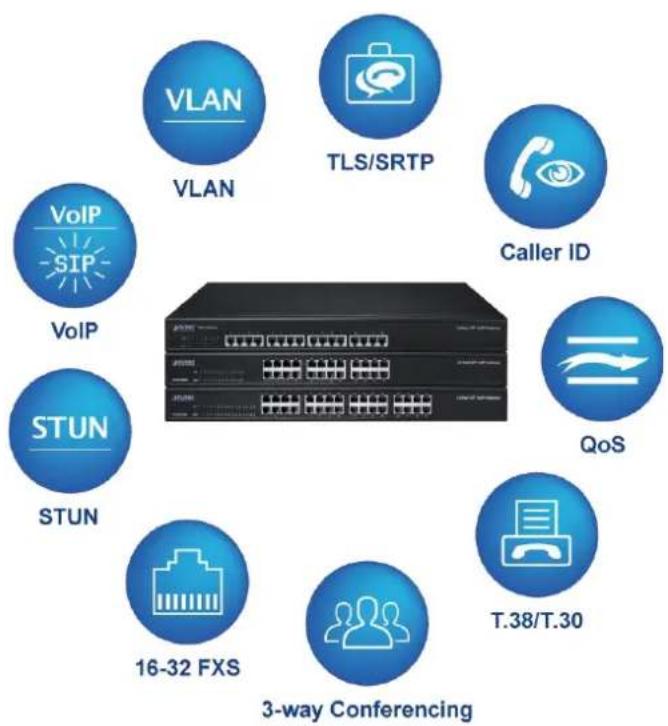
flowchart
graph TD
    A["VLAN"] --> B["VoIP"]
    C["TLS/SRTP"] --> D["VoIP"]
    E["Caller ID"] --> F["VoIP"]
    G["QoS"] --> H["STUN"]
    I["T.38/T.30"] --> J["16-32 FXS"]
    K["3-way Conferencing"] --> L["StUN"]
Distributed VoIP Network Infrastructure
The VGW-x20FS series is easy to use for all types of businesses as it offers quality voice communications and real-time fax data over IP networks. It does not need human resources to deploy a VoIP network. With the optimized SIP architecture, PLANET VGW-x20FS series is the ideal choice for P2P/SIP proxy (IP PBX) voice chat, and ITSP cost-saving solution.
1.2 Product Features
▶ SIP Applications
■ IETF SIP RFC 3261 based on UDP/TCP/TLS
■ Their 4, 8, 16, 24, and 32 FXS ports connect to analog phone sets or PABX systems.
■ Fax over T.38 and pass-through
■ ITU-T G.711 A-law, G.711 μ-law, G.723.1 and G.729 voice coding
■ In-band/out-of-band DTMF (RFC 4733, RFC 2833 and SIP info)
■ Echo cancellation exceeding ITU-T G.168, up to 128ms tail length
■ Supports SIP trunk and caller ID: DTMF/FSK CLI presentation
Internet Features
■ SNMP v1/v2/v3
■ VLAN 802.1P and 802.1Q
■ Layer3 QoS and DiffServ
■ STUN (RFC 3489) and outbound proxy
■ TR069 and auto provisioning
■ TLS/SRTP security
▶ Call Features
■ Call waiting and transfer (Blind transfer and attend transfer)
■ Call hold and quick pick
■ Call forwarding (Unconditional)
■ Call forwarding on no reply
■ Hotline, speed dial and direct IP call
■ Do not disturb (DND) and three-way conferencing
1.3 Function Specifications
| Product | VGW-420FS | VGW-820FS | VGW-1620FS | VGW-2420FS | VGW-3220FS |
| Hardware | |||||
| WAN | 1 x 10/100/1000BASE-T RJ45 port | - | - | - | |
| LAN | 1 x 10/100/1000BASE-T RJ45 port | 2 x 10/100/1000BASE-T RJ45 port | |||
| FXS Ports | 4 | 8 | 16 | 24 | 32 |
| Console | - | - | 1 x RS232, 115200bps | ||
| Weight | 300g | 300g | 2700g | 3200g | 3200g |
| Dimensions (W x D x H) | 194x110x28 mm | 194x110x28 mm | 440x230x44 mm | 440x250x44 mm | 440x250x44 mm |
| Power Requirements | 100-240VAC, 50-60 Hz | ||||
| Power Consumption | 5W | 18W | 30W | 40W | 40W |
| Protocols and Standard | |||||
| FXS | ■ Dial Mode: DTMF and Pulse■ Pulse: 10 and 20 PPS■ Caller ID: DTMF/FSK CLI Presentation■ Max. Cable Length: 3KM■ Reverse Polarity■ Programmable Call Progress Tone | ||||
| Voice & Fax | ■ G.711A/U law, G.723.1, G.729A/B,G.726 and iLBC■ Silence Suppression■ Comfort Noise Generation (CNG)■ Voice Activity Detection (VAD)■ Echo Cancellation (G.168), with up to 128ms■ Adaptive (Dynamic) Jitter Buffer■ Hook Flash■ Programmable Gain Control■ T.38/Pass-through■ Modem/POS■ DTMF mode: Signal/RFC 2833/INBAND■ VLAN 802.1P and 802.1Q■ Layer 3 QoS and DiffServ | ||||
| VoIP | ■ IETF Session Initiation Protocol (SIP) v2.0 (UDP/TCP)■ RFC 3261 and Session Description Protocol (SDP)■ RTP (RFC 2833), RFC 3262, RFC 3263, RFC 3264, RFC 3265, RFC 3515, RFC 2976 and RFC 3311■ RTP/RTCP, RFC 2198 and RFC 1889■ RFC 4028 Session Timer■ RFC 3266 IPv6 in SDP■ RFC 2806 TEL URI■ RFC 3581 NAT and rport■ Primary/Backup SIP Server■ Outbound Proxy■ DNS SRV/A Query/NATPR Query | ||||
| ■ SIP Trunk■ Early Media/Early Answer■ NAT:STUN, Static/Dynamic NAT | |||||
| Supplementary Service | ■ Call Waiting■ Blind Transfer■ Attend Transfer■ Call Forward on Busy■ Call Forward on No Reply■ Unconditional Call Forward■ Warm/Immediately Hotline■ Call Hold■ Do-not-disturb■ 3-way Conferencing■ Message Waiting Indicator | ||||
| Software Features | ■ Hunting Group■ Web ACL■ Telnet ACL■ Action URL■ PPPoE/IPv4/IPv6■ Digitmap■ Bandwidth Optimization■ Routing Rules based Prefixes■ Caller/Called Number Manipulation | ||||
| Management | ■ SNMP v1/v2/v3■ TR069■ Auto provisioning■ Web/Telnet■ Configuration backup/restoration■ Firmware upgrade via web■ CDR■ Syslog■ Ping and tracert test■ Network capture■ Outward test (GR909)■ NTP and daylight saving time■ IVR local maintenance | ||||
| Standards Conformance | |||||
| Emission | CE, FCC | ||||
1.4 Ports and Connectors
The FXS analog gateways are available in the following configurations:
| Model | Voice Channels | FXS Ports | Physical Port Labels |
| VGW-420FS | 4 | 4 | 0-3 |
| VGW-820FS | 8 | 8 | 0-7 |
| VGW-1620FS | 16 | 16 | 0-15 |
| VGW-2420FS | 24 | 24 | 0-23 |
| VGW-3220FS | 32 | 32 | 0-31 |
1.4.1 VGW-420FS
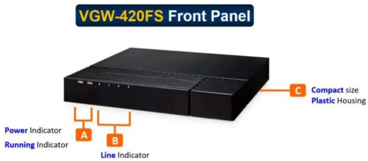
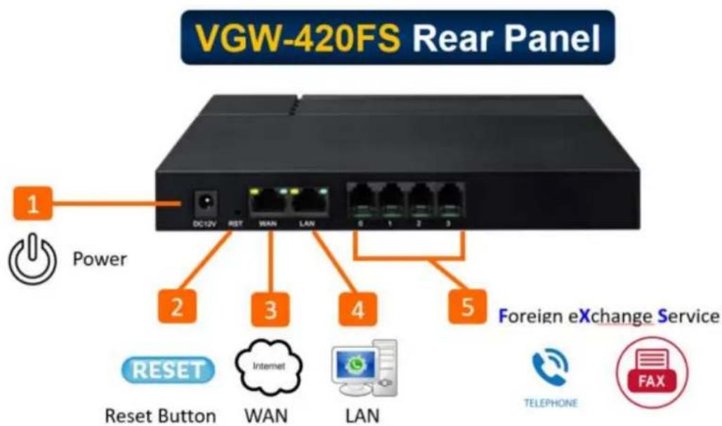
| Port Name | Connector | Description |
| Power Jack | Power Jack | To connect DC 12V power supply |
| WAN/LAN Port | RJ45 | To connect to the IP network over a DSL modem or router or a LAN switch |
| FXS Ports 0-3 | RJ11 | FXS ports to connect standard analog phone or fax machine or a PBX |
1.4.2 VGW-820FS
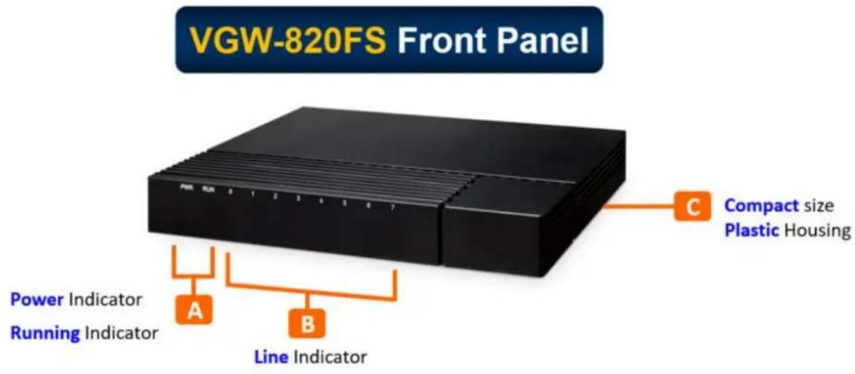
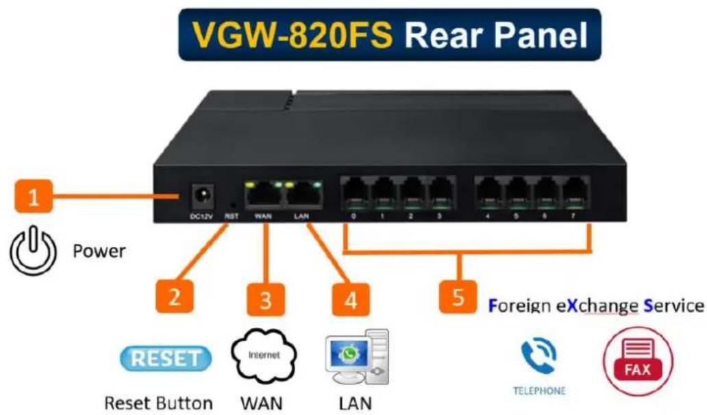
| Port Name | Connector | Description |
| Power Jack | Power Jack | To connect DC 12V power supply |
| WAN/LAN Port | RJ45 | To connect to the IP network over a DSL modem or router or a LAN switch |
| FXS Ports 0-7 | RJ11 | FXS ports to connect standard analog phone or fax machine or a PBX |
1.4.3 VGW-1620FS
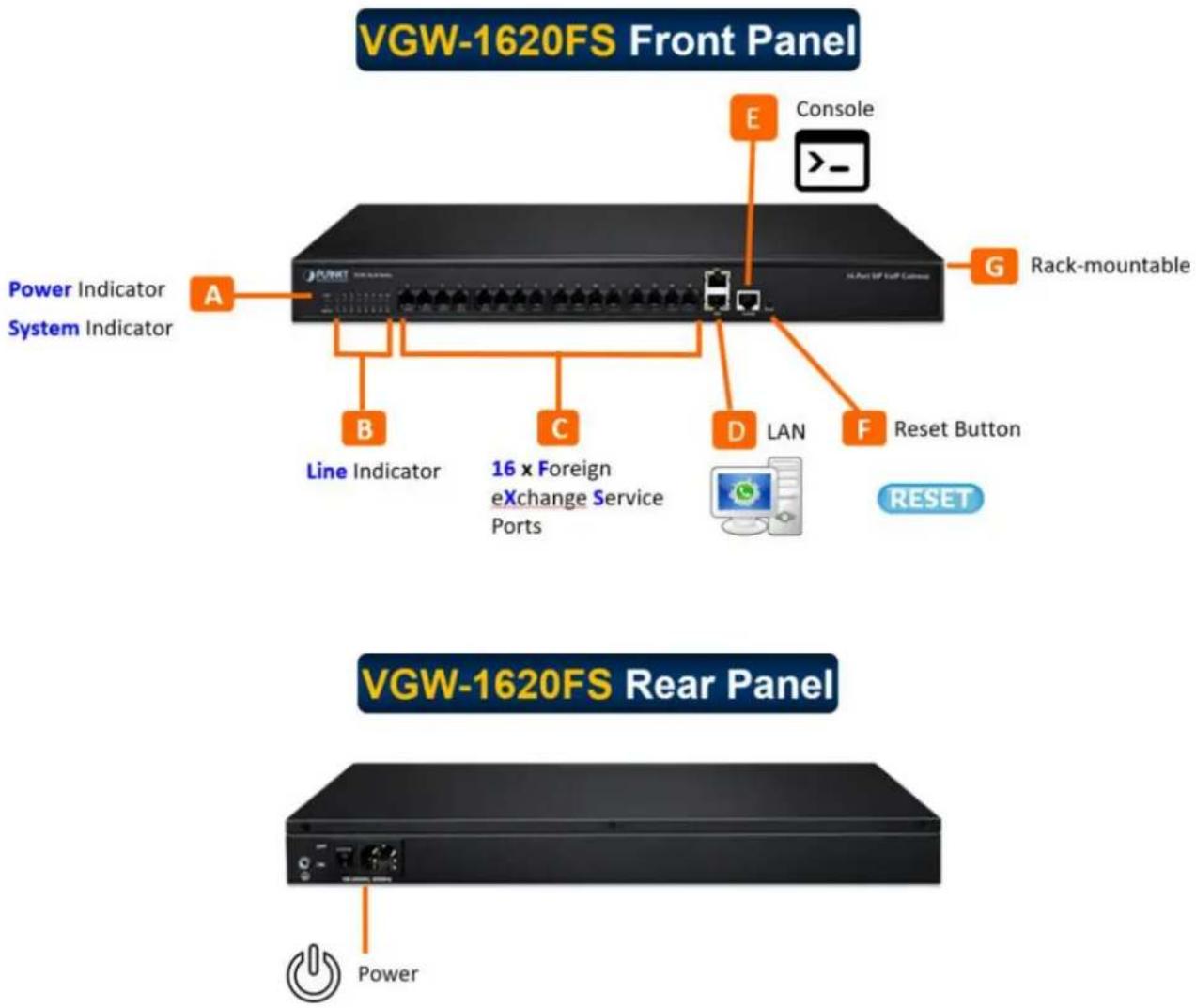
| Port Name | Connector | Description |
| Power Jack | Power Jack | To connect 100-240V AC 50-60HZ power supply |
| LAN Port | RJ45 | To connect to the IP network over a DSL modem or router or a LAN switch |
| FXS Ports 0-15 | RJ11 | FXS ports to connect standard analog phone or fax machine or a PBX |
| Console Port | RJ48 | Console port is used to carry out maintenance-related configurations |
1.4.4 VGW-2420FS
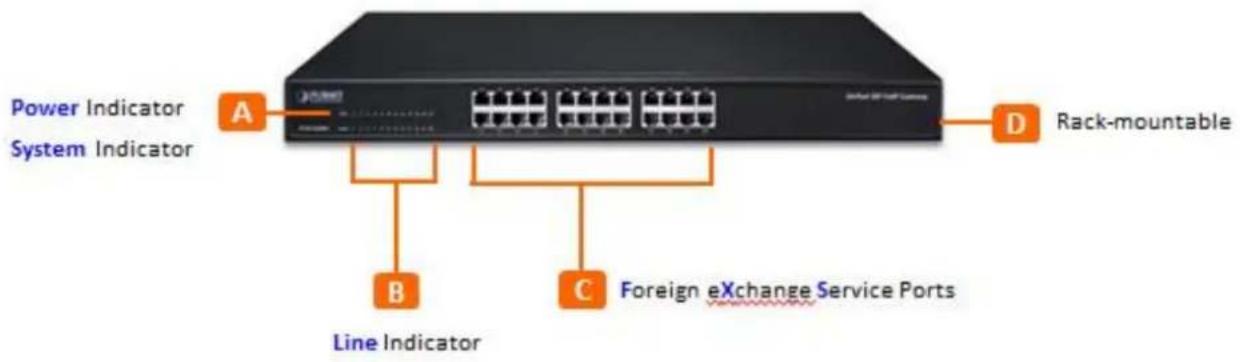
VGW-2420FS Front Panel
VGW-2420FS Rear Panel
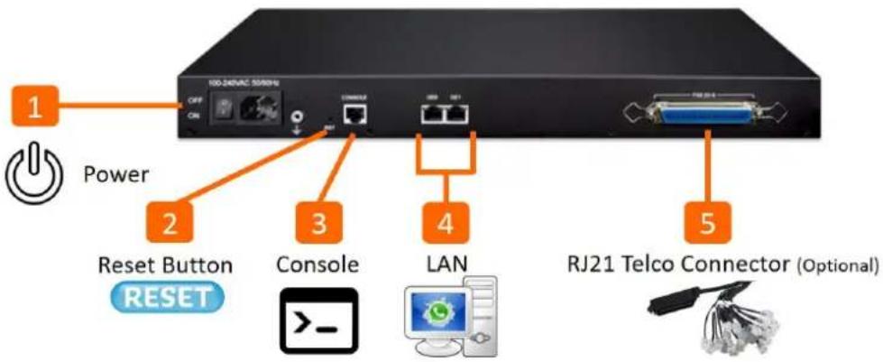
| Port Name | Connector | Description |
| Power Jack | Power Jack | To connect 100-240V AC 50-60HZ power supply |
| LAN Ports | RJ45 | To connect to the IP network over a DSL modem or router or a LAN switch |
| FXS Ports 0-24 | RJ11 | FXS ports to connect standard analog phone or fax machine or a PBX |
| Console Port | RJ48 | Console port is used to carry out maintenance-related configurations |
1.4.5 VGW-3220FS
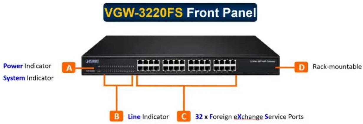
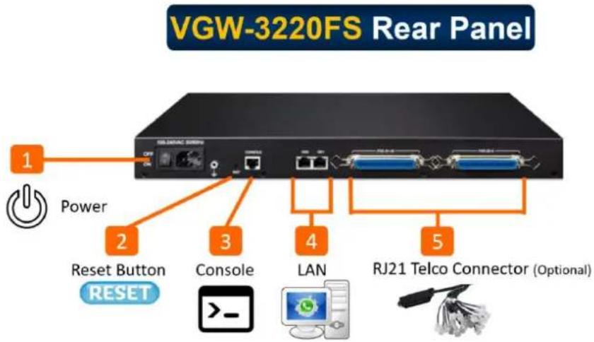
| Port Name | Connector | Description |
| Power Jack | Power Jack | To connect 100-240V AC 50-60HZ power supply |
| LAN Ports | RJ45 | To connect to the IP network over a DSL modem or router or a LAN switch |
| FXS Ports 0-31 | RJ11 | FXS ports to connect standard analog phone or fax machine or a PBX |
| Console Port | RJ48 | Console port is used to carry out maintenance-related configurations |
2 Basic Operations
2.1 Methods of Number Dialing
Dial mobile phone or extension number
▶ Dial the number directly and wait for 3 seconds (Default "No dial timeout");
▶ Dial the number directly and press #.
2.2 Direct IP Calls
The VGW-x20FS series allows users to directly call through IP address. Under this circumstance, the user only needs an analog phone which is connected to an FXS port of the gateway, and calls can be established without registration.
Calls can be established through IP address as long as one of the following conditions is met.
Both the VGW-x20FS series and other VoIP device have public IP addresses;
The VGW-x20FS series and other VoIP device use private IP addresses of the same LAN;
The VGW-x20FS series and other VoIP device can be connected through a router and use public or private IP addresses (with necessary port forwarding or DMZ).
Operation Process :
Step 1: Pick up the analog phone and then dial "*47";
Step 2: Enter the target IP address.

No dial tone will be played between step 1 and step 2.
Example:
Assume that the target IP address is 192.168.0.1, user need to dial *47 and then 192*168*0*1. After that, press the “#” key or wait for 3 seconds. Then signaling interaction is completed and ringing can be heard.

You cannot make direct IP calls between FXS0 and FXS1 of the same VGW-x20FS series since they are using the same IP addresses. Call through IP address is only routed to the default destination port 5060.
2.3 Call Holding
Place a call on hold by pressing the "flash" button on the analog phone (if the phone has the button). Press the "flash" button again to release the previously held caller and resume conversation. If no "flash" button is available, use "hook flash" instead.
2.4 Call Waiting
If a calling party places a call to a called party which is otherwise engaged, and the called party has the call waiting feature enabled, the calling party will hear a IVR voice 'Please hold on, the subscriber you dialed is busy' and the called party will hear three beeps.
By pressing the flash button or the flash hook, the called party is able to switch between the new incoming call and the current call.
2.5 Call Transfer
2.5.1 Blind Transfer
Blind transfer is used to transfer call to a third party without informing the caller. Assume that A and B are in a conversation. A wants to blind Transfer B to C:
▶ A presses FLASH on the analog phone to hear the dial tone;
Then A dials *87 and C's number and # (or wait for 4 seconds);
▶ A will hear the confirm tone. Then, A hangs up, and B and C enter into a conversation.
Note :
"Call features enable" must be set to "Yes" on Web configuration page. Caller A can place a call on hold and wait for one of the three situations:
▶ A quick confirmation tone (similar to call waiting tone) which follows the dial tone. This indicates the transfer is successful. At this point, Caller A can either hand up or make another call.
▶ A quick busy tone which follows a restored call (on supported platforms only). This means the transferee has received a 4xx response for the INVITE and we will try to recover the call. The busy tone indicates the transfer has failed.
▶ Continuous busy tone. This means the call has timed out.
2.5.2 Attended Transfer
Attended transfer allows the transferring party either connects the call to a ringing phone (ringback heard) or speaks with the third party before transferring the call to the third party.
Assume that A and B are in conversation. Caller A wants to attended transfer B to C:
▶ A presses FLASH on the analog phone and wait for dial tone;
Then dial C's number followed by # (or wait for 3 seconds);
If C answers the call, A and C are in conversation. Then A can hang up to complete the transfer;
If C does not answer the call, A can press "flash" to resume call with B.
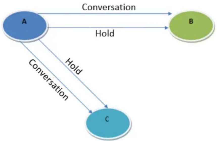
2.6 Three-way Calling
Three-way calling
▶ A calls B,B picks up the phone, then A and B enters into conversation;
▶ A presses the hook flash, and the call between A and B is placed on hold. Then C calls A and A answers the call.
▶ A presses hook flash again, then the calls between A and B and between A and C are placed on hold. At this time, if A presses 1, conversation between A and B is resumed; if A presses 2, conversation between A and C is resumed; if A presses 3, A, B and C enter into conversation.
flowchart
graph TD
    A["A"] -->|Conversation| B["B"]
    A -->|Hold| B
    A -->|Conversation| C["C"]
    B -->|Hold| C
2.7 Description of Feature Codes
The VGW-X20FS SERIES gateway supports all traditional and senior phone functions. It provides feature codes for easy maintenance and easy entry to phone functions.
| Feature Codes | Corresponding Function |
| *158# | Dial *158# to inquiry the IP address of LAN port |
| *159# | Dial *159# to inquiry the IP address of WAN port |
| *114# | Dial *114# to inquire port account |
| *150* | Dial *150* to set the way of obtaining IP address |
| *157* | Dial *157*0 to set route mode; dial *157*1 to set bride mode |
| *152* | Dial *152* to set IPv4 address |
| *153* | Dial *153* to set subnet mask |
| *156* | Dial *156* to set default gateway's IP address |
| *193# | Dial *193# to renew the IP address |
| *160*1# | Dial *160*1# to open WAN port to visit web |
| *166*000000# | Dial *166*000000# to reset to factory defaults |
| *111# | Dial *111# to restart the gateway |
| *# | Dial *# to place a call on hold |
| *47* | Dial *47* to establish a call through IP address |
| *51# | Dial *51# to enable 'call waiting' feature |
| *50# | Dial *50# to disable 'call waiting' feature |
| *87* | Dial *87* to blind transfer a call |
| *72* | Dial *72* to enable 'unconditional call forwarding' feature |
| *73# | Dial *73# to disable 'unconditional call forward' feature |
| *90* | Dial *90* to enable 'busy call forwarding' feature |
| *91# | Dial *91# to disable 'busy call forwarding' feature |
| *92* | Dial *92* to enable 'no answer call forwarding' feature |
| *93# | Dial *93# to disable 'no answer call forwarding' feature |
| *78# | Dial *78# to enable DND |
| *79# | Dial *79# to disable DND |
| *200# | Dial *200# to access voice mail |
| Flash/Hook | Used to switch between incoming calls. If the phone is not in session, flash/hook will switch a new channel for a new call. |
2.8 Sending and Receiving Fax
The VGW-X20FS SERIES gateway supports four fax modes:
▶ T.38 (FolP)
▶ Pass-through
▶ Modem
Adaptive
2.8.1 T. 38 and Pass-through
T.38 is the preferred fax mode because it is more reliable and works well in most network conditions. If the service provider supports T.38, please use this method by selecting T.38 as fax mode (default). If the service provider does not support T.38, pass-through mode may be used. If you have problems with sending or receiving Fax, toggle the Fax Tone Detection Mode setting.
2.9 Local IVR Operation
2.9.1 Inquire IP address
Connect analog phone to FXS ports of the VGW-X20FS SERIES gateway, then pick up the phone. After dialing tone, dial *158# to inquire the IP address of LAN port and dial *159# to inquire the IP address of WAN port.
2.9.2 Factory Reset
Pick up the phone, and then dial *166*000000#. After hearing a voice prompt of 'setting successfully', hang up the phone and the gateway is reset to factory defaults.
2.9.3 Configure LAN Port's IP Address
Before configuration, please ensure:
▶ The gateway is power on;
▶ Device has been connected to network;
▶ Telephone is connected to FXS port of the VGW-X20FS SERIES gateway.
Configure dynamic IP address by DHCP:
Pick up the phone, dial *150*2# and then hang up the phone.
If the voice prompt indicates 'setting successfully', please restart the gateway after 10 seconds.
Configure Static IP address:
Take the configuration of IP address '172.16.0.100' for an example.
Pick up the phone, dial *150*1# and then hang up the phone.
Then configure IP address and mask as follows:
- Configure IP address
Pick up the phone, dial *152*172*16*0*100# and then hang up the phone. - Configure subnet mask
Pick up the phone, dial *153*255*255*0*0# and then hang up the phone. - Configure gateway IP address
Pick up the phone, dial *156*172*16*0*1# and then hang up the phone. - Query the IP address of the VGW-X20FS SERIES gateway:
Pick up the phone, dial *158#.
If the gateway uses PPPoE method to get IP address, the IP address needs to be configured through web browser.

The telephone will play voice prompt "setting successfully" if the step is correct.
3 Configurations on Web Interface
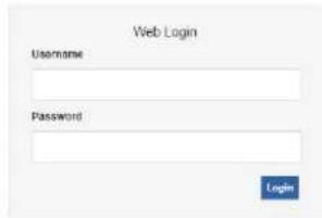
3.1 Logging in Web Interface
The VGW series is easy to install by following the steps below.
Step 1 : Connect a computer to a LAN port on the VGW series. Your PC must be set to 192.168.0.X, the same domain as that of the VGW series.
Step 2 : Start a web browser. To use the user interface, you need a PC with Internet Explorer (version 8 or higher), Firefox, or Safari (for Mac).
Step 3 : Enter the default IP address of the VGW series: http://192.168.0.1 into the URL address box.
Step 4 : Enter the default user name admin and the default password admin, and then click Login to enter Web-based user interface.

PLANET
SIP VoIP Gateway
3.2 Navigation Tree
The web management system of the VGW-X20FS SERIES VoIP gateway consists of the navigation tree and detailed configuration interfaces.
Choose a node of the navigation tree to enter into a detailed configuration interface.
- Status & Statistics
- System Information
- Registration
- TCP/UDP Traffic
- RTP Session
CDR - Quick Setup Wizard
- Network
- SIP Server
• Port - Advanced
- Call & Routing
- Manipulation
- Management
- Security
- Tools
Note: When the gateway works in the bridge mode, configuration items including "Routing Configuration", "DHCP Service", "DMZ Host", "Forward Rules" and "Static Routing" and "ARP" will not be displayed.
3.3 State and Statistics
3.3.1 System Information
On the System Information interface, you can view the information of device ID, MAC address, network mode, IP addresses, version information, sever register status and so on.
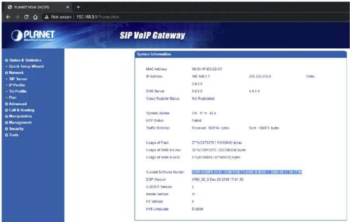
Figure 3.5-1 System Information
Explanation of items on System Information interface
| Device ID | A unique ID of each device. This ID is used for warranty and cloud server authentication |
| MAC address | Hardware address of the WAN port |
| Network Mode | Network modes include bridge and router. In the Bridge mode, the network port will work as a small LAN switch. In the Router Mode, NAT feature will be enabled. |
| WAN IP Address (VGW-420FS/VGW-820FS only) | The IP address of the WAN port of the gateway is shown.DHCP: Obtain IP address automatically. VGW-X20FS SERIES is regarded as a DHCP client, which sends a broadcast request and looks for a DHCP server from the LAN to answer. Then the first discovered DHCP server automatically assigns an IP address to the VGW-X20FS SERIES from a defined range of numbers.Static IP Address: Static IP address is a semi-permanent IP address and remains associated with a single computer over an extended period of time. This differs from a dynamic IP address, which is assigned ad hoc at the start of each session, normally changing from one session to the next.If you choose static IP address, you need to fill in the following information:IP Address: The IP address of the WAN port of the VGW-X20FS SERIES;Subnet Mask: The netmask of the router connected to the VGW-X20FS SERIES;Default Gateway: The IP address of the router connected to the VGW-X20FS SERIES;PPPoE: PPPoE is an acronym for point-to-point protocol over Ethernet, which relies on two widely accepted standards: PPP and Ethernet. PPPoE is a specification for connecting the users on an Ethernet to the Internet through a common broadband medium, such as a single DSL line, wireless device or cable modem. PPPOE IP address refers to IP address assigned through the PPPoE mode.If you choose PPPoE, you need to fill in the following information:Username: The account name of PPPoEPassword: The password of PPPoEServer Name: The name of the server where PPPoE is placed |
| LAN IP address | IP address of the LAN port of the gateway is shown. If network mode is bridge, LAN port won't be displayed. |
| DNS Server | IP address of DNS server and default gateway information is displayed. |
| Cloud Register Status | Whether the VGW-X20FS SERIES gateway is registered to cloud or not. |
| System Uptime | The running time of the VGW-X20FS SERIES since it is powered on. |
| NTP Status | Successful: The VGW-X20FS SERIES gateway is in sync with NTP server successfully;Failed: the VGW-X20FS SERIES gateway fails to be in sync with NTP server. Then you should check network connection and the NTP server. |
| Network Traffic Statics | Total bytes of message received and sent by network port. |
| Usage of Flash | Detailed usage of Flash memory |
| Usage of RAM in Linux | Detailed RAM usage of Linux core |
| Usage of RAM in AOS | Detailed RAM usage of AOS |
| Current Software Version | The software version that runs on the gateway. Model name, version number and the software development date are displayed. |
| Backup Software Version | Backup software is for the purpose of backing up. When the current software fails, the backup software version will work. |
| U-boot | U-boot version |
| Kennel version | Linux Kennel version |
| FS Version | File system version |
| Hint Language | The current language of the VGW-X20FS SERIES gateway |
3.3.2 Registration Information
| Port Registration Information | |||||
| Port No. | Type | Primary User ID | Primary User Status | Secondary User ID | Secondary User Status |
| 0 | FXS | 6001 | Registered | --- | --- |
| 1 | FXS | 6002 | Registered | --- | --- |
| 2 | FXS | 6003 | Registered | --- | --- |
| 3 | FXS | 6004 | Registered | --- | --- |
| Port Group Registration Information | |||||
| Port Group | Port | Primary User ID | Primary User Status | Secondary User ID | Secondary User Status |
| -- | -- | -- | -- | -- | -- |
Figure 3.5-2 Port and Port Group Registration Information
Primary/Secondary User status:
▶ Registered: The port is registered to SIP server successfully;
▶ Unregistered: The port fails to be registered to SIP server.
3.3.3 TCP/UDP Statistics
| TCP/UDP Traffic | |||
| TCP Sent Packets | TCP Recv Packets | UDP Sent Packets | UDP Recv Packets |
| 1092 | 820 | 567 | 311 |
| Refresh | |||
Figure 3.5-3 TCP/UDP Statistics Information
The above interface shows the statistical number of sending or receiving packets over TCP, and the number of sending or receiving packets over UDP since the VGW-X20FS SERIES is booted up.
3.3.4 RTP Session Statistics
| RTP Session | ||||||||||
| Port | Payload Type | Packet Period | Local Port | Peer IP | Peer Port | Sent Packets | Recv Packets | Lost Packets | Jitter | Duration(s) |
| - | - | - | - | - | - | - | - | - | - | |
Figure 3.5-4 RTP Session Statistics
The above interface shows real-time RTP session information, including port, payload type, packet period, local port, peer IP, peer port, sent packets, receive packets, lost packets, jitter and duration.
3.3.5 CDR Statistics
CDR (Call Detail Record) is a data record produced by a telephone exchange or a telecommunication device, which contains the details of a telephone call that passes through the device.
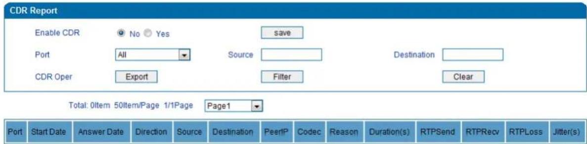
On the Status & Statistic → CDR interface, details of all calls through the ports of the VGW-X20FS SERIES are displayed. The CDR function can be enabled on this interface.
3.4 Quick Setup Wizard
Quick setup wizard guides user to configuring the device step by step. User only needs to configure network, SIP server and SIP port in the Quick Setup Wizard interface. Basically, after these three steps, user is able to make voice call via the VGW-X20FS SERIES device.
3.5 Network Configuration
3.5.1 Local Network
The VGW-X20FS SERIES gateway has two kinds of network mode: route and bridge. When the gateway works in the route mode, it will work as a small router and NAT function is enabled. Under this situation, WAN port is normally connected to router/switch or ADSL MODEM, while LAN port is connected local computer or other network devices (such as Ethernet switches, hubs, etc.).
When the gateway works in the bridge mode, WAN port and LAN port are the same. The gateway serves as a two-port Ethernet switch. In this network mode, user only needs to configure the IP address of WAN port and DNS.
DHCP:
Obtain IP address automatically.
Static IP Address:
Static IP address is a permanent IP address which is assigned by Internet Service Provider (ISP) and remains associated with a single computer over an extended period of time. This differs from a dynamic IP address, which is assigned ad hoc at the start of each session, normally changing from one session to the next.
PPPoE:
PPPoE is an acronym for point-to-point protocol over Ethernet, which relies on two widely accepted standards: PPP and Ethernet. PPPoE is a specification for connecting the users on an Ethernet to the Internet through a common broadband medium, such as a single DSL line, wireless device or cable modem. All the users over the Ethernet share a common connection, so the Ethernet principles supporting multiple users in a LAN combine with the principles of PPP, which apply to serial connections.
PPPOE IP address refers to IP address assigned through the PPPoE mode.
If you choose PPPoE, you need to fill in the account, password and service name, which are provided by telecom operator.
Local Network
Network Mode

Router

Bridge
WAN Port
○ Obtain an IP address automatically
Use the following IP address
IP Address
Subnet Mask
Default Gateway
172.16.0.1
255.255.0.0
172.16.0.254
○ PPPoE
Account
Password
Service Name
WAN MTU
1400
LAN Port
IP Address
Subnet Mask
192.168.0.1
255.255.255.0
DNS Server
Obtain DNS server address automatically
Use the following DNS server address
Primary DNS Server
Secondary DNS Server
8.8.8.8
4.4.4.4
Figure 3.7-1 Route Mode
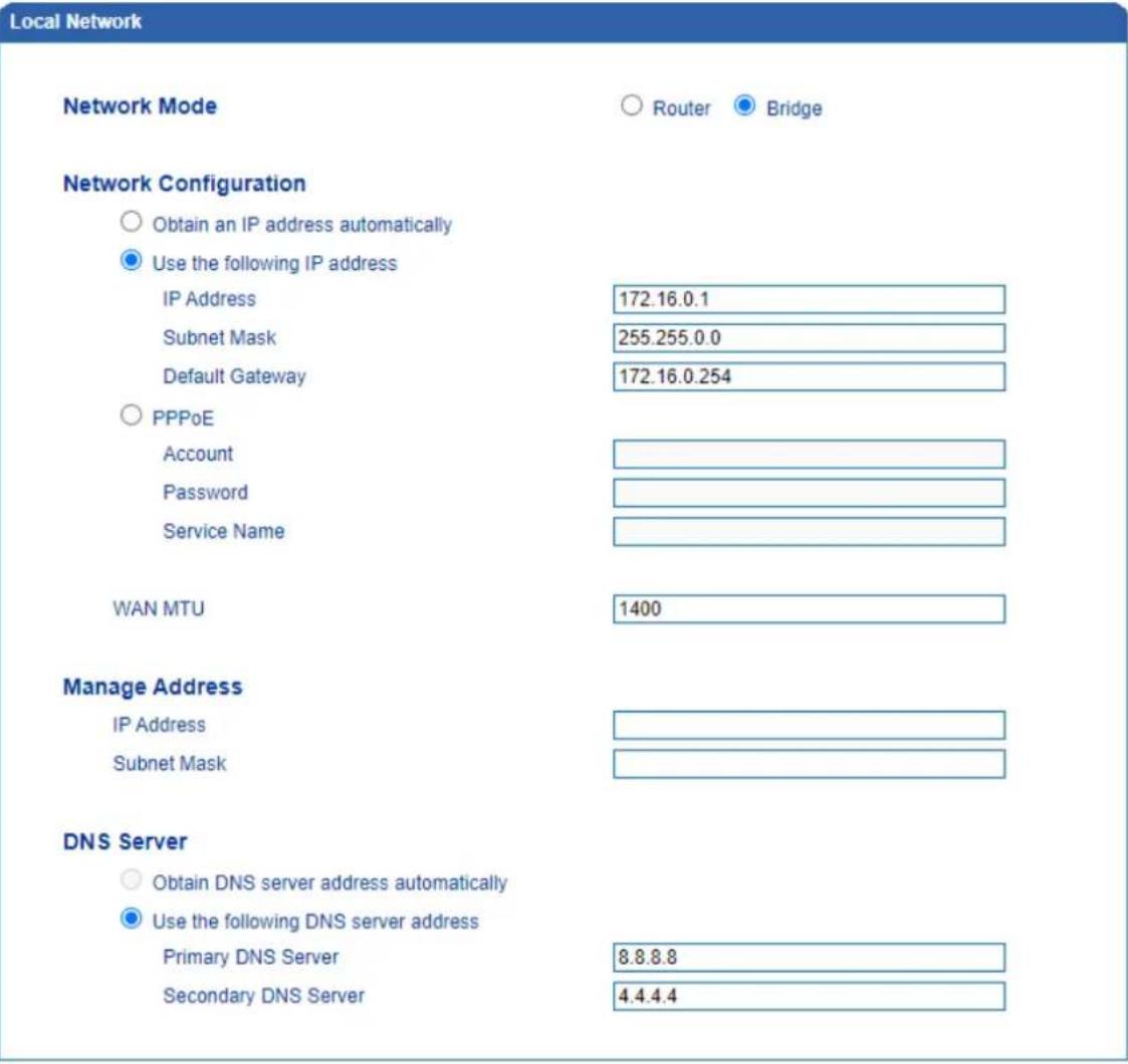
Figure 3.7-2 Bridge Mode
| Note | If DHCP is selected to obtain IP address, please ensure DHCP server in the network works normally. When the gateway works in the route mode, the IP address of LAN port and that of WAN port cannot be in the same network segment, otherwise the gateway can't work normally. When the gateway works in the route mode, log in the gateway's web configuration interface via the LAN port. After the configurations are finished, please restart the gateway for the configurations to take effect. |
3.5.2 VLAN (Virtual Local Area Network)
In order to control the impacts brought by broadcast storms, user can divide VLANs into three groups, namely VLAN1, VLAN2 and VLAN3. There are three kinds of VLANs, including data VLAN, voice VLAN and management VLAN. Different kinds of VLANs have different messages.
▶ 802.1Q
The IEEE 802.1Q standard defines the architecture for Virtual Bridged LANs; the services provided in Virtual Bridged LANs and the protocols and algorithms are involved in the provisions of those services.
No Quality of Service mechanisms are defined in this standard, but an important requirement for providing QoS is included in this standard, e.g. the ability to regenerate user priority of received frames using priority information contained in the frame and the User Priority Regeneration Table for the reception Port.
▶ 802.1P
IEEE 802.1P standard describes important methods for providing QoS at MAC level. IEEE 802.1p is in fact quite good. Lower priority level packets are not sent, if there are packets in queued in higher level queues. IEEE 802.1p describes no admission control protocols. It would be possible to give Network Control priority to all packets and the network would be easily congested.
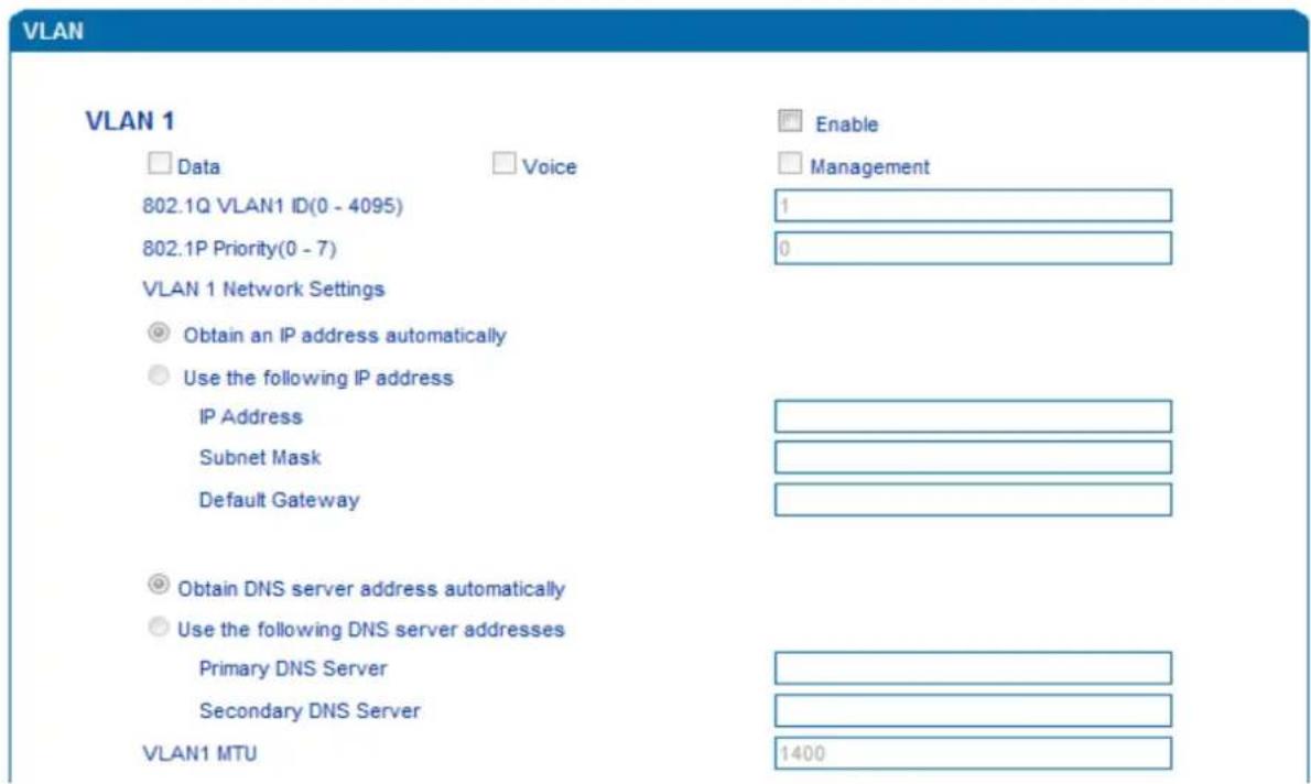
Figure 3.7-3 VLAN parameter configuration
Explanations of the parameters in VLAN interface:
| VLAN1/VLAN2/VLAN3 | The gateway supports three VLANs at most. Please enable VLAN according to actual needs. |
| Data/Voice/Management, | If the checkboxes on the right of data, voice and management of VLAN1 are selected, it means data messages, voice messages and management messages are subject to the network setting, 802.1Q VLAN1 ID and 802.1P Priority of VLAN1. |
| 802.1Q VLAN ID(0-4095) | Set an ID to identify a VLAN based on 802.1Q protocol. |
| 802.1p Priority (0-7) | Set the priority of a VLAN based on 802.1P protocol. |
| Network Setting | Set a DHCP IP address or static IP address for a VLAN, and set the IP address of the DNS server used by the VLAN. |

User needs to restart the gateway for the configurations to take effect.
3.5.3 DHCP Server (Route Mode for VGW-420FS/820FS)
When the gateway works in the route mode, it works as a small router and user can its DHCP service so that the VGW-X20FS SERIES serves as a DHCP server in the network.
"Start address" and "end address" of the address pool determine the range of IP addresses which are automatically assigned to other devices.
▶ "IP Expire Time" means the service time of an assigned IP address. When the service time expires, the IP address will no longer be valid.
The subnet mask, gateway, DNS and other information will be transferred to the network equipment through the DHCP protocol.
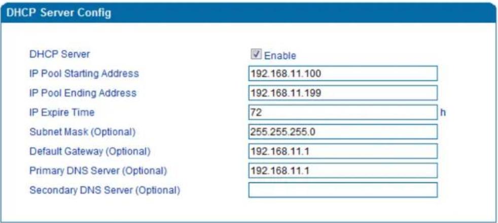
Figure 3.7-4 DHCP Server Configuration Interface

Note
When configuring the start IP address, end IP address, subnet mask and gateway IP address, please set them in the same network segment with the IP address of LAN port. Otherwise, other devices under the network will not work normally after they get the IP address assigned by the DHCP server. After the configurations are finished, please restart the VGW-X20FS SERIES for the configurations to take effect.
3.5.4 DMZ Host (Route Mode for VGW-420FS/820FS)
If the DMZ service is enabled, the devices in the wide-area network are allowed to have direct access to the devices in the DMZ (demilitarized zone). In this way, devices in the wide-area network can visit the devices which are in the local area network and meanwhile the devices in the local area network are protected.
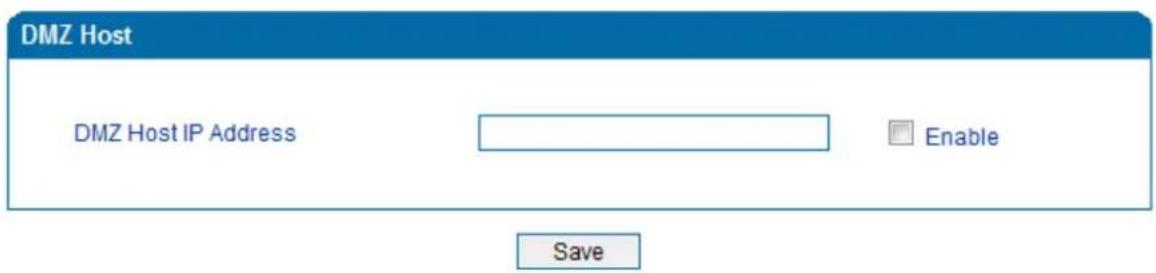
Figure 3.7-5 DMZ Configuration Interface

After the configurations are finished, please restart the VGW-X20FS SERIES for the configurations to take effect.
3.5.5 Forward Rule (Route Mode for VGW-420FS/820FS)
Sometimes, a device under the LAN network needs to provide a port for communication with the WAN network (such as providing the port 21 for FTP service). In those cases, user can configure forwarding rules for that network device.
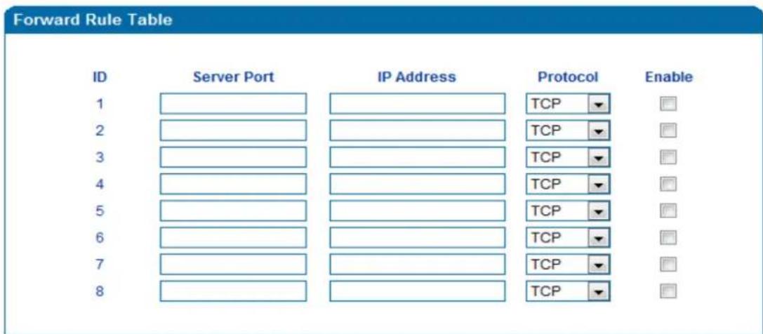
Figure 3.7-6 Configuration Interface for Forwarding Rules
Service port is the port that provides service for the WAN network, while IP address is the IP address of the network device under the LAN network. The protocol is TCP or UDP.
The difference between forwarding rule and DMZ host is that DMZ Host offers all ports (0-1024) and protocols for outside telecommunication while forwarding rule only offers a single or several ports and protocols of TCP or UDP.

When both DMZ Host and forwarding rule are configured, the configuration of forwarding rule is prior to that of DMZ Host.
3.5.6 Static Route (Route Mode for VGW-420FS/820FS)
Static route determines the routing rule during the handling of messages by the gateway. Most of time, user does not need to configure static route. Only when there are multiple network segments in the LAN network, these segments need to complete some specific applications, and static route needs to be configured.
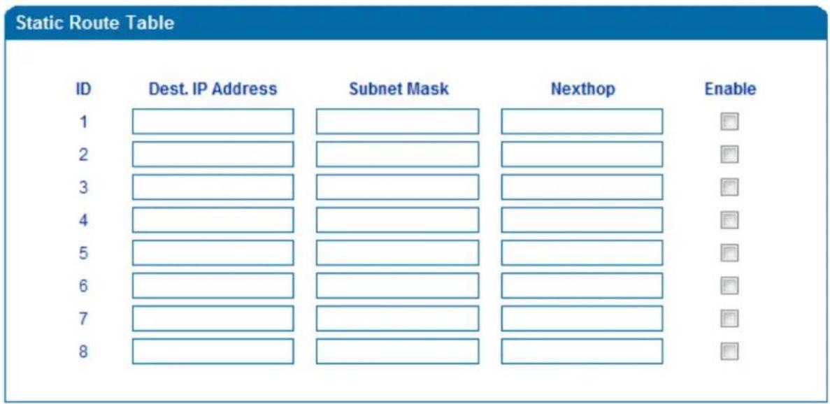
Figure 3.7-7 Configuration interface for Static Route
3.5.7 ARP
ARP or address resolution protocol helps user get the MAC address of a device through its IP address. Under TCP/IP network environment, each host is assigned with a 32-bit IP address, but MAC address needs to be known for message transmission in the physical network. ARP is a tool that converts IP address into MAC address.
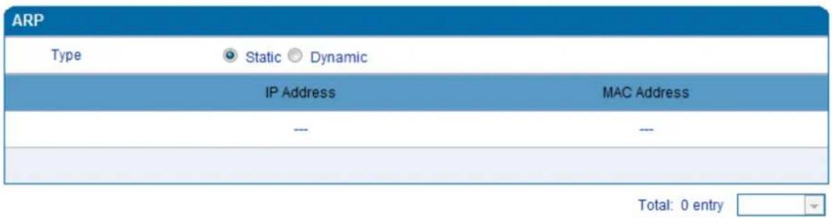
Figure 3.7-9 ARP Parameters
3.6 SIP Server
Introduction of SIP Server:
1) SIP server is the main component of VoIP network and is responsible for establishing all the SIP calls. SIP server is also called SIP proxy server or register server. Both IPPBX and softswitch can act as the role of SIP server.
2) Usually, SIP server does not participate in media processing. Under SIP network, media always use end-to-end negotiating. Simple SIP server is only responsible for the establishment, maintenance and cleaning of sessions, while relatively-complex SIP server (SIP PBX) not only provides basic calling and conversational support, but also offers rich services such as Presence, Find-me and Music On Hold.
3) SIP server based on Linux platform like OpenSER, sipXecx, VoS, Mera or other.
4) SIP server based on Windows platform like mini SipServer, Brekeke, VoIPswitch or other.
5) Carrier-grade softswitch platform like Cisco, Huawei, ZTE or other.
SIP Server
Primary SIP Server
Primary SIP Server Address
Primary SIP Server Port (Default: 5080)
Registration Expires (Default: 1800)
Heartbeat
ims.telekomsrbija.com
5060
3800

Enable
Secondary SIP Server
Secondary SIP Server Address
Secondary SIP Server Port (Default: 5060)
Registration Expires (Default: 1800)
Heartbeat
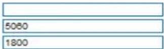

Enable
Primary Outbound Proxy
Primary Outbound Proxy Address
Primary Outbound Proxy Port
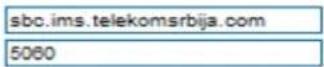
Secondary Outbound Proxy
Secondary Outbound Proxy Address
Secondary Outbound Proxy Port
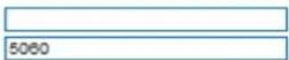
Registration
Retry Interval when Registration failed
Registration times per second (0 means unlimited)

SIP Transport Type
Local SIP Port
Use Random Port
SIP UDP/TCP Local Port
SIP TLS Local Port
Enable
5060
5061
Figure 3.8-1 Configuration Interface for SIP Server
Explanation of SIP parameters:
| Primary SIP Server Address | The IP address or domain name of the primary SIP server is provided by VoIP service provider. |
| Primary SIP Server port | The Service port of the primary SIP server is 5060 by default. |
| Registration Expires | It is used to avoid excessively frequent registrations.When the time that is set expires, terminals will send register request to the primary SIP server. The time is 1800s by default. |
| Heartbeat | Heartbeat is used to check the connection between terminal and SIP server. |
| Secondary SIP Server address | The IP address or domain name of the backup SIP server is provided by VoIP service provider. |
| Secondary SIP Server port | Service port of the backup SIP server is 5060 by default. |
| Registration Expires | It is used to avoid excessively frequent registrations.When the time that is set expires, terminals will send register request to the backup SIP server. The time is 1800s by default. |
| Secondary SIP heartbeat | Heartbeat is used to check the connection between terminal and SIP server. |
| Outbound Proxy Address | Outbound proxy IP address or domain name is provided by VoI service provider. |
| Outbound Proxy Port | Default outbound proxy port is 5060. |
| Retry Interval when Registration failed | The retry interval time after a registration fails is 30s by default. |
| Registration Times per Second | The maximum number of registrations in a second. 0 means no limitation for registrations. |
| SIP Transport Type | SIP-based transmission includes UDP, TCP ir Auto. Default: UDP. |
| Use Random Port | The SIP port for providing services for terminal is chosen at random. |
| SIP Local Port | Default SIP local service port is 5060. |
3.7 Port
Port Modify
Port
0
Disable Port
回
Registration
√
Enable
Primary Display Name
Primary SIP User ID
8001
Primary Authenticate ID
8001
Primary Authenticate Password

Secondary Display Name
Secondary SIP User ID
Secondary Authenticate ID
Secondary Authenticate Password

Offhook Auto-Dial
Auto-Dial Delay Time
DND(Do Not Disturb)
F
Enable
Caller-ID
√
Enable
Number for CFU(Call Forwarding Unconditional)
Number for CFB(Call Forwarding Busy)
Number for CFNRy(Call Forwarding No Reply)
natural_image
Three horizontal rectangular bars with no text or symbolsCall Waiting
回
Enable
Play Call Waiting Tone
□
Enable
Figure 3.9-1 Port Configuration Interface
Explanation of port parameters:
| Port | Port number |
| Disable port | Whether to disable port temporarily |
| Registration | Whether to enable registration for the port |
| Primary/Secondary SIP Display Name | Primary /Secondary SIP account description. It is used to identify the SIP account |
| Primary/Secondary SIP User ID | User account information provided by VoIP service provider (ITSP). Usually in the form of digit similar to phone number or actually a phone number. |
| Primary/Secondary SIP Authenticate ID | SIP service subscriber's authenticated ID used for authentication. It can be identical to or different from SIP User ID. |
| Primary/Secondary Authenticate password | SIP password which registers to soft switch/SIP server |
| Offhook Auto-dial | An extension or phone number is pre-assigned here so that the number is automatically dialed as soon as user picks up the phone |
| Auto-dial Delay Time | How long the auto-dial number is prolonged. If it is set as 3s, the auto-dial number is dialed after 3 seconds expire. |
| DND | The phone won't receive any calls in case it enabled. |
| Caller ID | Enable or disable caller ID for corresponding port. If it is disabled, the caller ID for the calls through the port won't be displayed. |
| Number for CFU | Call forward unconditional. All incoming calls will be forwarded to pre-assigned number automatically |
| Number for CFB | Call forward on busy. If the line is busy, the call will be forwarded to pre-assigned number automatically |
| Number for CFNRy | Call forward no reply. If the call is not answered, the call will be forwarded to pre-assigned number automatically |
| Call Waiting | If call waiting is enabled, a special tone is sent if another caller tries to reach you |
| Play Call Waiting Tone | If call waiting tone is enabled, caller will hear special tone. |
3.8 Advanced
3.8.1 FXS/FXO Parameters
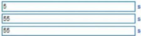
FXS parameters include: timeout Call Progress Tone, Timeout for Dialing, Send Polarity Reversal, etc.
FXS / FXO
Timeout for Dialing
Timeout for Answer(Outgoing Call)
Timeout for Answer(Incoming Call)
No RTP Detected
Period without RTP Packet
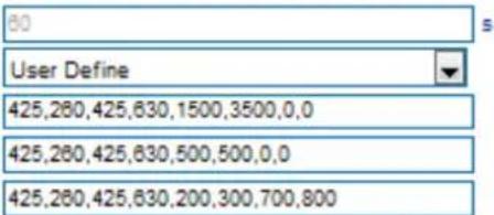
Call Progress Tone
Ring Back Tone
Busy Tone
Dial Tone
Auto Gain Control
Enable
Enable
Line Parameter
Port
Work Mode
Voice Output Mode
Config Mode(Gain)
Tx Gain
Rx Gain

Telephone
Headset
Basic
Advanced

FXS Parameter
Send Polarity Reversal
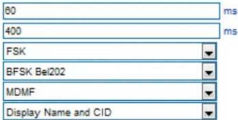
Detect Hook Flash
Min Time
Max Time
CID Type
Modulation Type
Message Type
Message Format
Send CID before Ringing
Delay of Sending CID after Ringing
CFNRy Timeout
SLIC Setting
REN
Long Line Support
Enable
Enable
Enable
Enable
Figure 3.10-1 Configuration Interface for FXS Parameters
Explanation of FXS parameters:
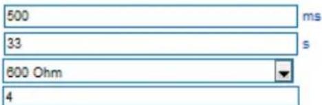
| Timeout for dialing | With the help of dialing timeout, you can limit the time between two digits while users are typing the digits of a number through an extension. If the timeout expires, the gateway will consider the dialing has finished and will try to send message to SIP server. Default value is 4 seconds. |
| Timeout for answer (Outgoing call) | This parameter determines how long the caller party will wait for answer when making outgoing calls through a phone. |
| Timeout for answer (Incoming call) | This parameter determines how long the phone rings when there are incoming calls |
| No RTP Detected | If this parameter is enabled, the situation will be detected when there is no RTP packets received during the set time period. |
| Period without RTP Packet | The time period when there is no RTP packets received. |
| Call Process Tone | The signal tone standard after a phone is picked up. Choose national standards from the drop-down box. Default value is the United States. |
| Auto Gain Control | Whether to enable automatic gain control |
| Send Polarity Reversal | If polarity reversal is enabled, call tolls will be calculated based on the changes in voltage. If polarity reverse is disabled, you need to set the time for offhook detection and call tolls will be calculated starting from the set time. |
| Detect Hook flash | If 'Detect Hook Flash' is enabled, you need to set a minimum time and a maximum time. If a phone's hook flash is pressed for a time period greater than the set minimum time but less than the maximum time, the action is considered as a 'hook flash' operation. If a phone's hook flash is pressed for more the set maximum time, the action is considered as 'hang up the phone'. |
| CID Type | There are two CID types, namely DTMF and FSK. |
| Message Type | There are two call display types including SDMF and MDMF |
| Message Format | The call display format in analog phone. It can be "Display Name and CID", "CID only", or "Display Name only"; default value is "Display Name and CID" |
| Send CID before Ringing | If this parameter is enabled, the gateway send Caller ID to phone before ringing, otherwise the caller ID will be displayed after ringing. |
| Delay of sending CID after Ringing | How long the caller ID will be displayed after the caller ID is set and ringing. Default value is 500ms. |
| CFNRy Timeout | Timeout for 'call forwarding on no answer' service |
| SLIC Setting | Impedance matched with analog phone. |
| Long Line Support | Whether to enable 'Long Analog Extension Line'. |
3.8.2 Media Parameter
Media parameters mainly include: RTP start port, DTMF parameter, Preferred Vocoder, etc.
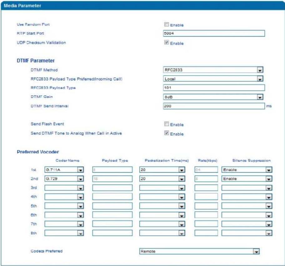
Figure 3.10-2 Configuration Interface for Media Parameters
Explanation of media parameters:
| Use Random Port | If this parameter is enabled, the gateway will choose a port at random as the start port for RTP. |
| RTP Start Port | Default RTP start port is 8000 |
| DTMF Method | Include SINGAL, INBAND and RFC2833 |
| RFC2833 Payload Type | Payload value, default value is 101 |
| DTMF Gain | Default value is 0 DB |
| DTMF Send Interval | The interval for sending DTMF signal. The default value is 200ms. |
| Send Flash Event | If this parameter is enabled, the gateway will send flash event to remote terminal, and thus user does need to handle it locally |
| Coder Name | The gateway supports G729, G711U, G711A and G723. When outgoing calls are made, G.729 will be used. |
| Payload Type | Each kind of coding has a unique load value in reference to RFC3551. |
| Packetization Time | The time for voice packaging |
| Rate | Voice data flow rate defaulted by system. |
| Silence Suppression | Default value is ‘disabled’. If this parameter is enabled, VoIP transmission bandwidth can be saved, and meanwhile network congestion can be avoided. |
3.8.3 SIP Parameters
SIP Parameter
SUBSCRIBE for MWI(Message Waiting Indicator)
MWI Subscription Expires(Default: 3800)
Voicemail User ID
Visual MWI Type
RFC3407 Support
IP-to-IP Call
URI includes "user=phone"
INVITE with "P-Preferred-Identity" Header (RFC3325)
Only Accept Calls from ACL(SIP Server or IP Trunk)
Anonymous Call
Reject Anonymous Call
as Ending Dial Key
Escape
Send # when First Dial Number is "
Value of "Refer To" refers to "Contact"
Third Party Do Not Send 18x Response
REFER Delay
Send BYE when Recv REFER Response(Unattended)
Send New REGISTER when Recv 423 Response
Cseq Start with 1
Forbid Invalid m=line in relNVITE
Call Confirm Tone
RTP Mode in SDP when Call Holding
Support Call Waiting of Huawei IPPBX
Accept Orphan 200 Ok
Called Number Preferred
Caller-ID Preferred
Report SDP Whatever
18x Response Preferred
FlashHook Operation Mode
Wait Dial Time
Attended Transfer Trigger
Domain Query Type
Domain Re-resolution Interval(0 means disable)
DNS Cache
Enable
3800 5
NEON
Enable
Enable
Enable
Enable
Enable
Enable
Enable
Enable
Enable
Enable
Enable
Enable
Enable
Enable
Enable
Enable
Enable
Enable
sendonly
Enable
Enable
Request-Line From Header
Enable
18x Response with SDP Mode three
5 s
Flashhook+4
A Query 0 min
Enable
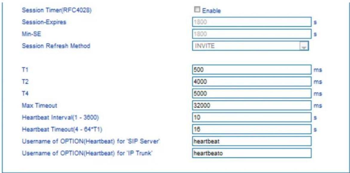
Figure 3.10-3 SIP Parameter Configuration Interface
Explanation of SIP parameters:
| SUBSCRIBE for MWI (Message Waiting Indicator) | You will be notified when ‘voicemail message waiting indicator’ is enabled. |
| MWI Subscription Expires | MWI subscription expiry time; default value is 3600s. |
| Voicemail User ID | The user ID for access to voicemail box |
| RFC3407 Support | Whether to enable RFC3407 support. |
| IP-to-IP Call | If this parameter is enabled, user can dial IP address through a phone to call destination gateway. |
| URI Includes user=phone | If this parameter is enabled, ‘user=phone’ will be contained in URI. When calls are routed to PSTN network, the called number will be got from user name. Default value is ‘not enable’. |
| INVITE with “P-Preferred-Identity” Header (RFC3325) | If this parameter is enabled, ‘P-Preferred-Identity’ Header will be added in INVITE message for anonymous call (Support RFC3325). |
| Only Accept Call from ACL (SIP server or IP Trunk) | If this parameter is enabled, the gateway only accepts incoming call from SIP server only. Default value is ‘not enable’. |
| Anonymous Call | If this parameter is enabled, ‘anonymous’ will be included in SIP message. |
| Reject Anonymous Call | If this parameter is enabled, all anonymous calls will be rejected. Default value is ‘not disable’. |
| # as ending Dial Key | ‘#’ is used as the end mark for dialing. |
| # Escape | If this parameter is enabled, ‘#’ is considered as a digit of th number that is dialed. |
| Value of “Refer To” refers to "Contact" | If this parameter is enabled, ‘contract header’ needs to be filled in in the ‘refer to’ field of a SIP message. |
| Third Party Do Not Send 18x Response | If this parameter is enabled, the third party will not send 18x response during a attended transfer. |
| Send BYE when Recv REFER Response (unattended) | If this parameter is enabled, the third party will send BYE to release session after receiving REFER during a blind transfer. |
| Send New REGISTER when Recv 423 Response | If this parameter is enabled, the value of ‘expires’ header will be automatically updated and REGISTER will be re-sent after receiving of 423 response. |
| Implicit Subscribe | If this parameter is enabled, the gateway will accept implicit subscription. |
| CSeq Start with 1 | If this parameter is enabled, the value of CSeq starts with ‘1’. |
| Forbid Invilad m=line in relNVITE | If this parameter is enabled, the gateway will prevent ‘invilad m=line’ from being carried in the SDP of re-INVITE. |
| RTP Mode in SDP when Call Holding | Use ‘sendonly ‘ or ‘inactive’ as RTP mode during call holding. |
| Support Call Waiting of Huawei IPPBX | If this parameter is enabled, the gateway will support call waiting of Huawei IPPBX. |
| Accept Orphan 200 OK | If this parameter is enabled, the gateway will support different ‘to-tag 200 OK’ in a INVITE session |
| Domain Query Type | There are two modes: A QUERY and SRV QUERY. Default is ‘A QUERY’. |
| Domain Re-resolution Interval | Default 0: forbidden |
| DNS cache | If this parameter is enabled, the gateway will cache the DNS query results. |
| Early Media | Support the receiving of Early Media. |
| PRACK(RFC3262) | Support reliable transmission of provisional response |
| PRACK Only for 18x with SDP | Send PRACK only when there’s SDP in 18x response |
| Early Answer | If this parameter is enabled, SDP will be contained in 18x |
| Session Timer (RFC4028) | Whether to enable ‘session timer’, default value is ‘ no’. |
| Session-Expires | The Session-Expires header field conveys the session interval for a SIP session. |
| Min-SE | Min-SE header field indicates the minimum value for the session interval. |
| T1 | T1 timer of SIP protocol, default is 500ms |
| T2 | T2 timer of SIP protocol, default is 400ms |
| T4 | T4 timer of SIP protocol, default is 500ms |
| Max Timeout | The max timeout of sending or receiving; default is 32s |
| Heartbeat Interval | Default is 10s. |
| Heartbeat Timeout | Default to 16s |
| Username of OPTION(Heartbeat) for “SIP Server” | The user ID part of OPTION SIP message in the heartbeat request for SIP server |
| Username of OPTION(Heartbeat) for “IP TRUNK” | The user ID part of OPTION SIP message in the heartbeat request for IP trunk |
Voicemail instructions:
How the voicemail works in the VGW-X20FS SERIES gateway together with Elastix.
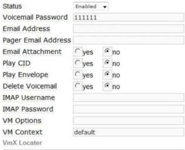
1) After the gateway is registered to Elastix server, enable the voicemail function in Elastix for the corresponding extension number and then set password shown below:
Voicemail & Directory
Elastix Voicemail Configuration Interface
2) Check feature code in Elastix and change it if necessary. Its default feature code setting is as follows:
Voicemail
Dial Voicemail
My Voicemail
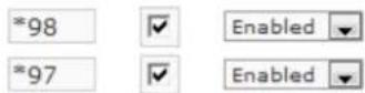
Elastix Voicemail Setting
On the Web interface of VGW-X20FS SERIES, click Advanced → SIP Parameter in the navigation tree and then enter voicemail User ID.

VoiceMail Setting in SIP Parameter
3) Set ringing time in Elastix. Elastix will prompt user to leave a message after the corresponding extension rings 15 seconds (by default). Then the Elastix sever will record the message. Related setting is shown as follows:
Voicemail
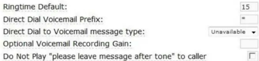
Voicemail Setting
4) Dial *200# on the extension which is connected to VGW-X20FS SERIES, then dial voicemail user ID and enter password for authentication. After that, user will hear a voice message.
3.8.4 Fax Parameter
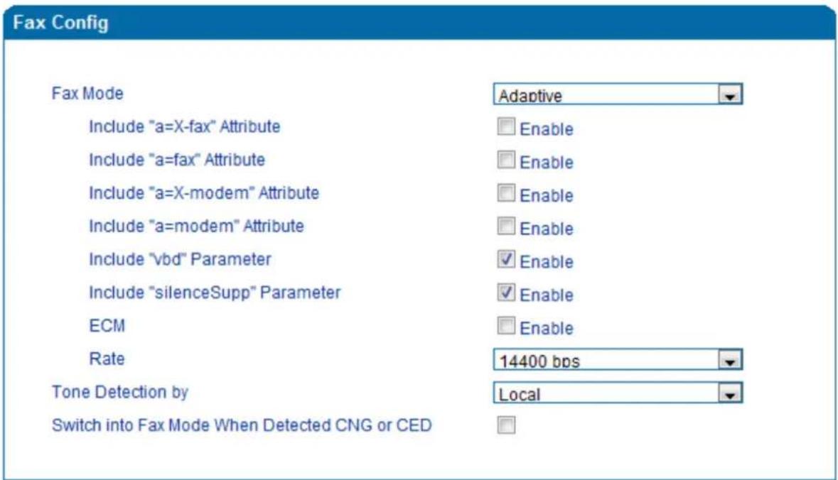
Figure 3.10-4 Configuration Interface for Fax Parameter
Explanation of fax parameters:
| Fax Mode | There are four fax modes: T.38, T.30 (Pass-through), Modem and Adaptive. |
| Include “a=X-fax” Attribute | If this parameter is enabled, “a=X-fax” attribute will be carried in SDP. |
| Include “a=fax” Attribute | If this parameter is enabled, “a=fax” attribute will be carried in SDP. |
| Include “a=X-modem” Attribute | If this parameter is enabled, “a=X-modem” attribute will be carried in SDP. |
| Include “a=modem” Attribute | If this parameter is enabled, “a=modem” attribute will be carried in SDP. |
| ECM | Whether to enable ‘Error Correction Mode’. |
| Rate | The rate of sending or receiving fax |
| Tone Detection by | Fax sound is detected by caller and callee automatically. |
3.8.5 Digit Map
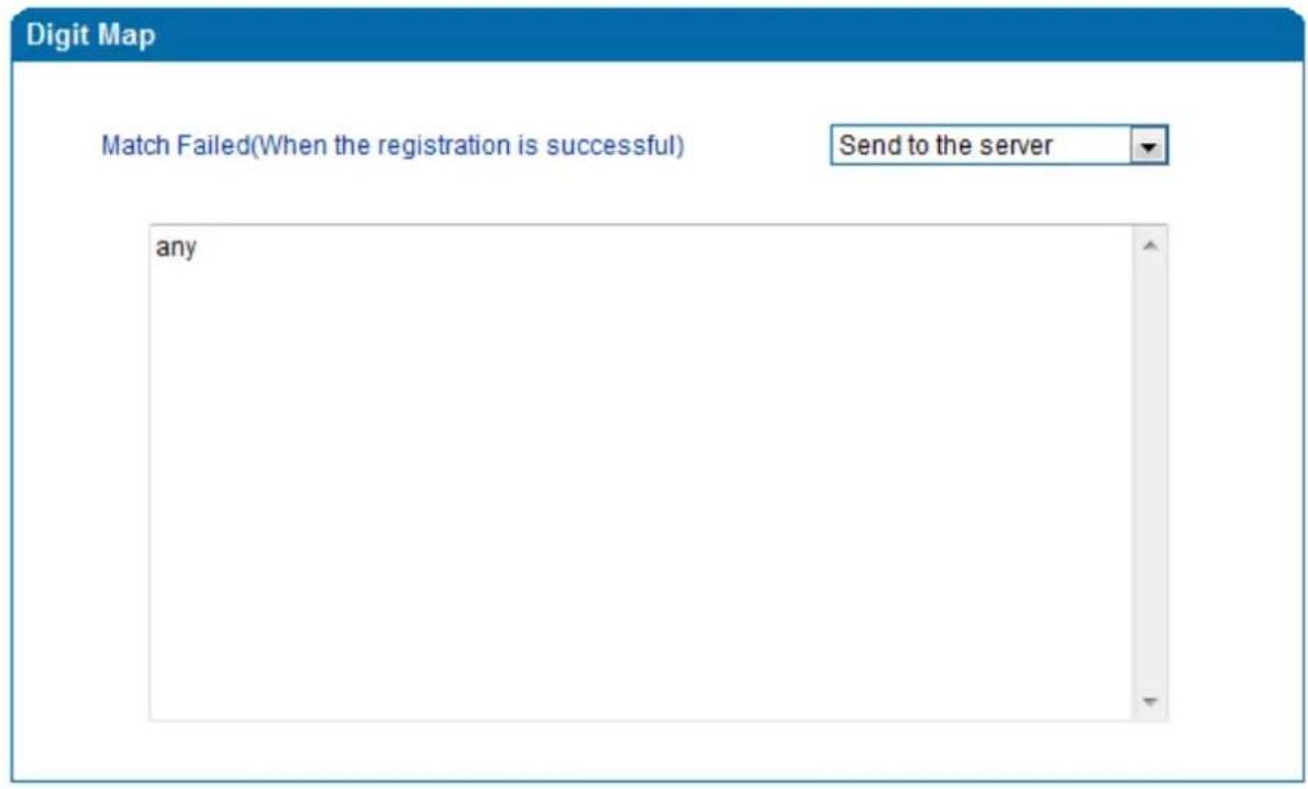
Figure 3.10-5 Digit Map
Digit Map Syntax
| Supported objects | Digit | 0-9 |
| T | Timer | |
| DTMF | A digit, a timer, or one of the symbols of A, B, C, D, #, or *. | |
| Range | [] | One or more DTMF symbols enclosed in the [], but only one DTMF symbol can be selected. |
| Range | () | One or more expressions enclosed the(), but only one can be selected. |
| Separator | | | Separated expressions or DTMF symbols. |
| Subrange | - | Two digits separated by hyphen (-) which matches any digit between n and including the two. |
| Wildcard | x | Matches any digit of 0 to 9 |
| Modifiers | . | Matches 0 or more times of the preceding element |
| Modifiers | ? | Matches 0 or 1 times of the preceding element |
Examples:
(13 | 15 | 18)xxxxxxxxx
Matches the phone numbers with stating digits as 13, 15 or 18 and the left nine digits as any of 0 to 9.
3.8.6 Feature Codes
Please make reference to 2.7 Description of Feature Codes and the following table.
| Inquiry LAN port IP address | Dial*158# to obtain device WAN port IP address |
| Inquiry WAN port IP address(For VGW-420FS/VGW-820FS only) | Dial*159# to obtain device WAN port IP address |
| Inquiry Phone Number | Dial*114# to obtain port account |
| Inquiry PortGroup Number | Dial *115# to obtain port group number |
| Setting IP Mode | *150*0#, means pppmodem, *150*1#, means static IP, *150*2#, means obtain IP address by DHCP, *150*3#, means pppoe. |
| Network Work Mode | *157*0#, set network work mode to routing mode; *157*1#, set network work mode to bridge mode |
| Configure IP Address | *152*+IP, set gateway IP address |
| Network subnet mask configure | *153*+subnet mask, set gateway subnet mask |
| Network Gateway Configure | *156*+gateway IP, set gateway |
| Renew DHCP | *193#, set dynamic IP again |
| Access Web by Wan in Rout Mode | Allow access web through WAN port: *160*1#; don't allow access web through WAN port: *160*0# |
| Reset Basic Configuration | Dial *165*000000# to restore default username/password and network configuration |
| Reset Factory Configuration | *166*000000#, reset factory |
| Restart Device | *111#, restart device |
| Call holding | During a call, dial*# into call hold. (Recovery the call through hook flash or *#) |
| Call by IP | Directly dial the end user IP to call |
| Call Waiting Activate | *51#, enable call waiting function |
| Call Waiting Deactivate | *50#, forbid call waiting function |
| Blind Transfer | If the call transfer to 801, first hook flash and then dial the * 87 * 801# |
| Call Forward Unconditional Activate | *72*+ phone number#, transfer the call from the phone number |
| Call Forward Unconditional Deactivate | *73#, forbid call forward unconditional |
| Call Forward Busy Activate | *90*+ forward busy number# |
| Call Forward Busy Deactivate | *91#, forbid call forward busy |
| Call Forward No Reply Activate | *92*+ forward no reply number# |
| Call Forward No Reply Deactivate | *93#, close this function |
| Do Not Disturb Activate | *78#, enable DND function |
| Do Not Disturb Deactivate | *79#, close DND function |
| Dial Voicemail | *200#, visit voice mail box |
3.8.7 System Parameter
System parameters include: STUN, NTP, Provision, EB parameter and Telnet.
1) STUN: STUN (Simple Traversal of UDP over NATs) is a lightweight protocol that allows applications to discover the presence and types of NATs and firewalls between them and the public Internet. It also provides the ability for applications to determine the IP addresses allocated to them by the NAT. STUN works with many existing NATs, and does not require any special behavior from them. STUN doesn't support TCP connection and H.323.
2) NTP: Network Time Protocol (NTP) is a computer time synchronization protocol.
3) Provision: Provision is used to make the gateway automatically upgrade with the latest firmware stored on an http server an ftp server or a tftp server.
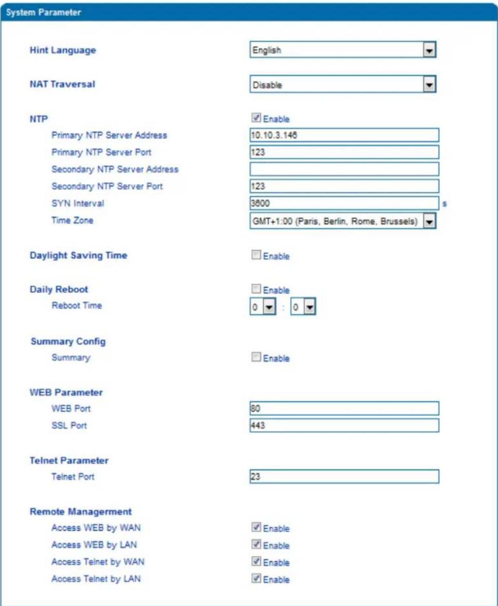
Figure 3.10-7 Configuration Interface for System Parameters
Explanation of related parameters:
| Hint Language | IVR language of the gateway |
| NAT Traversal | User can choose ‘Disable’, ‘STUN’, ‘static NAT’ and ‘dynamic NAT’. |
| NTP | To Enable or disable NTP |
| Primary NTP server address | The IP address of primary NTP server; default IP address is us.pool.ntp.org. |
| Primary NTP server port | The service port of primary NTP server; Default port is 123. |
| Secondary NTP server address | The IP address of secondary NTP server ; Default IP address is 18.145.0.30 |
| Secondary NTP server port | The service port of secondary NTP server; Default port is 123 |
| SYN Interval | The interval to synchronize the time of the VGW-X20FS SERIES. Default value is 3600s. |
| Time Zone | The time zone of the gateway; Default configuration is United States central time, Chicago. |
| Daylight Saving Time | Enable or disable daylight saving time |
| Daily Reboot | Whether to enable daily reboot |
| Reboot time | The time to reboot the gateway daily |
| Web Port | The web port of the gateway; Default port is 80 |
| Telnet port | Listening port of telnet service; Default port is 23 |
| Access Web by WAN | Enable or disable ‘Access web service from WAN’ |
| Access Web by LAN | Enable or disable ‘Access web service from LAN’ |
| Access Telnet by WAN | Enable or disable ‘telnet service from WAN’ |
| Access Telnet by LAN | Enable or disable ‘telnet web service from LAN’ |
3.8.8 Action URL
Action URL can be used as a means to allow the VoIP platform to learn about the VGW-X20FS SERIES's status. It transmits data via GET request over the HTTP protocol. The VGW-X20FS SERIES is an HTTP client. At HTTP server side, GET request must be processed by the VoIP platform. Thus, the purpose is achieved.
| Action URL Configuration | |
| Event | Action URI |
| Startup | |
| Offhook | |
| Onhook | |
| Incoming Call | |
| Outgoing Call | |
| Call Build | |
| Call Terminate | |
| Register Status | |
| Heartbeat | |
| Heartbeat Interval | 10 s |
Figure 3.10-8 Action URL
3.9 Call & Routing
3.9.1 Wildcard Group
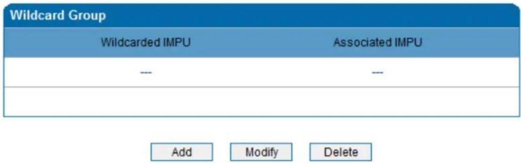
Figure 3.11-1 Wildcard Group
3.9.2 Port Group
On the Port Group interface, user can group several ports together and then set a strategy for port selection of the group. Parameters of port group include registration, primary display name, primary SIP user ID, primary authentication ID and password, secondary display name, secondary SIP user ID, secondary authentication ID and password, off-hook auto dial, auto dial delay time, port select and so on.
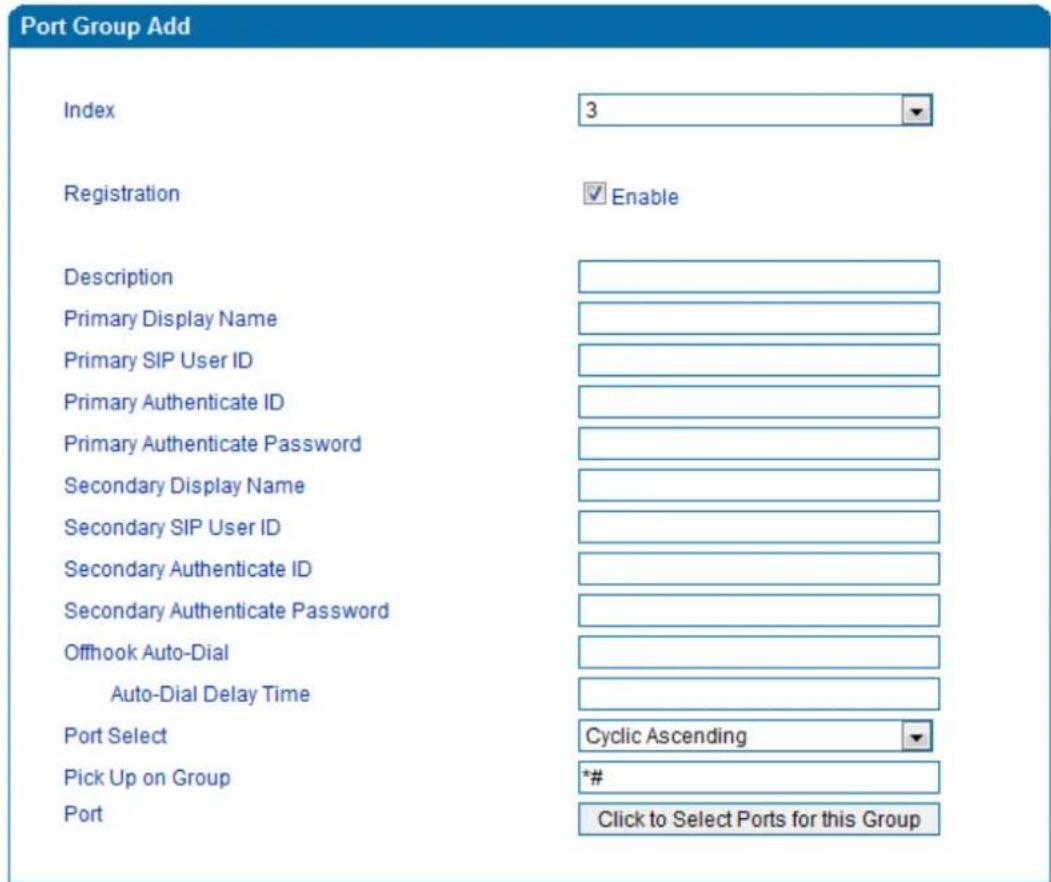
Figure 3.11-2 Configuration Interface for Port group
Explanation of related parameters
| Index | The No. of the port group; it uniquely identifies a route, ranging from 0 to 7. |
| Description | |
| Primary/Secondary Display Name | Port group display is used in SIP message like the examples below: INVITE sip:bob@biloxi.com SIP/2.0 Via:SIP/2.0/UDPpc33.atlanta.com;branch=z9hG4bK776asdhds Max- Forwards: 70 To: BobFrom: Alice;tag=1928301774 Here Bob and Alice is the display |
| Primary/Secondary SIP User ID | User account information, provided by VoIP service provider (ITSP). Usually in the form of digit similar to phone number or actually a phone number. |
| Primary/Secondary Authenticate ID | SIP service subscriber's authenticated ID -- It can be identical to or different from SIP User ID. |
| Primary/Secondary Authenticate Password | Password of SIP user ID |
| Offhook Auto-Dial | To enter offhook auto-dial number |
| Auto-dial Delay time | How long auto-dialing will be delayed |
| Port Select | It specifies the policy for selecting a port for ringing in the port groupAscending: the gateway always selects a port from the minimum number.Cyclic ascending: the gateway always selects a port from a number next to the number selected last time. If the maximum number was selected last time, the next selected number is the minimum number. The sequence moves in cycles like this.Descending: the gateway always selects a port from the maximum number.Cyclic descending: the gateway always selects a port from a number next to the number selected last time. If the minimum number was selected last time, the next selected number is the maximum number. The sequence moves in cycles like this.Group ring: all ports ring at the same time |
| Pickup UP on group | When one port rings, user can dial "*#" to pick up the call from other ports under the same port group. |
| Port | Select ports for this port group |
3.9.3 IP Trunk
A peer-to-peer VoIP call occurs when two VoIP phones communicate directly over IP network without IP PBXs between them. IP trunk helps establish peer-to-peer call between gateway and VoIP phones. IP trunk will be used in routing configuration.
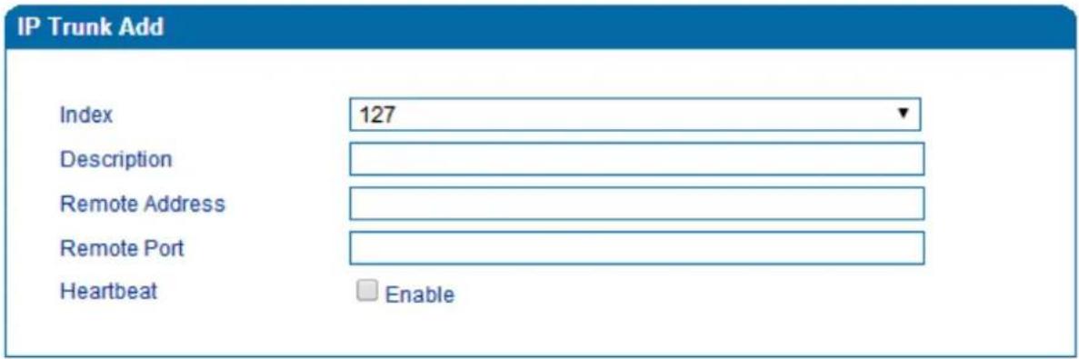
Figure 3.11-3 IP Trunk Configuration Interface
Explanation of related parameters:
| Index | The no. of the IP trunk ranging from 0 to 127. |
| Description | The description of the IP trunk is used to identify the IP trunk. |
| Remote Address | IP address or domain name of peer device |
| Remote Port | SIP port of peer device |
| Heartbeat | Whether to enable the ‘Heartbeat’ function for the IP trunk. Default value is ‘not enable’. If heartbeat is enabled, the gateway will send “OPTION” to peer device. |
3.9.4 Routing Parameter
This parameter determines whether a call is routed before or after manipulation.
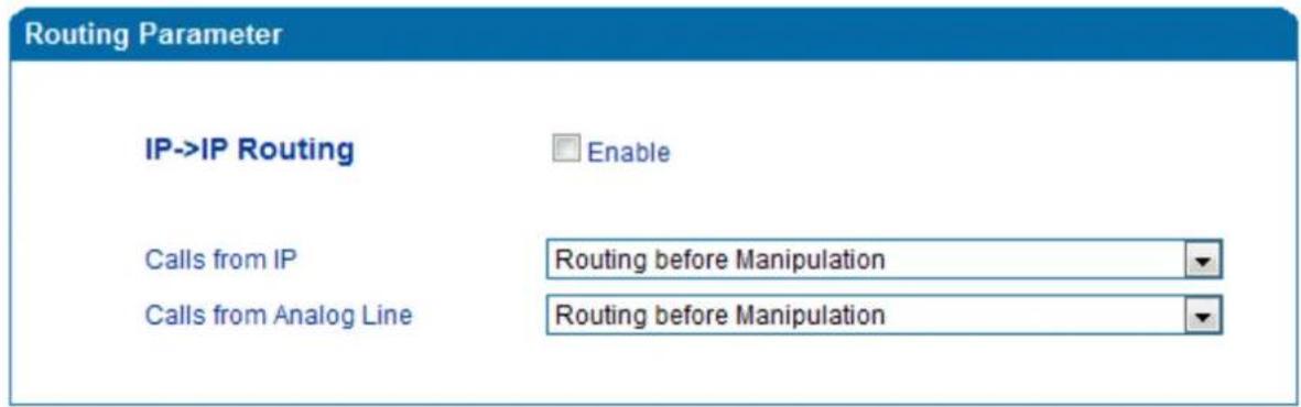
Figure 3.11-4 Configuration Interface for Routing Parameter
3.9.5 IP -> Tel Routing
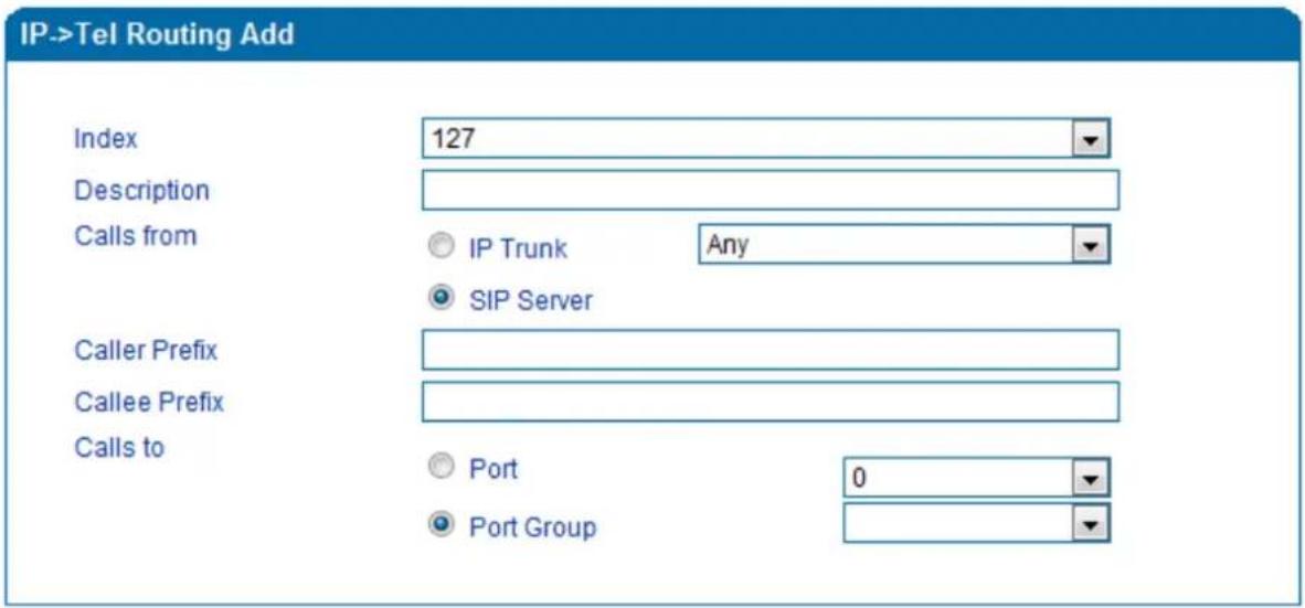
Figure 3.11-5 Configuration Interface for IP-Tel Routing
Explanation of related parameters:
| Index | IP →Routing priority: from 0 to127; 0 is the highest priority. |
| Description | It is used to identify the IP → routing |
| Calls from | IP Trunk or SIP Server; ‘any’ means any IP addresses |
| Caller Prefix | The prefix of the caller number, which helps match routing exactly. its length is less than or equal to the caller number. For example, if caller number is 2001, the caller prefix can be 200 or 2. ‘any’ means the prefix matches any caller number. |
| Callee Prefix | The prefix of the called number, which helps match routing exactly. Its length is less than or equal to the called number. If the called number is 008675526456659, the called prefix can be 0086755 or 00., “any” means the prefix matches any called number |
| Calls to | Which port or port group to which calls are routed |
3.9.6 Tel-IP/Tel Routing
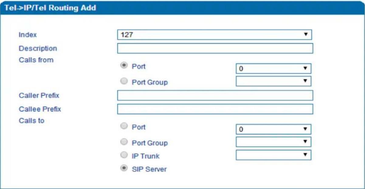
Figure 3.11-6 Configuration Interface for Tel-IP/Tel Routing
Explanation of related parameters:
| Index | The index of this Tel →IP/Tel routing, from 0 to 127. Each index cannot be used repeatedly. Routing priority: 0 is the highest priority. |
| Description | It is used to identify the routing |
| Calls From | Tel →IP calls are from a port or a port group |
| Caller Prefix | The prefix of the caller number, which helps match routing exactly. its length is less than or equal to the caller number. For example, if caller number is 2001, the caller prefix can be 200 or 2. ‘any’ means the prefix matches any caller number. |
| Callee Prefix | The prefix of the called number, which helps match routing exactly. Its length is less than or equal to the called number. If the called number is 008675526456659, the called prefix can be 0086755 or 00., “any” means the prefix matches any called number. |
| Calls to | Calls are routed to a port, port group, IP trunk or SIP server |
3.9.7 IP - IP Routing
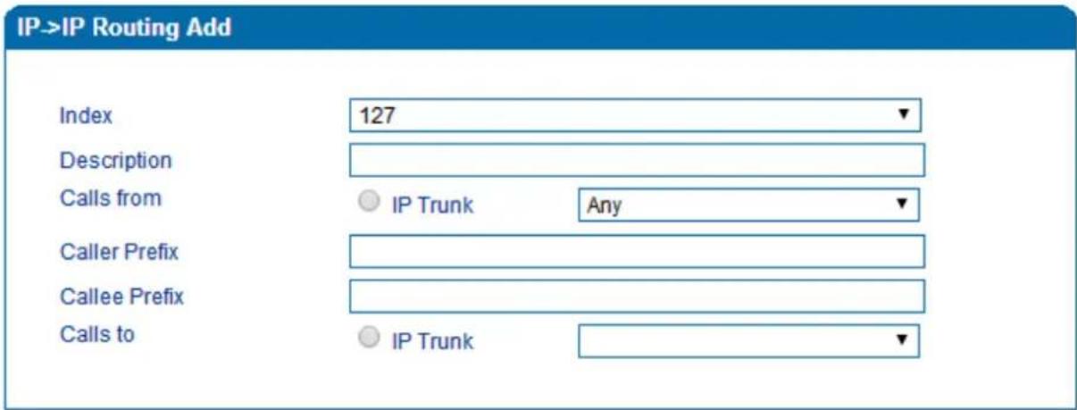
Figure 3.11-7 Configuration Interface for IP->IP Routing
Explanation of related parameters:
| Index | The index of this IP →IP routing, from 0 to 127. Each index cannot be used repeatedly. Routing priority: 0 is the highest priority. |
| Description | It is used to identify the routing |
| Calls From | Calls are from IP trunk. |
| Caller Prefix | The prefix of the caller number, which helps match routing exactly. its length is less than or equal to the caller number. For example, if caller number is 2001, the caller prefix can be 200 or 2. ‘any’ means the prefix matches any caller number. |
| Callee Prefix | The prefix of the called number, which helps match routing exactly. Its length is less than or equal to the called number. If the called number is 008675526456659, the called prefix can be 0086755 or 00.,“any” means the prefix matches any called number. |
| Calls to | Calls are routed to IP trunk |
3.10 Manipulation Configuration
Number manipulation refers to the change of a called number or a caller number during calling process when the called number or the caller number matches the preset rules.
3.10.1 IP -> Tel Callee
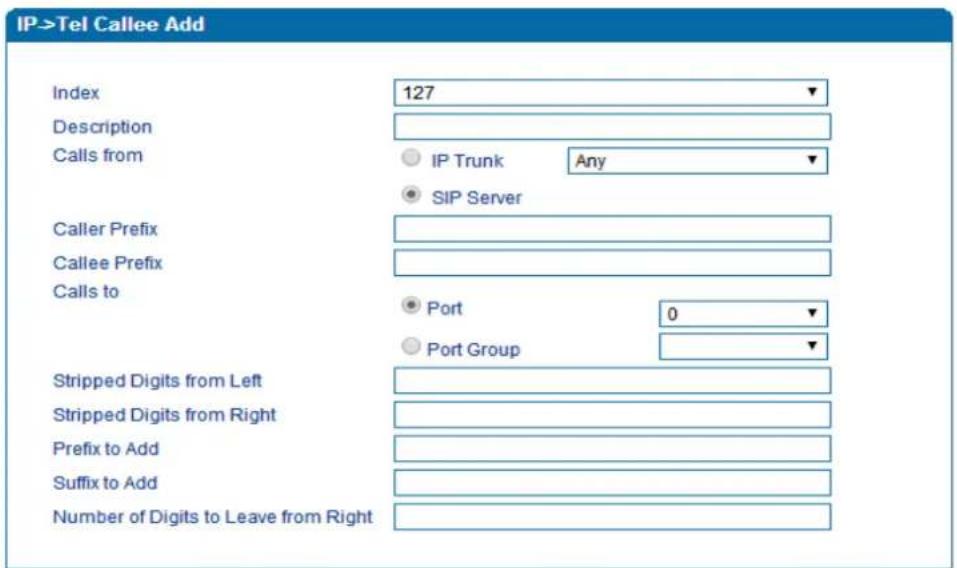
Figure 3.12-1 Add IP -> IP Callee
| Index | The index of this manipulation, from 0 to 127. Each index cannot be use repeatedly. 0 is the highest priority |
| Description | Name of this IP ->Tel manipulation name |
| Calls From | Determine the calls come from IP trunk or SIP server |
| Caller Prefix | Set a prefix for caller number. The prefix's length is less than or equal to that of the caller number, which helps to match routing. If caller number is 2001, the caller prefix can be 200 or 2. “any” means match any caller number. |
| Callee Prefix | Set a prefix for called number. The prefix's length is less than or equal to called number, which helps to match routing. If called number is 008675526456659, the called prefix can be 0086755 or 00., “any” means match any called number |
| Calls to | Determine the port or port group to which the call is routed. |
| Stripped Digits from Left | The number of digits which are lessened from the left of the callee number |
| Stripped Digits from Right | The number of digits which are lessened from the right of the callee number |
| Prefix to Add | The prefix added to the callee number after its digits are lessened. |
| Suffix to Add | The suffix added to the callee number after its digits are lessened. |
| Number of Digits to Leave from Right | The number of the retained digits which. are counted from the right of the callee number |
3.10.2 Tel -> IP/Tel Caller
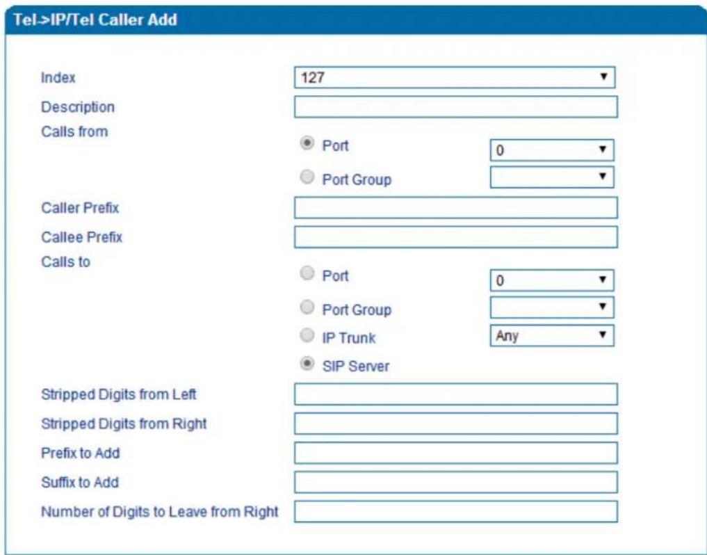
Figure 3.12-2 Add Tel -> IP Caller
Configuration parameters are the same as those of 'IP->Tel Callee'.
3.10.3 Tel-IP/Tel Callee
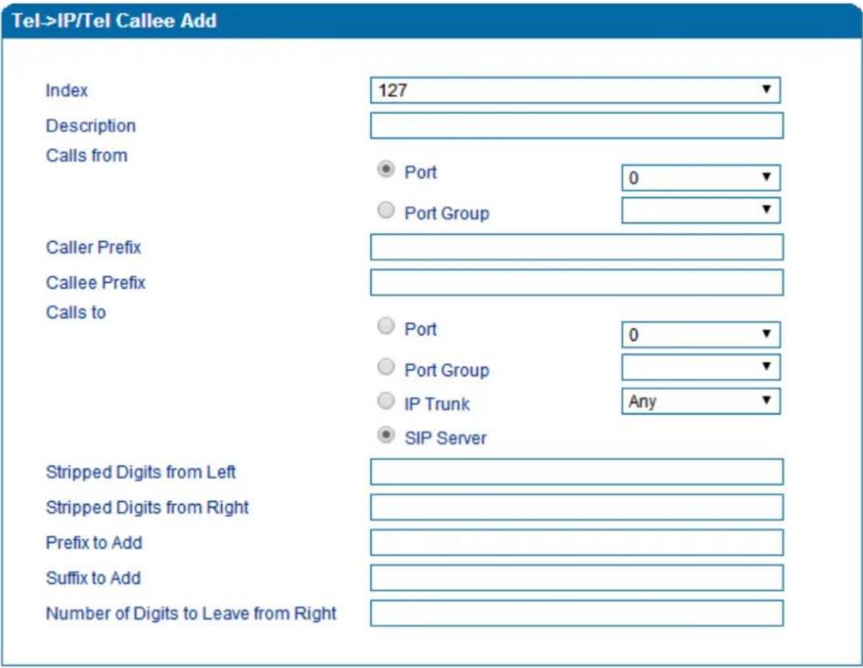
Figure 3.12-3 Add Tel-IP Callee
Configuration parameters are the same as those of 'Tel->IP Caller'.
3.11 Routing rule examples
3.11.1 Route any calls from any IP to specific port
After entering the Web interface, click Call & Routing → IP-Tel Routing in the navigation tree on the left, and then click Add to create a new routing rule.
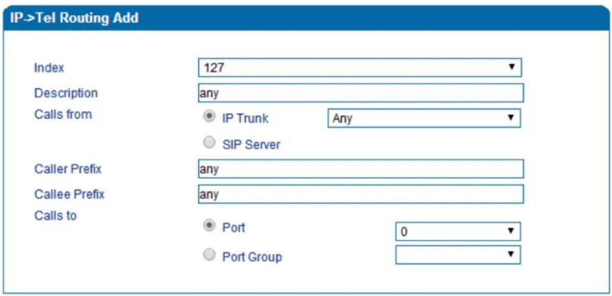

NOTES:
- 'any' in 'Callee Prefix' or 'Caller Prefix' means wildcard string.
In the example above, all calls will be routed to port 0 when the routing rule is matched.
3.11.2 Route any calls from any IP to specified port group
▶ Create port group
Before we can route calls to a port group, create the port group first as shown below. On the Call & Routing → Port Group, click Add to create a new port group.
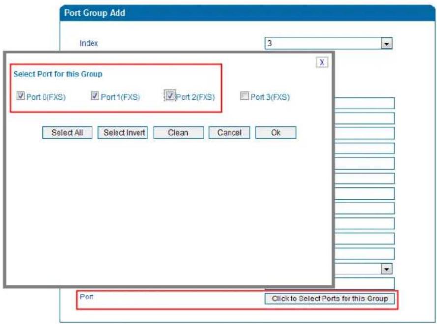
Port 0 to port 2 are assigned to port group 7.
▶ Route any calls to the port group
On the Call & Routing → IP-Tel Routing interface, click Add to create a new routing rule.
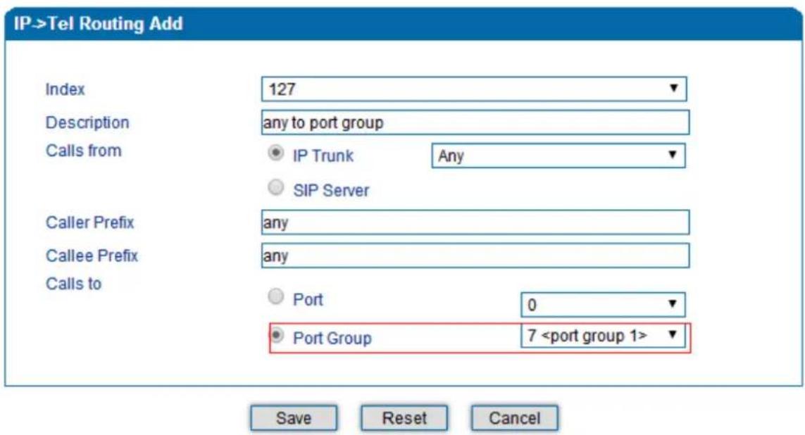
NOTES:
- 'any' in 'Callee Prefix' or 'Caller Prefix' means wildcard string.
As shown above, if the routing rule is matched, calls will be routed to port group 7.
3.11.3 Route any calls from any port to specific SIP IP trunk
Create IP Trunk on the Call & Routing → IP Trunk interface:
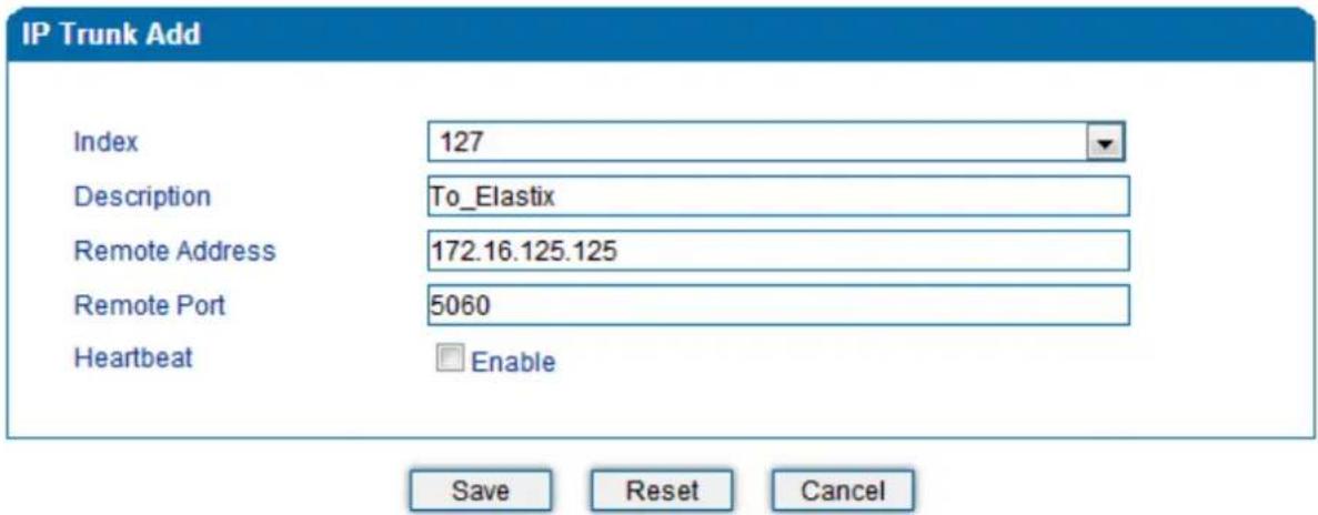
After IP Trunk is created, check the following configuration:
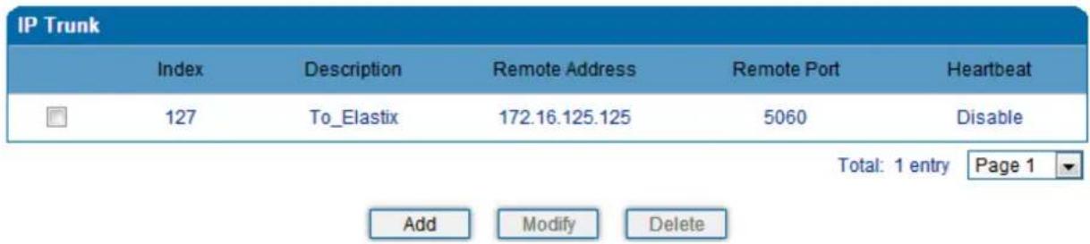
As shown above, the IP trunk is created, and the remote end IP address is 172.16.125.125, the SIP port is 5060.
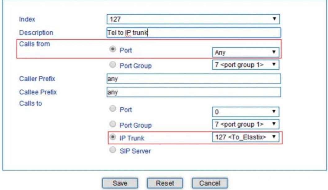
Create Tel -> IP routing rule
On the Call & Routing → Tel-IP Routing interface, click "Add" to create a new Tel → IP routing rule.
Tel->IP/Tel Routing Add
NOTES:
- 'any' in 'Callee Prefix' or 'Caller Prefix' means wildcard string.
All Tel calls from any caller number to any called number will be routed to IP trunk 127.
3.12 Maintenance
3.12.1 TR069
ACS URL (auto-configuration server URL address) is provided by service provider. The ACS URL generally starts with http:// or https://
Username and password are used for ACS authentication.
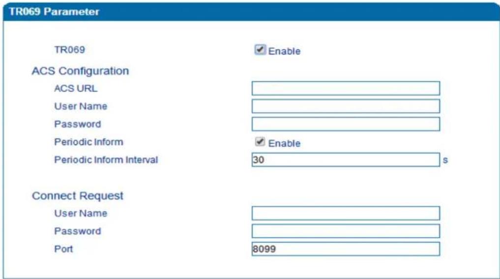
Figure 3.14-1 TR069 Parameters
3.12.2 SNMP (Simple Network Management Protocol)
SNMP Parameters:
• SNMP enable: to disable or enable the SNMP feature
• SNMP version: the VGW-X20FS SERIES gateway supports SNMP v1 and v2
• Community: the community name used to read through SNMP protocol
• Source: the IP address of SNMP server
SNMP Parameter
Snmp
Snmp Version

Enable
Community Configuration
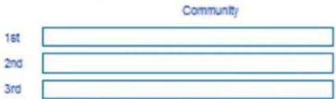
Note: Value of 'Source' is 'default' or IP Address(eg:192.168.1.1)!
Group Configuration
View Configuration
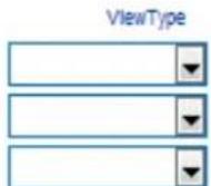
Note: Value style of "ViewSubtree" is "x.x.x.x.x" (multi-nodes) or ".x" (one node).
Access Configuration(v1/v2c)
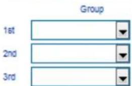
Note: The value of Read/Write/Notify references to 'ViewName' In View Configuration. Access Configuration is base on Group Configuration and View Configuration.
Trap Configuration
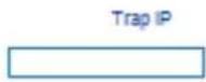
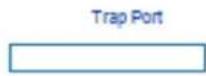
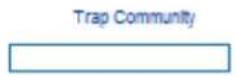
Figure 3.14-2 SNMP Parameters
User configuration is only available on SNMP v3.
SNMP Version
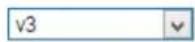
User Configuration

Notice: The length of AuthPassword and PrivacyPassword are more than 8!
Group configuration
Group: community group name which consist of character string.
Community: let community join the community group which configured above
Group Configuration

Trap configuration
Trap configuration is enabled to configure Trap Server IP and port. This setting is available for SNMP v2c and v1.
Trap Configuration

3.12.3 Syslog
Syslog is a standard for network device data logging. It allows separation of the software that generates messages from the system that stores them and the software that reports and analyzes them. It also provides devices which would otherwise be unable to communicate a means to notify administrators of problems or performance. There are 5 levels of syslog, including NONE, DEBUG, NOTICE, WARNING and ERROR.
The Signal Log includes the following traces which are defined in the system by default:
- SD, hardware debug
- SIP, SIP signaling trace
- STUN, STUN logs
- ECC, detail information of call control module
- RE, the common communication module for SCP and SIM
- SCP, the communication protocol between gateway and cloud server
The media log is include following traces which defined in system by default
- RTP, RTP stream info collection
- SIM, to output traces between gateway and remote SIM cards
The System Log is include following traces which mainly used by developer
- SYS, system log
- TIMER, system process
- TASK, system task process
- CFM, system process
- NTP
The Management Log is include following traces which defined in system by default
- CLI, command line
- TEL,
- LOAD, firmware upload
- SNMP
- WEB, embedded web server
- PROV, provisioning
Server Syslog:
When the gateway is registered to SIM Cloud server, the option will be changed to un-configurable and all logs to be stored on server.
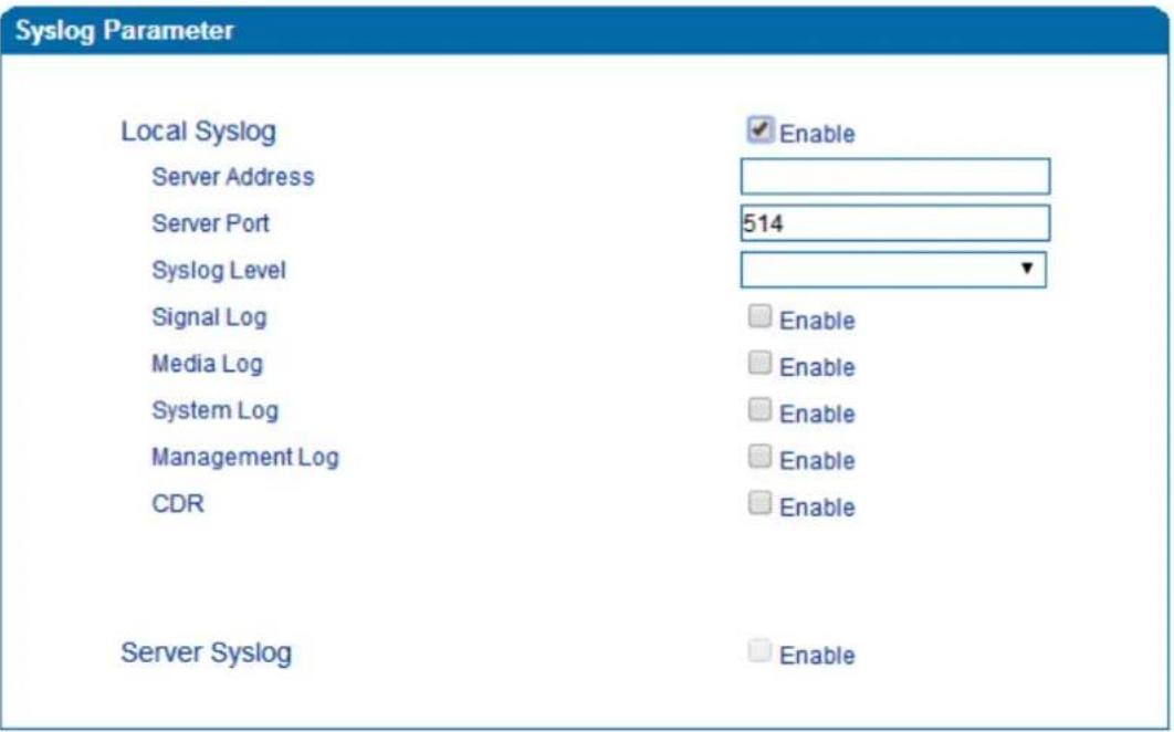
Figure 3.14-3 Syslog Parameter
Enable send CDR, and then send communication information to syslog server.
3.12.4 Provision
Provision is used to make the VGW-X20FS SERIES automatically upgrade with the latest firmware stored on an http server an ftp server or a tftp server.
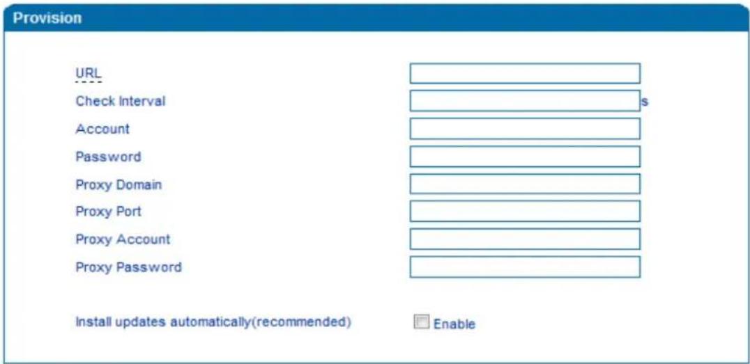
Figure 3.14-4 Provision
| URL | Provisioning server URL and supporting HTTP, TFTP, FTP |
| Check Interval | The interval to check the changes on the provisioning server |
| Account | Account for login provisioning server |
| Password | Account for login provisioning server |
3.12.5 Cloud Server
User can register the gateway to cloud server, and then the gateway will be managed by cloud server.
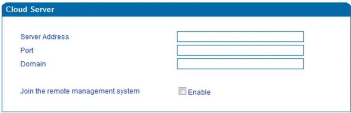
Figure 3.14-5 Cloud Server
Explanation of related parameters
| Server Address | The IP address or domain of the cloud server |
| port | The listening port of the cloud server |
| Password | Password for register with cloud server |
3.13 Security
3.13.1 WEB ACL
ACL (Access Control List) for Web is used to configure IP addresses (users) that are allowed to access the Web page of the gateway. The IP address list can't be null once ACL is enabled.
ACL
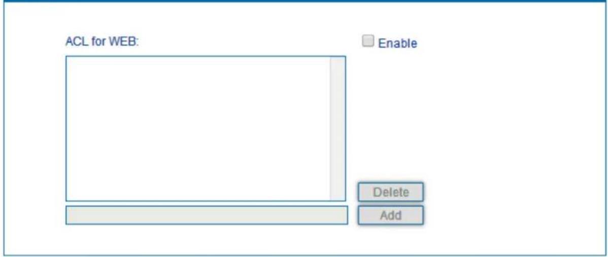
Figure 3.15-1 ACL for WEB
3.13.2 Telnet ACL
ACL (Access Control List) for Web is used to configure IP addresses (users) that are allowed to access the Telnet page of the gateway. The IP address list can't be null once ACL is enabled.
ACL for Telnet
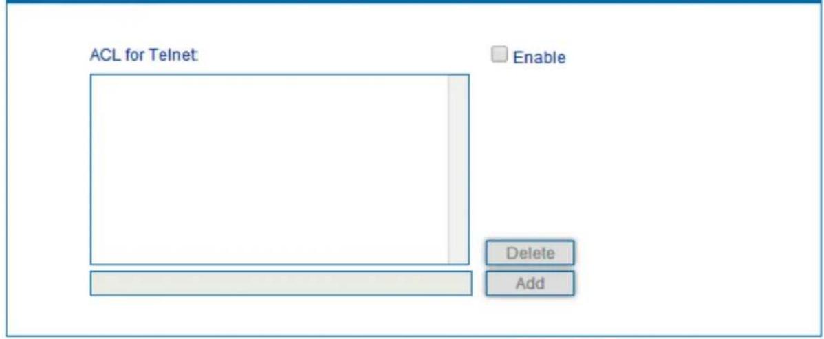
Figure 3.15-2 ACL for Telnet
3.13.3 Passwords
On the following interface user can configure or modify the username and password for access to the Web interface and the Telnet interface.

Note
Both the username and password of Web and Telnet are 'admin' and 'admin'.
Password Modification
Web Config
Old Web Username
Old Web Password
New Web Username
New Web Password
Confirm Web Password
admin
Telnet Config
Old Telnet Username
Old Telnet Password
New Telnet Username
New Telnet Password
Confirm Telnet Password
admin
Figure 3.15-3 Password Modification
3.14 Tools
3.14.1 Firmware upload
Firmware upload steps:
Step 1.
Check the current firmware version on the System Information page
| Current Software Version | IAD-4S 1.19.01.10 PCB 4 LOGIC 0 BIOS 1, 2016-02-19 10:06:41 |
| Backup Software Version | IAD-4S 1.19.01.10 PCB 4 LOGIC 0 BIOS 1, 2016-02-19 10:06:41 |
| DSP Version | MIPS_1_7 Nov 30 2015 17:18:14 |
| U-BOOT Version | 5 |
| Kernel Version | 4 |
| FS Version | 3.0.14 |
| Hint Language | English |
Figure 3.16-1 Firmware Version
Step 2.
Prepare firmware package. The most important is that the package must match with the existing version.
Package version consists of the following parts:
1.18.xx.xx
01/02 is vendor name
18 is hardware version, xx.xx is version number
Step 3.
Upload firmware, select the package from specific folder on the computer and click the Upload button.
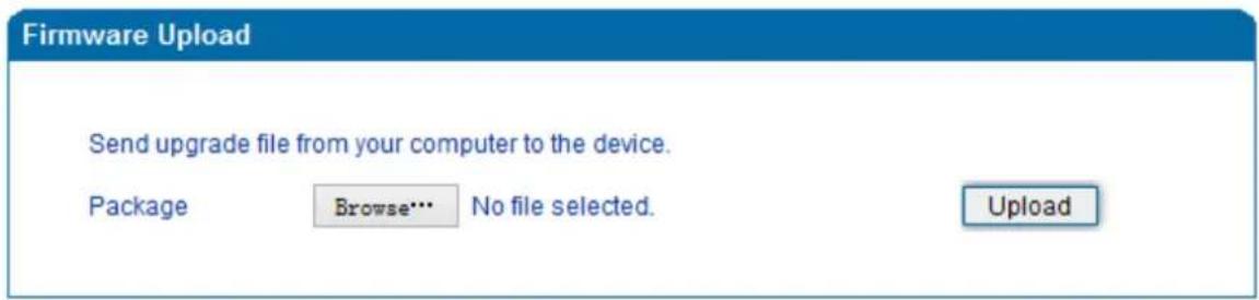
Figure 3.16-2 Firmware Upload
Step 4.
Keep waiting until it prompts 'Software loaded successfully!'
Prompt
Software loaded successfully!
Figure 3.16-3 Successful Firmware Upload
Step 5.
Reboot gateway. Refer to web page Maintenance->Device Restart
Restart
Click this button to restart the device.
Restart
Figure 3.16-4 Restart Gateway
3.14.2 Data Backup
The process data backup:
1) Click "Data Backup"
2) Click "Backup" to backup data to PC.

Figure 3.16-5 Data Backup
3.14.3 Data Restore
The processes of data restore:
Click 'Data Restore';
▶ Browse file, select data file.
Click 'Restore' and then import successfully; the device will restart automatically.
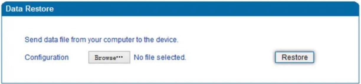
Figure 3.16-6 Data Restore
3.14.4 Ping Test
On the Tools → Ping Test interface, user can use Ping to check whether the network is working or not. Ping instructions:
1) Click 'Tools → Ping Test' on the navigation tree on the left;
2) Fill in IP address or domain whose connection needs to be checked, and click start.
If a message is received, it indicates that network connection is normal. Otherwise the network connection is faulty.
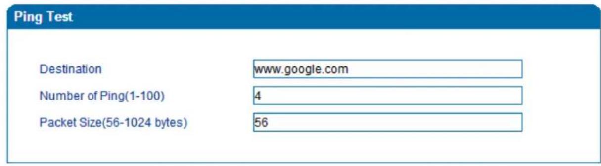

| Information | |
| Pinging www.google.com[Resolve: 173.194.127.240] with 56 bytes of data: Reply seq=0 from 173.194.127.240: bytes=56 time=20ms TTL=54 | |
Figure 3.16-7 Ping Test
3.14.5 Tracert Test
Tracert is a trace router used to track routing.
Tracert sends a sequence of Internet Control Message Protocol (ICMP) echo request packets addressed to a destination host. Determining the intermediate routers traversed involves adjusting the time-to-live (TTL), aka hop limit, Internet Protocol parameter. Frequently starting with a value like 128 (Windows) or 64 (Linux), routers decrement this and discard a packet when the TTL value has reached zero, returning the ICMP error message ICMP Time Exceeded.
Tracert works by increasing the TTL value of each successive set of packets sent. The first set of packets sent have a hop limit value of 1, expecting that they are not forwarded by the first router. The next set have a hop limit value of 2, so that the second router will send the error reply. This continues until the destination host receives the packets and returns an ICMP Echo Reply message.
Trace route uses the returned ICMP messages to produce a list of hops (which usually consists of routers and layer 3 switches) that the packets have traversed. The timestamp values returned for each router along the path are the delay (aka latency) values, typically measured in milliseconds for each packet.
Tracert introduce :
▶ Click 'Tracert Test' in the navigation tree;
▶Fill in IP address or domain whose route needs to be tracked, and then click start.
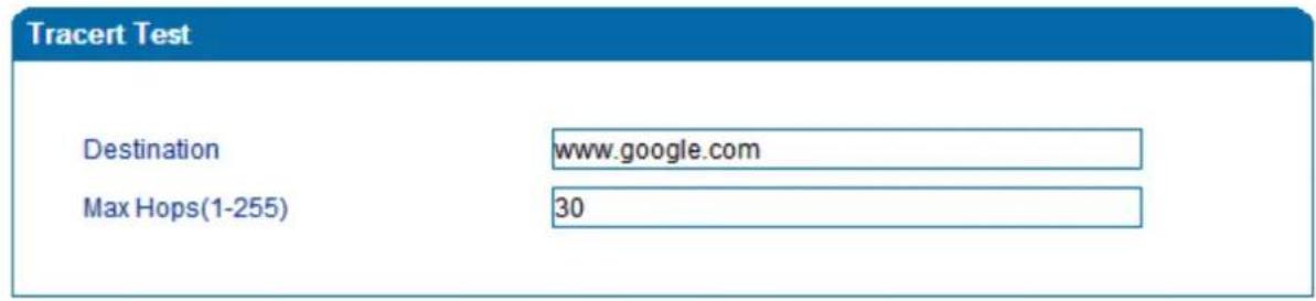

![Information Tracing route to www.google.com[Resolve: 173.194.127.240] over a maximum of 30 hops: 1 10 ms 172.16.1.1 2 1 ms 113.106.38.109 3 * Request timed out. 4 10 ms 121.34.242.234 5 10 ms 202.97.33.242 6 10 ms 202.97.60.50 7 * Request timed out. 8 * Request timed out.](/content/2026/05/760921/images/e1c1ab554a439bbf0e45afa4928902c7b31b7ecd413bff045a5b5975fba38fd3.jpg)
Figure 3.16-8 Tracert Test
3.14.6 Outward Test
Outward test enables user to diagnose the physical phone lines which follow GR909 standards. To start outward test, select the ports to be tested and click 'start'. Testing will take a few minutes.
| Outward Test | ||||||
| Port | Enable | Loop Open | H.F. DC Voltage(V) | H.F. AC Voltage(mV) | Tip/Ring Short | Result |
| 0 | ||||||
| 1 | ||||||
| 2 | ||||||
| 3 | ||||||
| 4 | ||||||
| 5 | ||||||
| 6 | ||||||
| 7 | ||||||
| Options: □ Test All Ports | ||||||
Figure 3.16-9 Outward Test
Test results
OK: The analog phone set and phone line are working well
Failed: Analog phone could not be connected to FXS port or there's something wrong with the phone set
3.14.7 Network Capture
Network capture is a very important diagnostic tool for maintenance. It can be used to capture data packages of the available network ports.
Default Setting is PCM capture
PCM capture helps to analysis voice stream between analog phone and DSP chipset.
▶ To enable PCM capture
- Select 'PCM' on Network Capture page
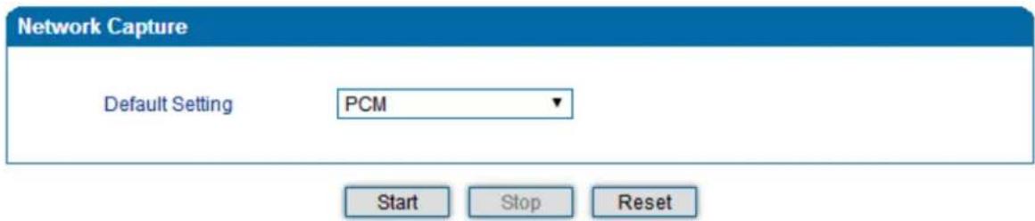
- Click "Start" to enable PCM capture
◆ Dialing out through gateway and start talking for a short, and then hanging up the call. - Click 'Stop' to disable network capture
- Save the capture file to local computer
The capture is named to 'capture(x).pcap', x is serial number of capture and will be added 1 next time.
The sample of PCM capture is shown below:
| No. | Time | Source | Destination | Protocol | Length Info | |
| 1 | 0.000000 | Motorola_1c:1d:1e | Cimsys_33:44:55 | CSM_ENCAPS | 104 --> 0x0021 | Ch: 0xFFFF, Seq: 8 (From Host) |
| 2 | 0.000131 | Cimsys_33:44:55 | Motorola_1c:1d:1e | Ethernet | 20 Ethernet II[Malformed Packet] | |
| 3 | 0.000245 | Cimsys_33:44:55 | Motorola_1c:1d:1e | CSM_ENCAPS | 44 --> 0x0021 | Ch: 0xFFFF, Seq: 11 (From Host) |
| 4 | 1.320893 | Motorola_1c:1d:1e | Cimsys_33:44:55 | CSM_ENCAPS | 104 --> 0x0e00 | Ch: 0x0003, Seq: 0 (From Host) |
| 5 | 1.321022 | Cimsys_33:44:55 | Motorola_1c:1d:1e | Ethernet | 20 Ethernet II[Malformed Packet] | |
| 6 | 1.321129 | Cimsys_33:44:55 | Motorola_1c:1d:1e | CSM_ENCAPS | 30 --> 0x0e00 | Ch: 0x0003, Seq: 1 (From Host) |
| 7 | 1.329890 | Motorola_1c:1d:1e | Cimsys_33:44:55 | CSM_ENCAPS | 104 --> 0x0e01 | Ch: 0x0003, Seq: 1 (From Host) |
| 8 | 1.330010 | Cimsys_33:44:55 | Motorola_1c:1d:1e | Ethernet | 20 Ethernet II[Malformed Packet] | |
| 9 | 1.330093 | Cimsys_33:44:55 | Motorola_1c:1d:1e | CSM_ENCAPS | 30 --> 0x0e01 | Ch: 0x0003, Seq: 2 (From Host) |
| 10 | 1.330472 | Motorola_1c:1d:1e | Cimsys_33:44:55 | CSM_ENCAPS | 104 --> 0x0802 | Ch: 0x0003, Seq: 2 (From Host) |
| 11 | 1.330566 | Cimsys_33:44:55 | Motorola_1c:1d:1e | Ethernet | 20 Ethernet II[Malformed Packet] | |
| 12 | 1.330639 | Cimsys_33:44:55 | Motorola_1c:1d:1e | CSM_ENCAPS | 30 --> 0x0802 | Ch: 0x0003, Seq: 3 (From Host) |
| 13 | 1.330820 | Motorola_1c:1d:1e | Cimsys_33:44:55 | CSM_ENCAPS | 104 --> 0x0803 | Ch: 0x0003, Seq: 3 (From Host) |
| 14 | 1.330903 | Cimsys_33:44:55 | Motorola_1c:1d:1e | Ethernet | 20 Ethernet II[Malformed Packet] | |
| 15 | 1.330989 | Cimsys_33:44:55 | Motorola_1c:1d:1e | CSM_ENCAPS | 30 --> 0x0803 | Ch: 0x0003, Seq: 4 (From Host) |
| 16 | 1.337791 | Motorola_1c:1d:1e | Cimsys_33:44:55 | CSM_ENCAPS | 104 --> 0x9010 | Ch: 0x0003, Seq: 4 (From Host) |
| 17 | 1.337996 | Cimsys_33:44:55 | Motorola_1c:1d:1e | Ethernet | 20 Ethernet II[Malformed Packet] | |
| 18 | 1.338033 | Cimsys_33:44:55 | Motorola_1c:1d:1e | CSM_ENCAPS | 30 <-- 0x9010 | Ch: 0x0003, Seq: 5 (To Host) |
| 19 | 1.338369 | Motorola_1c:1d:1e | Cimsys_33:44:55 | CSM_ENCAPS | 104 --> 0x9000 | Ch: 0x0003, Seq: 5 (From Host) |
| 20 | 1.338460 | Cimsys_33:44:55 | Motorola_1c:1d:1e | Ethernet | 20 Ethernet II[Malformed Packet] | |
| 21 | 1.338564 | Cimsys_33:44:55 | Motorola_1c:1d:1e | CSM_ENCAPS | 30 <-- 0x9000 | Ch: 0x0003, Seq: 6 (To Host) |
| 22 | 1.343521 | Motorola_1c:1d:1e | Cimsys_33:44:55 | CSM_ENCAPS | 104 --> 0x8084 | Ch: 0x0003, Seq: 6 (From Host) |
| 23 | 1.343627 | Cimsys_33:44:55 | Motorola_1c:1d:1e | Ethernet | 20 Ethernet II[Malformed Packet] | |
| 24 | 1.343725 | Cimsys_33:44:55 | Motorola_1c:1d:1e | CSM_ENCAPS | 30 <-- 0x8084 | Ch: 0x0003, Seq: 7 (To Host) |
| 25 | 1.344060 | Motorola_1c:1d:1e | Cimsys_33:44:55 | CSM_ENCAPS | 104 --> 0x8001 | Ch: 0x0003, Seq: 7 (From Host) |
▶ Getting started to Syslog capture
Syslog capture is another way to obtain syslog which is the same as remote syslog server and filelog.
The capture file is saved as pcap format so that it can be opened in some of capture software like Wireshark, Ethereal software, etc.
▶ To enable syslog capture
- Select Syslog special only on Network Capture page
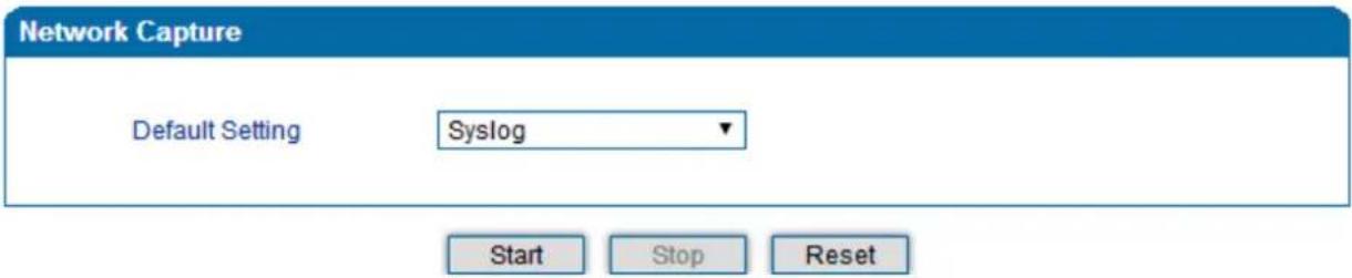
- Click "Start" to enable syslog capture
♦ Dialing out through gateway, start talking a short while and then hanging up the call. - Click 'Stop' to disable syslog capture
- Save the capture to local computer
The capture is named as 'capture(x).pcap'; x is serial number of capture and will be added 1 next time.
The sample of syslog capture is shown below:
| No. | Time | Source | Destination | Protocol | Length | Info |
| 1 | 0.000000 | 172.16.222.22 | 1.1.1.1 | syslog | 172 | USER_DEBUG: Jul 23 06:52:05 172.16.222.22 mpe_sip: < 0> [DEBUG] ---> to 172.16.222.22/5060 crypt:FALSE Phone |
| 2 | 0.000344 | 172.16.222.22 | 1.1.1.1 | syslog | 520 | USER_DEBUG: Jul 23 06:52:05 172.16.222.22 mpe_sip: < 1> [DEBUG] OPTIONS slip:heartbeat8172.16.222.22 SIP/2.0\n^ |
| 3 | 0.013432 | 172.16.222.22 | 1.1.1.1 | syslog | 595 | USER_DEBUG: Jul 23 06:52:05 172.16.222.22 mpe_sip: < 2> [DEBUG] <----*** message from 172.16.222.22/5060.crypt |
| 4 | 0.013750 | 172.16.222.22 | 1.1.1.1 | syslog | 176 | USER_DEBUG: Jul 23 06:52:05 172.16.222.22 mpe_sip: < 3> [DEBUG] <---- from 172.16.222.22/5060.crypt:FALSE, Pho |
| 5 | 0.014036 | 172.16.222.22 | 1.1.1.1 | syslog | 520 | USER_DEBUG: Jul 23 06:52:05 172.16.222.22 mpe_sip: < 4> [DEBUG] OPTIONS slip:heartbeat8172.16.222.22 SIP/2.0\n^ |
| 6 | 0.014512 | 172.16.222.22 | 1.1.1.1 | Syslog | 172 | USER_DEBUG: Jul 23 06:52:05 172.16.222.22 mpe_sip: < 5> [DEBUG] ---> to 172.16.222.22/5060 crypt:FALSE Phone |
| 7 | 0.014806 | 172.16.222.22 | 1.1.1.1 | Syslog | 587 | USER_DEBUG: Jul 23 06:52:05 172.16.222.22 mpe_sip: < 6> [DEBUG] SIP/2.0 200 OK\r\nvia: SIP/2.0/UDP 172.16.222. |
| 8 | 0.028396 | 172.16.222.22 | 1.1.1.1 | Syslog | 662 | USER_DEBUG: Jul 23 06:52:05 172.16.222.22 mpe_sip: < 7> [DEBUG] <----*** message from 172.16.222.22/5060.crypt |
| 9 | 0.028759 | 172.16.222.22 | 1.1.1.1 | Syslog | 176 | USER_DEBUG: Jul 23 06:52:05 172.16.222.22 mpe_sip: < 8> [DEBUG] <---- from 172.16.222.22/5060.crypt:FALSE, Pho |
| 10 | 0.029052 | 172.16.222.22 | 1.1.1.1 | Syslog | 587 | USER_DEBUG: Jul 23 06:52:05 172.16.222.22 mpe_sip: < 9> [DEBUG] SIP/2.0 200 OK\r\nvia: SIP/2.0/UDP 172.16.222. |
| 11 | 0.030017 | 172.16.222.22 | 1.1.1.1 | Syslog | 233 | USER_DEBUG: Jul 23 06:52:05 172.16.222.22 mpe_sip: < 10> [DEBUG] sip->app: msgtype:ST_SIP_SERVER_CONN\r\n cal |
| 12 | 0.331167 | 172.16.222.22 | 1.1.1.1 | Syslog | 983 | USER_DEBUG: Jul 23 06:52:05 172.16.222.22 mpe_sip: < 11> [DEBUG] <----* message from 172.16.222.127/5060.crypt |
| 13 | 0.331498 | 172.16.222.22 | 1.1.1.1 | Syslog | 177 | USER_DEBUG: Jul 23 06:52:05 172.16.222.22 mpe_sip: < 12> [DEBUG] <---- from 172.16.222.127/5060.crypt:FALSE, Pf |
| 14 | 0.331959 | 172.16.222.22 | 1.1.1.1 | Syslog | 907 | USER_DEBUG: Jul 23 06:52:05 172.16.222.22 mpe_sip: < 13> [DEBUG] INWITE sip:1008600/7.26.222.22:5060 SIP/2.0\n^ |
| 15 | 0.332307 | 172.16.222.22 | 1.1.1.1 | Syslog | 122 | USER_DEBUG: Jul 23 06:52:05 172.16.222.22 mpe_ecc: < 14> [DEBUG] get route entry 31\r\n |
| 16 | 0.332384 | 172.16.222.22 | 1.1.1.1 | Syslog | 111 | USER_DEBUG: Jul 23 06:52:05 172.16.222.22 mpe_ecc: < 15> [DEBUG] Port:3\r\n |
| 17 | 0.332848 | 172.16.222.22 | 1.1.1.1 | Syslog | 124 | USER_DEBUG: Jul 23 06:52:05 172.16.222.22 mpe_ecc: < 16> [DEBUG] get route, to port:3\r\n |
| 18 | 0.333315 | 172.16.222.22 | 1.1.1.1 | Syslog | 526 | USER_DEBUG: Jul 23 06:52:05 172.16.222.22 mpe_sip: < 17> [DEBUG] sip->app: localindex:69, msgtype:SIP_CALL_INA |
| 19 | 0.333603 | 172.16.222.22 | 1.1.1.1 | Syslog | 173 | USER_DEBUG: Jul 23 06:52:05 172.16.222.22 mpe_sip: < 18> [DEBUG] ---> to 172.16.222.127/5060 crypt:FALSE, Pho# |
| 20 | 0.333877 | 172.16.222.22 | 1.1.1.1 | Syslog | 386 | USER_DEBUG: Jul 23 06:52:05 172.16.222.22 mpe_sip: < 19> [DEBUG] SIP/2.0 100 trying\r\nvia: SIP/2.0/UDP 172.16. |
| 21 | 0.346687 | 172.16.222.22 | 1.1.1.1 | Syslog | 131 | USER_DEBUG: Jul 23 06:52:05 172.16.222.22 mpe_ecc: < 20> [DEBUG] RTP: alg:0, pkt:70, band:-1\r\n |
| 22 | 0.347453 | 172.16.222.22 | 1.1.1.1 | Syslog | 120 | USER_DEBUG: Jul 23 06:52:05 172.16.222.22 mpe_ecc: < 21> [DEBUG] dial tick:102433\r\n |
| 23 | 7.232839 | 172.16.222.22 | 1.1.1.1 | Syslog | 533 | USER_DEBUG: Jul 23 06:52:12 172.16.222.22 mpe_sip: < 22> [DEBUG] <----*** message from 172.16.222.127/5060,crypt |
| 24 | 7.233513 | 172.16.222.22 | 1.1.1.1 | Syslog | 177 | USER_DEBUG: Jul 23 06:52:12 172.16.222.22 mpe_sip: < 23> [DEBUG] <---- from 172.16.222.127/5060.crypt:FALSE, Pf |
| 25 | 7.233959 | 172.16.222.22 | 1.1.1.1 | Syslog | 457 | USER_DEBUG: Jul 23 06:52:12 172.16.222.22 mpe_sip: < 24> [DEBUG] CANCEL SIP:1008600/7.26.222.22:5060 SIP/2.0\n^ |
| 26 | 7.234596 | 172.16.222.22 | 1.1.1.1 | Syslog | 287 | USER_DEBUG: Jul 23 06:52:12 172.16.222.22 mpe_sip: < 25> [DEBUG] sip->app: localindex:69, msgtype:SIP_CALL_BY |
▶ Getting started to RTP capture
PCM capture helps to analyze voice stream between gateway and remote IPPBX/SIP Server.
▶ To enable RTP capture:
- Select RTP special on Network Capture page
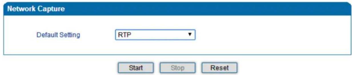
- Click Start to enable RTP capture
- Dial out through gateway, start talking for a short time and then hang up the call.
- Click Stop to disable RTP capture
- Save the capture to local computer
The capture is named as 'capture(x).pcap'; x is serial number of capture and will be added 1 next time.
The sample of RTP capture is shown below:
| No. | Time | Source | Destination | Protocol | Length | Info |
| 176 | 7.020000 | 172.16.221.228 | 116.204.105.50 | SIP | 565 | Request: REGISTER sip:116.204.105.50 | |
| 178 | 7.030000 | 116.204.105.50 | 172.16.221.228 | SIP | 411 | Status: 200 OK (1 bindings) | |
| 244 | 11.610000 | 172.16.221.228 | 58.56.64.101 | SIP/SDP | 814 | Request: INVITE sip:201058.56.64.101 | |
| 248 | 11.710000 | 58.56.64.101 | 172.16.221.228 | SIP | 480 | Status: 100 Trying | |
| 249 | 11.710000 | 58.56.64.101 | 172.16.221.228 | SIP/SDP | 733 | Status: 183 Session Progress | |
| 250 | 11.710000 | 58.56.64.101 | 172.16.221.228 | SIP/SDP | 719 | Status: 200 OK | |
| 252 | 11.720000 | 172.16.221.228 | 58.56.64.101 | RTP | 66 | Unknown RTP version 1 |
| 253 | 11.720000 | 172.16.221.228 | 58.56.64.101 | RTP | 66 | Unknown RTP version 1 |
| 254 | 11.720000 | 58.56.64.101 | 172.16.221.228 | RTP | 74 | PT-ITU-T G.729, SSRC-Ox497E6D15, Seq=1000, Time=160, Mark |
| 255 | 11.720000 | 172.16.221.228 | 58.56.64.101 | RTP | 66 | Unknown RTP version 1 |
| 256 | 11.730000 | 172.16.221.228 | 58.56.64.101 | RTP | 66 | Unknown RTP version 1 |
| 257 | 11.730000 | 172.16.221.228 | 58.56.64.101 | RTP | 66 | Unknown RTP version 1 |
| 258 | 11.740000 | 172.16.221.228 | 58.56.64.101 | SIP | 434 | Request: ACK sip:201058.56.64.101:5060 | |
| 259 | 11.740000 | 58.56.64.101 | 172.16.221.228 | RTP | 74 | PT-ITU-T G.729, SSRC=0x497E6D15, Seq=1001, Time=320 |
| 261 | 11.770000 | 58.56.64.101 | 172.16.221.228 | RTP | 74 | PT-ITU-T G.729, SSRC-Ox497E6D15, Seq=1002, Time=480 |
| 263 | 11.780000 | 58.56.64.101 | 172.16.221.228 | RTP | 74 | PT-ITU-T G.729, SSRC=0x497E6D15, Seq=1003, Time=640 |
| 264 | 11.810000 | 58.56.64.101 | 172.16.221.228 | RTP | 74 | PT-ITU-T G.729, SSRC=0x497E6D15, Seq=1004, Time=800 |
| 265 | 11.830000 | 58.56.64.101 | 172.16.221.228 | RTP | 74 | PT-ITU-T G.729, SSRC=0x497E6D15, Seq=1005, Time=960 |
| 266 | 11.840000 | 58.56.64.101 | 172.16.221.228 | RTP | 74 | PT-ITU-T G.729, SSRC=0x497E6D15, Seq=1006, Time=1120 |
| 267 | 11.870000 | 58.56.64.101 | 172.16.221.228 | RTP | 74 | PT-ITU-T G.729, SSRC=0x497E6D15, Seq=1007, Time=1280 |
| 268 | 11.890000 | 58.56.64.101 | 172.16.221.228 | RTP | 74 | PT-ITU-T G.729, SSRC=0x497E6D15, Seq=1008, Time=1440 |
| 270 | 11.900000 | 58.56.64.101 | 172.16.221.228 | RTP | 74 | PT-ITU-T G.729, SSRC=0x497E6D15, Seq=1009, Time=1600 |
| 271 | 11.930000 | 172.16.221.228 | 58.56.64.101 | RTP | 74 | PT-ITU-T G.729, SSRC=0x43455AA6, Seq=31521, Time=1806312883 |
| 273 | 11.930000 | 58.56.64.101 | 172.16.221.228 | RTP | 74 | PT-ITU-T G.729, SSRC=0x497E6D15, Seq=1010, Time=1760 |
| 274 | 11.940000 | 58.56.64.101 | 172.16.221.228 | RTP | 74 | PT-ITU-T G.729, SSRC=0x497E6D15, Seq=1011, Time=1920 |
| 275 | 11.950000 | 172.16.221.228 | 58.56.64.101 | RTP | 74 | PT-ITU-T G.729, SSRC=0x43455AA6, Seq=31522, Time=1806313043 |
| 277 | 11.970000 | 58.56.64.101 | 172.16.221.228 | RTP | 74 | PT-ITU-T G.729, SSRC=0x497E6D15, Seq=1012, Time=2080 |
| 278 | 11.970000 | 172.16.221.228 | 58.56.64.101 | RTP | 74 | PT-ITU-T G.729, SSRC=0x43455AA6, seq=31523, Time=1806313203 |
▶ Getting started with DSP capture
DSP capture helps to analyze voice stream inside the DSP chipset. The DSP chipset handles RTP from IP network as well as voice stream from analog phone.
▶ To enable DSP capture:
- Select DSP only on Network Capture page
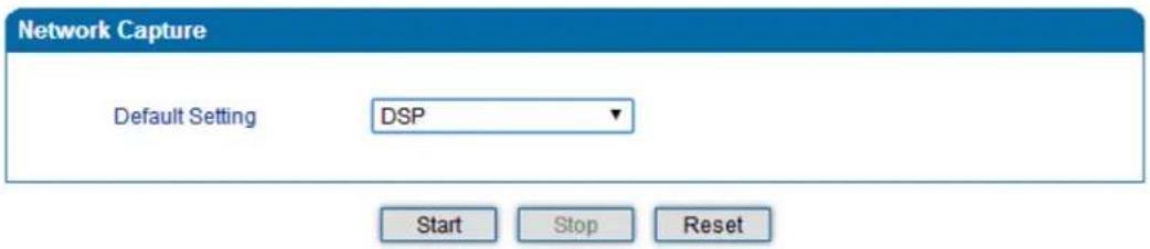
- Click Start to enable DSP capture
◆ Dial out through gateway, start talking a short time and then hang up the call. - Click Stop to disable DSP capture
- Save the capture to local computer
The capture is named as 'capture(x).pcap'; x is serial number of capture and will be added 1 next time. The sample of RTP capture is shown below:
| No. | Time | Source | Destination | Protocol | Length Info | |
| 1 | 0.000000 | Motorola_1c:1d:1e | Cimsys_33:44:55 | CSM_ENCAPS | 104 --> 0x0021 | Ch: 0xFFFF, Seq: 2 (From Host) |
| 2 | 0.007246 | Cimsys_33:44:55 | Motorola_1c:1d:1e | Ethernet | 20 Ethernet II[Malformed Packet] | |
| 3 | 0.007260 | Cimsys_33:44:55 | Motorola_1c:1d:1e | CSM_ENCAPS | 44 --> 0x0021 | Ch: 0xFFFF, Seq: 5 (From Host) |
| 4 | 2.994581 | Motorola_1c:1d:1e | Cimsys_33:44:55 | CSM_ENCAPS | 104 --> 0x0021 | Ch: 0xFFFF, Seq: 3 (From Host) |
| 5 | 2.997308 | Cimsys_33:44:55 | Motorola_1c:1d:1e | Ethernet | 20 Ethernet II[Malformed Packet] | |
| 6 | 2.997316 | Cimsys_33:44:55 | Motorola_1c:1d:1e | CSM_ENCAPS | 44 --> 0x0021 | Ch: 0xFFFF, Seq: 6 (From Host) |
| 7 | 5.992790 | Motorola_1c:1d:1e | Cimsys_33:44:55 | CSM_ENCAPS | 104 --> 0x0021 | Ch: 0xFFFF, Seq: 4 (From Host) |
| 8 | 5.997282 | Cimsys_33:44:55 | Motorola_1c:1d:1e | Ethernet | 20 Ethernet II[Malformed Packet] | |
| 9 | 5.997290 | Cimsys_33:44:55 | Motorola_1c:1d:1e | CSM_ENCAPS | 44 --> 0x0021 | Ch: 0xFFFF, Seq: 7 (From Host) |
| 10 | 7.691428 | Motorola_1c:1d:1e | Cimsys_33:44:55 | CSM_ENCAPS | 104 --> 0x9010 | Ch: 0x0003, Seq: 3 (From Host) |
| 11 | 7.691552 | Cimsys_33:44:55 | Motorola_1c:1d:1e | Ethernet | 20 Ethernet II[Malformed Packet] | |
| 12 | 7.691715 | Cimsys_33:44:55 | Motorola_1c:1d:1e | CSM_ENCAPS | 30 <-- 0x9010 | Ch: 0x0003, Seq: 1 (To Host) |
| 13 | 7.701379 | Motorola_1c:1d:1e | Cimsys_33:44:55 | CSM_ENCAPS | 104 --> 0x9000 | Ch: 0x0003, Seq: 4 (From Host) |
| 14 | 7.701494 | Cimsys_33:44:55 | Motorola_1c:1d:1e | Ethernet | 20 Ethernet II[Malformed Packet] | |
| 15 | 7.701622 | Cimsys_33:44:55 | Motorola_1c:1d:1e | CSM_ENCAPS | 30 <-- 0x9000 | Ch: 0x0003, Seq: 2 (To Host) |
| 16 | 7.709662 | Motorola_1c:1d:1e | Cimsys_33:44:55 | CSM_ENCAPS | 104 --> 0x8084 | Ch: 0x0003, Seq: 5 (From Host) |
| 17 | 7.709798 | Cimsys_33:44:55 | Motorola_1c:1d:1e | Ethernet | 20 Ethernet II[Malformed Packet] | |
| 18 | 7.709902 | Cimsys_33:44:55 | Motorola_1c:1d:1e | CSM_ENCAPS | 30 <-- 0x8084 | Ch: 0x0003, Seq: 3 (To Host) |
| 19 | 7.710238 | Motorola_1c:1d:1e | Cimsys_33:44:55 | CSM_ENCAPS | 104 --> 0x8001 | Ch: 0x0003, Seq: 6 (From Host) |
| 20 | 7.710328 | Cimsys_33:44:55 | Motorola_1c:1d:1e | Ethernet | 20 Ethernet II[Malformed Packet] | |
| 21 | 7.710496 | Cimsys_33:44:55 | Motorola_1c:1d:1e | CSM_ENCAPS | 30 <-- 0x8001 | Ch: 0x0003, Seq: 4 (To Host) |
| 22 | 7.716241 | Motorola_1c:1d:1e | Cimsys_33:44:55 | CSM_ENCAPS | 104 --> 0x8018 | Ch: 0x0003, Seq: 7 (From Host) |
| 23 | 7.716352 | Cimsys_33:44:55 | Motorola_1c:1d:1e | Ethernet | 20 Ethernet II[Malformed Packet] | |
| 24 | 7.716465 | Cimsys_33:44:55 | Motorola_1c:1d:1e | CSM_ENCAPS | 30 <-- 0x8018 | Ch: 0x0003, Seq: 5 (To Host) |
| 25 | 7.716711 | Motorola_1c:1d:1e | Cimsys_33:44:55 | CSM_ENCAPS | 104 --> 0x805b | Ch: 0x0003, Seq: 8 (From Host) |
▶ Configurable capture options
▶ Getting started with custom capture
This menu provides more options to capture specific packets according to actual needs.
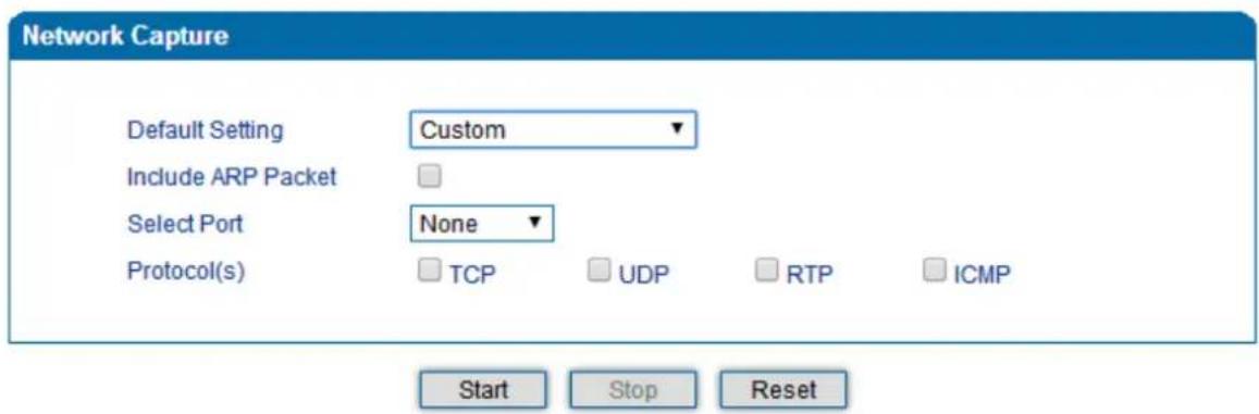
3.14.8 Factory Reset
Click 'Apply' to restore the factory settings.
Factory Reset
Click the button below to reset to factory default settings.
Apply
Factory Reset
3.14.9 Device Restart
After saving all the configurations or changes to the equipment, user can restart the VGW-X20FS SERIES gateway for the changes to take effect.
Restart
Click the button below to restart the device.
Restart
Restart Gateway


- User's Manual
- Copyright
- Disclaimer
- CE Mark Warning
- Energy Saving Note of the Device
- WEEE Warning
- Trademarks
- Revision
- Preface
- Welcome
- About this manual
- Intended audience
- Contents
- Preface 4
- Introduction of VGW-X20FS SERIES 8
- Basic Operations 18
- Configurations on Web Interface 24
- Introduction of VGW-X20FS SERIES
- Overview
- High Quality yet Affordable for All Businesses
- Enhanced, Full-Featured Business Gateway
- Distributed VoIP Network Infrastructure
- Product Features
- ▶ SIP Applications
- Internet Features
- ▶ Call Features
- Ports and Connectors
- VGW-420FS
- VGW-820FS
- VGW-1620FS
- VGW-2420FS
- VGW-2420FS Front Panel
- VGW-2420FS Rear Panel
- VGW-3220FS
- Basic Operations
- Methods of Number Dialing
- Direct IP Calls
- Example:
- Call Holding
- Call Waiting
- Call Transfer
- Blind Transfer
- Note :
- Attended Transfer
- Three-way Calling
- Three-way calling
- Description of Feature Codes
- Sending and Receiving Fax
- T. 38 and Pass-through
- Local IVR Operation
- Inquire IP address
- Factory Reset
- Configure LAN Port's IP Address
- Configure dynamic IP address by DHCP:
- Configure Static IP address:
- Configurations on Web Interface
- Logging in Web Interface
- Navigation Tree
- State and Statistics
- System Information
- Registration Information
- TCP/UDP Statistics
- RTP Session Statistics
- CDR Statistics
- Quick Setup Wizard
- Network Configuration
- Local Network
- DHCP:
- Static IP Address:
- PPPoE:
- Local Network
- Network Mode
- WAN Port
- LAN Port
- DNS Server
- VLAN (Virtual Local Area Network)
- ▶ 802.1Q
- ▶ 802.1P
- DHCP Server (Route Mode for VGW-420FS/820FS)
- DMZ Host (Route Mode for VGW-420FS/820FS)
- Forward Rule (Route Mode for VGW-420FS/820FS)
- Static Route (Route Mode for VGW-420FS/820FS)
- ARP
- SIP Server
- Introduction of SIP Server:
- SIP Server
- Primary SIP Server
- Secondary SIP Server
- Primary Outbound Proxy
- Secondary Outbound Proxy
- Registration
- SIP Transport Type
- Local SIP Port
- Port
- Port Modify
- Advanced
- FXS/FXO Parameters
- FXS / FXO
- Line Parameter
- FXS Parameter
- Media Parameter
- SIP Parameters
- SIP Parameter
- Voicemail instructions:
- Voicemail
- Fax Parameter
- Digit Map
- Digit Map Syntax
- Examples:
- Feature Codes
- System Parameter
- Action URL
- Call & Routing
- Wildcard Group
- Port Group
- IP Trunk
- Routing Parameter
- IP -> Tel Routing
- Tel-IP/Tel Routing
- IP - IP Routing
- Manipulation Configuration
- IP -> Tel Callee
- Tel -> IP/Tel Caller
- Tel-IP/Tel Callee
- Routing rule examples
- Route any calls from any IP to specific port
- NOTES:
- Route any calls from any IP to specified port group
- Route any calls from any port to specific SIP IP trunk
- Maintenance
- TR069
- SNMP (Simple Network Management Protocol)
- SNMP Parameters:
- SNMP Parameter
- SNMP Version
- Group configuration
- Trap configuration
- Syslog
- Provision
- Cloud Server
- Security
- WEB ACL
- ACL
- Telnet ACL
- ACL for Telnet
- Passwords
- Password Modification
- Tools
- Firmware upload
- Step 4.
- Prompt
- Step 5.
- Restart
- Data Backup
- Data Restore
- Ping Test
- Tracert Test
- Tracert introduce :
- Outward Test
- Test results
- Network Capture
- Default Setting is PCM capture
- ▶ Getting started to Syslog capture
- ▶ To enable syslog capture
- ▶ Getting started to RTP capture
- ▶ To enable RTP capture:
- ▶ Getting started with DSP capture
- ▶ To enable DSP capture:
- ▶ Configurable capture options
- ▶ Getting started with custom capture
- Factory Reset
- Factory Reset
- Device Restart
Brand : Planet
Model : VGW-2420FS
Category : Uncategorized