
HS (2019) - Automotive MG - Free user manual and instructions
Find the device manual for free HS (2019) MG in PDF.


User questions about HS (2019) MG
0 question about this device. Answer the ones you know or ask your own.
Ask a new question about this device
Download the instructions for your Automotive in PDF format for free! Find your manual HS (2019) - MG and take your electronic device back in hand. On this page are published all the documents necessary for the use of your device. HS (2019) by MG.
USER MANUAL HS (2019) MG
VehicleIdentificationInformation....3
Vehicle identification....3
VehicleIdentificationLabel 4
I InstrumentsandControls....5
InstrumentsandControls....6
InstrumenPack....8
MessageCentre....9
Warning Lights and Indicators....21
LightandSwitches....34
MastelLighSwitch....34
Headlamp Levelling Adjustment 36
Lighting eve switch....37
CONTENTS
SmarMairBeanSystem....38
FogamSwitch....40
Hazard Warningamps....40
WipersandWashers....41
FrontWindscreenWipeControls....41
RealWindscreenWiperControls....43
SteeringSystem....45
Adjustment Steering Column....45
ElectricPowerSteering....46
Horn....47
RearviewMirrors....48
ExteriorDoorMirrors....48
Automatic Anti-dazzlnterioRearviewMirror....50
Sunvisor....52
Windows....53
PowerOperatedWindowSwitch....53
WindowOperation....53
Sunroof....56
CONTENTS
Instructions....56
SunrooOperation....56
InteriorLight....62
FrontInteriorLamp....62
RearInteriorLamp ^* 63
AmbientLamps ^* 63
PowerSocket....64
StorageDevices....66
Instructions....66
GloBox....66
StorageBoxDriveSide....67
CentreConsoleArmresBox....67
LoaSpaceCompartment....68
CupHolder....69
CentreConsole Cup Holder....69
RearArmrestandRearCupHolder....69
RoofLuggageRack * 70
MaximumAuthorisedLoadorthRoof....70
PeriodicaCheck....70
CONTENTS
2AirConditioningandAudioSystems....71
Ventilation....72
A/Particle/PollerFilter....73
Vents....73
ElectronicT emperatureControl 75
InfotainmenScreenControlInterface....75
ControPanel....78
A/©display....79
AutomaticT emperatureControl 80
InfotainmenScreenControlInterface....80
ControPanel....83
A/Status....85
InfotainmentSystem....86
Important Safety Information....86
Cautionsoi Using screen....87
AdditionaNotes....88
Basic Operations....88
Bluetooth|Phone....94
Entertainment....102
CONTENTS
Vehicle-MobilePhoneInterconnection * 110
A/C......III
VehicleSettings....III
Settings....112
3Seats&Restraints....115
Seats......116
Overview....116
HeadRestraint....116
Fron6eats....117
ReaSeats....119
FrontSeatHeating 120
SeaBelts....122
Protection Provided by Sea Belts....123
WearingSeaBelts....124
Children and Sea Belts....129
SeaBelPre-tensioners....130
SeaBelChecksMaintenanceandReplacement....131
AirbagSupplementaryRestraintSystem....133
Overview....133
CONTENTS
AirbagDeployment....134
ConditionsWhichAirbagsWillNoDeploy....137
Disablingthe PassengerAirbag....138
ServicandReplacementAirbags....140
DisposabAirbags....141
ChildRestraints....142
Important Safety Instructions about Using Child Restraints....142
ChildRestraintsGroups....145
ApprovedChildRestrainPositions....147
Starting & Driving....153
Keys....154
Overview....154
ReplacingBattery....155
ChildProoLocks....158
AlarmSystems....159
Enginemmobiliser....159
Vehicle Anti-thefSystem....160
ManualT ailgate ^* 164
CONTENTS
Electric T ailgate ^* 165
TailgateEmergencyOpen....168
Starting and Stopping Engine....169
START/STORSwitch....169
StartinghEngine....170
StoppingEngine....172
EconomicalandEnvironmentalDriving....173
Running-in....173
EnvironmentProtection....173
Economic Driving and Maintenance....173
DrivingSpecialEnvironment....175
CatalyticConverterandParticulateFilter....176
FueSystem....178
FueRequirements....178
FueFiller....179
Refueling....179
ManualT transmission ^* ....181
DualClutchAutomaticT transmission\*....183
Instructions....183
CONTENTS
ElectroniShifLever....183
ManualMode * 186
ProtectionMode....187
DrivingMode * 189
BrakeSystem....192
FooBrake....192
HilDescenContro(HDC)....197
Anti-lockBrakeSystem(ABS)....199
ActiveRolloverProtection(ARP)....200
Emergency Braking Hazard Warning Lights Control System(HAZ)....201
Electronic Parking Brake(EPB)....202
StabilityControlSystem(SCS)andT ractionControlSystem(TCS)....204
T yrePressureMonitoringSystem(TPMS)....206
STOP-STARTIntelligentFuelSavingSystem....207
AutomaticShutdownEngine....208
AutomatiEnginStart....209
Battery....210
Stop-StartIntelligenFueSavingSystemFailure....211
StartelmoperativeSeriousBatteryCapacityLoss....211
CONTENTS
CruiseControlSystem \* 212
CruiseControlSystemActivation....212
TargeCruiseSpeedAdjustment....213
Pause/StandBy....213
Resume....214
AdaptiveCruiseControlSystem \* 215
Adaptive Cruise Control System Activation....216
Adaptive Cruise Target Speed Adjustment....219
Adaptive Cruise Target Following Distance Adjustment....220
Adaptive Cruise Pause....220
AutomaticDeactivationAdaptiveCruise....220
Adaptive Cruise Override....221
Adaptive Cruise Resume....221
CleartheSpeedMemory....221
SpeciaDrivingEnvironments....222
ParkingAidSystem \* 225
UltrasonicSensorParkingAid * 225
ParkingCamera ^* 226
RealDriverAssistanceSystem....227
CONTENTS
SystemOverview....227
SwitchinghSystemFunctionOn/Off....228
SystemFunctions....229
DrivingAssisSystem....235
DescriptionoFrontViewCamera....235
Description From Detection Radar....236
SpeedAssisSystem(SAS)....238
LaneDepartureWarningSystem(LDW)....243
LaneDeparturePreventionSystem(LDP)....247
Land Keeping Assis System(LKA)....251
MGPilotSystem * 255
ForwardCollisionWarningSystem(FCW)....259
AutomaticEmergencyBrakingSystem(AEB)andAutomaticEmergencyBrakingSystemforPedestrians (AEBP)....261
LoadCarrying....266
Loadspace....266
InternalLoading....267
GeneraT owing safety....267
5EmergencyInformation....269
CONTENTS
HazardWarning Devices....270
Hazard Warningamps....270
Warning Triangle....270
eCalISOEmergencyAssistance....272
EmergencyStarting....274
Using Booster Cables....274
Startinghe/ehicle....274
VehicleRecovery....276
Towing for Recovery....276
Transporter....279
TyreRepair....280
Toolidentification(includingyrerepaitool)....280
TyrRepair....280
ChangingaWheel * 283
FuseReplacement....287
Fuse....287
FusBox....287
BullReplacement....294
CONTENTS
BullSpecification....294
BuiltReplacement....294
6Maintenance....301
Maintenance....302
RoutinServicing....302
Bonnet....306
OpeninghBonnet....306
ClosinghBonnet....306
BonneOpenAlarm....306
EngineCompartment....308
Engine....309
1.5LT urbochargedEngineOil....309
EngineOileveCheckandTopUp....309
EngineOispecification....310
CoolingSystem....311
CoolantCheckandTopUp....311
CoolanSpecification....311
Brake....313
CONTENTS
BrakePads....313
BrakeFluidCheckandTopUp....313
BrakeFluiSpecification....314
Battery....315
Battery Maintenance....315
Battery Replacement....315
Washer....317
WashFluidCheclandTopUp....317
Washer Nozzles....318
Wipers....319
WipeBlades....319
ReplacingFrontWindscreenWiperBlades....320
ReplacingRearWindowWipeBlades....321
Tyres....322
Overview....322
TyrCheck....324
TyreW earIndicators....324
Replacementoff yres....325
WheeFitmenRotation....325
CONTENTS
Tyre/SnowChains....326
CleaningandVehicleCare....328
ExternaCare....328
Cleaningdnterior....331
echnicaData....333
TechnicaDataDimensions....334
Weights....336
Towing/Weights....337
Towing Ba Dimensions....338
MajorParametersEngine....340
RecommendedFluidsandCapacities....341
Four-WheelAlignmentParameterT able(Unladen)....342
WheelsandT yres....342
TyrePressure(Cold)....342
8Appendix....343
RemovableTowBar....344
TovBarOperatingInstructions....344
Introduction
TheOwner'sHandbook
This handbook describes all of the vehicles and standard equipments specification within the model range. Some of the information therefore, may not apply to your particular car.
Alwaysrememberthatifyouhaveanyqueriesconcerning theoperationorspecificationofyourcar,yourMG AuthorisedRepairerwillbegladtoadviseyou.
StatusatTimeofPrinting
MGoperatesapolicyofconstantproductimprovement andthereforereservestherighttochangespecifications withoutnoticeatanytime.Whilsteveryeffortis madetoensurecompleteaccuracyoftheinformation inthispublication,noliabilitiesforinaccuraciesorthe consequencesthereof,includinglossordamageto property,orinjurytopersons,canbeacceptedbythe manufacturerorMGAuthorisedRepairerwhosupplied thepublication,exceptinrespectofpersonalinjurycaused bythenegligenceofthemanufacturerorMGAuthorised Repairer.
SymbolsUsed
The following symbols used within the handbook can your attention to specific types of information.
Warning

This warningsymbolidentifies procedures that must be followed precisely, information that must be considered with great care, in order to reduce the risk of personal injury or serious damage to the car.
Important
IMPORTANT
Thestatementsstatedheremustbefollowedstrictly, otherwiseyourcarcouldbedamaged.
Note
Note: This describes helpful information.
PREFACE

Thissymbolindicatespartsdescribedmustbe disposedofbyauthorisedpersonsorbodiestoprotect theenvironment.
Asterisk
Anasterisk(*)appearingwithinthetext,identifiesfeatures oritemsofequipmentthatareeitheroptional,orareonly fittedtosomevehiclesinthemodelrange.
IllustrationInformation

Identifiescomponentsbeingexplained.

Identifies movement of components being explained.
InanEmergency
IMPORTANT
Rememberthebreakdownsafetycode
Ifabreakdownoccurswhiletravelling:
- Whereverpossible,consistentwithroadsafetyand trafficconditions,thecarshouldbemovedoffthe mainthoroughfare,preferablyintoalay-by.lfa breakdownoccursonamotorway,pullwelloverto theinsideofthehardshoulder.
- Switchonhazardlights.
•Ifavailable,positionawarningtriangleoraflashing amberlight150to500ftbehindyourvehicletowarn approachingtraffic.Noteitisalegalrequirement ofsomecountriesthatawarningtriangleiscarried inthevehicle,ifindoubtconsultthelocalhighways agencyforfurtherinformation.
- Considerevacuatingpassengersthroughnearside doorsontothevergeasaprecautionincaseyour vehicleisaccidentallystruckbyothertraffic.
VehicleIdentificationInformation
VehicleIdentification
text_image
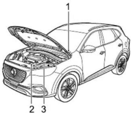
Technical diagram of a car with labeled parts, showing engine compartment and structural componentsI VehicleIdentificationNumber(VIN)
2EngineNumber
3T transmissionNumber
AlwaysquotetheVehicleIdentificationNumber(VIN) whencommunicatingwithyourMGAuthorisedRepairer .
If the engine or transmission is involved, it may be required to provide the identification numbers of these assemblies.
VehicleIdentificationLocation
VINLocation
•Onthefloorunderthefrontdriverseat;
- Stampedonaplatevisiblethroughthebottomlefthand cornerofthewindscreen;
•Ontheidentificationplate;
- Ontheinnersideofthetailgatevisiblebyopeningthe tailgate.
Note: The DLC of the vehicle is located on the upper left of the brake pedal. The VIN information can be extracted from the vehicle using the approved diagnostic equipment.
EngineNumberLocation
Stampedonthefrontrightofthecylinderblock(Viewfrom thefrontoftheengine).
TransmissionNumberLocation
PREFACE
Onthesurfaceofthetransmissionhousingintheengine compartment. Thetransmissionnumbersofcertain modelsareonlyvisiblebyraisingthevehicle,please contactalocalAuthorisedRepairer.
VehicleIdentificationLabel
The vehicle identification label contains the following information:
- Model/T ype;
-EngineT ype;
•VehicleIdentificationNumber(VIN); - Date;
•GrossVehicleWeight;
•GrossT rainWeight *;
•MaxFrontAxleWeight *;
•MaxRearAxleWeight *;
•Country;
•Manufacturer.
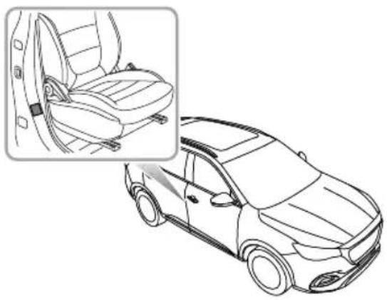
LocationofV ehicleIdentificationLabel
Theidentificationlabelislocatedatthelowersideofright pillarB
natural_image
Line drawing of a car interior showing seatbelt and seatbelt seat, with no text or symbols present.InstrumentsandControls
6InstrumentsandControls
8 InstrumentPack
9MessageCentre
2 | WarningLightsandIndicators
34LightsandSwitches
41 WipersandWashers
45SteeringSystem
47Horn
48 RearviewMirrors
52Sunvisor
53Windows
56Sunroof*
62 InteriorLight
64 PowerSocket
66 StorageDevices
69CupHolder
70RoofLuggageRack
INSTRUMENTSANDCONTROLS
InstrumentsandControls

text_image
12 11 10 98 7 6 5 4 3 2 1 13 14 15 16 17 18 19 20INSTRUMENTSANDCONTROLS
I ExteriorRearviewMirrorsandPowerWindowSwitch
2Wiper/WasherControl
3START/STOPSwitch
4GearPaddle+ *
5HornButton
6DriverAirbag
7InstrumentPack
8GearPaddle- *
9IndicatorandMainBeamStalkSwitch
10OnboardEntertainmentSystem
I | Entertainment/AirConditioningControls
12FrontPassengerAirbag
I3GearShiftLever
14ClutchPedal *
15CruiseStalkSwitch
16BrakePedal
17AcceleratorPedal
18SuperSportButton
19BonnetReleaseHandle
20HeadlampLevellingAdjustmentSwitch
INSTRUMENTSANDCONTROLS
InstrumentPack
text_image
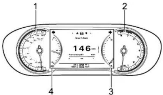
1 2 146- Time Measurement 3 4 3Speedometer(1)
Indicates the vehicle speed in km/h.
Tachometer(2)
Indicate the engine speed, 1000 pm.
IMPORTANT
T protecthengin frondamage ever allow the pointe remain the eedecto th gaug for prolonge periods.
EngineCoolant TemperatureGauge(3)
Indicate the engine coolant temperature.
FueGauge(4)
Indicates the quantity of fuel in the tank.
Theovue warningampvilluminaty yellowoflash whertheueremainingthefuetanklow.
IMPORTANT
Ithedowfuewarningampilluminatespleaserefuehs earlypossible.

Tharrow the following fuel warningamp
indicates that fue fille is located both defside the vehicle.
INSTRUMENTSANDCONTROLS
MessageCentre
text_image
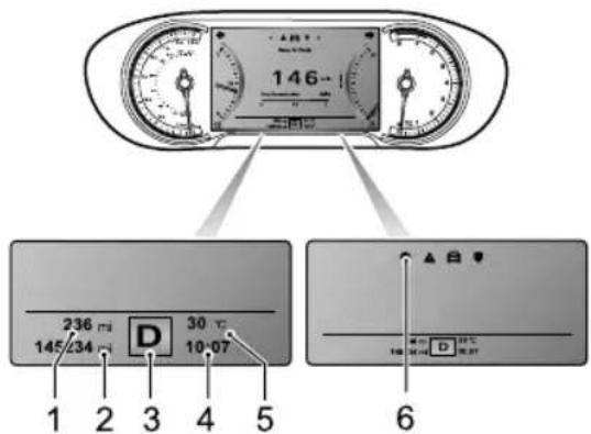
146 236 mi 145/234 mi D 30 °C 10-07 1 2 3 4 5 6Themessagecentreprovidesthefollowings:
IAccumulativeT ripMeter
2Odometer
3GearDisplay/GearShiftIndication/PowerSystem ModeDisplay *
4DigitalClock
5ExteriorAmbientT emperature
6VehicleInformationDisplay
AccumulativeT ripMeter
Displaysthetripmetersincereset.
Odometer
Displaysthetotaldistancethecarhastravelled.
GearDisplay/GeaShiftIndication/Power
SystemModeDisplay \*
For automatic transmission, the current gear position will be displayed (P , R, N, D, S, I, 2, 3, 4, 5, 6, 7). When gear changes, advised up downward will be displayed above or under the gear position.
FormanualtransmissiondisplayN and advised gear(1-6) Up/Downarrow indicates the driveto eithepushifodownshift displaye geawhen drivingconditions permit.
INSTRUMENTSANDCONTROLS
If EP'isdisplayed, it indicates a fault with the automatic transmission. Please contact a local MGA authorised Repairer immediately.
Formoreinformation, pleasereferto "Manual Transmission" and "DualClutchAutomaticTransmission" in "Starting&Driving" section.
Powersystemmode(N,S,E)isalsodisplayed. Formore informationaboutpowersystemmode, pleasereferto "DrivingMode" in "Starting&Driving" section.
DigitalClock
Displaysthecurrenttimeindigitalform.
ExteriorAmbientT emperature
Displaysthecurrentexteriorambienttemperaturein digitalform.
VehicleInformationDisplay
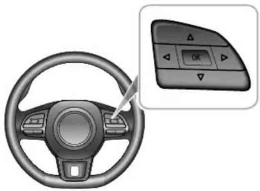
With the START/STOR switch ON/RUNNING position, the vehicle information display can be selected as follows:
natural_image
Interior view of a car steering wheel with a control panel showing OK button (no text or symbols on the dashboard)Press the LEFT/RIGHT/UP/DOWNbutton or the right handmultifunctionsteeringwheeltoshiftthedisplay items.
Press/P/DOW/Luttohighland multifunctionsteeringwheeltomakeadjustment.
PresKuttothegltandultifunction steeringwheeltoconfirmorlongpressOKbuttonto reset.
INSTRUMENTSANDCONTROLS
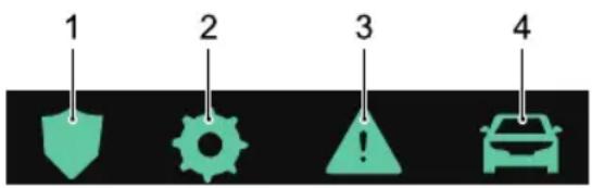
The vehicle information display contains the following information:
text_image
1 2 3 4I ActiveSafety
2Setting
3WarningInformation
4T ripComputer
ActiveSafety
Displaystheactivesafetyinformationofthevehicle.
Formoreinformation, pleasereferto "DrivingAssist System" in "Starting&Driving" section.
Setting
LuminanceLevel
Displaysthecurrentluminanceleveloftheinstrumentsand switches, this can be adjusted. There are 3 levels in total.
OverSpeedThreshold
Y oucansetthevalueofoverspeedthreshold.
ECO
ThisreferstotheECOdrivingmode,itcanbesettoOn orOff.
NextService
Display the current vehicle maintenance information. It can be reset by long pressing the OK button on the right hand multifunction steering wheel.
WarningInformation
Displaythewarninginformationorimportantnotesthat arecurrentlyrelevanttothevehicle.
TripComputer
INSTRUMENTSANDCONTROLS
The following information is available and can be selected for display.
- RangetoEmpty:displaystherangethatthevehiclecan travelbeforethefueltankisempty,thevalueofthe rangewillchangeafterrefueling.
- FuelConsumption:displaysthecurrentfuel consumptionwhentheengineisworking.
•DigitalSpeed:displaysthecurrentvehiclespeed. - CurrentJourney: displaystherange, duration, average speed and average fuel consumption since startup. These values will be reset after a period of power off. It can also reset by long pressing the OK button on the right hand multifunction steering wheel.
- Accumulated Total:displaystherange,duration, averagespeedandaveragefuelconsumptionsincethe lastreset.ItcanberesetbylongpressingtheOK buttonontherighthandmultifunctionsteeringwheel.
- I2VBatteryVoltage:displaytheI2VBatteryVoltage.
Pressure Monitoring display the current pressure dataforeachwheel.
WarningMessage
Warning messages prompt display the information message centre in the instrument pack. Any communications are displayed in 'popup' messages, these can be divided into the following categories:
- OperatingInstruction
•SystemStateInstruction
•SystemMalfunctionAlert
Please follow the instructions displayed in the popp message or in the case of awarning message, please refer to the relevant section of the owners manual to follow the correct instructions.
The following a reselection of warning messages that may appear in the information message centre.
INSTRUMENTSANDCONTROLS
| WarningMessageProcedure | |
| CruiseControlFaultConsultHandbook | Indicatesthatthecruisecontrol systemisfailed.Pleasecontacta localMGAuthorisedRepaireras soonaspossible. |
| EngineCoolantT emperatureHigh | Highenginecoolanttemperature couldresultinseveredamage.Stopthecarassoonas safetypermits,shutdownthe engineandcontactalocalMGAuthorisedRepairerimmediately. |
| EngineCoolantT emperatureSensorFaultConsultHandbook | Indicatesthattheengine coolanttemperaturesensor hasfailed.Pleasecontacta localMGAuthorisedRepairer immediately. |
| WarningMessageProcedure | |
| CheckEngine ConsultHandbook | Indicatesthatafailurehas occurredthatmayseverely damagetheenginehas occurred,stopthecaras soonassafetypermits,shut downtheengineandcontacta localMGAuthorisedRepairer immediately. |
| EngineFault ConsultHandbook | Indicatesthatafailurehas occurredthatwilleffectengine performanceandmissions.Please contactalocalMGAuthorised Repairerassoonaspossible. |
| 12VBattery ChargingSystem Fault | Indicatesthat12Vlow-voltage batterychargingsystemhas failed.PleasecontactalocalMG AuthorisedRepairerimmediately. |
INSTRUMENTSANDCONTROLS
| WarningMessageProcedure | |
| LowOilPressureConsultHandbook | Indicatesthattheoilpressureistoolow,whichmayresultinsevereenginedamage.Stopthevehicleassoonassafetypermitsandshutdowntheengine,checktheoillevelandcontactalocalMGAuthorisedRepairerimmediately. |
| StopStartSystemFaultConsultHandbook | IndicatesthattheStart-Stopintelligentfuelsavingsystemhasfailed.PleasecontactalocalMGAuthorisedRepairerassoonaspossible. |
| IgnitionSystemFaultConsultHandbook | Indicatesthatthepowermodehasfailed.PleasecontactalocalMGAuthorisedRepairerimmediately. |
| WarningMessageProcedure | |
| StartStopButtonFaultConsultHandbook | IndicatesthattheSTART/STOP switchhasfailed.Pleasecontact alocalMGAuthorisedRepairer immediately. |
| PassiveEntryFaultConsultHandbook | Indicatesthatkeylessentry functionhasfailed.Please contactalocalMGAuthorised Repairerassoonaspossible. |
| ABSFaultConsultHandbook | IndicatesthattheABSsystem hasfailed, andanti-lockbrake functionwillbedisabled.Please contactalocalMGAuthorised Repairerimmediately. |
INSTRUMENTSANDCONTROLS
| WarningMessageProcedure | |
| BrakeFaultConsultHandbook | Indicatestatafailurewithinthebrakingsystem,suchasbrakefluidlow/lossorElectronicBrake-forcedistributionfailurehasoccurred,stopthevehicleassoonassafetypermitsandshutdowntheengine,checkthebrakefluidlevelandcontacta localMGAuthorisedRepairerimmediately. |
| StabilityControlFaultConsultHandbook | IndicatesthatSCSsystemhasfailed.PleasecontactalocalMGAuthorisedRepairerimmediately. |
| TractionControlFaultConsultHandbook | IndicatesthatTCSsystemhasfailed.PleasecontactalocalMGAuthorisedRepairerimmediately. |
| EPBSystemFaultConsultHandbook | IndicatesthatEPBsystemhasfailed.PleasecontactalocalMGAuthorisedRepairerassoonas possible. |
| WarningMessageProcedure | |
| ParkBrakeForceNotEnough | IndicatesthattheEPBsystemhasfailedduringparking.PleasecontactalocalMGAuthorisedRepairerassoonaspossible. |
| AutoholdFaultConsultHandbook | Indicatesthatautoholdfunctionhasfailed.PleasecontactalocalMGAuthorisedRepairerassoonaspossible. |
| HillDescentControlFaultConsultHandbook | IndicatesthatHDCsystemhasfailed.PleasecontactalocalMGAuthorisedRepairerassoonaspossible. |
INSTRUMENTSANDCONTROLS
| WarningMessageProcedure | |
| EPSPerformance Reduced | Indicatesthattheelectricpower steeringsystemhasageneral failureandthatthesteering performancehasbeenreduced. Assoonasconditionspermit, safelystopthevehicleandswitch thevehiclepowersystemto theOFFposition.Afterashort while,switchthevehiclepower systemtotheON/RUNNING position,drivethevehiclea shortdistanceandmonitorthe operationofthesteering.If themessageisstilldisplayed orthesteeringassistance reduced,pleasecontacta localMGAuthorisedRepairer immediately. |
| WarningMessageProcedure | |
| EPSAssistanceFailureConsultHandbook | Indicatesthatthelectricpower steeringsystemhasfailed.Please contactalocalMGAuthorised Repairerimmediately. |
| SteeringAngleFaultConsultHandbook | Indicatesthatthesteeringangle sensorhasfailed.PleasecontactalocalMGAuthorisedRepairer assoonaspossible. |
| SteeringAngleUncalibratedConsultHandbook | Indicatesthatthesteeringangle sensorisnotcalibrated.Please contactalocalMGAuthorised Repairerassoonaspossible. |
| ESCLFaultConsultHandbook | IndicatesthattheESCLsystem hasfailed.Stopthecarassoon assafetypermits,shutdownthe engineandcontactalocalMGAuthorisedRepairerimmediately. |
INSTRUMENTSANDCONTROLS
| WarningMessageProcedure | |
| VacuumSystem Fault | Indicatesthatthevacuumsystem hasfailed.Pleasecontacta localMGAuthorisedRepairer immediately. |
| FuelSensorFault ConsultHandbook | Indicatesthatthefuelsensorhas failed.PleasecontactalocalMG AuthorisedRepairerassoonas possible. |
| AirbagFault ConsultHandbook | IndicatesthattheSRSsystem hasfailed,stopthecarassoon assafetypermits,shutdown the engineandcontactalocalMG AuthorisedRepairerimmediately. |
| AirbagLampFail | Indicatesthattheairbaglamphas failed.PleasecontactalocalMG AuthorisedRepairerassoonas possible. |
| WarningMessageProcedure | |
| PowerT ailgate SystemFault ConsultHandbook | Indicatesthattheelectrictailgate systemhasfailed.PleasecontactalocalMGAuthorisedRepairer assoonaspossible. |
| TPMSFaultConsult Handbook | Indicatesthatthetyrepressure monitoringsystem(TPMS)has failed.PleasecontactalocalMG AuthorisedRepairerassoonas possible. |
| FrontLeft/Front Right/Rear Left/RearRight T yreSensorBattery Low | IndicatingTPMSsensorlow battery.Pleasecontactalocal MGAuthorisedRepairerassoon aspossible. |
| ParkAssistSystem FaultConsult Handbook | IndicatesthatPDCsystemhas failed.PleasecontactalocalMG AuthorisedRepairerassoonas possible. |
INSTRUMENTSANDCONTROLS
| WarningMessageProcedure | |
| RearDriveAssist SystemFault ConsultHandbook | Indicatesthatthereardrive assistsystem(RDA)hasdetectedafault.PleasecontactalocalMGAuthorisedRepairerassoonas possible. |
| FrontCamera SystemFault ConsultHandbook | Itindicatesthatthefrontcamera hasdetectedafault.Please contactalocalMGAuthorised Repairerassoonaspossible. |
| FrontCamera CalibrationFailed | Indicatesthatthefrontview cameramodule(FVCM) calibrationhasfailed.Please contactalocalMGAuthorised Repairerassoonaspossible. |
| RADARCalibration Failed | Indicatesthattheradarmodule calibrationhasfailed.Please contactalocalMGAuthorised Repairerassoonaspossible. |
| WarningMessageProcedure | |
| LaneDepartureWarningSystemFaultConsultHandbook | Indicatesthatthelanedeparture warningsystem(LDW)has detectedafault.Pleasecontacta localMGAuthorisedRepaireras soonaspossible. |
| LaneKeepAssistSystemFaultConsultHandbook | Indicatesthatthelanekeep assistsystem(LKA)hasdetectedafault.PleaseconsultanMGAuthorisedRepairerassoonas possible. |
| ACCSystemFaultConsultHandbook | Indicatesthattheadaptivecruise controlsystem(ACC)has detectedafault.Pleasecontacta localMGAuthorisedRepaireras soonaspossible. |
| AutoEmergency BrakingSystemFaultConsultHandbook | Indicatesthattheautoemergency brakingsystem(AEB)has detectedafault.Pleasecontacta localMGAuthorisedRepaireras soonaspossible. |
INSTRUMENTSANDCONTROLS
| WarningMessageProcedure | |
| PedestrianAuto EmergencyBraking FaultConsult Handbook | Indicatesthattheautoemergency brakingsystemforpedestrians (AEBP)hasdetectedafault.PleasecontactalocalMGAuthorisedRepairerassoonas possible. |
| ForwardCollision SystemFault ConsultHandbook | Indicatesthattheforward collisionwarningsystem(FCW)hasdetectedafault.Please contactalocalMGAuthorised Repairerassoonaspossible. |
| MSAFault | IndicatesthattheManualSpeed Assist(MSA)functionhasfailed.PleasecontactalocalMGAuthorisedRepairerassoonas possible. |
| WarningMessageProcedure | |
| ISAFault | IndicatesthattheIntelligent SpeedAssist(ISA)functionhas failed.PleasecontactalocalMG AuthorisedRepairerassoonas possible. |
| MGPilotSystem FaultConsult Handbook | IndicatesthattheMGPilot systemhasdetectedafault.PleasecontactalocalMG AuthorisedRepairerassoonas possible. |
| eCallSystemFault ConsultHandbook | Indicatingtothedriverwitha yellowSOSwarninglampthat theeCallsystemisfaultyandnot operatingwithinitsparameters.TheSOSbuttonLEDstatus indicatorflashestwiceper second.Pleasecontactalocal MGAuthorisedRepairerassoon aspossible. |
INSTRUMENTSANDCONTROLS
| WarningMessageProcedure | |
| eCallSystemFailureConsultHandbook | Indicatingtothedriverwitha redSOSwarninglampthatthe eCallsystemhasfailedandnot capableofsupportinginthe eventofanaccident.TheSOS buttonLEDstatusindicatoris notilluminated.Pleasecontact alocalMGAuthorisedRepairer immediately. |
| WarningMessageProcedure | |
| eCallinProgress | Indicatingtothedriverwitha greenSOSwarninglampthat anemergencyservicescallis currentlyinprogress.TheSOS buttonLEDstatusindicator flashesoncepersecond. |
| AutoeCall DisabledConsult Handbook | Indicatingtothedriverwithared SOSwarninglampthatautomatic eCallserviceisdisabled.Please contactalocalMGAuthorised Repairertoreactivatethe automaticeCallfunction. |
INSTRUMENTSANDCONTROLS
WarningLightsandIndicators
Somewarninglampsilluminateorflashaccompaniedbya warningtone.Certainwarninglampswillbeaccompanied byamomentarywarningsymbolandtextmessage displayedintheinformationcentreintheinstrumentpack.
MainBeamIndicator-Blue

Withthemainbeamheadlampsturnedon, this
lampilluminates.
AutoMainBeamIndicator-Green

The indicator illuminates when the automain
beamfunctionisenabled.
DippedBeamOff-Yellow

Theindicatorilluminatestoindicatetothe driverthatthedippedbeamlampsareswitchedoffand thatitisnecessarytoturnthemon. The indicatorflashes
firstandthenremainsonafteraperiodoftimeoruntil thedriverswitchesthedippedbeamlampson.
DippedBeamIndicator-Green \*

Withthedippedbeamheadlampsturnedon,
thislampilluminates.
SideLampIndicator-Green

The indicator illuminates whenthesidelamps
areon.
RearFogLampIndicator-Y ellow

The indicator illuminates when therearfog
lampsareon.
INSTRUMENTSANDCONTROLS
FrontFogLampIndicator-Green
The indicator illuminates whenthefront fog
lampsareon.
DirectionIndicator-Green

Theleftandrightdirectionindicatorlampsare representedbydirectionalarrowsthatarelocatedatthe topoftheinstrumentpack.Whentheturningsignallamp flashes,thedirectionindicatorlamponthecorresponding sidealsoflashes.Ifthehazardwarninglampsareoperated, bothdirectionindicatorlampswillflashtogether.Ifeither directionindicatorlampintheinstrumentpackflashes veryrapidly,itindicatesthattheturningsignallightonthe correspondingsidehasfailed.
Note: Failureofasiderepeaterlampwillhaveno effectontheflashfrequencyofdirectionindicator lamp.
ECODrivingModelIndicator—Green \*

WiththeECOdrivingmodesettoON,ifthe
carisdrivinginECOmode,thislampilluminates.Ifthe ECOdrivingmodedisplayissettoOFForthecarisnot drivinginECOmode,thislampdoesnotilluminate.
DrivingModelIndicator \*

Indicate the driving mode of the current
vehicle:NORMAL,SPORT,ECO,CUSTOMandSUPER SPORT.
Pleasereferto"DrivingMode"in"StartingandDriving"chapterformoreinformation.
CruiseControlIndicator-Green/Y ellow \*
Ifthecruiseisswitchedon, thecruisecontrol
systemwillenterintostandbystate,andtheindicator illuminatesinyellow.
INSTRUMENTSANDCONTROLS
Whenthecruise control system operates, this indicator illuminates green, indicating the cruise control system is activated.
Ifafailureinthecruisecontrolsystemisdetected, the indicatorwillflashinyellow.PleasecontactalocalMG AuthorisedRepairerassoonaspossible.
EngineCoolantT emperatureWarning-Red

Whentheenginecoolanttemperature
warninglampilluminatesred, it indicates that the coolant temperature is high. If the engine coolant temperature continues to be, the engine coolant temperature warning lamp will flash.
Highenginecoolanttemperaturecouldresultinsevere damage. Stopthevehicleandswitchofftheengineas soonassafetypermitsandcontactalocalMGAuthorised Repairerimmediately.
EngineMalfunctionWarning-Y ellow
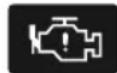
Thislampwillilluminateifanenginefaultoccurs ectengineperformedduringdriving.Stopthe switchofftheengineassoonassafetypermits talocalMGAuthorisedRepairerimmediately.
EngineEmissionsMalfunctionWarning-Yellow
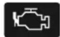
Ifthefuelfillercapisleftoff,notfastened fuelsystemfaultoccursoranenginefault willeffectengineperformanceandemission gthevehicle,thislampwillilluminate.Please fuelfillercap.Ifthelampkeepson,please AuthoriseRepairers
AlternatorMalfunctionWarning-Red

If this lamp illuminates after starting the vehicle, that the 12v battery charging system has a
INSTRUMENTSANDCONTROLS
failure.PleasecontactalocalMGAuthorisedRepairer immediately.
Incasesoflowbatterypower,thepromptmessageswill appearintheinformationcentre.Inthiscase,thesystem willlimitorturnoffsomeelectricaldevices,pleasestart thevehicletochargethebattery.
LowOilPressureWarning-Red
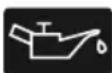
If this lamp illuminates after starting the vehicle, itindicate that the oil pressure is too low, which may result in severe engine damage. Stop the vehicle as soon as safety permits and SWITCHOFFTHE ENGINE IMMEDIATELY. Check the oil level (Referto "Engine Oil Level Check and TOPUP" in "Maintenance" chapter). Contact a local MG Authorised Repairer immediately.
Start-StopIntelligentFuelSavingSystem
StatusIndicator-Green

IftheStart-Stopintelligentfuelsavingsystemis activated, this lampilluminatestoinformthedriverthatthe engineiscontrolledbythesystem.
Start-StopIntelligentFuelSavingSystem
MalfunctionWarningLamp-Y ellow

IftheStart-Stopintelligentfuelsavingsystem hasafailure, thislampilluminates. Pleasecontactalocal MGAuthorisedRepairerassoonaspossible.
ElectricPowerSteering(EPS)/ElectricSteering ColumnLock(ESCL)Warning-Red/Yellow

Thewarninglampisusedtoindicateelectric
powersistesteerirfgilurelectronsteering columnlockfailure.
INSTRUMENTSANDCONTROLS
Whentislampilluminatesyellow, it indicates the electric power assisted steering system has a general failure and the performance is reduced. Please stop the car as soon as safety permits. If the lamp still illuminates after restarting the vehicle and driving for a short while, please contact a local MGA authorised Repairer immediately.
Whenthislampilluminatesred, it indicates the electric power assisted steering system has a general failure relevant to steering angles sensing. Please contact a local MGA authorised Repairer as soon as possible.
Whenthislampilluminatesredandflashes, it indicates the electric power assisted steeringsystem has a severe failure. Please contact local MGA authorised Repairer immediately.
Whenthelampilluminatesyellowandcontinuallyflashes accompaniedwithanaudiblewarning,itindicateshe electricsteeringcolumnlockhasafailure.Pleasecontact alocalMGAuthorisedRepairerassoonaspossible.Ifthis lampextinguishesafterflashingforawhile,itindicatesthat
thesteeringwheelislocked, pleaseattempttorotatethe steeringwheeltoremoveanyadverseloads.
T yrePressureMonitoringSystem(TPMS) Warning-Y ellow

Thewarninglampisusedtoindicatethatatyre ow,pleasecheckthetyrepressures.
If this lamp flashes first and then remains illuminated after a period of time, it indicates the system has a failure. Please contact a local MGA authorised Repairer as soon as possible.
ABSMalfunctionWarningLamp-Y ellow

ThislampilluminatestoindicateanABSfault.
PleasecontactalocalMGAuthorisedRepairerassoonas possible.
IfanABSfailureoccurswhiledriving, ABSwillfunction abnormally, butnormalbrakingwillstillbeavailable.
INSTRUMENTSANDCONTROLS
PleasecontactalocalMGAuthorisedRepairerassoonas possible.
HillDescentControl(HDC)ON/Malfunction Warning-Green/Y ellow
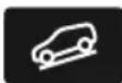
WiththeHDCswitchpressed,ifthelamp
illuminatesgreen, it indicates the HDC system has entered the Standbymode. Whenthe lampflashes green, it indicates that the system is currently under the control of HDC. Pressthe HDC switch again, the lamp extinguishes, it indicates the HDC function is deactivated.
IfaHDCrelatedsystemsuffersafailure, this lamp illuminates yellow. Please contact a local MGA authorised Repairer as soon as possible.
If this lamp illuminates yellow and flashes, it indicates that the brakesystem is too hot and the HDC system is disabled.
StabilityControl/T ractionControlSystem WarningLamp-Y ellow
Thislampilluminatestoindicatethatthereisa system.PleasecontactalocalMGAuthorised mediately.
If this lamp flashes during driving, it indicates the system is operating to assist the driver.
StabilityControl/T ractionControlSystemOFF WarningLamp-Y yellow
If the stability control/traction control system off manually, this warning lamp will illuminate.
BrakeSystemMalfunctionWarningLamp-Red

Thislampilluminatestoindicateafailurewith systemsuchasbrakefluidlossorelectronic distributionfailure.
Pleasestopthevehicleassoonassafetypermits,shutdown theengine,checkthebrakefluidlevel(referto"BrakeFluid CheckandT opUp"in"Maintenance"section)andcontact alocalMGAuthorisedRepairerforserviceimmediately.
SeatBeltUnfastenedWarning-Red

Thelampilluminatesorflashestoindicate
that theseatbeltforthedriverorthepassengerremains unfastened.
AirbagWarningLamp-Red

ThislampilluminatestoindicateaSRSfailureor seatbeltfailurehasbeendetected.Inthiscase,pleasestop thevehicleassoonassafetypermits,shutdowntheengine immediately,andcontactalocalMGAuthorisedRepairer forserviceattheearliestopportunity.Failureretofollow theabovemayresultintheSRSorseatbeltnotworking correctlyintheeventofacrashoraccident.
Anti-theftSystemWarning-Red

Ifnovalidkeyisdetected,thislampilluminates usethecorrectkeyorputthesmartkeyat thebottomofthecentreconsolecupholder.Forspecific position, pleasereferto"AlternativeStartingProcedure" of"StartingtheEngine"in"Starting&Driving"chapter.
Iftheremotekeybatterypowerislow, thislampflashes.
Pleasereplaceitassoonaspossible.
ElectronicParkingBrake(EPB)/AutoHold
StatusIndicator-Red/Green

If this lamp illuminates red, it indicates the EPB
systemisenabled.Ifthislampilluminatesredandflashes,it indicate that the EPB system has a failure. Please contact a local MGA authorised Repairer as soon as possible.
Whentheautoholdsystemisoperatingtoassistthedriver, thislampilluminatesgreen.
INSTRUMENTSANDCONTROLS
ElectronicParkingBrake(EPB)System
MalfunctionWarningLamp-Y ellow

lfelectronicparkingbrakesystemfailureis detectedorthesystemisunderdiagnosis, the lamp will illuminate. Please contact a local MGA authorised Repairer as soon as possible.
LowFuelWarningLamp-Yellow

Thewarninglampilluminatesyellowwhenthe fuelremaininginthefueltankislow.lfpossible,please refuelbeforethelowfuelwarninglampilluminates.
Whenthefuellevelcontinuestofall, thislampflashes. Whenfuelisaddedtothetankandthefuellevelrises abovethealertlimit,thislampextinguishes.lfitdoesnot extinguish,pleasecontactalocalMGAuthorisedRepairer forserviceassoonaspossible.
Note: Whendrivingonsteeporroughroadswhilethe fuellevelislow, the warninglampmayilluminate.
SystemFaultMessagesIndicator-Y ellow

Thisindicatorisusedtoalertthedrivertothe factthatthereisawarningstoredinthevehicleIPKsystem. Pleasereferto"InformationCentre"inthissectionfor thesefailures.
LaneDepartureWarningSystemIndicator-
Green/Y ellow
ThislampwillilluminateyellowwhentheLane DepartureWarningfunctionisenabled,thelampwill extinguishwhenthefunctionisdisabled.
ThislampwillilluminategreenwhentheLaneDeparture Warningfunctionisactivated.
IftheLaneDepartureWarningSystemisnotableto functionnormallythelampwillflashyellowandthen remainonafteraperiodoftime.Pleasecontactalocal MGAuthorisedRepairerforserviceassoonaspossible.
Formoreinformation, pleasereferto "LaneDeparture WarningSystem(LDW)" in "Starting&Driving" section.
LaneDeparturePreventionSystemIndicator-Green/Yellow
ThislampwillilluminateyellowwhentheLane
DeparturePreventionfunctionisenabled,thelampwill extinguishwhenthefunctionisdisabled.
ThislampilluminatesgreenwhentheLaneDeparture Preventionfunctionisactivated.
If the Lane Departure Prevention System is not able to function normally the lamp will flash yellow and then remain on after a period of time. Please contact local MG Authorised Repairer.
Formoreinformation, pleasereferto "LaneDeparture PreventionSystem(LDP)" in "Starting&Driving" section.
LaneKeepingAssistSystemIndicator-
Green/Y ellow
ThislampwillilluminateyellowwhentheLane
KeepingAssistfunctionisenabled,thelampwillextinguish whenthefunctionisdisabled.
ThislampilluminatesgreenwhentheLaneKeepingAssist functionisactivated.
If the Lane Keeping Assist System is not a tablet of function normally the lamp will flash yellow and then remain on after a period of time. Please contact a local MGA authorised Repairer.
Formoreinformation, pleasereferto "LaneKeepingAssist System(LKA)" in "Starting&Driving" section.
MGPilotSystemIndicator-Green/Y ellow \*
ThislampwillilluminateyellowwhentheMG
Pilotfunctionisenabled, the lampwillextinguish when the function is disabled.
INSTRUMENTSANDCONTROLS
ThislampilluminatesgreenwhentheMGPilotfunctionis activated.
If the MGPilotSystem is not a table to function normally the lamp will flash yellow and then remain on after a period of time. Please contact a local MGA authorised Repairer as soon as possible.
Formoreinformation, pleasereferto "MGPilotSystem" in "Starting&Driving" section.
ForwardCollisionAssistSystem
(FCW/AEB/AEBP)Indicator-Y ellow
Thislampwillilluminateyellowwhenoneofthe forwardcollisionassistsystem(FCW/AEB/AEBP)functions isdisabled.
Whenalloftheforwardcollisionassistsystem (FCW/AEB/AEBP)functionsareenabled,iftheindicator remainson,itindicatesthesystemisnotabletofunction normally.PleasecontactalocalMGAuthorisedRepairer as soonaspossible.
Formoreinformation, pleasereferto "ForwardCollision WarningSystem(FCW)" and "AutomaticEmergency BrakingSystem(AEB) and AutomaticEmergency Braking System for Pedestrians(AEBP)" in "Starting&Driving" section.
ManualSpeedAssistSystemIndicator
Green/Y ellow

Thlampilluminatyellowwhethe
ManualSpeedAssistfunctionisenabled,thelampwill extinguishwhenthefunctionisdisabledrspecific operation,pleasereferto"SpeedAssistSystem(SAS)"in "Starting&Driving"sectionfthecurrentspeedofthe vehicleisabovethemaximumvalueallowedbythesystem thevehicleremainsinthestandbystateandthelampwill illuminateyellow.
ThislampilluminatesgreenwhentheManualSpeedAssist functionisactivated.
If the Manual Speed Assist System is not a table of function normally the lamp will flash yellow and then extinguish.
INSTRUMENTSANDCONTROLS
Pleasetrytoreinstatethisfunction.Ifthisfunctioncannot beswitchedon,pleasecontactalocalMGAuthorised Repairerassoonaspossible.
Formoreinformation, pleasereferto "SpeedAssistSystem (SAS)" in "Starting&Driving" section.
IntelligentSpeedAssistSystemIndicator-Green/Y ellow

Thislampwillilluminateyellowwhenthe
IntelligentSpeedAssistfunctionisenabled, the lamp will extinguish when the function is disabled.
ThislampilluminatesgreenwhentheIntelligentSpeed Assistfunctionisactivated.
If the Intelligent Speed Assist System is not a table of function normally the lamp will flash yellow and then extinguish. Plesetry to reinstatement this function. If this function cannot be switched, please contact local MGA authorised Repairer as soon as possible.
Formoreinformation, pleasereferto "SpeedAssistSystem (SAS)" in "Starting&Driving" section.
ManualSpeedAssistSystemSpeedIndicator
ThislampwillilluminatewhentheManualSpeed
Assistfunctionisenable'NNN'denotesthecurrent settingvalueofthespeedlimit.Ifthereisnospeedlimit valuethelampwilldisplay'—'.
SpeedLimitSignIndicator-Red

'NNN'denotesthespeedvalueofspeedlimitlyrecognised.Ifthereisnospeedlimitvalueelampwilldisplay'—'.
WhentheIntelligentSpeedAssistfunctionisactivatedor SLIFWarningfunctionisenabled,thelampwillflashifthe speedlimitvalueisexceeded,pleaseslowdown.
INSTRUMENTSANDCONTROLS
SpeedLimitSignAdditionalInformation
WarningLamp-Yellow

Thislampwillilluminatewhenthespeedlimit
signcurrentlyrecognisedhasadditionalinformation.Please payattentiontoit.
NationalSpeedLimitSignIndicator

Whenthenationalspeedlimitsignisidentified,
andthespeedlimitinformationfunctionorintelligent speedassistfunctionisenabled,thislampilluminates.
Formoreinformation, pleasereferto "SpeedAssistSystem (SAS)" in "Starting&Driving" section.
AdaptiveCruiseControlSystemIndicator-
Y ellow/Green\*
If the Adaptive Cruise function is enabled, the
Adaptive Cruise Control System will enter the stand by state, the lamp illuminates yellow.
When the Adaptive Cruise Control System operates, the lamp will illuminate green, this indicates that the Adaptive Cruise Control System is activated.
AdaptiveCruiseControlSystemMalfunction IndicatorLamp-Y ellow\*
ThislampwillilluminateifaAdaptiveCruise
ControlSystemfailureisdetected.PleasecontactalocalMGAuthorisedRepairerassoonaspossible.
INSTRUMENTSANDCONTROLS
RearDriveAssistSystemIndicator-Y yellow
Ifthereardriveassistsystemisturnedoff,this
lampilluminateswithpromptmessages.
If thereardriverassistsensorsareobscured, thislamp illuminateswithpromptmessages.
Whenreardriveassistsystemhasafailure, thislamp illuminateswithpromptmessages.Pleasecontactalocal MGAuthorisedRepairerassoonaspossible.
Referto"RearDriverAssistanceSystem"in"Startingand Driving"chapterformoreinformation.
eCallSOSIndicator-Red/Y ellow/Green

If the system is ready and an emergency services
call(eCall)isinprogress,theindicatorilluminatesgreen.
Ifthesystemisstillcapableofsendingoutvehicle informationmessagegetothecallcentre,butothereCall capabilitiesarelimitedduetoafaultinthesystem,the indicatorwillilluminateyellow.IftheeCallsystemhas
failedandnotoperational,theindicatorilluminatesred.If theyelloworredindicatorisilluminatedpermanentlyafter systemself-test,pleasecontactalocalMGAuthorised Repairerimmediately.
ParticulateFilterWarningLamp-Y ellow

Whentislampilluminatesyellow,itindicates
thattheparticulatefilterrequiresregeneration.Please drivethevehicleabove45mphuntilthelightisnolonger illuminated,andthennormalusagecanberesumed.
Whenthislampflashes, it indicates that the particulate filter is full. Please contact a local MGA authorised Repairer immediately. Plesenote if the warning is ignored, the vehicle will enter a reduced performance mode and may subsequently be immobilised.
Pleasereferto"CatalyticConverterandParticulateFilter" in "Starting&Driving" section.
INSTRUMENTSANDCONTROLS
LightsandSwitches
MasterLightSwitch
text_image
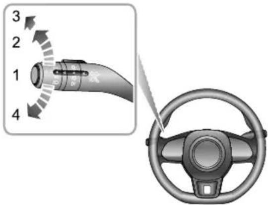
3 2 1 4IAUTOLamp
2SideLamp/SwitchBacklights
3Headlamp
4LightOff
AUTOLamp
Whenthestart/stopswitchisintheACCposition,the autolightingsystemdefaultstotheONposition(1).The AUTOlightingsystemwillautomaticallyswitchtheside lampsandswitchilluminationonandoffaccordingtothe intensityofcurrentambientlight.
Withthestart/stopswitchintheON/RUNNINGposition, theAUTOlightingsystemwillautomaticallyswitchtheside lamps, switchillumination and dipped beamheadlampson and off according to the intensity of current ambient light.
Note: This function uses alightsensorthat monitors exterior ambient light levels. Thesensorforsome models is fitted centrally to the fasci panel near the windscreen. DONOT mask cover this area. Failure toadheret this may result in headlamps operating when not necessary.
SideLampandSwitchIllumination
T urnthemasterlightingswitchtoposition2tooperate thesidelampsandswitchillumination.Withthestart/stop switchintheOFFpositionifthelightingswitchisin
position2andthedriver'sdooropenedanaudiblewarning willsoundtoalertthedriver,thesidelampswillremain on.Themessagecentrewillprompt"LightsOn"(model dependant).
DippedHeadlamps
Whenthestart/stopswitchisintheON/RUNNING positionturnthemasterlightingswitchtoposition3 tooperatethedippedbeamheadlamps,sidelampsand switchillumination.
LightsOff
T urnthemasterlightingswitchtoposition4, this will switchoffalllamps, releasing the switch will allow it to return to the AUTO switch position.
DaytimeRunningLamps
Thedaytimerunninglampsturnonautomaticallywhen thestart/stopswitchisinpositionON/RUNNING.When thesidelampsareswitchedon,thedaytimerunninglamps extinguishautomatically.
WelcomeLight
Whenthecaris unlocked, the system will automatically enable the welcomelight function according to the intensity of the current ambient light. The daytime mode will illuminate the sidelamps, while then night modewill illuminated the dipped beams, sidelamps and puddle lamps.
FollowMeHome
Afterthestart/stopswitchisturnedoff, pullthelighting levertowardsthesteeringwheel. FollowMeHome functionisenabled. Dippedbeamsandsidelampswill illuminate. FollowMeHomecanbesetthrough "Car" on theinfotainmentdisplay.
FindMyCar
Afterthevehiclehasbeenleftinalockedconditionin severalminutes,pressingthelockbuttonagainonthe remotekeywillenabletheFindMyCarfunction.This functionwillidentifythecarbymeansofanaudibleand visualalert.PressingtheLockbuttonontheremotekey againwillsuspendthisoperation.Atthistime,pressthe
INSTRUMENTSANDCONTROLS
Unlockbuttonontheremotekeywillcancelthisoperation. FindMyCarcanbesetthrough "Car" on theinfotainment display.
HeadlampLevellingAdjustment
natural_image
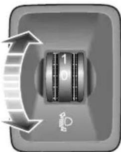
Close-up of a mechanical knob with a dial and directional arrows indicating rotation (no text or symbols)Position0istheinitialpositionoftheheadlamplevelling adjustmentswitch. Theheadlamplevellingcanbeadjusted asperthefollowingtableaccordingtothevehicleload.
| Location | Load |
| 0Driver,ordriver&frontpassenger | |
| 1 | Alltheseatsoccupiedwithnoload |
| 2 | Alltheseatsoccupiedplusanevenlydistributedloadintheboot |
| 3 | Driveronly,plusanevenlydistributedloadintheboot |
INSTRUMENTSANDCONTROLS
LightingLeverSwitch

T akecarenottodazzleoncomingvehicles whendrivingusingmainbeamheadlamps.
text_image
Diagram showing a car's electrical plug with four labeled parts and a steering wheel viewDirectionIndicators
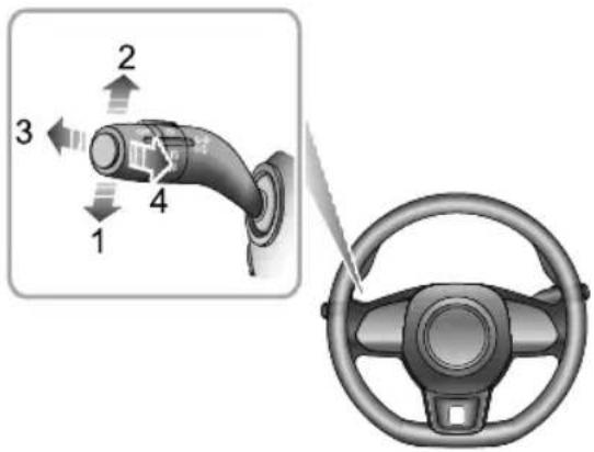
MovetheleverdowntoindicateaLEFTturn(1).Movethe leveruptoindicateaRightturn(2).Thecorresponding
GREENindicatorlampintheinstrumentpackwillflash whentetheturnsignallampsareworking.
Rotatingthesteeringwheelwillcanceltheindicator operation(smallmovementsofthesteeringwheelmay notoperatetheselfcancelling).T oindicatealanechange, movetheleverbrieflyandrelease,theindicatorswillflash threetimesandthencancel.
Main/DippedBeamHeadlampsSwitching
Withthestart/stopswitchintheON/RUNNINGposition andthemasterlightingswitchturnedtoposition3,orthe autofunctionhasswitchedthelightson,pushthelever(3) towardstheinstrumentpaneltoturntheheadlamphigh beamson.Thehighbeamindicatorlampintheinstrument packwillilluminate,pressthelever(3)againtoswitchthe headlampstolowbeam.
MainBeamFlash
T obrieflyflashthemainbeamonandoff,pullthelever(4) towardsthesteeringwheelandthenrelease.
INSTRUMENTSANDCONTROLS
SmartMainBeamSystem

Smartmainbeamsystemservesonlyasan auxiliaryfunction. Thedriverstillneedsto checkthestatusofthefrontlamps, andturn onthefrontlampswhennecessary.
Forexample: Themainbeammaynotbe turnedoffautomaticallyinthefollowing cases,thusthemanualswitchingbetween themainbeamanddippedbeamisrequired:
-
Thewindscreenisdirty,brokenor obstructedbyotherobjectsblockingthe viewofthesensor.
•Thelampsofothervehiclesaremissing, damaged, blockedorpartiallyblocked or cannot be detected for some other reasons.
•Thelampsofothervehiclesareobscured orpartiallyobscuredbysmoke,fog,snow, watersprayoranyotherconditionsthat effectvisibility. -
Whenpedestrians, non-motorvehicles and other objects with no obvious lightor reflected light are encountered.
- Whentheheadlampsandtaillampsof othervehiclescannotbedetecteddueto thesensorviewisimpaireddueundulating roadconditionssuchasbends,dipsorhills.
- Whenthecarisdrivingonthewinding roadormountainousroad. Incasesofanyoftheaboveconditions(but notlimitedto)smartmainbeamoperation maybesuspended,itmaybenecessaryto operatethemainbeamlampsmanually.
Thesmartmainbeamsystemusesthefrontviewcamera todetectthelightintensityofthevehicleahead. Themain beamlampscanbeswitchedonoroffautomaticallyby thesystemwhenthesurroundingsaredarkandnolight detected.
To enable the smart main beams system, the following condition should be met:
INSTRUMENTSANDCONTROLS
I Themasterlightingswitchmustbeinthe'Auto' positionandthedippedbeamlampsswitchedonvia automaticcontrol.
2Thevehicleisrunningandthespeedisabove25mph (40km/h)
3Thefront/rearfoglampsareNOTswitchedon.
Whenthesmartmainbeamsystemisenabled,theauto mainbeamindicatorontheinstrumentpackilluminates.
Themainbeamlampswillremainonunderautomatic controluntilanyofthefollowingconditionsoccur:
- Thesystemdetectstheheadlampsofapproaching vehicles.
- Thesystemdetectsthetaillampsofvehiclesahead.
- Thesurroundingsbecomebrightenoughnottorequire mainbeam.
- The vehiclespeeddrops below the 25 mph (40 km/h) threshold.
Thesystemwilltemporarilysuspendthesmartmainbeam functiononcethefollowingconditionsaremet:
With the smart main beam system enabled, instantaneously pull the lightinglevertoward the steering wheel, the smart main beam function will be temporarily suspended, it will automatically bere-instated when the switch lever is released.
Note: Continuously operating themainbeamswitch within2secondswillretainthemainbeamlamps underautomaticcontrol, and the system will not exit the smartmainbeam function.
IMPORTANT
Thesmartmainbeamfunctionusesdatafromthefront viewcamera,alwayskeepthewindscreencleanand freefromresidueinthisareatomaintainoptimum performanceofthissystem.Anydamageinthisarea, suchasstonechipsmustberepairedattheearliest convenience.
INSTRUMENTSANDCONTROLS
FogLampSwitch

Foglightsshouldonlybeusedwhenvisibility isbelow100m-otherroaduserscouldbe dazzledinclearconditions.
text_image
Diagram showing car steering wheel control with labeled parts and directional arrowsFrontFogLamps
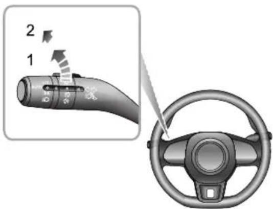
Withthestart/stopswitchintheON/RUNNINGposition andthesidelampson,turnthefoglampswitchtoposition
I toturnonthefrontfoglamps. The indicator illuminates intheinstrumentpanelwhenthefrontfoglampsareon.
RearFogLamps
Withthestart/stopswitchintheON/RUNNINGposition andthefrontfoglampsturnedon,turnthefoglampbutton toposition2toturnontherearfoglamps,releasethe buttontoreturntoposition1.Theindicatorilluminates ontheinstrumentpanelwhentherearfoglampsareon.
HazardWarningLamps
Pressthehazardwarninglampbuttontooperate thehazardwarninglamps.Allturnsignallampsand directionindicatorlampswillflashtogether.Pressthe buttonagaintoswitchoffthehazardwarninglamp.All turnsignallampsanddirectionindicatorlampswillstop flashingforthelocationofhazardwarninglamp,refer totheillustrationof"HazardWarningDevices"under "EmergencyInformation".
INSTRUMENTSANDCONTROLS
WipersandWashers
FrontWindscreenWiperControls
text_image
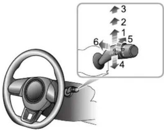
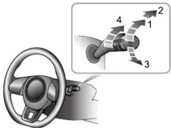
Diagram showing car steering wheel and valve mechanism with numbered directional arrows indicating motion or movement.Thewipersandwasherswillonlyoperatewhenthe start/stopswitchisinposition"ON/RUNNING".Operate thelevertoselectdifferentwipingmodes:
•Intermittentwipe(I)
•Slowspeedwipe(2)
•Fastspeedwipe(3)
•Singlewipe(4)
- Intermittentwipeintervaladjustment * /Rainsensor sensitivityadjustment * (5)
•Programmedwipe(6)
IntermittentWipe
BypushingtheleveruptothelIntermittentwipe position(1),thewiperswilloperateautomatically. TheintervalbetweenthelIntermittentwipescanbe increased/decreasedviatheswitch(5).Thisintervalwill alsochangewiththevehiclespeed.Asthevehiclespeed increases,thewipingintervaldecreases.Asthevehicle speeddecreases,thewipingintervalincreases.
Somemodelsareequippedwitharainsensorfittedtothe interiorrearviewmirrorbasetodetectvaryingamountsof waterontheoutsideofthewindscreenWithautomatic wipe,thevehiclewilladjustthewipingspeedaccordingto thesignalsprovidedbyrainsensof.urntheswitch(5) toadjustthesensitivityofrainsensor.Asthesensitivity increases,thewipingintervaldecreases.
Note: Immediately operating the wiperone time can be achieved by increasing the sensitivity of frainsensor.
INSTRUMENTSANDCONTROLS
Iftherainsensordetectscontinuousrainwater,the wiperwillkeepworking.Whenitisnotraining,itis recommendedtoswitchoffautomaticwipe.
SlowSpeedWipe
Bypushingtheleveruptotheslowspeedwipingposition (2), thewiperswilloperateslowly.
FastSpeedWipe
Bypushingtheleveruptothefastspeedwipingposition (3), thewiperswilloperateatfastspeed.
SingleWipe
Pressingtheleverdowntothesinglewipingposition(4) andreleasingwilloperateasinglewipe.Iftheleverisheld down(4),thewiperswilloperatecontinuouslyuntilthe leverisreleased.
Note: Whenthecarisstationary, if the bonnetis opened, the frontwiper/washer operation will be disabled.
IMPORTANT
- Avoidoperatingthewipersonadrywindscreen.
- Infreezingorextremelyhotconditions,makesure thatthewiperbladesarenotfrozenoradheredto thewindscreen.
- Inwinter, removesnoworicefromaroundthewiper armsandblades, includingthewipedareaofthe screen.
ProgrammedWipe
Pullingthelevertowardthesteeringwheel(6)willoperate thefrontwindscreenwashers. Afterashortdelay,the wipersvilkommenceoperatingconjunctionwithhe washers.
Note: Thewiperscontinueoperatingforafurther threwipesfethleveiseleasedAfteseveral secondsherovibfurthewipeaemovany fluiddrainingdownthescreen.
INSTRUMENTSANDCONTROLS
IMPORTANT
Ifthewashersfaltodeliverthescreenwashsolution (dirtoricemayhaveblockedthejets), releasethe leverimmediately. Thiswillpreventthewipers fromoperating, and the consequentriskof visibility beingimpairedbydirtsmearingacrosstheunwashed windscreen.
RearWindscreenWiperControls
text_image
Diagram showing car steering wheel and directional arrows indicating movement or flow, with numbered labels 1 to 4.Therearwipersandwasherswillonlyoperatewhen thestart/stopswitchisinthe"ON/RUNNING"position.
Operatethelevertoselectdifferentwipingmodes:
•Intermittentwipe(I)
•Washandwipe(2)
•Washandwipe(3)
•Wipeintervaladjustment(4)
INSTRUMENTSANDCONTROLS
Intermittentposition
If therearwiperswitchisturnedtointermittentwipe(1), therearwiperwilloperate.Itwillcomplete3continuous wipesbeforechangingtointermittentmode. Thetime periodbetweenthewipscanbeincreased/decreasedvia theswitch(4).
Washandwipe
T urntherearwindowwiperswitchtowashandwipe(2) positionandhold,therearwindowwiperandwasherwill operate,therearwindowwiperwipesquickly.releasethe switchallowingittoreturntointermittentwipe(1),the rearwindowwasherwillstopoperating.
T urntherearwindowwiperswitchtowashandwipe(3) andhold, therearwindowwiperandwasherwilloperate. releasetheswitchallowingittoreturntoOFFposition, therearwindowwasherwillstopoperating, andtherear windowwiperwipesfor3times,afterseveralseconds,the wiperwillwipeoncemoretoremovethewasherfluidon thewindscreen.
Note: Whenthetailgateisopened, rearwiper operationswillbedisabled.
Note: Whenthewindscreenwipersareswitchedon, if Reversegearisselected, therearwindowwiperwill operate.
INSTRUMENTSANDCONTROLS
SteeringSystem
AdjustmentofSteeringColumn

DONOTattempttoadjusttheheightor angleofthesteeringcolumnwhilethecaris inmotion. Thisisextremelydangerous.
natural_image
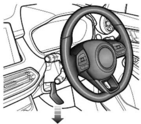
Interior view of a car showing steering wheel, dashboard, and steering wheel (no text or symbols)T oadjusttheangleorheightofthesteeringcolumntosuit yourdrivingposition:
I Fullyreleasethelockinglever.
2Holdthesteeringwheelinbothhandsandtiltthe steeringcolumnupordowntomovethewheelinto themostcomfortableposition.
3Pushorpullthesteeringwheeltowardsorawayfrom thebody.
4Onceaccomfortabledrivingpositionhasbeenselected, pullthelockingleverfullyuptolockthesteering columnintoitsnewposition.
INSTRUMENTSANDCONTROLS
ElectricPowerSteering

If the electric power steering fails or cannot operate the steering will appear very heavy, this will effect drivings safety.
Theelectricpowersteeringsystemonlyworkwhenthe vehicleisstarted. Thesystemoperatesviaamotorwith assistancelevelsautomaticallyadjustedbasedonvehicle speed,steeringwheeltorqueandsteeringwheelangle.
IMPORTANT
Holdingthesteeringwheelonfulllockforlongperiods willresultinareductioninpowerassistancecausinga heavierfeeltothesteeringforashortperiodoftime.
SteeringModeSwitching \*
Theelectricpowersteeringsystemprovides3different steeringmodes, pleasereferto"DrivingMode"inthe "Starting&Driving"section.
I Normal: provides moderate power assistance.
2Comfort:providesahighlevelofassistance,witha lightfeel.
3Sport: provides low level power assistance, with a heavier feel.
Note: Steeringmodeselectionsonlyavailablewhen thesteeringwheelisnotbeingturned.Anychanges madeinthisstatewillnottakeeffectuntilthesteering wheelisstraightahead.
ElectricPowerSteering(EPS)WarningLamps
See"WarningLightsandIndicators" under the "InstrumentsandControls" section.
If the battery has been disconnected for any reason, upon reconnection the warning lamp will illuminate yellow. Movement of the steering wheel from lock to lock will initial is the system and the lamp will be extinguish.
INSTRUMENTSANDCONTROLS
Horn
natural_image
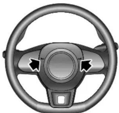
Top-down view of a car steering wheel with three blades and a central hub (no text or symbols)Pressthehornbuttonareaonthesteeringwheel(as indicatedbythearrow)tooperatethehorn.
Note: The vehicle horn press and the driver's airbag are located in close proximity on the steering wheel. The illustrations show the position of the horn (indicated by arrow), please ensure that you press
inthisareatoavoidanypotentialconflictwiththe operationoftheairbag.
IMPORTANT
T oavoidpossibleSRSissues, pleasedonotpresswith excessiveforceorhittheairbagcoverwhenoperating thehorn.
INSTRUMENTSANDCONTROLS
RearviewMirrors
Thevehicleisfittedwithrearviewmirrors,theseconsistof adoormirrorfittedtoeachdoorandacentrallymounted interiormirror .Rearviewmirrorsreflectsituationsbehind oronbothsidesofthevehiclethusexpandingthedriver's fieldofvision.
Therearviewmirrorsaresafety-criticalparts.Properuse andreasonablemirrorangleadjustmentcanimprovethe driver'sdrivingsafetyandcomfort.
ExteriorDoorMirrors
Note: Objectsviewedinexteriordoormirrorsmay appearfurtherawaythantheyactuallyare.
Themirrorscanbefoldedbackelectricallytowardsthe sidewindowsintoa'park'positiontoenablethecarto negotiatenarrowopeningsandavoidcollisions.
Inadditiontothefoldingfunction,themirrorangleofthe exterioriodormirrorscanbeelectricallyadjusted.
MirrorGlassHeating
Thedoormirrorshaveintegralheatingelementswhich disperseiceormistfromtheglass.Theheatingelements operatewhiletheHeatedRearWindow isswitchedon.
Note: The heating element so frear window and mirror will only work when the engine is running.
PowerFolding
natural_image
Diagram showing a car's door handle and control panel with an arrow indicating left-hand rule (no text or symbols present)INSTRUMENTSANDCONTROLS
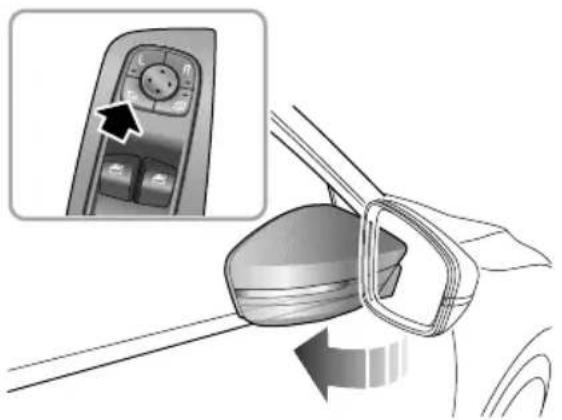
Pressingtheswitch(arrowed)onthecombinationswitch inthedriversideswitchpanelwillelectricallyfoldthe exteriordoormirrors.Pressingthisswitchagainwill restorethemirrorstotheiroriginalposition.
While unlocking/lockingthevehicle,theexteriordoor mirrorswillbedeployed/foldedautomatically.This functioncanbesetintherelevantinterfaceonthe infotainmentdisplay.
Note: Electrical folding doormirrorsthath have been moved from their positions by manual or accidental means must be reset by operating the folding switch to completely fold and unfold them mirror sonetime.
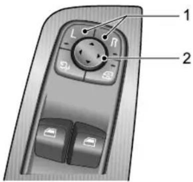
ElectricAdjustmentofMirrorGlass
text_image
1 2- Presstheleft(L)orright(R)switch(I)toselectthe leftorrightexteriordoormirror.Theindicatorlamps withintheswitches(I)willilluminatewhenselected.
- Pressoneofthe4arrowsofthecircularswitch(2)to adjusttheangleoftheexteriordoormirror.
- PresstheLorRswitch(1)again, thecorresponding indicator, xiktinguialdeerror
INSTRUMENTSANDCONTROLS
adjustmentoperationwillbestopped. Thisistoavoid accidentaladjustmentofmirrorangleonceadjustments hasbeenmade.
IMPORTANT
- Exteriordoormirrorsareoperatedbyelectrical motors. Operatingthemdirectlybyhandmay damagetheinternalcomponents.
- Washingorflushingexteriordoormirrorswithhigh pressurewaterjetsorcarwashesmayresult in electricalmotorfailure.
PuddleLamp \*
Puddlelampsarelocatedwithinthelowerhalfofthe doormirrors.Forinformationonhowtooperatethese puddlelampsplesasereferto"LightingandSwitches"in "InstrumentsandControls"chapter .
AutomaticAnti-dazzleInteriorRearview Mirror
natural_image
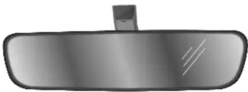
Top-down view of a car rearview mirror (no text or symbols visible)When the START/STOP switch is in the ON/RUNNING position, the automatic anti-dazzle function is switched on automatically. When following vehicle's headlamp could dazzle the driver, the lights sensor activates the anti-dazzle function.
Theautomaticanti-dazzlefunctioncanbeinhibitedif:
- Thelightfromthevehiclebehindisnotseenbythelight sensoronthemirror.
- Reversegearisselected.
INSTRUMENTSANDCONTROLS
Note: Attaching filmorobjectsontherearwindow may have influences on the function of the automatic anti-dazzlefunction.
INSTRUMENTSANDCONTROLS
Sunvisor

Thevanitymirroronthedriversideshould onlybeusedwhenthecarisstationary.
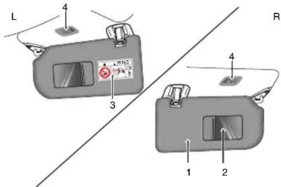
Sunvisor(1)andvanitymirrors(2)arearrangedontheroof aheadofboththedriverandthefrontpassenger.Certain modelsarefittedwithvanitymirrorlights(4)depending onthevehicleconfiguration.
text_image
L 4 3 R 1 2 4Pullthesunvisordownwardtousethevanitymirror.If theroofhasvanitymirrorlights,thevanitymirrorlightis switchedonwhenthecoverisopened,anditisswitched offwhenthecoverisclosed.
Note:Warningsandinstructionsontheuseofachildrestraint(3)areattachedtobothsidesofthepassengersunvisor.
NEVERusearearwardfacingchildrestraintsonaseat protectedbyanACTIVEAIRBAGinfrontofit,DEATH orSERIOUSINJURYtotheCHILDcanoccur.Refer to'DisablingthePassengerAirbag'.
INSTRUMENTSANDCONTROLS
Windows
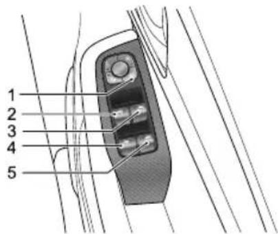
PowerOperatedWindowSwitch
text_image
1 2 3 4 5I RearWindowIsolationSwitch
2FrontLeftWindowSwitch
3FrontRightWindowSwitch
4RearLeftWindowSwitch
5RearRightWindowSwitch
WindowOperation

Ensurechildrenarekeptclearwhenraising orloweringawindow.Improperuseor activationoftheelectricwindowsbychildren couldcauseseriousharmorevendeath.It istheresponsibilityofthedriverandadult passengerstoensurethatwhencarrying childrenthenecessaryrstepsaretaken toisolatethewindowoperatThis shouldincludeswitchingofftheignitionand removingthesmartkeyfromthevehicle whenchildrenareleftaloneinthevehicle.
Presshewitch(2\~5)bowethewindowandpull theswitchtoraisethewindow.Releasetheswitch,the windowwillstopmoving(unlessin"one-touch"mode).
Note: The front and rear passenger windows can also be operated by individual window switches, mounted on a chord the window switch will not function if the rear window is isolated when the driver door has been activated.
INSTRUMENTSANDCONTROLS
Note: Whenthestart/stopswitchisintheACCor ON/RUNNINGposition, thepowerwindowscanbe operated (doorsshouldbeclosed).
RearWindowIsolationSwitch
Presstheswitch(1)toisolatetherearwindowcontrols(an indicatorlampintheswitchilluminates),andpressagainto restorecontrol.
Note: It is recommended that you ISOLATE therear window switches when carrying children.
OneT ouchDown
Thewindowswitches(2 \~ 5)are2stageswitches,short presstothesecondstage,thewindowwillenteronetouch modeandautomaticallyfullyopen.Whenthewindowis movingdown,itsmovementcanbestoppedatanytimeby pressingtheswitchagain.
OneTouchUpwithAnti-T rap
SomewindowswitcheshavetheOneTouchUpfunction. Brieflypullupthewindowcontrolswitch(2)tothesecond stage, the corresponding window automatically ascend to fully closed. Window movement can best stop at any time by operating these switch again.
The 'Anti-T rap' functionisasafetyfeaturewhichprevents thewindowfromfullyclosingifanobstructionissensed. In this case, the windowwillmovedownsothattheobstacle can betakenout.
Note: DONOToperatethepowerwindowcontrols continuouslyseveralmechortiframe, insomecasesthepowerwindowcontrolsmaybe disabledtoprotectthemotofthisoccurs, please waitafewsecondsuntilthemotorcoolsdown.
Nothbattenpuffurinliftingnd loweringofthewindow,OneT ouchUpandAnti-Trap modemaybenotoperational,inthiscase,fullyopen thewindow,thenraisethewindowtothefullyclosed positionbyliftingtheswitchbrieflyandconsecutively. Whenthewindowisfullyclosed,holdtheswitchin theclosepositionforafurther5seconds.OneT ouch UpandAnti-Trapmodewillberesumed.
INSTRUMENTSANDCONTROLS
"LazyLock"Function \*
The "LazyLock" function can open or close all the windows by using theremote key from outside the vehicle as long as it is with indetection range.
Pressandholdtheremotekeyunlockbuttonuntilthe windowsstarttoopen,releasetheunlockbutton,all windowswillopenfully.Withthewindowsopen,press andholdtheremotekeylockbuttonuntilthewindows starttoclose,releasethelockbutton,thewindowswill completelyclose.
INSTRUMENTSANDCONTROLS
Sunroof\*
Instructions

DONOTallowpassengerstoleanoutofan opensunroofwhilstthevehicleisinmotion. Injuriesmayoccurfromobjectssuchastree branches.
- Avoidfully opening the sunroof during grain showers.
- Itisadvisednottoopenthesunroofathighspeeds.
•Wherepossible,pleasecleananyresidualwateror raindropsoffthesunroofpriortoopening.Failureto dosomayresultinwaterenteringthecar.
• DONOTuseabrasivematerialstocleanthesunroof glass.Usealcoholbasedsolvent.
• DONOTholdtheoperatingswitchintheopen/close positionforanylengthoftimeafteroperationis complete, thiscoulddamagetheelectricalcomponents. - Cleanthesunroofregularlytomaintainoperationand performance. VisitanMGAuthorisedRepairerfor serviceasrequired.
SunroofOperation

Safetyofthevehicleoccupantsmustbe observedatalltimes.DONOTallowlimbsto beplacedinthemovingpathofthesunroof atanytime,injurymayoccur.
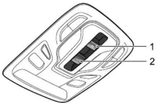
text_image
Technical diagram of a device casing with labeled parts 1 and 2WhetART/STORwitchaC6r
ON/RUNNING,youcanoperatethesunroof.
Thesunroofconsiststwopiecesofglassandonesunshade. Thronglassabopenedbylidingtiltinghe rearoneisfixedandcannotbeopened,andthesunshade
INSTRUMENTSANDCONTROLS
canslideopen.Switch l isusedtooperatethesunroof sunshade,andswitch2isusedtooperatethesunroofglass. Themethodbywhichthesunroofwillopenfunctionis identifiedbytheiconsontheswitches.
SunroofGlassOperation
OpentheSunroofGlassbyTilting
text_image
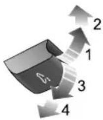
1 2 3 4Pushthesunroofglassswitchupwardtothelstposition(1) andhold,thesunroofwillautomaticallytiltopen.Y oucan stopthemovementofthesunroofatanytimebyreleasing theswitch.Pushtheglassswitchwithslightlyharderforce tomovetheswitchtoits2ndposition(2)andthenrelease,thesunroofwillautomaticallyopencompletely.
ClosetheSunroofGlassbyTilting
Pullthesunroofglassswitchdownwardtothe1stposition (3)andhold,thesunroofwillautomaticallyclose.Y oucan stopthemovementofthesunroofatanytimebyreleasing theswitch.Pulltheglassswitchwithslightlyharderforce tomovetheswitchtoits2ndposition(4)andthenrelease, thesunroofwillautomaticallyclosecompletely.
ClosetheSunroofGlassbySliding
text_image
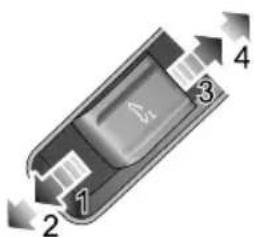
1 2 3 4Pushthesunroofglassswitchforwardtothe1stposition (1)andhold,thesunroofwillautomaticallyclose.Y oucan stopthemovementofthesunroofatanytimebyreleasing theswitch.Pushtheglassswitchforwardwithslightly harderforcetomovetheswitchtoits2ndposition(2)
INSTRUMENTSANDCONTROLS
andthenrelease,thesunroofwillautomaticallyfullyclose. Youcanstopthemovementofthesunroofatanytimeby pushingtheswitchforwardagain.
OpentheSunroofGlassbySliding
Pushthesunroofglassswitchbackwardtothe1stposition (3)andhold,thesunroofwillautomaticallyslideopen. Y oucanstopthemovementofthesunroofatanytimeby releasingtheswitch.Pushtheglassswitchbackwardwith slightlyharderforcetomovetheswitchtoits2ndposition (4)andthenrelease,thesunroofwillautomaticallyopen fully.Y oucanstopthemovementofthesunroofatany timebypushingtheswitchbackwardagain.
SunroofSunshadeOperation
text_image
1 2 3 4OpentheSunshade
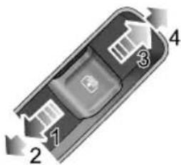
Pushthesunroofsunshadeswitchbackwardtothe1st position(3)andhold,thesunshadowwillautomaticallyslide open.Y oucanstopthemovementofthesunshadeatany timebyreleasingtheswitch.Pushthesunshadeswitch backwardwithslightlyharderforcetomovetheswitch toits2ndposition(4)andthenrelease,thesunshadowwill automaticallyopenfully.Y oucanstopthemovementofthe sunshadeatanytimebypushingtheswitchbackwardagain.
ClosetheSunshade
Pushthesunroofsunshadeswitchforwardtothe1st position(1)andhold,thesunshadewillautomatically close.Y oucanstopthemovementofthesunshadeatany timebyreleasingtheswitch.Pushthesunshadeswitch forwardwithslightlyharderforcetomovetheswitchto its2ndposition(2)andthenrelease,thesunshadewill automaticallyfullyclose.Y oucanstopthemovementof thesunshadeatanytimebypushingtheswitchforward again.
Note: If the vehicle is to be parked directly sunlight for length of time it is recommended that the sunshade be closed to protect the interior trim components from damage, and to help regulate the incartemperatures.
Anti-pinchFunction
Thesunroofandsunshadefeaturean“Anti-Pinch” function, thisisasafetyfeaturewhichprevents the sunrooforsunshadefromfullyclosingwhilstinthe automaticmodeifanobstructionissensed-ifthis happensthesunroof/sunshadewillopenslightlytoallow theobstructiontoberemoved.
ForciblyClosingtheSunroof(over-ridingtheanti pinch)
T oforctibyclosethesunroofglassafterananti-pinch intervention, gently slidetheglassswitchforwardstothe 1stpositionwithin5secondsandholdinpositionuntilthe sunroofglassisfullyclosed.
Note: The antipinch function is suspended during this operation.
ForciblyClosingtheSunshade(over-ridingtheanti pinch)
T oforctibyclosethesunshadethathasreopeneddueto activationofanti-pinchfunction:gentlyslidethesunshade switchforwardstothe1stpositionwithin5secondsand holdituntilthesunshadeclosesfully.
Note: The antipinch function is suspended during this operation.
INSTRUMENTSANDCONTROLS
LinkagebetweenSunshadeandSunroofGlass
T opreventthesunshadefrombeingexposed,thesunshade willmovetogetherwiththesunroofglassasoneunitwhen thesunroofisopened.T oclosethesunshade,pleaseclose thesunroofglassfirst.
InitializationofSunroof
Intheeventofapowerfailureorbatterydisconnection whenthesunroofglassorsunshadeisinmotion,the sunroof/sunshadewillrequireinitialisationwhenthepower isrestored.
T ocarryoutthesunroofglassinitialisationoperation:
Fullyclosetheglass-gentlyslidetheswitchforwardtothe 2ndpositionandholdinpositionfor10seconds. The sunroofwillopenapresetamountandstop,itwillthen closeautomatically-thesunroofglassistheninitialised. Duringthewholeprocess,theswitchmustremaininthe 2ndposition.
T ocarryoutthesunshadeinitialisationoperation:
Fullyclosethesunshade-slidethecloseswitchforward tothe2ndpositionandholdinpositionfor10seconds.
Thesunshadowilopenapresetamountandstop, it will then close automatically - the sunshade is then initialised. During the whole process, the switch must remain in the 2nd position.
ThermalProtection
T opreventthesunroofglassmotorandthesunshade motorfrombeingoverheatedanddamaged,themotors aredesignedwithathermalprotectionfunctionny openingosinoperationwhilethermal protectionstatewillnotmovethesunroAfterthe motorhascooleddownandexitsthethermalprotection state,thesunroofcanbeoperateduntilthenextthermal protectionevent.
"LazyLock"Function
"LazyLock" function can open or closetes unroof from outside the vehicle.
Pressandholdtheremotekeyunlockbuttonforseveral secondsuntilthesunroofglassandsunshadestarttoopen, thenreleasethebutton,thesunroofwillcontinuetoopen untilitisfullyopened;withthesunroofopen,pressand
INSTRUMENTSANDCONTROLS
holdtheremotekeylockbuttonforseveralsecondsuntill thesunroofglassandsunshadestarttoclose,thenrelease thebutton,thesunroofwillcontinuetocloseuntilisfully closed.
INSTRUMENTSANDCONTROLS
InteriorLight
FrontInteriorLamp
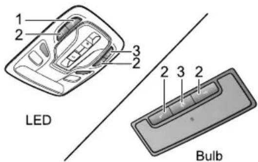
According to different configurations of the vehicles, the front interior lamp may feature bulbar LED configurations.
text_image
1 2 3 2 LED 2 3 2 BulbI MainManualControlSwitchofFront/RearInterior Lamps
2ManualControlButtonofCorrespondingFront InteriorLamp
3AutomaticControlButton
Presstheswitch I toturnonthefrontandrearinterior lamps, pressagaintoturnoff.
Presseitherofthebuttons2toturnonacorresponding frontinteriorlamp,pressagaintoturnoff.
Inadditiontotheabovemanualcontrolofinteriorlamps, in someconditionsthevehiclefeaturesanautomaticcontrol function.Pressthebutton3toturnonautomaticcontrol, pressagaintoreleasethebutton,andturnofftheautomatic function.
Whentheautomaticcontrolfunctionisenabled, thefront andrearinteriorlampsilluminateautomaticallyifanyofthe followingactionsarecarriedout:
•Thecarisunlocked.
•Anydoorisopened.
- Whenthevehiclelightsensordetectsthattheambient lightlevelisloworthesidelightshavebeenilluminated within30seconds,theinteriorlightwilloperatewhen theSTART/STOPSwitchissettoOFF.
Note: If a door is open for more than 15 minutes, the interior lamp will be switched off automatically to avoid battery drain.
INSTRUMENTSANDCONTROLS
RearInteriorLamp \*
natural_image
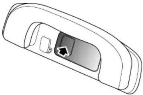
Diagram of a car interior showing a door, vent, and door handle with an arrow indicating direction (no text or symbols)VehiclesequippedwithLEDfrontinteriorlampare equippedwithLEDrearinteriorlamps.
Therearcourtesylightsarelocatedontheleftandright sidesofinteriorroofpanel.Pressthelamplensasindicated inthediagramtoswitchontherearcourtesylights,press itagaintoswitchoffthelights.
AmbientLamps \*
A
B
C
natural_image
Interior view of a car dashboard and steering wheel (no text or symbols visible)Ambientlampsarefittedoncertainmodelstocreatea comfortableatmosphereinsidethecar. The control of the ambient lampscan besetintheinfotainmentsystem. Ambient lamps are provided on the frontdoor interior trim panel (A), reardoor interior trim panel (B) and fasciapanel (C).
INSTRUMENTSANDCONTROLS
PowerSocket

Pleaseensurethesocketlidisinsertedwhen the 12Vpowersocketisnotinuse. This willensurenodebrisorforeignobjectssenter thesocketpreventingitsuseorcauseshort circuits.

The voltage of the 12V powersocket is 12 volt, and the power rating is 120 watt, please DONOT us the electrical appliance with its power exceeding therating.

Extendeduseoftheaccessorypowersocket andUSBsocketwhentheengineisswitched offwillcauseprematuredischargingofthe vehiclebattery.
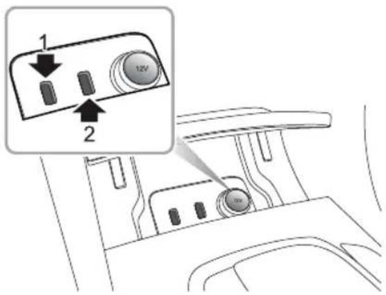
text_image
1 2 12VThe 12Vfrontpowersocketislocatedinthefrontofthe centreconsole.WhentheSTART/STOPSwitchisinthe ACC/ON/RUNNINGposition,removethesocketlid,it canthenbeusedasapowersupply.
TherearetwoUSBports(1and2)locatedattheleftside of 12Vfrontpowersocket,theUSBportscanprovide5V voltagewhenservingasthepoweroutlet,andcanbeused fordatatransmission.
INSTRUMENTSANDCONTROLS
TherearealsotwoUSBportslocatedattherearofthe centreconsole,theseprovide5Vvoltagewhenservingas thepoweroutlet.
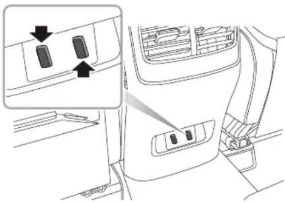
natural_image
Interior view of a car showing the dashboard and side panel with two buttons, no text or symbols present.Note:Nocigarettelighterisavailableonthevehicle. Ifrequired,pleaseseekanMGAuthorisedRepairer.
INSTRUMENTSANDCONTROLS
StorageDevices
Instructions
- Pleasecloseallstoragedeviceswhenthecarisin motion.Leavingthesstoragedevicesopenmay causepersonalinjuriesincasesofasuddenstart-off, emergencybrakingandacaraccident.
- Donotplaceflammablematerialssuchasliquidor lightersinanystoragedevices. Thetemperatureinhot conditionsmayigniteflammablematerialsandleadto afire.
GloveBox
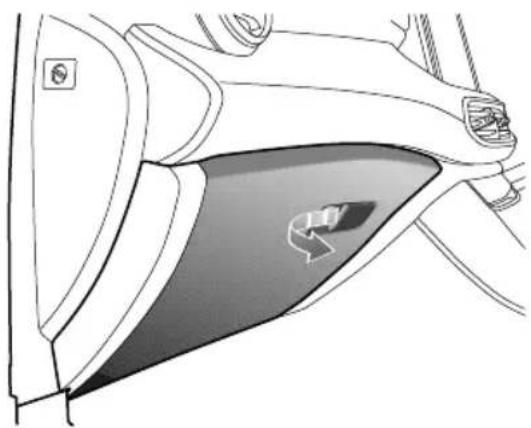
natural_image
Diagram of a car interior showing the side of the window with a highlighted car component (no text or symbols)T oopentheglovebox, pullthehandleontheglovebox cover(asindicatedbythearrow). Thegloveboxlightwill automaticallyilluminate.
Pushthelidforwardtoclosetheglovebox.Makesurethe gloveboxisfullyclosedwhenthecarisdriving.
INSTRUMENTSANDCONTROLS
StorageBox-DriverSide
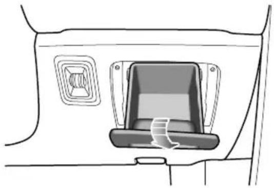
natural_image
Diagram of a car interior showing a seatbelt with a directional arrow indicating rotation (no text or symbols)Locatedbeneaththeinstrumentpanelonthedriverside, pullthestorageboxliddowntoopenthebox.
CentreConsoleArmrestBox
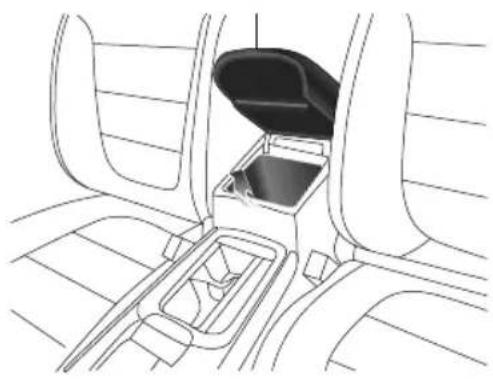
natural_image
Line drawing of a car interior showing the trunk, dashboard, and central trash bin (no text or symbols)Liftthearmrest(arrowed)toopenthecompartmentcover. Putthecoverdowntocloseit.
INSTRUMENTSANDCONTROLS
LoadSpaceCompartment

DONOTplacearticlesontheluggagecover * ,theycouldmovecausingpersonalinjuryin theeventofanaccident,emergencybraking orhardacceleration.
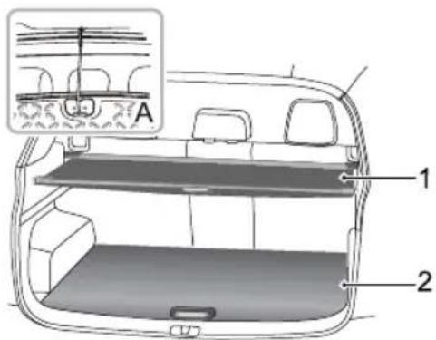
text_image
A 1 2If you plantousetheloadspace storage compartment, firstly retract the luggage cover * (1), move it along the groove until it is fully retracted.
Lifttheloadspacecarpet(2),fixitinplacetotheroof(A) withtheattachedhook.Placeitemssafelyintheloadspace storagecompartmentaccordingtotheirsizes.Afteritems areplaced,lowertheloadspacecarpet,ensuringitis locatedcorrectly.
INSTRUMENTSANDCONTROLS
CupHolder
Donotplacehotdrinksinthecupholder whilstdriving. Spillagemayresultinpersonal injuryordamage.
CentreConsoleCupHolder
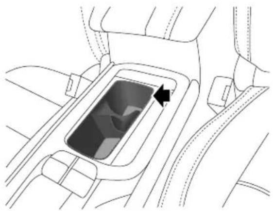
natural_image
Top-down line drawing of a car interior showing the dashboard and steering wheel (no text or symbols)Thecentreconsolecupholderissituatedatthefrontend of thecentreconsolearmrestassembly, and is used to hold acuporbeveragebottle.
RearArmrestandRearCupHolder
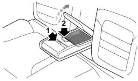
text_image
Diagram showing car seatbelt mechanism with labeled parts 1 and 2, indicating directional movement or positioning.Foldforwardtoopenthereararmrest.Pressbutton1 to openthecupholder .Pressbutton2toopenthestorage boxintherearofthearmrest.
INSTRUMENTSANDCONTROLS
RoofLuggageRack \*

RoofloadsMUSTNOTexceedthemaximum authorisedload. Thismayleadtoinjuryor vehicledamage.

Looseorimproperlyfixedloadsmayfallfrom theroofluggagerackandleadtoanaccident orcauseinjury.

When heavy or large items are carried on the offluggagerackit may lead to changes in steering, handling and braking characteristics. Please avoid sharp maneuvers, heavy braking and excessive acceleration.
Payattentiontothefollowingwhenusingtheroofluggage rack:
- Fixloadstowardsthefrontoftheroofasfaraspossible, anddistributetheroofloadevenly.
- DONOTuseautomaticcarwasheswithloadsontheroofluggagerack.
• The overall height of the car is different when loads are fitted to other of fluggagerack. Please ensure there is adequate clearance when entering tunnels and garages.
- Ensuretheloadscarriedbytheroofluggagerackdo notimpedeoperationofthesunroof,roofantennaof tailgateopening.
- When installing or removing a piece of loading equipment, follow instruction provided by the manufacture of loading equipment.
MaximumAuthorisedLoadfortheRoof
Themaximumauthorisedloadfortheroofis50kg,and theroofloadincludestheweightoftheroofloadsandthat ofthloadingequipmentinstalled.
Besuretoknowabouttheweightofloads,andweighthem whennecessaryNeverexceedthemaximumauthorised loadfortheroof.
PeriodicalCheck
Alwaycheck the condition of bol connectors and fasteners before using a rack luggage and periodically check the condition of bol connectors and fasteners.
AirConditioningandAudio Systems
72Ventilation
75ElectronicTemperatureControl *
80 AutomaticTemperatureControl *
86InfotainmentSystem
AIRCONDITIONINGANDAUDIOSYSTEMS
Ventilation
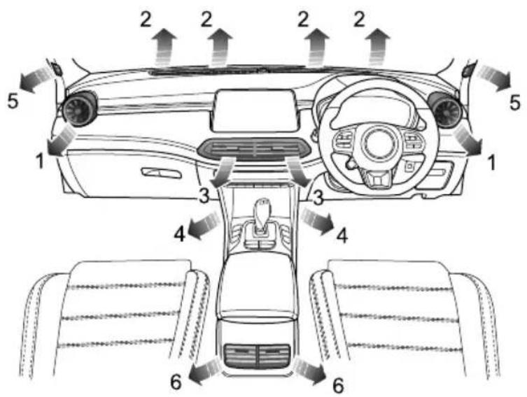
text_image
2 2 2 2 5 1 3 4 6 6 3 4 1 5I SideVents
2Windscreen/DefrostVents
3CentreVent
4FrontFootwellV ents
5FrontSideWindowV ents
6CentreConsoleVents
Therearealso2rearfootwellvents, respectivelyonthefloorunderthe frontseats(notshowninthefigure).
AIRCONDITIONINGANDAUDIOSYSTEMS
Theheating,ventilationandairconditioningsystem providesfresh,coolingorheatedairtotheinteriorofthe car.Freshairisdrawninthroughtheairintakegrilleunder thefrontwindscreenandtheairconditioningfilter.
Alwayskeeptheairintakegrilleclearofobstructionssuch asleaves,snoworice.
A/CParticle/PollenFilter
Theparticle/pollenfilterhelpstokeepthecarinteriorfree frompollenanddust.T oremainfullyeffective,thefilter shouldbereplacedattherecommendedserviceinterval.
Vents
CentreVents
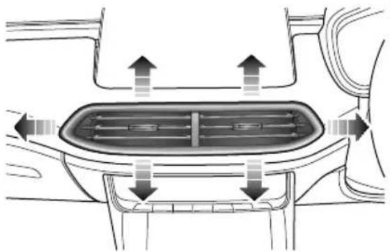
natural_image
Diagram of a car interior showing airflow or traffic flow around a vehicle intake tray (no text or symbols)Slidethebuttoninthecentreofthelouvrescompletely totheleftorrighttoopenorclosethevent,adjustthis buttonodirecttheflowofair.
T ogglethebuttonatthecentreofeachventupanddown, leftandrighttoregulatetheairdirection.
AIRCONDITIONINGANDAUDIOSYSTEMS
SideVents
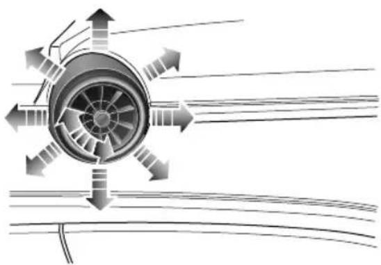
natural_image
Diagram of airflow around a turbine or fan blade, showing directional arrows and concentric blades (no text or labels)Rotatethecentrethumb-wheelclockwiseor anti-clockwisetoopenorclosethevent. T ogglethe centrethumb-wheelup, down, leftorrighttoadjustthe airdirection.
CentreConsoleVents
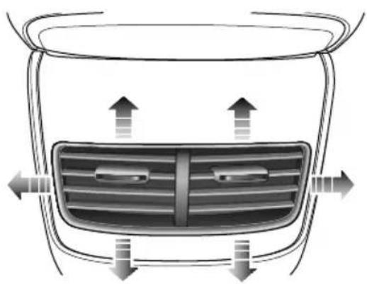
natural_image
Top-down view of a car's front grille with airflow arrows indicating direction (no text or symbols)Slidethebuttoninthecentreofthelouvrescompletely totheleftorrighttoopenorclosethevent,adjustthis buttontodirecttheflowofair.
T ogglethebuttonatthecentreofeachventupanddown, leftandrighttoregulatetheairdirection.
AIRCONDITIONINGANDAUDIOSYSTEMS
ElectronicT emperatureControl\*
InfotainmentScreenControlInterface
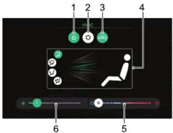
text_image
1 2 3 HVAC 4 6 5I SystemOn/Off
2ACCoolingOn/Off
3AirRecirculationMode
4AirDistributionMode
5T emperatureControl
6BlowerSpeedControl
AIRCONDITIONINGANDAUDIOSYSTEMS
SystemOn/Off
T ouchtheSystemOn/OffButtononthecontrolinterface toswitchthesystemon,allfunctionswillreverttothe statebeforeshutdown.T ouchagaintoswitchoff.
Note: Turningofftheinfotainmentscreenwillnot affecttheoperationoftheACsystem
ACCoolingOn/Off
T ouchtheACCoolingOn/OffT ouchButtontoturnthe ACcoolingfunctionON/OFF .
Note:
I Thecooling/heatingmodeoftheairconditioning willonlyoperatewhentheengineisrunning.
2Theheatingfunctionisstillavailable,whentheAC coolingisswitchedoff.
3A smallamountofwatermayremaininthe airconditionerafterusage, this may produce a peculiarsmell. If this is a particular issue, it is recommended to switch the cooling function
andruntheblowerforawhilewiththeengine runningpriortoswitchingoff.
AirRecirculationMode
Touchtherecirculationbuttononthecontrolinterfaceto operatetheairrecirculationfunction,theimagedisplayed intheswitchwillchangetodisplayyourchosenposition (externalorinternalcirculation),iftheairintakeisclosed theairinsidethecarisrecirculated,preventingtheentry oftrafficfumes.
Recirculationmodeisautomaticallyactivatedwhenthe screenwashersareusedorreversing.
Note:Leavingthesysteminrecirculationmodecan causethewindscreentomist. If this happens, switch offrecirculation and turn the control to maximum demisting.
AirDistributionMode
Select the corresponding Air Distribution Mode Touch Button as required to regulate the air distribution mode.
AIRCONDITIONINGANDAUDIOSYSTEMS
| T ouch Button | IconsonInterface | AirDistribution Mode |
 |  | T o‘face’ |
 |  | T o‘face’and‘feet’ |
 |  | T o‘feet’ |
 |  | T o‘feet’+‘windscreen’ |
T o'face'.Directsairtotheside,centreandcentreconsole vents.
T o'face'and'feet'.Directsairtothefootwell,side,centre andcentreconsolevents.
T o'feet'.Directsairtothefootwellvents.
Note: In this mode, as small amount of airflow will be directed to the beside, front sidewindow and windscreen/defrost Vents.
T o'feet'+'windscreen'.Directsairtothefootwell, windscreen/defrostandfrontsidewindowvents.
Note: In this mode, asmall amount of airflow will be directed to the beside events.
BlowerSpeedControl
Slidetheblowerspeedsegmentsleftorrighttoregulate theblowerspeed,thelowestpositionis1.
Touchblowerspeedsegmentquicklythe requiredblowerspeed.
T emperatureControl
Slidethetemperaturesegmentleftorrighttoregulate the temperatureoftheairsuppliedbythevents.
Touch the temperature segment to quickly set there required temperature.
AIRCONDITIONINGANDAUDIOSYSTEMS
ControlPanel
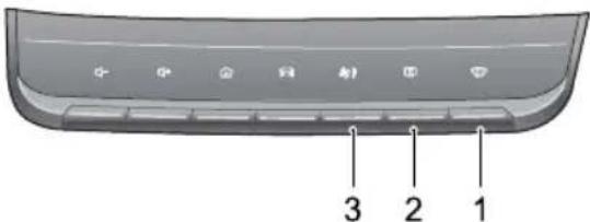
text_image
3 2 1IDefrost/DemistButton
2HeatedRearWindowButton
3A/CControlShortcut
Defrost/Demist

PressDefrost/DemistButtononthecontrol panelorthetouchbuttononthedisplay,theindicators onthebuttonanddisplayilluminate,theACcoolingand externalcirculationfunctionsareswitchedon,andthe systementersthemosteeffectivewarmorcoldairsetting toclearthewindshieldandsidewindow.
PressingtheDefrost/DemistButtonorthetouchbutton onthedisplayagainwillexitthedefrost/demiststate, theindicatorgoesout,andthesystemwillreturntothe previousstate.
Inthedefrost/demistmode, operationoftheACcooling on/offbuttonwillswitchthecompressoronoroff; operationoftheaircirculationmodebuttonwillswitch betweeninternalcirculationandexternalcirculation, withoutaffectingthedefrost/demistmodeineithercase; operationofotherairdistributionmodeswillswitch toacorrespondingairdistributionmodeandquitthe defrost/demistmode.
Note: Whenthedefrost/demistfunctionisswitched onbelowapresettemperature,theheatedrear windowfunctionwillautomaticallyoperatthe Defrost/Demistbuttonandtheheatedrearwindow buttonindicatorlightswillilluminatesimultaneously.
AIRCONDITIONINGANDAUDIOSYSTEMS
HeatedRearWindow

Theheatingelementsontheinsideoftherear windowareeasilydamaged.DONOTscrape orscratchtheinsideoftheglass.DONOT sticklabelsovertheheatingelements.
Pressthisbuttononthecontrolpanelto operatetheheatedrearwindowfunction,theindicator intheswitchwillilluminate.Theheatedrearwindow functionwillautomaticallyturnoffafteroperatingfor15 minutes.Iftheswitchispressedagainwithin5minutes, theheatedrearwindowwilloperateandthenremainon forafurther8minutes.Pressingtheswitchwhilstthe heatedrearwindowisonwillswitchchoffthefunctionand extinguishtheindicatorintheswitch.
Note: The heated rear window will only operate when the engine is running.
Note: Heateddoormirrorsonlyoperatewhenthe heatedrearwindowisactivated.
A/CDisplay
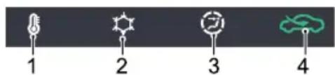
text_image
1 2 3 4ITemperatureStatus
2ACCoolingStatus
3BlowerSpeed/AirDistributionModeStatus :
For'face
For 'face and 'feet'
For'feet
• For'feet'and'windscreen' windscreen'
4AirRecirculationModeStatus :
• Internalcirculation
Externalci-cation
AIRCONDITIONINGANDAUDIOSYSTEMS
AutomaticT emperatureControl
InfotainmentScreenControllInterface

text_image
1 2 3 4 5 HVAC AUTO 17°C 16°C LO 2 8 7 6 SYNC 17°C 16°C LO 9AiDistributionMode
SystemOn/Off
AutoMode
ACCoolingOn/Off
AirCirculationMode
HighZone Temperature Control
TemperatureZoneControl
HoweSpeedControl
LeftZoneTemperatureControl
AIRCONDITIONINGANDAUDIOSYSTEMS
SystemOn/Off
T ouchtheSystemOn/OffButtononthecontrolinterface toswitchthesystemon,allfunctionswillreverttothe statebeforeshutdown.T ouchagaintoswitchoff.
Note: Turningofftheinfotainmentscreenwillnot affecttheoperationoftheACsystem
ACCoolingOn/Off
T ouchtheACCoolingOn/OffT ouchButtontoturnthe ACcoolingfunctionON/OFF.
Note:
I Thecooling/heatingmodeoftheairconditioning willonlyoperatewhentheengineisrunning.
2Theheatingfunctionisstillavailable,whentheAC coolingisswitchedoff.
3A smallamountofwatermayremaininthe airconditionerafterusage, this may produce a peculiarsmell. If this is a particular issue, it is recommended to switch the cooling function
andruntheblowerforawhilewiththeengine runningpriortoswitchingoff.
AirCirculationMode
Touchtherecirculationbuttononthecontrolinterfaceto operatetheairrecirculationfunction,theimagedisplayed intheswitchwillchangetodisplayyourchosenposition (externalorinternalcirculation),iftheairintakeisclosed theairinsidethecarisrecirculated,preventingtheentry oftrafficfumes.
Recirculationmodeisautomaticallyactivatedwhenthe screenwashersareusedorreversing.
Note:Leavingthesysteminrecirculationmodecan causethewindscreentomist.Ifthishappens,switch offrecirculationandturnthecontrolstomaximum demisting.
AutoMode
Adjust the temperature on the infotainment screen control interface, set the target temperature required and then
AIRCONDITIONINGANDAUDIOSYSTEMS
presstheAUTOOn/Offbuttontoenabletheautocontrol function.
Intheautomode, theairdistributionmode and theblower speed area automatically adjusted to each and maintain the required temperature.
Note: To ensure the autocontrol operates efficiently, all windows and the sunroof must be closed and the A/Cinlet grillem must be clear of obstruction. In addition, the solar sensor on the upper part of the instrument panel should not be recovered.
ManualMode
Theairdistributionmodeandblowerspeedcanbe adjustedmanuallyaccordingtopersonalpreference.In thiscasetheAUTOindicatorwillextinguish.
AirDistributionMode
Select the corresponding Air Distribution Mode Touch Button as required to regulate the air distribution mode.
| T ouch Button | IconsonInterface | AirDistribution Mode |
 |  | T o‘face’ |
 |  | T o‘face’and‘feet’ |
 |  | T o‘feet’ |
 | T o‘feet’+‘windscreen’ |
T o'face'.Directsairtotheside,centreandcentreconsole vents.
T o'face'and'feet'.Directsairtothefootwell,side,centre andcentreconsolevents.
T o'feet'.Directsairtothefootwellvents.
Note: In this mode, as small amount airflow will be directed to the side, front sidewindow and wind screen/defrost Vents.
AIRCONDITIONINGANDAUDIOSYSTEMS
T o'feet' + 'windscreen'. Directsairtothefootwell, windscreen/defrostandfrontsidewindowvents.
Note: In this mode, as small amount of airflow will be directed to the beside events.
T emperatureZonecontrol
T ouchthetemperaturezonecontrolbuttontoswitch thesystembetweensingleordualtemperaturezone control. Whenthebuttonisilluminatedbothzonesare synchronised.
BlowerSpeedControl
Slidetheblowerspeedsegmentsleftorrighttoregulate theblowerspeed,thelowestpositionis I.
Touchtheblowerspeedsegmenttoquicklysetthe requiredblowerspeed.
T emperatureControl
Slidethetemperatureupordowntoregulate the temperatureoftheairsuppliedbythevents.
ControlPanel
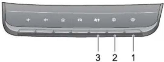
2HeatedRearWindowButton
3A/CControlShortcut
Defrost/Demist

PressDefrost/DemistButtononthecontrol panelorthetouchbuttononthedisplay,theindicators onthebuttonanddisplayilluminate,theACcoolingand externalcirculationfunctionsareswitchedon,andthe systementersthemosteffectivewarmorcoldairsetting toclearthewindshieldandsidewindow.
AIRCONDITIONINGANDAUDIOSYSTEMS
PressingtheDefrost/DemistButtonorthetouchbutton onthedisplayagainwillexitthedefrost/demiststate, theindicatorgoesout,andthesystemwillreturntothe previousstate.
Inthedefrost/demistmode, operationoftheACcooling on/offbuttonwillswitchthecompressoronoroff; operationoftheaircirculationmodebuttonwillswitch betweeninternalcirculationandexternalcirculation, withoutaffectingthedefrost/demistmodeineithercase; operationofotherairdistributionmodeswillswitch toacorrespondingairdistributionmodeandquitthe defrost/demistmode.
Note: Whenthedefrost/demistfunctionisswitched onbelowapresettemperature,theheatedrear windowfunctionwillautomaticallyoperate,the Defrost/Demistbuttonandtheheatedrearwindow buttonindicatorlightswillilluminatesimultaneously. Turnonoroffthisfunction,pleaseoperatein'Vehicle Settings-HVAC'.
HeatedRearWindow

Theheatingelementsontheinsideoftherear windowareeasilydamaged.DONOTscrape orscratchtheinsideoftheglass.DONOT sticklabelsovertheheatingelements.
Pressthisbuttononthecontrolpanelto heatedrearwindowfunction,theindicator willilluminate.Theheatedrearwindow automaticallyturnoffafteroperatingfor15heswitchispressedagainwithin5minutes, rearwindowwilloperateandthenremainon 8minutesBressingtheswitchwhilstthe windowisonwillswitchoffthefunctionand theindicatorintheswitch.
Note: The heated rear window will only operate when the engine is running.
Note: Heateddoormirrorsonlyoperatewhenthe heatedrearwindowisactivated.
AIRCONDITIONINGANDAUDIOSYSTEMS
A/CStatus
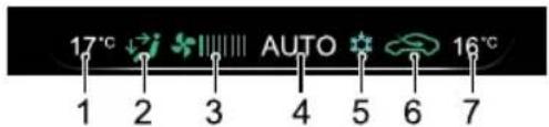
text_image
17°C AUTO 16°C 1 2 3 4 5 6 77RightZoneT emperatureStatus
ILeftZoneT emperatureStatus
2AirDistributionModeStatus :
- For'face'
•For 'ace' and 'feet'
•For feet'
• For'feet'and'windscreen'
•Forvindscreen' - Automode
3BlowerSpeedStatus
4AutoModeStatus
5ACCoolingStatus
6AirRecirculationModeStatus :
•Intercirculation
• Externalcirculation
AIRCONDITIONINGANDAUDIOSYSTEMS
InfotainmentSystem
ImportantSafetyInformation
- Donotattempttofit, repairormodify the entertainmentsystembyyourself, because there are high-voltage components in the device, which may cause electric shock. For internal inspection, adjustment or repair, please consult a local MG Authorised Repairer.
- Donotallowthisentertainmentandnavigation systemtocomeintocontactwithliquidliquids orforeignobjectsenteintothisentertainmentand navigationsystem,pleaseparkyourvehicleatasafe place,immediatelyswitchofftheignitionandcontact alocalMGAuthorisedRepairDonotusethe entertainmentandnavigationsysteminthiscondition because doing may result in fireelectricshockor otherfailure.
• If you notices smoke, abnormal noises or odours from the entertainmentsystem any other abnormalities on the screen, switch the ignition off immediately and contact a local MAuthorised Repaire for service.
Using this entertainment system in this condition may result in permanent damage of the system.
• Operationofthenavigationorvideofunctionsothe systemprohibitedwhilethevehiclimation. MGMotorUKacceptsnoresponsibilityforany consequencescausedbythisoperation.Pleasepark yourvehicleinasafelocationselectPark/Neutral,and applyhparkingrakbeformakingthenecessary adjustmentsorwatching"Video".
•Particular high or particularly low temperatures will interfere with normal operation. If the vehicle is not used and parked directly in cold location for long time, may be completely hot, in this environment the system may not work properly. Once the temperature inside the air back to normal, the system will resumenormal function. If it does not resume please contact MGA authorised Repaire for assistance.
- Switchoffentertainmentandnavigationsystemduring refuelling.
AIRCONDITIONINGANDAUDIOSYSTEMS
- Excessive use of the entertainment and navigation system without the vehicle being driven by engine running and rain the vehicle low voltage battery.
- If the battery is disconnected, discharged, the data stored in the memory of this entertainment and navigation system will be erased.
- When using a mobile phone, keep the antenna of the mobile phone away from the screentoprevent the disruption of videosignalin the form of spots, colored stripes, etc. on the screen.
- T oprotectthescreenagainstdamage,besuretotouch thepanelbuttonswithyourfinger(atouchpencanbe usedforspecialcalibration).
- Thenavigationsystemisdesignedonlyasaguideand doesnotrelievethedriveroftheresponsibilityfor drivinginaccordancewithtrafficregulations.
CautionsforUsingScreen
- T oprotectthescreenagainstdamage, alwaystouch panelkeyswithyourfinger. Atouchpenmaybeused for special calibration.
- Please take care to protect the screen again at direct sunlight. Extended exposure to direct sunlight will result in screen malfunction due to high temperature.
- Whenthetemperatureisbeyondtheoperating temperaturerange(-30°Cto+85°C), pleasedonot usethescreen, because the screen may not operate normally and could bedamaged.
- Donotuseexcessiveforcetodraganddroporpress thescreen,damageorscratchingmayoccur .
•T oremovedustfromthescreenorcleanthescreen, poweroffthesystemfirst,thenwipethescreenwitha drysoftcloth.Whenwipingthescreen,takecarenot toscratchthesurface.Donotuseirritativeorabrasive chemicalcleaners.
• Makesurethatthewarmorcoolairflowfromtheair conditionerisnotdistributeddirectlyontothescreen, damagetotheentertainmentdevicemayoccurdueto excessiveheatormoisture. - Whenthebacklightreachestheendofitsservicelife, thescreenwillbecomedimmerandtheimagewillno longerbevisible,pleasecontactalocalMGAuthorised Repairer.
AIRCONDITIONINGANDAUDIOSYSTEMS
AdditionalNotes
- Sometypesofexternalstoragedevicesmaynotbe recognised. This may result in the files not being played or displayed normally.
- Becauseoffilecharacteristics,fileformat,recorded application,playbackenvironment,storageconditions andotherfactors,itmaynotbepossibletoplaythe filesnormally.
BasicOperations
ControlPanel
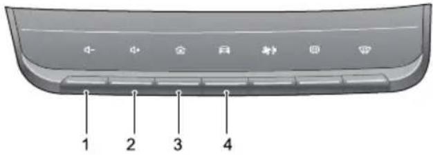
text_image
1 2 3 4IVolumeDownButton
Presstolowerthevolume.
2VolumeUpButton
Presstoincreasethevolume.
3(HOME)Button
Shortpresstoreturntothemaininterface.
4VehicleSettingButton
Shortpresstoenterthevehiclesettingsinterface.
AIRCONDITIONINGANDAUDIOSYSTEMS
MainSystemInterface
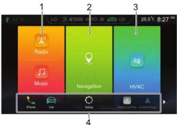
text_image
1 2 3 25.0°C 8:27 AM Radio Music Navigation HVAC Phone Car Setup Apple Play Added AutoIRadio/Music
TouchtoentertheRadio/Musicinterface.
2Navigation
TouchtoentertheNavigationinterface.
3HVAC
Touchtoentertheheating,ventilationandAC interface.
4Others
Touchers pelettorrightatthebottomof thescreentoviewthefollowingfunctions.
•Phone
TouchtoentertheBluetoothPhoneinterface.
Car
Touch toentertheVehicleSettingsinterface.
- Setup
T ouch toentertheSettingsinterface.
•AppleCarplay
TouchtoentertheAppleCarplayinterface.
-AndroidAuto
Touch toentertheAndroidAutointerface.
•Pictures
T ouch toenterthePicturesinterface.
•Video
AIRCONDITIONINGANDAUDIOSYSTEMS
TouchtoentertheVideointerface.
•DisplayOff
T ouchtoturnoffthedisplay;touchagaintowake upthedisplay.
PowerOn/Off
PowerOn
If the vehicle power is turned off with the system currently in playback mode, the system will be automatically powered on when the vehicle power is turned on again.
If the vehicle power is turned off with the system in the Off state, short press the Power button on the system control panel top power-on the system after the vehicle power is turned on again.
With the system on long press the HOME button on the system control panel to enter the Standbymode; keep pressing the button and the system will reboot automatically.
PowerOff
PressingtheStart/StopbuttontotheOffpositionwill automaticallyswitchoffthelnfotainmentsystem.
AIRCONDITIONINGANDAUDIOSYSTEMS
StandbyMode
WiththeStart/Stopswitchon,longpresstheHOME buttontoallowthelnfotainmentsystemtoenterthe Standbymode,theoperationofthelnfotainmentsystem maybesuspended.
InStandbymode, allsoundswillbemuted. T ocancelthe Standbymode, shortpress the HOMEbutton.
The following operations can also cancel the Standbymode:
- Thesystemautomaticallyswitchestotheparkingimage duringparking.
- T urnofftheStart/Stopswitch,thesystemshutsdown directly.
ControlButtonsonSteeringWheel
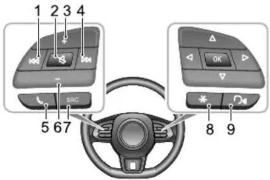
text_image
1 2 3 4 SRC 5 67 8 9Button
Whenplayingaudio,shortpresstoreturntothe beginningtherack(excepthBluetoothmusic mode),shortpressagaintoswitchtoprevioustrack, andlongpresstorewind(excepttheBluetoothmusic mode)heplayingideashopresstowitch topreviousvideo,andlongpresstorewindWhen playingradio,shortpresstoautomaticallysearchfor
AIRCONDITIONINGANDAUDIOSYSTEMS
thepreviousstation;longpresstomanuallysearchfor thepreviousstation.
2Button
Mute/Unmute.
3VolumeUpButton
4Button
Whenplayinganaudio/video,shortpresstoswitch tonexttrack/video(excepttheBluetoothmusic mode),andlongpresstofastforward.Whenplaying radio,shortpresstoautomaticallysearchforthenext station;longpresstomanuallysearchforthenext station.
5Button
Shortpresstohangupifincalling/talkingstate;short presstoanswerandlongpresstorejectifinincoming callstate.
6VolumeDownButton
7SRCAudioSourceSwitchButton
Switchtothenextavailablemediaaudiosource.
8“*”ButtononSteeringWheel
"*"buttononthesteeringwheelcanbesetasthe shortcutkeyofSmartPhone/Home/Car .
9SpeechRecognitionFunctionButton
Activate/ Cancelspeech recognition function this buttonwillonlybeusedafterV vehicle-MobilePhone Interconnection * isenabled.
AIRCONDITIONINGANDAUDIOSYSTEMS
VolumeAdjustment
Theaudiovolumecanbeadjustedbythecontrolpanel andthebuttonsonthesteeringwheel.Duringthevolume adjustment,thesystemautomaticallypopsupavolume indicationwindowwhichchangessmoothlywiththe adjustmentprocess.
Note: The volume button on the steering wheel and control panel can only be used for the volume adjustment of audiosof media and communication type.
Note: The playback volume of Bluetooth music can be adjusted by the device itself and the Infotainment player.
Connecting/DisconnectingaUSBStorage
Device
InsertingaUSBStorageDevice
ConnectaUSBdevicetotheUSBportforconnection.
RemovingaUSBStorageDevice
Checkandconfirmthatthereisnodatabeingaccessed, thenpullouttheUSBstoragedevice.
Note: If datalossordamagetothestoragedevice occurs for any reason, the data will generally never berecovered. Fordamages, costsorexpenses dueto datalossordamage, themanufacturerassumes no responsibility.
Note: Some USBstoragedevices maybe unidentifiable.
Note: The Infotainmentsystemmaynotachieveits optimumperformancewhenusingwithsomeUSB storagedevices.
AIRCONDITIONINGANDAUDIOSYSTEMS
Note: Using USB huborextensioncablemaynot identifyUSBdevice.
BluetoothPhone
Instructions
- ConnectiontoallmobilephonesfeaturingBluetooth wirelessstechnologyisnotguaranteed.
- Themobilephoneusedmustbecpatiblewiththe InfotainmentsystemsothatallfunctionsofBluetooth phoneofthesystemcanfunctioncorrectly
- WhenusingBluetoothwirelesstechnology,the Infotainmentsystemmaynotoperateallfunctionson themobilephone.
- WhentransmittingvoiceanddataviaBluetooth technology,thestraight-linedistancebetweenthe Infotainmentsystemandthemobilephoneshouldnot exceed10metres.However,theactualtransmission distancemaybebeshorterthantheestimateddistance, dependingontheusageenvironment.
- IfPrivatemodeisselectedonthemobilephone, hands-freecallfunctionwillbedisabled.
- Whenthelnfotainmentsystemisturnedoff, the Bluetoothconnectionwillbedisconnected.
AIRCONDITIONINGANDAUDIOSYSTEMS
- DuetoBluetoothwirelessconnection, interruptionor erroroccurringintheprocessoftransmissioninsome extremecases, and the Infotainmentsystem maybe unable to be paired and connected with themobile phone. At this time, it is recommended to clear the paired devices in the device list on themobile phone and the Infotainmentsystem, and conduct pairing again.
BluetoothPairingandConnection
IfBluetoothisnotenabled,noBluetoothiconisdisplayed inthestatusbar;ifBluetoothisenabledbutnodeviceis connected, isdisplayedinthestatusbar;ifBluetoothis enabledandanydeviceisconnected,isdisplayedinthe statusbar.
ThestepsofBluetoothpairingandconnectionareas follows:
- T ouch[Bluetooth]intheSettingsinterfacetoenter theBluetoothconnectionsettingsinterface,andtouch
toenabletheBluetoothfunction.
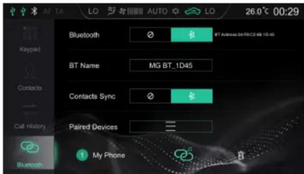
text_image
AE TA LO AUTO LO 26.0°C 00:29 Bluetooth BT Address: 56 PB/C2:48-1D-65 BT Name MG BT_1D45 Contacts Sync Paired Devices My PhoneAIRCONDITIONINGANDAUDIOSYSTEMS
- ThesystemdisplaytheBluetoothaddressandthe devicename.
- EnabletheBluetoothonthemobilephoneandsearch forthelnfotainmentsystemforpairing. Themobile phonewillreceiveaBluetoothPairingrequest,afterthe pairingiscompleted,apromptmessageofConnection Completedwillappear.Ifthepairingfails,pleaserepeat theabovesteps.
- Themobilephonesthathavebeensuccessfullypaired willbestoredinthelistofpaireddevices.T ouch toviewtheDeviceList.T ouchtoclecttothe mobilephoneBluetooth,andtouchodisconnect theBluetooth.T ouchtremovethemobilephone fromthelistofpaireddevices.

Keypad
Touch[Keypad]intheBluetoothPhoneinterfacetoenter theDialPadinterface.
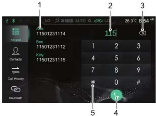
text_image
1 2 3 4 5 6 7 8 9 10 11 115 11501231114 11501231112 Ben 11501231115 Kitty 11501231115 Contacts Call History BluetoothI AddressList/PairedContacts
2InputBox
3Back/DeleteButton
4MakeaCall
AIRCONDITIONINGANDAUDIOSYSTEMS
Touchtomakeacall;whentheBluetoothphoneis connected,touchtoendthecall.
5InputKeypadArea
Input figures and symbols.
Contacts
Touch[Contacts]intheBluetoothPhoneinterfacetoenter theContactsinterface.
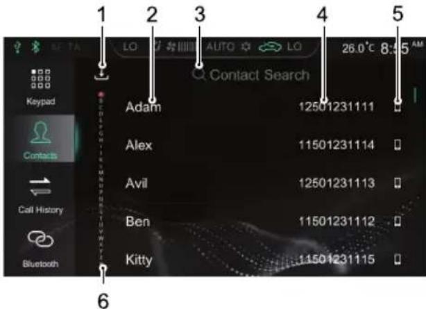
text_image
1 2 3 4 5 Contact Search LO AUTO LO 26.0°C 8:5 AM Adam 12501231111 Alex 11501231114 Avil 12501231113 Ben 11501231112 Kitty 11501231115 Keypad Contacts Call History Bluetooth 6I DownloadContacts
When connected to a mobile phone via Bluetooth the entertainments system default setting will automatically download your contacts. The Auto
AIRCONDITIONINGANDAUDIOSYSTEMS
ContactsDownloadfunctioncanbedisabledor enabledintheConnectionsSettingInterface.
ClickintheContactsinterfacetodownloadthe Contactsmanually.
2 ContactName
3SearchforaContact
Touch[ContactSearch]intheinterface, input the initial letter of thenametobesearched, after the search is completed, touch the contact to make a call.
4PhoneNumber
5PhoneType
Whenacontacthasmultiplephonenumbers,touch to switch the phonenumbertype and select the phonenumbertomakeacall.
6QuickContactSearch
T ouchtheletterontheleftoftheinterfaceorswipe thecreertoquicklylocatethecontactwiththisletter astheinitialletter.
Not Forsomemobilephones, adialogboxasking whethertodownloadBluetoothphonecontactswill popbefordownloadingBluetoothphone contacts.
Note: Sincethesystemtemporarilydoesnotsupport somecommerciallyavailablemobilephones, the case ofnosynchronisationofBluetoothphonebookwill occuronnonsupportedphones.
Not new contact that reddewilldte displayed until then next syncronisation is carried out.
AIRCONDITIONINGANDAUDIOSYSTEMS
CallHistory
Touch[CallHistory]intheBluetoothPhoneinterfaceto entertheCallHistoryinterface.
T ouchtherequiredcallhistoryrecordinthelisttocallthe contact.
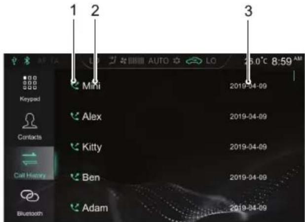
Y oumaymakeacallusingthefollowingmethods:
- KeypadInput:Referto "Keypad" in this section for details.
- CallthenumberinContacts:Referto"Contacts"in thissectionfordetails.
- CallthenumberinCallHistory:Referto"CallHistory" inthissectionfordetails.
• Makeacalldirectlyonthemobilephone.
EndaCall
Y oumayendacallusingthefollowingmethods:
•T ouch 📋 tohangup.
•Shortpress 📋 onthesteeringwheeltohangup.
• Hanguponthemobilephone.
Note: It is illegal to operate a mobile telephone whilst driving. If you wish to make, or take a call using your mobile phone directly, please ensure you pull over a suitable location and operate the mobile phone where it is safe and legal to do so.
IncomingCall
AnsweranIncomingCall
•T ouch 📞 toansweranincomingcall.
- Shortpress buttononthesteeringwheeltoanswer anincomingcall.
- Answeranincomingcallonthemobilephone.
RejectanIncomingCall
Note: It is illegal to operate mobile telephone whilst driving. If you wish to make, or take a call using your mobile phone directly, please ensure you pull over in suitable location and operate them mobile phone where it is safe and legal to do so.
AIRCONDITIONINGANDAUDIOSYSTEMS
SwitchtoPrivateMode
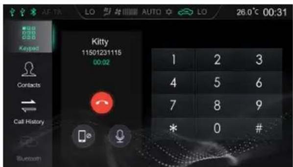
text_image
AF-TA LO AUTO LO 26.0°C 00:31 Keypad Kitty 11501231115 00:02 Contacts Call History Bluetooth 1 2 3 4 5 6 7 8 9 * 0 #Duringacall,touchtoenterthePrivateMode (SpeakerModebydefault).
Duringacall,touchtorestoretheSpeakerMode.
Duringacall,touchtoswitchbetweenMicrophone MuteorEnabledfunction.
InPrivateMode,youmaycontinuewiththecallusing themobilephone;thespeakersandmicrophoneofthe
Infotainmentsystemwillbemuted.ButBluetoothisstill connected.
Note: It is illegal to operate mobile telephone whilst driving. If you wish to make, or take call using your mobile phone directly, please ensure you pulloverina suitable location and operate them mobile phone where it is safe and legal todos.
AIRCONDITIONINGANDAUDIOSYSTEMS
Entertainment
PrecautionsforPlayingaStorageMediumMode
- ThesystemsupportsUSBdrivesandBluetoothstorage media.
- If the USB device media is not in use, DONOT leave the device connected. This may result in connection deterioration.
- DonotremoveUSBdevicewhilstmediaisplaying. Failuretofollowtheseinstructionscouldresultin corrupteddata.
- KeeptheUSBportdryandfreefromdebris. Theport willbecomeunusableifitisblocked.
Radio
TouchtheRadio/Musicareainthemaininterface, and touch[Radio]againtoentertheRadiointerface.
T olistentothebroadcastingofdifferentbands,touch [DAB] *,[FM]or[AM]intheplaybackinterfacetoswitch betweenDABandradiobands.PressingtheSRCbutton canalsoswitchbetweenthedifferentradriobands.
DAB*
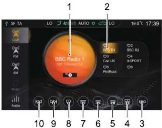
text_image
SF TA LO AUTO LO 19.0°C 17:39 1 2 BBC Radio 1 BBC Radio2 BRC R1 3 Cap UK 5 PrintRock 2 BBC R2 4 SPORT 6 Audio 10 9 8 7 6 5 4 3I CurrentStationNameorFrequency
Touch[DAB],[FM]or[AM]toswitchtheband.
2DisplayofFavoriteStations
3ElectronicProgramGuide
4DABCategoriesList
5Radioinformation
T ouchingthebuttonwilldisplayradioinformation, suchastext,picture.
AIRCONDITIONINGANDAUDIOSYSTEMS
6StationList
7ListofFavoriteStations
8AddaStationto/RemoveaStationfromFavorites
9NextStation
Shortpresstoautomaticallysearchforthenext station;longpresstomanuallysearchforthenext station.
10PreviousStation
Shortpresstoautomaticallysearchfortheprevious station;longpresstomanuallysearchfortheprevious station.
FM/AM
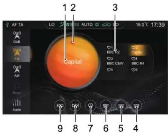
text_image
AF TA LO AUTO LO 19.0°C 17:39 1 2 3 Capital ♥1 BBCTR2 ♥2 Capital ♥3 BBC C&W ♥4 BBC R4 ♥5 ♥6 9 8 7 6 5 4I CurrentStationNameorFrequency
Touch[DAB], [FM] or [AM] to switch the band.
2StationFavoritesState

indicatesthatthestationhasbeenaddedto
Favorites; indicates that the station is not added to favorites.
3DisplayofFavoriteStations
AIRCONDITIONINGANDAUDIOSYSTEMS
4Radiolnformation
T ouchingthebuttonwilldisplayradioinformation, suchastext,picture.
5StationList
6ListofFavoriteStations
7AddaStationto/RemoveaStationfromFavorites
8NextStation
Shortpresstoautomaticallysearchforthenext station;longpresstomanuallysearchforthenext station.
9PreviousStation
Shortpresstoautomaticallysearchfortheprevious station;longpresstomanuallysearchfortheprevious station.
Touch[Audio]inthisinterface,andthesystemskipstothe AudioSettingsinterface.
USBMusic
InsertaUSBstoragedeviceintotheUSBport,andthe systemautomaticallyloadsthemusicfromthestorage device.
TouchtheRadio/Musicareainthemaininterface,and touch[USBMusic]againtoentertheUSBMusicPlayback interface.
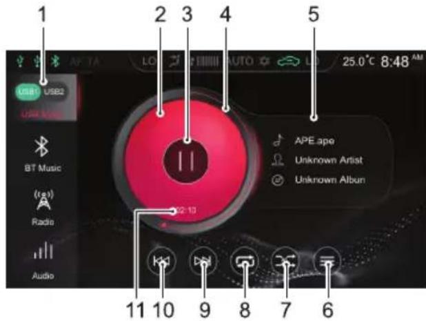
text_image
1 2 3 4 5 USB1 USB2 USB King BT Music Radio Audio 02-10 APE ape Unknown Artist Unknown Album 11 10 9 8 7 6AIRCONDITIONINGANDAUDIOSYSTEMS
IUSBDrive
WhentherearetwoUSBdrives,youmaychooseto playmusicinUSBI or USB2.
2AlbumCover
3Play/Pause
4T rackPlaybackProgressBar
T rack playback progress is displayed by the coil, drag the progress bartoskiptocertain playing point.
5Song/Artist/AlbumName
6USBMusicList
TouchtoenterthecorrespondingFolderListinterface, thentouchtoselectandplaythetrackyouprefer.
7RandomPlaybackMode
Y oumayswitchbetweenRandomPlaybackandFolder RandomPlayback.
8LoopPlaybackMode
Y oumayswitchbetweenSingleLoop, FolderLoopand LoopAll.
9NextT rack
Shortpresstoswitchtothenexttrack;longpressto fastforward.
10PreviousTrack
Shortpresstoswitchtotheprevioustrack;short pressduringplayingtoreturntothebeginningofthe track;longpresstofastrewind.
I I Current Elapsed Time
Touch[Audio]inthisinterface,andthesystemskipstothe AudioSettingsinterface.
AIRCONDITIONINGANDAUDIOSYSTEMS
BluetoothMusic
PleaseconnectaBluetoothdevicefirstbeforeplaying Bluetoothmusic. Referto "BluetoothPairing and Connection" in "BluetoothPhone" sectionfordetails.
AftertheBluetoothdeviceisconnectedwiththesystem, touchtheRadio/Musicareainthemaininterface,andthen touch[BTMusic]toentertheBluetoothMusic playback interface.
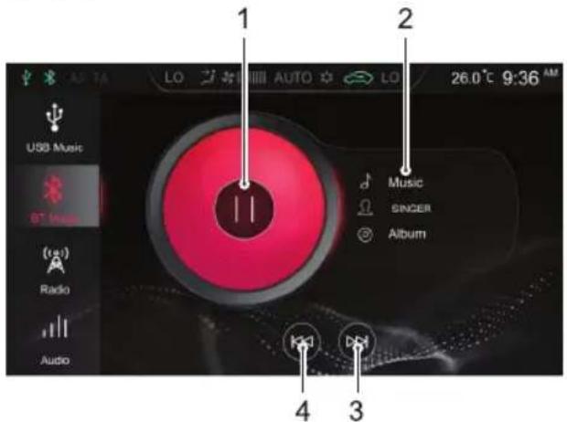
text_image
1 2 USB Music ST Music Audio Radio Audio Music SINGER Album 4 3 26.0°C 9:36 AMI Play/Pause
2Song/Artist/AlbumName
3NextT rack
4PreviousTrack
Touch[Audio]inthisinterface,andthesystemskipstothe AudioSettingsinterface.
AIRCONDITIONINGANDAUDIOSYSTEMS
USBVideo
InsertaUSBstoragedeviceintotheUSBport,andthe systemautomaticallyloadsthevideosfromthestorage device.
Note: Duetodifferencesinthecompressionratio and bitrateofthemultimediaformatsdownloadedfrom theInternetandotherfactors,theactualsituationof thedecodingresultshallprevail.
Note: Foryourdrivingsafety, when the vehicles speed reaches ascertain value, the videos safety modewill be activated automatically, the video cannot be played at that moment.
Note: The video cannot be played during acall.
Touch[Video]inthemaininterfacetoentertheVideo Playbackinterface.
Note: When playing a video, click the screentowake upthemenubarmode, and click itagainto exit the menubarmode.
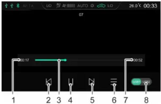
text_image
00:17 00:52 USB UWBI CurrentElapsedTime
2PreviousVideo
Shortpresstoswitchtothepreviousvideo;longpress tofastrewind.
3PlaybackProgressBar
Dragtheprogressbartoskiptocertainplayingpoint.
4Play/Pause
5NextVideo
AIRCONDITIONINGANDAUDIOSYSTEMS
Shortpresstoswitchtothenextvideo;longpressto fastforward.
6VideoList
Y oumayviewandplaythecorrespondingvideofile.
7T otalVideoDuration
8USBDrive
WhentherearetwoUSBdrives,youmaychooseto playvideosinUSB1 or USB2.
Pictures
InsertaUSBstoragedeviceintotheUSBport,andthe systemautomaticallyloadsthepicturesinthestorage device.
Touch[Pictures]inthemaininterfacetoenterthepicture Playbackinterface.
T ouchapicturefiletodisplayitinfullscreen.
Note: Whilstviewingapicturefile, clickthescreento wakeupthemenubarmode, and clickitagaintoexit themenubarmode.
AIRCONDITIONINGANDAUDIOSYSTEMS
PictureBrowsingInterface
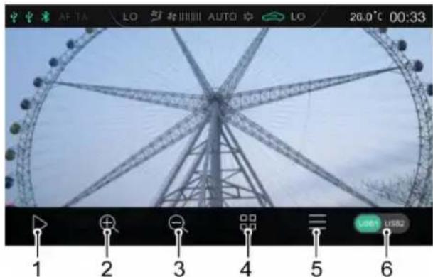
text_image
AF 7A LO AUTO LO 26.0°C 00:33 1 2 3 4 5 6 USB1 USB2ISlideShow
2ZoomIn
3ZoomOut
4Thumbnail
5PicturesList
Y oumayviewandplaythecorrespondingpicturefile.
6USBDrive
WhentherearetwoUSBdrives,youmaychooseto viewpicturesinUSBI orUSB2.
Note: Thesystemsupportstheviewingofpictures storedonaUSBdevice.Duetodifferencesinpicture resolution, formatcompressionratioandsomeother factorsnotallpicturesmaybedecodedanddisplayed.
Note: Swipetotheleftorrightonthescreentoswitch tothenextorpreviouspicture.
AIRCONDITIONINGANDAUDIOSYSTEMS
Vehicle-MobilePhoneInterconnection \*
OnlyapplicabletomodelsthatfeatureVehicle-Mobile PhoneInterconnection.
AppleCarPlay \*
AppleCarPlayenablesinformationinteractionbetween themobilephoneandtheon-boardInfotainmentsystem, includingmap,music,telephone,shortmessage,podcast, voicerecognition.
ConnectionMethod
I Confirm that your mobile phone has the Carplay function and that it is turned on.
2Connectthemobilephonetothelnfotainmentsystem mainframeusingtheUSBcable.
3Inthemaininterface,touch[AppleCarPlay]areato entertheAppleCarPlayinterface.
4Afterthevehicleandmobilephonearesuccessfully connected,youcanoperatetheiPhoneusingthe Infotainmentsystemscreen.
5PresstheHOMEbuttononthecontrolpaneltoreturn tothemainsysteminterface.
AIRCONDITIONINGANDAUDIOSYSTEMS
AndroidAuto \*
AndroidAutoenablesinformationinteractionbetween theandroidmobilephoneandtheon-boardInfotainment system,includingmap,music,telephone,messages,voice commands.
For the first time, download and install Android Auto in the application market.
Whenusing, connect themobilephoneto the Infotainmentsystemmainframe using the USB cable. In themaininterface, touch [Android Auto] are a to enter the Android Auto interface. Operate according to the interface prompt, then you can use the function once the connection is successful.
A/C
T ouchtheA/Careainthemaininterfacetoenterthe A/CSystemSettingsinterface.Referto“Electronic T emperatureControl *”and“AutomaticT emperature Control *”sectioninthisManualfordetails.
VehicleSettings
Press the Car button on the control panelortouch [Car] in the main interface center the Vehicle Settings interface.
DrivingAssist \*
Touch[DrivingAssist]intheVehicleSettingsinterfaceto entertheDrivingAssistSettingsinterface.Y oucansetup thedrivingassistancesystem.
ComfortConvenience
Touch[ComfortConvenience]intheVehicleSettings interfaceoentertheComfortConvenienceSettings interfacewherhelightsandotherfunctionscanbeset.
DrivingMaintenance
Tou[Driving Maintenance]ehichic Settings interface:driving maintenance Settings interface.Y oucansetupsomedrivingontrolsystems.
FactorySetting
Touch[FactorySetting]irtheVehicleSettingsinterface to entertheRestoreFactorySettingsinterface.
AIRCONDITIONINGANDAUDIOSYSTEMS
Touch[Reset]intheFactorySettingsinterface,andaReset promptappears.Pleaseselectasneeded.Pleaseusewith caution.
Settings
Touch[Setup]inthemaininterfacetoentertheSettings interface.
AudioSettings
Touch[Audio]intheSettingsinterfacetoentertheSound Settingsinterface.Y oucansetthevolume,EQandsound stage.
RDS/DABSettings
Touch[RDS/DAB]intheSettingsinterfacetoentertheRDS/DABSettingsinterface.Y oucansettheRDS/DAB relatedfunctions.
Time&DateSettings
Touch[Time]intheSettingsinterfacetoentertheTime&DateSettingsinterfacetosetthedateandtime.
BluetoothSettings
Touch[Bluetooth]intheSettingsinterfacetoenter theBluetoothSettingsinterfacetosettheBluetooth
AIRCONDITIONINGANDAUDIOSYSTEMS
connectionfunction.Referto"BluetoothPairingand Connection"inthissectionfordetails.
DisplaySettings
Touch[Display]intheSettingsinterfacetoenterthe DisplaySettingsinterface.Y oucansetthebrightness, backlightmodeandunits.
SystemSettings
Touch[System]intheSettingsinterfacetoenterthe SystemSettingsinterface.
- Youcanviewthehelpfile,softwareversion,hardware version,machinecodingandotherinformationofthe system.
- Touch[Start]toenterRestoreFactorySettings interface,youcanselecttorestoreAudioSetting,Radio listandOtherstodefaultfactorysettingsasrequired. Afterrestoringfactorysettings,themainframeisreset toitsoriginalsettingsandalldataintheInfotainment systemwillbedeleted.Pleaseusewithcaution.
ADDENDUM – AIR CONDITIONING AND AUDIO SYSTEMS
Restricted Operation During Apple CarPlay and Android Auto Telephone Calls
Whilst the Infotainment System is connected to a mobile telephone via Apple CarPlay or Android Auto, certain telephone functions may restrict the display change function.
During a telephone call using Apple CarPlay or Android Auto the Infotainment System screen displays details of the call and caller/contact. This screen cannot be changed or exited during the call and therefore restricts access to other functions that are available via the Infotainment System screen.
Air Conditioning and Heater (HVAC) Function Restrictions
During an Apple CarPlay or Android Auto telephone call it is not possible to access the HVAC adjustment function within the Infotainment System. This means that blower speed and temperature settings cannot be accessed or adjusted.
To switch the AC blower on or off during a telephone conversation whilst using Apple CarPlay or Android Auto please hold the AC Control Shortcut key in the Control Panel for 3 seconds, the blower will switch on or off depending on the current working state.
Note: When switching the blower back on, the speed settings will revert to the settings prior to switching off.
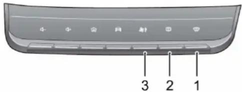
text_image
3 2 1I Defrost/Demist Button
2 Heated Rear Window Button
3 A/C Control Shortcut
Seats&Restraints
116Seats
122SeatBelts
133 AirbagSupplementaryRestraint System
142ChildRestraints
SEATS&RESTRAINTS
Seats
Overview

Toavoidpersonalinjuriesduetothelossof control,DONOTadjusttheseatswhilethe carismoving.
Anidealpositionoftheseatshouldmakesureyourdriving positioniscomfortable,whichallowsyoutoholdthe steeringwheelwithyourarmsandlegsslightlybentand controlalltheequipment.Makesureyourdrivingposition iscomfortableandenablesyoutomaintainfullcontrol of thevehicle.
DONOTreclinethefrontseatbackrestexcessively. Optimumbenefitisobtainedfromtheseatbeltwiththe backrestanglesettoapproximately25°fromtheupright (vertical). Thedriverandfrontpassengerseatsshouldbe positionedasfarrearwardaspractical. T akecarewhen adjustingtheheightofthefrontseat-thefeetofthe rearpassengercouldbecometrappedwhenteseatis lowered. Aproperlyadjustedseathelpsreducetheriskof injuryfromsittingtooclosetoaninflatingairbag.
HeadRestraint

Adjusttheheightoftheheadrestraintsothat thetopofitisinlinewiththetopofthe occupant'shead. Thislocationmayreduce theriskofheadandneckinjuriesintheevent ofacollision.DONOTadjustorremovethe headrestraintswhilethecarismoving.

DONOThanganythingonanyheadrestraint orheadrestraintrod.
Theheadrestraintisdesignedtopreventrearward movementoftheheadintheeventofacollisionor emergencybraking,therebyreducingtheriskofheadand neckinjuries.
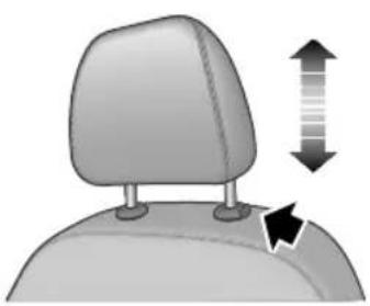
natural_image
Illustration of a car headrest with directional arrows indicating movement or change (no text or symbols)Whenadjustingaheadrestraintfromlowtohighposition, pulltheheadrestraintdirectlyupward,andgentlypress itdownwardafteritreachesthedesiredpositionto makesurethatitislockedinposition.T oremovethe headrestraint,pressandholdtheguidesleevebutton(as indicatedbythearrow)ontheleftoftheheadrestraint, thenpulltheheadrestraintupwardtoremoveit.
Whenadjustingaheadrestraintfromhightolowposition, presstheguidesleevebutton(asindicatedbythearrow)on theleftoftheheadrestraint,andpresstheheadrestraint downward; releasethebuttonafteritreachesthedesired position,andgentlypresstheheadrestraintdownwardto makesurethatitislockedinposition.
FrontSeats
ManualSeat *
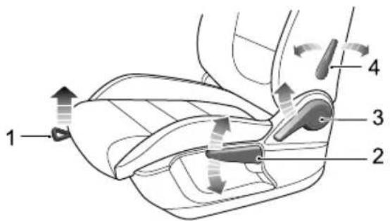
text_image
1 2 3 4•Forward/RearwardAdjustment
Liftthelever(1)undertheseatcushion,slidetheseat intoanappropriatepositionandreleasethelever.Make surethattheseatislockedinplace.
SEATS&RESTRAINTS
• CushionHeightAdjustment
Liftthehandle(2)repeatedlytoraisetheseatcushion; pressthehandledownwardtolowertheseatcushion.
- BackrestAdjustment
Liftthehandle(3),adjustthebackrestuntilimovesinto asatisfiableposition,putdownthelever.
•LumbarSupportAdjustment
Movethelever(4)toadjustthelevelofthelumbar support.
PowerSeat *
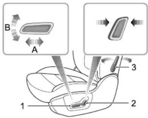
text_image
B A 1 2 3-Forward/RearwardAdjustment
Pushtheswitch(1)forwardorbackward(A)tomove theseatforward/backward.
• CushionHeightAdjustment
Pulltheswitch(I) upward or pushdownward(B) to raise or lower these at cushion.
SEATS&RESTRAINTS
- BackrestAdjustment
Movetheswitch(2)forward/backwardtoadjustthe backrestuntiltreachesthedesiredangle.
•LumbarSupportAdjustment
Movethelever(3)toadjustthelevelofthelumbar support.
RearSeats
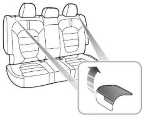
natural_image
Diagram of a car backseat with seatbelt and side panel, showing internal seating arrangement and a close-up of the seat (no text or symbols)AdjustmentofRearSeatBackrest
Pullthecontrolleverlocatedatthetopoftherear seatbackrestupwardstoreleasethelockedstateofthe backrest;thenadjustthebackresttothedesiredposition, releasethelever.Ensurethebackrestiscompletelylocked inposition.
SEATS&RESTRAINTS
FoldingRearSeats
T oincreasetheluggagespace,therearseatbackrest canbefullyfoldedforward.Whenfoldingthebackrest, completelyinserttherearseatbeltbuckleintothe correspondingslotfirst,thenfullylower(orremove)all headrestraints,pulltherespectivecontrolleveratthetop oftheseatbackrestupwardsandfoldtheseatbackrest forward.
T oreturnthebackresttoanuprightposition,pullthe respectivecontrolleveratthetopofthebackrestto releasethelock,raisetherearseatbackrest,whenthe desireduprightpositionisreached,a'click'willbeheard. Ensurethebackrestislockedinposition.
Note: When returning therearseatbackrest to the desired position, makesure that therearseatbelt is not trapped.
Note: Whentheheadrestraintoftherearseatis notfullyloweredorthebackrestofthefrontseatis inclinedbackwardexcessively, the foldingoftherear seatisverylikelytodamagethebackofthefrontseat,
smallstoragecompartmentorheadrestraintofthe rearseat.
Note: If therearseatbeltbuckleisnotcompletely inserted into the correspondings of folding the backrest is very likely to damagetherearseatbackrest coverorfoam.
FrontSeatHeating \*

Ifbareskinisincontactwiththeheatedseats forexcessiveperiodsoftime,itmaycause burns.
Theseatcushionandbackrestoffrontseatsareprovided withheatingelements.Afterstartingthecar,accesstheair conditioningcontrolinterfaceandpresstheseatheating switchonthedisplaytoenabletheheatingfunctionofthe correspondingseat.

Whenpressingaseatheaterswitch,the ingseatwillbecomewarm.Presstheswitch theheatingfunctionWhentheseat
heatingfunctionisactivated,theoperatingindicatorinthe switchilluminates.Whentheseatkushionandbackrest temperaturereachesapproximate38°C,theheating functionwillbedeactivatedautomatically.
IMPORTANT
•DONOTcovertheheatedseatswithblankets, cushionsorotherinsulationtypeobjectors materials.
- If theseattemperaturehasreached38°Cand continuesgettinghotterwhenusingseatheating system, pleaseturnofftheseatheatingandcontact anMGAuthorisedRepairer.
Overuse driver heated an nausea drowsiness and could affect safety.
SEATS&RESTRAINTS
SeatBelts

It is important that all seat belts are worn correctly. Always check that all passengers are wearing seat belts. DONOT carry passenger that are unable to wear correctly positioned seat belts. Wearing seat belts incorrectly may cause serious injury over death in the event of a collision.

Airbags cannot replace seat belts. Airbags carry out support trigger air traffic accidents will trigger airbags. Whether airbags are triggered, seat belt can reduce the risk of serious injury or death in accidents. Therefore, seat belts must beworncorrectly.

NEVERunfastenaseatbeltwhilstdriving. Seriousinjuryordeathmayoccurinthecase ofanaccidentoremergencybraking.

NEVERfastenthedriverseatbeltoruse buckleplacementwheldriver seatisvacantorwhenexitingthevehicle. Thisukhusanginstart automatically.
This vehicle equipped with seat warning indyoutofastenyourseatbelt.
Duringdriving,seatbeltsmustbefastened,thisisbecause: Youcamevpredictifyouwilbeinvolvedmcollision accidentandhowserioususitmaybe. Inmanycasesofcollisionaccidents,passengerswith seatbeltscorrectlyfastenedarewell-protected,while passengerswithseatbeltsnotfastenedsufferfrom seriousinjuryorevendeath. Therefore,allpassengersmustwearseatbeltscorrectly, evenduringshort-distancejourneys.
SEATS&RESTRAINTS
ProtectionProvidedbySeatBelts

Itisofequalimportanceforpassengersinthe rearseattofastentheirseatbeltscorrectly. Otherwise,passengerswithseatbeltsnot correctlyfastenedwillbethrownforwardin accidents,andwillendangerthemselvesas wellasthedriverandotherpassengers.
Whenthevehicleisinmotion,thetravellingspeedofthe occupantsisidenticaltothatofthevehicle.
Intheeventofa'headoncollision'oremergencybraking, thevehiclemaystop,buttheoccupantswillcarryon travellinguntiltheycomeintocontactwithastationary object.
Thisobjectmaybetheeeringwheeldashboard, windscreenandothers.Acorrectlyfastenedseatbeltwill eliminatethisriskofinjury.
Whentheseatbeltisworncorrectlywilllock automaticallyincollisionaccidentsoremergencybraking toreduceyourspeedtogetherwiththevehicle,soasto
preventtheout-of-controlmovementwhichmaycause seriousinjurytodriverandpassengers.
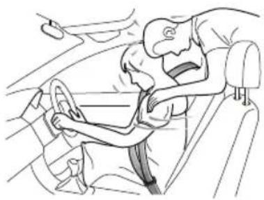
natural_image
Line drawing of a person inside a car seatbelt, showing a surprised expression (no text or symbols)SEATS&RESTRAINTS
WearingSeatBelts

Incorrectlywornseatbeltscouldcauseinjury ordeathintheeventofanaccident.

Seatbeltsaredesignedforoneperson.DO NOTshareseatbelts.

DONOTwrapaseatbeltaroundwhen holdingababyorchildinyourarms.

Removeanyheavycoatsorclothingwhen wearingaseatbelt,failuretodosocanaffect protectionprovidedbytheseatbelt.

Seatbeltsshouldnotbewrappedaround hardorsharpobjectssuchaspens,spectacles orkeystoavoidadditionalinjurytothe users.

Seatbeltscannotfunctioncorrectlywhenthe seatsarereclinedexcessively.DONOTdrive whentheseatsareexcessivelyreclined.
Theseatbeltsfittedtoyourvehiclearedesignedforuse bynormalsizedadults. Thispartoftheliteraturerefersto adultuse.Foradviceonseatbeltusewithchildren,please see'ChildrenandSeatBelts'.
Allseatbeltsare3pointlap-diagonalbelts.
Inordertomaintaineffectiveprotection, the passengers must sit in the correct orientation, feet placed on the floor in front of them, with an upright body (no excessiverecline) and these at belt correctly fastened.
SEATS&RESTRAINTS
FasteningSeatBelts
Please follow the instructions below to fast these seat belts correctly.
I Adjusttheseatcorrectly.
2Holdthemetaltab, pulltheseatbeltoutsteadilyover theshoulderandacrossyourchest. Ensurethereisnotwistonthebelt.
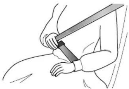
natural_image
Illustration of a person using a bandage to tighten the knee (no text or symbols present)3Insertthemetaltabintothebuckleuntilyouheara 'click', this indicates these seat belt is securely locked.

natural_image
Diagram showing two electrical connectors with a downward arrow indicating a process or transformation (no text or symbols present)4Removeanyslacknessinthebeltbypullinguponthe diagonalsectionofthebelt.
5T oreleasetheseatbelt, presstheredbuttononthe buckle. Theseatbeltwillretractautomaticallytoits originalplace.
SEATS&RESTRAINTS
IMPORTANT
•Alwaysensuretheseatbeltwillnotbecometrapped inthedooraperturewhenclosingthedoor ,damage willoccur.
- Pullingtheseatbeltouttooquicklymaycauseitto 'lock'.Inthiscase,allowtheseatbelttoretract slightlyandthenpullitacrossyourbodyslowly.
•Ifitisdifficulttopulltheseatbeltout,itmaybedue totwistedwebbing.Ifthisisthecase,fullyextract theseatbelt,removethetwist,allowtheseatbelt toretractslowly.
- Whenusingtherearseatbeltspleaseensurethey arefullyretractedintothecorrectpositiontoavoid jammingintherearseatcatches.Eveniftheseat beltisnotcompletelysmoothed,itisstillrequired tobewornduringdriving,butthetwistedpartofthe seatbeltshallnotcontactthepassenger.Whenthis happens,pleasegotoanMGAuthorisedRepairer forrepair.
CorrectRoutingoftheSeatBelts

Ensuretheseatbeltiscorrectlypositionedon thebody,NEVERcrosstheneckorabdomen, NEVERpastheseatbeltbehindthebackor underthearms.
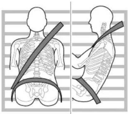
natural_image
Side-by-side illustrations of human torso showing skeletal contours and a belt, no text or symbols presentWhenwearingseatbelts,thelapbeltsectionsshouldbe positionedaslowaspossibleacrossyourhips.Nevercross theabdomen.Intheeventofacollision,thelapbeltcan applyaforceonthehipsandreducethepossibilityofyou
SEATS&RESTRAINTS
slippingunderthelapbelt.Ifyouslipunderthelapbelt,the beltwillapplyforceonyourabdomen,whichmaycause seriousorfatalinjuries.Thediagonalsectionofthebelt shouldcrossthemiddleoftheshoulderandthechest.In theeventofemergencybrakingorcollision,thediagonal sectionofthebeltwillbelocked.Neverpositionaseat beltacrossyourneck,acrossthebodyunderyourarmsor behindyourback.
To ensure that these seat belts always provide maximum protection, ensure the belt is flat, not loose and contacts the body.
UpperAnchorageHeightAdjustment

Duringdriving, DONOTadjusttheheightof seatbelt.

Ensure the fixing point of seat belt is adjusted to the proper height and locked before driving, otherwise injury overendeath may occur in collision accidents.
The vehicle is equipped with seat belt fixing point adjuster on driver seat and front passenger seat. Adjust the height so that the diagonal section of the belt crosses them middle of the should these belt should be positioned away from the neck and head and in a manner where the occupant cannot slide under the belt. Incorrect positioning will reduce the efficiency of these belt in the event of a collision or emergency braking.
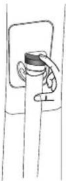
natural_image
Simple line drawing of a hand holding a small object, no text or symbols presentAdjustingtheseatbeltfixingpointcorrectly. Holdtheseatbelt.
SEATS&RESTRAINTS
2Pressreleasebuttonandmovetheheightadjusterto desiredposition.Movtheadjusterbypushingthe slider.
3 Aftermovingheadjustertodesiredposition, release thebuttonandtrytomovetheadjusterdownwardto determinewhetheritislockedinplace.
SeatBeltsDuringPregnancy
Wearingcorrectlypositionedseatbeltswillprovide protectionforbothmotherandunbornchildintheevent ofacollisionoremergencybraking.
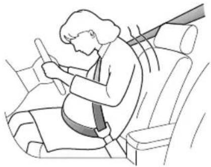
natural_image
Illustration of a person sitting in a car seat, using a seatbelt to interact (no text or symbols present)Thediagonalsectionoftheseatbeltshouldpassacross thechestasnormal,thelapsectionofthebeltshouldpass belowthebelly,lowandsnugonthehipbones.NEVER positionthebeltonorabovethebelly.
Please consult your physician for further details.
SeatBeltsandDisabilities
Itisalegalrequirementthatallooccupantswearseatbelts, thisincludepeoplewithdisabilities.
Dependinguponthedisability,consultyourphysicianfor furtherdetails.
SEATS&RESTRAINTS
ChildrenandSeatBelts

Properprotectionmeasuresmustbetaken forchildrenduringdriving.
Forsafetyreasons, childrenshallrideinchildrestraint devicefixedtotherearseat.
Infants

Only recommended child restraint suitable for the age, height and weight of the child should be used.

NEVERcarryachildorinfantwithyourarms duringdriving. Whencollisionaccidents occur, theweightofchildwillproduceso greatforcethatyoucannotholdthechild. Thechildwillbethrownforwardandsuffer seriousinjuryorevendeath.
Theseatbeltsfittedtoyourvehiclearedesignedforadults, theyarenotsuitableforchildren.Intheeventofan accidentorcollisionthechildrenarenotsecure,itcould causedeathorseriousinjury.
InfantsMUSTuseasuitablechildrestraintdevice.Please consultthechildseatmanufacturersguidelineswhen selectingthecorrectseat.Followthemanufacturers instructionsoninstallation.Pleasereferto"Child Restraints"inthischapterformoredetails.
OlderChildren

NEVERshareaseatbeltamongstchildren. Intheeventofanaccidentorcollisionthe childrenarenotsecure,itcouldcausedeath orseriousinjury.
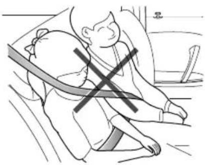
natural_image
Illustration of a person sitting on the floor with a cross symbol indicating pressure or stress (no text or symbols present)SEATS&RESTRAINTS
Aschildrengrowandbecomeolder/largeritwillgettothe stagewhentheynolongerrequirechildseatrestraints,at thispointtheywillrequireuseofthevehiclestandardseat belt.Pleaseensuretheseatbeltiscorrectlypositionedon thebodyofthechild.
When fastening seat belt for a child always check it for correct positioning. Adjust the height of seat belt to ensure the shoulder belt is kept away from the child's face and neck. Position the lap belt acrosst the hips as low as possible, and tighten adequately. Correct positioning means that these seat belt can pass the applied forceto the strongest part of child's body in accidents.
If the shoulder belt to oocloseto child's face or neck, it may be necessary to use a child boost or cushion (always ensure that it meets any relevant laws or standards.
SeatBeltPre-tensioners

Theseatbeltpre-tensionerswillonly beactivatedonceandthenMUST BEREPLACED.Failuretoreplacethe pre-tensionerswillreducetheefficiencyof thevehicle'sfrontrestraintsystem.

If the pre-tensioners have been activated, the seat belt will still function as restraints, and must beworn in the event that the vehicle remains in drivable condition. These at beltpre-tensioners should bere placed at the earliest opportunity by an MGA authorised Repairer.
The vehicle fitted with seat before tensionersthes are designed to retract these seat belts and work in conjunction with the air bags in the event of a severe collision. They are designed to retract these seat belt and secure the occupant in theseat.
Theairbagwarninglightontheinstrumentpackwill aetherive anyalfunction of seabelt
pretensioners.(see'WarningLampsandIndicators'inthe 'InstrumentsandControls'chapter).
Theseatbeltpre-tensionerscanonlybeactivatedonce, afteractivationtheymustbereplaced. Thismayalso involvereplacementofotherSRScomponents.Please referto'ReplacingAirbagSystemParts'.
IMPORT ANT
- Seatbeltpre-tensionerswillnotbeactivatedby minorimpacts.
• Theremovalorreplacementofapre-tensionermust becarriedoutbythemanufacturertrained, dealer technicians. - 10 years from the initial date of registration (or installation date of replacement seat belt pre-tensioner), some components will need to be placed. The appropriate page of Service Portfolio unsigned stamped no the work has been completed.
Seilled Maintenanced Replacement
SeatBeltChecks

Split, worrfrayedseatbeltsmayot functioncorrectlyintheeventofacollision, ifthereareanysignsofdamage,replacethe beltimmediately.

Alwaysensuretheredreleasebuttononthe seatbeltbuckleispointingupwardstoensure easyreleaseintheeventofanemergency.
Please follow the instructions below to check these seat belt warning lamp, seabel metal, buckle, etractor and fixing device regularly:
Insertheabelmetalintohecorresponding buckleanpullseatbeltwebbinglosetothebuckle quicklytocheckthatthebeltclasplocks.
- Holdthemetaltabandpulltheseatbeltforwardquickly tocheckthattheseatbeltreellocksautomatically, preventingthewebbingfromextending.
SEATS&RESTRAINTS
- Fullyextracttheseatbeltandvisiblyexaminefortwists, fraying, splitsorwornareas.
- Fullyextracttheseatbeltandallowtoreturnslowlyto ensurecontinualandcompletesmoothoperation.
- Visiblyexaminetheseatbeltformissingorbroken components.
- Ensuretheseatbeltwarningsystemisfullyfunctional. Iftheseatbeltfailsanyoftheabovetestsorinspections contactanMGAuthorisedRepairerimmediatelyfor repairs.
SeatBeltMaintenance

DONOTattempttoremove, install, modify, disassembleordisposeoftheseatbelts. Have any necessary repairs carried out by your MG Authorised Repairer. Inappropriate handling may lead to incorrect operation.

Ensure no foreign or sharp objects become lodged in these at belt mechanisms. DO NOT allow liquid to contaminate these at belt buckle, this could affect the buckle engagement.
Seatbeltsshouldonlybecleanedwithwarmsoapywater. DONOTuseanysolventtocleantheseatbelt.DONOT attempttobleachordyetheseatbelt,itmayweakenthe seatbelAftercleaning,wipewithaclothandallowto dry.DONOTallowtheseatbelttofullyretractbeforeit iscompletelydry.Keepseatbeltscleananddry.
If there are contaminants accumulated in theretractor, the retraction of these at belt will beslow. Please use a clean and dry cloth to remove any contaminants.
ReplacingSeatBelts

Collisionaccidentsmaydamagetheseatbelt systemtheseatbeltsystemmaynotbe abletoprotectusersafterdamagewhichmay resultinseriousinjuryorevendeathAfter anaccident,seatbeltsshouldbecheckedand replacedasneededimmediately.
Seatbeltsshouldnotrequirechangeafterminorcollisions, however, someotherpartsoftheseatbeltsystemmay requireattentibPleaseconsultMAuthorised Repairerforadvice.
SEATS&RESTRAINTS
AirbagSupplementaryRestraint System
Overview

TheairbagSRSprovidesADDITIONAL protectioninaseverefrontalimpactonly.It doesnotreplacetheneed,orrequirementto wearaseatbelt.

The airbagstogether with these at belts provide optimum protection for adults, but it is not the case for infants. These at belt and air bags systems in the vehicle are not designed for protecting infant protection required by infant should be provided by child restraints.
TheAirbagSupplementaryRestraintSystemgenerally consistsof:
- FrontAirbags(fittedtothecentreofthesteeringwheel anddashboardabovetheglovecompartment)
- SeatSideAirbags(fittedtotheoutersideoftheseatsquab) - SideHeadImpactProtectionAirbags(fittedbehindtheheadlining)
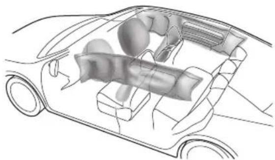
natural_image
Technical illustration of a car interior showing internal components (no text or labels)Inthecorrespondingplacewhereairbagsarefitted,there isawarningsignstating'AIRBAG'.
SEATS&RESTRAINTS
AirbagWarningLight

Theairbagwarninglightislocatedinthe instrumentpack.Ifthislampdoesnotextinguishor illuminatesduringdriving,itindicatesthatthereisafailure intheSRSorseatbelt.PleaseseekanMGAuthorised Repairerattheearliestopportunity.AnSRSorseatbelt faultmaymeanthecomponentsmaynotbedeployedin theeventofanaccident.
AirbagDeployment

Frontseatpassengersshouldnotplacefeet, kneesoranyotherpartofthebodyincontact with,orincloseproximitytoafrontairbag.

Tominimisetheriskofaccidentalinjuryfrom inflatingairbags,seatbeltsshouldbeworn correctlyatalltimes.Inaddition,bothdriver andfrontseatpassengersshouldadjusttheir seattoprovidesufficientdistancefromthe frontairbags.Ifsideairbags/sideheadimpact protectionairbagsarefitted,bothdriverand frontseatpassengeshouldbeseatetb maintainsufficientdistancefromtheupper partofthebodytothesidesofthevehicle, thiswillensuremaximumprotectionwhen thesideairbags/sideheadimpactprotection airbagsaredeployed.
SEATS&RESTRAINTS

Whenairbagsaredeployed, childrenwithout properprotectionmaysufferfromserious injuryorevendeath.DONOTcarrychildren inthearmsoronthekneesduringtraveling. Childrenshouldwearseatbeltssuitableto age.DONOTleanoutofwindows.

Aninflatingairbagcancausefacialabrasions andotherinjuriesiftheoccupantistooclose totheairbagatthetimeofitsdeployment.

DONOTaffixorplaceanyobjectson, or adjacenttotheairbags. This may affect the airbagpassageorcreateprojectilesthatmay cause injuryorseriousharmintheeventof airbagdeployment.

Afterdeploymenttheairbagcomponents becomeveryhot.DONOTtouchanyairbag relatedcomponents,itmaycauseburnsor seriousinjury.

DONOTknockorstrikethepositionwhere airbagsorrelatedpartsarelocated,soas toavoidaccidentalairbagdeploymentwhich maycauseseriousinjuryorevendeath.
Intheeventofacollision, theairbagcontrolunitmonitors therateofdecelerationoraccelerationinducedbythe collision,todeterminewhethertheairbagsshouldbe deployed.Airbagdeploymentisvirtuallyinstantaneous andoccurswithconsiderableforce,accompaniedbya loudnoise.
Provided the front seat occupants are correctly seated and with seat belts properly worn, the air bags will provide additional protection to the chest and facial areas in the event of the car receiving a severe frontal impact.
Sideairbagsandsideheadimpactprotectionairbagsare designedtoofferadditionalprotectiontothesideofthe bodyfacingtheimpact,ifaseveresidecollisionoccurs.
SEATS&RESTRAINTS
IMPORTANT
•Airbags cannot protect lower body part sof passengers.
- Airbagsarenotdesignedforrearcollision,minor frontalorsideimpacts,orifthevehicleoverturns; norwillitoperateasaresultofheavybraking.
- Deployment and retraction of the frontal and side air bag stakes place every quickly and will not protect against the effect of secondary impact that may occur.
- Whenanairbaginflates,afinepowderisreleased. Thisisnotanindicationofamalfunction,however, thepowdermaycauseirritationtotheskinand shouldbethoroughlyflushedfromtheeyesandany cutsorabrasionsoftheskin.
•Afterinflation,frontandsideairbagsdeflate immediately. Thisprovidesagradualcushioning effectfortheoccupantandalsoensuresthatthe driver'sforwardvisionisnotobscured.
FrontAirbags

NEVERusearearwardfacingchildrestraint onaseatprotectedbyanACTIVEAIRBAG infrontofit,DEA THorSERIOUSINJURYto theCHILDcaroccur.Referto'Disablingthe PassengerAirbag'.

Frontseatpassengersshouldnotplacefeet, kneesoranyotherpartofthebodyincontact with,orincloseproximitytoafrontairbag.

lextremeasedrivingneynevensurfacesaycausairbagdeployment. Pleasetakeextracarewhendrivingonunevenroads.
Airbagsaredesignedtodeployduringseriousimpacts,the followingconditionsmaycauseairbagdeployment.
- Afrontalcollisionwithunmovableornondeformable solidobjectsatahighspeed.
- Conditionsthatcancauseseriouschassisdamage,such asacollisionwithkerbstones,roadedges,deepravines orholes.
SeatSideAirbags

Themanufactureandmaterialoftheseat iscriticaltothecorrectoperationofside airbags. Therefore,pleaseDONOTfit seatcoverswhichmayaffectsideairbag deployment.
Intheeventofaserioussideimpact,therelevantsideairbag willdeploy(onlytheaffectedside).
•Theairbagwillbedeployedintheeventthatthesideof thevehicleisimpactedwithasolidobjectoranother vehicle.
SideHeadImpactProtectionAirbags
Ithevenoferiousidempacthelevanside curtainairbagwilldeploy(onlytheaffectedside).
- Thesidecurtainairbagwillbedeployedintheeventthat thesideofthevehicleisimpactedwithasolidobjector anothervehicle.
Condition Which Airbag Not Deploy
The deployment of airbags does not depend on the vehicle speed, which has a single impact and therate at which the carchangess speed as result of a collision. When the impact force of collision is absorbed, dispersed to vehicle body, airbags may not deploy; however, airbags may sometimes deploy according to impact condition. Therefore, the deployment of airbags shall not be judged based on these severity of vehicle damage.
FrontAirbags
Undercertainconditionsthefrontairbagsmaynotbe deployedSomeexamplesarelistedbelow:
•Theimpactpointisnotcentraltothefrontofthe vehicle.
•Theimpactisnotofsufficientforce(theimpactiswith anobjectthatisnotsolid,suchasalamppostorcentral barriers).
•Theimpactareaishigh(collisionwiththetailgateofatruck).
- Impactstotherearorsideofthevehicle.
SEATS&RESTRAINTS
•Thevehiclerollingover .
•Frontalcollisionatananglewithguardbars.
SeatSideAirbagsandSideHeadImpact ProtectionAirbags
Undercertainconditiontheseatsideandsidehead airbagsmaynotbedeployed.Someexamplesarelisted below:
•Sideimpactsatcertainangles.
•Lightsideimpactssuchasamotorcycle.
- Impactsthatarenotcentraltothesideofthevehicle, eithertoofartowardtheenginecompartmentorthe loadspace.
•Thevehiclerollingover.
•Frontalcollisionatananglewithguardbars.
• The angled impact is not of sufficient force (the impact is with an object that is not solid, such as a lamppost or central barriers).
•The impact is not of sufficient force (with another vehicle, stationary or moving).
•Theimpactisfromtherearofthevehicle.
DisablingthePassengerAirbag
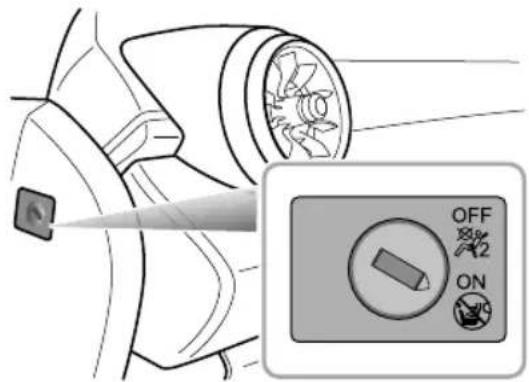
text_image
OFF 4x 4x ONThe passengerairbagswitchislocatedattheleft instrumentpanelendcoverplate.Insertthekeyandturn theswitchtoonoroffpositiontoenableordisablethe passengerairbag.
Note: The Passenger Airbag should only be disabled when are near facing child seat is fitted to the front passenger seat.
SEATS&RESTRAINTS
Note: When an adult is seated in the front passenger seat, ensure that the air bag is switched on.
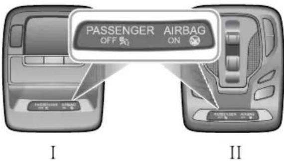
text_image
PASSENGER AIRBAG OFF ON I IIThepassengerairbagstatuslightislocatedintheroof mountedinteriorlampassembly.Theshapeofthelamp assemblyvariesaccordingtotheconfigurationofthe vehicle.
WhentheswitchisturnedtotheOFFposition,theOFF indicatorlight(locatedinthePABdisplaypanelinthelamp
assembly)illuminates,thisindicatesthatthepassenger airbagisdisabled.
WhentheswitchisturnedtotheONposition,theON indicatorlight(locatedinthePABdisplaypanelinthelamp assembly)illuminates,thisindicatesthatthepassenger airbagisenabled.
SEATS&RESTRAINTS
ServiceandReplacementofAirbags
ServiceInformation

DONOTinstallormodifytheairbag.Any changestothevehiclestructureorairbag systemwiringharnessarestrictlyprohibited.

Changestovehiclestructureisprohibited. This may affect thenormaloperationofthe SRS.

DONOTallowtheseareastobefloodedwith liquidandDONOTusepetrol,detergent, furniturecreamorpolishes.

IfwatercontaminatesorenterstheSRSit maycausedamageandaffectdeployment. InthiscasecontactanMGAuthorised Repairerimmediately.
T opreventdamagetotheairbagSRS, the following areasshouldbecleanedsparinglywithadampclothand upholsterycleanerONLY:
•Steeringwheelcentrepad.
• Areaofdashboardcontainingthepassengerairbag.
Areobdingnftorpillafinisherwhich enclosethesideheadimpactprotectionmodules. Iftheairbagwarninglampfailstoilluminate,stayson,or ifthereisdamagetothefrontorsideofthevehicle,or theairbagcoversshowsignsofdamage,contactanMG AuthorisedRepairerimmediately.
IMPORTANT
•Theremovalorreplacementofanairbagmodule shouldbecarriedoutbyanMGAuthorisedRepairer.
• After 10 years from the initial date of registration (or installation date of replacement airbag), some components will need to be replaced by an MG Authorised Repairer. The appropriate page of the Service Portfolio must be designed and stamped once the work has been completed.
ReplacingAribagSystemParts

Eveniftheairbagdoesnotdeploy,collisions maycausedamagetoSRSinthevehicle. Airbagsmaynotfunctionproperlyafter damage,andcannotprotectyouandother passengerswhenasecondcollisionoccurs, whichmaycauseseriousinjuryoreven death.ToensurethatSRScanfunction properlyaftercollision,pleasegotoanMG AuthorisedRepairertocheckairbagsand repairasnecessary.
Airbagsaredesignedforusingonceonly.Oncetheairbag isdeployed,youmustreplaceSRSparts.Pleasegotoan MGAuthorisedRepairerforreplacement.
DisposalofAirbags
When your vehicle is sold, ensure that the new owner knows the vehicle is equipped with airbags, and is aware of there replacement date of SRS.
If the vehicle is scrapped, the undeployed air bags may have potential risks, therefore, before the disposal, they must be
deployedsafelyinacertainenvironmentbyaprofessional fromanMGAuthorisedRepairer.
SEATS&RESTRAINTS
ChildRestraints
ImportantSafetyInstructionsaboutUsing ChildRestraints
It is recommended that children below the age of 12 years old should be seated on there are seat of the vehicle, in a childrestraintsystem appropriateto the children's weight and size. Infants less than 2 years old should be restrained in an infant childrestraintsystem.
It is recommended that a child restraint system that complies with UNECE-R44 or ECE-R129 standard are fitted in this vehicle. Checkmarkings on the child restraint system.
Thereareanumberofchildrestraintsystemsavailableof differenttypeandspecification.Foroptimumprotection, itisrecommendedthatyouchooserestrainsystems appropriatetothechild'sageandweight.
It is important to comply with installation instructions supplied by the child restraint manufacturer and that child restraints system is properly secured to the vehicle. Failure to follow these instructions may cause death or serious injury to the child in an event of sudden stop or accident.
- Allooccupants, including children must wear seat belts or use an appropriate child restraint.
- It is recommended that children under 12 years of age or less than 1.5 metres should be appropriate child restraint fitted to the other seat.
•Onlyonechildcanbecarriedinanyonerestraint. - Donotputthechildonthelaporinarmswhensitting inanyseat.
•Alwaysadjusttheseatbackresttoaproperposition andensureitislockedinpositionwheninstallingachild seatorrestraint. - Ifinstallingarearfacingchildrestrainttotherear seat, thecorrespondingfrontseatshouldbeadjusted forward; ifinstallingaforwardfacingchildrestraint totherearseat, youmayneedtoadjusttheheight oftheheadresttothelowest; ifinstallingaforward facingchildrestrainttothefrontseat, youmayneedto removeitsheadrest.
- Neverletyourchildstandorkneelontheseatduring driving.
•Alwaysensurethechilddisseatedcorrectlyinthechild restraint.
SEATS&RESTRAINTS
- Thewaysofusingseatbeltshaveagreatinfluenceon themaximumprotectionofferedbytheseatbelt,you mustcomplywiththechildrestraintmanufacturer's instructionsonproperuseofseatbelts.Ifseatbelts arenotproperlyfastened,aminortrafficaccidentmay alsoleadtoinjury.
- Childrestraintsthatarenotfittedcorrectlymaymove andinjureotheroccupantsintheeventofanaccident oremergencybraking.Therefore,evenifthereisno infantorchildinthechildrestraint,italsoshouldbe fittedproperlyandsecurelyinthevehicle.
WarningsandInstructionsonUseofChild RestraintonFrontPassengerSeat
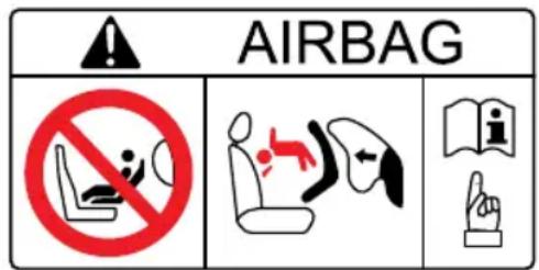
text_image
AIRBAG NO SHOWN i.e. i.e.NEVERused rearward facing midrestraint onaseatprotected by an ACTIVE AIRBAG in front of it, DEATH or SERIOUS INJURY to the CHILD can occur.
Incaseswherethereisaneedtoinstallarear facingchildrestraintonthefrontpassenger seatstehkeydeactivatthfront passengerairbagfunction,orseverinjury orevendeathcanoccur.
Oncethechildrestraintisremovedfromthe frontpassengerseat, usethekeytoreactivate thefrontpassengerairbag.
Wheninstallingachildrestraintonthefront passengeratmovefrontpassenger seatasfarrearwardaspossible.
Useonechildrestraintperchild.
SEATS&RESTRAINTS
Pleasestudythesafetywarninglabelonthesunvisor. Wherepossiblealwaysinstallchildrestraintsontherear seat.lfitisnecessarytoinstallachildrestraintonthefront seatpleaseobservethewarningsabove.
Children's Safety and Side Airbags

Childrenshouldnotbeallowedinareas whereairbagsmaybedeployed,thereisa riskofseriousinjury.

Only recommended child restraint suitable for the age, height and weight of the child should be used.

DONOTplaceanyitemsinareaswhere airbagsmaybedeployed,thereisariskof seriousinjury.
Intheeventofasidecollision,thesideairbagscanprovide betterprotectionforthepassenger .However,when theairbagistriggeredaverystrongexpansionforceis generated,ifthepassenger'sseatingpositionisnotcorrect,
theairbagsoritemsinthesideairbagdeploymentarea maycauseinjury.
Whenthecorrectchildrestraintisusedtosecurethe childproperlyintherearseatandthechild'sseating positioniscorrect,thereisenoughspacebetweenthe childandthesideairbagdeploymentregionfortheairbag todeploywithoutanyhindrance,andthusprovidethe bestprotection.
ChildRestraintsGroups
SecuredUsing3PointlapDiagonalBelts

Please DONOT put therear facing child restraint in the front passenger seat, this may cause serious injury overvendeath.
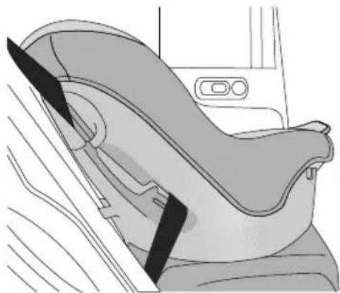
natural_image
Interior view of a car seatbelt device showing seat, seat, and seatbelt (no text or symbols visible)It is recommended that children should always be seated in therearofthe vehicle in a child restraint or restraint system, and fixed with 3 point, lap diagonal seat belts.
ISOFIXChildRestraintSystems

TheISOFIXanchoragesintherearseatare designedforusewithISOFIXsystemsonly.

Childrestraintanchoragesaredesigned towithstandonlythoseloadsimposed by correctlyfittedchildrestraints. Underno circumstancesaretheytobeusedforadult seatbelts, harnesses, orforattachingother itemsorequipmenttothevehicle.
Note: When installing and using any child restraint system, always follow the manufacturer's instructions.
Note: Therearseatsfittedtothisvehicleareprovided withtheISOFIXinterface(asindicatedbythearrowin thefollowingimage),thesearedesignedtoconnectto anISOFIXchildseat.
Fastvehicle-approvedSOFxKlestraint systemstothemountingbrackets.
When using ISOFIX mounting grackets for seat mounting, universally approved child restraints systems for ISOFIX maybe used.
SEATS&RESTRAINTS
Note: When using seat mounting, universally approved child restraints systems, toptether must be used.
Note: Pleaserefertothechildrestraintsystem manufacturer'sinstructionsfordetails.
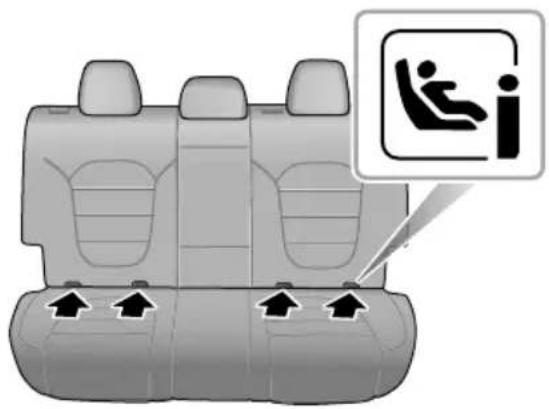
natural_image
Top-down view of a car backseat with seatbelt and seatbelt, showing three seats and four seats with directional arrows (no text or symbols)3T ofastenthetoptetherstrapofthechildrestraint system, routethetetherstrapundertheheadrestraint andattachtotheanchoragehookbeingcarefulnotto
twistthestrap.IfnotusingISOFIXloweranchorages, usingtheseatbelt,completetheinstallationinlinewith thechildrestraintmanufacturersinstructions.
4Afterinstallationapplysuitableforcetoensurethe restraintissecurelyfastened.
Note: When installing and removing any child restraintsystem, always follow the manufacturer's instructions.
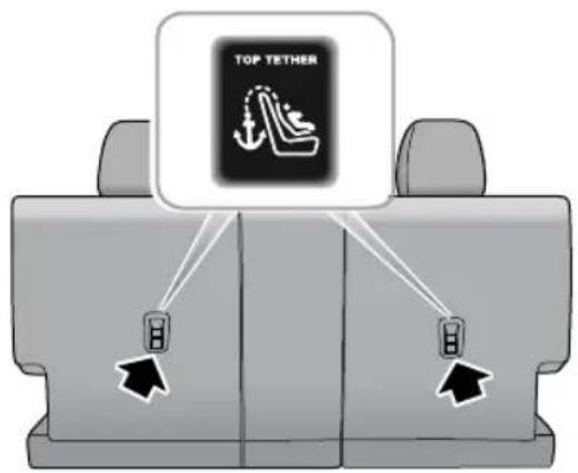
text_image
TOP TETHERApprovedChildRestraintPositions
It is recommended that a child restraints system that complies with UNECE-R44 or ECE-R129 standard are fitted in this vehicle. Checkmarkings on the child restraints system.
ApprovedChildRestraintPositions(fornonISOFIXChildRestraints)
| MassGroup | SeatingPositions | ||||
| FrontPassenger | Rear Outboard | Rear Middle | |||
| WithoutFront PassengerAirbag OFFSwitch | WithFrontPassengerAirbagOFFSwitch | ||||
| AirbagONAirbagOFF | |||||
| 0group(lessthan10kg) | XXUUU | ||||
| 0+group(lessthan13kg) | XXUUU | ||||
| Igroup(9~18kg) | XXUUU | ||||
| IIgroup(15~25kg) | UUUUU | ||||
| IIIgroup(22~36kg) | UUUUU | ||||
| Note:Descriptionoflettersinthetable:U=Suitableforuniversalchildrestraintsystemsapprovedforthismassgroup;X=Seatpositionnotsuitableforchildrestraintsystemsinthismassgroup. | |||||
SEATS&RESTRAINTS
ApprovedChildRestraintPositions(forISOFIXChildRestraints)
| SeatingPosition | Massgroupcategories | ||||
| 0group0+group | Igroup | ||||
| RearfacingForwardfacingRearfacing | |||||
| Upto29lbs(13kg)20–40lbs(9 ~ 18kg) | |||||
| FrontPassenger Seat | SizeClass | NotISOFIXequipped | |||
| SeatT ype | |||||
| RearOutboard SeatISOFIX | SizeClassC,D,E | ^1 | A,B,BI ^1 | C,D ^1 | |
| SeatT ype | IL ^2 | IL ^2 ,IUF ^3 | IL ^2 | ||
| RearCentreSeat | SizeClass | NotISOFIXequipped | |||
| SeatT ype | |||||
Note: ILSuitableforparticularISOFIXchildrestraintssystemsofthesemi-universalcategory.Pleaseconsultchildrestraints systemssuppliers'vehiclerecommendationlists;
IUSuitable for SOFIX forwarding hild restraintsystem of universal category approved using this mass group and ISOFIX size class;
^1 ThdSOFIXsizelassolbothuniversalandemi-universathildeasystemsidefinedbythecapitalettergradeA \~ G. TheseidentificationlettersaredisplayedonthelSOFIXchildseat;
^2 .AttimeofpublishingtherecommendedGroup0+ISOFIXbabysafetyseatistheBritaxRomerBabySafe.ConsultanMGAuthorisedRepairerforthelatestdetailsrelatingtoourrecommendedchildseats;
^3 .AttimeofpublishingtherecommendedGroupIIISOFIXchildseatistheBritaxRomerDuo.ConsultanMGAuthorised Repairerforthelatestdetailsrelatingtoourrecommendedchildseats.
Note:AttimeofpublishingtherecommendedGroupII-IIIISOFIXchildseatistheKidFixIIXPSICTandKidFixanMGAuthorisedRepairerforthelatestdetailsrelatingtoourrecommendedchildseats.
^2 R.Consult
T ableofl-Sizechildseats
Thetablegivesarecommendationforwhichl-Sizechildseatssuitwhichlocations,andforwhatsizeofchild.
ThechildseatmustbeapprovedinaccordancewithUNRegRI29.
| T ypeofchildseat | FrontpassengerseatRearoutboardseatsRearcentreseat | |
| I-Sizechildrestraintsystems | XI-UX |
Note: I-USuitableforusewithforwardandrearfacingl-Sizechildrestraintsystems.
XNotsuitableforusewithl-Sizerestraintsystems.
SEATS&RESTRAINTS
Group0/0+ChildRestraint

Whenthefrontpassengerairbagisactive, neverplacearearfacingchildrestraint on thefrontpassengerseat,severeinjuryoreven deathcanoccur.
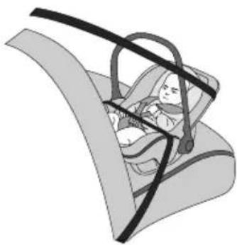
natural_image
Illustration of a baby car seatbelt in a comfort seat, no text or symbols presentChildrestraintsthatcanbeadjustedtolyingposition aremostsuitableforinfantswhoarelighterthan10kg (normallyforthoseyoungerthan9months)orthosewho arelighterthan13kg(normallyforthoseyoungerthan24 months).
Group|ChildRestraint

Whenthefrontpassengerairbagisactive, neverplacearearfacingchildrestraint on thefrontpassengerseat,severeinjuryoreven deathcanoccur.
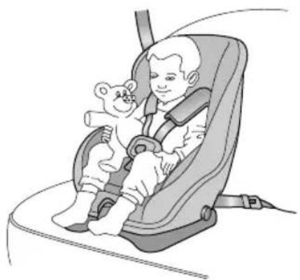
natural_image
Illustration of a child in a baby car seatbelt sitting together (no text or symbols)Backward/forwardchildrestraintsaremostsuitablefor infantswhoseweightis9 \~ 18kg(normallyforthoseolder than9monthsandyoungerthan4yearsold).
SEATS&RESTRAINTS
GroupIIChildRestraint

Thediagonalsectionoftheseatbeltshould passacrosstheshoulderandupperbody, awayfromtheneck. Thelapsectionofthe beltshouldpassacrossthehips,awayfrom theabdomen.
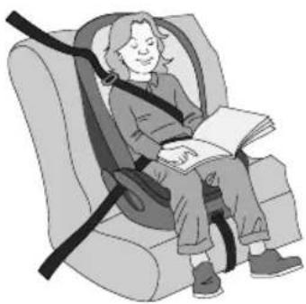
natural_image
Illustration of a person sitting in a car seat using a seatbelt, holding an open book (no text or symbols visible)The combination of child restraint and 3 point lap diagonal seat beltismost suitable for children whose weight is 15 \~ 25 kg (normally forthose older than 3 years old and younger than 7 years old).
GroupIIChildRestraint

Thediagonalsectionoftheseatbeltshould passacrosstheshoulderandupperbody, awayfromtheneck. Thelapsectionofthe beltshouldpassacrossthehips,awayfrom theabdomen.
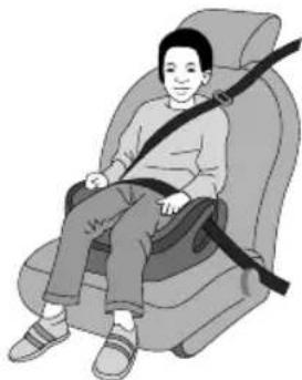
natural_image
Illustration of a person sitting in a car seat with a belt buckle (no text or symbols)The combination of child booster seat and vehicle 3 point lap diagonal seat belt is most suitable for children whose weight is 22 \~ 36 kg and whose height is below 1.5 m (normally forthose about 7 years old to those older than 7 years old).
Starting&Driving
154Keys
158 ChildProofLocks
159AlarmSystems
169StartingandStoppingEngine
I 73EconomicalandEnvironmentalDriving
176 CatalyticConverterandParticulate Filter
I 78FuelSystem
181 ManualTransmission *
183 DualClutchAutomaticTransmission
189DrivingMode *
192BrakeSystem
204StabilityControlSystem(SCS) and TractionControlSystem(TCS)
206TyrePressureMonitoringSystem (TPMS)
207 STOP-STARTIntelligentFuelSaving System
212 CruiseControlSystem
215 Adaptive Cruise Control System
225 ParkingAidSystem
227RearDriverAssistanceSystem
235DrivingAssistSystem
266LoadCarrying
STARTING&DRIVING
Keys
Overview

Pleasekeepthesparekeyinasafeplace-not inthecar!

It is recommended that spare keys are not kept on the same key ring, sincethism may cause interference and prevent correct key recognition and therefore prevent the correct operation of the vehicle powers system.

Thesmartkeycontainsdelicatecircuitsand mustbeprotectedfromimpactandwater damage,hightemperatureandhumidity, directsunlightandtheeffectsofsolvents, waxesandabrasivecleaners.
Y ourvehicleissuppliedwithtwosmartkeys,eachone containsabackupmechanicalkeyblade,thiswilloperate thedriverdoormechanicallock.Thesmartkeyssupplied areprogrammedtothesecuritysystemonthecar,anykey thatisnotprogrammedtothecarwillnotoperatethe keylessentryfunctionorthevehicleimmobiliser.
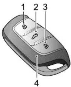
text_image
1 2 3 4ILockButton
2T ailgateButton
3UnlockButton
4SmartKey
Thesmartkeyonlyworkswithinacertainrange.lts workingrangeissometimesinfluencedbythekeybattery condition,physicalandgeographicalfactoforsafety consideration,afteryoulockyourvehiclebythesmartkey, pleaserecheckifthevehicleislocked.
If your key is lost/stolen or broken, are replacement can be obtained from a MGA authorised repairer. The lost/stolen
keycanbedeactivated.Ifthelostkeyisfound,anMG AuthorisedRepairercanreactivateit.
Note: AnykeymadeindependentlyoutsideofMG AuthorisedRepairerNetworkmaynotstartthe engine, and may affect the safety of your car. To obtain suitable key replacement, it is recommended that you can consult MGAuthorisedRepairer.
Note: Thenewkey cannot be offered to you immediately because it requires programming to the vehicle by the MGA authorised Repairer.
Note: When operating your vehicle with the smart key, avoid placing near the devices with a strong radio interference (such as notebook computers and other electronic products), then normal function of the key may be affected.
ReplacingtheBattery
Pleaseusethepictureguidetoreplacethesmartkey batteryifanyofthefollowingconditionsoccur:
- Thesmartkeylocking/unlockingfunctionrangeis reduced;
The engineering mobilisation warning scheme instrumentpaclashThe corresponding alarm icon(referto"WarningLightsandIndicators"in InstrumentsandControls"chapter)willbeshownon themessagecentredispla"SmartKeyNotFound" maybedisplayedforsomemodels.
STARTING&DRIVING
A
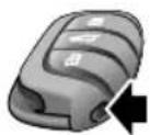
B
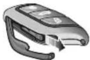
C
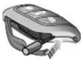
D
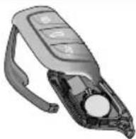
I Pressthebutton(A)onthesmartkeytoejectthe decorativetrim.
2Removethebackupmechanicalkey(B)inthearrowed direction.
3Usingasuitableflatbladedtool,insertthetoolinto thesideofthekey(C),carefullypriseoffthebattery coverandseparatetheupperandlowercasings(D).
4Removethebatteryfromtheslot.
5Putthenewbatteryintheslot, and makesureitisin fullcontactwiththeslot.
Note: Makesurethatthepolarityofbatteryis correct('+'sidefacingdown).
Note: It is recommended to use a CR2032 battery.
6Refitthecoverandpresstightly,ensuringthegap aroundthecoveriseven.
7Refitthemechanicalkey,andclosethedecorativetrim.
8Starttheenginetoresynchronisethekeywiththe vehicle.
IMPORTANT
- Useofanincorrectorinappropriatebatterymay damagethesmartkey. Thenewreplacement'srated voltage, sizesandspecificationsmustbethesameas theoldone.
•Incorrectfittingofthebatterymaydamagethekey. - Disposaloftheusedbatterymustbestrictlyin accordancewithrelevantenvironmentalprotection acts.
STARTING&DRIVING
ChildProofLocks

NEVERleavechildrenunsupervisedinthe car.
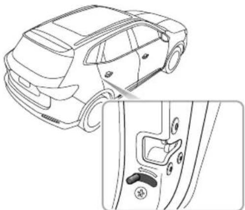
natural_image
Line drawing of a car showing front and side views of the door handle (no text or symbols)Stepsforenablingordisablingthechildprooflocksareas follows:
- Openthereardooratcorrespondingside,move thechildprooflocklevertothelockpositioninthe directionofthearrowtoengagethechildprooflock;
- Movethelevertotheunlockpositioninthereverse directionofthearrowtodisablethechildprooflock. Withthechildprooflocklocked,thereardooratthe correspondingsidecannotbeopenedfrominsidethecar, butcanbeopenedfromoutsidethecar .
AlarmSystems
Y ourvehicleisfittedwithanengineimmobilisersystemand avehicleanti-theftsystem.T oensuremaximumsafetyand operationconvenience,westronglyrecommendyouto carefullyreadthischaptertofullyunderstandtheactivation anddeactivationofanti-theftsystems.
Enginelmmobiliser
Anengineimmobiliserisdesignedtosafeguardthevehicle fromtheft.Engineimmobilisationcanonlybedeactivated tostartthecarbyusingthematchedkey.
PressSTARTSTOPbuttonontheinstrumentpanel,oncea validkeyisdetectedinthevehicle,engineimmobiliserwill bedeactivatedautomatically.
Ifthemessagecentredisplays"SmartKeyNotFound"or "PleasePuttheKeyinAlternativeStartingPosition"orthe engineimmobilisersystemwarninglampilluminates,please putthesmartkeyatthebottomofthecentreconsole cupholder(referto"AlternativeStartingProcedure"in "StartingandStoppingEngine"section),ortrytousethe
sparekey.Ifthecarcanstillnotbestarted,seekanMG AuthorisedRepairer.
STARTING&DRIVING
VehicleAnti-theftSystem
LockingandUnlocking
Whenthevehicleislocked,theindicatorlampsflashthree times,andtheanti-theftsystemwarninglampflashes (modeldependant);whenitisunlocked,theturnsignal lampsflashonce.Onsomemodels,youcanunlockall doorsorthedriverdoorusingtheCarsettingsonthe infotainmentdisplay.
OperationofDoorLockSystem(Key)
KeyLocking
- Usingtheremotekeytolock:pressthelockbuttonon thekeytolockthecarafterclosingthedoors,engine bonnetandtailgate.
- Usingthemechanicalkeytolock:partiallyoperate thedoorreleasehandle,usingasuitableflatblade tool,insertthetoolintotheundersideofthetrimand carefullyremovethedoorlocktrimcover,insertthe keyintothedriverdoorlockandturncounterclockwise tolockthecar.
KeyUnlocking
• Usingtheremotekeytounlock press the unlock button on the keytounlock the car.
- Usingthemechanicalkeytounlock:partiallyoperate thedoorreleasehandle,usingasuitableflatblade tool,insertthetoolintotheundersideofthetrimand carefullyremovethedriverdoorlocktrimcover,insert thekeyintothedriverdoorlockandturnclockwise tounlockthecar.
Not the start/stop which is placed in CC or ON/RUNNING position or theremote key unlock is activated within second after the vehicle is unlocked with the mechanical key, the immobiliser alarm will be triggered.
Note: If nonpanels are opened within 30 seconds after the vehicle unlocked by using the remotkey ball doorwill automatically re-lock.
OperationofDoorLockSystem(Keyless)
Thekeylessentrysystemcanlockandunlockthedoors oropenthetailgateaslongasyoucarrythesmartkeyand approachothecar.
STARTING&DRIVING
IMPORTANT
Thesmartkeymustbewithin 1.5metresofthevehicle forthekeylesssystemtooperatecorrectly
KeylessLocking
AfterswitchingofftheengineusingtheSTART/STOP buttonandexitingthecar, pressthedoorhandlebutton oncebeforemovingawayfromthecartolockalldoors andtailgate (noneedtopressthelocbuttononthe key). Note, this will also arm the alarm and immobilise the vehicle.
KeylessUnlocking
Pressthebuttononthefrontdoorhandleoncetounlock thecar,thenpullthedoorhandletoopenthedoor.
Note: Whenthevehicleislocked, if you are within the smart key range and operate the door handle button, but carry out no further action, after 30 seconds the vehicle will automatically re-lock itself to remain secure.
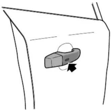
natural_image
Simple line drawing of a car door with a handle and arrow indicating direction (no text or symbols)IMPORTANT
Afterthedoorislockedbyusingthekey,pressthe buttononthedoorhandletounlockthecar.Ifthecar cannotbeunlockedorlockednormally,seekanMG AuthorisedRepairer.
STARTING&DRIVING
Mislock
Ifthedriver'sdoorisnotfullyclosedwhenthesmartkey lockbuttonispressed,orthevehicleignitionsystemhas notbeenswitchedOFF ,thevehiclehornwillsoundonce, indicatingamislock.Inthiscase,noneofthedoorswill lock,thealarmsystemwillnotbearmedandthedirection indicatorlightswillnotflash.
Iflockingoperationisperformedwhenthedriver'sdooris closedbutthepassenger'sdoororbonnetandtailgateare notfullyclosed,thevehiclehornwillsoundonce,indicating amislock.Inthiscase,the'partialarming'attributesofthe bodyanti-theftsystemwillenable(allfullycloseddoors, bonnetortailgateapertureswillbeprotected,butanopen aperturewillnot!).Assoonastheopenapertureis closed,thesystemwillautomaticallyreverttoanarmed state.
InadvertentLockingofKeysinVehicle
If the vehicle is locked using the mechanical key blade or handset whilst starmart key/s remain inside, the following actions will occur:
- Onesmartkeylockedvehicle immobilisationreleasefunctionofthesmartkeylockedinthevehicleissuspended,thelockandunlockfunctionofthemarkjetaineThenginecannobestarted.T oreinstatetheimmobiliserreleasefunctionofthesmartkeylockedinthevehiclethesecondsmartkeyshouldbeusedtounlockthevehicle.Thefunctionwillautomaticallybereinstated.
- Bothsmartkeyslockedinvehicle-Theimmobilisation releasefunctionofbothsmartkeyslockedinthevehicle issuspended,thelockandunlockfunctionofthesmart keysisretained.Theenginecannotbestarted.The reinstatementofkeyfunctionscanonlybecarriedout usingheapprovediagnostitogIonsulaMG AuthorisedRepairerimmediately.
Anti-TheftAlarmSounder
If the anti-theftalarm has been triggered, the car horn will sound continuously. Press the UNLOCK button on the key, the anti-theft alarm will be deactivated.
STARTING&DRIVING
InteriorLockandUnlockSwitch
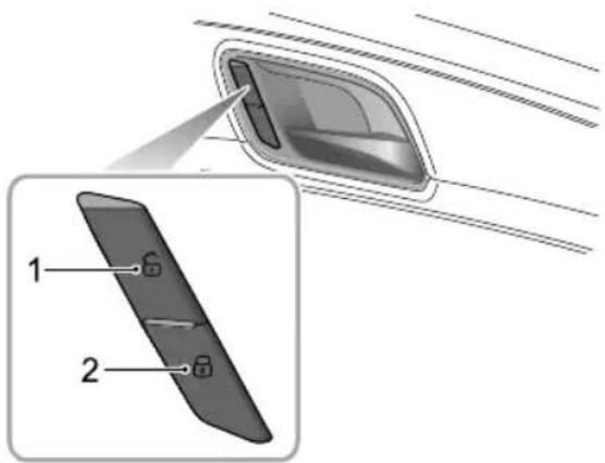
text_image
Diagram showing a device with labeled parts, including a close-up view of the interior panel and a magnified view of its internal structure.IUnlockSwitch
2LockSwitch
Whenthevehicleanti-theftsystemisnotset,pressthelock switch(2)afterclosingalldoorstolockalldoors;pressthe unlockswitch(1)tounlockalldoors.
Note: If the vehicle anti-theft system is set, pressing the lock/unlock switch will not lock/unlock the doors but will trigger the alarms system.
Ifthedoors, bonnetandtailgateareclosed, press the interior lockswitch, they yellow indicator on the interior lockswitchilluminates.
lfamislockiscausedbynon-driverdoor,tailgateorbonnet, presstheinteriorlockswitch,theyellowindicatoronthe interiorlockswitchilluminates.
InteriorDoorHandles
Usetheinteriordoorhandlestoopenthedoor:
I Pulltheinteriordoorhandleoncetounlockthedoor.
2Pulltheinteriordoorhandleagaintoopenthedoor.
SpeedLock
Allthedoorswillbelockedautomaticallywhentheroad speedexceeds10mph(15km/h).
STARTING&DRIVING
AutomaticUnlock
WhenthevehiclepowersystemisswitchedtotheOFF position, allthedoorswillbeunlockedautomatically.
ManualT ailgate\*

If the tail gate cannot be closed due to the type of cargoloaded, besure to close all windows during driving, select the face distribution mode of the air condition, and the blow to maximum speed, so as to decrease exhaust fumesentering the vehicle.
Manualtailgatecanbeopenedbythefollowing2ways: I Whenthecarisunlockedorthematchedkeyappears within Imrangearoundthetailgate, directlypressthe openswitchonthetailgatetoopenthetailgate(A).
2Pressandholdtheopenbutton(B)formorethan 2secondstounlockandreleasethetailgate,then manuallylifttoopenthetailgate.
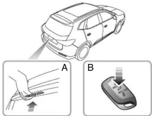
text_image
Diagram illustrating car safety instructions with labeled steps A and B showing hand positioning and device usage.ElectricT ailgate\*

If the tail gate cannot be closed due to the type of cargoloaded, besuret close all windows during driving, select the face distribution mode of the air condition, and set the blowert maximum speed, so as to decrease exhaust fumesentering the vehicle.

Beforeoperatingtheelectrictailgate, ensurenopersons,animalsorobstructions arewithinthedirectvicinityofthetailgate, theymaybecometrappedbetween the tailgateandvehicleortailgate and obstacle.Ensureanyitemscarriedinrear ofvehiclehaveadequateclearancefrom thetailgatewhenclosing.
Theelectrictailgatewillonlyoperatewhenthevehicleis notrunningandParkisselected.
Whilst the electric gate operating the system will limit an audible warning.
STARTING&DRIVING
ElectricT ailgateOpen/CloseMode
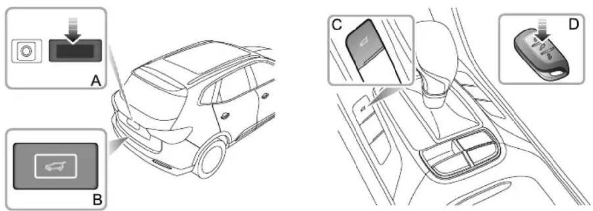
Electrictailgatecanbeopenedorclosedusingthefollowingmethods:
Open/Closefromoutside : WhenthevehicleisunlockedordmatchedkeyappearswithinImrangearoundthe tailgate,pressbuttonAtoopenthetailgate,pressbuttonBtoclose.
2Open/Closebysmartkey : WhenSTARTSTOPswitchisintheOFFposition,pressandholdthetailgatebutton Donthesmartkeytoautomaticallyopenorclosethetailgate.
3Open/Closefrominside : PressandholdthetailgateswitchbuttonConcentreconsoletoautomaticallyopenorclosethetailgate.(Ifthevehicleislockedfromtheoutside,switchbuttonCwillnotoperate.)
STARTING&DRIVING
Note: Incertain conditions where the vehicle has been stopped or parked on an extreme incline, that all gate may cannot be electrically opened or fully closed due to the change of centre-of-gravity position.
Ifthetailgatefailstofullyopentoit'spresetheight,orfully close,carryoutamanualoperationtoclosethetailgate, thiswillrestoretheelectrictailgateoperation.
Note: During manual operation of electric tailgate, avoid violent or rapid operation, failure to follow these instructions may result in damage to the power tailgatesystem.
Whenthetailgateisfullycloseditwilllockinpositionusing theelectriccatch.
Anti-pinchFunction
Whilstopeningthetailgate: Incaseswhereanobject that interferes with the tailgate operation is detected, the tailgate will stop opening and return to a safe angle automatically where the obstruction / scan beremoved.
Whilstclosingthetailgate:Incaseswhereanobject thatinterfereswiththetailgateoperationisdetected,
thetailgatewillstopclosingandreturntoasafeangle automaticallywheretheobstructionscanberemoved.
Note: If the anti-punch function has been activated multipletimes in a brief period, the system will suspend the electric opening/closing function for protection. In this situation, the gate can be fully closed once manually so astore set the function of electric tail gate.
Notetailgatfrequentlyperatem shortperiod,thesystemthermalprotectionmaybe triggered,causingtheelectricopening/closingfunction tobetemporarilyunavailabOperationwillbe suspendedforapresettimelimit.
SettingOpeningHeightforElectricTailgate
Userscansettheopeningheightofelectrictailgateas neededbyusingtheClosebuttononthailgateor InfotainmentscreenTheelectrictailgatecontrollerwill recordthenewopeningheight.
Not the setting value of opening height of the electric tail gatemust be between 40% and 100% of its total stroke.
STARTING&DRIVING
Settingmodel:
I Placethetailgatetodesiredsettingheight,andkeepit stationary.
2PressandholdtheClosebuttononthetailgatefora minimumof3seconds.Abuzzerwillsoundtoindicate thesuccessfulsetting.
Settingmode2:
T urnonthelnfotainmentsystem,entertheheightsetting interfaceforelectrictailgateunder"Setting"menu,and movetheightsettingslidertodesiredposition.
Note: If an electric tail gates system failure occurs, arelevant warning message "Power Liftgate System Fault" and icon will be displayed in the message centre of the instrument pack, please consult an MG Authorised Repairer.
T ailgateEmergencyOpen
Thetailgateemergencyopenswitchislocatedintheinner sideoftailgatelock.
Folddowntherearseattogainaccess,removetheblanking plug,insertasuitabletoolintotheopeningslotandrelease thetailgate lock.
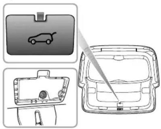
natural_image
Technical line drawings of a car interior frame with a car icon and a close-up view of the front panel (no text or symbols)STARTING&DRIVING
StartingandStoppingEngine
START/STOPSwitch
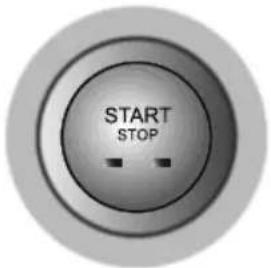
text_image
START STOPThekeylessSTART/STOPSwitchislocatedinthefasciato therightofthesteeringcolumn,itisapushbuttonstyle switch.T ooperatetheswitchthesmartkeymustbeinside thevehicle.
Theoperationalstatusdisplaysareasfollows:
IndicatorOff(OFF)
- If the switch has not been operated and there are no indicators illuminated, the powersystem is OFF. The power eats and electrically mirror on a main operational.
YellowLight(ACC)
- PressingtheSTART/STOPSwitchwithoutthefootbrake beingappliedwhilsttheswitchisintheOFFpositionwill placethevehicleintheACCstate,thiswillilluminate theyellowindicatorintheswitchbuttonTheACC positionallowsoperationofcertainancillariessuchas powerwindows.
GreenLight(ON/RUNNING)
- WhilstintheACCstate,pressingtheSTART/STOP Switchwithoutthefootbrakebeingappliedwillplace thesystemintheONstate,thegreenindicatorwill illuminataEwillowheemainingelectrical systemstooperate.
- PressingtheSTART/STOPSwitchwithParkorNeutral selected and the footbrake/clutchpedaappliedwillstart the enginehegreenindicatorwillilluminate. This indicates that all electrical systems will operate.
STARTING&DRIVING
Note: WhilstintheOFFstate, ifthedriverexitsthe vehicleleavingthesmartkeyinside, thehornwill soundonclosureofthedriver'sdoor. Subsequent re-openingofthedriver'sdoorwillcauseabuzzerto sound, awarningiconwillilluminateandawarning messagewillbedisplayedintheinstrumentpack messagecentretoidicatethathekeyisstillinthe car.
Note: ToremovethevehiclefromPark, thevehicle mustbeinanON/RUNNINGstateandthefootbrake applied.
If your carissubjecttostrongradiosignalsthekeyless entryandstartsystemsmaysufferfrominterference and notfunctioncorrectly.Pleaseseethe'AlternativeStarting' procedure.
StartingtheEngine
StartingtheEngine:
Ehsureallunnecessaryelectricaloadsareswitchedoff.
2 Ensure the parking brake is applied. (referto "Brake System" of this chapter)
3Forautotransmissionvehicles, EnsurePorNis selected and pressthebrakepedal (If the shift lever is in any other position, the engine cannot be started.)
4Formanualtransmissionvehicles,ensureneutralis selectedandtheclutchpedalisfullypressed.
PfesstheSTART/STOPSwitch(danotholdthebutton in,releaseimmediately).
6 The green indicator will illuminate.
ColdClimates
Intemperatures of -10°C cand below, engine cranking time will increase. It is essential that all unnecessary electrical equipment is switched off while cranking.
IMPORTANT
- If the vehicle will not enter a ON/RUNNING state, please check for any warning indicators or messages displayed in the instrument pack message centre. In extremely low temperatures please allow 5 minutes between power up attempts, if after 3 attempts the vehicle will not start please consult an MGA authorised repairer or breakdown service.
- DonotleavethepowersysteminanACCor ON/RUNNINGstateforlongperiodsoftime, excessiveuseofelectricalequipmentmayleadtoa dischargedbattery.
•Thevehicleisfittedwithananti-theftsystem. Independentlysourcedkeysmaynotallowvehiclestart theengine.Anynewkeyswillrequireprogramming usingthemanufacturerssoftware.
You casted with complex electronic control systeple, asesuththerdio transmissionorelectromagneticdevicesarekeptaway fromthesmartkeyandcentreconsolecubbyareas. Theymaycauseinterferenceandoperationalissues. Pleasesethe'AlternativeStarting'procedure.
AlternativeStartingProcedure
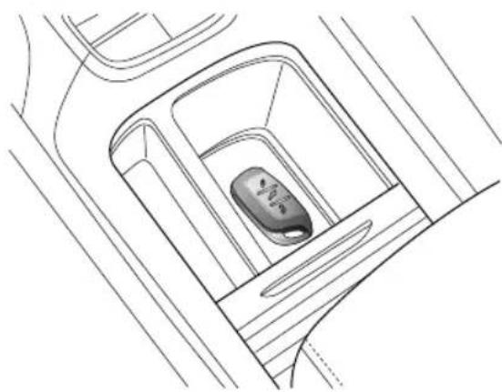
natural_image
Line drawing of a car interior showing the rearview and side profile of a vehicle (no text or symbols)theaikocateidarewherherarstrong radiosignalscausinginterferenceorthesmartkeybattery conditionisowpleaseuschefollowingtepsattempt tostartthecar:
I Placethesmartkeycentrallyinthecentreconsolecup holdercubbyboxwiththebuttonfacingupwards shownintheillustration.
STARTING&DRIVING
2EnsurePorNisselected, pressthebrake/clutch pedalandthenpressSTART/STOPSwitchtostartthe vehicle.
If the immobiliser cannot be released after the car has left the area of strong radiointerference or had the smart key battery replaced please consult an MGA authorised Repairer.
IMPORTANT
The Alternative Starting Procedures should only be required if the smart key battery is very low or flat. Oncethe vehicle has been removed from the area of excessive radio interferencethe key less entry and STOP-ST ART system should return on normal.
StoppingtheEngine
IAfterbringingthecartoahalt, ALWA YSmaintain brakepedalapplication.
2Applytheparkingbrake;
3Forvehicleswithautomatictransmission, placethe shiftleverinPposition;
4Forvehicleswithmanualtransmission,placetheshift leverinNposition;
5PressSTART/STOPSwitchtoshutdowntheengine.
Note: Should the engineering require to be shutdown in the case of an emergency, press and hold the START/STOP switch in excess of 4 seconds.
EconomicalandEnvironmentalDriving
Running-in
Theengine, transmission, brakesandtyresneedtimeto
'bed-in' and adjust to the demand so every day motoring.
During the first 900 miles, please heed the following advice soastoenhancethelong-term operation performance:
- Donotallowtheenginetoexceed3000rpminanygear orthevehiclespeedtoexceed72MPH.
- Donotoperateatfullthrottleorallowtheengineto labourinanygear.
- Donotdriveataconstantspeed(eitherhighspeedor lowspeed).
- Avoidheavybrakingwherepossible.
After900miles, enginespeedscanbegraduallyincreased.
EnvironmentProtection
Y ourvehiclehasbeendesignedwiththelatesttechnology inordertominimizetheenvironmentalimpactofexhaust emissions.
EconomicDrivingandMaintenance
The following a resomes suggestions on saving fuel and extending the life of the vehicles.
- Maintain the correctty repressure; insufficient air pressure will accelerate teryrewear and wasteful.
Drocarynnecessary(eighteloads will increasehenginloadsultinghighefuel consumption.
- Avoidengineidlingforextendedperiods.
- Maintainslowandsmoothaccelerationandavoidharsh acceleration;changetoahighergearassoonaspossible.
- Avoidlabouringtheengineoroverrunningchoose appropriategearsaccordingtotheroadconditions.
- Avoidcontinuousaccelerationdeceleration. stop-godrivingstylewillconsumemorefuel.
Avoid necessary stopping braking maintain steadyspeed and attempt to anticipate traffic lights.
Note: Keep an appropriate distance from other vehicle to avoid emergence braking and reduce brake pad wear.
STARTING&DRIVING
- Avoidtrafficcongestionandjamareasasmuchas possible.
- Anticipatingobstructionsandslowingdownwellin advance,avoidstheneedforunnecessaryacceleration andharshbraking.Asmoothdrivingstylenotonly reducesfuelconsumption,butcanreducetheemission ofnoxiousgases.
- Donotridethebrakepedal, this can cause premature wear, overheating and increased fuel consumption.
- Maintainanappropriatespeedonthehighway.Higher speedsusemorefuel.Appropriatespeedcansavefuel.
- Maintain the correct wheel alignment. Avoid collision with the kerband reduces speed on uneven road surfaces. Out of specification wheel alignment will not only lead to excessivity to rewear, but also increase the engine load and fuel consumption.
- Avoiddrivingonmudorbeaches. This will prevent corrosion of the vehicle underside.
- Maintain the vehicle in accordance with MG recommendations. Dirty air filters, oil etc., will reduce the engine's performance and raise fuel consumption.
Note: extend the life of all components and reducing operating costs, guided approved maintenance is needed.
Donostoptheenginestraighteftehighspeedlong ascentsortowingatrailer.Allowtheenginetoidlefor 20to100secondsdependingupondrivingloadsand conditions.Avoidhardaccelerationonacoldengine.
DrivinginSpecialEnvironment
DrivinginRainorSnow

Emergencybraking, accelerating and steering onslipperyroadswillreducethevehicle's handlingperformanceandgrip.
- Whenrainingthewindowsmayfog,reducingvisibility (UsetheAir-conditioningdemistfunction).
- Gripwillbereducedwhenitrains,sopleasereduce speeddrivecarefully.
- Reducespeedwhenitrains.
- Avoiddrivinginhighspeed, because the film of water between the yres and the road will affect the steering and braking performance.
DrivingthroughWater
Avoiddrivingthroughfloodsafterheavyrain,whichmay leadtoseriousdamagetothevehicle.
STARTING&DRIVING
CatalyticConverterandParticulate Filter

Thetemperaturesofexhaustsystemsthat containparticulatefiltersandcatalytic converterscanbeextremelyhigh,DONOT parkongroundwherecombustiblematerials suchasdrygrassorleavescouldcomeinto contactwiththeexhaustsystem-indry weatherafirecouldresult.
Theexhaustsystemincorporatesacatalyticconverter andparticulatefilter,whichconvertspoisonousexhaust emissionsfromtheengineintoenvironmentallyless harmfulgases.Catalyticconverterandparticulatefilterare easilydamagedthroughimproperuse,pleaseobservethe followingprecautionstominimisethechanceofaccidental damage.
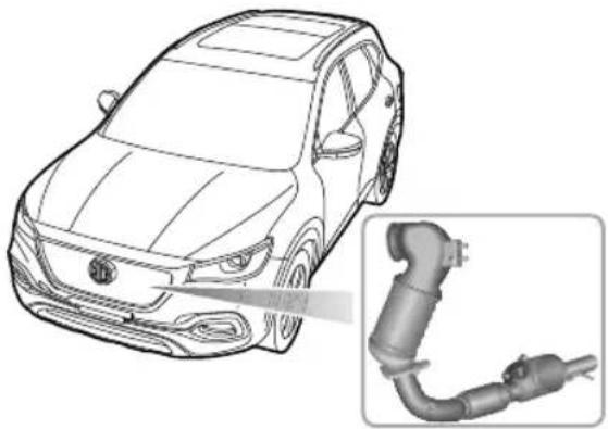
natural_image
Line drawing of a car with an inset showing a connected electrical plug (no text or symbols present)Fuel
•UseONLYfuelrecommendedforyourcar.
- Neverallowthecartorunoutoffuel—thiscould causeenginemisfireandseriousdamagetothecatalytic converterandparticulatefilter.
STARTING&DRIVING
Starting
Payattentiontothefollowingswhenstartingtheengine:
- Donotcontinuetooperatethestarterafterafewfailed attempts;seekMGAuthorisedRepairer.
- Donotoperatethestarterifanenginemisfireis suspectedanddonotattempttoclearamisfireby pressingtheacceleratorpedal.
- Donotattempttopushortowstartthecar.
Driving
Please pay attention to the following conditions:
- Donotoverloadorexcessively'rev'ofengine.
- Donotstoptheenginewhenthecarisinmotionwith Doragearselected.
- SeekMGAuthorised Repairerifyouthinkyourcar'soil consumptionisabnormal.
•lfamisfireissuspected,orthecarlackspowerwhile driving,providedtheenginehasreacheditsnormal operatingtemperature,itmaybedrivenSLOWLY(at riskofcatalystandparticulatefilterdamage)toanMG AuthorisedRepairer.
- Donotdriveonterrainlikelytosubjecttheunderside ofthecartoheavyimpacts.
Note: Anyenginemisfire, lossofengineperformance orenginerun-on, could seriously damagethecatalytic converterand particulatefilter. Regular maintenance must be carried out in accordance with the schedule specified in the 'ServicePortfolio'. Anymodification to engine without being authorised is prohibited.
EngineOils
Recommendethonlyithaneethe
manufacturersspecificationareused.Useofoilsthat donotmeetthemanufacturersspecificationscan damagetheparticulatefilter,forexamplelowSAPSoils canaffectparticulatefilterashcapacity.
STARTING&DRIVING
FuelSystem
FuelRequirements

Useonlytherecommendedfuelwhich meetsnationalstandard!Seriousdamage tothecatalyticconverter,areductionin enginepower/torqueandincreaseinfuel consumptionwilloccurifthewrongfuelis used.
Usethefuelrecommendedbythemanufacturer.See"Main ParametersofEngine"in"TechnicalData"chapter.
Ifalowergradeoffuelisused,anengineknocking noisemayoccur,pleaseusetherecommendedorabove gradefuelassoonaspossibletheengineknocking noiseisstillnoticeableafterusingtherecommendedor abovegradefuel,pleasecontactMGAuthorisedRepairer immediately.Itispermittedthatfuelcanbeusedwitha higheroctaneratingthanthatrequiredbytheengine,but itisnotadvantageousforengineoutputpowerandfuel consumption.
SafetyPrecautionsinaFuelFillingStation

Vehicfoughseleighflammable and, inconfinedspaces, are also extremely explosive.
Alwaystakecarewhenrefueling:
Switchofftheengine.
Donotsmokeoruseanakedflame.
Donotuseamobilephone.
Avoidspillingfuel.
Donotoverfillthetank.
FuelFiller
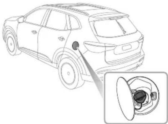
natural_image
Line drawing of a car with a sensor or dial inserted, showing the engine and internal components (no text or symbols)FuelFillerFlap
Thefuelfillerflapislocatedontherearleft-handwing.lts lockisconnectedwithcentralcontroldoorlocksystem. Presstherightsideoftheflaptoopenitwhenthedooris unlocked.
Note: The fuelfillerflapwillonlybelockedwhenthe doorsarelocked.
FuelFillerCap
Slowlyunscrewthefillercapanti-clockwiseandallowany pressureinsidethetanktoescape,beforeeremovingthe cap.
Afterrefueling,tightenthefillercapclockwiseuntilyou hear I "click"sound.
Ifthefuelfillercapisleftlooseorthesealisdamagedthe enginemalfunctionwarninglightintheinstrumentpack willilluminate,pleasesecurethecaporseal.Ifthelamp remainsilluminateconsultanMGAuthorisedRepairer.
Refueling
Donotfullyfillthetankifthevehicleistobeparkedin directsunlight,orhighambienttemperature-expansionof thefuelcouldcausespillage.Thefuelfillertubeisdesigned toacceptanarrow,longfillernozzle.Thereisacover atthefillerneck,byinsertingthefillernozzlethoroughly beforefuelfilling,thecovercanbefullyopened.
Starttheengineafterfuelfilling.Afterrefueling,if theengine runsunevenly,switchoffandseekanMG
STARTING&DRIVING
AuthorisedRepairerbeforeattemptingtorestartthe engine.
ManualT transmission\*
GearShiftLever
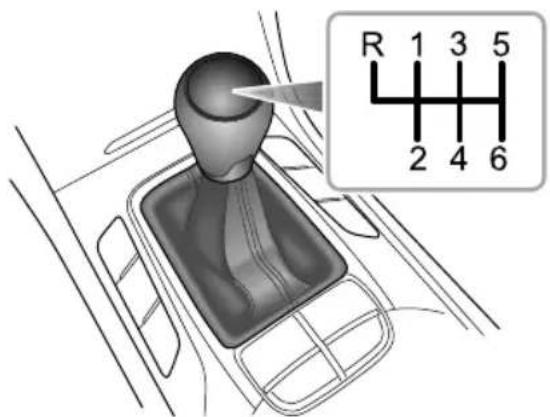
text_image
R 1 3 5 2 4 6Themanualtransmissionisa6-speedtransmissionwith 7gears, which are: 1st, 2nd, 3rd, 4th, 5th, 6th and R (Reverse) respectively. All gearshavesynchromesh.
Precautionswhiledriving:
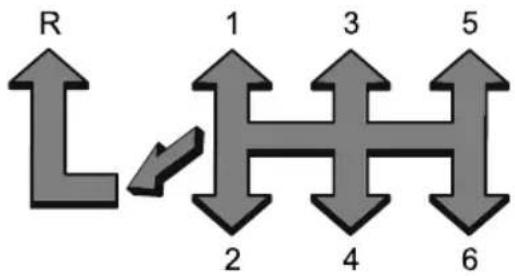
flowchart
graph TD
    R --> L
    L --> 1
    1 --> H
    H --> 3
    3 --> 5
    5 --> 6
    2 --> H
    4 --> H
    6 --> H
I WhenselectingReversegear, you must ensure that the vehicle is completely instationery wait for a moment and then fully press the clutchpedal, from the N position press the lever down and push it leftward, then push it forward into the R position, slowly release the clutchpedal to complete the gear shift.
2 Donotrestyourhandoegearshiftlever
whiledriving-pressurefromyourhandmaycause
prematureweartothegearsselectormechanism.
Danotrestyoufoortheclutchpedalwhendriving -excessiveweartotheclutchwillresult.
STARTING&DRIVING
4Donotholdthecarstationaryonahillbyslippingthe clutch. This will wear out the clutch.
GearDisplayandGearShiftIndications
WhenthevehicleisstationaryandNgearisselected,the informationcentrewilldisplayN.
WhenReversegearisselected, the informationcentrewill displayR.
Whenthevehicleisinmotionandtheclutchpedalis fullyreleased,iftheselectedgearisinappropriate,the informationcentrewilldisplaythetargetgear(1-6)andan Up/Downarrowindicatingtothedrivertoeitherupshift ordownshiftttothedisplayedgearwhendrivingconditions permit.
Note: Gearshiftindicationsareadvisoryandfor informationonly. Gearshiftoperationsshouldbe carriedoutonthepremisethatyourownsafetyis guaranteedandthetrafficregulationsareobserved.
DualClutchAutomaticT transmission\*
Instructions
The following information is very important, pleaseread carefully before use:
- Beforestartingtheengine,ensurethedoorsareclosed, placethegearleverinPorNposition,ensurethefoot brakeispressedandparkingbrakeisapplied.
• After the engine has started, ensure the footbrake and electronic parking brake are applied, shift the lever to there required gear.
-Releasetheelectronicparkingbrakesystemandhold thefootbrakeuntilyouarereadytomanoeuvrethe vehicle.Oncethefootbrakeisreleased,onflatroad, thevehiclewillautomaticallystartoffataslowspeed withoutapplicationoftheaccelerator.
•DuringdrivingDONOTcoastinneutral, it could damage the transmission or cause an accident.
ElectronicShiftLever
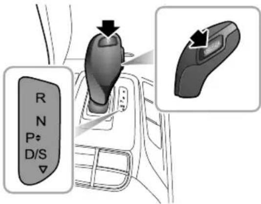
text_image
R N P D/S ▼Thedualclutchautomatictransmissionisa7-speed transmission.
Note: The highlighted letter or number in the information centre indicates these selected gear or mode.
TheElectronicShiftLeverfeaturesaP(Park)buttononthe topandanUNLOCKbuttonontheside.
STARTING&DRIVING
OperationofElectronicShiftLever

Unless necessary, it is not recommended to press UNLOCK button during gear shifting. This may allow inadvertent gear lever movement and incorrect gear selection causing possible damage.
TheElectronicShiftLeverdefaultstothemiddle steady-state. Theforwardandbackwardpositions are non-steadystates.
Note: T omoveoutofPortomoveintoReverse, the footbrakemustbedepressedandtheUNLOCKbutton mustbepressedsimultaneously.
T ransmissionGears
•P:Park
Depressthefootbrakeandwaituntilthevehicleis stationary,presstheButtontenterGear.
In this position the transmission mechanically locked. Engaging only whether the vehicle stationary and the EPB system is applied.
Toparkhevehicleonslope, depressthfoot brake, applytheEPBsystemhenshifttoP position.
When the vehicle is stationary operating the start/stop switch the OFF position will cause the vehicle center position automatically.
Whenthevehicleisstationary,ifthefootbrakeis notapplied;thdriver'seabelreleased and thedriver'sdooropened;thevehiclevilenteP positionautomatically.
•R:Reverse
Depressthefootbrake, pressandholdtheUNLOCK buttonpushtheelectricshiftleverforwardtothe end,thevehiclewillenterReverse.
Selecthigeaonlywherthevehiclestationary.
•N:Neutral
WheninPark, depress the footbrake, press and hold the UNLOCK button to the electron is he lever forward toward the steady state position, the vehicle will ente Neutral.
WhilstD/Sisselected, pushthe electronic shift lever forward to the first non-steady state position, the vehicle will enter Neutral.
InReverse, pull the electronic shift lever backward to the first non-steady state position, the vehicle will enter Neutral.
Select this gear when the vehicle is stationary and the engine running at idlespeed for along time (for example, waiting traffic lights).
•D:Drive
WhilstinPark, depress the footbrake, press and hold the UNLOCK button, pull the electronic shift lever backward to the end, the vehicle will enter Drive.
InR\N\S, pull the electronic shift lever backward to the end, the vehicle will enter Drive.
Itisusedfornormaldrivingandwillallowautomatic selectionof7forwardgearsdependingonvehiclespeed andacceleratorposition.
InDrive, the automatic transmission will enter standard mode and the information centredisplays "D".
•S:SportMode
InDrive, pull the electronic shift lever backward, the vehicle will enter Sport mode and the information centredisplays "S".
WhilstinSportmode, the transmissionupshiftslater, soastomakefulluseofthepowerreservesofthe engine. When more acceleration is required, select Sportmodebupleasnotethathéuetonsumption will be increased.
T oexitSportmode, pulltheelectronicshiftlever backward.
GearshiftSpeed
Selecting Dor Swill allow the transmission controller to carry out gear shift whilst considering number factors including engines speed vehicles speed and accelerator position. Light accelerator pedal application will result in age - change at low speeds, larger pedal applications will resulting in gear - changes at high speeds.
STARTING&DRIVING
Kick-down

The drivewheelsmayskidwhenkick-downis activatedonroadsurfaceswithlowadhesion, this may lead to the vehicles sliding out of control.
With Dor S gear selected, pressing the accelerator pedal all the way down in onemotion (also known as Kick-down) will provide better acceleration performance during overtaking. Under certain conditions, it will allow the transmission to shift to lower gear immediately, and provide fast acceleration. Onc the accelerator pedal is released, it will resume suitable normal gear (based on the vehicles speed and the position of the accelerator pedal).
ManualMode \*
WhilstSportmodeisselected, the paddleswitcheslocated onthesteeringwheelcanbetoggledtoenableManual mode. The current gear position (1 to 7) will be displayed in the information centre.
Pressthe"+"paddleswitchtoupshifttothenextavailable highgearandpressthe"-"paddleswitchtodownshiftto thenextavailablelowgear.
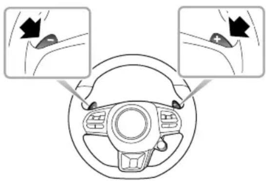
text_image
Diagram showing car steering wheel with two close-up views of the steering wheel and a black arrow indicating direction of movement.WhilstinManualmode,ifthedrivermakesanunreasonable gearselection,requestsanupshiftduringlowengine speeds,orrequestsadownshiftduringhighenginespeeds, thetransmissionwillnotrespondandwillremain in thecurrentgear.Ifthevehicleisdrivenandtheengine
speedfallsbelowapresetthresholdincertainingears,the transmissionwillautomaticallyshiftdowntothenextgear toavoidenginestalling;whenthevehicleaccelerates,if theenginespeedexceedsapresetlimit,thetransmission willautomaticallyshiftuptothenextgeartoprotectthe engine.
WhilstinManualmode,iftheselectedgearis inappropriate,theinformationcentrewillprovidegearshift indications.AnUp/Downarrowisdisplayedabove/under thefigure,indicatingtothedrivertoeitherupshiftor downshiftwhendrivingconditionspermit.
Not Gearshiftindicationsareadvisoryandfor informationon Gearshiftoperationsshouldbe carriedoutonthepremisethatyouownsafetyis guaranteedandthetrafficregulationsareobserved.
TexManuahodpthelectronishifever backward.
ProtectionMode

Whenparking, drivethevehicletoasafe areaonthepremisethatyourownsafety isguaranteedandthetrafficregulationsare observed.
OverheatingteAtiomatic
Transmission
Startingofffrequentlyathighambienttemperaturesmay causehightransmissiontemperatures.Inordertoprevent damage,thesystemwillperformanoverheatingprotection routine,theinformationcentrewilldisplaytherelevant icomnMessagesaccompaniebyaudibalarm.
Dependingontheseverityoftheoverheating,thewarning messagesmayrequestthedriverto"IncreaseSpeedor StopSafely",or"StopSafely"(ifcircumstancesallow).
With the transmission overheating, the warning message showing "Stop Safely" and the engine emission malfunction indicator lampon, please parks safely and shift the lever to Pto allow the transmission to cool, the information centre will display "Please Wait during this time the
STARTING&DRIVING
enginecanbeswitchedoff,vehicleexitedandlocked.Only whenthetransmissiontemperaturehasdecreasedandthe informationcentredisplays"ReadyforDriveAway"can thevehiclestartoff.
If the driver adhered to the instructions displayed in the information centre for 20 minutes and the warnings havenotalteredord disappeared, seek an MGA authorised Repairer immediately.
LimpMode
WhensomefailuresoccurthetransmissionwillenterLimp Modeandwillonlyfunctioninsomegears,insomecasesit mayfailtoReverse,duringthistimetheinformationcentre willdisplaytheengineemissionmalfunctionindicatorlamp. SeekanMGAuthorisedRepairerimmediately.
Note: Inlimpmode, Manualmode is disabled.
SevereFunctionalMalfunctionofAutomatic
T transmission
Sometransmissionmalfunctionswillcausetheengine emissionmalfunctionwarninglamptoilluminate.T o
protectthetransmissionthesystemmaycutoffingine powetotheclutchthevehiclecannotbedriven. SeekanMGAuthorisedRepairerimmediately.
MalfunctionofElectronicShiftSystem
Whensomemalfunctionsofelectronicshiftsystemoccur, theinformationcentreindicates"BackupforE-shifteris ActivatedConsultHandbookAthistimehgears canstillbeshiftednormally.
Whensomeseverfunctionalmalfunctionsofelectronic shiftsystemoccur ,thePbuttonindicatorontheeelectronic shiftleverflashesandtheinformationcentreindicates"EP". Atthistime,thegearscannotbeshifted.Fordrivingsafety, whenthevehiclespeedislowerthanacertainvalue,the powersystemwillforciblycutoffthepowertransmission, andthevehiclewillnotbeabletodrive!
Incaseofthebovesituations,seekanMGAuthorised Repairerimmediately.
STARTING&DRIVING
DrivingMode \*

Switchingthedrivingmodewhenthevehicle isinmotioncandivertdriver'sattentionfrom roadconditions, thisoperationcanonlybe performedwhensafetypermits.
The vehicle is equipped with a Driving Modes switch in the centre console, operating this switch allowed the driverto select their preferred driving mode.

text_image
MODEWhenthevehicleisinmotionorstationary,pressingthe drivingmodeselectionswitch(MODE)oncewillcycle throughtheavailabledrivingmodes:
IECOMode
The vehicle is placed in "lowenergy" usage state and will provide optimum fuel consumption and emissions.
2NORMALMode
The vehicle enters balanced tuning state for daily driving.
3SPORTMode
Provided driver with amoredynamic driving experience, suitable for sporty driving style.
4CUSTOMMode
AfterselectingCUSTOMmode, the driver can personalize system using a fotainment display when the vehicle is stationary.
Whenthestart/stopswitchisswitchedoffall CUSTOMsettingsaresaved.
STARTING&DRIVING
Note: WhentheelectronicshiftleverisinD/Sposition, pullitbackwardtoenterorexitSPORTmode.
SUPERSPORTMode
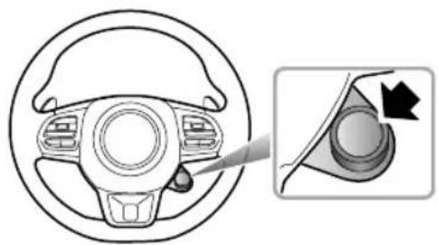
natural_image
Diagram of a car steering wheel and dashboard with an inset showing the wheel's rotation (no text or symbols)PressingtheSUPERSPORTbuttononthesteeringwheel caninstantlyenterorexitSUPERSPORTmode.
WhilstinSUPERSPORTmode,thereisachangeto ambientlightingforsomemodels,whichissuitablefor intensifiedriving.
Note: Theentry/exitofthismodecanonlybeachieved byusingtheSUPERSPORTbutton,afterexitingSuper Sport,thevehiclewillreturntothepreviousselected drivingmode.
Whenswitchingthedrivingmode,theinstrumentcluster willdisplayacorrespondingmessage(ECO,NORMAL, SPORT ,CUSTOM* andSUPERSPORT).
Whenthestart/stopswitchisswitchedoff,thevehiclewill switchbacktoNORMALmodebydefault.
Indifferentdrivingmodes, thepowerdelivery, steeringand airconditioningsystemvaries, pleaserefertothetable below.
| ModePowertrain | EPSHVAC | ||
| ECO | Eco | Comfort | Eco |
| NORMAL | NormalNormal | Normal | |
| SpSPORT | Normal | ||
| SUPER SPORT | SportSport | Normal | |
| CUSTOM* | CustomCustomCustom | ||
AmbientLighting \*
Ambientlightingcanbelinkedwiththedrivingmode,it willswitchbetweendifferentcoloursindifferentdriving modes.WhentheambientlightingisintheCUSTOMstate, itwillnotbeaffectedbythedrivingmode.Forthesetting ofambientlighting,pleaserefertotheinfotainmentdisplay.
PowertrainSystem
The transmissionchangestheshiftpatternaccording to the set driving mode. Whenthe powertrainisin ECO, NORMALandSPORTmode, the instrument cluster will display "E", "D" and "S" respectively.
Not powertrain system development, sufficient utility is not NORMAL mode automatically.
SteeringSystem
Thesteeringsystemappropriatelyincreasesordecreases thessisoutputaccordingthe-drivingnode.
The drive effort that steering he is while altered according to the set mode for the conditions for switching the steering feel, pleasereferto "Steering System" in "Instruments and Controls" chapter.
Not the electron is teering system develops faultors suffers a failure, it will enter NORMAL mode automatically.
AirConditioningSystem
WhilsEConodetheconditioningysteris switchedonitwilloperateinanenergysavingmode. This reducespowerconsumptionandallowsmorepowertobe directedtothevehicle.
STARTING&DRIVING
BrakeSystem
FootBrake
Foradded safety, the hydraulic braking system operates through dual circuits. If one circuit should fail, the other will continue of function, but greater pedal pressure will be needed, the brake pedal travel will be increased, and the stopping distances will be increased. In the event of a brake failure where only one circuit is operational, the car should be brought to an halt as soon as a traffic condition safely allow. DONOT continued driving-seekan MGA authorised Repairer.
ServoAssistance
Thebrakingsystemisservoassisted,alwaysbeawareof thefollowingsduringtheoperation:
- Theservoassistancefunctionswiththeengine running only.Neverallowthecartofreewheelwiththeengine turnedoff.
• If the engines should stop for any reason while driving, bring the cartoahaltas quickly a traffic conditions safely allow, and donot pump the brake pedal as the
brakingsystemwillloseanyremainingservoassistance. Oncetheenginehasstopped, it will lose any remaining servoassistance, uses suitable for ceto apply the brake pedal to stop the cars safely in the current traffic conditions. Contact an MGA authorised Repairer.
•Theefficiencyofthebrakeservoboostercanbe affectedbynumerousconditions,suchasthechange ofbarometricpressure.Theseconditionscouldresult inextraforcerequiredtooperatethebrakepedalto stopthecar.
WetConditions
Drivingthroughwaterorheavyrainmayadverselyaffect brakingefficientTheC(StabilityControlSystem) includesaBrakeDiscWipingfunctionwhichisactivated whentewindscreenwipersareused.However,always keepsafedistancefromothervehiclesandintermittently applythebrakepedalinconditionswherethewipersare notused.
ElectronicBrakeForceDistribution(EBD)
Y ourcarisequippedwithEBD,which,inordertomaintain brakingefficiency,distributesbrakingforcesbetweenfront andrearwheels,underallloadconditions.
EBDintegratesamonitoringsystem. Themonitoring systemislinkedtothebrakesystemmalfunctionindicator lampontheinstrumentpack. Referto "WarningLights and Indicators" in "InstrumentsandControls" chapter.
If the indicator lampilluminates while driving, or remains illuminated after the start/stop switchisturned on (ON/RUNNING position), it indicates there is a failure with the braking system, and EBD may be inoperative. In such case, stop the car as soon as safety permits and seek an MG Authorised Repairer immediately. DONOT drive the car with the braking system malfunction indicator lampilluminated.
ElectronicBrakeAssistance(EBA)
Y ourcarisequippedwithElectronicBrakeAssist,which reactstothespeedatwhichthebrakepedalisapplied.If, inremergencysituationthebrakesareappliedafterthan thelimitssetwithinthesystem,thenfullABSapplicationis appliedtobringthecartostopintheshortestpossible distance.
HillHoldControl(HHC)

HHChaslimitationswhensubjecttoadverse conditionssuchaswetoicysurfaceand steepslopes.

HHCisnotasubstituteforparkingbrake applicationwhencarryingoutahillstart. DONOTexitthevehiclewithonlyHHC applied,itmayleadtoaseriousaccident whenHHCreleases.

Thecarmayrollif pull-away is not achieved immediately after releasing the brake pedal. Always ensure the brake pedal is pressed for parking brake applied until drive is taken up.

Alwaysensurethebrakepedalispressedor electronicparkingbrakeapplieduntildriveis takenup.
STARTING&DRIVING

Firmapplicationofthebrakepedalwhen stoppingisrequiredbyHHCtogenerate sufficientbrakepressureotomainhold.
HillHoldControl(HHC)isacomfortfunction.Itworks oninclineswhenthecardetectsithascometoa'ststand stillstatus'.Oncetheclutchpedalhasbeenpresseddown (MT)orinD/Rgear(A T)andthebrakepedalreleased, thevehiclewillmaintainpressureinthebrakingsystemfor 1 \~ 2seconds.Afterthis,theHillHoldwillrelease.HHC assiststhedriverby'holding'thevehicleduringhillstarts.
The following conditions must be fulfilled to activate HHC:
- Thedriver'sdoorisclosedandthedriverseatbeltis fastened.
• The vehicle is stopped on a slope in excess of 4% and form more than 2 seconds.
•SCSisfaultfree.
•EPBisreleasedandfaultfree. - Clutchpedalispressed(MT), orinD/Rgear(AT).
•Engineisrunning. - Sufficientbrakepedalapplicationforcehasbeenapplied.
If the driver releases the brake pedalonahill, HHC with a tibrak pressur for \~ second vehicle fail stop pull away in 1 \~ 2 seconds, the braking will automatically release, the vehicle may begin to roll. In this case, the brake pedal must be pressed immediately.
Note: HHCisavailableinbothforwardandbackward directionswhenpullingawayonuphillslopes.
Note: If the information centre in the instrument pack is play the message "HillHold Unavailable", indicate that the hold on train invalid is not properly enabled, please seek an MGA authorised Repairerurgently.
Note: HHC cannot overcome physical limitations. DO NOT solely rely on HHC.
AutoHold

The autohold function cannot guarantee the stability of the vehicle when starting for braking on hills especially on slippery or icy surfaces.
STARTING&DRIVING

Whenautoholdstopsthevehicleforreasons suchasenginecutout,releasingtheseat beltorpressingtheautoholdswitch,the electronicparkingbrakeisapplied.It cannotbeguaranteedthatthevehiclewill bestabilisedinallcases. Forexample,the rearwheelsareonaslipperyroadsurface, orthevehicleinclineistoogreat(largerthan 20%).Pleasemakesurethatthevehicleis safelystabilisedpriortoexiting.

DONOTtakeanyextrariskshwhendriving duetothefactthevehicleisfittedwith additionalconveniencefunctions. Thedriver shouldpayfullattentionandobservethe surroundingsevenifthevehicleisequipped withautoholdsystem.

DONOTleavethevehiclewhentheengine isoperatingandtheautoholdisactive.

Autohold cannot guarantee the electronic parking brake operation in all cases where the engine is stopped. Please ensure the electronic parking brake applied and the vehicle is stabilized prior to exiting the vehicle.

The autoholdfunctions should be switched off during the use of automatic car washes, the electronic parking brakemays suddenly apply and caused damage to the vehicle.
If the vehicle is required to stop frequently for a length of time (such as traffic lights, traffic queues or stops / start), and the engine is running, the auto holds system assists in stabilising the vehicle, enabling you to remove your foot from the brake pedal when the vehicle is stationary and the Auto Hold active.
Autoholdhas3mainstates:
Off:FunctioninOffstate.
Standby:FunctioninStandbystate.Thefunctionis activebutthevehiclehasnotstoppeOncethe
STARTING&DRIVING
vehiclehasstopped, and all other conditions are met, the system will automatically select Park.
3Parking:FunctioninParkedstate.Inthisstatethe green (P) indicatorintheinstrumentpackilluminates.
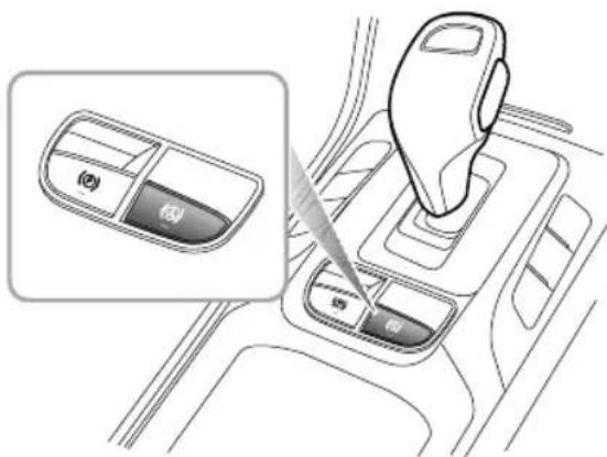
text_image
Diagram showing car interior with labeled dashboard controls and a zoomed-in view of the dashboard panelWiththedriver'sseatbeltfastened, the door closed and the engineer running, press the autohold switch to switch the autohold function from Off to Stand by state.
Withthebrakepedalfirmlypressedandthevehicle completelystopped,theautoholdfunctionwillswitch fromtheStandbystatetotheParkingstate.
WhentheautoholdisintheParkingstate,engaging forwardorreversegearandpressingtheacceleratorwill automaticallyreleasetheautoholdfunction.
Insomecircumstancesuchasreleasingtheseatbelt, switchingofftheengineorremainingstaticforalength oftimeitwillresultinthevehicleexitingtheautohold Parkingstate.Atthistimetheelectronicparkingbrake willremainappliedandwillrequirethedrivertorelease itusingtheswitch.
Note: With the brake pressed, presstheswitch to switch off the autohold function, but the electronic parking brakewill not be applied.
Note: It is recommended to turn off the autohold function when reversing into the garage.
Note: For MT models, pressthe accelerator pedal to startoff.
HillDescentControl(HDC)

TheHDCsystemisonlyanauxiliary function. Ithaslimitationswhensubjectto adverseconditionssuchaswetoricysurfaces andsteepslopes. TheHDCsystemcannot overcomethelawsofphysics, alwaysensure thatthevehicleisdrivendownsteepslopes atlowspeeds.

EvenwhentheHDCsystemisswitchedon, thedrivermustalwayspaycloseattention tothedrivingstateofthevehicle, andtake activecontrolwhennecessary.Incertain cases,HDCmaybesuspendedorswitched offtemporarily.

Duringsomedrivingconditionsdownhill surfaces(egivingdownaslopewith highspeed,theslopeislessthan 10%,etc.), HDCisinoperative,thedrivermustmaintain controlofthevehicleatalltimesanduse brakeapplicationstoensuresafety.
TheHDCsystemisanauxiliaryfunctionspeciallydesigned fordrivingacutdownhighradientSystem reduces the speed by applying brake force, thus assisting the driver to drive on acutdownhillsurfaces with low speeds.
PleaseDONOTusethisfunctionwhendrivingonthe ordinaryroads.
When the HDC is working, the brakesystem may generate strong vibration or noise. It is normal during the operation of HDC.
NotDuringtheoperationofhilldescentcontrol (HDC)system, pleasedonotswitchtheshiftleverto "N"position.SuchoperationmaydeactivatetheHDC function.
STARTING&DRIVING
HDCSystemOn/Off
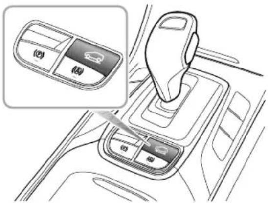
natural_image
Interior view of a car gear shift lever with control panel and mode dial (no text or symbols)Whenthestart/stopswitchisplacedinON/RUNNING position,HDCsystemdefaultstooff.Pressthebuttonto turnon/offHDCsystem.
Normally, HDCsystemhasfourstatesasfollows: I Standby: PresstheHDCswitchtosetthesysteminto standbymode, thegreenHDCwarninglampinthe instrumentpackwillilluminate.
2Operating: whilstinStandbymode, when the vehicle is drivendownanacutegradient, if the accelerator and/or brake pedals are not pressed and if the vehicle speed is higher than 5 mph (8 km/h) but less than 22 mph (35 km/h), the HDC system will automatically enter the operating state. In this case, the HDC warning lamp in the instrument pack flashes green, this may be accompanied by the working noise of the brake system. The HDC system will attempt to maintain the vehicle at the current speed. After the driver presses the accelerator or brake pedal, and the vehicles speed is still within the range of 5 \~ 22 mph (8 \~ 35 km/h), the HDC system will control the targets speed at the latest currents speed.
Temporary deactivation press accelerator brakepedal beyond apreset limit whilst in operating mode and the HDC system will temporarily suspend operation.
4Off:presstheHDCswitch(OFF)toswitchthesystem OFF ,thegreenHDCwarninglampintheinstrument packwillextinguish.
Note: For MT models, HDC function can be applied only in 1st gear.
Note: Whenthevehicleturnsatafastspeedwhilston anincline, the HDCsystemmayswitchfromStandby toOperatingmode.
Note: During HDC system operation the braking system will automatically pressurise and maintain pressure. Operation of the brake pedal during this phase may result in a kickback's sensation through the pedal. This is normal for HDC operation.
HDCON/MalfunctionIndicatorLamp
Referto"WarningLightsandIndicators"in"Instruments andControls"chapter.
Anti-lockBrakeSystem(ABS)

ABScannotovercomethephysical limitationsofstoppingthecarintooshort adistance,corneringattoohighaspeed,or thedangerofaquaplaning,i.e.wherealayer ofwaterpreventsadequatecontactbetween thetyresandtheroadsurface.
The purpose of the ABSistopreventthewheels from lockingwhilebraking, thereby enabling the drivertoretain steering control of the car.
The fact that a car is fitted with ABS must never tempt the driver into taking risk that could affect this/hersafety or other roads and systems remains the driver's responsibility to drivewith innormalsafety margins, having due consideration for prevailing weather and traffic conditions.
UnderormakeringconditionABSilbe activated. However, oncethebrakingforceexceedsthe availableadhesionbetweenthetyresandtheroadsurface, therebycausingthewheelstolock, ABSwillautomatically
STARTING&DRIVING
comeintooperation. This will berecognisable by a rapid pulsation felt through the brake pedal.
BrakinginanEmergency

DONOTpumpthebrakepedalatanytime; thiswillinterrupttheoperationofABSand mayincreasethebrakingdistance.
Ifanemergencysituationoccurs, the drivers should apply full braking effort to even when the roads surface is slippery. ABS will ensure that the wheels donotlock and that the car is brought to a halt in the shortest distance for the prevailing roads surface conditions.
Note: Onsoftsurfacesuchaspowderysnow, sand orgravel, the braking distance produced by the ABS system may be greater than that for an on-ABS system, even improved steering would be experienced. This is because natural action of locked wheels on soft surfaces is to build up a wedge of material in front of the yrecontact patch. This effect assists the carto stop.
Nomatterhowhardyoubrake,youarestillableto continuesteeringthevehicleasnormal.
IMPORTANT
ABScannotreliablymakeupforthedriver's mis-operationorlackofexperience.
ABSMalfunctionIndicatorLamp
Referto"WarningLightsandIndicators"in"Instruments andControls"chapter.
Note: Thenormal(non-ABS)brakingsystemremains fullyoperationalandisnotaffectedbypartialor fulllossofABS. However, the brakingdistances may increase.
ActiveRolloverProtection(ARP)

The ARP system cannot overcomethelawsof physics. It is a driver aid to assist the stability of the vehicle and under extreme conditions. It is not guarantee that the car will not roll over.
STARTING&DRIVING
Incaseswherethevehiclehasahighcentreofmass,rapid orexcessivedualdirectionlanechangingmaycreatea rollcondition.ARPmayusethebrakingsystemtoapply certainbrakestotryandcorrecttheconditionandassist inpreventingrollover.
Note: During ARP application the steering characteristic of the vehicle may be noticeably different from normal.
EmergencyBrakingHazardWarningLights ControlSystem(HAZ)
If the vehicle is a travelling high speed and the driver makes an emergency braking manoeuvre, the system will automatically flash the brake dampsmind the following drivers, thereby effectively reducing the risk of rear-end collision accidents.
Note: If the hazard warning lights are being operated manually, this suspend the HAZ function.
Whentheemergencybrakingmanoeuvreisexited(no severedecelerationdetected)thenthefunctionwillbe switchedoffafterafewseconds.
Note: A sheaspeed drops below 6 mph (10 km/h) and the system no longer flashesthebrakelamps, the hazard warning lamp willilluminate automatically. Short press the hazard warning lamp switch or increase yourspeed to above 12 mph (20 km/h) for 5 stoswitch off the hazard warning lamps.
STARTING&DRIVING
ElectronicParkingBrake(EPB)

IntheeventofEPBmalfunctionwhereEPB releaseisnotpossible,pleaseconsultanMG AuthorisedRepairerinordertocarryoutan emergencymanualreleaseoftheparking brake.
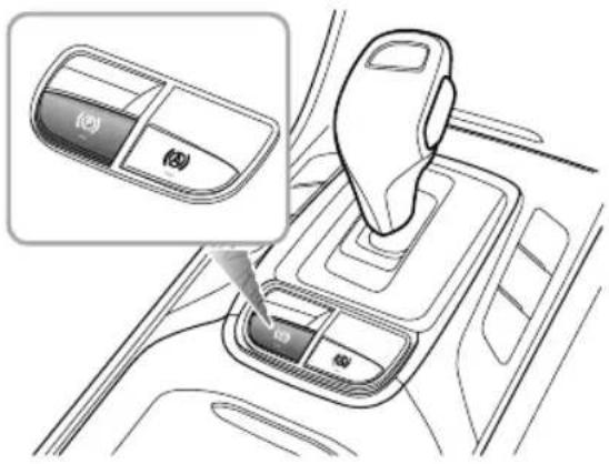
text_image
(A) (B)ApplyingtheEPB
While the vehicle is stationary, the EPB can be applied. Ensure the EPB is applied every time the vehicle is left for parked.
• PulltheEPBswitchupwarduntiltheindicatorintheEPB switchilluminates.
• Simultaneously, the EPB indicator will illuminate in the instrument pack. When the indicator in the EPB switch and the EPB indicator are illuminated, it indicates that the EPB is applied.
- If the EPB malfunction indicator lamp (F) in the instrument pack remains on, it indicates that a fault has been detected. Please contact an MGA authorised Repairer immediately.
Note: Anaudiblemotornoisemaybeheardwhen applyingorreleasingtheEPB.
IMPORTANT
• Intheeventofaflatbatteryorpowerfailure, it is not possible to apply or release the EPB. Ins such a case, 'jumpleads shall be used foremergency engine start, pleasereferto "Emergency Starting" in "Emergency Information" chapter .
ReleasingtheEPB
- Switchonthevehicle, pressthebrakepedal, and press theEPBswitch.
• If the indicator in the EPB switch and the indicator in the instrument package extinguished, the EPB is released.
StartAssist
TheEPBcanpredictthedriver'sintentionand automaticallyreleasetheEPB.
Ifthedriver'sseatbeltisfastened,theengineisrunning, DorRgearisselectedandtheacceleratorpedalis depressedinordertopullaway;orwhentheclutchpedal fullpressedforwardreversgeaselectedndhe
clutchpedalliftedwhilstpressingtheaccelerator,theEPB willautomaticallyrelease.
EmergencyBrakingFunction

Inappropriates the EPB before accidents and injuries. Donot apply the EPB for vehicle braking, unless in emergency.

During emergency braking using the EPB, DO NOT switch the vehicle, this could result in serious injury.
Intheeventofnormalbrakefailure,emergencybraking usingtheEPBcanbeinitiatedbypullingandholdingthe EPBswitchupward.
- If the SCS can respond actively to therequest from the EPB, the SCS will activate and apply all 4 brakes if the SCS is unable to respond to therequest from the EPB, then the EPB will only activate therear brakes.
- During emergency braking using EPB, a continual audible warning will sound. To cancel the emergency braking process, release the EPB switch.
STARTING&DRIVING
StabilityControlSystem(SCS) and T ractionControlSystem(TCS)
StabilityControlSystem(SCS)
SCSisdesignedtoassistthedriverincontrolofdriving direction. TheSCSautomaticallyentersStandbymode aftertheengineisstarted.
WhenSCSdetectsthatthevehicleisnotmovinginthe intendeddirection,itwillintervenebyapplyingbrakeforce toselectedwheelsorthroughtheenginemanagement systemtopreventslidingandassistinbringingthecarback totherightdirection.
T ractionControlSystem(TCS)
The purpose of TCSistoaidtraction, thereby helping the drivertomaintain control of the car in situations where one or both of the driving wheels are spinning (forexample, if onewheel is onice and the other on tarmac). TCS monitor the drivingspeed of each wheel individually. If spin is detected on one wheel, the system automatically brakes that wheel, transferring torque the opposite, non-spinning wheel. If both wheels are spinning, thesystemwillreduceenginespeedinordertoregulate wheelrotationuntiltractionisregained.
SwitchingOn/Off
SCSandTCSareautomaticallyswitchedtostandbywhen theSTART/STOPSwitchplacedintheON/RUNNING position. Theycanbeswitchedoffbyusingthe"Stability Control"switchlocatedwithintheinfotainmentsystem display.
WhenSCSandTCSareswitchedoffeStability Control/TractionControlSystemOFFwarninglampwill illuminate-refertothe"WarningLightsandIndicators" sectioninthe"InstrumentsandControls"chapter.
NotDisablingSCSandTCSwillnotaffectthe operationofABS.AlwaysdisableSCSandTCSwhen drivingwithsnowchainsfitted.
StabilControl/TractionContrWarning Lamps
Referto"WarningLightsandIndicators"in"Instruments andControls"chapter.
STARTING&DRIVING
If the battery has been disconnected, upon reconnecting the warning lamp will illuminate yellow. Please complete the following steps.
- EPSinitialization,referto"SteeringSystem"in "InstrumentsandControls".
- Switchthevehicleoffandrestart.
- Drivethevehicleover 12mph(20km/h), turning the steeringwheelleftfor45°, then rightfor45°. The warninglampwillextinguish.
STARTING&DRIVING
T yrePressureMonitoringSystem (TPMS)

TPMS cannot replacer routine maintenance and check so fthety recondition and pressure.

Iftheradiotransmissionequipment(such asinterphone, wirelessheadphones, etc.) is used inside or near the car, the operation of TPMS system maybe interfered, leading to temporary failure alarm.
Note: TPMSonlywarnsoflowtyrepressures, itdoes notre-inflatethetyre.
TPMSusespressuresensorsbuiltintotyrevalvesto continuouslymonitorpressureandtransmitssignaltoECU insidethevehicleusingRFsignals.lfitdeducesthatthe pressureofthattyrehasfallenbelowthepredefinedlimit ofthesystem,thewarninglightontheinstrumentpackwill illuminate(alwaysyellow).Formoreinformation,please referto'InstrumentPack'in'InstrumentsandControls' section.Checkyourtyresattheearliestopportunityand
reinflatetothecorrectpressure.Pleasereferto'T yre Pressure(Cold)'in'T technicalData'section.

thePMSalfunctionindicatamp
illuminates, and the warning message "XXT yrePressure Low" is displayed on osomodelsitis advised that you please stop the car as soon as possible, check the tyrepressure and in flatethetyretocorrect pressure value or under-inflated tyreswear out more rapidly. It should be detrimental affect their's handling characteristics. Under-inflated tyres increase the rolling resistance of the car which, in turn, increases fuel consumption. Always check/adjustty repressures when they are cold.
TPMSSelf-learning
WhenreplacingaTPMSsensorandreceiver,orperformingtyrerotation,theTPMSself-learningisrequirepleaseconsultalocalMGAuthorisedRepairerfordetails.
STOP-STARTIntelligentFuelSaving System
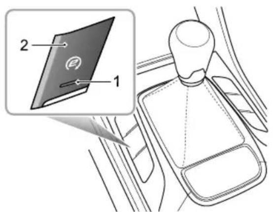
text_image
2 1I MainSwitchLamp
2MainSwitch
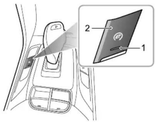
text_image
Diagram showing a car interior with a device labeled '1' and panel 2, highlighting a component with an icon.STARTING&DRIVING
EngineStop-Starthasbeenincorporatedintovehiclesinan efforttoreducefuelconsumption.Asthenamesuggests thesystemwillallowtheenginetobeswitchedoffwhen enginepowerisnotrequiredandthenautomaticallybe restartedwhenitis.
Thissystemdefaults"on"withtheSTART/STOPswitchin theONposition,theswitchindicationlightison(1inthe fig)andcanbeturnedoffbypassingthemainswitch(2in thefig).Thelampintheswitchwillextinguish.
Note: If vehicle is driving through deepwater, please use Stop-Start intelligent fuel savings system main switch (2 in the fig) to shutdown Stop-Start intelligent fuel savings system.
AutomaticShutdownofEngine

Although the engine is not running after an automatic stop, the system is still operating, therefore the following actions could be dangerous:
Leavingthevehiclewhiletheseatbeltisstill buckled,orthereisasubstituteseatbelt buckleinserted.
Vehicleswithautomatictransmission: The driverleavesthevehicle, withtheshiftlever stillinDriveposition(R/D/S).
Carryingoutworkorchecksintheengine compartment.
RefuellingthevehicleSTART/STOP switchmustbeswitched"OFF"orthkey removedfromtheswitch.
UndertheconditionwheretheStop-Startintelligentfuel savingsystemisenabled,theenginewillbeautomatically shutdownwherdetectingthefollowingactionscarriedbut bythedriveraswellasthevehiclestatusafterthevehicle
STARTING&DRIVING
isstopped, and the Stop-Startfuelsavingsystemindicator lampintheinstrumentpack 📷 illuminates:
- Gearboxmustbeinneutralandclutchpedalisreleased (manual).T transmissioninDrivewithfootbrakepressed (automatic).
- Vehicleisstationary, i.e. speed = 0 mph (0 km/h), and themaximum vehiclespeed before stopping exceeded 6 mph (10 km/h).
- Thereis nosignificantsteeringoperationafterthespeed drops below 6 mph (10 km/h).
- Thebonnetandthedriver'sdoorareclosedandseat beltissecured.
TheStop-Startintelligentfuelsavingsystemwillbedisabled andtheenginewillnotbestoppedautomaticallywhenthe followingsoccur:
•Coolanttemperatureisbelowapresetlimit. - Adaptivecruisecontrolsystemison.
- Frontdefrostison.
•TheA/Cdeterminesthatthetemperatureinsidethe vehicledoesnotmeetthetargetvalue. -
Lowbatteryorbatterytemperaturenotwithinthe desiredrange.
-
Thevacuuminthebrakingsystemfallsbelowapreset limit.
- Startermotortemperatureisaboveapresetlimit.
- Reversegearselectedorhasbeenselectedpriorto parking.
•Inhigh-altitudezones.
•Onthehill.
AutomaticEngineStart
Afterthecarisstopped,theenginewillbeautomatically startedwhendetectingoneofthefollowingdriveractions, theStart-Stopsystemindicatorlampontheinstrument pack 🔒 extinguishes:
• Vehicles with automatic transmission release the brake pedal with gearin Position; Depressthe brake/accelerator pedal with gearin P/N position; Shift the lever to R/D/S position.
Vehicle with anual transmiss Depreshe clutch/accelerator pedal with Neutralselected. Note When the EPB system or Auto Hold system is enabled, the engine will not automatically restart.
STARTING&DRIVING
Note: Insomeindividualsituations, themalfunction indicatorlampintheinstrumentwillilluminateinthe processofautomaticenginestart. Thisoccursdueto thelowvoltageduringstartup, notindicatingactual faults. Ifthemalfunctionindicatorlampremainson afterenginestart-up, seekalocalMGAuthorised Repairer.
With the engine stopped in the automatic Stop-Start condition, the following actions will cause an automatic restart:
- Frontdefrostselected.
- Adaptivecruisecontrolsystemison.
- Activationoftheairconditioner, and the temperature insidethevehicledoesnotmeetthetargetvalue.
- Batterypowerfallsbelowapresetlimit.
•Thevehiclebeginstomove. - Thevacuuminthebrakingsystemfallsbelowapreset limit.
•TheStart-Stopmainswitch(2)ispressed. Ifanyofthefollowingoccuraftertheengineisautomatically stopped,theenginecanonlybemanuallystarted,at
thistime,theStart-Stopsystemindicatorlamponthe instrumentpackextinguishes:
• Thedriversideseatbeltisunbuckled.
• Thedriver'sdoorisopened
•Thebonnetisopened
Note:Extremelylowbatterypowermayresultinthe enginenotre-startingautomatically,orevenusingthe key.Inthisinstance,externalpowerisneededtostart theengineorthebatterywillrequirere-charging.See thesection'EmergencyStarting'inthe'Emergency Information'Chapter.
Battery

Wheharging/dischargebattery, starting with external power sourceorsupplyingpowerfromthevehicle, thenegativecablemustbeconnectedto vehiclebodyearthpoint,ratherthanthe batterynegative.Failureretodothiswillresult inaccuratabattepowercalculation whichwilleffecttheautomaticenginestart.

DONOTdisconnectthebatterysensor unlessabsolutelynecessary. Removal willresultininaccuratebatterypower calculationwhichwilleffecttheautomatic enginestart.
Failuretooperatewithinthefollowingguidelineswilleffect batteryperformanceandautomaticStart-Stopcontrol:
I Afterpowerinterruptions(batterydisconnection)the automaticStart-Stopfunctionwillbesuspendeduntil thevehicleisleftinalockedstateforatleast4hours whilstthesystemrelearnsthestateofthebattery.
2Ifthevehicleisruncontinuallyformorethan100 hoursuninterrupted,thStart-Stopfunctionwibe suspendeduntilthevehicleisleftinalockedstatefor atleast4hourswhilstthesystemrelearnsthestateof thebattery.
the battery requires replacement AL WAY Use genuine and manufacturer specification. Failure adhered this an affected automatic Start-Stopsystem.
Stop-StartIntelligentFuelSavingsystem Failure
IntheeventofaStop-StartIntelligentFuelSavingSystem failurecontactanMGAuthorisedRepairerTheStop-Start IntelligenfucSavingsystemabeffectedbaults withiotherehic systemtheventfailure contactanAuthorisedMGRepairer.
Starbeoperatior;Battery CapacityLoss
the case of serious battery power loss automatic Stop-Start and keystart may not be possible in this case refeto the Emergency Information chapter, Emergency Starting section for further details.
NotDONOTconnectthejumpbatterynegative cablhebatternegativrileuln inaccuratebatterypowercalculationwhichwilleffect theautomaticenginestart.
STARTING&DRIVING
CruiseControlSystem \*
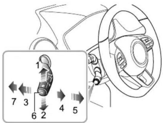
text_image
1 7 3 6 2 4 5-Acceleration(1)
-Resume(5)
- Deceleration(2)
-Set(6)
- Cancel(3)
•OFF(7)
•ON(4)
Cruisecontrolenablesthedrivertomaintainaconstant roadspeedwithoutusingtheacceleratorpedal. This isparticularlyusefulformotorwaycruising, or for any
journeywhereaconstantspeedcanbemaintainedforalengthyperiod.
CruiseControlSystemActivation
Cruisecontrolsystemisoperatedwithaleverlocatedat theleftsideofthesteeringwheelunderneaththelighting stalkswitch.
IWiththeSTART/STOPswitchintheON/RUNING position,ifthecruiseleverswitchisin'OFF'position (7),thenthecruisecontrolisinswitchedOFF.Ifthe cruiseleverswitchisin'ON'position(4),thenthe systemisinStandbymode.Switchthecruiselever to'ON'position(4),theyellowcruiseindicator theinstrumentpackwillllumateandthecruisecontrol systemisinStandbymode.

on
2Whenthecruise control system is in Standbymode, and currenspeed exceeds 25 mph (10 km/h), pressthe 'Set' button (6) at the end of cruise lever, they yellow indicator on the instrument will change to green, and the cruise control system enters into activation mode, the operatings speed range of cruise control system is 25 mph - 125 mph (40 km/h - 200
STARTING&DRIVING
km/h). Thetargetspeedofthecruisesystemwillbe setatthecurrentspeed,andthecruisesystemwill takeeffect.Atthistime,thecruisecontrolsystem willmaintainthesetspeedwithoutpressingthe acceleratorpedal.Withvehiclesfittedwithmanual transmissionitisrecommendedthatcruisecontrol shouldonlybeusedin3 ^rd gearandabove.
Note: Thesetspeedheldinthecruisecontrolmemory willbecanceledwheneitherthecruisecontrollever isswitchedto'OFF'position(7)ortheSTART/STOP switchturnedoff.
T argetCruiseSpeedAdjustment
Whenthecruise controlisactive, the 'targetspeed' can be increased or decreased:
Pushtheleverupwards(1)andhold,thenreleasethelever switchwhenthedesiredspeedisreached,thiswillincrease thespeed.
Pushtheleverdownwards(2)andhold,thenreleasethe leverswitchwhenthedesiredspeedisreached,thiswill decreasethespeed.
Pushtheleverswitchupwardsordownwardsbrieflyto increase/decreasethevehicletargetspeedinincrementsof 1mph(1km/h),thenthevehiclewillaccelerate/decelerate tothenewtargetspeed.
Pressingtheacceleratoratanytimewilloverridethecruise controlandallowaccelerationtoundertakemanoeuvres suchasovertaking. Releasingtheacceleratorwillreturn thevehicletothesettargetspeed.
Pause/StandBy
Whenthecruise control system is activated, the following operations will set the system to Stand by mode:
•Leverswitchmovedto'Cancel'position(3).
- Brakeorclutchpedalpressed.
The pooroadonditiobringstability control system(SCS)intooperationforsafetyreasons,the cruisecontrolsystemwillautomaticallyexittoStandby mode.
- Aninclinecausesexcessivedeclineinspeed, thecruise controlsystemshallautomaticallyexittoStandbymode.
•Electronicparkingbrake(EPB)isoperated.
STARTING&DRIVING
Resume
If the cruise control remains on after the disengagement, moving the levers switch to 'Resume' (5) will reinstate the targets speed to the setting prioritodisengagement.
Note:
- Neverusethecruise control system in thereverse gear.
- Donotusethecruise controlin unsuitable conditions, such as on slipper surfaces, excessively heavy rain or in traffic condition that donotsuit maintenance of constants speeds.
- Whennotinuse,ensuretheleverswitchisin'OFF' position(7).
- Whentheautomatictransmissionisin'Sport' mode, it is not recommended to set the cruise control system.
-
During the operation of cruise control system, the actual speed may deviate from the targets speed to some extent due to control precision or road conditions.
-
If the actualspeedis excessively lower than the targetspeedor SCS is activated dueto the hill or roadsurfaces, the cruise control system may automatically revert to Standbymode.
- Donotoperatetheswitchforexcessivelylong periods, or pressmultipleswitchessimultaneously, this may cause the system to fail. If this situation occurs by the START/STOP switch.
STARTING&DRIVING
AdaptiveCruiseControlSystem \*
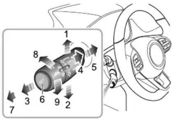
text_image
Diagram of a car's rotary dial indicator with numbered parts and directional arrows indicating rotation or movement.Speblimtcrease
/Accelerate(1)
SpeedimDecrease
/Decelerate(2)
Cancel(3)
On/Standby(4)
Resume(5)
Set6)
OFF(7)
Increase the Distance(8)
Reduce the Distance(9)

ThAdaptivCruisContrq(ACC)ystem designedomforstystemnabling thdrivetmaintainconstanspeedr distance from the airfront provides assistancetothedriver,ITDOESNO Treplace another drivers responsibilitiehen using the ACGtimportantathatheriver maintainconcentrationALLtimes.

DuringoperationoftheAdaptiveCruise Contryste(AC)autonomous braking vehicle limited therefore ESSENTIAthathedrivemaintains concentrationobservethdocalawsroad andtrafficconditionsnifantime feethenlangetthemselves surroundingtheyshouldpplyhbrakes and disconnecteACC.
The System automatically with between constanspeedruisenda followingruise control dependingonwhethericandetectvehicledirectlyahead. Constarspeedruiscontrapermittedetween
STARTING&DRIVING
20mph-90mph(30km/h-150km/h)orcarfollowingcruise controlbysettingthedistancebetweenthevehicleand thevehiclesdirectlyahead.
WhenactivatediftheACCsystemdetectsacarinthe samelanedirectlyaheaditmayaccelerateorgentlyapply thebrakesofthecartomaintainthesetfollowingdistance.
Note: The Adaptive Cruise Control System (ACC) is designed for motor way cruising or any other journey where a constants speed of distance between your car and the vehicle in front can be maintained for a lengthy period.
AdaptiveCruiseControlSystemActivation
The Adaptive Cruise Control system is operated with a leverswitch located, at the left side of the steering wheel underneath the indicator / lighting stalk switch.
IWiththevehicleSTART/STOPswitchintheON position,iftheadaptivecruiseleverswitchisinthe 'OFF'position(7),thentheadaptivecruisecontrol systemisswitchedOFF.
2Movtheadaptivecruiseleverswitchtothe'ON' position(4), theadaptivecruisesystemstatusindicator ontheinstrumentpack illuminatesyellow, and the adaptivecruisecontrolsystemisintheStandbymode.
3Thesystemwillautomaticallydetectthespeedand positionofthevehicleahead,ifyourvehiclespeedis above3mph(5km/h),afterpressingthe'Set'button (6)attheendoftheadaptivecruisestalklever,the indicatorontheinstrumentpack willturngreen, andtheadaptivecruisecontrolsystementersthe Activatedmode,ittargetspeedistheactualspeed atactivation;ifyourvehiclespeedislessthan20mph (30km/h),thenthetargetspeedofthesystemisset at20mph(30km/h).Ifthespeedofthevehicleahead isgreaterthanthecruisetargetspeedofyourvehicle, yourvehiclewillmaintainthetargetspeedtoconduct constantspeedcruise;ifthespeedofthevehicleahead islowerthanthecruisetargetspeedofyourvehicle, itwillenterthecar-followingcruise,animationofyour carandthecaraheadseparatedbyagridisdisplayed intheinstrumentpackmessagecentre,inthismode theactualspeedmaybelessthanthesetttarget
STARTING&DRIVING
speed.Whilstinthecarfollowingcruisemode,you canfollowthevehicleaheadtoastop,iftheamount oftimethatthevehicleisinastoppedconditionis lessthanapproximately3secondsyourvehiclemay automaticallypullawaytofollowthevehicleahead,if thestoppedtimeexceeds3secondsyourcarwillnot automaticallypullaway,youwillreceiveapromptin theinstrumentpackmessagecentrerequestingyou tore-activatetheadaptivecruisecontrolusingthe methoddisplayed.

Afterfollowingthevehicleaheadtoa stop,thedrivermustobserveanylocal trafficlawsandensurethatthereareno obstaclesorothertrafficparticipants, suchaspedestrians,directlyinfrontof thevehiclebeforeallowingittopullaway andbegintofollowthevehicleahead again.

Whilstusingthecarfollowingcruise functionitisstronglyrecommendedthat thedriverdoesnottouchtheaccelerator pedal.Anyactivationoftheaccelerator willnotallowthesystemtoautomatically applythebrakesshouldthisbenecessary.

DONOTexitthevehiclewhentheACC carfollowingcruisefunctionhasstopped, oriskeepingthecarstationarBefore exitingthecartheshiftcontroller shouldbeintheParkposition,theparking brakeappliedandthepowerswitchin theOFFposition.

If the ACC system has already stopped the vehicle, and the ACC function is disabled, turned off or cancelled, the vehicle will no longer stay still, it may move forward or slip backward. When the vehicle is stopped and kept still by the ACC system, besuretobeready to apply the brakes manually.
STARTING&DRIVING
4Ifthevehiclespeedexceedsthemaximumfunction speedoftheACC90mph(150km/h)thesystemwill automaticallyswitchtotheStandbymode, thismeans thatallaccelerationandbrakingmanoeuvresmustbe carriedoutbythedriveraccordingtolocaltrafficlaws andtrafficandroadconditions.
5Iftheadaptivecruisecontrolsystemisalreadyinuse, thedrivers should pays special attention in the following conditions, select the appropriatespeed, and beready to take action or apply brakes.
IMPORTANT
When an image of your car and re are nd of the vehicle ahead separated by a grid, is displayed in the instrument pack message cent the ACC system will make any necessary responset to the vehicle ahead, if the image is not displayed the ACC system will NOT make any response, ther responsibility for any manoeuvres rest with the driver.
- Encountersavehicleorobjectwhichisstationary ortraversingthelanes.
- Approaching the vehicle ahead to fast, the adaptive cruise control system cannot apply sufficient braking force.
- Avehiclesuddenlycutsintothelaneinfront.
•Thevehicleaheadmakesanemergencybraking manoeuvre. - Anoncomingvehiclecrossesthecentreoftheroad andisdrivingtowardsyouinthesamelane.
- Encountersavehicledrivingatalowspeed.
- Encountersavehiclewithloadeditemsprotruding fromthebodyside,rearorroofofthevehicle.
- Encountersavehiclewithahigherchassis(e.g.,a truck).
- Encounterspedestrians on-motorvehicles or animals.
• The vehicle is driving on a steepslope, an uneven road or a complex traffic road section.
•Thevehiclemakesasharpturn. - Waterorsnowsplashedbysurroundingvehicles hinderscameraorradardetection.
STARTING&DRIVING
- Excessiveweightbeingcarriedinthebootspace orcargoareacausingthefrontofthecartopoint upwards.
•Afaultexistsinthesystem.
Note: Manual deactivation of either the Traction Control System (TCS) or Stability Control System (SCS) will inhibit the operation of the Adaptive Cruise Control (ACC).
AdaptiveCruiseT argetSpeedAdjustment
Inordertosetthetargetspeed, theadaptivecruisecontrol system must be in an active mode.
Usetheacceleratorpedaltoreachthedesiredspeed,short pressthe'Set'button(6)ontheendoftheadaptivecruise switchlever,releasethecontrolbuttonandaccelerator pedal.Thevehiclewillcruiseatthedesiredspeed.
Movetheleverswitchupward(1)andhold,thetarget speedwillincreaseuntilthedesiredsetspeedappearsin theinstrumentpack,thenreleasetheswitch.Whenitis confirmedthatthereisnovehicleinfrontofyourvehicle
orthevehicleaheadexceedsthepreselectedfollowing distance,thespeedwillbeincreasedtothesetspeed.
Movetheleverswitchdownward(2)andhold,thetarget speedwilldecreaseuntilthedesiredsetspeedappearsin theinstrumentpack,thenreleasetheswitch.Whenitis determinedthatthevehicleaheaddrivingslowlyiswithin thepre-selectedfollowingdistance,thevehiclespeedwill decreaseandkeeptheselectedfollowingdistance.
Note: Brieflyoperattheadaptivecruiseleverswitch upward(1)ordownward(2)once, the targetspeedwill change5mph(5km/h), pressandholdtheleverupward ordownwardandthespeedwillincreaseordecrease in1mph(1km/h)increments, releasetheleverwhenthe desiredspeedreadingisdisplayed.
Note: If the vehicle ahead continually makes hard acceleration or deceleration manoeuvrestheadaptive cruise control may not be able accurately maintain the required distance between vehicles. It is important that the driver always concentrates and pay attention to the current vehicle position and situation in case they need to make abraking or avoid ance-manoeuvre.
STARTING&DRIVING
AdaptiveCruise TargetFollowingDistance Adjustment
When the adaptive cruise control system is activated, rotatetheswitch on the end of the lever upward (8) or downward (9) to adjust the following distance, you are able to toggle between 3 distances settings, the current following distances setting will be stored by the system until it is changed, and displayed in the message centre in the instrument pack.
Alwaysselectanappropriatefollowingdistancethatis relativetothecurrentspeedofyourvehicleandthe vehicleyouarefollowing,thegreaterthespeed,the furtherthedistance.ALWAYSconsidercurrenttraffic, roadandweatherconditionswhenmakingyourselection.
AdaptiveCruisePause
Whentheadaptivecruisecontrolsystemisactivated,move theleverswitchtothe'Cancel'position(3),andthesystem willexittotheStandbymode.
AutomaticDeactivationofAdaptiveCruise
In the followingsituations, the ACC maybe automatically deactivated, this transfers full control of the vehicle to the driver.
- Movetheleverswitchto'Off'position(7).
- Pressthebrakepedalwhilstthevehicleisinmotion.
- MovetheshiftleverawayfromtheDposition.
• Thedriverunfastenshis/herseatbelt.
- Pressandholdtheacceleratorpedalbeyondapreset timeperiod.
- Openanydoor, bonnetortailgate.
• PulltheEPBswitchuptoapplytheparkingbrake.
- Followthevehicleaheadtoastopandthestoptime exceeds3mins.
- Thesensororradarviewisblocked, the ambient light conditiontriggersthepresetsafeexitmechanismofthe lightsensor, orthesystemfails.
Note: Iffollowingthevehicleaheadtoastopwith theadaptivecruisecontrolsystemenabled, if any of the following conditions occur whilst the vehicle is in a stopped state, the EPB will automatically be applied:
• Thedriverunfastenshis/herseatbelt.
• Thedriverdoorisopened.
• Thestoptime exceeds 3 mins.
AdaptiveCruiseOverride
If the driver has a cause to set the accelerator pedal when the ACC is activated, the vehicle will remain in Cruise mode while the vehicles speed increases. When the accelerator pedal is released, the ACC will resumeto operate at previously set cruisespeed.
If the driver accelerates to a higherspeed and then releases the accelerator the ACC will decrease the target cruise speed in more gradual manner. If it is necessary to decrease the target cruises speed rapidly, the driver may manually move the levers switch 'Deceleration' (2).
Note: If the accelerator pedal is pressed and held abovethe preset time period the ACC may exit to the Standbymode.
AdaptiveCruiseResume
If the ACC system has reverted to, or beenswitched to, the Standbymodeit can be reactivated by moving the lever switch to 'Resume' position (5). Thetargetcruisespeed will automatically besettothetargetspeed before exiting the adaptive cruise control system.
Whendrivingazhighspeed,ifthedriverresumesto alowertargetcruisespeed,theACCwilldecreaseto thetargetcruisspeethnograduahanner. necessarydecreasteattargetcruisspeed rapidlythedrivermaymanuallymovetheleverswitch 'Deceleration'(2).
CleartheSpeedMemory
theveswitchmovedOFFPositio(7)or theehicl&TART/STORwitchswitchedohOFF position,thesystemmaycleartheadaptivecruisecontrol setspeedinthememory.
STARTING&DRIVING
SpecialDrivingEnvironments
TheAdaptiveCruiseControl(ACC)systemhasit's limitations.Listedbelowaresomeconditionsthatmay bebeyondthesafeoperatinglimits.Thedrivershould maintaincontrolofthevehicleandmustremainalertat alltimes.Theyshouldpayspecialattentiontothetraffic conditionsandsurroundings,selecttheappropriatespeed andbereadytotakeanyrequiredactions.
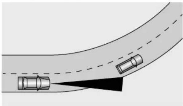
natural_image
Diagram of a curved road with two cars, one highlighted by a black arrow (no text or symbols)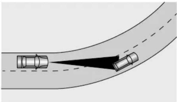
natural_image
Diagram showing two cars driving on a curved road with a dashed lane and a black arrow indicating direction (no text or symbols)Whenturningatanintersectionorfollowingvehicleinto, oroutofacurve,theACCsystemmaybeunabletodetect thevehicleahead,evenifitisinthesamelane,itispossible thesystemmaydetectavehicleinanotherlane.
Note: Donotusetheadaptivecruisecontrolsystem onentrance/exitrampsorsharpbends.
STARTING&DRIVING
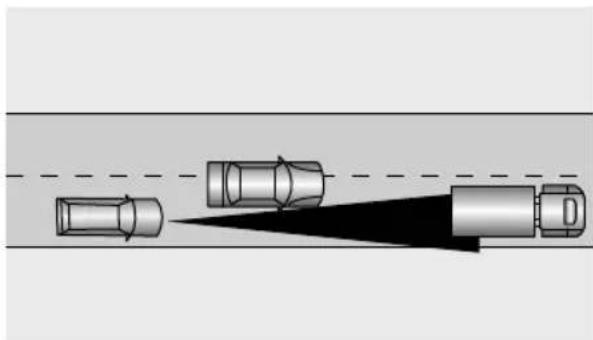
natural_image
Diagram showing a vehicle approaching a road with a shadow, no text or symbols presentIfthevehicleaheadchangeslanes, butdoesnotdriveinto thelanecompletely, theACCsystemmaybeunableto detectthevehicle.
Ifthevehicleaheadchangeslanes,butdoesnotexitthe lanecompletely,theadaptivecruisecontrolsystemmay determinethatthevehicleaheadhasexitedthelaneand acceleratetoanypresetspeed.
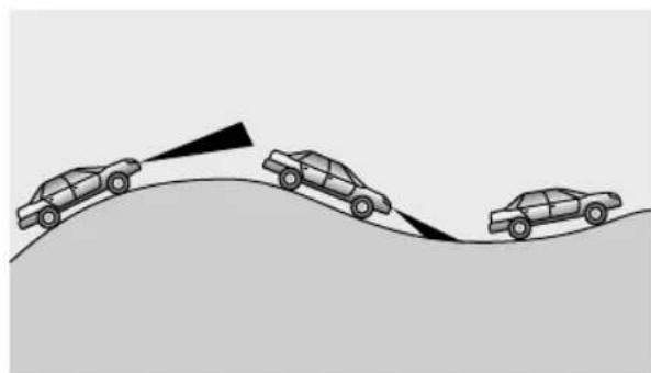
natural_image
Diagram showing three cars on a curved road with a triangular trajectory and a pointed arrow, no text or symbols present.Whendrivingonunevenroadsthatmayincludesteep climbsordipspleaseDONOTusetheACCsystem.
STARTING&DRIVING
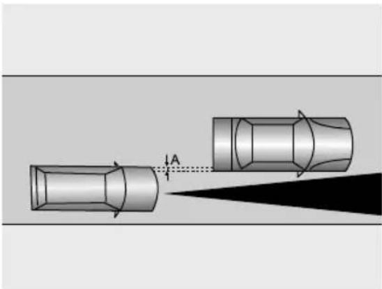
natural_image
Diagram showing two cars with directional arrows and a spotlight, no text or symbols presentWhendrivingbehindavehiclethatisonlypartially overlappingyourvehicle,'A'inthegraphic,theACC systemmaybeunabletodetectanything.
Note: Please DONOT usetheadaptive cruise control system in the following situations:
•Theambientlightlevelisinsufficientlylow, extremelybright,ortheforwardlightingofthe vehicleispoororcompromised.
•Thefrontviewcamerainthewindscreenand/or radarsensorinthefrontbumperhavearestricted fieldofvision,orsevereweathersuchasheavyfog, heavyrain, heavysnow, ice, etcareaffecting the sensor'sfieldofview.
•Inconditionswherethedemistfunctionofthe windscreenisimpaired.
- Whendrivingthevehicleonalow-frictionroad (rapidchangesytractionmayresultin excessivewheelslip).
- Whendrivingonastrongreflectiveroadsurfaceas aresultofrain, snow, orice.
When the adam may be affected by electromagnetic interference (forexample, metal objects such as rails and metal plates for road construction).
Afterposition and change(for example,collision,vibration).
Radarsignalsouldbeincorrectlyreflectedbylocal conditions(e.g.,inmulti-storeycarparks,tunnels, waterjetsfromsprinklers,etc.)thesemaydegrade thefunctionoftheradarsensor.
ParkingAidSystem \*
UltrasonicSensorParkingAid

The purpose of the parking aid to assist the driver in reversing! Thesensors may not be able to detect obstacles of certainty, e.g. narrow posts or small objects nom more than afewinches wide, small objects closeto the ground, objects abovethetail gate and some object with non-reflectives surfaces.

Keepthesensorsfreefromdirt,iceandsnow. Ifdepositsbuilduponthesurfaceofthe sensors,theirperformancemaybeimpaired. Whenwashingthecar,avoidaiminghigh pressurewaterjetsdirectlyatthesensors fromcloserange.
RearParkingAid
The ultrasonicsensors in therear bumper monitor the area behind the vehicle to search for obstacles. If any obstacle is detected, the system will calculate its distance from the
rearofthevehicleandcommunicatesthemessagetothe driverbysoundingwarningchimes.
ParkingAidinOperation
When the START/STOP switch is in the ON/RUNNING position, there are parking aid is enabled automatically when reverse gear is selected, it is switched off as soon as reverse gear is disengaged. A short beep is given by the parking aid within 1 second after selecting reverse gear to indicate that the system is operating normally.
Note: Ifalonger, higherpitchedsoundisemitted for 3secondswhenreversegearisselectedthisindicates afaultinthesystem. In this case seek assistance from your MGA authorised Repairer.
With the parking aid enabled, when obstacles are detected, the system will give sounds indifferent frequencies (there might be blind areas).
STARTING&DRIVING
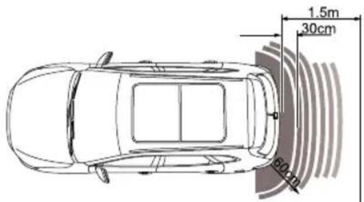
text_image
1.5m 30cm 60cm•Ifanobstacleislocatedwithin1.5mrangeofthe rearparkingaidsensororwithin0.6mrangeofthe cornersensor,thewarningcommences.Asthecar movesclosertotheobstacle,theaudiblesoundsare transmittedmorerapidly.
• Oncetheobstacleiswithin30cmrangeoftherear bumper, theaudiblesoundswillmergeintoacontinuous warning.
ParkingCamera \*

The purpose of the parking camerasystem isto assist the driver during reversing! The camera has limited field of view and cannot detect obstructions outside the field of view.
Somemodelshavearearparkingcamerafittedbetween therearlicenseplatelamps.Whenreversegearis selected,thecamerawidisplayanimagofwhatis immediatelybehindthecarThisimagewillbeshownon theinfotainmentsystemdisplay.
STARTING&DRIVING
RearDriverAssistanceSystem
SystemOverview

Thereardriverassistancesensorsmay misidentifiesomesurroundings,suchas roadsidebuildingsorguardrailsandprovide afalsealarm.

Theeffectiverecognitioncapabilitiesofthe rearsensorscanbelimitedbyobjectssuch asroadsidebuildings, guardrails, changesin pitchangleofthecarduetoheavyloading, roadconditionssuchasbendsorbumpsor weatherconditionssuchassnowandiceetc. Anyoftheabovemaytriggerafalsealarm.

Thereardriverassistancefunctionisonlyan aide,itisNOTasubstitutefortheattention ofthedriver. Thedrivermustalwaysremain incontrol,observethesurroundingsanddrive safely.

Thereardriverassistsystemmaynotprovide adequate warning of very fast approaching vehicles or operate correctly on tight curves of radius.

Thereardriverassistsystemwillnotoperate correctlywhilsttowingatrailerorcaravan.

The correct operation of therearsensors will be compromised if they are misaligned due to accident damage. This may cause the system to automatically shutdown.

Toensure that the adarsensors work correctly, the bump should be kept free of snow and ice and must not be covered.

Useofnonrecommendedmaterialsor painoneabumperepairmaljava detrimentaleffecontheoperationofthe rearsensors.Pleaseonlyuserecommended materials.
STARTING&DRIVING
Thereardriverassistancesystemincludesblindspot detection(BSD),lanechangeassist(LCA),rearcross trafficalert(RCTA)anddooropenwarning(DOW) functions.
Thereardriverassistancemodulesaremountedatthe rearofthevehicleoneachside,theycanassistindetecting vehiclesbehindortothesideofyourvehicle.
Thewarninglampstosupportthissystemarelocated withintheLHandRHdoorquarterlighttrims,theywill illuminateorflashtowarnofanapproachingobjectorcar toassistyouinmanoeuvringthecarsafely.
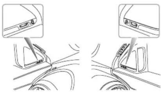
natural_image
Diagram showing two car interior components with arrows indicating movement or assembly (no text or symbols)Note: Theradarrequirescalibrationonnewvehicles orforvehiclesofwhereareardetectingradar sensorhasbeenreplaced. Thereardetectionradar sensorspossessanautomaticcalibrationfunctionto compensateforinstallationerrorwithinacertain rangeWhenthevehicleisrunning,theradarwill automaticallyenterthecalibrationstate.Duringthe calibrationprocess,thesystemwillprovidelimited functions,andthealarmmaybeinaccurate.Upon completionofthecalibration,thesystemwillresume allfunctions.
SwitchingtheSystemFunctionsOn/Off
Thereardriverassistsystemfunctionswitchescanbe accessedviatheinfotainmentscreen.
Select:'VehicleSettings','DrivingAssist'and'RearDriving Assist'(youmayhavetoscrolleftorrighttoaccessthis option).SelectON/OFFtoactivate/deactivatethesystem. A warningmessagetoalertyouofyourchoicewillbe displayedinthemessagecentreintheinstrumentpack.
Ifthe'RearDrivingAssist'isON,thesubsystemmenu willbecome'live'andyoucanselecttheON/OFFoption
foreachofthesubsystems.Ifthe'RearDrivingAssist'is switchedOFF, noneofthesubsystemswillbeselectable andtheentiresystemwillbeinanOFFstate.
Whenthevehicleisrestarted,thesystemwillkeepthe previouslystoredswitchsettings.
SystemFunctions
BlindSpotDetection(BSD)
Whenthevehicleisdrivingforward,thesystemwill monitorformotorvehicleslocatedintheblindzonesof theleftandrightexteriormirrors.Whentheconditions foractivatingtheblindspotdetectionfunctionaremet,the correspondingwarninglampswillilluminate.Subsequent operationoftherelevantindicatorwillcausethewarning lamptoflashtoremindthedriverofanapproaching vehicle.
STARTING&DRIVING
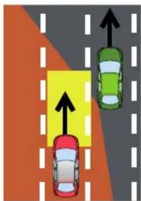
text_image
Diagram showing three cars on a road with directional arrows indicating movement or traffic flowThe conditions for activating the blind spot detection function include:
IReardriverassistancesystemisintheONstateand nofaultsarepresentinthesystem.
2Blindspotdetection(BSD)functionisenabled.
3Thevehiclespeedisabove20mph(30km/h).
4Therearemotorvehiclesintheblindzoneofthe vehicle. Thesystemmonitorsboththeleftandright
ofthevehicle, themonitoredareasare2mahead, 7m behindtherearofthevehicle, and 4.7m from theside of the vehicle.
Note: The warning lampswill not to illuminate whilst you are overtaking another vehicle and your speed is greater than that of the vehicle you are passing, even though it is in the blind zone.
STARTING&DRIVING
LaneChangeAssist(LCA)
Whenthevehicleisdrivingforward,thesystemwill monitorformotorvehiclesapproachingrapidlyinthe adjacentlanes.Whentheindicatorsareactivated,andthe conditionsforactivatingthelanechangeassistfunction aremet,thesystemwillflashtherespectivewarninglamp towarnthedriverofanapproachingvehicle.Thisaimsto helpavoidcollisionswhenchanginglanes.
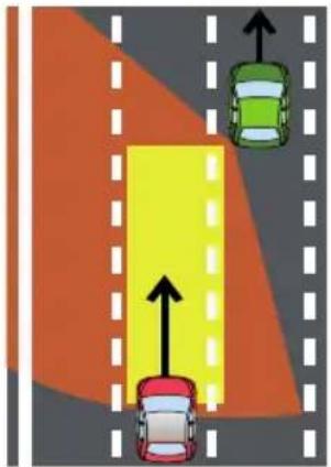
natural_image
Diagram showing car traffic flow with a yellow lane and directional arrows, no text or symbols presentThe conditions for activating the lane change assist function include:
IReardriverassistancesystemisintheONstateand nofaultsarepresentinthesystem.
2Lanechangeassist(LCA)functionisenabled.
3Thevehiclespeedisabove20mph(30km/h).
4 Thespeedoftheapproachingvehicleishigherthanthe speedofyourvehicle.
5Theapproachingvehicleentersthedetectionareaof theLCA,themonitoredareasare7m-70mbehind yourvehicleand4.7mtothesideofyourvehicle.
6Theapproachingvehicleislikelytohaveacollisionwith yourvehiclewithin3.5seconds.
STARTING&DRIVING
RearCrossT rafficAlert(RCTA)
Whenthevehicleisreversing,thesystemwillmonitor vehiclesapproachingfromtheleftandrightrear.When theconditionsforactivatingRCTAfunctionaremet, thewarninglampsonthecorrespondingsidewill illuminate,simultaneouslyawarningtriangleiconforthe correspondingsidewillbedisplayedintheinfotainment screentoalertthedrivertothesituation.
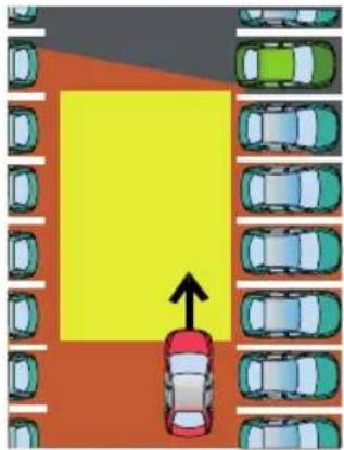
natural_image
Top-down view of a parking lot with multiple lanes and a central yellow area marked by an upward arrow (no text or symbols)The conditions for activating there are cross-traffic alert function include:
IReardriverassistancesystemisintheONstateand nofaultsarepresentinthesystem.
2Rearcrosstrafficalert(RCTA)functionisenabled.
3ThevehicleisinReversegear.
4Thevehiclespeedislessthan5mph(9km/h).
5Thespeedofthevehiclebeingmonitoredisabove 5mph(9km/h).
6Themotorvehicledrivesacrossthesystemdetection areas. Theareasmonitoredtotheleftandrightofthe vehicleare5mbehindtherearofthevehicle,and25m fromtheside.
7Theapproachingvehicleislikelytohaveacollisionwith yourvehiclewithin2.5seconds.
STARTING&DRIVING
DoorOpenWarning(DOW)
Whilstthevehicleisstationary,theDoorOpenWarning systemmonitorsthesurroundingareaforapproaching vehicles,motorcyclesandbicycles.
If the approaching object meets the conditions programmed into the system that corresponding warning light will illuminate to warn the occupant of the approaching object and assist in avoiding any collisions when the door is opened.
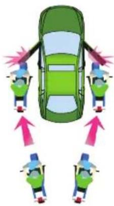
natural_image
Top-down diagram of a car with four seated figures and directional arrows indicating movement or force (no text or symbols)STARTING&DRIVING
The conditions for activating the door open warning function include:
IReardriverassistancesystemisintheONstateand nofaultsarepresentinthesystem.
2Dooropenwarning(DOW)functionisenabled.
3ThevehicleisinACCorignitionON/RUNNING state.
4Thevehicleisinstationary.
5Thespeedofthevehiclebeingmonitoredisabove 5mph(9km/h).
6Thevehicledrivesacrossthesystemdetectionareas. Thedetectionareasare:Rearwardofthedoor mirrorsand2.4metresfromeachsideofthevehicle.
7Theapproachingvehicleislikelytohaveacollisionwith yourvehiclewithin2.5seconds.
Note: Thedetectionarea, collisiontimethreshold value and vehiclespeed provided in the system function description are just for your reference.
DrivingAssistSystem
The driving assists system includes Speed Assist System (SAS), Lane Departure Warning System (LDW), Lane Departure Prevention System (LDP), Lane Keeping Assist System (LKA), MGPilot System, Forward Collision Warning System (FCW), Automatic Emergency Braking System (AEB) and Automatic Emergency Braking System for Pedestrians (AEBP). Under certain conditions, the driving assists system can detect three road environments information ahead of the vehicle by utilising a frontview camera and front detection radar. This information is used to overlay warning messages or provide assistance to help the driver control the vehicle remains safely and reliably. The frontview cameras are located at the upper middle of the windscreen (in the interior rear view mirror base cover), the front detection radar is located at the lower middle of the front bumper.
DescriptionofFrontViewCamera
Calibrationoffrontviewcamera
Thefrontviewcamerawillrequirere-calibrationafterany ofthefollowingoperations:
Removalandrefittingofthefrontviewcamera.
Replacementofthewindscreen.
Note: The calibration offrontview camerarequires professional knowledge and tool calibration is required, please seek an MGA authorised Repairer.
Not after completing the calibration possible to immediately select any driving assist options. The vehicle powersystem must be switched to the OFF position and then switched to ON/READY.
Obstructionofthefrontviewcamera
Onoccasionthefrontviewcameraviewmaybecome obstructedbyforeignobjectsorstainsontheglass. Inthesecasesapromptmessagewillappearinthe informationcentre.Pleasecleanorwipeimmediately.
STARTING&DRIVING
In the following situations, the detection performance off frontview camerawill be affected:
- Drivinginpoorweatherconditionswherevisibilityis reducedduetothickfog,heavyrainorsnowetc.
- Thefrontviewcameraisaffectedbylight,forexample lowlightlevelsatnight,poorauxiliarylighting,excessive backlightingintheview,lightfromoncomingvehicles, abruptchangeofbrightnesssuchasquickbright/dark jump(tunnelentrance/exit),drivingonsurfaceswith strongreflectiveproperties(roadsurfacecoveredwith waterorsnow),ordrivinginplaceswithinsufficient light,suchunnelsurrounddebylbuildings, undergroundparkinglots,etc.
- Thefrontviewcameraispartiallyorfullyblockedby obstacles,e.g.dust,foreignobjectsonthewindscreen.
• Thewindscreeninviewisdamaged. - Notcalibratedafterremoving/refittingthefrontview camera.
- Notcalibratedafterremoving/refittingthewindscreen.
• Thefrontviewcameraisnotsecuredinplace.
The surface windscreen clean (including wipersweep).
• Thewindscreenisnotcleanedregularly.
- Thedemist/defrostactiononthewindscreeninefficient inwetconditions.
DescriptionofFrontDetectionRadar
Calibrationoffrontdetectionradar
Frontdetectionradarre-calibrationisrequiredafteranyof thefollowing:
- Frontdetectionradarmis-alignmentfailure,forexample thepositionofthefrontdetectionradarhaschanged.
- Remove/refitthefrontdetectionradarorradarbracket.
- Remove/refitthefrontanti-collisionbeam.
- The four-wheel alignment parameters or the driving axis have changed.
Note: If the front detection radar is subject to strong vibration or light impact, themounting position of the front detection radar need to be checked and re-calibrated as necessary.
Note: The calibration off front detection radar requires professional knowledge and tools. If calibration is required, please seek an MGA authorised Repairer.
Frontradarperformancewillbeefectedinthe followingsituations:
- Whenthefrontdetectionradariscoveredbymud, snow,excessivewater(rain)orwatersprayfromthe road.
- Whentheradarorsurroundingareasarecoveredby objectssuchasself-adhesivelabelsorauxiliarylamps.
- Sometargetsmayaffectandweakenthedetection capabilityofthefrontdetectionradar,suchasroad barriers,fencesandtunnelentrances.
- Whenthefrontdetectionradarissubjecttostrong vibrationorslightimpact.
- Whenthefrontdetectionradarisaffectedbythe environment, strong electromagnet field interferenceorduetothetargetitself.
Note: Anysnowthatgathersonthefrontradarmay beremovedusingasoftbrush, andanyiceshouldbe removedusingaproprietydeicingspray.
Notopidpolliscontactithe frontradarmodule, this mayausmisalignment. Andamagowevelightnayausystem performanceissues.
STARTING&DRIVING
SpeedAssistSystem(SAS)

Theintelligentspeedlimitisanauxiliary function, it may display an incorrect speed limit value on the speed limit value in the instrument pack duetovarious factors. As a result, the vehicles speed is not restricted within the correct range. The driver still need to observ the speed limit of three road traffic, and speeding is strictly prohibited.

Thefrontviewcameracannotrecognise speedlimitsignspaintedontheroadsurface. ThedriverMUSTobservethesespeedlimits andadjustthetheirspeedaccordingly.
Thespeedassistsystemsettingsareavailableviathe infotainmentsystem.Whentheadaptivecruisecontrol systemisOFF, the following three functions can be selected:

ISpeedLimitInformationFunction(SLIF):Thevehicle detectsaspeedlimitsign(asshownabove)atthe roadsidewiththefrontviewcamera. Thespeedlimit signidentifiedwilbedisplayedortheinstrumentpack. Whenthevehiclespeedexceedsthespeedlimitbya presetamount,avisualwarningintheinstrumentpack willalertthedrivertocontrolthespeedmanually.
2ManualSpeedAssist(MSA): Thedriversetsthe maximumspeedusingtheadaptivecruisecontrol lever. Thesystemwillactivelyinterveneandkeepthe vehiclespeedwithinthepermittedmaximumspeed limiAndanacousticwarningandavisualwarning willbeavailableduringtheintervention.Pleaserefer tothesection"Speedsettingsofmanualspeedassist".
3IntelligentSpeedAssist(ISA):Thevehicledetectsa speedmist(showabove)theoadside with frontviewamerThespeedmistign identifiedwillbedisplayedontheinstrumentpack. Thesystemwillautomaticallyinterveneandmaintain speedcontroltokeepthevehiclespeedwithinthe permittedmaximumspeedinAnacoustic
warningandavisualwarningwillbeavailableduring theintervention.
Note: It is recommended to switch the speed limit information function and intelligent speed assist function when the km/h speed units are selected. In such situations, the system will only recognize the number displayed in all speed limits signs and uses this data for km/h, even if the speed limits sign refer to mph. When km/h is selected, the system will also recognize the nationals speed limits sign as speed limit sign of 60 km/h.
Speedassistancesystemsetting
Theoperatinginterfaceforthespeedassistancesystem islocatedintheinfotainmentdisplay.Enterthevehicle settinginterfacetolocatethedrivingassistoption,scroll acrosssthepagetofindthesettinginterfaceforthespeed assistancesystem:
I Thespeedlimitinformationfunctiondefaultsto enableteST ART/ST Switchbo ON/RUNNING.PresstheUP/DOWN/LEFT/RIGHT buttonintheRHsteeringwheelmultifunctionswitch
packtoselectthecurrentspeedoptioninthetrip computer.Underthisinterface,longpressingthe OKbuttontoturnon/offthespeedlimitinformation function.
2T ouchthecorrespondingbuttonontheinfotainment displaytoselectthespeedassistmode:manualspeed assistandintelligentspeedassist.
Speedsettingsofmanualspeedassist:
After the manual speed assist function is enabled the speed limit value can be set by using the adaptive cruise control leveras follows:
IWiththemanualspeedassistfunctionenabled,the initialspeedlimitvalueisdisplayedas“—”onthe instrumentpadMovetheadaptivecruisecontrol leverupanddown(1and2inthefigurebelow)to adjustthetargetspeedlimitvalue.Movingthelever upordownoncewillincreaseordecreasethetarget speedby5mph(5km/h)Holdinghdeverupordown, thespeedlimitvaluewillcontinuouslychangeinunits of5mph(5km/l):esstheSETbutton(3inthefigurebelow),themanualspeedassistfunctionwillbe
STARTING&DRIVING
activated. When the current actualspeed is slower than 20mph(30km/h), the speed limit value displayed on the instrument pack is defined as 20mph(30km/h). If the current actualspeed ( ≥ 20mph(30km/h)) is higher than the set speed limit value, the speed limit value displayed on the instrument pack will be defined by the current actualspeed.
2Afterthemanualspeedassistfunctionisactivated, thedrivercanstillsetthevehiclespeedbymoving theadaptivecruisecontrolleverupanddown.Ifthe currentactualspeedexceedsthespeedlimitvalueset bythedriver,thesystemwillimmediatelyreducethe speeduntilitisbelowthesetspeed.
3Afterthemanualspeedassistfunctionisactivated,the drivercanpresstheSETbutton(3inthefigurebelow) ontheadaptivecruisecontrollevertoreinstatethe systemtostandbystate.PresstheSETbuttonagain, themanualspeedassistfunctionwillberesumed.The instrumentpackwilldisplaythesetspeedlimitvalue.
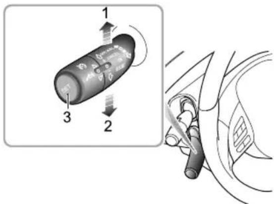
text_image
Diagram showing a car interior with labeled parts and directional arrows indicating motion or movement.
Whenthespeedlimitinformationfunctionor intelligentspeedassistfunctionisenabled,thespeedlimit valueindicationilluminates.The"NNN"isdisplayedas"—Whenthevehiclepassesthefirstspeedlimitsign identified,thespeedlimitindicationdisplaysthereal-time speedlimitvalue.
Note: Whenthevehicleneedstochangelane, makea turnorturnaroundatanintersectionandthedriver usesanindicatorinadvanceandslowsdown, the originalspeedlimitvalueontheinstrumentpackwill beresetanddisplayedas“—”untilanewspeedlimit signisdetected. If the conditions are not met, the originalspeedlimitvalue will be maintained and not bereset. ThedriverMUSTobservethespeedlimits and adjust the theirspeed accordingly.

Whenthenationalspeedlimitsignisidentified andthespeedlimitinformationfunctionorintelligent speedassistfunctionisenabled,thenationalspeedlimit indicationilluminates. Thesetwofunctionswillworkusing 60mphasthenationalspeedlimit.

Whentheintelligentspeedassistfunctionis enabled, thesystemindicatorlampontheinstrumentpack illuminatesgreentheintelligentspeedassistfunction detectsafaultorfailure, theindicatorlampwillflashyellow thenextinguisPleasetrytorestartthisfunctidh.
thisfunctioncannotbeturnedon,pleasecontactanMG AuthorisedRepairer.

Whenthespeedlimitinformationfunctionor intelligentspeedassistfunctionisenabled,andthefront viewcameradetectsaspeedlimitsignwithtextmessage below,thewarninglampilluminatesyellowtoremind thedrivertorecognisethetextmessagebythemselves. Thecameracannotrecognisethetextmessagesprovided belowthespeedlimitsign,suchasauxiliarylane,100m ahead,schoolsection,7:00-10:00ecamerawill recognisethespeedlimitsignwithtextmessagesasa normalspeedlimitsign. Thedriverisrequiredtomake correctjudgementaccordingtothetextmessage.

Whenthemanualspeedassistfunctionis enabled, thesystemindicatorlampontheinstrument packilluminatesyellow Whenthefunctionisactivated bypassingtheSETbuttonontheadaptivecruisecontrol lever , thesystemindicatorlampilluminatesgreen. If the actualspeedexceedsthemaximumvaluethatcanbe set, thesystemwillremaininthestandbystate, and the
STARTING&DRIVING
indicatorlampremainsyellow.Ifthemanualspeedassist functiondetectsafaultorfailure,theindicatorlampwill flashyellowthenextinguish.Pleasetrytorestartthis function.Ifthisfunctioncannotbeturnedon,please contactanMGAuthorisedRepairer.
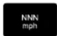
Whenthemanualspeedassistfunctionis enabled,thespeedlimitvalueindicationilluminates.The "NNN"isdisplayedas"—.Movtheadaptivecruise controlleverupanddowntoadjustthetargetspeedlimit value.The"NNN"willnowshowtheadjustedspeedlimit value.
The drivercandirectlyswitchoff, ortemporarilysuspend the speedassistsystembycarryoutthefollowingactions:
Tlotemporarilyexceedthespeedlimit(overtaking manoeuvre),presstheacceleratorpedalharthe indicatorlampthinstrumentpackilluminates green,andthespeedlimitvalueflashes.
QentlypressthSETbuttonontheendofthe adaptivecruisecontrollever,theindicatorlampinthe
instrumentpackwillchangetoyellow.PresstheSET buttonagaintoresumethefunctions.
Novtheadaptivecruisecontrolleverto"ON" positiontoswitchthespeedassistancesystemoff. Thentheindicatorlampintheinstrumentpackwill extinguish.
The speed limit format function and
intelligentspeedlimitfunctionmaybeimpaired
inthefollowingsituations:
Thedetectionperformanceoffrontviewcamerais affected.
The vehicle is driven at a high speed.
The speed limits signs are blocked by trees along the road, ice/frost, snow, dust, etc.
The impedimentigraincorrectplaced damaged.
Therearemultiplespeedlimitsignsabovethelaneor onthesidesoftheroa Currently, thefrontview
cameracanonlyrecognisethespeedlimitsignsforthe laneinwhichthevehicleisbeingdriven.
6 Nonstandardspeedlimitsignsorsignsthatcontain additionalinformation.
7Thespeedlimitsignssetupataforkintheroad,ona bendoron-ramp/off-ramp.
8Duringmanoeuvressuchaslane-changing.
IMPORTANT
- The cameramaynotcorrectlyrecognisespeedlimit signsduringpoorlightingconditions,badweather, non-standardizedorshelteredspeedlimitsigns or the camera's own restrictions which include therecognition of similar signs (e.g., recognise a weight limits sign as speed limits sign, or recognise a minimum speed sign asthemaxim speed sign).
- Somedrasticorrapidsteeringoperationsmadeby thedrivermaybejudgedaschanginglaneorturning aroundatanintersectionbythesystem. Thiswill resultintheidentifiedspeedlimitsignsbeingcleared.
LaneDepartureWarningSystem(LDW)

Thelanedeparturewarningsystemisan auxiliary system to provide assistance to the driver does NOT remove the responsibility of safedriving from the driver. When choosing to set the lanedeparture warningsystem, the driver must always pay attention to the surroundings, hold the steering wheel and be prepared to make manoeuvresat any time. Failure to maintain overall control of the vehicle may result in an accident or personal injury.

Thelanedeparturewarningsystemdoesnot alwaysrecognisethelanelinsometimes poorroadsurfaces,certainroadstructuresor objectsmaybemistakenforanelines.When suchsituationsoccur,thelanedeparture warningsystemmustbeimmediatelyturned off.
STARTING&DRIVING
Thelanedeparturewarningsystemusesthefrontview cameratodetectthelanelinesaheadofthevehicle. Thesystemwilloperatewhenthefollowingdetection conditionsaremet:
•ThefunctionisswitchedON.
• Vehiclespeedisabove37mph(60km/h).
• Lanelinemarkingsareclear .
Aslongasthesystemrecognisesatleastonelanelinethe indicatorlampintheinstrumentpackwillilluminategreen.
Whenawheelisabouttocrossthelaneline,orhasalready crossedtheline,thefollowingwarningswillbeprovidedto promptthedrivertotakeactionandmaintainthevehicle positionbetweenthelanelines:
•Anaudible warnings soundisemitted.
• Avisiblewarningdepictingacarpassingalaneline isdisplayedintheinformationmessagecentreinthe instrumentpack.
• Thesteeringwheelproducesanvibrationwarning.
The function will automatically exit when the vehicles speed drops below 33 mph (55 km/h).
Lanedeparturewarningsystemsetting
Theoperatinginterfaceforthelanedeparturewarning systemislocatedintheinfotainmentdisplay.Enterthe vehiclesettinginterfacetolocatethedrivingassistoption, scrollacrossthepagetofindthesettinginterfaceforthe laneassistsystem:
IT ouchthecorrespondingbuttonintheinfotainment displaytoturnon/offthelaneassistsystem.Select alertintheassistmodetoswitchonthelanedeparture warningsysththesystemdefaultstothelast selectedstatefromwhentheST ART/STOPSwitch wasON/RUNNING.
2T ouchthecorrespondingbuttonintheinfotainment displaytoturnon/offtheaudiblealert.Thesystem defaultstothelastselectedstatefromwhenthe START/STOPSwitchwasON/RUNNING.
3T ouchthecorrespondingbuttonintheinfotainment
displaytoadjustthealertsensitivity
system
defaultstothelastselectedstatefromwhenthe
START/STOPSwitchwasON/RUNNING.
STARTING&DRIVING
4T ouchthecorrespondingbuttonintheinfotainment displaytoturnon/offthevibrationalert.Thesystem defaultstothelastselectedstatefromwhenthe START/STOPSwitchwasON/RUNNING.

natural_image
Diagram showing a car's intake manifold and dashboard view (no text or symbols)Having turned the laned departure warningsystemon in the infotainment display, press the button at the end of the indicator stalk switch (asshown above). Thelane departure warnings system will enter the stand by or active
state. Thesystemdefaultstothelastselectedstatefrom whentheSTART/STOPSwitchwasON/RUNNING.
Whenthelanedeparturewarningsystemisinthesthandby oractivestate,youcantemporarilydisablethefunctionby pressingthebuttonattheendoftheindicatorstalkswitch (asshownabove).Pressingthebuttonagainwillresume thefunction.
Whenthelanedeparturewarningfunctionis eindicatorlampilluminatesyellow. Whenthe nabledandthevehiclespeedisabove37mph heindicatorlampremainsgreen. Whenthe disabled,thesystemindicatorlampextinguishes sagecentreintheinstrumentpackdisplays essayethelanedeparturewarningsystem ultorfailure,theindicatorlampwillflashyellow thenremainon.
STARTING&DRIVING
Thelanedeparturewarningsystemwillbe impairedinthefollowingconditions:
- Thefrontviewcameraisobstructedoritisimpossible forthecameratodetectthelanelineaheaddueto weatherandenvironmentalfactors.
• Thelanelineistoothin, damaged, or fuzzy.
•Thevehicleisdrivenonthebendwithasmallcurvature radius.
• Thewidthoftheroadistoonarrowortoowide.
•The vehicle is driven on a road section without lane lines.
•Thevehiclehasjustenteredaroadsectionwithlane lines.
•Thevehiclechangeslanes.
•ThevehicleisnotinD.
•Thevehicleswayslaterallytoofast.
• The vehiclespeed is below 33 mph (55 km/h), or above 93 mph (150 km/h).
•Theanti-lockbrakesystem(ABS)andthedynamic stabilitycontrolsystem(SCS)areactivated.
- Faultsexistintheanti-lockbrakesystem(ABS), dynamic stabilitycontrolsystem(SCS), electricpowersteering system(EPS), etc.
IMPORTANT
Thelanedeparturewarningsystemwillnotprovidean alertinthefollowingsituations:
- Thedriverindicatesinthedirectionofthelaneline abouttobecrossed.
•Thehazardlampsareactivated.
• Thedriverappliestheacceleratorrapidly,carries outanemergencymanoeuvreormakesahardbrake pedalapplication.
It is recommended to turn off the laned departure warning system in the following situations:
- Drivinginasportsstyleormanner.
- Drivinginbadweatherconditions.
- Drivingonroughorpoorroadsurfaces.
- Drivingthroughroadworksorconstructionsites.
LaneDeparturePreventionSystem(LDP)

Thelanedeparturepreventionsystemisan auxiliarysystemthatprovidesassistance tothedriver.ItdoesNOTremovethe responsibilityofsafedrivingfromthedriver. Whenchoosingtousethelanedeparture preventionsystem,thedriverMUSTalways payattentiontothesurroundings,holdthe steeringwheelandbepreparedtomake manoeuvresatanytime.Failureretomaintain overallcontrolofthevehiclemayresultin anaccidentorpersonalinjury.

Thelanedeparturepreventionsystem does not always recognisethelanelines. Sometimespoorroadsurfaces, certainroad structuresorobjectsmaybemistakenfor lanelines. Whensuchsituationsoccur, the lanedeparturepreventionsystemmustbe immediately turnedoff.
Thelanedeparturepreventionsystemusesthefront viewcameratodetectthelanelinesaheadofthevehicle. Thesystemwilloperatewhenthefollowingdetection conditionsaremet:
The function is switched ON. Vehiclespeed is above 37 mph (60 km/h).
Lanelinemarkingsareclear.
Aslongasthesystemrecognisesatleastonelaneline theindicatorlampintheinstrumentpackwillilluminate green vehicleaboutorosthaneline, orhasalreadycrossedthelinthesystemwillprovide assistancetothdriverbykeepingthevehicleinbetween thelanelinesbyapplyingcorrectivesteeringintervention andsimultaneouslydisplaygaprompt. Thefunctionwill automatically when the vehicle speed drops below 33mph(55km/h).
Incasesoftwoormoreconsecutiveinterventionswithin anaccumulatedintervalof180secondsandintheabsence ofdetectinganysteeringinputbythedriverduringthe intervention,anacousticwarningissoundedduringthe secondintervention,andanyfurtherinterventionswithin the 180seconds.Ifthereisneedfor,andstartingwith
STARTING&DRIVING
thethirdintervention, theacousticalarmwarningwill continuelongerthanthepreviouswarningsignal. The lanedeparturepreventionfunctionwillexitafterfive interventionsintheabsenceofasteeringinputbythe driverbeingdetectedduringtheinterventions.
Lanedeparturepreventionsystemsetting
Theoperatinginterfaceforthelanedepartureprevention systemislocatedintheinfotainmentdisplay.Enterthe vehiclesettinginterfacetolocatethedrivingassistoption, scrollacrossthepagetofindthesettinginterfaceforthe laneassistsystem:
IT ouchthecorrespondingbuttonintheinfotainment displaytoturnon/offthelaneassistsystem.Select departureassistintheassistmodetoswitchonthe lanedeparturepreventionsystem.Thesystemdefaults tothelastselectedstatefromwhentheST ART/STOP SwitchwasON/RUNNING.
2T ouchthecorrespondingbuttonintheinfotainment displaytoturnon/offtheaudiblealert.Thesystem defaultstothelastselectedstatefromwhenthe START/STOPSwitchwasON/RUNNING.
3T ouchthecorrespondingbuttonintheinfotainment displaytoadjustthealertsensitivity the system defaultstothelastselectedstatefromwhenthe START/STOPSwitchwasON/RUNNING.
4T ouchthecorrespondingbuttonintheinfotainment displaytoturnon/offthevibrationalert.Thesystem defaultstothelastselectedstatefromwhenthe START/STOPSwitchwasON/RUNNING.
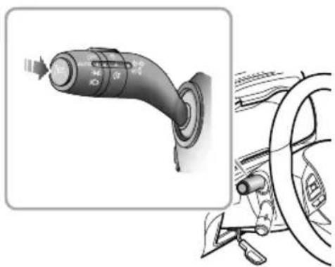
natural_image
Diagram showing a car's head and steering wheel with a rotary knob (no text or symbols)Having turned the laned departure preventionsystem on in the infotainment display, press the button at the end of the indicator stalk switch (asshown above). Thelane departure preventionsystem will enter the stand by or active state. The system default to the last selected state from when the START/STOPS switch was ON/RUNNING.
Whenthelanedeparturepreventionsystemisinthe standbyoractivestate,youcantemporarilydisable the functionbypassingthebuttonattheendoftheindicator stalkswitch(asshownabove).Pressingthebuttonagain willresumethefunction.
Whenthelanedeparturepreventionfunctionis
enabled,theindicatorlampilluminatesyellow.Whenthe functionisenabledandthevehiclespeedisabove37mph (60km/h),theindicatorlampremainsgreen.Whenthe functionisdisabled,thesystemindicatorlampextinguishes andthemessagecentreintheinstrumentpackdisplaysa promptmessage.Ifthelanedeparturepreventionsystem detectsafaultorfailure,theindicatorlampwillflashyellow for90s,andthenremainon.
Thelanedeparturepreventionsystemwillbe impairedinthefollowingconditions:
Thesystemdetectsthatthedriverhasnotmovedthe steeringwheelforapresettimeperiod.
Duringsysteminterventionthesteeringwheelisturned intheoppositedirection.
Thefrontviewcameraisobstructedoritisimpossible forthecameratodetectthelanelineaheaddueto weatherandenvironmentalfactors.
Thelanelineistoothin,damaged,orfuzzy.
The vehicle is driven on the bend with a small curvature radius.
Thewidthoftheroadistoonarrowortoowide.
The vehicle is driven on a road section without lane lines.
The vehicle has just entered a road section with lane lines.
Thevehiclechangeslanes.
ThevehicleisnotinD.
The vehicleswayslaterallytoofast.
STARTING&DRIVING
•Thevehiclespeedisbelow33mph(55km/h),orabove 93mph(150km/h).
•Theanti-lockbrakesystem(ABS)andthedynamic stabilitycontrolsystem(SCS)areactivated.
- Faultsexistintheanti-lockbrakesystem(ABS), dynamic stabilitycontrolsystem(SCS), electricpowersteering system(EPS), etc.
IMPORTANT
Thelanedeparturepreventionsystemwillnotoperate inthefollowingsituations:
- Thedriver indicates in the direction of the helaneline about to be crossed.
•Thehazardlampsareactivated.
• Thedriverappliestheacceleratorrapidly,carries outanemergencymanoeuvreormakesahardbrake pedalapplication.
IMPORTANT
• Incaseswherethenumberoflanesincreaseor lanesmergethedriverMUSTtakefullcontrolofthe vehicle.
• Inareaswheretherearecomplextrafficconditions suchasintersectionsorroadjunctionswith congestion, thedriverMUSTtakefullcontrol.
Itisrecommendedtoturnoffthelanedeparture preventionsysteminthefollowingsituations:
- Drivinginasportsstyleormanner.
- Drivinginbadweatherconditions.
- Drivingonroughorpoorroadsurfaces.
- Drivingthroughroadworksorconstructionsites.
LaneKeepingAssistSystem(LKA)

Thelanekeepingassistsystemisanauxiliary systemthatprovidesassistancetothedriver. ItdoesNOTremovetheresponsibility of safedrivingfromthedriver. Whenchoosing tousethelanekeepingassistsystem, the driverMUSTalwayspayattentiontothe surroundings, holdthesteeringwheelandbe preparedtomakemanoeuvresatanytime. Failuretomaintainoverallcontrolofthe vehiclemayresultinanaccidentorpersonal injury.

Thelanekeepingassistsystemdoesnot alwaysrecognisethelaneline.Sometimes poorroadsurfaces,certainroadstructures orobjectsmaybemistakenforlanelines. Whensuchsituationsoccur,thelanekeeping assistsystemmustbeimmediatelyturnedoff.
Thelanekeepingassistsystemusesthefrontviewcamera todetectthelanelinesaheadofthevehicle.Thesystem
willoperatewhenthefollowingdetectionconditionsare met:
•ThefunctionisswitchedON.
•Vehiclespeedisabove37mph(60km/h).
•Lanelinemarkingsareclear.
Aslongasthesystemrecognisestwolanelineson bothsidestheindicatorlampintheinstrumentpack willilluminategreen. Thesystemwillalwaysattempt to maintainthevehiclepositioninthecentreofthelane byusingcorrectivesteeringintervention of thevehicle deviatesfromthelanelinesthesystemwillactivatethe lanedeparturewarningfunctiontoalertthedriverthat thevehiclehasdeviatedfromthelan. Thedrivercan takecorrectiveactionatanytin. Thefunctionwill automaticallyexitwhenthevehiclespeeddropsbelow 33mph(55km/h).
Intheabsenceofasteeringinputfromthedriverforsome seconds,anacousticwarningisprovided,theinstrument packprovidesayellowprompt.lfthesystemstillfailsto seeaninputfromthedriver,theacousticwarningbecomes continuousandthepromptilluminatesred.lfthesystem stillfailstodetectaninputfromthedriver,itwillassume
STARTING&DRIVING
thedriverisnotabletokeeptheirhandsonthesteering wheelandautomaticallyexitthefunction.Accompaniedby theexit,amoreurgentacousticwarningisprovidedforat least5soruntilthedriverholdsthesteeringcontrolagain.
Lanekeepingassistsystemsetting
Theoperatinginterfaceforthelanekeepingassistsystem islocatedintheinfotainmentdisplay.Enterthevehicle settinginterfacetolocatethedrivingassistoption,scroll acrossthepagetofindthesettinginterfaceforthelane assistsystem:
IT ouchthecorrespondingbuttonintheinfotainment displaytoturnon/offthelaneassistsystem.Select lanekeepingintheassistmodetoswitchonthelane keepingassistsystem.Thesystemdefaultstothelast selectedstatefromwhentheSTART/STOPSwitchwas ON/RUNNING.
2T ouchthecorrespondingbuttonintheinfotainment displaytoturnon/offtheaudiblealert.Thesystem defaultstothelastselectedstatefromwhenthe START/STOPSwitchwasON/RUNNING.
3T ouchthecorrespondingbuttonintheinfotainment displaytoadjustthealertsensitivity.Thesystem defaultstothelastselectedstatefromwhenthe START/STOPSwitchwasON/RUNNING.
4T ouchthecorrespondingbuttonintheinfotainment displaytoturnon/offthevibrationalert.Thesystem defaultstothelastselectedstatefromwhenthe START/STOPSwitchwasON/RUNNING.
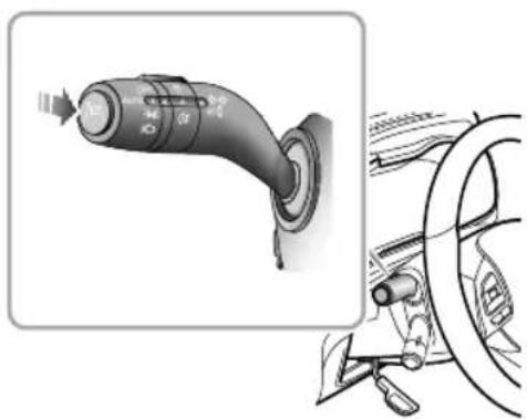
natural_image
Diagram showing a car's head and steering wheel with a rotary knob (no text or symbols)Having turned the lane keeping assistsystem on the infotainment display, press the button at the end of the indicator stalk switch (asshown above). Thelane keeping assists system will enter the stand by or active state. The system default to the last selected state from when the START/STOP switch was ON/RUNNING.
Whenthelanekeepingassistsystemisinthestandbyor activestate,youcantemporarilydisablethefunctionby pressingthebuttonattheendoftheindicatorstalkswitch (asshownabove).Pressingthebuttonagainwillresume thefunction.
Whenthelanekeepingassistfunctionis
enabled,theindicatorlampilluminatesyellow.Whenthe functionisenabledandthevehiclespeedisabove37mph (60km/h),theindicatorlampremainsgreen.Whenthe functionisdisabled,thesystemindicatorlampextinguishes andthemessagecentreintheinstrumentpackdisplaysa promptmessage.Ifthelanekeepingassistsystemdetects afaultorfailure,theindicatorlampwillflashyellowfor 90s,andthenremainon.
Thelanekeepingassistsystemwillbeimpaired inthefollowingconditions:
- Thesystemdetectsthatthedriverhasnotmovedthe steeringwheelforapresettimeperiod.
- During system intervention the steering wheel is being manipulated by the driver.
- Thefrontviewcameraisobstructedoritisimpossible forthecameratodetectthelanelineaheaddueto weatherandenvironmentalfactors.
• Thelanelineistoothin, damaged, or fuzzy.
• The vehicle is driven on the bend with a small curvature radius.
• Thewidthoftheroadistoonarrowortoowide.
•Thevehicleisdrivenonaroadsectionwithoutlane lines.
•Thevehiclehasjustenteredaroadsectionwithlane lines.
•Thevehiclechangeslanes.
•ThevehicleisnotinD.
•Thevehicleswayslaterallytoofast.
STARTING&DRIVING
•Thevehiclespeedisbelow33mph(55km/h),orabove 93mph(150km/h).
•Theanti-lockbrakesystem(ABS)andthedynamic stabilitycontrolsystem(SCS)areactivated.
- Faultsexistintheanti-lockbrakesystem(ABS), dynamic stabilitycontrolsystem(SCS), electricpowersteering system(EPS), etc.
IMPORTANT
Thelanekeepingassistsystemwillnotoperateinthe followingsituations:
- Thedriverindicatesinthedirectionofthelaneline abouttobecrossed.
•Thehazardlampsareactivated.
• Thedriverappliestheacceleratorrapidly,carries outanemergencymanoeuvreormakesahardbrake pedalapplication.
IMPORTANT
• Incaseswherethenumberoflanesincreaseor lanesmergethedriverMUSTtakefullcontrolofthe vehicle.
• Inareaswheretherearecomplextrafficconditions suchasintersectionsorroadjunctionswith congestion, thedriverMUSTtakefullcontrol.
Itisrecommendedtoturnoffthelanekeepingassistsystem inthefollowingsituations:
- Drivinginasportsstyleormanner.
- Drivinginbadweatherconditions.
- Drivingonroughorpoorroadsurfaces.
- Drivingthroughroadworksorconstructionsites.
MGPilotSystem \*

TheassistanttechnologyusedintheMG pilotsystemcannotreplacethdriver's judgmentontheroadandtrafficconditions. Thesystemcanprovideassistanceforthe driverbutcannotreplacethdriverindriving. WhenchoosingtousetheMGpilotsystem, duetothelimitationsofsystemdetection andcontrol,thedrivermustalwaysbe careful.Failureretomaintainoverallcontrol ofthevehiclemayresultinanaccidentor personalinjury.

TheMGpilotsystemisadriverassistance function, it'snotautopilot. Therearemany situationswherethefunctionisrestrictedor exits. Thedriverneedstoholdthesteering wheelatalltimesandcorrectortakeover thesteeringwheelcontrolifnecessary.
TheMGpilotsystemneedstobeusedinconjunctionwith theadaptivecruisecontrolsystem. TheMGpilotsystem
worksonthebasisoftheadaptivecruisecontrolsystem. Ifthelanelinesaheadonbothsidesareclear,thesystem canassistthevehicleindrivingwithinthelanelines.When drivingataspeedlowerthan37mph(60km/h),ifthereisa vehicleaheadandthelanelinesaheadonbothsidesaren't clear,thesystemalsocanassistthevehicleinfollowingthe trackofthevehicleahead.
Note: Thedrivers should adjust the vehicles speed and the following distance according to other advisability, weather and road conditions. The MG pilot system does not respond topedestrians, animals, stationary vehicles and vehicle that drive across the lane or oncoming vehicles in the MG pilot system cannot reduce the vehicles speed adequately, the driver MUST apply the brakes congested conditions, should another vehicle cut into the lane being used by the vehicle under MG pilot control, the system may not detect the vehicle inadequate time to make abraking manoeuvre. In this case the brakes should be applied by the driver.
Intheabsenceofasteeringinputfromthedriverforsome seconds,anacousticwarningisprovided,theinstrument
STARTING&DRIVING
packprovidesayellowprompt.Ifthesystemstillfailsto seeaninputfromthedriver,theacousticwarningbecomes continuousandthepromptilluminatesred.Ifthesystem stillfailstodetectaninputfromthedriver,itwillassume thedriverisnotabletokeeptheirhandsonthesteering wheelandautomaticallyexitthefunction.Accompaniedby theexit,amoreurgentacousticwarningisprovidedforat least5soruntilthedriverholdsthesteeringcontrolagain.
Note: Whenthedriverusesthisfunctiontofollow thetrackofthevehicleinfront,thedriverMUSTpay attentiontothesurroundingenvironment. Overall responsibilityfordirectionandbrakingofthecar remainswiththedriver.
MGpilotsystemsetting
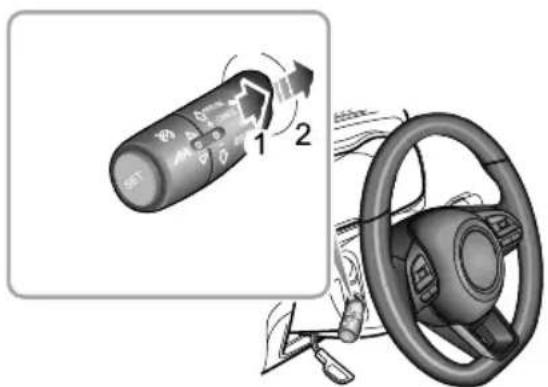
text_image
Diagram showing car climate control panel with directional arrows and steering wheel, labeled with numbers 1 and 2.TheoperatinginterfacefortheMGpilotsystemislocated intheinfotainmentdisplay.Enterthevehiclesetting interfacetolocatethedrivingassistoption,scrollacross thepagetofindthesettinginterfacefortheMGPilot system.Thedrivermayselecttoturniton/off.T ouse theMGpilotsystem,theadaptivecruisecontrolsystem mustbeturnedonatthesametime.Whenthefunction
isturnedoff, themessagecentreintheinstrumentpack willdisplaythecorrespondingprompt.
T urntheadaptivecruisecontrollevelto"RESUME"twice willswitchtheMGpilotsystemfromstandbytoactive state.
WhentheMGpilotfunctionisenabled,the indicatorlampilluminatesyellow.Whenthefunctionis active,theindicatorlampilluminatesgreen.Whenthe functionisdisabled,thesystemindicatorlampextinguishes andthemessagecentreintheinstrumentpackdisplaythe promptmessage.IftheMGpilotsystemdetectsafaultor failure,theindicatorlampwillflashyellowfor90s,andthen remainon.
T echnicalrequirementsforusingMGpilot system:
•Theadaptivecruisecontrolsystemmustbeactivated.
•TheMGpilotsystemmustbeswitchedonviathe correspondingbuttonintheinfotainmentsystem.
thehehiclespeedbelow7mp(60km/h)the systemmustbeabletodetectandinesonbothsides ofthevehicleoratargetvehicledirectlyahead.
- If the vehicles speed is greater than 37 mph (60 km/h), the system must be detected and also besides of vehicle.
•The vehicle is in D.
TheMGpilotsystemwillbeimpairedinthe following conditions:
The system detect shath elrive has not moved the steering wheel for apresett time period.
- During system intervention the steering wheel is being manipulated by the driver.
- ThetechnicalrequirementsforMGpilotsystemarenot met.
- Thefrontviewcameraisobstructedoritisimpossible forthecameratodetectthelanelineaheaddueto weatherandenvironmentalfactors.
• Thelanelineistoothin, damaged, or fuzzy.
•Thevehicleisdrivenonthebendwithasmallcurvature radius.
STARTING&DRIVING
• Thewidthoftheroadistoonarrowortoowide.
• The vehicle is driven on a road section without lane lines.
• The vehicle has just entered a road section with lane lines.
•Thevehiclechangeslanes.
•ThevehicleisnotinD.
•Thevehicleswayslaterallytoofast.
• The vehiclespeed is below 33 mph (55 km/h), or above 111 mph (180 km/h).
•Theanti-lockbrakesystem(ABS)andthedynamic stabilitycontrolsystem(SCS)areactivated.
- Faultsexistintheanti-lockbrakesystem(ABS), dynamic stabilitycontrolsystem(SCS), electricpowersteering system(EPS), etc.
ItisrecommendedtoturnofftheMGpilotsysteminthe followingsituations:
- Drivinginasportsstyleormanner.
- Drivinginbadweatherconditions.
- Drivingonroughorpoorroadsurfaces.
- Drivingthroughroadworksorconstructionsites.
- Drivingthroughcomplicatedroadsections(suchas urbansitesandintersections).
- Drivingonsteepofexcessivelywindingroadsinlow visibility.
- Drivingongrasstracksorunpavedroads.
IMPORTANT
The MGpilotsystemwillnotoperateinthefollowing situations:
• Thedriverindicates.
•Thehazardlampsareactivated.
• Thedriverappliestheacceleratorrapidly,carries outanemergencymanoeuvreormakesahardbrake pedalapplication.
IMPORTANT
• Incaseswherethenumberoflanesincreaseor lanesmergethedriverMUSTtakefullcontrolofthe vehicle.
• Inareaswheretherearecomplextrafficconditions suchasintersectionsorroadjunctionswith congestion,thedriverMUSTtakefullcontrol.
• ThedriverMUSTbeawareofthesurroundingsand beabletoassumefullcontrolofthevehiclewhen usingtheMGpilotfunctionotrackthecarinfront shouldtheneedarise.
ForwardCollisionWarningSystem(FCW)

The drivers should pay full attention and drive carefully even if the vehicle is equipped with the forward collision warning system.
Theforwardcollisionwarningsystemdetectsother vehiclesandpedestriansaheadusingtheforwarddetection radarandfrontviewcamera.Whenthespeedisabove 18mph(30km/h)andthevehicleisapproachingthevehicle orpedestrianaheadrapidly,thesystemwillpromptthe drivertoslowdownintimeandkeeparelativelysafe distancefromthevehicleorpedestrianaheadbyemitting anaudiblealertanddisplaygapromptintheinformation messagecentreintheinstrumentpack.
Note: Whenthevehiclespeedisbetween 18 and 52mph(30and85km/h), stationarytargetscanbe detected. Whenthevehiclespeed between 18 and 93mph(30and150km/h), movingtargetscanbe detected. Whenthevehiclespeedibetween 18 and 39mph(30and64km/h), pedestrianscanbedetected.
STARTING&DRIVING
Forwardcollisionwarningsystemsetting
Theoperatinginterfacefortheforwardcollisionwarning systemislocatedintheinfotainmentdisplay.Enterthe vehiclesettinginterfacetolocatethedrivingassistoption, scrollacrossthepagetofindthesettinginterfaceforthe forwardcollisionsystem.
IT ouchthecorrespondingbuttonintheinfotainment displaytoswitchtheforwardcollisionsystemon/off. Selectalertintheassistmodetoactivatetheforward collisionwarningsystem.WhentheSTART/STOP SwitchisON/RUNNING,theswitchdefaultsto ON.Whenthedriveractivelyselectstoturnoff thefunction,thepromptmessagewillbedisplayed intheinformationmessagecentreintheinstrument pack,andtheconfirmationmessagepopupinthe infotainmentdisplay.
2T ouchthecorrespondingbuttonintheinfotainment systemtoadjustthealertsensitivity.Thesystem defaultstothelastselectedstatefromwhenthe START/STOPSwitchwasON/RUNNING.
Thelampilluminatesyellowwhentheforward
collisionwarningsystemisturnedoffordetectsafaultor failure.
Theforwardcollisionwarningsystemwillbe impairedinthefollowingconditions:
- Thefrontviewcameraisobstructedoritsperformance isaffected.
•Thevehicleisdrivingonabendwithasmallcurve radius.
•Thevehicleaheadisofanonstandardtype,oronlythe sidecanbedetected.
The ehichealsbargerlosemaking impossibletomakeoutthecompleteoutline.
•Thevehicleisonanexcessivegradientorslope.
•ThevehicleisinR(AT)orReverse(MT).
•Thevehicleisacceleratingorbrakingexcessivelyhard.
- Thereareanimals,signposts,guardrails,buildingsor similarnonmotorisedobjectsahead.
STARTING&DRIVING
AutomaticEmergencyBrakingSystem (AEB) and AutomaticEmergencyBraking System for Pedestrians (AEBP)

Thedriverremainsresponsibleforthe safetyoftheentiredrivingprocess,even ifthevehicleisequippedwithautomatic emergencybrakingsystemandautomatic emergencybrakingsystemforpedestrians. ThedriverMUSTpayfullattentionand drivecarefully.Asdriverassistsystems,the automaticemergencybrakingsystemand automaticemergencybrakingsystemfor pedestrianscannotpreventaccidentsor avoidcollisionsinallsituations. Thedriver MUSTalwaysremainincontroltoavoid accidentsoremergencysituations.

Emergencybrakingwhilstunderthecontrol oftheautomaticemergencybrakingsystem andautomaticemergencybrakingsystem forpedestriansmaycauseinjuriestothe passengertherefore,drivecarefullyand allpassengersMUSTwearseatbeltsatall times.

Ensure the automatic emergency braking system automatic emergency braking system for pedestrians or vehicle powers system is switched off when being towed. If automatic emergency braking system and automatic emergency braking system for pedestrians is enabled when the vehicle is being towed, adverse effects may affect the safety of your vehicle, the towing vehicle and the people around.
STARTING&DRIVING

To avoid the occurrence of accidents, never specially test the function of automatic emergency brakingsystem and automatic emergency brakingsystem for pedestrians.
Whentheswitchfortheautomaticemergencybraking systemintheinfotainmentdisplayisON,thesystemwill detectandmonitorthevehicleaheadinthesamelanewith theforwarddetectionradarandfrontviewcamera.When thesystemdetectsthatthereisariskofcollisionbetween thevehicleandthevehicleahead,thebrakesystemwill automaticallyintervenetodeceleratethevehicle,soasto avoidcollisionaccidentsormitigatedamagefromcollision accidents.Ifthevehicleisbrakedandstopped,itwill remainstationaryforabout2s.Thenthecontrolofthe vehiclewillbehandedovertothedriver.
Whentheswitchfortheautomaticemergencybraking systemforpedestriansintheinfotainmentdisplayisON, thesystemwilldetectandmonitorthepedestriansahead inthesamelanewiththeforwarddetectionradarandfront viewcamera.Whenthesystemdetectsthatthereisarisk ofcollisionbetweenthevehicleandthepedestrianahead,
thebrakesystemwillautomaticallyintervenetodecelerate thevehicle,soastoavoidcollisionaccidentsormitigate damagefromcollisionaccidents.Ifthevehicleisbraked andstopped,itwillkeepstationaryforapprox.2s,then thecontrolofthevehiclewillbehandedovertothedriver.
Note: Whenthevehiclespeedisbetween2and52mph (4and85km/h), stationarytargetscanbedetected. Whenthevehiclespeedisbetween2and93mph(4and 150km/h), movingtargetscanbedetected. Whenthe vehiclespeedisbetween2and39mph(4and64km/h), pedestrianscanbedetected.
IMPORTANT
- Forstationarytargetations cannot completely voided the hexichapeid greater than 27 mph (45 km/h).
- Formovingtargets,collisionscannotbecompletely avoided whether relativ speed greater than 27mph(45km/h).
The automatic emergencybrakingsystemandautomatic emergencybrakingsystemforpedestrianswillonlybe activatedifthefollowingconditionsaremet:
- Thedynamicstabilitycontrolsystem(SCS)andtraction controlsystem(TCS)arefault-freeandON.
•ThevehicleisinDorN.
•Theairbagsarenotdeployed.
Note: In some cases, the driver may no have anticipated any braking intervention and does not want to apply the brakes whilst the automatic emergency brakingsystem and automatic emergency brakingsystem for pedestrians are braking heavily. The driver can temporarily cancel this operation by heavily pressing the accelerator pedal after ensuring that it is a fetodoso.
Automaticemergencybrakingsystem and automaticemergenbyakingstefor pedestrianssetting
TheoperatinginterfaderthAEB/AEBPsystemis locatedintheinfotainmentdisplay.Enterthevehicle settinginterface colocatethdrivingassistoption,scroll across the page of finding the setting interface for the forward collision system:
IT ouchthecorrespondingbuttonintheinfotainment systemtoswitchtheforwardcollisionsystemon/off. Selectemergencybrakingthessismodetactivate theautomaticemergencybrakingsystem.Whenthe START/STOPSwitchisON/RUNNING,theswitchof thesystemdefaultstoON.Whenthedriveractively selectstoturnoffthefunction,apromptmessagewill bedisplayedintheinformationmessagecentreinthe instrumentpackandapopupmessagewillappearin theinfotainmentdisplay.
2T ouchthecorrespondingbuttonintheinfotainment systemtoswitchtheautomaticemergencybraking systemforpedestrianson/off:WhertheSTART/STOP SwitchisON/RUNNING,theswitchdefaultsto ON.Whenthedriveractivelyselectstoturnoff the functionpromptmessagewibdisplayed the informationmessagecentreintheinstrumentpack andapopupmessagewillappearintheinfotainment display.
STARTING&DRIVING
Note: DONOToperateanyinfotainmentswitches whilstdriving. If you wishtomakeanysettings changes please pulloverwhenitissafeandlegaltodoso.
The indicator lamp illuminates yellow when theautomaticemergencybrakingsystemoremergency brakingsystemforpedestriansisturnedoffordetectsa faultorfailure.
Theoperationoftheautomaticemergency brakingsystemandautomaticemergency brakingsystemforpedestriansmaybeimpaired inthefollowingsituations:
- Thedetectionperformanceofforwarddetectionradar orfrontviewcameraisaffected.
•Thecontourofthevehicleaheadisunclear,for exampleatersprayedbythewheelsofthefront andsurroundingvehiclesinheavyrain/sprayorsnow conditions. - Whendrivingonspecialroadconditions,forexample, onacurveoraslope,onthesectioncomingon/offthe
bridge,avehicleahead,anoncomingvehicle,avehicle crossingtheintersection,avehiclemakingaturn,the sideofavehicleoravehiclejumpingthequeuerapidly inashortdistanceisdetected.
- There are vehicles running in the opposited direction in the lane, or the vehicle itself runs in opposite direction.
•Thevehicleaheaddoesnothaveorhasobscuredtail lampswhendrivingatnightorinatunnel;thetaillamps ofthevehicleaheadareallLEDstriplightsorother homemadecolouredlamps;inconsistentorflickering streetlightswhendrivingatnight.
•Thevehicleaheadisanultra-largevehicleoratrailer, whichistoobigtoberecognisedbythesystem(such asatractor,atraler,atowingvehicle)
•Thevehicleaheaddoesnotfollowtherulesofdriving anfarkingthevehicleaheaddrivingorthandines; thevehicleaheadisnotinthesamelaneasyourvehicle ortheviewofvehicleaheadispartiallyobscured.
• Thepedestrianisnotdirectlyinfrontofthevehicle; thepedestrianisnotfullyvisible; thepedestrianisnot standingupright; thereareacrowdofpedestrians; the
STARTING&DRIVING
pedestrianisover-shadowed;thepedestrianisinthe darkoritisachildunderacertainheight,etc.
Note: Thetwosystemsfunctiononlywhenvehicle orpedestrianisdetectedinthesamelaneahead. Thesystemcannotrecogniseanyspecial-shaped groundobstacles(suchasroadblocks,isolationpiles, isolationstrips,largestonesandotherscattered objects)andanimals. Thesystemmaynotrecognize bicycles,motorbikes,smallwheeledobjects(suchas suitcases,shoppingcartsorwheelchairs),somemeans ofunusualtransportation(suchasthehorseandcart, carriagesetc.)andvehicleswithhigherchassis.
STARTING&DRIVING
LoadCarrying

DONOTexceedthegrossvehicleweight orthepermittedfrontandrearaxleloads. Failuremayresultinvehicledamageor seriousinjury.
LoadSpace

Ensure that there are seat backrests are securely latched in the upright position when loads are carried in the load space behind theseats.

Ifthebootlid(ortailgate) cannot be closed duetothetypeofcargoloaded, besureto closeallwindowsduringdriving, select the facedistributionmodeoftheaircondition, andsettheblowertomaximumspeed, so astodecreaseexhaustfumesenteringthe vehicle.
When luggage carried in the boot, always ensure heavy items are placed as low and forward as possible, so
astoavoidthecargoshiftintheeventofanaccidentor suddenstop.
Drivecarefully and avoid emergency braking or maneuvers when large or heavy items are carried.
Drivingwiththebootlid(ortailgate)openisverydangerouftheloadbeingcarriedrequiresthebootlid(ortailgate)tobeopen,pleaseensurethecargoandthebootlid(ortailgate)aresuitablysecuredandeverymeasureistakentopreventexhaustfumesenteringthevehicle.
IMPORTANT
Traffic regulations must observe the loading cargo, if the cargo extrude the load space, appropriate warning measures must be taken to warn other road users.
InternalLoading

DONOTcarryUNSECUREDEQUIPMENT,tools orluggagethatcouldmove,causingpersonal injuryintheeventofanaccident,emergency brakingorhardacceleration.

DONOTobstructthedriverandpassengers tokeeprightsittingpostureandobservation withloads.
Foldingtherearseatscanincreaseluggagespace,referto "RearSeat"in"SeatsandRestraints"chapter.
Whencargoisloadedinthevehicle,placeitataposition aslowaspossibleandensurethatitistightlysecured,soas toavoidpersonalinjurycausedbycargomovementwhen trafficaccidentsoremergencybrakesoccur.Ifthecargo hastobeputonaseat,nooneisallowedtositonthat seat.
GeneralT owingSafety
Y ourvehiclecantowatrailerifyoucarefullyobserveload limits,useapprovedequipment,andfollowthetowing guidelines.Alwayscheckloadlimitsbeforetowing.
T owingloadsinexcessofthemaximumtowingweight canseriouslyaffectvehiclehandlingandperformance,and coulddamageyourvehiclesengineanddrive-train.
Note: Exceeding any load limits advised by MGMotor UK Ltd is dangerous. Consult there recommended load limits and loading prior to any journey.
Checktheloadingofyourvehicleandtrailer carefullybeforestartingtodrive.
T railerhitchloadshouldneverexceedthelimitadvisedby MGMotorUKLtd.
Note: Excessivetowing loads reduce frontty retraction and steering control, to little trailernoseload can make the trailer unstable and cause it to say.
T owbars:OnlygenuineMGapprovedtowbarsshould befittedtoyourvehicle.Onlyusetheattachmentmethod specifiedbythevehiclemanufacturerforsecuringthe
STARTING&DRIVING
towinghitch.ContactyourauthorisedMGdealerfor moreinformation.
Safetychains: Safetychains must be used as a precautionary measures should the trailer become unintentionally unhitched. Makes sure the safety chain is securely attached to both the trailer and the vehicle prior to departure.
Altitude: Y ourenginedeliverslesspowerathigher altitude, fotovrailemountainouare you should reduce the combined vehicle and trailer weight by 10%forevery1000mofelevation.
Gradients: Where possible when owing should play out journey, avoid teegradients. Advised braketowing mass stated assumes a maximum gradient capability of 2% where possible recommended you drive on gradients less than 2% follow the trailer associations recommendations for suitable roads.
RunningperiodAvoidowingtraileduringour vehiclesfirst1000kmor625miles.
Stop/StarfunctionManually switch the Automated Stop/StarfunctionOFFwhertowingTheraileweight
canaffectyourvehiclesbrakingefficiencyifAutomated Stop/Startisactivatedonahillwhiletowingatrailer.
EmergencyInformation
270HazardWarningDevices
272eCall-SOSEmergencyAssistance
274 EmergencyStarting
276VehicleRecovery
280TyreRepair
287 FuseReplacement
294BulbReplacement
EMERGENCYINFORMATION
HazardWarningDevices
HazardWarningLamps
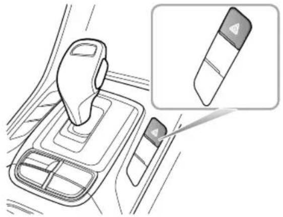
natural_image
Interior view of a car gear shift lever with a close-up inset showing the lever handle (no text or symbols)Note: Before you stop a slow the vehicle in an emergency, always press the hazard warnings switch. All turnsign allamps and direction indicators will flash together to warn other road users when your vehicle is
causinganobstructionorisinahazardoussituation. Remembertoswitchthemoffbeforedrivingaway.
WarningT triangle
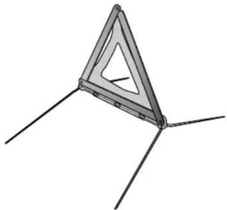
natural_image
3D diagram of a triangular structure with three legs and internal cutouts, no text or symbols presentThe warning triangles supplied with your vehicle is stowed in the load space.
If you havetostopy our vehicle on the road in an emergency, you must place a warning triangle
EMERGENCYINFORMATION
approximately50—150metresbehindthevehicle,if possible,towarnotherroadusersofyourposition.
EMERGENCYINFORMATION
eCall-SOSEmergencyAssistance
Inanaccident, your vehicle'seCall–SOSEmergency Assistancecaneitherbetriggeredmanuallyorinsevere casesautomaticallyupondetectionbyvehicle'ssensors.
TheeCallserviceisapublicserviceofgeneralinterestand isaccessiblefreeofcharge.Theemergencycallcentrewill establishverbalcommunicationwiththevehicleoccupants inordertounderstandtheextentoftheemergency and thelevelofassistancerequired.Ifverbalcommunication isnotachievableanattemptwillbemadetosendthe followingvehicleinformationmessagetotheemergency callcentre.Theappropriateemergencyserviceswillbe deployedtothevehicle'scurrentlocationifknown.
•Currenttime,locationanddirectionoftravel
•Vehicletype
•Vehicleidentificationnumber(VIN)
- Whetherthecallwasautomaticallyormanuallyinitiated
•Vehiclecategory
This system will ensure that your personal data is securely protected. It is designed to ensure that it is not traceable and other external systems are not available. When
theeCalltriggers, thesystemwillonlytransmitthedata informationtotherelevantpublicsafetyansweringpoints designatedbytherespectivepublicauthoritiesofthe countryonwhichterritorytheyarelocated,whichwill receiveandprocessyouremergencycallrequest.The systemwillretaindatalocallywithin13hoursoftriggering.
You havetherighttoaccessthedatainformationstored in this system, and to request therectification, erasure or blocking of data information that does not meet the requirements of the regulation. When you think your personal data is infringed, you havetheright to complain to the competent dataprotection authority.
Formanualactivation, pressandreleasetheSOSbutton intheoverheadconsolefor I secondtoactivatean emergencyservicescall. Asinglebeepwillbeheardwhen theeCallistriggeredandamessagewillbedisplayedon thevehicle'smessagecentreandentertainmentplayer. The entertainmentplayerwillbemutedwhilsttheemergency servicescallisactManuallytriggeredemergency servicescallsmaybecancelledbypassingandreleasing theSOSbuttonagainwithin5secondsoftheinitialpress, twobeepswillbeheardconfirmingthattheemergency
EMERGENCYINFORMATION
servicescallhasbeencancelledandthemessageswillbe removed.
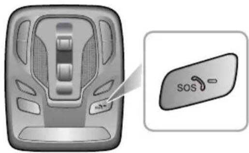
text_image
SOSflashslowlyifafaultisdetected.Faultsdetectedduringthe self-testwillbedisplayedonthevehiclesmessagecentre.
Note: The operation of Call-SOSEmergency Assistancer relies on cellular coverage and maybe affected by signal outages or low signal strength.
Note: The automatic emergency services call (eCall) function may be disabled by the local MGA authorised Repairer upon request.
Theemergencyservicescall(eCall)systemwillperforma self-testwhentheignitionisturnedON.DuringaSelf-T est theemergencyservicescall(eCall)LEDstatusindicatoron theSOSbuttonwillflashquicklyuntilcompletion.TheLED statusindicatorwillbeilluminatedsolidifnosystemfaults arepresent.TheLEDstatusindicatorwillbeextinctdor
EMERGENCYINFORMATION
EmergencyStarting
UsingBoosterCables

NEVERstarttheenginebypushingortowing.

MakesurethatBOTHbatteriesareofthe samevoltage(12volts),andthatthebooster cablesareapprovedforusewith12voltcar batteries.

Ensuresparksandnakedlightsarekeptwell awayfromtheenginecompartment.
Usingboostercables(jumpleads)fromadonorbattery, orabatteryfittedtoadonorvehicle,istheonlyapproved methodofstartingacarwithaflatbattery.
If the battery from donor vehicle is to be used, the vehicle should be parked with their battery locations adjacent to one another. Ensure that the two vehicles do not touch.
StartingtheVehicle

Ensure that each boostercable connection is securely made. Theremust benorisk of the clips accidentally slipping from the battery terminals (as a result of engine vibration, for example), this could cause sparking, which could lead to fire ore explosion.
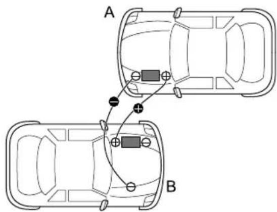
text_image
A BEMERGENCYINFORMATION
EnsuretheSTART/STOPswitchisturnedoffandswitchchoff ALLelectricalequipmentofBOTHvehicles,thenfollowthe instructionsbelow:
ConnecttheREDboostercablebetweenthepositive (+)terminalsofbothbatteries. ConnecttheBLACK boostercablefromthenegative(-)terminalofthe donorbattery(A)toagoodearthpoint(anengine mountingorotherunpaintedsurface,forexample),at least0.5mfromthebatteryonthedisabledvehicle (B).
2Check that the cables are clear of moving part so both engines, then start the engine of the donor vehicle and allow it to die for a few minutes.
3Nowstarttheengineofthevehiclewiththe dischargedbattery(DONOTcranktheenginefor morethan 10seconds).Ifthedisabledvehiclewill notstartafterseveralattemptsitmayneedobe repaired.PleasecontacttheMGAuthorisedRepairer.
4Afterboththevehicleshavenormallystarted,allow theenginestoidleformorethan2minutesbefore
shuttingdowntheengineofthdonorvehicleand disconnectingtheboostercables.
IMPORTANT
NEVERturnonanyelectricalequipmentonthe startedvehiclebeforeremovingtheboostercables.
5Disconnectingtheboostercablesmustbeanexact reversaloftheprocedureusedtoconnectthem,i.e. disconnecttheBLACKcablefromtheearthpointon thedisabledvehicleFIRST.
EMERGENCYINFORMATION
VehicleRecovery
T owingforRecovery
T owingEye

DONOTuseatowropethatistwisted-orthetowinghookmaybeunscrewed.
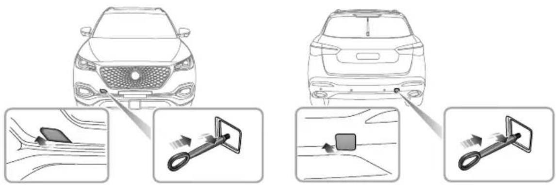
text_image
Diagram illustrating car frontview and rearview mirror system with close-ups of sensor readings and adjustment arrowsEMERGENCYINFORMATION
Y ourcarisequippedwith2towingeyes(locatedatthe frontandtherearofthevehicle),whichareusedfor fittingthetowinghookinthetoolkit.Thetoolkitis placedbeneaththeloadspacefloor.T ofitthetowinghook, removethesmallcoversetintothebumper ,thenscrew thetowinghookviathesmallholeintothethreadedhole inthebumperbeam(seeillustration).Ensurethetowing hookisfullytightened!
Note: Thesmallcoverremovedmaybesecuredtothe bumperbyaplasticcord.
Bothtowingpointsareintendedforusingbyqualified recoveryspecialiststoassistintherecoveryofyour vehiclewhenabreakdownoraccidentoccurs.Theyare notdesignedfortowingothervehicles,andmustNEVER beusedtotowatrailerorcaravan.Thevehiclecanbe towedusingatowropebutatowingbarisrecommended.
T owing

Whentowing, DONOTsuddenlyaccelerate orbrakesuddenly, this can cause accidents.
SuspendedT owing
If your vehicle need stobetowed, most qualified recovery specialists will use wheel lift equipment to suspend the vehicle. Please keep the driving wheel so off the ground. Ensure the parking brake is released, the hazard warning lamps are activated and passengers are defin the vehicle.
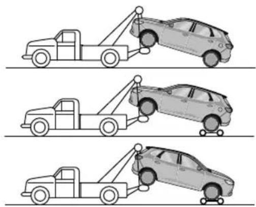
natural_image
Three line drawings of a car being towed from a pole, showing different suspension or collision scenarios (no text or symbols present)EMERGENCYINFORMATION
Four-WheelTouchdownT owing

If, duetoanelectrical fault, it is considered unsafetoswitch the start/stop switch on, the car will need to be recovered on a trailer.

Thetowingspeedofthevehiclleshall notexceed20mph(30km/h), thetowing distanceshallnotexceed30miles(50km).
If your vehicle isistowed with the four wheels on the ground, observ the following precautions:
I Operatethestart/stopswitchtotheON/RUNNING position, this will enable the brakelights, wipers and direction indicator to be operated if necessary.
2PlacetheshiftleverinNeutral(N).
3Releasetheparkingbrake.
4T urnonthehazardwarninglamps.
5Ifthetransmissionisdamagedorissubjecttoalack oflubricatingoil,DONOTtowthevehiclewithfour wheelsontheground.
6DONOTtowbackwardwithfrontwheels(drive wheels)ontheground.
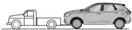
natural_image
Side view line drawing of a pickup truck and a car (no text or symbols)Withouttheengine running, greater effort will be required to operate the brake pedaland turn the steering wheel. Longer stopping distances will also be experienced.
EMERGENCYINFORMATION
T ransporter
If your vehicle need stob e shipped, as special transporter is recommended. Secure the vehicle on the transporter as follows:
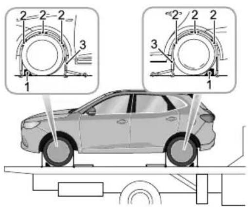
text_image
Diagram illustrating car wheel assembly with numbered components and supporting systemI Apply the parking brake, manual transmission places the shift lever in Neutral (N), automatic transmission places the shift lever in Park (P).
2Placethewheelchock(1)asshowninthefigure, thenplacetheantisliprubberpad(2)aroundthe circumferenceofthetyre.
3Fitthelashingstraps(3)aroundthewheelsandsecure tothetrailer.Tightenthestrapsuntilyourvehicleis securelyheld.
EMERGENCYINFORMATION
T yreRepair
T oolldentification(includingtyrerepair tool)
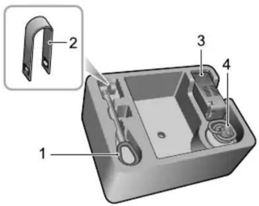
text_image
Technical diagram of a mechanical component with numbered parts labeled 1 to 4, including a magnified inset view.IT owingHook
2WheelBoltCapRemovalTool
3ElectricAirPump
4RepairFluidReservoir
T yreRepair
I Removethelabelatthebottomoftherepairfluid reservoirandattachittothesteeringwheeltoremind thedrivenotæxceed50mph (80km/h).
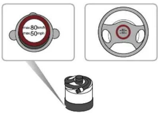
text_image
max80km/h max50mph2Connecttheairhoseoftheelectricairpumptothe repairfluidreservoir.Inverttherepairfluidreservoir onthegrooveoftheelectricairpump.Removethe valvedustcapofthedamagedtyre,andconnectthe hoseconnectoroftherepairfluidreservoirtothe
EMERGENCYINFORMATION
tyrevalve.Checkifthepowerswitchoftheelectric airpumpisoff(with"Opressed),thenconnectthe electricairpumpplugtothe12Vpowersocketinthe centreconsole,andswitchonthestart/stopswitch.
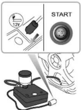
text_image
12V STARTNote: To avoid battery discharge, it is recommended to keep the engineer running.
Switchorthepowerswitchofthelectricompressor (i.e.,press-"),totartpumpingsealantintothe tyre. Thetyresealantbottlewillbecomeemptyafter approximately30seconds. Thetyreshouldreach the specifiedpressurewithin5to10minutes.
Notchpressurgaugmabrieflyreach bar(87psi),thenthepressurebeginstodropto normal.
Whether require pressure reached switch of the powerswitch of the electric compressor (i.e., press "O").
Nifrequirepressurannbe reachedwithin 10minutes, pleasedisconnectthe compressor, drivethevehicle 10metres(33feet) approxforwardorbackwardtoallowthesealant tospreadwithinthetyre. Iftherequiredpressure castillteachedtheyneverely damagedandyoushouldseekassistancefroman MGAuthorisedRepairer.
EMERGENCYINFORMATION
Note:Continueduseoftheelectricairpump formorethan 10minutesmayresultinmotor overheatanddamage.
5Removethetyresealantbottlefromtheslotinthe compressor, disconnect the hose from the they re valve, removethe compressor plug from the centre console powersocket, return the tyrerepair kit to its stowage tray.
6Aftersuccessfullyaddingsealanttothetyre,drive immediatelyforashorttime(aroundoneminute)this willallowthesealanttodistributeevenlyinsidethe tyre.Continuedrivinganddonotexceed50mph(80 km/h).Afterafurther10minutes,findasafeplaceto stopandrecheckthetyrepressure.
Pleasetakedifferentmeasuresbasedonthetyrepressure measured:
• Ifthetyrepressurehasdroppedtolessthan0.8 bar(11.6psi),donotcontinuedriving,seekanMG AuthorisedRepairerforassistanceinstead.
- Ifthetyrepressureisbetween0.8bar(11.6psi)and2.3 bar(33.3psi),connectthehoseofelectricairpumpto
thetyrevalve, and connect the plug of the electric air pumpto the powersocket, thenswitch on the electric air pumptoinflatethetyre until treachest therequired pressure. Repeat the operations of step 6 after driving a maximum distance of 3 miles (5 km).
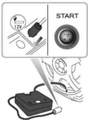
text_image
12V START- Ifthetyrepressurehasnotdropped,youmaycontinue driving,butthevehiclespeedmustnotexceed50mph (80km/h),andthedrivingmileagemustnotexceed125 miles(200km).
EMERGENCYINFORMATION
Note: DONOTremoveforeignobjects(eg.screws, nails)fromthetyre. Thetyrerepairsystemmustonly beusedwhenteforeignobjectisinthetreadpattern (A), DONOTattemptarepairwhenthedamageisin thesidewallofthetyre(B).
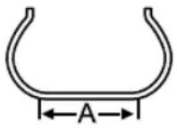
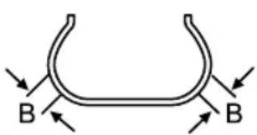
text_image
B BChangingaWheel \*
Ifyouneedtochangethewheelduringthejourney,choose asafeplacetostopawayfromthemainroadifpossible. Alwaysaskyourpassengerstogetoutofthecarandwait inasafeareaawayfromothertraffic.
Switchonhazardwarninglamps. If available, position awarning triangle about 50 to 150 metres behind your vehicle towarnapproaching traffic.
Beforechangingawheel,ensurethefrontwheelsareinthe straightaheadposition.Applytheparkingbrakeandplace thegeashifteveinPark (P).
Observethefollowingprecautions:
- Ensurethejackispositionedonfirm,levelground.
- Ifthevehiclemustbeparkedonthehill,placechocks infrontofandbehindother3wheelstoppreventthe vehiclemoving.
EMERGENCYINFORMATION
PositioningtheJack

NEVERworkbeneaththecarwiththejack astheonlymeansofsupport. Thejackis designedforwheelchangingonly!

NEVERjackthecarusinganypositionsother thanthejackingpoints.Seriousdamageto thecarcouldresult.

Avoidaccidentalcontactwithanyunderbody parts,especiallyhotexhaustsystem components.
Positionthejackonfirmlevelgroundunderthejacking pointnearestthewheeltoberemoved. Notethatthe domedheadofthejackmustfitintothecorresponding recessinthesillplate(Thereisatriangleindicatorinthe areashownbythearrowhead.Seetheillustrationbelow).
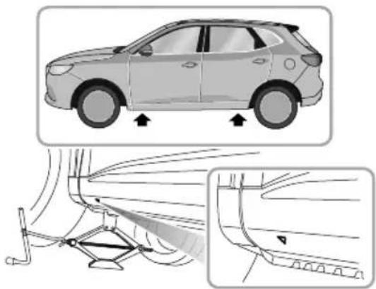
natural_image
Diagram showing a car with directional arrows indicating movement, alongside a close-up of the side profile of the car's roof structure (no text or symbols present)Turningthejackscrewhandlebyhand,adjustthejackuntil thejackheadfitssnuglyontotheflangingofthebody. Ensurethatthebaseofthejackisinfullcontactwiththe levelground.
EMERGENCYINFORMATION
FittingtheSpareWheel

Regularlycheckthesparewheeltyre pressure,itmaybeunderpressuredueto unusedforlongperiodsoftime.After replacement,atthefirstopportunitycheck andadjustthetyrepressure.

Thewheelboltsmustbetightenedtothe specifiedtorqueafterchangingawheel (120 \~ 130Nm).
Before raising the cause of special supply with the vehicle to remove each wheel bolt cap. Use the wheel bolt spanned to slackereach bol half turn anti-clockwise.
2T urnthehandleinaclockwisedirectionuntilthetyre isclearoftheground.
Removethewheelboltsanplacethinirthookit topreventhenfronbeingost Makesurthevehicle isteadynderisloisflipmovement beforeremovingwheelbolts.
4Removetheroadwheel.
NotAvoidplacingwheelsfacedownonthe ground-thesurfacemaybescratched.
5Fitthesparewheelandtightenthewheelboltswith wheeldokpanneuntthewheiseate firmly againstthehub.
Lowerthecarand-removthejacktherFULL Ytighten thewheelboltsinadiagonalsequence.
Finally return the tool to a took kit put the kit into boottighter the retaining bolt spudow the luggage carpet and put there placed wheel above the carpet (wheel rim face up).
Note: DONOTstandonthehandleofthewheelbolt spanneasextensionubonthehandlethe spanner.
Note: When replacing the wheel, please fully tighten the bolts in the diagonal sequence twice.
Note: ContactanMGAuthorised Repairertoreplace with anewtyreurgently.
EMERGENCYINFORMATION
SpacesaverSpareWheel

Onlyonespacesaversparewheelcanbeused atanyonetime,otherwisetheoperational performanceandbrakeperformancemaybe reduced,therebyleadingtoaccidentorinjury toyourselfandothers.

Whendrivingonicyorslipperysurfacesitis advisedtofitthespacesaverwheeltotherear ofthevehicletomaintinadaquatestability. Thismaymeanswappingafrontwheelwith arearwheel.

Snowchains cannot be used on the spacesaversparewheel, this can cause damage to the car and snow chain.
Whenthespacesaversparewheelisfitted,thevehicle speedshouldnotexceed50mph(80km/h).Pleasehave thefull-scaletyrerepairedandreplacethesparewheelas soonaspossible.Thiswillextendthelifespanofthespare wheelforotheremergencies.
Note: DONO Tuseanautomaticcarwashwhen thespacesaverwheelisfitted, theguiderailsofthe
cawashmayconflictwiththewheel/tyrandause damage.
EMERGENCYINFORMATION
FuseReplacement
Fuse
Fusesaresimplecircuitbreakerswhichprotectthecar's electricalequipmentbypreventingtheelectricalcircuits frombeingoverloaded.Ablownfusemaybeindicated whentheitemofelectricalequipmentitprotectstops working.
Ifafuseissuspectedfaulty,youmayremoveitfromthefuse boxandobserveifthemetalwireinthefuseisbroken.
It is recommended to have spare functions in the vehicle, which can be obtained from local MGA authorised Repairer.
IMPORTANT
- NEVERattempttorepairablownfuse.ALWA YS replaceafusewithoneofthesamerating,otherwise thefiremaybecausedduetoelectricalsystem damageorcircuitoverload.
- Ifareplacedfusefailsimmediately,pleasecontactan MGAuthorisedRepairerassoonaspossible.
FuseBox
Thevehicleisequippedwith2fuseboxes:
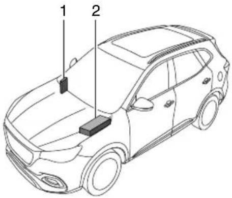
text_image
Technical diagram of a car with labeled components, showing two parts marked 1 and 2.I Passengercompartmentfusebox (behindthedriver's lowerfasciapanel)
2Frontcompartmentfusebox(nearsideoftheengine compartment)
EMERGENCYINFORMATION
Frontcompartmentfusebox
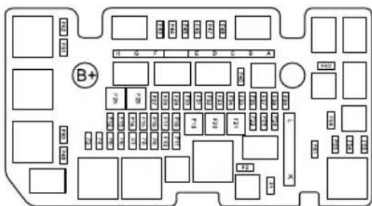
text_image
B+ G F E D C E A A B C D E F G H I J K L M N O P Q R S T U V W X Y Z A BCheckorReplaceaFuse
1T urntheSTART/STOPSwitchandallelectrical appliancesOFF, and disconnect the battery negative cable.
PressthdockcatchopentheupperoverFront compartmentfusebox.
3Holdthefuseheadwiththefuseextractiontoolinthe uppercover,pullandremovethefuse,andcheckithe fuseisblown.
Husblown;replacewithanotheruseofthesametypandsameamperovalue.
FusSpecification
| Spedes | Function | |
| F1 | - | |
| F2 | - | |
| 10AF3 | FronFogLamp | |
| BodyControModule | ||
| F5 | BodyControModule | |
| F6 | - | |
| F7 | EngineControModule | |
| F8 | - | |
| 15AF9 | Horn | |
| T5AF10ssion | GeaShiftActuator | |
| F11 | - | |
EMERGENCYINFORMATION
| CodeSpecs | Function | |
| F1225A | BodyControlModule | |
| F1325A | BodyControlModule | |
| F14-F19- | - | |
| F2030A | DC-DCConverter | |
| F2130A | DC-DCConverter | |
| F22-F23- | - | |
| F2415A | RearWiperRelay | |
| F2530A | DC-DCConverter | |
| F2625A | BodyControlModule | |
| F2710A | Windscreen/RearWindow WasherRelay | |
| F2825A | SuperLockRelay | |
| F2925A | BodyControlModule | |
| F3025A | FrontWiperRelay | |
| CodeSpecs | Function | |
| F31-F35- | - | |
| F3610A | AA/CCompressorRelay | |
| F37 | - | |
| F3815A | FuelPumpRelay | |
| F395ACrankSignal | ||
| F40-F42- | - | |
| F435A | DC-DCConverterRelay,Fuel PumpRelay,A/CCompressor Relay,ClutchPositionSensor, BrakePedwithNeutral PositionSensor,CoolingFanRelay Box | |
| F4415A | ElectroThermostat,VVT Valve-IntakeVTValve-Exhaust,UpstrcOxygen Sensor,DownstreamOxygen Sensor,CanisterShutoffValve | |
EMERGENCYINFORMATION
| CodeSpecs | Function | |
| F4510A | EngineOilControlValve,Canister ControlValve,ExhaustGas ControlValve,ReliefValve | |
| F4615A | EngineControlModule | |
| F4715A | IgnitionCoil,AirFlowSensor | |
| F48 - | - | |
| F4910A | RightHeadlamp | |
| F5010A | LeftHeadlamp | |
| F51-F56- | - | |
| MFIA80A | ElectricPowerSteeringControl Module | |
| MFB | 40A | 7-speedDualClutchT ransmission ControlModuleRelay |
| MFIC40A | DynamisStabilityControlSystem (pump) | |
| CodeSpecs | Function | |
| MFD | 40A | DynamisStabilityControlSystem(valve) |
| MFE | - | |
| MFF | 30AStarterRelay | |
| MFG | - | |
| MFH | 50ACoolingFan | |
| MFHA | engerCompartmentFuseBox | |
| MGL | ElectricVacuumPump | |
EMERGENCYINFORMATION
PassengerCompartmentFuseBox
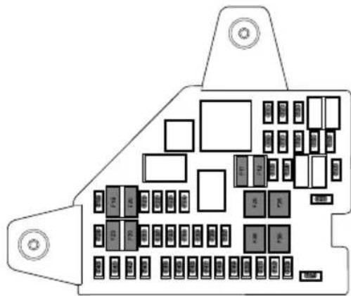
text_image
Diagram of a vehicle rear panel with labeled components and buttons, showing various internal compartments and connectors.CheckorReplaceaFuse
IT urntheSTART/STOPSwitchandallelectrical appliancesOFF, and disconnect the battery negative cable.
2Removethelowertrimpanelatdriversidetoaccess thefusebox.
3Holdthefuseheadwiththefuseextractiontoolin theFrontcompartmentfusebox, pullandremovethe fuse, andcheckifthefuseisblown.
4lfafuseisblown, replaceitwithanotherfuseofthe sametypeandsameamperevalue.
FuseSpecification
| CodeSpecs | Function | |
| F1 | 10A | SupplemenRadstrasystemDiagnosingModule, DConverter,CommunicationModulShifterControlUnInstrumentPack,BodgptModGDMAuxiliaryDisplayModule |
| 7.5AF2 | TransmissContModule,ReverserSpVitEngineControlModule | |
| 5A F3 | FraviGamModule,ForwardDetectionRadar | |
EMERGENCYINFORMATION
| CodeSpecs | Function | |
| F6-F7 - | - | |
| F815A FrontConsolePowerSocket | ||
| F95AUSBChargingPort | ||
| F10 - | - | |
| F11 | 7.5A | HeatedExteriorRearviewMirror |
| F1225A | HeatedRearWindow | |
| F13-F14 - | - | |
| F17 - | - | |
| F1830A RearLeftWindowRegulator | ||
| F195AEPBSwitch,GearDisplay | ||
| F2030A | RearRightWindowRegulator | |
| F2110A FrontRightSeatHeaterRelay | ||
| F225ADataLinkConnector | ||
| F2310A HeatedFrontLeftSeat | ||
| CodeSpecs | Function | |
| F2410A | Gateway | |
| F2530A | KLRRelay | |
| F2630A | PassengerWindowRegulator | |
| F27 - | - | |
| F285APEPSControlUnit,SpareCoil | ||
| F2910AGateway | ||
| F305A | DriverWindowCombinationSwitch,Rain/LightSensor | |
| F31 - | - | |
| F325AA | AtmosphereLampControlModule | |
| F335A | SupplementalRestraintSystemSensingandDiagnosticModule | |
| F345AC | CommunicationModule | |
| F3510A | DigitalAudioBroadcasting(DAB)Module | |
EMERGENCYINFORMATION
| CodeSpecs | Function | |
| F3610A | ElectronicSteeringColumnLockControlModule | |
| F3720A | Driver | PowerSeatAdjustment |
| F3830A | DriverWindowRegulator | |
| F3930A | Blower | |
| F4015A | EntertainmentSystem | |
| F415AU | UpperCentreConsoleSwitch | |
| F4210A | HVAC | ControlModule |
| F435A | InstrumentPack | |
| F445AR | earDrivingAssistSystem | |
| F4530A | Sunroof | Motor |
| F465AT | yrePressureMonitoringSystem | |
| F4730A | Sunshade | Motor |
| CodeSpecs | Function | |
| F4820A | FrontPassengerPowerSeat Adjustment | |
| F4930A | PowerLiftgateControlModule | |
| F50 | - | |
| F51 | 30A | RearWindow/ExteriorRearview MirrorHeaterRelay |
| F5210A | KL15SwitchRelay | |
| F5320A | ShifterControlUnit | |
| F54 | - | |
EMERGENCYINFORMATION
BulbReplacement
BulbSpecification
| BulbT ype | |
| DippedBeamandMain Beam(lowconfiguration) | HB3SL+60W |
| FrontIndicatorLamps (lowconfiguration) | WY2IW2IW |
| FrontFogLamps | H835W |
| FrontInteriorLamps (bulbconfiguration) | W5W5W |
| ReverseLamps | W16W16W |
| LicensePlateLampsW5W | 5W |
Note: BulbHB3SL+isidentical with HB3inshape and structure, and is only superior reliability and service life.
Note: Other lightsources not included in the list are LED, which cannot be replaced individually.
BulbReplacement
Beforereplacinganybulb,ensurethattheSTART/STOP SwitchandlightingswitchesareOFFsoastoavoidany possibilityofashortcircuit.Whenreplacingthebulb, actionsshallbegentlesoasnottodamagethelamp.
Note: Only replace bulb with the sametype and specification.
Note: If the bulb glass is scratched or contaminated, it may cause the bulb cannot concentrate the light. T ake care NOT to touch the glass with your fingers; If necessary, clean the glass with methylated spirits to remove fingerprints.
Consolidation of Repair-specific replacement operation.
EMERGENCYINFORMATION
Dipped/MainBeamHeadlampBulbRenewal
1 Openthebonnet——see "Bonnet" in the "Maintenance" section.
2Disconnectthebatterynegativeterminal.
3Identifyandlocatetheheadlampbulbcoverplug,and
removeit.
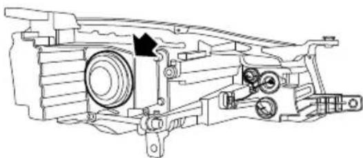
natural_image
Technical line drawing of a mechanical assembly with gears and housing (no text or symbols)4Rotatethebulbanti-clockwiseandremove.
5Removethewiringconnectorfromthebulb.
6Refitthewiringconnectortothenewbulb.
7Locatethebulbinthelamp, rotateclockwiseuntilfully secured.
8Locatethecoverplug.
9Connectthenegativebatteryterminal.
10T estheadlampoperation.
IIClosethebonnet——see“Bonnet”inthe “Maintenance”section.
EMERGENCYINFORMATION
FrontIndicatorLampBulbRenewal
I Openthebonnet——see "Bonnet" in the "Maintenance" section.
2Disconnectthebatterynegativeterminal.
3Rotatethebulbholderanti-clockwiseandremove.
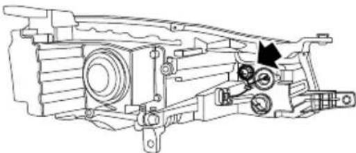
natural_image
Technical line drawing of a mechanical assembly with no visible text or symbols4Removethebulbfromtheholder.
5Installnewbulbintotheholder.
6Locatethebulbholderinthelamp,rotateclockwise untilfullysecured.
7Connectthenegativebatteryterminal.
8T estlampoperation.
9Closethebonnet——see“Bonnet”inthe “Maintenance”section.
EMERGENCYINFORMATION
FrontFogLampBulbRenewal
I Disconnect the batterynegativeterminal.
2 Safely raise and support the front of the vehicle with suitable support equipment. DONOT work under a vehicle that is only supported by ascissorortrolley jack.
3Removethebottomdeflector.
4Rotatethebulbholderanti-clockwiseandremove.
5Removethewiringconnectorfromthebulbholder.
6Refitthewiringconnectortothenewbulbholder.
7Locatethebulbholderinthelamp,rotateclockwise untilfullysecured.
8Fitthebottomdeflector.
9Connectthenegativebatteryterminal.
10T estlampoperation.
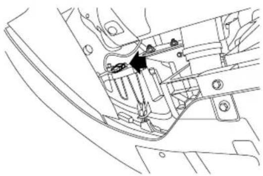
natural_image
Technical line drawing of a mechanical component with no visible text or symbolsEMERGENCYINFORMATION
ReverseLampBulbRenewal
I Disconnect the battery negative terminal.
2Forreverselampbulbreplacement,itisnecessaryto removetherearbumpercover,seekguidancefroman AuthorisedMGRepairer.
3Rotatethebulbholderanti-clockwiseandremove.
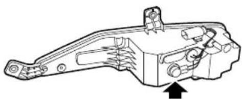
natural_image
Technical line drawing of a mechanical component with an arrow indicating direction (no text or symbols present)4Removethebulbfromtheholder.
5Installnewbulbintotheholder.
6Locatethebulbholderinthelamp, rotateclockwise untilfullysecured.
7Fittherearbumper.
8Connectthenegativebatteryterminal.
9T estlampoperation.
EMERGENCYINFORMATION
LicensePlateLampBulbRenewal
I Openandsupportthetailgate——see“Alarm Systems”inthe“StartingandDriving”section.
2Disconnectthebatterynegativeterminal.
3Removethetailgateinteriortrimpanel.
4Removethewiringconnectorofthelamp.
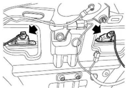
natural_image
Technical line drawing of a car engine bay with attached components and wiring (no text or symbols)5Rotatethebulbholderanti-clockwiseandremove.
6Removethebulbfromtheholder.
7Installnewbulbintotheholder.
8Locatethebulbholderinthelamp,rotateclockwise untilfullysecured.
9Refitthewiringconnector
10Fitthetailgateinteriortrimpanel.
I I Connectthenegativebatteryterminal.
12Closethetailgate.
13T estlampoperation.
EMERGENCYINFORMATION
FrontInteriorLampBulbRenewal
I Disconnect the battery negative terminal.
2Useasmallflat-bladedscrewdrivertogentlyprisethe lensfromthelampassembly.
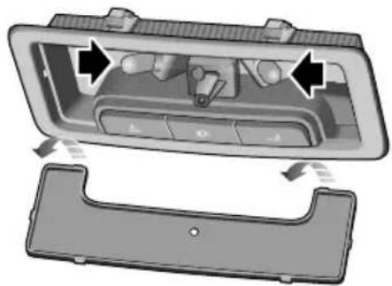
natural_image
Interior view of a car dashboard with control panel and side panel (no text or symbols visible)3Removethebulbfromitsmountingtoremove.
4Installnewbulb.
5Installthelens,locatethetwoprongsatthefront ofthelensandthencarefullyflexthelenstolocate thetwoprongsattherearofthelensintothelamp
assembly.Pushthelensupwardsuntil‘clicks’into position
6Connectthenegativebatteryterminal.
7T estlampoperation.
Maintenance
302Maintenance
306Bonnet
308 EngineCompartment
309Engine
311CoolingSystem
313 Brake
315Battery
317 Washer
319Wipers
322 Tyres
328CleaningandVehicleCare
MAINTENANCE
Maintenance
RoutineServicing
Thesafety, reliability and performance of your car will depend partly on how well it is maintained. You must ensure that maintenance is carried out when required and according to the information contained in the "Service Schedule".
Servicing
Fornextserviceinformation, pleasereferto "Message Centre" in "InstrumentsandControls" chapteror informationrelatedtoentertainmentsystem. After the completionofeachservice, thenextservicedisplaywill beresetbyyourMGAuthorisedRepairer.
Note: If a service is not carried out (orth display is not reset by the local MGA authorised Repairer after service), the serviced display cannot provide correct information
ServiceHistory
EnsureyourlocalMGAuthorisedRepairerregisterthe ServiceHistoryaftereachservice.
BrakeFluidReplacement
Replace the brake fluid according to the "Service Schedule" requirements.
Note: Brakefluidreplacementwillbeanadditional cost.
CoolantReplacement
Thengincola(anti-freezandatsolution) needstobereplacedaccordingtothe"ServiceSchedule" requirements.
Note: Coolantreplacementwillbeanadditionalcost.
EmissionControl
Y ourcarisfittedwithexhaustemissionandevaporative controlequipmentdesignedtomeetspecificterritorial andlegalrequirementscorrectenginesettingsmay adverselyaffectexhaustemissions,engineperformance
and fuel consumption, as well as causing high temperatures, which could result in damage to the catalytic converter, particulate filter and engine.
IMPORTANT
Y oushouldbeawarethatunauthorisedreplacement, modificationortamperingwithenginesettingsorthis equipmentbyanownerormotorvehiclerepairercould resultinthemanufacturer'swarrantybeingdeemedas invalid.
OwnerMaintenance

Anysignificantorsuddendropinfluidlevels, oruneventyrewear,shouldbereported withoutdelay.Forfurtherinformation,refer toanMGAuthorisedRepairer.
Inadditiontotheroutineservicesreferredtoppreviously, anumberofsimplechecksmustbecarriedoutmore frequently.Y oucanperformsuchchecksbyyourself. Adviceisgivenasfollows.
DailyCheck
•Operationoflights,horn,directionindicatorlamps,wipers,washersandwarninglights.
•Operationofseatbeltsandbrakes.
- Lookforfluiddepositsunderneaththecarthatmight indicatealeak.
- Checktyreappearance.
WeeklyCheck
- Engineoillevel.
- Coolantlevel.
- Brakefluidlevel.
•Windscreenwasherfluidlevel.
•Operateairconditioning.
Not: hengine level should be checked more frequently if the car is driven for prolonged periods at high speeds.
SpecialDrivingConditions
If your car is frequently used industry conditions, or operated in extreme climates where sub-zero or very high ambient temperatures are normal, more frequent attention may need to be paid to servicing requirements.
MAINTENANCE
Y ouneedtocarryoutspecialmaintenanceoperations (refertoServicePortfolioorcontactyourMGAuthorised Repairer).
SafetyintheGarage

Coolingfansmaycommenceoperatingafter theengineisswitchedoff,andcontinue operatingforanumberofminutes.Keep clearofallfanswhileworkingintheengine compartment.
If you need to carry out maintenance, observe the following safety precautions at all times:
- Keepyourhandsandclothingawayfromdrivebeltsand pulleys.
- If the car has been driven recently, DONOTTOUCH exhaust and cooling system components until the engine has cooled.
DONOTOUCH-electrical lead components while the engine is running, or with the START/STOP Switchon.
- NEVERleavetheengine running in an unventilated area -exhaust gases are poisonous and extremely dangerous.
DONO Workunderneattheawithheel changingjackastheonlymeansofsupport.
- Ensurethatsparksandnakedlightsarefarawayfrom theenginecompartment.
- Wearprotectiveclothingandworkgloves.
- Removewatchesandjewelrybeforeworkinginthe enginecompartment.
- DONOTallowtoolsormetalpartsofthecartomake contactwiththebatteryleadsorterminals.
ToxicLiquid
Fluid used motovehicular poisonou and should not consumed brought into contact with open wounds. These include: battery acid, coolant, brake fluid, fuel, engine oil and windscreen washer fluid.
FoyouvsafetALWA YSakobayl instructionsprintedonlabelsandcontainers.
MAINTENANCE
UsedEngineOil
Prolongedcontactwithengineoilmaycauseseriousskin disorders,includingdermatitisandcanceroftheskin.
Washthoroughlyaftercontact.Usedengineoilshould bedisposedofcorrectly.Incorrectdisposalcancausea threattotheenvironment.
MAINTENANCE
Bonnet
OpeningtheBonnet

DONOTdrivewhenthebonnetisopenor retainedonlybythesafetycatch.
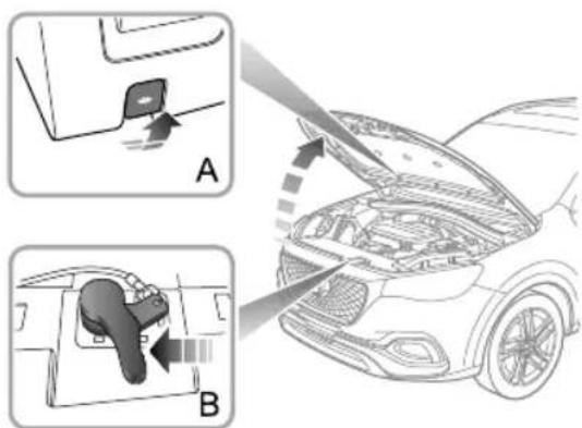
text_image
Diagram illustrating car door opening process with labeled parts A and B, showing tool placement and assembly stepsI Pullthebonnetreleasehandle(A)fromtheinsideof thecar.
2Pushthelever(B)mountedonthebonnetinthearrow directiontoreleasethebonnetsafetycatch.
3Raisethebonnettoopenit.
ClosingtheBonnet
Holdthebonnetusingbothhandsandlowerit,allowingit todropforthelast20 \~ 30cmtofullyclosethebonnet.
Byattemptingtoliftthefrontedgeofthebonnet,check ifthelockisfullyengagedafterclosingthebonnet.Ifitis notfullyengaged,pleasereopenthebonnetandrepeatthe closingaction.
BonnetOpenAlarm
Ifthebonnetisnotfullyengaged,whentheSTARTSTOP switchisintheONposition,thecorrespondingalarmicon (referto"MessageCentre"in"InstrumentsandControls" chapter)willbeshownonthemessagecentredisplay.Ifitis detectedthatthebonnetisnotfullyengagedwhiledriving,anaudiblewarningwillsound.
IMPORTANT
- Forsafetyreasons,thebonnetshouldbeclosed wellwhendriving.Thereforeyoumustcheckafter closingthebonnetthatthebonnetissecurely latched,e.g.thebonnetedgeisflushwiththebody ofthecar.
• Y oushouldstopthecarimmediatelywhensafety permitsandclosethebonnetifitisnotclosedfully whendriving. - Bewareofinjurytohandswhilefullyclosingthe bonnetwithadownwardforce.
MAINTENANCE
EngineCompartment

While working in the engine compartment, always observethes safety precautions listed under "Safety in the Garage". Referto "Maintenance" in "Maintenance" section.
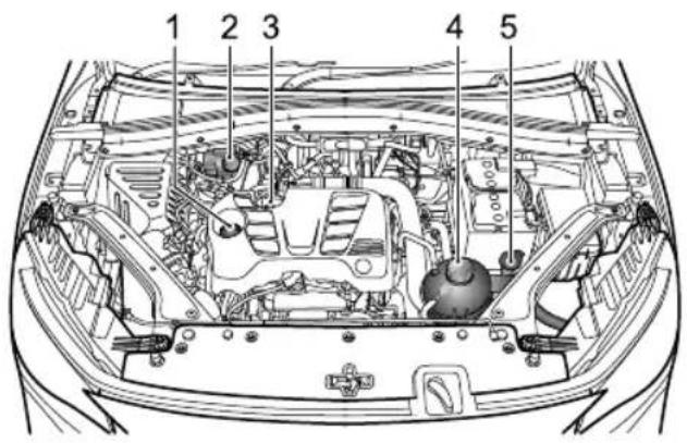
text_image
1 2 3 4 5I Engineoilfillercap(blackcap)
2Brakefluidreservoir(yellowcap)
3Engineoildipstick(yellow)
4Coolantreservoir(blackcap)
5Washerfluidreservoir(bluecap)
Engine
1.5LT urbochargedEngineOil
ACEAClassificationofEngineOils
EuropeanAutomobileManufacturersAssociation(ACEA) will classify the engine oils based on performance and quality. To ensure the best performance of the vehicle, please only use engine oil that a recommended by the manufacturer (see "Technical Data" - 'Recommended Fluids and Capacities'.
If you are operating the vehicle in extreme temperature conditions please consult your MGA authorised Repairer for advice.
EngineOilLevelCheckandT opUp

DrivingthecarwiththeoillevelABOVEthe uppermark,orBELOWthelowermarkon thedipstick,willdamagetheengine.T ake caretoavoidspillingengineoilontoahot engine-Spillagesmayresultinafire!
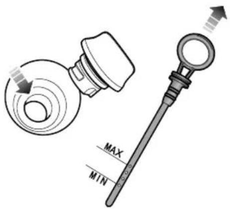
text_image
MAX MIN1.5LT urbochargedEngine
MAINTENANCE
Checktheoillevelweeklyandtopupwithoilwhen necessary. Ideally, theoillevelshouldbecheckedwiththe enginecoldandthecarrestingonlevelground. However, iftheengineisrunningandalreadygettingwarm, waitfor atleastfiveminutesafterswitchingofftheST ART/STOP switchbeforecheckingthelevel.
I Withdrawthedipstickandwipethebladeclean.
2Slowlyinserttheoildipstickandpullitoutagainto checktheoillevel;theoillevelshallnotbelowerthan the'MIN'markontheoildipstick.
3Unscrewtheoilfillercapandrefilltheoiltomaintain theoillevelbetweenthe'MAX'markand'MIN'mark ontheoidipstick.
4Waitfor5minutesandthenrechecktheoillevel, addingmoreoilifnecessary—DONOTOVERFILL!
5Finally,ensurethedipstickandfillercaparereplaced.
EngineOilSpecification
Usetheengineoilrecommendedandapprovedby themanufacturer.Referto"RecommendedFluidsand Capacities"in"TechnicalData"chapter.
Note: DONOTuseanyoiladditives.
IMPORTANT
Checktheengineoilmorefrequentlyifthecarisdriven athighspeedsforprolongedperiods.
CoolingSystem
CoolantCheckandT opUp

DONOTremovetheenginecoolantreservoir capwhenthecoolingsystemishot-escaping steamorhotcoolantcouldcauseserious injury.
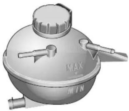
natural_image
3D rendered image of a mechanical component with no visible text or symbolsIt is recommended that the cooling system should be checked weekly when the cooling system is cold and with the arresting on level ground. If the level is lower than 'MIN' mark, open the expansion tank cap of the cooling system and top up coolant, but the level shall not be higher than 'MAX' mark.
Note: Preventcoolantcomingintocontactwiththe vehiclebodywhentoppingup.Coolantwilldamage paint.
If the coolant level falls appreciably during short period, the cooling system leakagemay occur, please have its serviced time by local MGA authorised Repairer.
CoolantSpecification
Pleaseusethecoolantrecommendedandcertifiedby themanufacturer .Referto'RecommendedFluidsand Capacities'in"TechnicalData"chapter.
Note: In an emergency, topup the coolant reservoir with a small amount of clean water. However, it should be noted that this will weaken the anti-freeze and anti-corrosion protection and reduce the service life
MAINTENANCE
of the coolant. DONOTrefill the coolingsystem with anti-freeze of different formulations.
Note: Refillingofadditivesinapplicabletothiscarinto coolantmaydamagethecomponentstobecooled. Youarerecommendedtousetheadadditivescertified by themanufacturer, pleaseconsultyourlocalAuthorised Repairerfordetails.
AntifreezeFluid

Coolantispoisonousandcanbefatalif swallowed-keepcoolantcontainerssealed andoutofthereachofchildren.Ifaccidental contactofcoolantbychildrenissuspected, seekmedicalassistanceimmediately.

Preventcoolantcomingintocontactwiththe skinoreyes.Ifthisoccurs,rinseimmediately withplentyofwater.Ifeyesarestillred, painfuloruncomfortable,seekmedical attentionimmediately.
Brake
BrakePads

DONOTrestyourfootonthebrakepedal whiledriving; thismayoverheatthebrakes, reducetheirefficiencyandcauseexcessive wear.
Forthefirst900miles(1500km),youshouldavoid situationswhereheavybrakingisrequired.
Remember that regular servicing is vital to ensure that all the brake components are examined for wear at the correct intervals, and replaced when required to ensure long terms safety and optimum performance during the interval prescribed in Service Portfolio.
Thecarneedstoruninfor500miles(800km)afterthe brakepadordiscisreplaced.
BrakeFluidCheckandT opUp

Brakefluidishighlytoxic, keepcontainers sealed and out of thereachofchildren. If accidental contact of brakefluidissuspected, seek medical attention immediately.

Preventbrakefluidcomingintocontact withtheskinoreyes.Ifthisoccurs,rinse immediatelywithplentyofwater.Ifeyes arestillred,painfuloruncomfortable,seek medicalattentionimmediately.
Thebrakefluidlevelshouldbecheckedweeklywhenthe systemiscoldandwiththecaronlevelground.
Thefluidlevelcarbeseenthroughthereservoirandshould bemaintainedbetween'MAX'and'MIN'mark.
Note: Donotallowtheleveltodropbelowthe'MIN' markorriseabove'MAX'mark.
MAINTENANCE
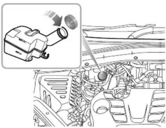
natural_image
Diagram of a car engine bay with an inset showing a projector and fan assembly (no text or labels)Note: Brakefluidwilldamagepaintedsurfaces.Soak upanyspillagewithanabsorbentclothimmediately andwashtheareawithamixtureofcarshampooand water.
BrakeFluidSpecification
Usethebrakefluidrecommendedandcertifiedby themanufacturer .Referto"RecommendedFluidsand Capacities"inthe"TechnicalData"chapter.
IMPORTANT
ReplacebrakefluidregularlyaccordingtotheService Schedule.
MAINTENANCE
Battery
BatteryMaintenance

DONOTleaveelectriccomponentsswitched onwhentheengineisnotrunning,the batterymaybecomeflatandyouwillnotbe abletostarttheengine.
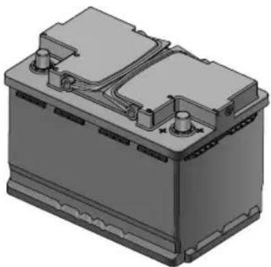
natural_image
3D rendering of a battery housing with cooling fins and mounting feet (no text or symbols visible)Y oucanseethebatterywhenyouopentheengine compartment.Thebatterysimaintenance-freetype, thereforethereisnoneedtorefillfluid.
Note: If the vehicle is stored for more than 1 month, removethenegativeterminal from the battery. Make sure that the START/STOP switch has been turned off before connecting or disconnecting then negative terminal. When connecting then negativeterminal again, the vehicle must be left in a locked state for 4 hour store-calibratethe battery condition. Failure to adher to this will inhibit the stop/start functionality.
BatteryReplacement

The battery contains sulphuric acid, which is corrosive.
Thebatterycontainssulphuricacid,whichiscorrosive. PleasegotoalocalMGAuthorisedRepairertoremove andinstallthebattery.
Note: Only fit areplacement battery of the same type and specification as the original to maintain the correct vehicle functionality.
MAINTENANCE

Thebatterymustbedisposedofusinganapproved
method, usedbatteriescanbeharmfultotheenvironment.
Itshouldberecycledbyaprofessionalcompany.Please
consultanMGAuthorisedRepairerformoredetails.
Washer
WasherFluidCheckandT opUp

Whenfillingthewasherfluid,DONOTletthe washerfluidspillonpartsaroundtheengine oronthepaintsurfaceofvehiclebody.In casethewasherfluidisspilledonhandsor otherpartsofthebody,pleaseimmediately washwithcleanwater.
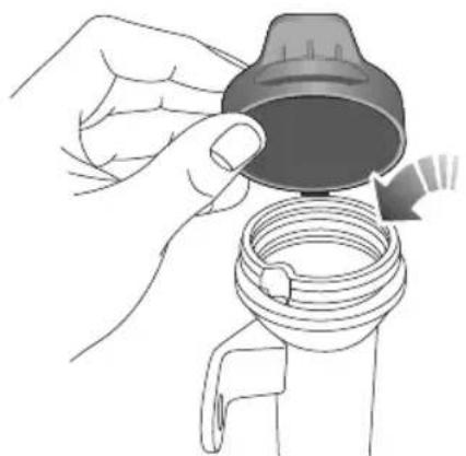
natural_image
Illustration of hands holding a valve component with a coiled spring (no text or symbols)Checkthewasherfluidleveveryweek.Whenthelevel ofwasherfluidislow,pleasetopupthewasherfluidas instructed.Pleaseusethewasherfluidrecommended and certifiedbythemanufacturer.Referto'Recommended FluidsandCapacities'in"T echnicalData"chapter.
Note: DONOTuseananti-freezeorvinegar/water solutioninthewasherreservoir-anti-freezewill
MAINTENANCE
damagepaintworkwhilevinegarwilldamagethe washerpump.
IMPORTANT
- Use the washer fluid recommended and certified by the manufacturer. Misuse of washer fluid in winter may caused damage to the washer motordueto freezing.
• Usingthewasherswitchwhenthereisnowasher fluidmaycausedamagetothewashermotor. - Operatingthewiperswhenthewindscreenisdry andthereisnowasherfluidmaycausedamageto thewindscreenandwipers.Pleasespraythewasher fluidandstartthewiperswhenthereisadequate washerfluid.
WasherNozzles
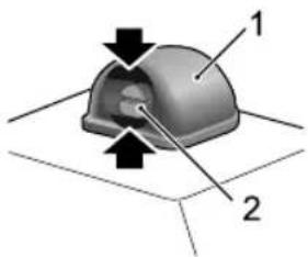
text_image
Diagram of a mechanical component with labeled parts 1 and 2, showing directional arrows indicating movement or force.Operatethewashersperiodicallytocheckthatthenozzles areclearandproperlydirected.
Thewindscreenwashernozzlesareconfiguredduringthe production.T oadjustthewindscreenwashernozzle,you caninsertasmallflat-bladedscrewdriverintheupper andbottomgaps(asindicatedbythearrow)between the housing(1)andthenozzle(2)andturndownwardor upwardslightlytoadjusttoappropriateinjectionangle.
If thenozzleisobstructed, insertaneedleorthinmetal wireintotheholetoremovetheobstruction.
Wipers
WiperBlades
| IMPORTANT |
| •Grease,siliconandpetroleumproductsimpairtheblade'swipingcapability.Cleanthewiperbladesinwarmsoap water,andchecktheirstatusperiodically. |
| •Cleanthewindscreenfrequently.DONOTusewiperstoremovestubbornoringraineddirt,itwillreducetheir effectandtheirlifespan. |
| •Ifsignsofhardnessorcrackingintherubberarefound,orifthewipersleavestreaksorunwipedareasonthescreen, thenthewiperbladesshouldbereplaced. |
| •Cleanthewindscreenregularlywithanapprovedglasscleanerandensurethewindscreenisthoroughlycleaned beforefittingreplacementwiperblades. |
| •Onlyfitreplacementwiperbladesthatareidenticaltotheoriginalspecification. |
| •Cleaniceandsnowfromthewipersandensuretheyarenotfrozenorotherwisestickingtothewindscreenbefore attemptingtooperatethem. |
MAINTENANCE
ReplacingFrontWindscreenWiperBlades
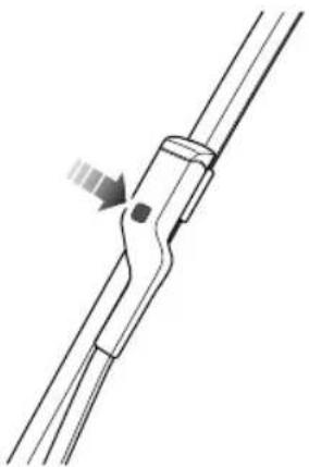
natural_image
Pure mechanical component diagram without any text, numbers, or symbolsIWiththebonnetinclosedstate,andwithin20seconds ofsettingtheSTART/STOPSwitchtotheOFFposition, operatethewiperstalkswitchbypassingdownand release,thewiperswillenterthe'serviceposition'and stoponthewindscreen.
2Liftthewiperarmawayfromthewindscreen.
3Pressthebuttononthewiperarm(asillustrated), andpulltheupperendofthewiperbladeoutwardto disengagefromthewiperarm.
4Unhookthebladefromthewiperarmanddiscard.
5Locatethenewwiperintotheslotofthewiperarm.
6Pushthewiperbladetowardsthearmuntilthewiper bladeisengaged.
7 Check whether the wiper blade is fitted correctly to the arm before positioning on the windscreen.
8Operatethewiperstalkswitchbypassingdownagain andrelease,orsettheStart/StopSwitchtoON,the wiperwillexittheservicemodeandautomatically returntoitsoriginalposition
ReplacingRearWindowWiperBlades
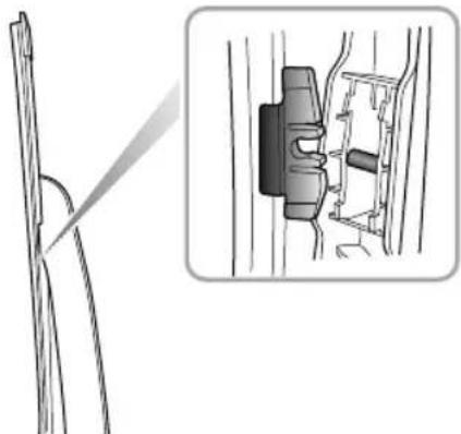
natural_image
Technical illustration of a mechanical component with cross-section view (no text or symbols)I Liftthewiperarmawayfromthewindscreen.
2Pullthewiperbladeconnectoroutwardwith moderateforcetoseparateitfromthewiperarmand discardthewiperblade.
3Putthefittingofthenewwiperbladeintotheslot ofthewiperarm.Ensurethewiperbladeisproperly securedonthewiperarm.
4Placethewiperassemblybackonthewindscreen.
MAINTENANCE
T yres
Overview
• T akeextracarewhenusingnewtyresforthefirst 300miles(500km).
- Avoidexcessivecorneringatspeed.
- Regularlychecktyresfordamageandforeignobjects -removeanyforeignobjectsfromthetread.
- Avoidtyrecontactwithoils,greaseandfuel.
- Ensurevalvecapsarealwaysfitted.
- Ifthetyreistoberemovedalwaysmarkthetyre/wheel orientationtoensurecorrectrefitment.
NewT yres
Newtyresmaynothavethesameadhesionproperties of the oldtyres, pleasetakeextracarefor300miles(500km). This action could benefittyrelife.
T yreorrimdamagecanhappenunnoticed.lfabnormal vibrationsorhandlingisexperienced,oryouthinktyreor rimdamagehasoccurredpleasecontactanMGAutorised Repairer.
DirectionalT yres
Directionaltyresaremarkedwith'directionofrotation'(DOR).T omaintainhandlingcharacteristics,tyre performance,lowroadnoiseandextendtyrelife,tyres mustalwaysbefittedwithindicationarrowshowingthe correct'DOR'.
T yreLife
Correcttyrepressuresandmoderatedrivingstylecan extendtyrelife.Itisrecommendedtonotethefollowings inservice:
- If the vehicle is restored for all lengthy time, please move your vehicle at once two weeks to rotate the tyres'.
•T yrepressures should be checked monthly when the tyres are cold.
- Avoidcorneringatexcessivespeeds.
• Regularlychecktyresforabnormalwearpatterns.
The following factors affect theetyrelife:
TyrePressures
Incorrecttyrepressurescanresultinpoordriving characteristicsandashortenedtyrelife.T yrepressures shouldbecheckedatleastonceamonth,andonceprior toeachlong-distancejourney.
DrivingStyle
Excessivelyharshaccelerationandbrakingwhilstcornering willreducetyrelife.
WheelBalance
Thebalanceofwheelsandtyresarewelltestedbeforea newvehiclecomesoutofthefactory.Butthewheelsmay beoutofbalanceduetomanyfactors.Ifwheelsareout ofbalance, shakingorvibrationofthesteeringmechanism mayoccurandthetyresmaystarttowearexcessively.It isimportanttorectifythisquickly.Eachwheelshouldbe rebalancedafterinstallinganewtyreorhavingatyrerepair.
WheelAlignment
Incorrectwheelalignmentcancauseexcessivetyrewear and affect vehiclesafety. If the tyresshowsignsofabnormal
wear, check the wheel alignment and seek advice from a MGA authorised repairer.
MAINTENANCE
T yreCheck

DEFECTIVETYRESAREDANGEROUS!
DONOTdriveifanytyreisdamaged, is excessivelyworn, orisinflatedtoanincorrect pressure.
Alwaysdrivewithconsiderationfortheconditionofthe tyres,andregularlyinspectthetreadandsidewallsforany signofdistortion(bulges),cutsorwear.
Note: If possible, protecttyres from contamination by oil, grease and fuel.
T yrePressures

Beforealongdistancejourney,thetyre pressuremustbechecked.
Checkthepressures(includingthesparewheel)atleast everymonth,whenthetyresarecold.
Ifitisnecessarytocheckthetyreswhentheyarewarm, youshouldexpectthepressurestohaveincreasedby 30 \~ 40kPa/0.3 \~ 0.4bar/4.3 \~ 5.8psInthiscircumstance,
NEVERletairoutofthetyresinordertomatchthe recommendedpressures(cold).
Valves
Keepthevalvecapsscreweddownfirmly-thypreventdirt fromenteringthevalve.Checkthevalveforleaks(listen foratell-talehissing)whenyoucheckthetyrepressure.
PuncturedT yres
Y ourvehicleisfittedwithtyreswhichmaynotleakif penetratedbyasharpobject,providedtheobjectremains inthetyre.Ifyouareawareofthisoccurring,reducespeed immediatelyanddrivewithcautionuntilthesparewheel canbefitted,orrepairsundertaken.
Note: If the wallofthetyreisdamagedordistorted, replacethetyreimmediately, donotattemptarepair.
T yreWearIndicators
Tyresfittedasoriginalequipmenthavewearindicators mouldedintothetreadpatternatseveralpointsaroundthe circumference. Whenthetreadhasworndownto 1.6mm, the indicatorswillcometothesurfaceofthetreadpattern,
producingtheeffectofacontinuousbandofrubberacross thewidthofthetyre.
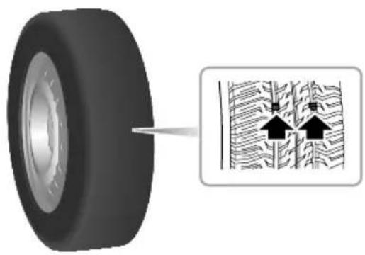
natural_image
Diagram showing a tire with an arrow pointing to a detailed cross-section of a textured surface with arrows indicating direction (no text or symbols present)IMPORTANT
Thetyremustbereplacedwhenitisworntorevealthe wearindicator,ortheremightbetheriskofaccident.
ReplacementofT yres
Itisrecommendedtoinstallthetyres consistentwiththeoriginalspecifications. DONOTreplacethetyreswithtyresofany othertype.Alternativetyres,ofadifferent specification,mayadverselyaffectthe vehicle'sdrivingcharacteristicsandsafety.In ordertomakeyourdrivingandsafetybetter guarantee,itissuggestedthatyouconsult anMGAuthorisedRepairer.
Alwayshavereplacementwheelsandtyresbalancedbefore use.
WheelFitmentRotation
It is not recommended that you swap wheels from side to side or front to rear in order to equal its setyewear. Y our vehicle is fitted with T yrePressureMonitoringSystem which means that each wheels programmed other relative position.
MAINTENANCE
If youdowishtoswapwheelsandtyresaroundonthe vehiclepleaseconsultanMGAuthorisedRepairerasextra codingwillberequired.
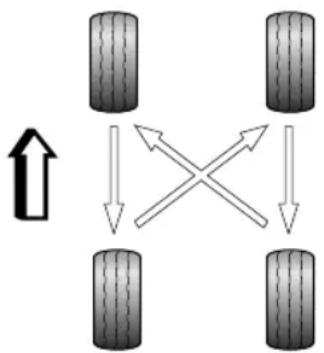
flowchart
graph TD
    A["Terr 1"] --> B["Terr 2"]
    B --> C["Terr 3"]
    C --> D["Terr 4"]
    D --> A
    style A fill:#f9f,stroke:#333
    style B fill:#f9f,stroke:#333
    style C fill:#f9f,stroke:#333
    style D fill:#f9f,stroke:#333
    note1["↑"] above A
    note2["×"] above B
    note3["↓"] above C
    note4["↓"] above D
Note: Directionaltyres(identifiedfromthearrowon thetyreside)CANNOTbeswappedfromsidetoside.
Note: TPMScoding is required after changing wheel positions, please consult local MGA authorised Repairerford details.
T yre/SnowChains
Unsuitabletyre/snowchainsmaydamagethetyres, wheels, suspension, brakesorbodyworkofyourcar.
Please pay attention to the following requirements in the usage:
- Thetyre/snowchainscanonlybefittedonthedrive wheels;
- Thethicknessoftyre/snowchainsshallnotexceed15 mm;
- Pleasealwaysobservetheinstallationandtension instructionsforthetyre/snowchains,aswellasthe speedlimitationsofdifferentroads;
- Donotdrivefasterthan50km/h;
• T oavoidthetyredamageandexcessivewearof thetyre/snowchains,thetyre/snowchainsmustbe removedwhiledrivingontheroadwithoutsnow.
SnowChainApplications
Snowchains cannot be fitted to all wheel/tyresizes.
Pleasenote: On this vehicle, snow chains can only be fitted to:
MAINTENANCE
Wheelrimsize:6.5J×17
T yresize:215/60R17
Note: If you drive on snowy and icy roads, it is recommended to use winter tyres. Consultant MG Authorised Repairer for details.
MAINTENANCE
CleaningandVehicleCare

Abuseofcareproductsmaybeharmfulto health, careproductsmustbesafelystored, especiallycan'tletchildrencontact, oritwill havethehazardofpoisoning.
ExternalCare
WashingY ourCar

Youcanonlycleanthevehiclewiththe START/STOPSwitchoff,ortheremightbe theriskofaccident.

Forvehiclecleaninginwinter,moistureor icinginthebrakingsystemwillreducethe brakingeffect,whichmayhavetheriskof accident.

DONOTuseahighpressurehosetoclean theenginecompartment-damagetothe car'selectronicsystemsmayoccur.
Inordertopreservethepaintfinishonyourcar, please observethefollowingcarepoints:
•DONOTusehotwatertowashthecar.
•DONOTusedetergentsorwashingupliquid.
• Inhotweather, DONOTwashthecarindirectsunlight.
- When using a hose, DONOT aim the water directly at window, door or sun roof seals, orthrough wheel apertures onto the brake components.
Ifthecarisparticularlydirty,useahosetoflushgrimeand gritfromthebodywork,prioritowashing.Then,washthe carusingcoldorlukewarmwatercontainingagoodquality washandwaxshampoo.Alwaysuseplentyofwaterto ensurethatgritisflushedfromthesurfaceandnotground intothepaintworAfterwashing,rinsethebodywork withcleanwateranddryoffwithachamoisleather.
Cleaningtheunderside
Note: DONOTuseahighpressurehosetocleanthe frontcompartment-damagetothecar'selectronic systemsmayoccur.
Fromtimetotime, but particularly during winter months when salthas been used on theroads, use ahosetowash the underside of the car. Flush away accumulation of mud and thoroughly clean those areas where debriscane easily collect (wheel arches and panel seams, forexample).
IMPORT ANT
- Avoidcleaningthevehicleindirectsunlight.
- Whencleaningthevehicleinwinteravoidspraying waterdirectlyontodoorlocksandpanelgapsdue toriskoficing.
- Donotuseroughspongesorclothocleanthecar, thiswilldamagethepaintworkfinish.
- Whencleaningtheheadlampsdonotuseadrycloth or sponge, useonlywarmsoapywater.
CleaningwithHighPressureCleaner
Alwaysreadthemanufacturersoperatinginstructions.
When using high pressure washers, always ensure there is adequate distance between the spray nozzle and any soft materials, decals or rubber seals.
IMPORT ANT
- Please pay attention to the operating instructions of high pressure cleaner.
- Softpartsonthevehiclesshouldbekeptinalarge enoughdistancefromthehighpressurecleaner.
BodyProtection
Afterwashing,examinethepaintworkfordamage.Ifthe damagehasrevealedbaremetal,useacoloredprimerfirst, thenapplythecorrectcolourbasecoatandfinishoffwith alacquerpencil,ifappropriate.Carryoutthistreatment afterwashingbutbeforepolishingorwaxing.More extensivedamagetopaintorbodyworkmustberepaired inaccordancewiththemanufacturer'srecommendations. FailuretodothiswillinvalidatetheAnti-Corrosion Warranty.lfindoubt,askyourMGAuthorisedRepairer.
PolishingthePaintwork

DONOTusecarpolishcontainingcoarse abrasives—thesewillremovethepaintfilm anddamagetheglossfinish.
MAINTENANCE
Polishingisonlyrequiredwhentheautomotivepainthas tarnishedandcannotreturntothebrightappearanceby waxing.
Occasionally treat the paints surface with an approved polish containing the following properties:
- Verymildabrasivestoremovesurfacecontamination withoutremovingordamagingthepaint.
- Fillingcompoundsthatwillfillscratchesandreduce theirvisibility.
- Waxtoprovideaprotectivecoatingbetweenthepaint andtheelements.
Note: If possible, avoid applying polishor wax product stowindow glass and rubber seals.
WiperBlades
Washinwarmsoapywater.DONOTusespiritorpetrol basedcleaners.
WindowsandMirrors
Regularlycleanallwindows,insideandout,usingan approvedglasscleaner.
Windscreen: In particular, clean the outside of the screen with glass clean after washing the car with wash and wax products, and before fitting new wiper blades.
Rearscreen: Cleantheinsidewithasoftcloth, usinga sidetosidemotiontoavoiddamagingtheheatingelements. DONOTscrapeoruseabrasivecleaners—thiswilldamage theheatingelements.
Rearviewmirrors: Washwithsoapywater.DONOTuse abrasivecleaningcompoundsormetalscraper.
PlasticParts
Plasticpartscanbecleanedbytheconventionalmethod ofcleaning.Whenthestainisnoteasytoremove,you caalsospecialsolvent-freplastideaningnd curingagentfortreatment,andthepaintcuringagentis notpreferablefortreatmentofplasticparts.
PaintDamage
Anypaintdamageorstonechipsshoubetreatedwith suitabpaint/lacquenaterialsimmediatelyvoid invalidatingtheAntiCorrosionWarranty.
WeatherStrips
Anyweatherstripsorrubberaperturesealshouldbe treatedwithsuitablematerials(silicagel)iftheyarecleaned usingstrongdetergents,thisshouldavoidanystickingand maintaintheservicelifeoftheseal.
Wheels

Whencleaningthewheelsanymaterialsor waterthatcontactthebrakediscdirectly mayeffectbrakingefficiency.
Inordertoensurethewheelsarekeptinoptimum conditiontheyshouldbecleanedregularly.
Only use are recommended non-acidic proprietary wheel cleaner. Always read the instructions on the product.
CleaningtheInterior
Plasticmaterials
Cleanplastic-faced materials with diluted upholstery cleaner, then wipewith adamp cloth.
Note: DONOTpolishdashboardcomponents—these shouldremainnon-reflective.
Carpetandfabrics
Cleanwithdilutedupholsterycleaner-testaconcealed areafirst.
Leather
Cleanleathertrimwithwarmwaterandanon-detergent soap.Dryandpolishtheleatherwithadry,clean,lint-free cloth.
Note: DONOTusepetrol, detergents, furniture creams or polishes as cleaning agents.
MAINTENANCE
InstrumentPack, AudioandNavigationDisplay
Cleanwithadryclothonly.DONOTusecleaningfluids orsprays.
AirbagModuleCovers

DONOTallowtheseareastobefloodedwith liquidandDONOTusepetrol,detergent, furniturecreamorpolishes.
T oprotectdamagetotheairbagSRS, the following areasshouldbecleanedsparinglywithadampclothand upholsterycleanerONL Y:
•Steeringwheelcentrepad.
• Areaofdashboardcontainingthepassengerairbag.
- Areaofroofliningwhichenclosesthesideheadimpact protectionairbags.
SeatBelts

DONOTusebleaches, dyesorcleaning solventsonseatbelts.
Extendthebelts, thenusewarmwaterandanon-detergent soaptoclean. Allowthebeltstodrynaturally; DONOT retractthemorusethecaruntiltheyarecompletelydry.
TechnicalData
334TechnicalDataDimensions
336Weights
340 MajorParametersofEngine
34 I Recommended Fluids and Capacities
342 Four-Wheel Alignment Parameter Table(Unladen)
342 WheelsandTyres
342TyrePressure(Cold)
T echnicalDataDimensions
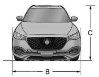
text_image
C B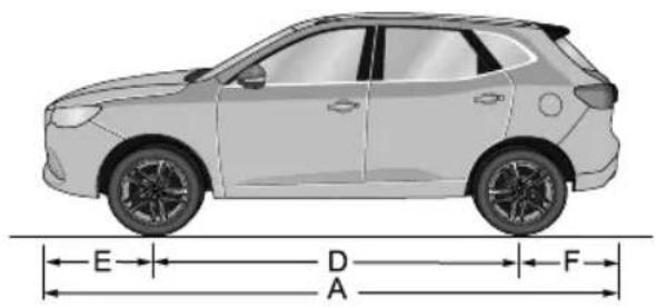
text_image
E D A F| Item,unitsParameter | |
| OveralllengthA,mm4574 | |
| OverallwidthB,mm1876 | |
| OverallheightC(unladen),mm | 1664 (withbody)1685 (includingsharkfin) |
| WheelbaseD,mm | 2720 |
| FrontOverhangE,mm963 |
TECHNICALDATA
| Item,unitsParameter | |
| RearOverhangF ,mm891 | |
| Frontwheeltrack,mm | 1574 |
| Rearwheeltrack,mm | 1593 |
| Minimumgroundclearance(laden),mm145 | |
| Minimumturningcirclediameter,m | 11.9 |
| Fueltankcapacity,I55 |
Note: Doormirrorsandthedeformedportionoftyrewalldirectlyabovethetouchdownpointarenotincluded inthetotalwidth.
TECHNICALDATA
Weights
'5 886
| Item,units | Parameter | ||||
| 1.5T -MT | 1.5T -AT | ||||
| Personincab,person5 | |||||
| Unladenvehicleweight (kerb),kg | 1463146915 | 1314891535 | |||
| Massoftheoptional equipment,kg | 26 | ||||
| Grossvehicleweight,kg20012023 | |||||
| Unladenfrontaxleweightkg | |||||
| 632Unladenfrontaxleweight,kg 609 | 607 | ||||
| Ladenfrontaxleweight,kg | |||||
| Ladenrearaxleweight,kg | 10141014 | ||||
TECHNICALDATA
T owingWeights
| Item,Units | Parameters | |
| 1.5T -MT | 1.5T -AT | |
| T owinglimitunbraked,kg | 740/745/750750/750 | |
| T owinglimitbraked,kg | 17501750 | |
| T owinghitchload,kg7575 | ||
TECHNICALDATA
T owingBarDimensions
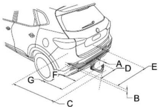
text_image
A D E G F C B| Item | DimensionDescription,UnitsParameters | |
| ABumpertocentreoftowball,mm | 77 | |
| B | Attachmentpointtocentrethetowball,mm | 55 |
| CWheelcentretocentreoftowball,mm954 | ||
| D | Centreoftowballtosidemember,mm500 | |
TECHNICALDATA
| ItemD | DimensionDescription,UnitsParameters | |
| EDistancebetweensidemembers,mm | 1000 | |
| F | Centreoftowballtocentreoffirstattachmentpoint,mm294 | |
| G | Centreoftowballtocentreofsecondattachmentpoint, mm | 508 |
TECHNICALDATA
MajorParametersofEngine
| Vehicle | Parameter |
| 1.5T | |
| Bore×Stroke,mm×mm74×86.6 | |
| Capacity,II.490 | |
| Compressionratio | 11.5:1 |
| Fueltype,RONUnleaded95RONtoEN228SPEC |
RecommendedFluidsandCapacities
| Name | Grade | Capacity | |
| 6MTDCT | |||
| Enginelubricatingoil(after-salesreplacement),L | C50W-204 | ||
| Enginecoolant,L | Glycol (OA T) | 5.8 | |
| DoubleClutchAutomaticT ransmissionfluid,L | DEXRON®DCTFluid | — | 2.45 |
| Manualtransmissionfluid,L | MTF942.2 | — | |
| Brakefluid,LDOT41.0 | |||
| Washerfluid,L | ZY -VIII | 2.5 | |
| Airconditioningrefrigerant,g | R1234yf | ||
TECHNICALDATA
Four-WheelAlignmentParameter T able(Unladen)
| ItemParameter | ||
| Front | Camberangle-14'±45' | |
| Castorangle | 4°57'±45' | |
| T oe-inangle(total toe-in) | 8'±12' | |
| Kingpininclination | 12°45'±45' | |
| Rear | Camberangle-60'±45' | |
| T oe-inangle(total toe-in) | 12'±12' | |
WheelsandT yres
| Wheelsize | 7.5J×186.5J×17 | |
| T yresize | 235/50R1897W | 215/60R1796H |
T yrePressure(Cold)
| WheelsUnladen | |
| Front | 250kPa/2.5bar/37psi |
| Rear | 210kPa/2.1bar/31psi |
Appendix
344RemovableTowBar
APPENDIX
RemovableT owBar
T owBarOperatingInstructions
Safety:
Operationofthedetachabletowbarshouldonlybe performedbyhand,neverusehandtoolstoooperatethe lockingmechanism.
If the trailer is fitted with a security cable or brakeable it must be attached to the dedicated connection hole in the fixed part of the window bar.
Whenastabilisercouplingisinstalledonthetrailernever usegreaseonthetowball.
Alwaysremovethedetachabletowballwhennotinuseif itobscurestheregistrationplate.
Preparation:
Removetowballcover.
Ensurethetowballiscleanandfreefromdirtanddebris.
Ensurethetowballisinthe'springposition'(seepicture 3.1).
Thetowballisinthespringpositionif:
•Theoperatinghandleispushedincompletelyandno colourindicationisshowninsidetheindicationareaof theoperatinghandle.
- Thesliderispulledfullytowardsthetowball(shownin picture3.1).
- Itisnotpossibletolockthesystemwiththesupplied lockingkeys(seepicture5.2).
ThetowballisNOTinthespringpositionif:
•Theoperatinghandleispoppedoutandshowsared fieldintheindicationareaoftheoperatinghandle(see picture3.1)
- Thesliderispushedouttowardsthetowball(thepart isindicatedbyinpicture3.1).
- Itispossibletolockthesystemwiththesuppliedkeys (seepicture5.2).
T oplacethetowballinthespringposition:
- Unlockthetowball(seepicture6.1)
- Pushtheoperatinghandleinwards,rotateinaclockwise direction(whilstpushinginwards)untilthehandle remainsinposition(seepicture3.2).Ifunsurerepeat operation.
Note: If atowball cannot be tensioned into the spring position it cannot and MUST NOT be used.
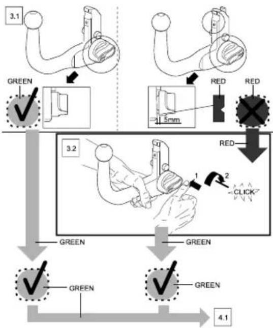
flowchart
graph TD
    A["3.1"] --> B["GREEN ✓"]
    B --> C["1.5mm"]
    C --> D["RED RED"]
    D --> E["3.2"]
    E --> F["GREEN ✓"]
    F --> G["GREEN ✓"]
    G --> H["4.1"]
    style A fill:#f9f,stroke:#333
    style H fill:#f9f,stroke:#333
Attachment:
Beforeattachingthetowballtothecarpleaseremovethe coverfromthehousing(seepicture4.1).
- Inserttowball(thatmustbeinthespringposition)fully intothehousing.
- Holdthetowballinposition,keepingyourhandsaway fromtheoperatinghandle,useaslightforcetopullat thetowballasshowninpicture4.3.
• The unlockingpinwilltriggerthelockingmechanismand thelockingprocesswillautomaticallytakeplace.
•Alwayscheckthetowballiscorrectlyinstalled, this can berecognised by:
•Theoperatinghandlepopsoutandaapproximategap of5millimeterswillbevisiblebetweenthetowballand theoperatinghandle(seepicture5.1). - Agreenfieldwillbevisibleintheindicationareaofthe operatinghandle(seepicture5.1).
- Thetowballcanbelockedusingthesuppliedkeys(see picture5.2). Thiscanonlybedonewhenthehandle haspoppedoutcompletely,afterthisthehandlecanno longerbepushedinandthetowballcannotbereleased (remembertoremovethekeys).
APPENDIX
- Checkthetowballforsecurity-noplayshouldbe evident.
Thetowballisnowreadyforuse.
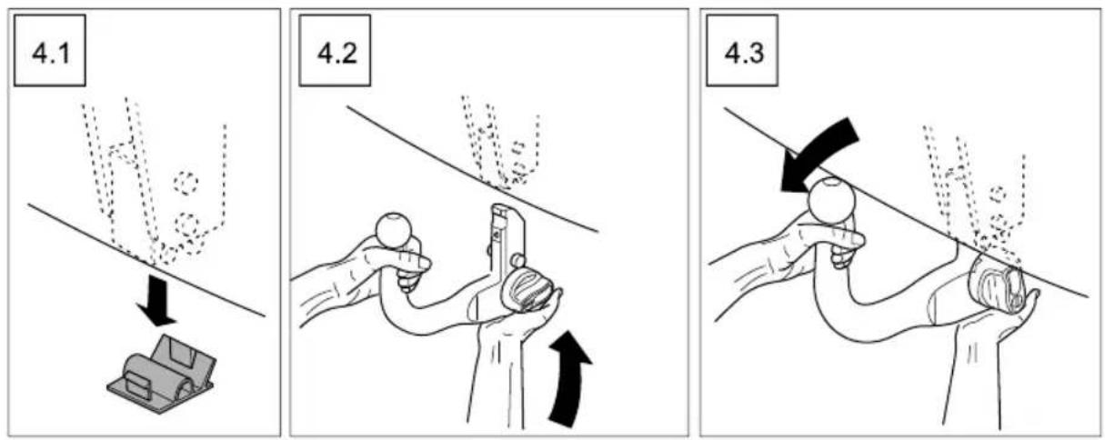
CarePoints
•Alwayscheckthetowballforcorrectmountingevery timepriortouse.
- Neverattempttoattach/detachatowballwhilst trailer/accessoryattached.
•Alwayskeepthetowballcleanandfreefromdebris,do notcleanwithhighpressurewasher.
- Neveruseatowballthatassignsofdamage,excessive wearormodification.
- Neveruseatowballthathasbeeninstalledbyanyother methodthan'handpressure'.
Removal
Always disconnect the trailer/accessory and safetyable prioritotow ball removal.
- Unlockthedetachabletowballbyturningthelocking keyclockwiseusingyourthumbandforefinger(see picture6.1).
-
Holdthetowballwithyourlefthand,pushthe operatinghandlefullyinwardsandturnclockwiseuntil theoperatinghandleremainsinposition(seepicture 6.3).
-
Thetowballcannowberemovedfromthehousingin adownwardmotion(seepicture6.4).WARNING,this itemisheavy,donotallowittodrop.
• Refittheplasticcoverintothehousing(seepicture6.5).
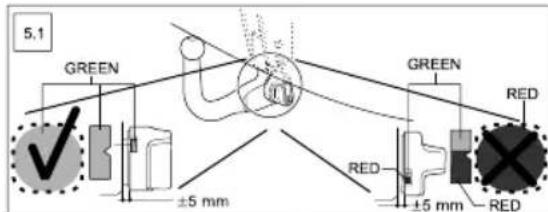
text_image
5.1 GREEN ±5 mm GREEN RED RED ±5 mm RED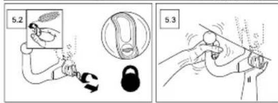
text_image
5.2 5.3APPENDIX
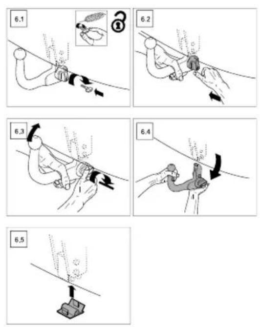
ADDENDUM – AIR CONDITIONING AND AUDIO SYSTEMS
Restricted Operation During Apple CarPlay and Android Auto Telephone Calls
Whilst the Infotainment System is connected to a mobile telephone via Apple CarPlay or Android Auto, certain telephone functions may restrict the display change function.
During a telephone call using Apple CarPlay or Android Auto the Infotainment System screen displays details of the call and caller/contact. This screen cannot be changed or exited during the call and therefore restricts access to other functions that are available via the Infotainment System screen.
Air Conditioning and Heater (HVAC) Function Restrictions
During an Apple CarPlay or Android Auto telephone call it is not possible to access the HVAC adjustment function within the Infotainment System. This means that blower speed and temperature settings cannot be accessed or adjusted.
To switch the AC blower on or off during a telephone conversation whilst using Apple CarPlay or Android Auto please hold the AC Control Shortcut key in the Control Panel for 3 seconds, the blower will switch on or off depending on the current working state.
Note: When switching the blower back on, the speed settings will revert to the settings prior to switching off.
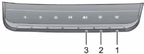
text_image
3 2 1I Defrost/Demist Button
2 Heated Rear Window Button
3 A/C Control Shortcut