ZS EV (2019) - Automotive MG - Free user manual and instructions
Find the device manual for free ZS EV (2019) MG in PDF.


User questions about ZS EV (2019) MG
0 question about this device. Answer the ones you know or ask your own.
Ask a new question about this device
Download the instructions for your Automotive in PDF format for free! Find your manual ZS EV (2019) - MG and take your electronic device back in hand. On this page are published all the documents necessary for the use of your device. ZS EV (2019) by MG.
USER MANUAL ZS EV (2019) MG
Warranty and Service....I
SymbolsUsed....2
ImarEmergency....3
VehicldentificationInformation....4
Vehicle identification....4
VehicleIdentificationLabel....5
Instructions for Use to Electric Vehicle....7
Effects Ambient Temperature....7
Instructions for High Voltage Battery Pack Recycling....7
DrivingRange....8
EqualisationCharging....9
IntelligenCharging....9
CrashOutageControl....10
High Voltage System....10
Precautions the Event of Accident....12
CONTENTS
l InstrumentsandControls....13
Instruments and Controls....14
InstrumenPack....16
InformationCentre....18
Warning lights and indicators....28
LightandSwitches....40
MasterLighting switch....40
Headlamp Levelling Manual Adjustment 42
MainBeamSwitch....43
DirectionIndicatoSwitch....46
FogampSwitch....46
Hazard Warningamp....47
WipersandWashers....48
WindscreenWiperOperation....48
RealWindowWiperOperation....50
SteeringSystem....52
AdjustmentSteeringColumn....52
Electric Power Steering....52
CONTENTS
Horn....54
RearviewMirrors....55
ExteriorDooMirrors....55
ManuaAnti-dazzInteriorRearviewMirror....57
Sunvisor....58
Windows....59
WindowOperation....59
Sunroof * 62
Instructions....62
SunrooOperation....63
InteriorLight....68
PowerSocket....69
FrontPowerSocket....69
RealUSBPorts....70
TopUSBPort....70
WirelessChargingSystemforMobilePhones * 72
WirelessChargingMobilePhones....72
StorageDevices....74
CONTENTS
Instructions....74
GlovoBox....74
CentreConsoleArmresBox....75
Loadspace....75
CupHolder....77
CentreConsole Cup Holder....77
RoofLuggageRack * 78
MaximumAuthorised Loadorthe Roof....78
PeriodicaCheck....78
2AirConditioningandAudioSystems....79
Ventilation....80
A/Filter....81
Vents....81
A/CControPanel....83
ControPanel....83
A/CControShortcut....83
Defrost/Demist....83
HeatedRealWindow....84
CONTENTS
BloweSpeedControButton....84
TemperatureControButton....84
A/CControInterface....85
ControllInterface-ConnectedCar * 85
ControllInterface-NonConnectedCar * 86
TemperatureControl....87
CoolingOn/Off....87
AutoMode....87
SystemOn/Off....87
BloweSpeedControl....87
AiDistributionMode....87
AiCirculationMode....88
InfotainmentSystem \* 90
Important Safety Information....90
PrivacyandDatSharing....91
CautionsoUsingscreen....91
Basic Operations....92
Bluetooth|Phone....97
Entertainment....100
CONTENTS
Vehicle-Mobile Phoninterconnection....106
EnergyManagement....107
MGT ouchpoint....107
VehicleSetting....107
Setting....108
3Seats&Restraints....III
Seats....112
Overview....112
HeadRestraints....112
FronSeats....113
Reaßeats....115
FrontSeatHeating 116
SeaBelts....117
Protection Provided by Sea Belts....117
Wearing Sea Belts....119
Children and Sea Belts....123
SeaBelPre-tensioners....124
SeaBelChecksMaintenanceandReplacement....125
AirbagSupplementaryRestraintSystem....128
CONTENTS
Overview....128
AirbagDeployment....129
Conditions in Which Airbag Will No Deploy....132
DisablingthePassengerAirbag....133
ServicandReplacementAirbags....135
DisposabAirbags....136
ChildRestraints....137
Important Safety Instructions about Using Child Restraints....137
ChildRestraintGroups....140
ApprovedChildRestrainPositions....142
Starting&Driving....147
Keys....148
Overview....148
ReplacingBattery....149
ChildProoLocks....151
AlarmSystem....152
PowerImmobilisation....152
BodyAnti-theffsystem....153
CONTENTS
Tailgate....158
StartingandStoppingthePowerSystem....160
STARTSTOP switch....160
READ Mode....161
SwitchingthePowerSystemOFF....163
PedestrianAlerControSystem....164
EconomicalandEnvironmentalDriving....165
Running-in....165
Economic Driving....165
DrivingSpecialEnvironment....166
CheclanService....167
ChargingandDischargingRequirements....168
Charging You Vehicle Home....170
InstalledChargingPoints....170
HomeChargingGuide....170
Charging and Medical Condition Awareness....171
ChargingPort....171
ElectricChargingIdentifierLabel * 173
RapidCharging....175
CONTENTS
SlowCharging....176
ChargingInformation....179
EqualisationCharging....180
ChargingTimes....180
Discharging....184
ElectricDriveTransmission....186
Instructions....186
GeaShiftControl....186
Driving Hills....189
DrivingMode....189
EnergyRegeneration....191
EnergyManagement....192
ProtectionMode....193
BrakeSystem....195
ElectronicBrakeForceDistribution(EBD)....195
ElectroniBrakeAssistance(EBA)....196
Anti-locIBrakSystem(ABS)....196
HillHoldContro(HHC)....197
HilDescenContro(HDC)....198
CONTENTS
AutoHold....199
ActiveRolloveProtection(ARP)....201
Emergency Braking Hazard Warning light Control(HAZ)....201
Multi-CollisionBrakSystem(MCB)....202
StabilityControSystemandTractionControSystem....203
Electronic Parking Brake(EPB)....204
AdaptiveCruiseControSystem....206
Adaptive Cruise Control System Activation....206
Adaptive Cruise Target Speed Adjustment....209
Adaptive Cruise Target Following Distance Adjustment....209
Adaptive Cruise Pause/Standby....210
AutomaticDeactivationAdaptiveCruise....210
Adaptive Cruise Override....210
Adaptive Cruise Resume....211
CleaSpeedMemory....211
Adaptive Cruise Control System Impairment and Effectiveness....211
SpeciaDrivingEnvironments....211
ParkingAidSystem....215
UltrasoniSensorParkingAid....215
CONTENTS
360AroundViewSystem....217
RearDriverAssistanceSystem \* 218
SystemOverview....218
SwitchingtheSystemFunctionOn/Off....220
SystemFunctions....220
T yrePressureMonitoringSystem(TPMS)......224
DrivingAssisSystem....225
DescriptionFrontViewCamera....225
DescriptionFromDetectionRadar....226
SpeedAssisSystem....227
LaneAssisSystem....232
TraffigamAssisSystem....235
ForwardCollisionSystem....238
LoadCarrying....242
Loadspace Loading....242
InternalLoading....242
GeneralT owing Safety....243
5EmergencyInformation....245
CONTENTS
HazardWarningDevices....246
Warning Triangle....246
eCalSOEmergencyAssistance....247
EmergencyStarting....250
VehicleRecovery....252
Towing for Recovery....252
TransporterTrailer....255
TyreRepair....256
Toolidentification....257
TyrRepair....257
ChangingaWheel ^* 260
FuseReplacement....264
Fuse....264
FusBox....264
PassengerCompartmenFuseBox....265
FronCompartmenFusBox....268
BullReplacement....271
BullSpecification....271
BuiltReplacement....272
CONTENTS
&Maintenance....279
Maintenance....280
RoutineServicing....280
Bonnet....283
Opening Bonnet 283
ClosinghBonnet 283
BonneOpenWarning....283
FronCompartment....285
CoolingSystem....286
CoolanCheelandTopUp....286
Coolan&pecification....286
Brake....288
Brakøpads....288
BrakeFluidCheckandTopUp....288
Brake Fluid Specification....289
Battery....290
BatteryMaintenance....290
Battery Replacement....291
CONTENTS
HighVoltageBatteryPack....292
Precautions and restricted condition for use battery....292
Washer....294
WasherFluidCheclandTopUp....294
Washet Nozzles....295
Wipers....296
WipeBlades....296
ReplacingFrontWipeBlades....297
Replacing Real Wipe Blades....298
Tyre....299
Overview....299
Caring for your T yres....300
TyreWeaIndicators....301
TyrRotation....302
Tyre/SnowChains....304
CleaningandVehicleCare....305
Exterior....305
CleaningInterior 308
CONTENTS
echnicaData....311
TechnicaDataDimensions....312
Weights....314
TowingWeights....315
Towing Bar Dimensions....316
ParametersoffractionMotor....318
RecommendedFluidsandCapacities....319
WheelAlignment(UnladenCondition)....320
WheelsandT yres....320
TyrePressure(Cold) 320
8Appendix....321
RemovableTowBar....322
TovBarOperatingInstructions....322
Introduction
TheOwner'sHandbook
This handbook describes all of the vehicles and standard equipments specification within the model range. Some of the information therefore, may not apply to your particular car.
Alwaysrememberthatifyouhaveanyqueriesconcerning theoperationorspecificationofyourcar,yourMG AuthorisedRepairerwillbegladtoadviseyou.
The illustrations in the Owner's Handbook are for reference only.
The information presented in this manual may vary slightly depending on vehicle configuration, software version and sales area.
StatusatTimeofPrinting
MGoperatesapolicyofconstantproductimprovement andthereforereservestherighttochangespecifications withoutnoticeatanytime.Whilsteveryeffortis madetoensurecompleteaccuracyoftheinformation inthispublication,noliabilitiesforinaccuraciesorthe
consequencesthereof,includinglossordamageto property,orinjurytopersons,canbeacceptedbythe manufacturerorMGAuthorisedRepairerwhosupplied thepublication,exceptinrespectofpersonalinjurycaused bythenegligenceofthemanufacturerorMGAuthorised Repairer.
WarrantyandService
Pleaseconsulttheownerssectionatwww.mg.co.ukforthewarrantytermsandconditions,warrantystatement,exemptionsandserviceitemrenewalschedule.
PREFACE
SymbolsUsed
The following symbols used within the handbook can your attention to specific types of information.
Warning

This warningsymbolidentifies procedures that must be followed precisely, or information that must be considered with great care, inordertoreducetherisk of personal injury or serious damage to the car.
Important
IMPORTANT
Thestatementsstatedheremustbefollowedstrictly, otherwiseyourcarcouldbedamaged.
Note
Note: This describes helpful information.

Thissymbolindicatesthatpartsdescribedmustbe dofbyauthorisedpersonsorbodiestoprotectthe ment.
Asterisk
Anasterisk(*)appearingwithinthetext,identifiesfeatures oritemsofequipmentthatareeitheroptional,orareonly fittedtosomevehiclesinthemodelrange.
IllustrationInformation

Identifiescomponentsbeingexplained.

Identifies movement of components being explained.
InanEmergency
IMPORTANT
Rememberthebreakdownsafetycode
Ifabreakdownoccurswhiletravelling:
- Whereverpossible,consistentwithroadsafetyand trafficconditions,thecarshouldbemovedoffthe mainthoroughfare,preferablyintoalay-by.lfa breakdownoccursonamotorway,pullwelloverto theinsideofthehardshoulder.
- Switchonhazardlights.
•Ifavailable,positionawarningtriangleoraflashing amberlight50to150metres(150to500ft)behind yourvehicletowarnapproachingtraffic.Noteitisa legalrequirementofsomecountriesthatawarning triangleiscarriedinthevehicle,ifindoubtconsult thelocalhighwaysagencyforfurtherinformation. - Considerevacuatingpassengersthroughnearside doorsontothevergetoreduceriskofinjuryinthe eventofcollision.
PREFACE
VehicleIdentificationInformation
VehicleIdentification
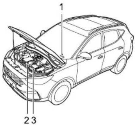
text_image
1 2 3I VehicleIdentificationNumber(VIN)
2DriveMotorNumber
3ElectricDriveSystemNumber
AlwaysquotetheVehicleIdentificationNumber(VIN) when communicating with MGAuthorised Repairer. If the drivemotororelectric drivesystem is involved, it maybe
requiredtoprovidetheidentificationnumbersofthese assemblies.
VehicleIdentificationLocation
VehicleIdentificationNumber(VIN)
•Onthefloorunderthefrontdriverseat;
• Ontheidentificationplate;
- Stampedonaplatevisiblethroughthebottomlefthand cornerofthewindscreen;
- Ontheinnersideofthetailgatevisiblebyopeningthe tailgate.
Note: The DLC is located in the driver footwell at the base of the fasci panel on the RH side. The VIN information can be extracted from the vehicle using the approved diagnostic equipment.
DriveMotorNumber
Stampedonthelowerpartofthedrivemotorhousing.
ElectricDriveSystemNumber
Stampedbehindtheupperpartoftheelectricdrivesystem housing.
VehicleIdentificationLabel
The vehicle identification label contains the following information:
•T ypeApprovalNumber;
•VehicleIdentificationNumber(VIN);
•GrossV ehipcleWeight;
•GrossT rainWeight;
•MaxFrontAxleWeight;
•MaxRearAxleWeight;
- PaintCode;
•T rimCode;
PREFACE
LocationofVehicleIdentificationLabel
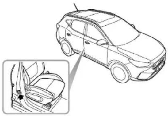
The identification label is located at the lowersideofright pillarB.
natural_image
Line drawing of a car showing front and side views, with an inset close-up highlighting the interior portion (no text or symbols)InstructionsforUseofElectricVehicle
EffectsofAmbientT emperature
The working performance of the high-voltage battery pack fitted to your vehicle is related to the ambient temperature. This battery power the vehicle power system and therefore it is recommended that where possible the vehicles should be used within the temperature range of 15 to 45°C. This will ensure that the vehicle is in the optimum working state, and help extend the service life of the high-voltage battery pack. Extremely higher low temperatures will affect the performance of the high-voltage battery pack and vehicle.
InstructionsforHighVoltageBatteryPack Recycling
The high-voltage battery pack fitted to your vehicle contains several battery cells. installed centrally to the motor-vehicle chassis. Arbitrary disposals may cause pollution, hazard and damage to the environment. The high-voltage battery pack MUST be recycled by an MGA authorised repairer or a professional
approveddismantlingagent.Pleaserefertothefollowing informationandrequirements.
ONLYqualifiedpersonnelshouldworkwiththehigh voltagesystemtherisdangerofDEA TH.
Highvoltagesafety:thehighvoltagesystemfittedto yourvehiclefeaturesaHVbatterycontaininghigh voltagecomponentssuchaslithiumbatterypacks andhighvoltagewiringharness;DONOTattempt todismantleanyareaofthissystem,suitablytrained professionalshipubservesulationafety protectionbeforeworkingonornearthehighvoltage system.
Transportation high-voltage attack classed as a Category 9 hazardous material and must betransported by vehicles qualified in transporting Category 9 hazardous materials.
Storage: AllHVcomponents(includingbatteries) shouldbestoredatroomtemperatureandinadry environment. Theymustbekeptawayfromdangerous sources, suchasflammableobjects,heatandwater sources.
PREFACE
- Internal composition: The high-voltage battery pack consists of lithium batteries (pack), PCB, HV and normal electric wiring, metal casing and other components. It is strongly recommended that the used high-voltage battery pack generated from vehicle scrappage or any other reasons should be disposed of by an MGA authorised Repairer.
Note: If you decide not to set there recommended MG Authorised Repair to dispose of your high voltage battery, the responsibility of the consequences of environmental pollution or accidents must be bourne by the owner.
DrivingRange
The driving range of your vehicle depends on the HV battery condition, quantity of available electricity, vehicle age (current remaining battery life), weather, temperature, road conditions and driving habit etc.
Therangecanbeaffectedbyotherelectricalloads(suchas A/C, lightsetc), drivingstyleandgeneralroadconditions.
Itshouldbenotedthat:
- Thedrivingrangeisrelatedtotherateofdischarge. In ordertoavoidahighrateofdischargefromaffecting theperformanceofthehigh-voltagebatterypack, it is recommended that the vehicle is connected to asuitable charger upon illumination of the low battery warning lamp in the instrument pack.
• The actual driving range of the vehicle will reduce with the increase of vehicle age.
•TheuseofA/Cwillreducethedrivingrange.
• Thedrivingrangevariesatdifferentspeeds.
- Atlowtemperatures, the driving rangewill bereduced duetotemperature characteristics of the battery during use.
somistance:trentemperatureand lowbatteryvoltage,youmayexperienceinsufficient accelerationorpowerreduction. Thisisduetobattery characteristics.
To help increase the range of the vehicle please observe the following:
Have vehicle regularly maintained per service schedule.
•Alwaysensurethetyrepressuresarecorrect.
•T ryandusethevehiclebetweentherecommended ambienttemperatures.
- Donotparkorstorethevehicleforlongperiodswith alowstateofcharge,wherepossiblechargethevehicle as soonaspossiblepriortostorage.
- Removeunnecessaryarticlestoreducethevehicleload.
- UseofhighpowerconsumingsystemssuchasA/C andheatingwilluselargeamountsofpower.Thiswill reducethedrivingrange.
- Atahighspeed, where possible, closetehindowsto reduce wind resistance and power consumption.
- T rytomaintainasteadyspeedatalltimes, avoid constantaccelerationandbraking.
- Duringacceleration,applytheacceleratorpedalas gentlyaspossible.
- During deceleration, releasethe accelerator pedal; under certain conditions when not applying the brake orgently applying the brake, the energy regeneration system (KERS) will assist in charging the HV battery and extend the driving range.
EqualisationCharging
Inordertoassistinextendingtheservicelifeofthehigh voltagebatterypackitisrecommendedthatanequalisation chargeiscarriedoutatregularintervals.
Pleasesee"EqualisationCharging"inthe"Starting&Driving"section.
IntelligentCharging
The 12VbatterySOCisconstantlymonitored,whenthe Start/StopswitchisintheOFFpositionitispossible,under certainconditions,thattheHVbatterywillautomatically chargethe12Vbatterytoensurethevehiclestarts.This functionwillactivateandswitchoffautomatically.
Note: Thesystemwillsuspendintelligentchargingifa faultispresent, whenstartingorthevehicleisbeing chargedbyanexternaldevice.
Notdrivingngelleduceafter intelligentcharging.
Note: The intelligent charging function is suspended when the high voltage battery is in low SOC.
PREFACE
CrashOutageControl
Ifacrashorseriousimpactoccurs,asignalfromtheSDM (AirbagControlModule)willdisconnecttherelayswithin thebatterymanagementsystemisolatingthehighvoltage batteryfromthesystemsonthevehicle.
HighVoltageSystem

•Thehighvoltagesystemusedonyour vehiclefeaturesACandDCvoltages uptoabout438V.Allhighvoltage componentshavewarninglabelsattached -pleaseobservethesewarningsandany requirementswhenoperatingwithinor closetotheseareas.
•ONLYqualifiedpersonnelshouldworkon, orwith,thehighvoltagesystem-thereis dangerofDEATH.
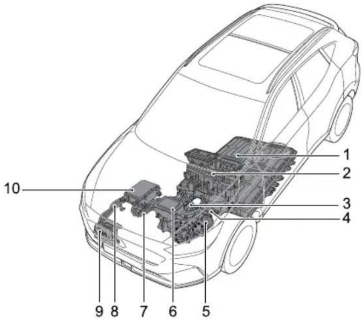
The highvoltagesystemcomponentlayoutis shown below:
text_image
1 2 3 4 5 6 7 8 9 10I HighVoltageBattery(ESS)
2ElectricHeater
3ElectricDriveT transmission
4ManualServiceDisconnect(MSD)
5ElectricA/CCompressor
6PowerDistributionUnit(PDU)
7HVBatteryHeater
8HighVoltageHarness
9ChargingPort
10CombinedChargingUnit(CCU)
PREFACE
PrecautionsintheEventofanAccident

- EnsurethevehicleisinP , theparkingbrakeisappliedandthevehiclepowersystemisOFF .
•Ifanycablesonthevehicleareexposed,inordertopreventelectricshockorevendeathDONOT makeanycontactwithanycable.
•Ifthevehiclecatchesfire,andthefireissmallandslow,acarbondioxideextinguishercanbeusedto extinguishthefire,andcontactthefireservicesassoonaspossible;ifthefireislargeandspreading quickly,immediatelyevacuatethevehicleandcontactthefireservicesimmediately.
•Ifthevehicleisinvolvedinacollisionandcannotbere-started,thenegativecableof12Vbatteryand ManualServiceDisconnect(MSD)MUSTbedisconnectedpriortorescue. - Whenthevehicleiscompletelyorpartiallyimmersedinwater,switchoffthevehiclepowersystem andevacuatethecarimmediately. Thenegativecableof12VbatteryandManualServiceDisconnect (MSD)MUSTbedisconnectedpriortorescueorassoonasthevehicleisrefloated/removedfromthe water. Observethewater/vehicleforanyabnormalsignssuchasexcessivebubblesornoises, thismay indicatebatteryshortcircuitissues.lfnosignsareevident,thereshouldnotbeashockriskfromthe bodyworkandrecoverycancommence.
- If your car is being recovered by an independent recovery agent, please contact an MGA authorised Repairer forguidance.
•Thevehicleissuppliedwithanemergencyresponseinformationcard.Pleaseshowthecardtotherescuepersonnelwhentheyarrive.
InstrumentsandControls
I 4InstrumentsandControls
16 InstrumentPack
18InformationCentre
28WarningLightsandIndicators
40LightsandSwitches
48 WipersandWashers
52SteeringSystem
54Horn
55 RearviewMirrors
58Sunvisor
59Windows
62Sunroof *
68 InteriorLight
69 PowerSocket
72 WirelessChargingSystemforMobile Phones*
74StorageDevices
77CupHolder
78 RoofLuggageRack *
INSTRUMENTSANDCONTROLS
InstrumentsandControls
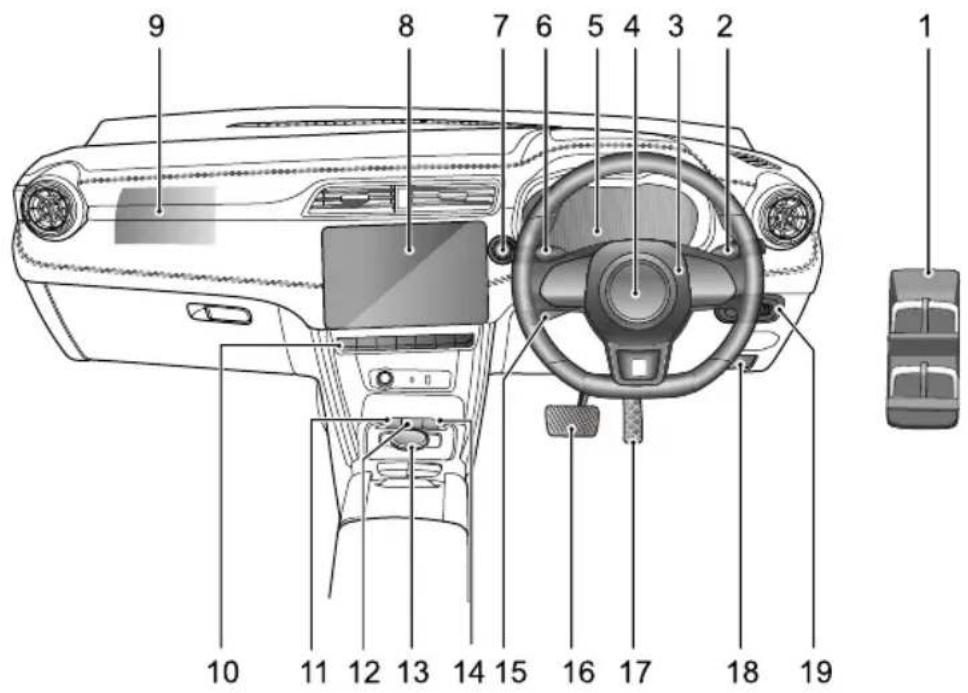
text_image
9 8 7 6 5 4 3 2 1 10 11 12 13 14 15 16 17 18 19INSTRUMENTSANDCONTROLS
IPowerWindowSwitch
2WiperStalkSwitch
3HornButton
4DriverAirbag
5InstrumentPack
6Indicator/MainBeamStalkSwitch
7START/STOPSwitch
8InfotainmentSystem
9FrontPassengerAirbag
10AirConditioning/InfotainmentControlSwitch
IIDrivingModeSelectionSwitch
I2EnergyRegenerationModeSelectionSwitch
I3ShiftControlKnob
14BatteryPowerDisplaySwitch
15 CruiseControlStalkSwitch
16BrakePedal
17AcceleratorPedal
18BonnetReleaseHandle
19 Exterior Rearview Mirror and Headlamp Leveling Switch
INSTRUMENTSANDCONTROLS
InstrumentPack

text_image
1 2 3 4 mph Motor Speed 0.0 Voltage 167 Current 167 Speed 8 7 6 5 00 100 00:00 0.0 Long Pulse Long Pulse Long Pulse Lift/Max Lift/Max Ready G: 164s 25ISpeedometer
2Warningampandindicators
3InformationCentre
4PowerMeter
Indicates the power status of the power drive system as percentage of the power is displayed positive
value represents that power system outputs power to drive the vehicle if the power is displayed as negative value represents that power system converts and kinet energy into electrical energy.
ElectricityMeterHigh-VoltageBatteryPack
INSTRUMENTSANDCONTROLS
IMPORTANT
- Whenthehighvoltagebatterypowerindicator displaysalowchargeconditionconnecttoa chargerandchargeimmediately.
•Beforeundertakinganyjourneyspleaseensure thehighvoltagebatterycontainsenoughpower.
6T otalMileage
7GearDisplay
8RangeT oEmpty
INSTRUMENTSANDCONTROLS
InformationCentre
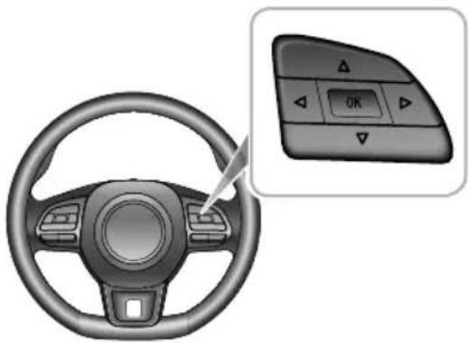
WiththevehiclepowersystemintheON/READYposition, theinformationcentrefunctioncanbeselectedasfollows:
natural_image
Interior view of a car steering wheel with a control panel showing OK button (no text or symbols on the dashboard)- PresstheUP/DOWN/LEFT/RIGHTbuttonintheRH steeringwheelmultifunctionswitchpack,thiswill accessanddisplaytheinformationcentreoptions.
- PresstheUP/DOWNbuttonintheRHsteeringwheel multifunctionswitchpacktocyclethroughoptions.
- PresstheOKbuttonintheRHsteeringwheel multifunctionswitchpacktoconfirmorlongpressthe OKbuttontoreset.
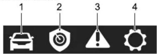
text_image
1 2 3 4IVehicleInformation
2MGPilot
3HealthCentre
4Settings
VehicleInformation
VehicleInformationincludes:
- EnergyFlow:Displaysagraphicshowingthecurrent stateofpowerflow.
• Electrical Information: Display the current operation state of the vehicle, including the voltage, current and motorspeed.
INSTRUMENTSANDCONTROLS
- CurrentJourney: Displaysthetripmileage, triptime, averagespeed and average power consumption since vehicle start. It can be reset by long pressing the "OK" button in the RH steering wheel multifunction switch pack.
- Accumulated Total:Displaysthetripmileage, triptime, averagespeed and average power consumption since the last vehiclereset. It can be reset by long pressing the "OK" button in the RH steering wheel multifunction switchpack.
MGPilot
Displaystheactivesafetyinformationofthevehicle.
HealthCentre
•T yrePressure:displaysthecurrentstatusofeachwheel.
- BatteryVoltage:displaysthe12VBatteryVoltage.
- WarningInformation: displaythewarning informationimportantoteshaurecurrently relevanttothevehicle.
Settings
LuminanceLevel
Displaysthecurrentlevelandallowsadjustmentofthe backlightbrightness.
OverSpeedThreshold
Allowsthesettingoftheover-speedalarmthreshold, pleasenote,theover-speedalarmfunctionisturnedoff when"OFF"isdisplayed.
WarningMessage
Warning messages prompt display the information of the strume park. communications are displayed in 'popup' messages, these can be divided into the following categories:
- OperatingInstruction
•SystemStateInstruction
•SystemMalfunctionAlert
Please follow the instructions displayed in the 'popup' message or in the case of awarning message, pleaserefer to therelevant section of the owners manual to follow the correct instructions.
The following are a selection of warning message that may appear in the information centre.
INSTRUMENTSANDCONTROLS
| WarningMessageProcedure | |
| DANGER!Evacuate VehicleSafely! | Assoonasconditionspermit, safelystopthevehicleand evacuateallocatecupants immediately,andcontactan MGAuthorisedRepairer immediately. |
| VehicleControl SystemFaultPlease askServingStation forHelp! | Indicatesthatthepowersystem hasdetectedafault.Please contactanMGAuthorised Repairerassoonaspossible. |
| VehicleControl SystemFaultPlease drivecarefully! | Indicatesthatthepowersystem hasdetectedafault.Pleasedrive carefullyandcontactanMG AuthorisedRepairerassoonas possible. |
| WarningMessageProcedure | |
| VehicleControl SystemFaultPlease StopSafely! | Indicatesthatthepowersystem hasdetectedafault.Assoon asconditionspermit,safely stopthevehicleandswitch thevehiclepowersystemto theOFFpositionandcontact anMGAuthorisedRepairer immediately. |
| MSAFault | IndicatesthattheManualSpeed Assist(MSA)functionhasfailed.PleasecontactanMGAuthorised Repairerassoonaspossible. |
| ISAFault | Indicatesthatthelntelligent SpeedAssist(ISA)functionhas failed.PleasecontactanMG AuthorisedRepairerassoonas possible. |
INSTRUMENTSANDCONTROLS
| WarningMessageProcedure | |
| LaneDepartureWarningSystemFault | Indicatesthatthelanedeparture warningsystem(LDW)has detectedafault.Pleasecontact anMGAuthorisedRepaireras soonaspossible. |
| EmergencyLane KeepingSystemFault | Indicatesthattheemergency lanekeepingsystem(ELK)has detectedafault.Pleasecontact anMGAuthorisedRepaireras soonaspossible. |
| ForwardCollision SystemFault | Indicatesthattheforward collisionwarningsystem(FCW)hasdetectedafault.Please contactanMGAuthorised Repairerassoonaspossible. |
| AutoEmergency BrakingSystemFault | Indicatesthattheauto emergencybrakingsystem(AEB)hasdetectedafault.Please contactanMGAuthorised Repairerassoonaspossible. |
| WarningMessageProcedure | |
| PedestrianAuto EmergencyBraking Fault | Indicatesthattheauto emergencybrakingsystem forpedestrians(AEBP)has detectedafault.Pleasecontact anMGAuthorisedRepaireras soonaspossible. |
| ACCSystemFault | Indicatesthattheadaptive cruisecontrolsystem(ACC)has detectedafault.Pleasecontact anMGAuthorisedRepaireras soonaspossible. |
| T rafficJamAssist SystemFault | Indicatesthatthetrafficjam assistsystem(TJA)hasdetectedafault.PleasecontactanMG AuthorisedRepairerassoonas possible. |
INSTRUMENTSANDCONTROLS
| WarningMessageProcedure | |
| RearDriveAssist SystemFault | Indicatesthatthereardrive assistsystem(RDA)hasdetectedafault.PleasecontactanMG AuthorisedRepairerassoonas possible. |
| PassiveEntryFault | Indicatesthatthepassivekeylessentryfunctionhasdetectedafault.PleasecontactanMG AuthorisedRepairerassoonas possible. |
| IgnitionSystem Fault | Indicatesthatthepowermodehasdetectedafault.Please contactanMGAuthorised Repairerimmediately. |
| StartStopButton Fault | IndicatesthattheSTART/STOP Switchhasdetectedafault.PleasecontactanMGAuthorised Repairerimmediately. |
| WarningMessageProcedure | |
| ABSFault | Indicatesthattheanti-lockbrake system(ABS)hasdetectedafault.andtheABSfunctionis abouttobedisabled.Please contactanMGAuthorised Repairerimmediately. |
| BrakeFault | Indicatesthatafaulthasbeen detectedwithinthebraking system.Stopthevehicleas soonassafetypermits,switch thevehiclepowersystemOFF , andcontactanMGAuthorised Repairerimmediately. |
| StabilityControl Fault | IndicatesthattheSCSsystemhas detectedafault.Pleasecontact anMGAuthorisedRepairer immediately. |
INSTRUMENTSANDCONTROLS
| WarningMessageProcedure | |
| T ractionControl Fault | IndicatesthattheTCSsystemhasdetectedafault.PleasecontactanMGAuthorisedRepairerimmediately. |
| ParkingSystem Fault | IndicatesthattheEPBsystemhasdetectedafault.PleasecontactanMGAuthorisedRepaireras soonaspossible. |
| ParkBrakeForce NotEnough | Indicatesthattheelectronicparkingbrakesystemhasdetectedafaultwhenparking.PleasecontactanMGAuthorisedRepairerassoonaspossible. |
| AutoholdFault | Indicatesthattheautoholdfunctionhasdetectedafault.PleasecontactanMGAuthorisedRepairerassoonaspossible. |
| WarningMessageProcedure | |
| HillDescent ControlFault | IndicatesthattheHDCsystemhasdetectedafault.PleasecontactanMGAuthorisedRepairerassoonaspossible. |
| EPSPerformance Reduced | Indicatesthattheelectricpowersteeringsystem(EPS)hasageneralfailureandtheperformanceisreduced.As soonasconditionspermit,safelystopthevehicleandswitchthevehiclepowersystemtotheOFFposition.Afterashortwhile,switchthevehiclepowersystemtotheREADYposition,drivethevehicleashortdistanceandmonitortheoperationofthesteering.Ifthemessageisstilldisplaydorthesteeringassistancereduced,pleasecontactanMGAuthorisedRepairerimmediately. |
INSTRUMENTSANDCONTROLS
| WarningMessageProcedure | |
| EPSAssistanceFailure | Indicatesthatthelectricpowersteeringsystem(EPS)hasdetectedafault.PleasecontactanMGAuthorisedRepairerimmediately. |
| SteeringAngleFault | Indicatesthatthesteeringanglesensorhasfailed.PleasecontactanMGAuthorisedRepaireras soonaspossible. |
| SteeringAngleUncalibrated | Indicatesthatthesteeringanglesensorisnotcalibrated.PleasecontactanMGAuthorisedRepairerassoonaspossible. |
| WarningMessageProcedure | |
| ESCLFault | IndicatesthattheESCLhas detectedafault.Assoon asconditionspermit,safely stopthevehicleandswitch thevehiclepowersystemto theOFFpositionandcontact anMGAuthorisedRepairer immediately. |
| AirbagFault | IndicatesthattheSDMhas detectedafault.Assoon asconditionspermit,safely stopthevehicleandswitch thevehiclepowersystemto theOFFpositionandcontact anMGAuthorisedRepairer immediately. |
INSTRUMENTSANDCONTROLS
| WarningMessageProcedure | |
| TPMSFault | Indicatesthatthetyrepressure monitoringsystem(TPMS)has detectedafault.PleasecontactanMGAuthorisedRepaireras soonaspossible. |
| FrontLeft/Front Right/Rear Left/RearRightT yre SensorBatteryLow | IndicatesthattheTPMShas detectedasensorhasalow battery.PleasecontactanMG AuthorisedRepairerassoonas possible. |
| 12VBattery ChargingSystem Fault | Indicatesthatthe12Vbattery chargingsystemhasdetectedafault.Pleasecontactan MGAuthorisedRepairer immediately. |
| DCDCCharge Fault | IndicatesthattheCCUhas detectedafault.PleasecontactanMGAuthorisedRepairer immediately. |
| WarningMessageProcedure | |
| FrontCamera SystemFault | Indicatesthatthefrontview cameramodule(FVCM)has detectedafault.Pleasecontact anMGAuthorisedRepaireras soonaspossible. |
| FrontCamera CalibrationFailed | Indicatesthatthefrontview cameramodule(FVCM) calibrationhasfailed.Please contactanMGAuthorised Repairerassoonaspossible. |
| RADARCalibration Failed | Indicatesthattheradarmodule calibrationhasfailed.Please contactanMGAuthorised Repairerassoonaspossible. |
INSTRUMENTSANDCONTROLS
| WarningMessageProcedure | |
| VacuumSystemFault | Indicatesthatthevacuumsystemhasdetectedafault.Assoonasconditionspermit,safelystopthevehicleandswitchthevehiclepowersystemtoteOFFpositionandcontactanMGAuthorisedRepairerimmediately. |
| MotorOverheating | Indicatesthatthemotorhasoverheated.PleasecontactanMGAuthorisedRepairerassoonaspossible. |
| MotorFault | Indicatesthatthedrivemotorhasdetectedafault.Assoonasconditionspermit,safelystopthevehicleandswitchthevehiclepowersystemtoteOFFpositionandcontactanMGAuthorisedRepairerimmediately. |
| WarningMessageProcedure | |
| eCallinprocess | Indicatestothedriverviaa greenSOSwarninglampthat anemergencyservicescallis currentlyinprogress.TheSOS buttonLEDstatusindicator flashesoncepersecond. |
| eCALLsystemfault | Indicatestothedriverviaa yellowSOSwarninglampthat theecallsystemhasdetectedafaultandisnotoperatingwithin itsparameters.TheSOSbutton LEDstatusindicatorflashes twicepersecond.Pleasecontact anMGAuthorisedRepaireras soonaspossible. |
INSTRUMENTSANDCONTROLS
| WarningMessageProcedure | |
| eCALLsystem failure | Indicatestothedriverviaa redSOSwarninglampthatthe ecallsystemhasfailedandis notcapableofsupportinginthe eventofanaccident.TheSOS buttonLEDstatusindicatoris notilluminated.Pleasecontact anMGAuthorisedRepairer immediately. |
| AutoeCallDisabled | Indicatestothedriverviaared SOSwarninglampthatautomatic ecallserviceisdisabled.Please contactanMGAuthorised Repairertoreactivatethe automaticecallfunction. |
INSTRUMENTSANDCONTROLS
WarningLightsandIndicators
Ifanywarninglightorindicatorappearsintheinstrumentpackduringtheprocessofvehiclestartingordriving,itmeans thattherelevantsystemisinacertainstateorhasafault.Somewarninglightswillilluminateorflashaccompaniedwith warningtoneorpromptmessage.
Pleasereadthefollowinginstructionsindetailforthemeaningoftherelevantwarninglightsandindicators.Incaseof failure,pleasetakecorrespondingmeasuresintimeandcontactanMGAuthorisedRepairerassoonaspossible.
| Namelcon | Description | |
| MainBeamIndicatorThehea |  teamisturnedon. teamisturnedon. | |
| AutoMainBeam Indicator |  | Theautomainbeamfunctionisenabled. |
| SideLampIndicator |  | Thesidelampsareon. |
| RearFogLamplndicator |  | Therearfoglampsareon. |
INSTRUMENTSANDCONTROLS
| DirectionIndicators |  | Whentheturningsignallampflashes,thedirectionindicatorlamponthe correspondingsidealsoflashes.Ifthehazardwarninglampsareoperated, bothdirectionindicatorlampswillflashtogether . Ifeitherdirectionindicatorlampintheinstrumentpackflashesveryrapidly, itindicatesthattheturningsignallightonthecorrespondingsidehasfailed. |
| AirbagWarning |  | ItindicatesthattheSRSortheseatbelthasfailed.Assoonasconditions permit,safelystopthevehicleandswitchthevehiclepowersystemtothe OFFpositionandcontactanMGAuthorisedRepairerimmediately.AnSRS orseatbeltfaultmaymeanthecomponentsmaynotbedeployedinthe eventofanaccident. |
| SeatBeltUnfastened Warning |  | Ifthislampilluminatesorflashes,itindicatesthattheseatbeltforthedriver orpassengerremainsunfastened. |
| ImmobiliserSystem Warning |  | Ifnovalidkeyisdetected,thislampwillilluminate.Pleaseusethecorrect key,orputthesmartkeyatthealternativestartingposition.Forspecific locationrequirements,referto"AlternativeStartingProcedure"in"Starting &Driving"section. Iftheremotekeybatteryislow,thislampflashes.Pleasereplacethebattery assoonaspossible. |
INSTRUMENTSANDCONTROLS
| T yrePressure MonitoringSystem (TPMS)Warning |  | Ifthiswarninglampilluminates,itindicatesthatatyrepressureislow.Please checkthetyrepressures.Ifthislampflashesfirstandthenremainsilluminatedafteraperiodoftime, itindicatesthesystemhasdetectedafault. |
| ElectricPowerSteering (EPS)/Electronic SteeringColumnLock (ESCL)Warning |  | Ifthislampilluminates,itindicatesthatthelectricpowersteeringsystem hasageneralfailureandtheperformanceisreduced.Pleasestopthevehicle assoonassafetypermits.Ifthelampstillilluminatesafterrestartingthe vehicleanddrivingforashortwhile,pleasecontactalocalMGAuthorised Repairerforserviceimmediately.Ifthislampflashes,itindicatesthelectricsteeringcolumnlockhasa failure.Pleasestopthevehicleassoonassafetypermits,andturnoffthe START/STOPSwitch.Ifthislampextinguishesafterflashingforawhile,itindicatesthatthe steeringwheelislocked.Pleaseattempttoreleasethelockbyrockingthe steeringwheellefttoright. |
 | Ifthislampilluminates,itindicatesthelectricpowersteeringsystemhasa generalfailurerelevanttosteeringangle.Ifthislampflashes,itindicatesthelectricpowersteeringsystemhasa severefailureanditishardtosteer.Pleasestopthevehicleassoonas safetypermits. |
INSTRUMENTSANDCONTROLS
| StabilityControl/T ractionControlSystemWarningLamp |  | Ifthislampilluminates,itindicatesthatthestabilitycontrolsystemotractioncontrolsystemhasfailed.Ifthislampflasheswhiledriving,itindicatesthatthesystemisoperatingtoassistthedriver. |
| StabilityControl/T ractionControlSystemOFFWarning |  | Thestabilitycontrol/tractioncontrolsystemisswitchedoffmanually. |
| HillDescentControl(HDC)On/MalfunctionIndicator | 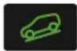 | Ifthislampilluminates,itindicatesthattheHDCsystemisinthestandby state.Ifthislampflashes,itindicatesthatthevehicleisunderthecontrolofHDC. |
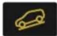 | TheHDCsystemhasdetectedafault. | |
| AutoHoldStatusIndicator |  | Theautoholdsystemisoperatingtoassistthedriver. |
INSTRUMENTSANDCONTROLS
| ElectronicParkingBrake (EPB)StatusIndicator |  | Ifthislampilluminates,itindicatesthattheEPBisenabled.Ifthislampflashes,itindicatesthatthevehicleisparkedonanexcessive slopeortheEPBsystemhasfailed.Pleasesecurelyparkthevehicleona saferoad. |
| ElectronicParking Brake(EPB)System MalfunctionWarning |  | TheEPBsystemhasdetectedafault. |
| BrakeSystem MalfunctionWarning |  | Thebrakesystemhasfailed.Pleasestopthevehicleassoonassafety permits,andturnofftheSTART/STOPSwitch. |
| ABSMalfunction Warning |  | TheABShasfailed.IfanABSfailureoccurswhiledriving,ABSoperationwillbesuspended,but normalbrakingwillstillbeavailable. |
| SystemFaultMessage Indicator |  | Thisindicatorisusedtoinformthedriverthatthevehiclehasastored warningmessage.Pleaseviewthefaultmessageorimportantnotesinthe informationcentre.Referto"InformationCentre"inthischapter. |
INSTRUMENTSANDCONTROLS
| Low-voltageBatteryChargingSystemMalfunctionWarning | 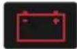 | Ifthislampilluminatesafterstartingthevehicle,itindicatesthatthe low-voltagebatterychargingsystemhasfailed.Ifthislampflashes,itindicatesthatthebatterypowerislow,anda promptmessageappearsintheinstrumentpack.Atthistime,thesystem willrestrictorturnoffsomeelectricaldevices.Pleasestartthevehicle immediatelytochargethebattery. |
| High-voltageBatteryPackLowBatteryWarning |  | Ifthislampilluminatesorflashes,itindicatesthatthehighvoltagebattery chargeislow.Wherepossiblepleasechargethehighvoltagebatterybefore thislampenterstheflashingstage. |
| High-voltageBatteryPackCutoffWarning | 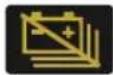 | Thehighvoltagebatteryisdisconnectedorisolated. |
| High-voltageBatteryPackMalfunctionWarning |  | Ifthislampilluminates,itindicatesthatthehighvoltagebatteryhasdetected afault.Ifthislampflashes,itindicatesthatthehighvoltagebatterytemperatureis toohigh.Pleasestopthevehicleassoonassafetypermitsandleavethe vehicleimmediately. |
| ChargingConnectionIndicator |  | Thevehicleisconnectedtoachargepoint. |
INSTRUMENTSANDCONTROLS
| ChargingStatusIndicator |  | Whenthevehicleisconnectedtoanexternalpowersupplyforcharging, thislampwillilluminateandextinguishafterchargingiscompleted. |
| DrivingPowerLimitedWarning |  | Thevehiclepowerhasbeenreduced. |
| PowerSystemMalfunctionWarning |  | Thevehiclehasafaultanditsperformanceislimited. |
 | Thevehiclehasaseriousfault.Pleasestopthevehicleassoonassafety permits,andturnofftheSTART/STOPSwitch. | |
| READYIndicatorThevehi |  ordriving. ordriving. | |
| DrivingModelIndicator |  | DisplaysheurrendrivingnodethevehicleNORMAL、SPORT、ECO. |
| BrakingEnergyRecoveryLevelIndicator |  | Displaysthecurrentbrakingenergyrecoverylevelofthevehicle. |
INSTRUMENTSANDCONTROLS
| ManualSpeedAssist SystemIndicator |  | TheManualSpeedAssistSystemisactivated. |
 | Ifthislampilluminates,itindicatesthattheManualSpeedAssistSystemis inthestandbystate.IftheManualSpeedAssistSystemhasafault,thelampwillflashyellowand thenextinguish. | |
| IntelligentSpeedAssist SystemIndicator |  | TheIntelligentSpeedAssistSystemisactivated. |
 | Ifthislampilluminates,itindicatesthattheIntelligentSpeedAssistSystem isinthestandbstate.IftheIntelligentSpeedAssistSystemhasafault,thelampwillflashyellow andthenextinguish. | |
| ManualSpeedAssist SystemSpeedIndicator |  | ThislampwillilluminatewhentheManualSpeedAssistSystemisenabled.'NNN'denotesthecurrentsettingvalueofthespeedlimit. |
| SpeedLimitSign Indicator |  | 'NNN'denotesthespeedvalueofspeedlimitsigncurrentlyrecognised. |
INSTRUMENTSANDCONTROLS
| SpeedLimitSignAdditionalInformationWarning |  | Thespeedlimitsigncurrentlyrecognisedhasadditionalinformation.Please payattentiontoit. |
| NationalSpeedLimit SignIndicator |  | Whentheoverspeedalarmorintelligentspeedlimitfunctionison,the nationalspeedlimitsignisrecognised. |
| AdaptiveCruiseControlSystemIndicator | 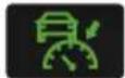 | TheAdaptiveCruiseControlSystemisactivated. |
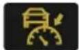 | TheAdaptiveCruiseControlSystemisinthestandbystate. | |
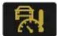 | TheAdaptiveCruiseControlSystemhasafault. |
INSTRUMENTSANDCONTROLS
| TrafficJamAssistSystemIndicator | 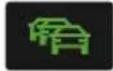 | TheT rafficJamAssistSystemisactivated. |
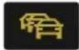 | Ifthislampilluminates,itindicatesthattheTrafficJamAssistsystemisin thestandbystate.Ifthislampremainsilluminatingafterflashingforawhile,itindicatesthat thesystemcannotworknormally. | |
| LaneAssistSystemIndicator | 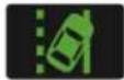 | Thelanedeparturewarningfunctionisonandmeetstheactivation conditions. |
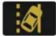 | Ifthislampilluminates,itindicatesthatthelanedeparturewarningfunction isinthestandbstate.Ifthislampremainsilluminatingafterflashingforawhile,itindicatesthat thesystemcannotworknormally. | |
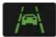 | Thelanekeepassistfunctionisonandmeetstheactivationconditions. |
INSTRUMENTSANDCONTROLS
 | Ifthislampilluminates,itindicatesthatthelanekeepassistfunctionisinthe standbystate.Ifthislampremainsilluminatingafterflashingforawhile,itindicatesthat thesystemcannotworknormally. | |
| ForwardCollision SystemIndicator |  | Ifthislampilluminates,itindicatesthatanyfunctionoftheForwardCollision Systemisoff.Ifthisindicatorilluminateswhenallthefunctionsisenabled,itindicatesthat theForwardCollisionSystemcannotoperatenormally. |
| RearDrivingAssist SystemIndicator * |  | TheRearDrivingAssistSystemisturnedoff,theradariscoveredorthe systemhasfailed,thecorrespondingpromptmessagewillappearinthe instrumentpack. |
INSTRUMENTSANDCONTROLS
| eCallsOSIndicator |  | Thesystemisreadyandanemergencyservicescall(eCall)isinprogress. |
 | Thesystemisstillcapableofsendingoutvehicleinformationmessageto thecallcentre,butothereCallcapabilitiesarelimitedduetoafaultinthe system. | |
 | TheeCallsystemhasfailedandnotoperational. |
Note: Therearesomecircumstanceswhereawarninglightmayilluminateorawarningmessageisdisplayed asanindicationofanissuewiththeassociatedsystem,thisdoesnotnecessarilyindicateafault.lfindoubt, pleaseseekadvicefromanMGAuthorisedRepairer.
INSTRUMENTSANDCONTROLS
LightsandSwitches
MasterLightingSwitch
text_image
3 2 1 4IAUTOLamp
2SideLampsandSwitchIllumination
3DippedHeadlamps
4LightsOFF
AUTOLamp
WhenthevehiclepowersystemisintheACCposition, theautolightingsystemdefaultstotheONposition(1). Theautolightingsystemwillautomaticallyswitchtheside lampsandswitchilluminationonandoffaccordingtothe intensityofcurrentambientlight.
Withthevehiclepowersystemswitchedtothe ON/READYposition,theautolightingsystemdefaults totheONposition(1).Theautolightingsystemwill automaticallyswitchthesidelamps,switchillumination anddippedheadlampsonandoffaccordingtotheintensity ofcurrentambientlight.
Note: This function is realized by fitting a sensor capable of monitoring exterior lighting conditions in realtime on your vehicle. The sensor is fitted in the centre of the fasci panel near the windscreen in some model. DONOT mask or cover this area, or the headlamps may automatically come on when not necessary.
INSTRUMENTSANDCONTROLS
SideLampsandSwitchIllumination
When the START/STOP switch is in the ACC position, turn them master lightings switch to position 2 to operate the side lamps and switch illumination.
When the START/STOP switch is in the ON/READ Y position, turn them master lightings switch to position 2 to operate the day timer running lamps, rearsidelamps and switch illumination.
WiththeSTART/STOPSwitchintheOFFpositionifthe lightingswitchisinposition2andthedriver'sdooris openedanaudiblewarningwillsoundtoalertthedriver, thesidelampswillremainon.
DippedHeadlamps
When the START/STOP switch is in the ON/READ Y position, turn them master lightings switch to position 3 to operate the dipped head lamps, sidelamps and switch illumination.
LightsOff
T urnthemasterlightingswitchtoposition4, this will switchoffallamps, releasing the switch will allow it to return to the AUTO switch position.
DaytimeRunningLamp
Thedaytimerunninglampsturnonautomaticallywhenthe START/STOPSwitchisintheON/READ Yposition.When thedippedheadlampsareswitchedon,thedaytimerunning lampsextinguishautomatically.
FollowMeHome
AftertheSTART/STOPSwitchisturnedoff,pullthelighting stalkswitchtowardsthesteeringwheel.Thiswillenable theFollowMeHomefunction,dippedbeamheadlamps andsidelampswillilluminatedependinguponthevehicle configuration.Itcanbesetonthentertainmentdisplay.
INSTRUMENTSANDCONTROLS
HeadlampLevellingManualAdjustment
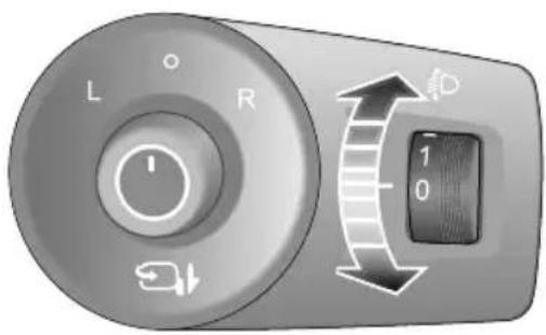
text_image
L R 1 0 DPosition0istheinitialpositionoftheheadlamplevelling adjustmentswitch.Theheadlamplevellingadjustmentcan bemadeasperthefollowingtableaccordingtothevehicle load.
| Location | Load |
| 0Driver,ordriver&frontpassenger. | |
| 1 | Alltheseatsoccupiedwithnoload. |
| 2 | Alltheseatsoccupiedplusanevenly distributedloadintheboot,ordriverwith fullload. |
| 3 | Driveronly,plusanevenlydistributedloadin theboot. |
INSTRUMENTSANDCONTROLS
MainBeamSwitch

T akecarenottodazzleoncomingvehicles whendrivingusingmainbeamheadlamps.
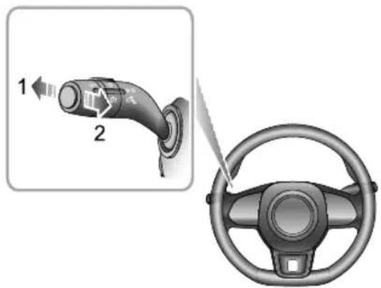
text_image
Diagram showing a car plug being inserted into a steering wheel, with labeled parts and directional arrows.HeadlampHigh/LowBeamSwitching
WiththeST ART/STOPSwitchintheON/READ Yposition anddippedheadlampsareswitchedon, pushthelever(1) towardtheinstrumentpaneltoturnonheadlamphigh beams. Thehighbeamindicatorlampininstrumentpack
illuminates, pushthelever(1)againorpullthelever(2)to switchtoheadlamplowbeams.
HighBeamFlash
T obriefyflashthehighbeamonandoff, pullthelever towardsthesteeringwheel(2) and then release.
INSTRUMENTSANDCONTROLS
AutoHighBeam

Theautohighbeamsystemservesonlyasan auxiliaryfunction. Thedrivermustcheckthe statusofthefrontlamps, andturnonthe frontlampswhennecessary.
Forexample: Themainbeammaynotbe turnedoffautomaticallyinthefollowing cases, thusmanualswitchingbetweenthe mainbeamanddippedbeamisrequired:
- Thewindscreenisdirty,brokenor obstructedbyotherobjectsblockingthe viewofthesensor.
•Thelampsofothervehiclesaremissing, damaged,blockedorcannotbedetected duetoweatherandotherreasons. - Whenpedestrians, non-motorvehicles and other objects with no obvious lightor reflected light are encountered.
- When the headlamps and taillamp sof other vehicles cannot be detected due to sensoriew being impaired due
undulatingroadconditionssuchasbends, dipsorhills.
- Whenthecarisdrivingonawindingroad ormountainousroad.
Theautohighbeamsystemisdesignedtodetectthelight intensityinformationofthevehicleinfronusingthevehicle forwardcameraandswitchthemainbeamonoroffwhen certainconditionsaremeWhentheautohighbeam systemisenabled,theautohighbeamindicatorinthe instrumentpackilluminates.Afterthevehicleisstarted, theautohighbeamsystementersthereadystateofwork. Itcanbesetonthentertainmentdisplay.
the automation control system will
automaticallyurrorthemairbeamwherthesurrounding environmentisdarkandthereisnolightdetectedfrom anyvehiclesahead,oroncomingvehicleswhenthe surroundingenvironmentisbrightenoughorthesystem detectstheheadlampsortaillampsofthevehicleahead oroncomingvehicles,thesystemwillautomaticallyturn offthemainbeam.
INSTRUMENTSANDCONTROLS
T oenabletheautohighbeamsystem, the following conditionsmustbemet:
I ThemasterlightingswitchmustbeintheAuto positionandthedippedbeamlampsswitchedonvia automaticcontrol.
2Thevehicleisrunningandthespeedisabove25mph (40km/h).
If the following conditions are met, the vehicle will automatically exit the autohigh beams system.
- Whentheautohighbeamsystemisenabledandthe dippedbeamlightsareautomaticallyturnedon,thehigh beamswitchisoperated.
- Whentheautohighbeamsystemisenabledandthe mainbeamlightsareautomaticallyturnedon,thehigh beamswitchisoperated.
- Whentheautohighbeamsystemisenabledandthe mainbeamlightsareautomaticallyturnedon,thehigh beamflashswitchisoperated.
If the system exits, quickly push the direction indicator/main beam switch (main beam 'ON') towards the instrument pack twiceto enter the autohigh beam
systemagain.Y oucanonlyexittwotimesinoneignition cycle.Ifyouexitgreaterthanorequaltothreetimes,you willnotbeabletoenablethisfunctionagaininthecurrent startcycle.Theautohighbeamsystemcanbereactivated afterthenextstartcycle.
IMPORTANT
Theautohighbeamfunctionusesdatafromthefront viewcamera,alwayskeepthewindscreencleanand freefromresidueinthisareatomaintainoptimum performanceofthissystem.Anydamageinthisarea, suchasstonechipsmustberepairedattheearliest convenience.
INSTRUMENTSANDCONTROLS
DirectionIndicatorSwitch
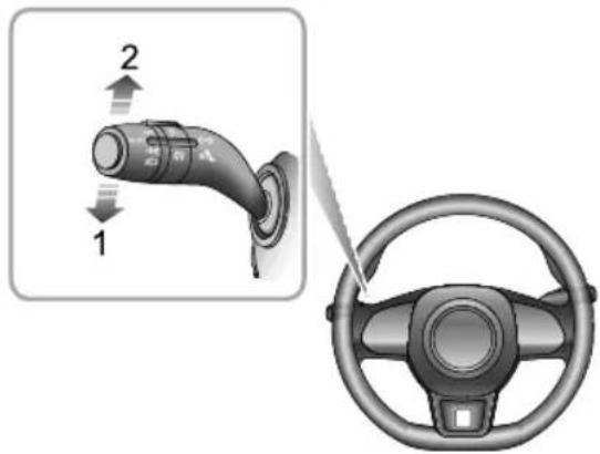
text_image
Diagram showing a car charger connected to a steering wheel, with labeled parts and directional arrows indicating movement.MovetheleverdowntoindicateaLEFTturn(1).Movethe leveruptoindicateaRIGHTturn(2).Thecorresponding GREENindicatorlampintheinstrumentpackwillflash whentheturningsignallampsareworking.
Rotatingthesteeringwheelwillcanceltheindicator operation(smallmovementsofthesteeringwheelmay notoperatetheselfcancelling).T oindicatealanechange, movetheleverbrieflyandrelease,theindicatorswillflash threetimesandthencancel.
FogLampSwitch

Foglightsshouldonlybeusedwhenvisibility isbelow100m-otherroaduserscouldbe dazzledinclearconditions.

text_image
1RearFogLamp
WiththeST ART/STOPSwitchintheON/READYposition and the headlampson, turn the foglamp switchtoposition
INSTRUMENTSANDCONTROLS
I, this will turn on therear foglamp, releasetheswitch to allow it to return to the last position. The indicator illuminates in the instrument panel when therear foglamp is on.
HazardWarningLamp
Pressthehazardwarninglampbuttontoturnon thehazardwarninglamps.Theturningsignallampsand directionindicatorlampswillflashtogether.Pressthe buttonagaintoswitchoffthehazardwarninglamps.All turningsignallampsanddirectionindicatorlampswillstop flashing.
INSTRUMENTSANDCONTROLS
WipersandWashers
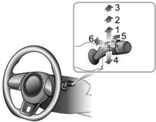
text_image
Diagram showing car steering wheel and valve mechanism with numbered directional arrows indicating flow or movementWindscreenWiperOperation
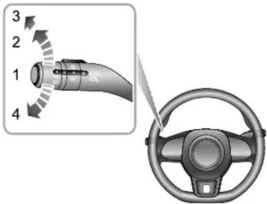
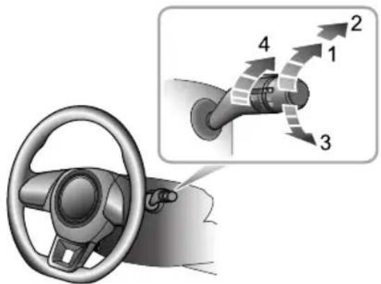
Thewipersandwasherswillonlyoperatewiththevehicle powersystemintheACC/ON/READYposition.Operate thelevertoselectdifferentwipespeeds:
- Intermittentwipe(I)
-
Slowwipe(2)
-
Fastwipe(3)
•Singlewipe(4)
•Automaticwipeintervaladjustment * /Rainsensor sensitivityadjustment *(5)
•Programmedwash/wipe(6)
IntermittentWipe
BypushingtheleveruptothelIntermittentwipeposition (1), thewiperswilloperateautomatically. T urntheswitch (5) * toadjusttheintermittentwipefrequency. Thisspeed will also changewith the vehiclespeed. Asthevehicle speed increases, thewiperfrequency increases. Asthe vehiclespeed decreases, thewiperfrequency decreases.
Somemodelsareequippedwitharainsensorfittedtothe interiorrearviewmirrorbasetodetectvaryingamounts ofwaterontheoutsideofthewindscreen.Withautomatic wipe,thevehiclewilladjustthewipingspeedaccordingto thesignalsprovidedbyrainsensor.T urntheswitch(5) toadjustthesensitivityofrainsensor.Asthesensitivity increases,thewipingintervaldecreases.
Note: Immediately operating the wiperonetime can be achieved by increasing the sensitivity of frainsensor.
INSTRUMENTSANDCONTROLS
Iftherainsensordetectscontinuousrainwater,the wiperwillkeepworking.Whennorainisdetected,it isrecommendedtoswitchoffautomaticwipe.
SlowWipe
Bypushingtheleveruptotheslowwipeposition(2), the wiperswilloperateslowly. Movethelevertore-select the wipespeed.
FastWipe
Bypushingtheleveruptothefastwipeposition(3), the wiperswilloperatefast.Movethelevertore-selectthe wipespeed.
SingleWipe
Pressingthelever(4)downandreleasingwilloperate asinglewipe,iftheleverishelddown,thewiperswill operatecontinuouslyuntiltheleverisreleased.
Note: Whenthecarisstationary, if the bonnet is opened, the frontwiper/washer will stop work immediately.
IMPORTANT
- Avoidoperatingthewipersonadrywindscreen.
• Infreezingorextremelyhotweatherconditions, makesurethatthewiperbladesarenot frozen/adheredtothewindscreen.
• Inwinter, removesnoworicefromaroundthearms and blades, includingthewipedareaofthescreen.
ProgrammedWash/Wipe
Pullingthelevertowardthesteeringwheel(6)willoperate thewindscreenwashers. Afterashortdelay,thewipers willcommenceoperatinginconjunctionwiththewashers.
Not the wipers continue operating for further three wipes after the lever is released. After several seconds, there will be further wipet remove any fluiddraining down the screen.
INSTRUMENTSANDCONTROLS
IMPORTANT
Ifthewashersfaltodeliverthescreenwashsolution (dirtoricemayhaveblockedthejets), releasethe leverimmediately. This will prevent the wipers from operating, and the consequent risk of visibility being impaired by dirt smearing across the unwashed windscreen.
RearWindowWiperOperation
text_image
Diagram showing a car steering wheel and its directional control valve mechanism with numbered arrows indicating flow or movement.Therearwindowwiperandwasherwillonlyoperate withthevehiclepowersystemintheACC/ON/READY position.Operatethelevertoselectdifferentwipespeeds:
- Intermittentwipe(I)
•Washandwipe(2)
•Washandwipe(3) - Intermittentwipefrequencyadjustment(4)
INSTRUMENTSANDCONTROLS
IntermittentWipe
T urntherearwindowwiperswitchointermittentwipe (1), therearwindowwiperwilloperate, after 3 consecutive wipes, thewiperswillenterintointermittentmode. The timeperiodbetweenthewipescanbeincreased/decreased via theintermittentwipefrequencyadjustmentswitch(4).
WashandWipe
T urntherearwindowwiperswitchtowashandwipe(2) positionandhold,therearwindowwiperandwasherwill operate,therearwindowwiperwipesquickly.releasethe switchallowingittoreturntointermittentwipe(1),the rearwindowwasherwillstopoperating.
T urntherearwindowwiperswitchtowashandwipe(3) andhold,therearwindowwiperandwasherwilloperate. releasetheswitchallowingittoreturntoOFFposition, therearwindowwasherwillstopoperating,andtherear windowwiperwipesfor3times,afterseveralseconds,the wiperwillwipeoncemoretoremovethewasherfluidon thewindscreen.
Note: Whenthetailgate is opened, rear windowwiper operations will be disabled.
Note: Whenthewindscreenwipersareswitchedon, if theshiftcontrolknobismovedto, orintheRposition, therearwindowwiperwilloperate.
INSTRUMENTSANDCONTROLS
SteeringSystem
AdjustmentofSteeringColumn

DONOTattempttoadjusttheangle of thesteeringcolumnwhilethevehicleisin motion. Thisisextremelydangerous.

natural_image
Interior view of a car showing steering wheel, dashboard, and steering wheel with a directional arrow indicating left-hand rule (no text or symbols present)T oadjusttheangleofthesteeringcolumntosuityour drivingposition:
I Fullyreleasethelockinglever.
2Holdthesteeringwheelinbothhandsandtiltthe steeringcolumnupordowntomovethewheelinto themostcomfortableposition.
3Onceaccomfortabledrivingpositionhasbeenselected, pullthelockingleverfullyuptolockthesteering columnintoitsnewposition.
ElectricPowerSteering

If the electric power steering fails or cannot operate the steering will appear very heavy, this will affect drivings safety.
Theelectricpowersteeringsystemonlyworkwhenthe vehicleisinREADYmode.Thesystemoperatesviaa motorwithassistancelevelsautomaticallyadjustedbased onvehiclespeed,steeringwheeltorqueandsteeringwheel angle.
INSTRUMENTSANDCONTROLS
IMPORTANT
Holdingthesteeringwheelonfulllockforlongperiods willresultinareductioninpowerassistancecausinga heavierfeeltothesteeringforashortperiodoftime.
INSTRUMENTSANDCONTROLS
Horn
natural_image
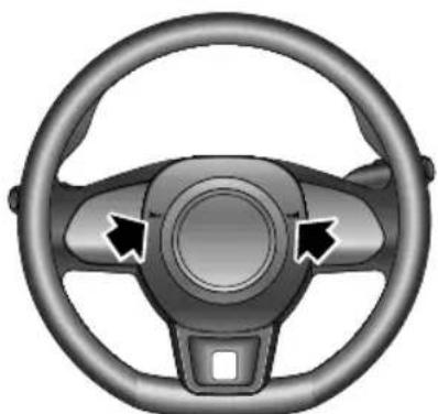
Top-down view of a car steering wheel with three arrows indicating clockwise direction (no text or symbols)Pressthehornbuttonareaonthesteeringwheel(as indicatedbythearrow)tooperatethehorn.
Note: The vehicle horn switch location and the driver's air bag are located in close proximity on the steering wheel. The illustrations show the position of the horn switches, please ensure that you press in this are a
avoid any potential conflict with the operation of the airbag.
IMPORTANT
T oavoidpossibleSRSissues, pleasedonotpresswith excessiveforceorhittheairbagcoverwhenoperating thehorn.
INSTRUMENTSANDCONTROLS
RearviewMirrors
Thevehicleisfittedwithrearviewmirrors,theseconsist ofadoormirrorfittedtoeachdoorandacentrally mountedinteriormirror .Rearviewmirrorsreflect situationsdirectlybehindoronbothsidesofthevehicle thusexpandingthedriver'sfieldofvision.
Therearviewmirrorsaresafety-criticalparts.Properuse andreasonablemirrorangleadjustmentcanimprovethe driver'sdrivingsafetyandcomfort.
ExteriorDoorMirrors
Note: Objectsviewedinexteriordoormirrorsmay appearfurtherawaythantheyactuallyare.
Themirrorscanbeelectricallyfoldedbacktowardsthe sidewindowsintoa'park'positiontoenablethecarto negotiatenarrowopeningsandavoidcollisions.
Inadditiontothefoldingfunction,themirrorangleofthe exteriordoormirrorscanbeadjustedelectronically.Some vehiclesarealsoequippedwithmirrorheatingfunction.
MirrorGlassHeating
The doormirror have integral heating elements which disperse ice or mist from the glass. The heating elements operate while the Heated Rear Window is switched on.
Note: The heating element so frear window and mirror will only work when the powers system is in READY mode.
INSTRUMENTSANDCONTROLS
ElectricDoorMirrorGlassAdjustment
natural_image
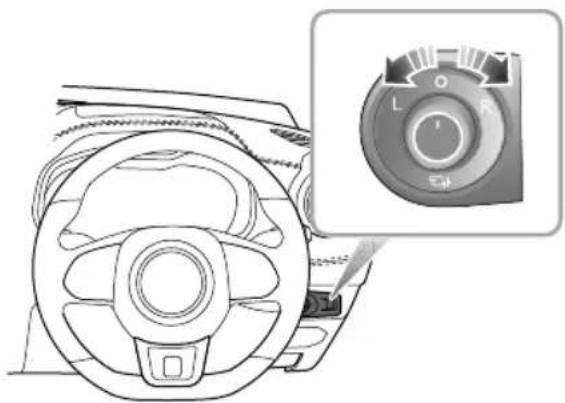
Diagram of a car steering wheel with a close-up inset showing the dial (no text or symbols present)•Themirroradjustmentfunctionwillworkwiththe START/STOPSwitchinallmodes,includingOFF ,ACC andON/READ Y .
- Rotatetheknobtoselectleft(L)orright(R)rearview mirror.
- Movetheknobinthedesireddirectiontoadjustthe angleoftheexteriormirrorglass.
- Upon completion of the headjustment, rotatetheknob back to the central position, this will ensure no accidental adjustment of them mirror.
ElectricFoldingofDoorMirror
natural_image
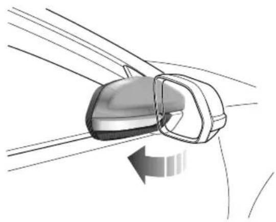
Diagram of a car frontview mirror showing the blade and side mirror (no text or symbols)Rotatetheknobtothemiddleposition,andpushthe knobdown. Thedoormirrorswillbefoldedautomatically. Pushingtheknobdownwardsagainwillreturnthemirrors totheiroriginalposition.
Operatingthekeyfoblock/unlockbuttonswillfold/unfold thedoormirrors.
Note: Electrical folding doormirrorsthath have been moved from their positions by manual or accidental means must be reset by operating the knob to complete fold and deployment on time.
IMPORTANT
- Doormirroglassadjustmentsanddoormirror foldingareoperatedbyelectricalmotors.Operating themdirectlybyhandmaydamagetheinternal components.
- Washingorflushingdoormirrorswithhighpressure waterjetsorcarwashesmayresultinelectrical motorfailure.
ManualAnti-dazzleInteriorRearviewMirror
Adjustthebodyoftheinteriorrearviewmirrortoachieve thebestpossibleview.Theanti-dazzlefunctionofthe interiorrearviewmirrorhelpstoreduceglarefromthe headlampsoffollowingvehiclesatnight.
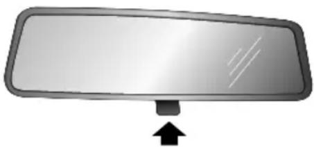
natural_image
Simple diagram of a rectangular mirror with an arrow pointing upward (no text or symbols)Movetheleveratthebaseofthemirrorforwardto‘dip’ themirrorandachievetheanti-dazzlefunction.Normal visibilityisrestoredbypullingtheleverbackagain.
Note: In some circumstances, the view reflected in 'dipped' manual mirror can confuseth driver as to the preciselocation off following vehicles.
INSTRUMENTSANDCONTROLS
Sunvisor

Thevanitymirroronthedriversideshould onlybeusedwhenthecarisstationary.
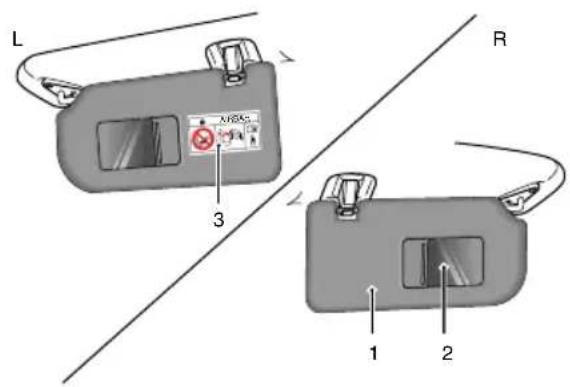
Sunvisors(1)arearrangedontheroofaheadofboththe driverandthefrontpassenger.Somemodelshavevanity mirror(2),dependingonthevehicleconfiguration.For themodelswhichhavevanitymirror,pullthesunvisor downwardandslidethecoverasidetousethevanity mirror.
text_image
L 3 R 1 2Note:Warningsandinstructionsonuseofchild restrain(b)attachedbdo side of passengersunvisor.
NEVERusearwardfacinghildestraintsomeat protected by an ACTIVEAIRBAGrfrontoftDEATH or SERIOUSINJURYtotheCHILDcanoccur.Refer to 'DisablingthePassengerAirbag'.
INSTRUMENTSANDCONTROLS
Windows
text_image
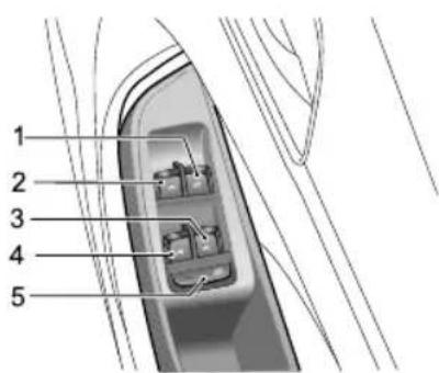
1 2 3 4 5FrontRightWindowSwitch
2FrontLeftWindowSwitch
3RearRightWindowSwitch
4RearLeftWindowSwitch
5 RearWindowIsolationSwitch
WindowOperation
Ensurechildrenarekeptclearwhenraisingor loweringawindow.
Improperuseoractivationoftheelectric windowsbychildrencouldcauseseriousharm orevendeath.Itistheresponsibilityofthe driverandadultpassengerstoensurethat whencarryingchildrenthenecessarysteps aretakentoisolatethewindowoperation. Thisshouldincludetheremovalofthekey whenchildrenareleftaloneinthevehicle.
Pushtheswitch(1-4)downtolower,andpulltheswitchuptoraisethewindow. Thewindowwillstopmovingassoon astheswitchisreleased(unlessthe'One-T ouch'function isactive).
Note: The front and rear passenger windows can also be operated by individual window switches, mounted one each do therear window switches will not operate if therear windowisolations switch has been activated.
INSTRUMENTSANDCONTROLS
Note: The electric windows can be operated with the vehicle powersystem in the ACC, ON and READY positions. (Forsafety: door should be closed).
RearWindowIsolationSwitch
Pressthebutton(5)toisolatetherearwindowcontrols, pressagaintorestorecontrol.
Note: It is recommended that you ISOLATE therear windowswitches when carrying a child.
"One-T ouch"Down
Thedriver'swindowcontrolswitch(1)has2positions. Shortpressthewindowcontrolswitchtothe"2"position andrelease. Thewindowautomaticallydescendstofully open. Windowmovementcanbestoppedatdesired positionatanytimebyoperatingthecorrespondingswitch duringdescent.
"OneT ouch" Upwith "Anti-T rap"
Thedriver'swindowcontrolswitch(1)hasthe "one-touch"upfunction.Liftingtheswitchtothe"2"
positionforashorttimeandreleasingwillautomatically closetehindowcompletely.Windowmovementcan bestoppedatadesiredpositionatanytimebybriefly operatingtheswitchagain.
The "Anti-T rap" functionisasafetyfeaturewhichprevents thewindowfromfullyclosingifanobstructionissensed-ifthishappensthewindowwillopenslightlytoallowthe obstructiontoberemoved.
Note DONOToperatethepowerwindowcontrols continuously severallmeshortimframe, otherwisethepowerwindowcontrolsmaybedisabled toprotectthemotor. If this occurs, please wait a few seconds until the motor coolsdown in the case of the driver's window with "One T ouchand Anti-Trap" please wait 30 seconds prior to operation some cases it may take 30 minutes to completely cooldown, during which timethenegative battery lead should not be disconnected.
Note: If the battery is disconnected, the "One-T ouch" and "Anti-Trap" features will belost. T orestore this feature, fully closetethindowandholdtheswitch for
INSTRUMENTSANDCONTROLS
5seconds, and then fully open the window and press the switch for 5 seconds.
INSTRUMENTSANDCONTROLS
Sunroof \*
Thesunroofconsisttwopiecesofglassandonesunshade. Thefrontglasscanbeopenedbyslidingortilting,therear oneisfixedandcannotbeopened,andthesunshadecan slideopen.
Instructions

DONOTallowpassengerstoleanoutofan opensunroofwhilstthevehicleisinmotion. Injuriesmayoccurfromobjectssuchastree branches.

Safetyofthevehicleoccupantsmustbe observedatalltimes.DONOTallowlimbsto beplacedinthemovingpathofthesunroof atanytime,injurymayoccur.
- Avoidfullyopeningthesunroofduringgrainshowers.
- Itisadvisednottoopenthesunroofathighspeeds.
-
Wherepossible, pleasecleananyresidualwateror raindropsoffthesunroofpriortoopening.Failureto dosomayresultinwaterenteringthecar.
-
DONOTuseabrasivematerialstocleanthesunroof glass.Usealcoholbasedsolvent.
- DONOTholdtheoperatingswitchintheopen/close positionforanylengthoftimeafteroperationis complete,thiscoulddamagetheelectricalcomponents.
- Cleanthesunroofregularlytomaintainoperationand performance.VisitanMGAuthorisedRepairerfor serviceasrequired.
SunroofOperation
text_image
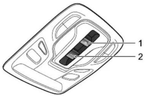
Technical diagram of a device casing with labeled parts 1 and 2WhentheSTART/STOPSwitchissettoACCor ON/READY, youcanoperatethesunroof.
Switch1 is used to operate the sunroof sunshade, and switch2 is used to operate the sunroof glass. The operational function is identified by the icon on the switches.
SunroofGlassOperation
OpentheSunroofGlassbyTilting
flowchart
graph TD
    A["Step 1"] --> B["Step 2"]
    B --> C["Step 3"]
    C --> D["Step 4"]
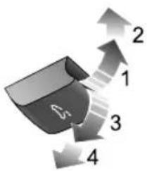
Pushthesunroofglassswitchupwardtothe1stposition (1)andhold,thesunroofwilltiltopenmanually.Y oucan stopthemovementofthesunroofatanytimebyreleasing theswitch.
Pushtheglassswitchwithslightlyharderforcetomovethe switchtoits2ndposition(2)andthenrelease,thesunroof willautomaticallyopencompletely.
ClosetheSunroofGlassbyTilting
Pullthesunroofglassswitchdownwardtothe1stposition (3)andhold,thesunroofwillclosemanually.Youcanstop themovementofthesunroofatanytimebyreleasingthe switch.
INSTRUMENTSANDCONTROLS
Pulltheglassswitchwithslightlyharderforcetomovethe switchtoits2ndposition(4)andthenrelease,thesunroof willautomaticallyclosecompletely.
OpentheSunroofGlassbySliding
text_image
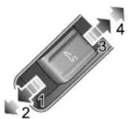
1 2 3 4Pushthesunroofglassswitchbackwardtothe1stposition (3)andhold,thesunroofwillslideopenmanually.Y oucan stopthemovementofthesunroofatanytimebyreleasing theswitch.
Pushtheglassswitchbackwardwithslightlyharderforce tomovetheswitchtoits2ndposition(4)andthenrelease, thesunroofwillautomaticallyopenfully.Y oucanstopthe movementofthesunroofatanytimebypushingtheswitch backwardagain.
ClosetheSunroofGlassbySliding
Pushthesunroofglassswitchforwardtothe1stposition (1)andhold,thesunroofwillclosemanually.Y oucanstop themovementofthesunroofatanytimebyreleasingthe switch.
Pushtheglassswitchforwardwithslightlyharderforceto movetheswitchtoits2ndposition(2)andthenrelease, thesunroofwillautomaticallyfullyclose.Y oucanstopthe movementofthesunroofatanytimebypushingtheswitch forwardagain.
Note: Duetothedesignofthesunrooftheremay beoccasionswhereusingthemanualclosefunction providesavisualimpressionthattheglassisfully closed, thismaynotbethecase, itisrecommended tousethe2ndpositiontoautomaticallyclosethe sunroofglasswhenitneedstobecompletelyclosed
INSTRUMENTSANDCONTROLS
SunroofSunshadeOperation
text_image
1 2 3 4OpentheSunshade
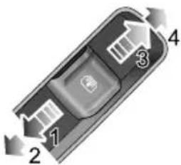
Pushthesunroofsunshadeswitchbackwardtothe1st position(3)andhold,thesunshadewillslideopenmanually. Youcanstopthemovementofthesunshadeatanytimeby releasingtheswitch.
Pushthesunshadeswitchbackwardwithslightlyharder forcetomovetheswitchtoits2ndposition(4)andthen release,thesunshadewillautomaticallyopenfully.Y oucan stopthemovementofthesunshadeatanytimebypushing theswitchbackwardagain.
ClosetheSunshade
Pushthesunroofsunshadeswitchforwardtothe1st position(1)andhold,thesunshadewillclosemanually. Youcanstopthemovementofthesunshadeatanytime byreleasingtheswitch.
Pushthesunshadeswitchforwardwithslightlyharderforce tomovetheswitchtoits2ndposition(2)andthenrelease, thesunshadewillautomaticallyfullyclose.Y oucanstop themovementofthesunshadeatanytimebypushingthe switchforwardagain.
Note: If the vehicle is to be parked directly sunlight for length of time it is recommended that the sunshade be closed to protect the interior trim components from damage, and to help regulate the incartemperatures.
Anti-pinchFunction
Thesunroofandsunshadefeaturean“Anti-Pinch” function, thisisasafetyfeaturewhichprevents the sunrooforsunshadefromfullyclosingwhilstinthe automaticmodeifanobstructionissensed-ifthis happensthesunroof/sunshadewillopenslightlytoallow theobstructiontoberemoved.
INSTRUMENTSANDCONTROLS
Note: Forsomevehicles, if the anti-pinchist riggered threetimesin succession, the sunroof/sunshade cannot be operated in automatic mode. You can only movethesunroof/sunshadeswitch to the 1st position and hold it to operate in manual mode. The automatic operation function will be restored after the sunroof/sunshade is completely closed once.
ForciblyClosingtheSunroof(over-ridingtheanti pinch)
T oforctibyclosethesunroofglassafterananti-pinch intervention, gently slidetheglassswitchforwardstothe lstpositionandholdinpositionuntilthesunroofglassis fullyclosed.
Note: The antipinch function is suspended during this operation.
ForciblyClosingtheSunshade(over-ridingtheanti pinch)
T oforctibyclosethesunshadethathasreopeneddueto activationofanti-pinchfunction:gentlyslidethesunshade
switchforwardstothe I stpositionandholdituntilthe sunshadeclosesfully.
Note: The antipinch function is suspended during this operation.
LinkagebetweenSunshadeandSunroofGlass
To prevent the sunshade from being exposed, the sunshade will move together with the sunroof glass on unit when the sunroof is opened. To closet the sunshade, the sunroof glass will close first.
SunroofInitialisation
Intheeventofapowerfailureorbatterydisconnection whenthesunroofglassorsunshadeisinmotion,the sunroof/sunshadewillrequireinitialisationwhenthepower isrestored.
T ocarryoutthesunroofglassinitialisationoperation: Fullyclosetheglass-gentlyslidetheswitchforwardto the2ndpositionandholdinpositionfor 10seconds. The sunroofwillopenapresetamountandstop, itwillthen closeautomatically-thesunroofglassistheninitialised.
During the whole process, the switch must remain in the 2nd position.
T ocarryoutthesunshadeinitialisationoperation:
Fullyclosethesunshade-slidethecloseswitchforward tothe2ndpositionandholdinpositionfor10seconds. Thesunshadewillopenapresetamountandstop,itwill thencloseautomatically-thesunshadeistheninitialised. Duringthewholeprocess,theswitchmustremaininthe 2ndposition.
ThermalProtection
T opreventthesunroofglassmotorandthesunshade motorfrombeingoverheatedanddamaged,themotors aredesignedwithathermalprotectionfunction.
Afterthethermalprotectionfunctionisactivated, the sunroof/sunshadedoesnotrespondtootheroperations excepttheclosingoperation. Afterthemotorhascooled downandexitsthethermalprotectionstate, thesunroof canbeoperatednormallyuntilthenextthermalprotection event.
INSTRUMENTSANDCONTROLS
InteriorLight
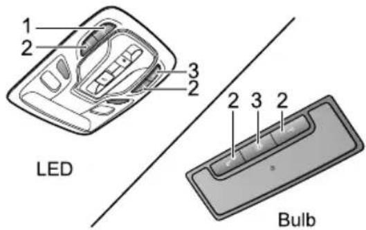
According to different configurations of the vehicles, the front interior lamp may feature bulbar LED configurations.
text_image
1 2 3 2 LED 2 3 2 BulbI MainManualControlSwitchofFront/RearInterior Lamps
2ManualControlButtonofCorrespondingFront InteriorLamp
3AutomaticControlButton
Pressswitch | toturnonthefrontandrearinteriorlamps, pressagaintoturnoff.
Presseitherofthebuttons2toturnonacorresponding frontinteriorlamp,pressagaintoturnoff.
Inadditiontothemanualcontroloftheinteriorlamps, someoperatingconditionswillactivateanautomatic controlfunction.Pressbutton3toturnonorturnoffthe automaticcontrol.
Interiorlightilluminationoccursautomaticallywhenever thefollowingoccur.
•Thecarisunlocked.
•Anydoorisopened.
•Thevehiclepowersystemisswitchedoff,providingthe vehiclelightsensordetectsthattheambientlightlevel isloworthesidelightshavebeenilluminatedduringthe previous30seconds.
Note: If a door is open form more than a certain period of time, the front interior lamp will be switched off automatically to avoid battery drain.
PowerSocket
FrontPowerSocket

Pleaseensurethesocketblankingplugis insertedwhenthepowersocketisnotinuse. Thiswillensurenodebrisorforeignobjects enterthesocketpreventingitsuseorcause shortcircuits.

The 12Vpowersockethasavoltagerating of 12V, and themaximumpower of 120Watt, please DONOTuseanyelectrical appliance that exceed this rating.

Extendeduseoftheaccessorypowersocket andUSBsocketwhenthevehiclepower systemisswitchedoffwillcausepremature dischargingofthevehiclebattery.
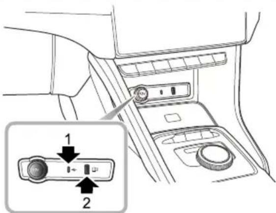
text_image
Diagram of car interior air intake with labeled ports and directional indicator (1) and (2)The 12Vpowersocketislocatedinfrontoftheshift controlknobassemblyinthecentreconsole.Itcanbe usedasapowersupplywhentheST ART/STOPSwitchis intheACCorON/READYpositionswhentheblanking plugisremoved.
LocatedtotherightofthepowersocketaretwoUSB ports. Bothofthemcanbeusedtoprovidea5Vpower supplyoradatatransmissionconnection.
INSTRUMENTSANDCONTROLS
Note: Duetodifferencesinconfigurationthecharging functionoftheUSBportwillbeslower.
Note: The vehicle is not supplied with a cigar lighter. If required please contact your local MGA authorised Repairer.
RearUSBPorts
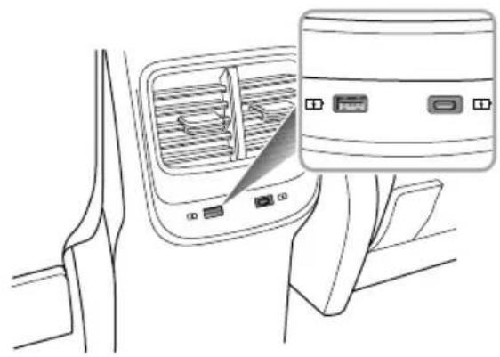
natural_image
Line drawing of a car interior showing the dashboard and rearview panel with no visible text or symbolsTherearetwoUSBportslocatedattherearofthecentre console, theseprovidea5Vpowersourceasapower outlet.
Note: Duetodifferencesinconfigurationthecharging functionoftheUSBportwillbeslower.
T opUSBPort
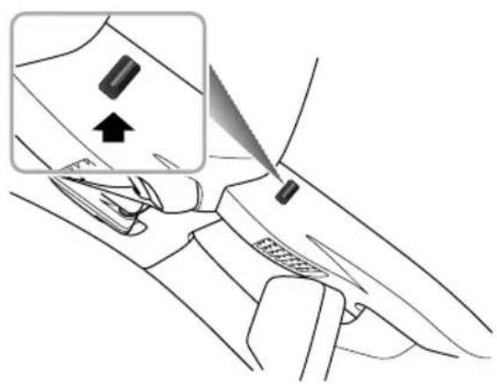
natural_image
Diagram of a car interior showing hand positioning and tool insertion (no text or symbols)INSTRUMENTSANDCONTROLS
ThereisalsooneUSBportlocatedintherearviewmirror mountingtrimcover, thisprovidesa5Vpowersource.
Note: Duetodifferencesinconfigurationthecharging functionoftheUSBportwillbeslower.
INSTRUMENTSANDCONTROLS
WirelessChargingSystemforMobile Phones \*
The wireless charging function for a mobile phone is realized without the necessity for a connection cable. It is achieved using electromagnetic induction.
Note: The wireless charging function does not apply to all mobile phones, only brands/models with wireless charging function.
WirelessChargingofMobilePhones
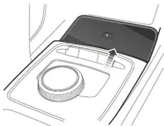
natural_image
Diagram of a car interior showing the dashboard and seat area with a directional arrow (no text or symbols)Thewirelesschargingareaislocatedintheareashown inthefigure.Thechargingfunctionisenabledwhenthe START/STOPSwitchisplacedintheACC/ON/READY positions.Placethephonefaceuphorizontallyinthe chargingarea,whichcanbeusedforwirelesscharging.
Note: Onlyonemobilephonecanbechargedata time.
INSTRUMENTSANDCONTROLS
Note: Onbumpyroads, the wireless charging function of themobilephonemay intermittently stop and resume. If themobilephonedeviates from the charging area and stops charging, it will need to be placed back in there chargeable area.
Note: Thesizeofeachbrandofmobilephoneis different, and the position of the charging coil on the mobile phone is different. Please adjust the position of the mobile phone accordingly. In addition, the case of some mobile phones may have an impact on wireless charging. It may be necessary to adjust or remove the caseto achieve wireless charging.
Ifthemobilephonecannotbechargedcorrectly,please makesurethatthereisnoforeignmatterinthewireless chargingareaorwaitforthewirelesschargingareatocool downbeforefurtherattempts.Ifitstillfails,seekanMG AuthorisedRepairer.
IMPORTANT
Whenthewirelesschargingsystemofthemobilephone isbeingused,makesurethatthesmartkeyis20cmor moreawayfromthewirelesschargingarea.
Donotplacecoins,ICcards,metalkeys,orother itemswithalargeamountofmetalcompositioninthe wirelesschargingareawithyourphone.Thismayresult inthefailureofwirelesschargingfunctionandcreatea safetyhazard.
INSTRUMENTSANDCONTROLS
StorageDevices
Instructions
- Please close all storage devices when the vehicle is in motion. Leaving these storage devices open may cause personal injury in cases of sudden start-off, emergency braking or a car accident.
- Donotplaceflammablematerialssuchasliquidor lightersinanystoragedevices.Theheatinhot conditionsmayigniteflammablematerialsandresultin afire.
GloveBox
natural_image
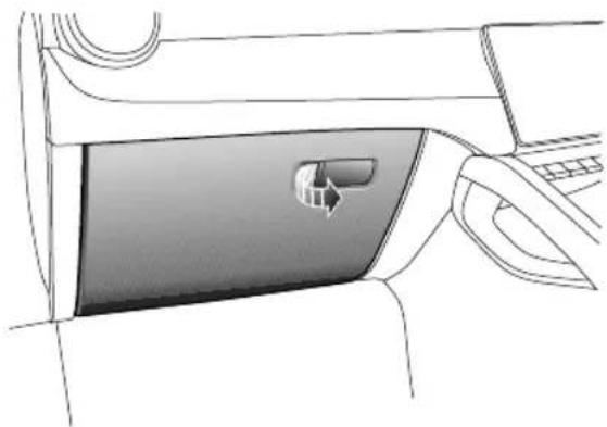
Diagram of a car interior showing the door handle and seat area (no text or symbols)T oopentheglovebox, pullthehandleontheglovebox cover(asindicatedbythearrow).
Pushtheboxcoverforwardtoclosetheglovebox.Make surethegloveboxisfullyclosedwhenthevehicleisin motion.
INSTRUMENTSANDCONTROLS
CentreConsoleArmrestBox
natural_image
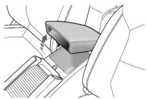
Mechanical diagram showing a car seatbelt buckle assembly with no text or symbolsLiftthearmrest(arrowed)toopenthecompartmentcover. Putthecoverdowntocloseit.
Loadspace

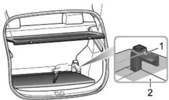
DONOTplacearticlesontherearparcel shelf,theycouldmovecausingpersonal injuryintheeventofanaccident emergencybrakingorhardacceleration.
natural_image
Diagram of a car interior showing a tray, seat, and mechanical component with numbered parts (1 and 2), no text or symbols present.Therearparcelshelfisconnectedtothetailgateusing strapsandhooks. Whenopeningthetailgate, theshelfwill automaticallyberaised.
INSTRUMENTSANDCONTROLS
Thesparewheel/tyrerepairkitandtoolkitarestowed beneaththeloadspacecarpet,liftthecarpetforaccess. Alwaysrefitthecarpetafteruse.
Inaddition, Theloadspacecarpetheightcanbeadjusted by using the carpetbracket (figure 1,2).
INSTRUMENTSANDCONTROLS
CupHolder

Donotplacehotdrinksinthecupholder whilstdriving.Spillagemayresultinpersonal injuryordamage.
CentreConsoleCupHolder
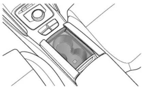
natural_image
Line drawing of a car interior showing the dashboard and seat area (no text or symbols)Thecentreconsolecupholderissituatedatthefrontend ofthecentreconsolearmrestassembly.
INSTRUMENTSANDCONTROLS
RoofLuggageRack \*

RoofloadsMUSTNOTexceedthemaximum authorisedload. Thismayleadtoinjuryor vehicledamage.

Looseorimproperlyfixedloadsmayfallfrom theroofluggagerackandleadtoanaccident orcauseinjury.

When heavy or large items are carried on the offluggagerackit may lead to changes in steering, handling and braking characteristics. Please avoid sharp maneuvers, heavy braking and excessive acceleration.
Payattentiontothefollowingwhenusingtheroofluggage rack:
- Fixloadstowardsthefrontoftheroofasfaraspossible, anddistributetheroofloadevenly.
- DONOTuseautomaticcarwasheswithloadsontheroofluggagerack.
• The overall height of the car is different when loads are fitted to other of fluggagerack. Please ensure there is adequate clearance when entering tunnels and garages.
- Ensuretheloadscarriedbytheroofluggagerackdo notimpedeoperationofthesunroof,roofantennaof tailgateopening.
- When installing or removing a piece of loading equipment, follow instruction provided by the manufacture of loading equipment.
MaximumAuthorisedLoadfortheRoof
Themaximumauthorisedloadfortheroofis75kg,and theroofloadincludestheweightoftheroofloadsandthat oftheloadingequipmentinstalled.
Ensure you are aware of the weight of loads, and weigh them when necessary. Never exceed the maximum authorised load or the roof.
PeriodicalCheck
Alwaychecktheconditionandsecurityofboltconnectors andfastenersbeforeusingtherackluggagerack.
Periodically checked conditions security of connectors and fasteners.
AirConditioningandAudio Systems
80Ventilation
83A/CControlPanel
85 A/CControllInterface
90InfotainmentSystem *
AIRCONDITIONINGANDAUDIOSYSTEMS
Ventilation
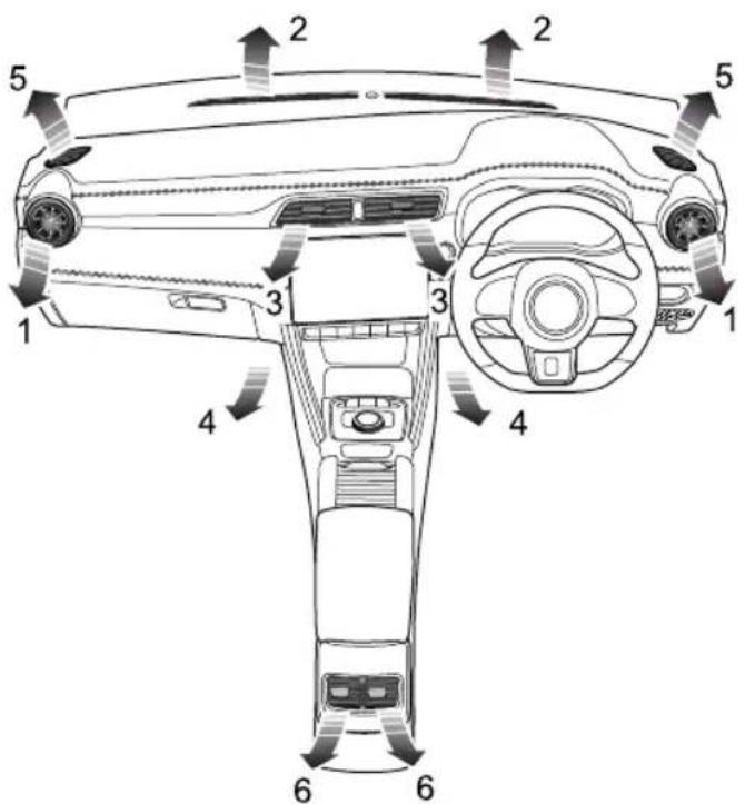
text_image
Technical diagram of a car interior with numbered components and directional arrows indicating motion or flow.I SideVents
2Windscreen/DefrostVents
3CentreVent
4FrontFootwellV ents
5FrontSideWindowV ents
6CentreConsoleVents
AIRCONDITIONINGANDAUDIOSYSTEMS
Theairconditioningsystemisusedtoadjustthe temperature,speed,humidityandcleanlinessoftheairin thecar.Freshairisdrawninthroughtheairintakegrille atthebaseofthefrontwindscreenandA/Cfilter.
Alwayskeeptheairintakegrilleclearofobstructionssuch asleaves,snoworice.
A/CFilter
TheA/Cfilterisusedtofilterair .T oremainfullyeffective, thefiltershouldbereplacedattherecommendedservice interval.
Vents
CentreVents
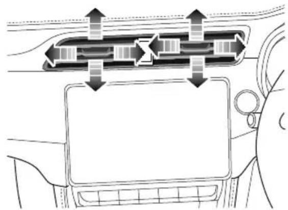
natural_image
Diagram of a car interior showing airflow or traffic flow between two vehicle sections (no text or symbols)Slidethebuttoninthecentreofthelouvrestotheleftor righttoopenorclosethevent.
T ogglethebuttonatthecentreofeachventupanddown, leftandrighttoregulatetheairdirection.
AIRCONDITIONINGANDAUDIOSYSTEMS
SideVents
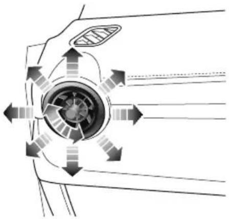
natural_image
Diagram of airflow or mechanical components around a central circular component, showing directional arrows (no text or symbols)Rotatethecentrethumb-wheelclockwiseor anti-clockwisetoopenorclosethevent.
T ogglethecentrethumb-wheelup,down,leftorrightto adjusttheairdirection.
CentreConsoleVents
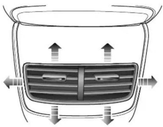
natural_image
Top-down view of a car's front grille and dashboard with directional arrows indicating airflow or movement (no text or symbols)Slidethebuttoninthecentreofthelouvrestotheleftor righttoopenorclosethevent.
T ogglethebuttonatthecentreofeachventupanddown, leftandrighttoregulatetheairdirection.
AIRCONDITIONINGANDAUDIOSYSTEMS
A/CControlPanel
ControlPanel
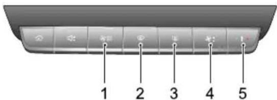
text_image
1 2 3 4 5IA/CControlShortcut
2Defrost/DemistButton
3HeatedRearWindowButton
4BlowerSpeedControlButton
5T emperatureControlButton
A/CControlShortcut

ShortpresstheA/Ccontrolshortcuttodisplay ditioninginterfaceontheinfotainmentscreen.
LongpresstheA/Ccontrolshortcuttoswitchthesystem on, allfunctionswillreverttothestatebeforeshutdown. Longpressagaintoswitchoff.
Defrost/Demist

PressDefrost/DemistButtononthecontrol panel,theindicatorsonthebuttonanddisplayilluminate, theA/Ccoolingandexternalcirculationfunctionsare switchedon,andthesystementersthedefrost/demist functiontoclearthewindshieldandsidewindows.
Pressagaintoswitchoff. The indicator will go off and the system will return to the previous state
Whilstthedefrost/demistisselected,operatetheA/C on/offbuttontoturnthecompressoron/off;operate theairrecirculationbuttontoswitchbetweeninternal recirculationandexternalcirculation;operationofeither
AIRCONDITIONINGANDAUDIOSYSTEMS
of these functions will not affect the defrost/demist function; operation of any other air distribution modes will quit defrost/demist.
HeatedRearWindow

Theheatingelementsontheinsideoftherear windowareeasilydamaged.DONOTscrape orscratchtheinsideoftheglass.DONOT sticklabelsovertheheatingelements.

PresstheHeatedRearWindowButtonto
switchthefunctiononoroff. Thebuttonindicator illuminateswhenthefunctionison, andisextinguished whenthefunctionisoff. Theheatedrearwindowfeatures atimerfunctionandwillautomaticallyswitchoffaftera presettime. T ocontinuetousetheheatedrearwindow, operatethebuttonagain.
BlowerSpeedControlButton

Presstheblowerspeedcontrolbuttonupward
ordownwardtoregulatetheblowerspeed.
T emperatureControlButton
Pressthetemperaturecontrolbuttonupward
ordownwardtoregulatethetemperatureoftheair suppliedbythevents.
AIRCONDITIONINGANDAUDIOSYSTEMS
A/CControllInterface
ControllInterface-ConnectedCar
*
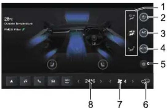
text_image
26°C Outside Temperature PM2 & Filter 1 2 3 4 5 8 7 6AirDistributionModeControl
SystemOn/Off
Cooling On/Off
AutoMode
A/Setting
AirCirculationMode
BloweSpeedControl
Bemperature Control
AIRCONDITIONINGANDAUDIOSYSTEMS
ControlInterface-NonConnectedCar
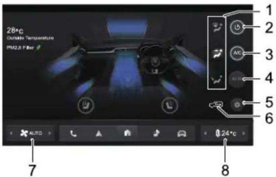
text_image
28°C Curable Temperature PM2.5 Filter 1 2 3 4 5 6 7 8 AUTO 0 24°CAiDistributionModeControl
SystemOn/Off
Cooling On/Off
AutoMode
A/Setting
AirCirculationMode
BloweSpeedControl
Bemperature Control
AIRCONDITIONINGANDAUDIOSYSTEMS
T emperatureControl
Touch the temperature control touch button to regulate the temperature of the air supplied by the events.
CoolingOn/Off
TouchthecoolingOn/Offtouchbuttontooperatethe coolingfunction.
Note: Asmallamountofwatermayremainintheair conditionerafterusage, this may produce a peculiar smell. If this is a particular issue, it is recommended to switch off the cooling function and run the blower for awhile.
AutoMode
Setthetargettemperaturerequiredandthenpressthe AUTOtouchbuttontoenabletheautomodefunction.In automode,theairdistributionmode,blowerspeedand otherfunctionsareautomaticallyadjustedtoreachand maintaintherequiredtemperature.
Manuallyadjusttheairdistributionmodeorblowerspeed toexitautomode.InthiscasetheAUTOindicatorwill extinguish.
Note: To ensure the automode operates efficiently, all windows and the sunroof must be closed and their inlet grille must be clear of obstructions. In addition, the A/CAuto controls sensor should not be recovered.
SystemOn/Off
TouchthesystemOn/Offtouchbuttontoswitchthe systemonoroff.
BlowerSpeedControl
Touchtheblowerspeedcontroltouchbuttontoregulate theblowerspeed.
AirDistributionMode
Select the corresponding Air Distribution Mode T ouch Button as required to regulate the air distribution mode.
| T ouchButtonOnAir | DistributionMode |
| T o'Face' | |
| T o'Face+Feet' |
AIRCONDITIONINGANDAUDIOSYSTEMS
| T ouchButtonOnAir | DistributionMode |
 | T o'Feet' |
 | T o'Feet+Windscreen' |
 | T o'windscreen' |
Note: Theairdistributionmodecanalsobeswitched bytouchingtheairoutletareaofthecontrolinterface.
T o'Face'.Directsairflowtothesideandcentrevents.
T o'Face+Feet'.Directsairtofootwell,sideandcentre vents.
T o'Feet'.Directsairtofootwellvents.
Note: In this mode, asmall amount of airflow will be directed to the side, front sidewindow and front wind screen vents.
T o'Feet+Windscreen'.Directsairtothefootwell,front windscreenandfrontsidewindowvents.
Note: In this mode, as small amount of airflow will be directed to the side events.
T o'windscreen'.Directsairtothewindscreen/defrostand frontsidewindowvents.
Note: In this mode, as small amount of airflow will be directed to the beside events.
AirCirculationMode
Touchtheairrecirculationmodetouchbuttontoswitch betweenairrecirculationmodes.
During internal recirculation, the air
conditioningsystemcirculatestheairinsidethecarto meettherequirementsofrapidcoolingorheating,andat thesametime,itcanpreventtheentryoftrafficfumes.
During the external circulation, air
conditioningsystemdrawsairfromoutsidethevehicleto ensurefreshairentersthevehicle.
AIRCONDITIONINGANDAUDIOSYSTEMS
During automatic circulation, the air
conditioningsystemcanautomaticallyadjusttheinternal recirculationorexternalcirculationaccordingtothe situation.
Note:Leavingthesystemininternalrecirculation modecancausethewindscreentomist. If this happens, turnonthedefrost/demistmode.
AIRCONDITIONINGANDAUDIOSYSTEMS
InfotainmentSystem \*
ImportantSafetyInformation
- Donotattempttofit, repairormodify the entertainmentsystembyyourself, there are high-voltagecomponentsinthedevice, which may cause electricshock. For internal inspection, adjustmentorrepair, please consultalocalMG AuthorisedRepairer.
- Donotallowthisentertainmentandnavigation systemtocomeintocontactwithliquidliquids orforeignobjectsenteintothisentertainmentand navigationsystempleaseparkyourvehicleinasafe placemmediatelywitchoffpowerandontact alocAMGAuthorisedRepairer.Doncasethe entertainmentandnavigationsysteminthiscondition because doing may result in fireelectricshock or otherfailure.
• If you notices smoke, abnormal noises or odours from the entertainment system, any other abnormalities on the screens, switch power off immediately and contact a local MAuthorised Repaire for service.
Using this entertainment system in this condition may result in permanent damage of the system.
•OperationofthenavigationorvideofunctionsofthesystemisprohibitedwhilsthevehicleismotionMG Motoracceptsnoresponsibilityforanyconsequences causedbythisoperation.Pleaseparkyourvehiclein asafelocationselectParkandapplytheparkingbrake beforemakinghenecessaryadjustmentsorwatching Video.
•Particular high or particularly low temperatures will interfere with normal operation. If the vehicle has not been used, parked direct sunlight particularly cold conditions, the am a be compared by or cold, in this environment the system may not work properly. Oncethemperature inside the car is back to normal the system will resume normal function if does not resume please contact doca MGA authorised Repairer for assistance.
Excessive entertainment and navigation system without the vehicle being driven or in READY mode and rain the vehicle down voltage battery.
AIRCONDITIONINGANDAUDIOSYSTEMS
- Y ournavigationisonlyaguide,youmustalwaysconsider andfollowthetrafficsigns,anddriveaccordingtoroad conditions;ifyoudeviatefromtherecommendedroute, theentertainmentandnavigationsystemwillchangethe directiveaccordingly.
- When using a mobile phone, keep the antenna of the mobile phone away from the screentoprevent the disruption of videosignal in the form of spots, colored stripes, etc. on the screen.
PrivacyandDataSharing
When using this entertainment system for the first time, you must read the Privacy Policy carefully and make a choice.
Inthesettingsinterfaceoftheentertainmentsystem,you canauthorise/disablethedatasharingserviceatanytime. Plesenotethatoncedisabled,therelevantfunctionswill notbeavailable.
Note: Restoringfactorysettingsorupgradingsoftware may require youtoreauthorisedatasharingservices.
CautionsforUsingScreen
- T oprotectthescreenagainstdamage,besuretotouch thepanelbuttonswithyourfinger(atouchpencanbe usedforspecialcalibration).
- Pleaseprotectthescreenagainstdirectsunlight. Extendedexposuretodirectsunlightwillresultin screenmalfunctionduetohighttemperature.
- Whenthetemperatureisaboveorbelowtheoperating temperaturerange(-30°Cto+85°C), pleasedonotuse theLCDscreen,thescreenmaynotoperatenormally andcouldbedamaged.
- Donotuseexcessiveforcetodraganddroporpress thescreen,damageorscratchingmayoccur.
•T oremovedustfromthescreenorcleanthescreen, pleaseturnthesystemofffirst,andthenwipewitha drysoftcloth.Whenwipingthescreen,takecarenot toscratchthesurface.Donotuseirritativeorabrasive chemicalcleaners.
AIRCONDITIONINGANDAUDIOSYSTEMS
BasicOperations
ControlPanel
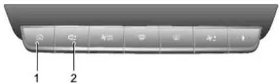
text_image
Diagram of a vehicle rear panel with labeled buttons and indicatorsI(HOME)Button
Shortpresstoreturntothemaininterface ; continue topressforabout10secondstorestartthesystem.
2VolumeAdjustmentButton
MainSystemInterface
PageOne
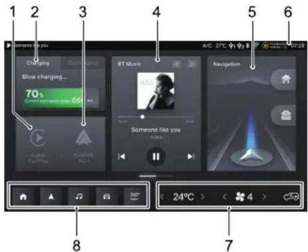
text_image
1 2 3 4 5 6 Changgng Slow charging... 70% Smart ear/night song 66 Apple Carney Aululead Auto BT Music Someone like you Navigation A/C 27°C 91° 01:28 8 < 24°C > 4 7IAppleCarPlay
TouchtoentertheAppleCarPlayinterface.
2EnergyManagement
AIRCONDITIONINGANDAUDIOSYSTEMS
TouchtoentertheEnergyManagementinterface.
3AndroidAuto
TouchtoentertheAndroidAutointerface.
4Radio/Music
TouchtoentertheRadio/Musicinterface.
5Navigation
TouchtoentertheNavigationinterface.RefertoNavigationManualfordetails.
6StatusBar
Displaysignalstrength, timeandotherinformation. Pulldowntoentertheshortcutcontrolpage, here youcansetthescreenbrightness, carcontrol, etc.
7A/CAdjustment
T ouchtoadjusttemperature, blowerspeedandair recirculationmode.
8ShortcutIcons
•T muchtoenterthemainsysteminterface.
- ▲T ouchtoentertheNavigationinterface.
•T ouchtoentertheMusicinterface.
- TouchtoentertheVehicleSettinginterface.
• T ouchtoenterthe360interface.
PageTwo
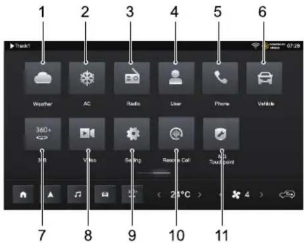
text_image
1 2 3 4 5 6 Track1 Weather AC Radio User Phone Vehicle 360+ Video Setting Rescue Cell GPS Touchpoint 7 8 9 10 11IWeather
AIRCONDITIONINGANDAUDIOSYSTEMS
TouchtoentertheWeatherinterface.RefertoNavigationManualfordetails.
A/C
TouchtoentertheA/Cinterface.Referto“A/C ControllInterface”inthissectionfordetails.
3Radio
TouchtoentertheRadiointerface.
4User
TouchtoentertheUserinterface.RefertoNavigation Manualfordetails.
5Phone
TouchtoentertheBluetoothPhoneinterface.
6Vehicle
TouchtoentertheVehicleSettingsinterface.
360
Touchtoenterthe360aroundviewinterface.Refer to"360AroundViewSystem"sectioninthismanual fordetails.
8Video
TouchtoentertheVideointerface.
9Setting
TouchtoentertheSettinginterface.
10RescueCall
TouchtoentertheRescueCallinterface.RefertoNavigationManualfordetails.
IIMGT ouchpoint
TouchtoentertheMGT ouchpointinterface.
AIRCONDITIONINGANDAUDIOSYSTEMS
PowerOn/Off
PowerOn
PressingtheSTART/STOPSwitchtoselecttheACCor ON/READYpositionwillautomaticallysetthesystemto poweron.
Whenthesystemisturnedon, pressandholdthepower buttononthesystemcontrolpanelforabout 10 seconds, thesystemwillrestartautomatically.
PowerOff
WhensettingtheSTART/STOPswitchtooff,thesystem willcontinuetoworkforabout10minutes,andthen automaticallypoweroff.
Afterthevehicleislocked,thesystemwillpoweroff automatically.
SteeringWheelMulti-FunctionSwitchControls
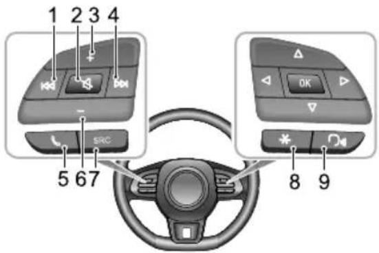
text_image
1 2 3 4 5 67 SRC 8 9Button
Switchtoprevioustrack/station.
Referto 📋 inradio,musicandvideointerfacefor details.
Buttan
Mute/Unmute.
VolumeUpButton
AIRCONDITIONINGANDAUDIOSYSTEMS
4Button
Switchtonexttrack/station.
Refertoin 📄lio, musicandvideointerfacefor details.
5Button
Longpresstohangupifincalling/talkingstate;short presstoanswerandlongpresstorejectifinincoming callstate.
6VolumeDownButton
7SRCAudioSourceSwitchButton
Switchtothenextavailablemediaaudiosource.
8“\*”ShortcutButton
Theuser-defined function of the button can be set in the vehicle settings.
9SpeechRecognitionFunctionButton
Shortpresstoturnonthelocalspeechrecognition function;longpresstoturnonthemobilephone
interconnectionspeechrecognitionfunction;short pressagaintoexitthespeechrecognitionfunction.
Refertonavigationmanualaboutthelocalspeech recognitionfunctionfordetails.
AIRCONDITIONINGANDAUDIOSYSTEMS
VolumeAdjustment
Theaudiovolumecanbeadjustedusingthecontrolpanel, thebuttonsonthesteeringwheelandtheshortcut controlpage. Duringvolumeadjustment, thesystem automaticallypopsupavolumeindicationwindowwhich changessmoothlywiththeadjustmentprocess.
Note: The playback volume of Bluetooth music can be adjusted by the device itself and the Infotainment player.
BluetoothPhone
Instructions
- ConnectiontoallmobilephonesfeaturingBluetooth wirelessstechnologyisnotguaranteed.
- Themobilephoneusedmustbecompatiblewith theInfotainmentsystemsothatallfunctionsofthe connectedBluetoothdevicecanfunctioncorrectly.
- WhenusingBluetoothwirelesstechnology,the entertainmentsystemmaynotoperateallfunctionson themobilephone.
- WhentransmittingvoiceanddataviaBluetooth technology,thestraight-linedistancebetweenthe entertainmentsystemandthemobilephoneshouldhot exceed 10metres.However,theactualtransmission distancemaybeshorterthantheestimateddistance, dependingontheusageenvironment.
- Whentheentertainmentsystemisturnedoff, the Bluetoothconnectionwillbedisconnected.
- DuetoBluetoothwirelessconnection, interruptionor erroroccurringintheprocessoftransmissioninsome extremecases the entertainmentsystem maybeunable tobepairedandconnectedwithhemobilphone.
AIRCONDITIONINGANDAUDIOSYSTEMS
Atthistime, it is recommended to clear the paired devices in the device list on the mobile phone and the entertainment system, and conduct pairing again.
Pleaseconnectabluetoothdevicefirstbeforeattempting touseanyBluetoothphonefunctions,Referto"Bluetooth PairingandConnection"in"Settings"sectionfordetails.
Touchthe[Phone]cardinthemaininterfacetoentertheBluetoothphoneinterface.

text_image
Alan Luckridge 175 2176 09769 Alan Buckridge 178 2176 0969 Alphanso Jenkins 137 3854 8367 Buddy Kuvalis 178 2102 2023 300+ < 24°C > < 4 > Call History Contacts KingmailMakingCall
Callscanbemadeusingthefollowingmethods:
- Callthenumberincallhistory.
- Callthenumberincontacts.
- KeypadInput.
•Directlyonthemobilephone.
EndingCall
Callscanbeendedusingthefollowingmethods:
•T ouch 🔍 tohangup.
•Longpressonthesteeringwheeltohangup.
• Hanguponthemobilephone.
IncomingCall
AnsweranIncomingCall
•T ouchtoansweranincomingcall.
- Shortpressbuttononthesteeringwheeltoanswer anincomingcall.
- Answeranincomingcallonthemobilephone.
RejectanIncomingCall
- T ouch ⚙ torejectanincomingcall.
- Longpress buttononthesteeringwheeltorejectan incomingcall.
- Rejectanincomingcallonthemobilephone.
AIRCONDITIONINGANDAUDIOSYSTEMS
Duringacall
Duringacall,
- T ouchtoenterthePrivateMode; T ouchtorestore theSpeakerMode.
- TouchoswitchbetweenMicrophoneMuteor Enabledfunction.
•T ouch 📄 toenterthekeypadinterface. - T ouchtoaddthirdpartycallsandkeepthecurrent call. When there are twocalls, shortpressbutton on thesteeringwheelortouchthecorrespondingcontact icontoswitchthecalobject(ltcanonlybeusedwhen themobilephonesupportsthree-partycallfunction).
•T ouch 🔒 tocheckthecontacts.
InPrivateMode,youmaycontinuewiththecallusing themobilephone;thespeakersandmicrophoneofthe entertainmentsystemwillbenuteBluetoothremains connected.
Noteltisillegaltooperateamobiletelephonewhilst driving. If you wishtomake, or take acall using your mobilephonedirectly, please ensure you pulloverina
suitablelocationandoperatethemobilephonewhere itissafeandlegaltodoso.
AIRCONDITIONINGANDAUDIOSYSTEMS
Entertainment
PrecautionsforPlayingfromaStorageMedium Mode
- ThesystemsupportsUSBdrivesandBluetoothstorage media.
- If the USB device media is not in use, DONOT leave the device connected. This may result in connection deterioration.
- DonotremoveUSBdevicewhilstmediaisplaying. Failuretofollowtheseinstructionscouldresultin corrupteddata.
- KeeptheUSBportdryandfreefromdebris.Theport willbecomeunusableifitisblocked.
- Duetodifferencesinthecompressionratioandbit rateofthemultimediaformatsdownloadedfromthe Internetandotherfactors,theactualsituationofthe decodingresultshallprevail.
Connecting/DisconnectingaUSBStorage
Device
InsertingaUSBStorageDevice
ConnectaUSBdevicetotheUSBportforconnection.
RemovingaUSBStorageDevice
Checkandconfirmthatthereisnodatabeingaccessed, thenpullouttheUSBstoragedevice.
Note: If any datalossor breach occurs whilst the USB storage device is inserted or being used, it will generally be unrecoverable. MGMotor accepts no responsibility for any datalossor breach.
Note/Storage via unidentifiable.
Note: The Infotainmentsystemmaynotachieveits optimum performance when usingsome USB storage devices.
Note: Using a USB huborextension cable may result in the USB device not being recognised.
AIRCONDITIONINGANDAUDIOSYSTEMS
Radio
Touch[Radio]inthemaininterfacetoentertheradio interface.
T olistentobroadcastsondifferentbands,touch[DAB], [FM]or[AM]ontherightofthescreentoswitchbetween radiobandsandDAB.PressingtheSRCbuttoncanalso switchbetweenthedifferentradiobands.
DAB
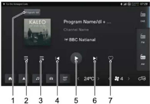
text_image
For the Dated Cada Program Name/dl + ... Channel Name BBC National 1 2 3 4 5 6 7 24°C 4 07:28 DAR FM AMI Stationlistofthecurrenttransmitterarea
2Listofvalidstations
3Listoffavoritestations
Shoppressswitchthepreviousalradio station;Longpresstoswitchchannels.
5Pause/playthecurrentstation
6Shortpresstoswitchtothenextvalidradiostation; Longpresstoswitchchannels.
7AddaStationto/RemoveaStationfromFavorites
AIRCONDITIONINGANDAUDIOSYSTEMS
FM/AM
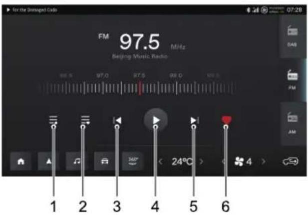
text_image
For the Disordered Code FM 97.5 MHz Beijing Music Radio 1 2 3 4 5 6 24°C 4I Listofvalidstations
2Listoffavoritestations
3Shortpresstoswitchtothepreviousvalid radiostation;longpresstoquicklyadjustthe frequency/amplitudemodulation.
4Pause/playthecurrentstation
5Shortpresstoswitchtothenextvalidradiostation; longpresstoquicklyadjustthefrequency/amplitude modulation.
6AddaStationto/RemoveaStationfromFavorites
Drag ☐ tofinelyadjustthefrequency/amplitude modulation.
AIRCONDITIONINGANDAUDIOSYSTEMS
Music
TouchtheRadio/Musicareainthemaininterfaceorthe icontoenterthemusicinterface.
Touch[BTmusic]/[amazonmusic]/[USBmusic]on therightofthescreentoenterthecorrespondingmusic interface.PressingtheSRCbuttoncanalsoswitch betweenthedifferentsoundsource.
Refertonavigationmanualabouttheamazonmusicfor details.
BluetoothMusic
PleaseconnectaBluetoothdevicefirstbeforeplaying Bluetoothmusic.Referto"BluetoothPairingand Connection"in"Settings"sectionfordetails.

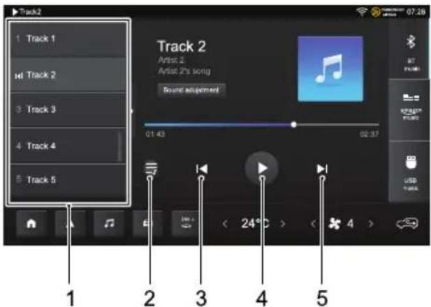
text_image
Track2 1 Track 1 H Track 2 3 Track 3 4 Track 4 5 Track 5 Track 2 Artist 2 Artist 2's song Sound adjustment 01:43 02:37 1 2 3 4 5 < 24°C > < 4 > 07:28 87 F1000 RGB/RGB USB T-6000Tl rackList
Opening/ClosingTrackList
PreviousT rack
Play/Pause
NextTrack
Note: Somemobilephonesorbluetoothdevicesmay notsupportsynchronizedtracklists, and therelevant information will not be displayed in the playlist bar.
AIRCONDITIONINGANDAUDIOSYSTEMS
USBMusic
InsertaUSBstoragedeviceintotheUSBport,andthe systemautomaticallyloadsthemusicfromthestorage device.
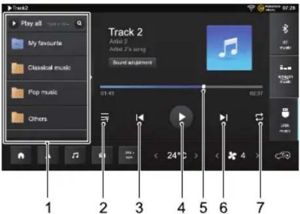
text_image
Track2 Play all My favourite Classical music Pop music Others Track 2 Artist 2 Artist 2's song Sound adjustment 01:43 02:37 1 2 3 4 5 6 7TrackList
Touch to search song according to name.
Touch display the currentyrics.
PreviousTrack
Play/Pause
Draghoprogresbatanplaybackpoint.
NextTrack
Touchswitchbetweensinglecyclemodelistcycle modeandrandomplaymode.
AIRCONDITIONINGANDAUDIOSYSTEMS
Video
InsertaUSBstoragedeviceintotheUSBport,touch [Video]inthemaininterfacetoenterthevideoplayback interface.
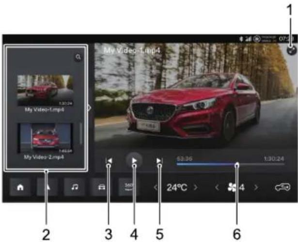
text_image
My Video-Lmp4 My Video-2.mp4 My Video-Lmp4 63.36 1:30:24 24°C > 4 6IT ouchtoswitchtofullscreen playbackmode.
2PlayList
T ouchtosearchforvideoaccordingtoitsname.
3Shortpresstoswitchtothepreviousvideo;longpress tofastrewind.
4Play/Pause
5Shortpresstoswitchtothenextvideo;longpressto fastforward.
6Dragtheprogressbartoanyplaybackpoint.
AIRCONDITIONINGANDAUDIOSYSTEMS
Vehicle-MobilePhoneInterconnection
Note: Only the USB portonthedriver's side can support vehicle-mobile phone interconnection.
Note: Duetothedifferencesofmobilephonemodels andsystemversions, somemobilephonesmaynotbe abletousethevehicle-mobilephoneinterconnection functionnormally.
AppleCarPlay
AppleCarPlayenablesinformationinteractionbetweenthe mobilephoneandtheon-boardentertainmentsystem, includingmap,music,telephone,voicerecognitionandso on.
ConnectionMethod
I Confirm that youriPhone has the Carplay function and that it is turned on.
2Connectthemobilephonetotheentertainment systemmainframeusinganapprovedUSBcable.
3Inthemaininterface,touch[AppleCarPlay]areato entertheAppleCarPlayinterface.
4Afterthevehicleandmobilephonearesuccessfully connected,youcanoperatetheiPhoneusingthe entertainmentsystemscreen.
5PresstheHOMEbuttononthecontrolpaneltoreturn tothemainsysteminterface.
AndroidAuto
AndroidAutoenablesinformationinteractionbetweenthe androidmobilephoneandtheon-boardentertainment system,includingmap,music,telephone,voicecommands andsoon.
EnsuretheAndroidAutosoftwareisdownloadedtoyour phoneusinganAPPfromyourregionalAPPsupplier. Ensurethatthefunctionisenabled.
ConnectionMethod
I Connectthemobilephonetotheentertainment systemusinganapprovedUSBcable.
2Inthemaininterface,touchthe(AndroidAuto]area toentertheAndroidAutointerface
AIRCONDITIONINGANDAUDIOSYSTEMS
3Operateaccordingtotheinterfaceprompts,youcan thenusethephonefunctionsoncetheconnectionis successful.
4PresstheHOMEbuttononthecontrolpaneltoreturn tothemainsysteminterface.
EnergyManagement
TouchtheEnergyManagementareainthemaininterface toentertheenergymanagementinterface.Y oucanview thecurrentelectricityinformation,chargingsettings,etc.
MGT ouchpoint
T ouch[MGT ouchpoint]inthemaininterfacetoenter theMaintenanceinterface.Y oucanviewthedealer information.
VehicleSetting
Touch[vehicle]inthemaininterfaceortheicontoenter the vehicle setting interface. Our the Pilot, lights, etc., and can also view the vehicle information and maintenance status.
AIRCONDITIONINGANDAUDIOSYSTEMS
Setting
Touch[Setting]inthemaininterfacetoenterthesettings interface.Y oucansetgeneralsettings,connectionmode andflowmanagement.
General
Inthesettingsinterface,touch[General]toenterthe generalsettingsinterfacetosetthescreenbrightness,time,etc.
BluetoothPairingandConnection
ThestepsofBluetoothpairingandconnectionareas follows:
- Touch[Bluetooth]inthesettingsinterfacetoenterthe bluetoothinterface, enabletheBluetoothfunction.
Localname:displaysthenameofthevehicle,youcan customizethename,thenameofthevehiclehotspot willbeupdatedsynchronouslyaftermodification.
•Theon-boardmainframewillactivelysearchfornearby Bluetoothdevicesthatcanbeconnectedandshow themin[OtherDevices],youcanalsosearchforthe
vehicledeviceusingthephonetopair,afterthepairing iscompleted,theBluetoothicon willshowinthe statusbar.Ifthepairingfails,pleaserepeattheabove steps.
The devices already paired and connected are displayed in the [Connected Currently] directory, only one Bluetooth device can be connected to this system.
IntheBluetoothConnectioninterface,youcanchoose whetherornottosyncronizecallhistoryandcontacts, disconnectthecurrentlyconnecteddevice,andpairwith otherdevicesin[Pairinghistory]or[Otherdevices] accordingtoyourrequirements.
WiFiConnection
WIFIconnectionstepsareasfollows:
- Inthesettingsinterface,touch[Wirelessnetwork], entertheWIFIconnectioninterface,andturnontheWIFIswitch.
- SelecttheWIFIwithwhichyouwanttoconnectinthe [ChoosetheNetwork]columntoconnect,ortouch [AddWiFi]toconnecttoahiddenWIFIbyentering theWIFIname,securitytypeorpassword.
AIRCONDITIONINGANDAUDIOSYSTEMS
Note: Foryourinformationsecurity, itis recommended to select a WIFI connection with high security level of WPA2.
HotspotConnection
Inthesettingsinterface,touch[VehicleHotspot],enterthe vehiclehotspotinterface,andturnontheVehicleHotspot switch.
- Vehiclename:displaysthenameofthisvehicle,youcan customizethename,thevehiclenameonthevehicle Bluetoothwillalsobeupdatesynchronouslyafter modification.
- Hotspotpasscode:youcancustomizethevehicle hotspotpassword,thepasswordlengthshoulde greaterthan8characters.
- Hotspotnetworkfrequencyband:youcanchoose 2.4GHzor5GHz24GHzsupportsmoredevices connectedtheehichotspobuatayo generateinterference,5GHzistheopposite,youcan setaccordingtoyourneeds.
- DeviceConnecteddisplaysthenumberofdevices connected vehiclehotspanddevice information.
TrafficManagement
Inthesettingsinterface,touch[Datatrafficmanagement] toenterthetrafficmanagementinterface,youcanturnthe onlinenetworkswitchonoroffandviewthedatausage.
Voice
Inthesettingsinterface,touch[Voice]toenterthevoice settinginterfacetoschevoicebroadcastlanguage, greetings,etc.
Volumesettings
Inthesettingsinterface,touch[Volumesettings]toenter thevolumesettinginterfaceosetthesystemsound, chime,etc.
AIRCONDITIONINGANDAUDIOSYSTEMS
System
Inthesettingsinterface,touch[System]toenterthe systemsettinginterface.Y oucanviewthesoftware versionorupgradetheapplicationsoftware.
Touch[Upgrade]toentertheupgradeinterfaceandselect [DetectNewVersions].Ifthesystemdetectsanew version,youcandownloadandinstallthenewsoftware versionaccordingtotheinterfaceprompt.
Note: For software version, map and voice upgrade related functions, please consult an MGA authorised Repairer.
Activation
Inthesettingsinterface,touch[Activation]toenterthe activationinterface.Iftheactivationprocesshasnotbeen completed,youcanactivateitagainhere.
Privacypolicy
Inthesettingsinterface,touch[Privacypolicy]toenterthe privacypolicyinterface,whereyoucanviewtheprivacy policyandchoosewhethertoagreewithitornot.
UserManual
Inthesettingsinterface,touch[UserManual]toenterthe usermanualinterface.Y oucanviewtheusermanualand entertainmentmanual.
Seats&Restraints
112Seats
117SeatBelts
128 AirbagSupplementaryRestraint System
137ChildRestraints
SEATS&RESTRAINTS
Seats
Overview

To avoid personal injuries dueto the loss of control, DONOT adjust these at while the carismoving.
Anidealpositionoftheseatshouldmakesureyourdriving positioniscomfortable,whichallowsyoutoholdthe steeringwheelwithyourarmsandlegsslightlybentand controlalltheequipment.Makesureyourdrivingposition iscomfortableandenablesyoutomaintainfullcontrol ofthevehicle.T akecarewhenadjustingtheheightof frontseats-thefeetoftherearpassengercouldbecome trappedwhenteseatislowered.
Donotinclinethefront-seatbackrestexcessively. Optimumbenefitisobtainedfromtheseatbeltwiththe backrestanglesettoapproximately25°fromtheupright (vertical). Thedriverandfrontpassengerseatsshould bepositionedasfarrearwardaspractical. A properly adjustedseathelpsreducetheriskofinjuryfromsitting tooclosetoaninflatingairbag.
HeadRestraints

Adjusttheheightoftheheadrestraintsothat thetopofitisinlinewiththetopofthe occupant'shead. Thislocationmayreduce theriskofheadandneckinjuriesintheevent ofacollision.DONOTadjustorremovethe headrestraintswhilethecarismoving.

DONOThanganythingonanyheadrestraint orheadrestraintrod.
Theheadrestraintisdesignedtopreventrearward movementoftheheadintheeventofacollisionor emergencybraking,therebyreducingtheriskofheadand neckinjuries.
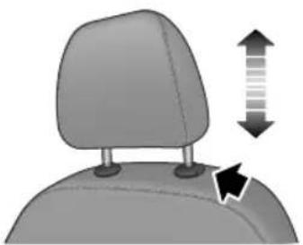
natural_image
3D illustration of a car headrest with directional arrows indicating movement or change (no text or symbols)Whenadjustingtheheadrestraintsfromalowtohigh position,pulltheheadrestraintdirectlyupward,andgently pressitdownwardafteritreachesthedesiredposition to makesurethatitislockedinposition.T oremovethe headrestraint,pressandholdtheguidesleevebutton(as indicatedbythearrow)ontheleftoftheheadrestraint, thenpulltheheadrestraintupwardtoremoveit.
Whenadjustingtheheadrestraintsfromahightolow position,presstheguidesleevebutton(asindicatedbythe arrow)ontheleftoftheheadrestraint,andpressthehead restraintdownward;releasethebuttonafteritreaches thedesiredposition,andgentlypresstheheadrestraint downwardtomakesurethatitislockedinposition.
FrontSeats
ManualSeat
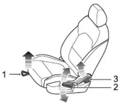
text_image
1 2 3SEATS&RESTRAINTS
•Forward/BackwardAdjustment
Liftthelever(I)undertheseatcushion, slidetheseat intoanappropriatepositionandreleasethelever.Make surethattheseatislockedinplace.
• CushionHeightAdjustment
Liftthelever(2)repeatedlytoraisetheseatcushion, andpresstheleverdownwardtolowertheseat cushion.
- BackrestAdjustment
Liftthelever(3),adjustthebackrestuntilmovesinto asatisfiableposition,andputdownthelever.
PowerSeat *
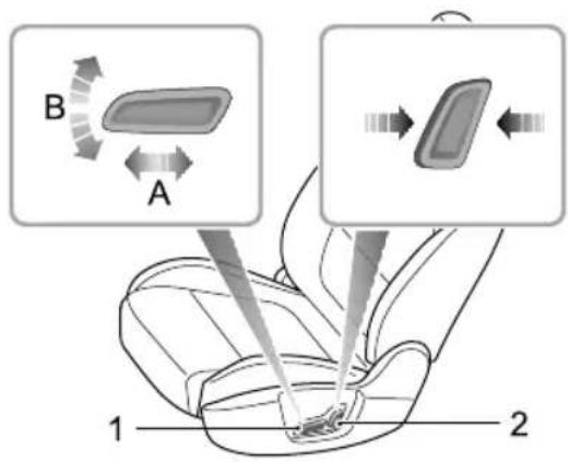
text_image
B A 1 2•Forward/RearwardAdjustment
Pushtheswitch(I)forwardorbackward(A)tomove theseatforward/backward.
• CushionHeightAdjustment
Pulltheswitch(1)upwardorpushdownward(B)to raiseorlowertheseatcushion.
- BackrestAdjustment
Movetheswitch(2)forward/backwardtoadjustthe backrestuntilreachesthedesiredangle.
RearSeats
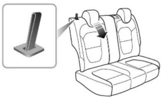
natural_image
Line drawing of a car seat with a pull-up cable and a magnified inset showing the side view (no text or symbols)T oincreaseluggagespace,therearseatbackrestcanbe fullyfoldedforward.Whenfoldingthebackrest,firstfully lower(orremove)alltherearseatheadrestraints,and thenpullupthebackrestunlockstrapsonbothsides respectivelyandfoldtheseatbackrestsforward.
T oreturnthebackresttoanuprightposition,raisethe rearseatbackrest.Whenthedesireduprightpositionis
SEATS&RESTRAINTS
reached, a 'click' will be heard. Ensure the backrest is locked in position.
Note: Whentheheadrestraintoftherearseatis notfullyloweredorthebackrestofthefrontseatis inclinedbackwardexcessively, thefoldingoftherear seatisverylikelytodamagethebackofthefrontseat, smallstoragecompartmentorheadrestraintofthe rearseat.
Note: When returning therearseatbackrest to the desired position, makesure that therearseatbelt is not trapped.
FrontSeatHeating \*

Ifbareskinisincontactwiththeheatedseats forexcessiveperiodsoftime,itmaycause burns.
Theseatcushionandbackrestareprovidedwithheating elements.AfterthevehicleissettoREAD Ymode,access theairconditioningcontrolinterfaceandpresstheseat heatingswitchtocontroltheheatingfunctionofthe correspondingseat.
Whenpressingaseatheaterswitch, the corresponding seatwillbecomewarm. Presstheswitchagaintostop the heatingfunction. Whenteseatheatingfunctionis activated, the operating indicatorintheswitchilluminates. Whenthetemperaturereachesapproximate42°C, the heatingfunctionwillbedeactivatedautomatically.
IMPORTANT
DONO Tovethaateseatwithblankets, cushionsorothinsulationtypeobjectors materials.
the temperaturaseache42° and continuesgettinghotterwhenusingtheseatheating system,pleaseturrofftheseatheatingandcontact anMGAuthorisedRepairer.
• Overuseofthedriver'sheatedseatmaycause drowsinessandcouldaffectsafety.
SEATS&RESTRAINTS
SeatBelts

It is important that all seat belts are worn correctly. Always check that all passengers are wearing seat belts. DONOT carry passenger that are unable to wear correctly positioned seat belts. Wearing seat belts incorrectly may cause serious injury over death in the event of a collision.

Airbags cannot replace seatbelts. Airbags canonly provide extrasupport when triggered by accident will trigger airbag whether airbags are triggered not seabels can reduce the risk of serious injury or death in accidents. Therefore, seatbelts must beworn properly.

NEVERfastereabelvilsdriving, seriousinjuryordeathmayoccurinthecase ofanaccidentoremergencybraking.

This vehicle equipped with seat belt warning
lamptoremindyoutofastenyourseatbelt.
Duringdrivingseabeltsmustbefastened, thisbecause:
You came over predict if you will be involved in collision accident and how serious it maybe.
Imanyases of collision accident passenger with seatbelts properly fastened are well-protected, while passengers with seatbelts not fastened suffer from serious injury overvendeath.
Therefore, all passengers must wear seat belts correctly, evendurings short-distance journeys.
ProtectionProvidedbySeatBelts

Iisoequalimportanceforpassengersinthe rearseattofastentheirseatbeltscorrectly. Otherwise, passengerswithseatbeltsnot correctlyfastenedwillbethrownforwardin accidents,andvillendangethemselvesas wellasthedriverandotherpassengers.
SEATS&RESTRAINTS
Whenthevehicleisinmotion,thetravellingspeedofthe occupantsisidenticaltothatofthevehicle.
Intheeventofa'headoncollision'oremergencybraking, thevehiclemaystop,buttheoccupantswillcarryon travellinguntiltheycomeintocontactwithastationary object.Thisobjectmaybethesteeringwheel,dashboard, windscreenorfrontseats.
Acorrectlyfastenedseatbeltwilleliminatethisriskof injury. Whentheseatbeltisworncorrectly, itwilllock automaticallyincollisionaccidentsoremergencybraking toreduceyourspeedtogetherwiththevehicle, soas topreventtheout-of-controlmovementwhichmaycause seriousinjurytodriverandpassengers.
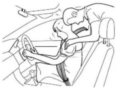
natural_image
Line drawing of a person in a car seatbelt being assisted by another person (no text or symbols)SEATS&RESTRAINTS
WearingSeatBelts

Incorrectlywornseatbeltscouldcauseinjury ordeathintheeventofanaccident.

Seatbeltsaredesignedforoneperson,DO NOTshareseatbelts.

DONOTwrapaseatbeltaroundwhen holdingababyorchildinyourarms.

Removeanyheavycoatsorclothingwhen wearingaseatbelt,failuretodosocanaffect protectionprovidedbytheseatbelt.

Seatbeltsshouldnotbewrappedaround hardorsharpobjectssuchaspens, spectacles orkeys.

Seatbeltscannotfunctioncorrectlywhenthe seatsarereclinedexcessively.DONOTdrive whentheseatsareexcessivelyreclined.
Theseatbeltsfittedtoyourvehiclearedesignedforuse bynormalsizedadults. Thispartoftheliteraturerefersto adultuse.
Allseatbeltsare3pointlap-diagonalbelts.
Inordertomaintaineffectiveprotection, thepassengers mustsitinthecorrectorientation, feetplacedonthefloor infrontofthem, withanuprightbody(noexcessiverecline) andtheseatbeltcorrectlyfastened.
SEATS&RESTRAINTS
FasteningSeatBelts
Please follow the instructions below to fast these seat belts correctly.
I Adjusttheseatcorrectly.
2Holdthemetaltab, pulltheseatbeltoutsteadilyover theshoulderandacrossyourchest. Ensurethereisno twistonthebelt.
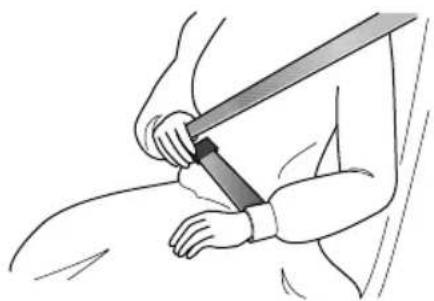
natural_image
Illustration of a person using a bandage to lift a sword (no text or symbols present)3Insertthemetaltabintothebuckleuntilyouheara 'click', this indicates these at belt is securely locked.
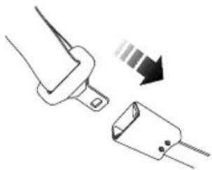
natural_image
Diagram showing a connector with a downward arrow indicating compression or dislocation (no text or symbols present)4Removeanyslacknessinthebeltbypullinguponthe diagonalsectionofthebelt.
5T oreleasetheseatbelt, presstheredbuttononthe buckle. Theseatbeltwillretractautomaticallytoits originalplace.
IMPORTANT
•Alwaysensuretheseatbeltwillnotbecometrapped inthedooraperturewhenclosingthedoor ,damage willoccur.
- Pullingtheseatbeltouttooquicklymaycauseit tolock.Inthiscase,allowtheseatbelttoretract slightlyandthenpullitacrossyourbodyslowly.
•Ifitisdifficulttopulltheseatbeltout,itmaybedue totwistedwebbing.Ifthisisthecase,fullyextract theseatbelt,removethetwist,allowtheseatbelt toretractslowly.
- Whenusingtherearseatbeltspleaseensurethey arefullyretractedintothecorrectpositiontoavoid jammingintherearseatcatches.Eveniftheseat beltistwisted,itisstillrequiredtobewornduring driving,butthetwistedpartoftheseatbeltshould notcontactthepassengWhenthishappens, pleasegotoanMGAuthorisedRepairerforrepair .
CorrectRoutingoftheSeatBelts

Ensuretheseatbeltiscorrectlypositionedon thebody,nevercrosstheneckorabdomen, neverpasstheseatbeltbehindthebackor underthearms.
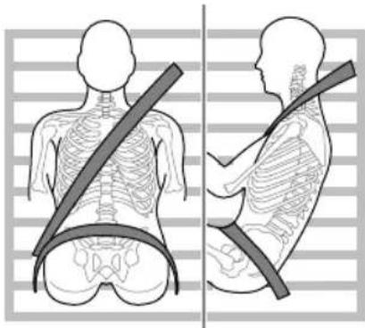
natural_image
Side-by-side illustrations of human torso and neck showing skeletal contours and a belt (no text or symbols)Whenwearingseatbelts,thelapbeltsectionsshouldbe positionedaslowaspossibleacrossyouhipsneveracross theabdomen.Intheeventofacollision,thelapbeltcan applyaforceonthehipsandreducethepossibilityofyou
SEATS&RESTRAINTS
slippingunderthelapbelt. If you slip under the lap belt, the belt will apply force your abdomen, which may cause serious or fatal injuries. Thediagonal section of the belt should cross them middle of the shoulder and the chest. In the event of emergency braking or collision, the diagonal section of the belt will be locked.
To ensure that these seat belts always provide maximum protection, ensure the belt is flat, not loose and contacts the body.
SeatBeltsUseduringPregnancy
Wearingcorrectlypositionedseatbeltswillprovide protectionforbothmotherandunbornchildintheevent ofacollisionoremergencybraking.
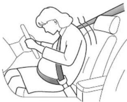
natural_image
Illustration of a person sitting in a car seat, wearing a seatbelt and using a device (no text or symbols visible)Thediagonalsectionoftheseatbeltshouldpassacross thechestasnormal,thelapsectionofthebeltshouldpass belowthebelly,lowandsnugonthehipbones.NEVER positionthebeltonorabovethebelly.
Please consult your physician for further details.
SeatBeltsandDisabilities
Itisalegalrequirementthatallooccupantswearseatbelts, thisincludepeoplewithdisabilities.
Depending upon the disability, consult your physician for further details.
SEATS&RESTRAINTS
ChildrenandSeatBelts

Properprotectionmeasuresmustbetaken forchildrenduringdriving.
Forsafetyreasons, children must travel in a child restraint device fixed to there are seat.
Infants

Only recommended child restraint suitable for the age, height and weight of the child should be used.

NEVERcarryachildorinfantwithyourarms duringdriving. Whencollisionaccidents occur, theweightofthechildwillproduce sogreatofaforcethatyouwillnotbeable toholdontothechild. Thechildwillbe thrownforwardandsufferseriousinjuryor evendeath.
Theseatbeltsfittedtoyourvehiclearedesignedforadults, theyarenotsuitableforchildren.Intheeventofan accidentorcollisionthechildrenarenotsecure,itcould causedeathorseriousinjury.
InfantsMUSTuseasuitablechildrestraintdevice.Please consultthechildseatmanufacturer'sguidelineswhen selectingthecorrectseFollowthemanufacturer's instructioninstallationPleaseRefChild Restraints"inthischapterformoredetails.
OlderChildren

NEVERshareaseatbeltamongstchildren. Intheeventofanaccidentorcollision, the childrenarenotsecure.Itcouldcausedeath orseriousinjury.
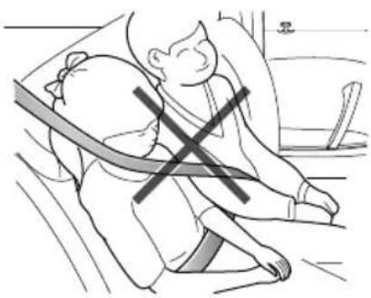
natural_image
Illustration of a person sitting on the floor with a cross symbol indicating pressure or stress (no text or symbols present)SEATS&RESTRAINTS
Aschildrengrowandbecomeolder/largeritwillgettothe stagewhentheynolongerrequirechildseatrestraints.At thispointtheywillrequireuseofthevehiclestandardseat belt.Pleaseensuretheseatbeltiscorrectlypositionedon thebodyofthechild.
When fastening a seat belt for a child always check it for correct positioning. Adjust the height of these seat belt to ensure the shoulder belt is kept away from the child's face and neck. Position the lap belt acrosst the hips as low as possible, and tighten adequately. Correct positioning means that these seat belt can pass the applied forceto the strongest part of the child's body in accidents.
If the shoulder belt to oocloseto the child's face or neck, it may be necessary to use a child boost or cushion (always ensure that it meets any relevant laws or standards).
SeatBeltPre-tensioners

Theseatbeltpre-tensionerswillonly beactivatedonceandthenMUST BEREPLACED.Failuretoreplacethe pre-tensionerswillreducetheefficiencyof thevehicle'srestraintsystem.

If the pre-tensioners have been activated, the seat belt will still function as restraints, and must beworn in the event that the vehicle remains in drivable condition. These at beltpre-tensioners should bere placed at the earliest opportunity by an MGA authorised Repairer.
The vehicle is fitted with seat belt pre-tensioner. These are designed to tract the land or on conjunction with their bag, however, a collision they are designed to retract these seat belt and secure the occupant in theseat.
Theirbagarninlighothinstrumentpackwill aletberivemnalfunctionseabelt
pretensioners.(see 'WarningLightsandIndicators' in the 'InstrumentsandControls' chapter).
Theseatbeltpre-tensionerscanonlybeactivatedonce. Afteractivationtheymustbereplaced. Thismayalso involvereplacementofotherSRScomponents.Please referto'ReplacingAirbagSystemParts'.
IMPORT ANT
- Seatbeltpre-tensionerswillnotbeactivated by minorimpacts.
• Theremovalorreplacementofapre-tensionermust becarriedoutbythetechnicianstrainedbythe manufacturer. - 10yearsfromtheinitialdateofregistration (orinstallationdateofareplacementseatbelt pre-tensioner),somecomponentswillneedto bereplaced.TheappropriatepageoftheService Recordsmustbesignedandstampedoncethework hasbeencompleted.
Seilled Maintenanced Replacement
SeatBeltChecks

Split, worrfrayedseatbeltsmayot functioncorrectlyintheeventofacollision, ifthereareanysignsofdamage,replacethe beltimmediately.

Alwaysensuretheredreleasebuttononthe seatbeltbuckleispointingupwardstoensure easyreleaseintheeventofanemergency.
Please follow the instructions below to check these seat belt warning lamp, seat belt, metaltab, buckle, retractor and fixing device regularly:
- Inserttheseatbeltmetaltabintothecorresponding buckleandpullseatbeltwebbingclosetothebuckle quicklytocheckthatthebeltclasplocks.
- Holdthemetaltabandpulltheseatbeltforwardquickly tocheckthattheseatbeltreellocksautomatically, preventingthewebbingfromextending.
SEATS&RESTRAINTS
- Fullyextracttheseatbeltandvisiblyexaminefortwists, fraying, splitsorwornareas.
- Fullyextracttheseatbeltandallowtoreturnslowlyto ensurecontinualandcompletesmoothoperation.
- Visiblyexaminetheseatbeltformissingorbroken components.
- Ensuretheseatbeltwarningsystemisfullyfunctional. Iftheseatbeltfailsanyoftheabovetestorsinspections, contactanMGAuthorisedRepairerimmediatelyfor repairs.
SeatBeltsMaintenance

DONOTattemptto remove, install, modify, disassembleord disposeoftheseatbelts. Have any necessary repairs carried out by your MG Authorised Repairer. Inappropriate handling may lead to incorrect operation.

Ensure no foreign or sharp objects become lodged in these at belt mechanisms. DO NOT allow liquid to contaminate these at belt buckle, this could affect the buckle engagement.
Seatbeltsshouldonlybecleanedwithwarmsoapywater. DONOTuseanysolventtocleantheseatbelt.DONOT attempttobleachordyetheseatbelt,itmayweakenthe seatbelt.Aftercleaning,wipewithaclothandallowto dry.DONOTallowtheseatbelttofullyretractbeforeit iscompletelydry.Keepseatbeltscleananddry.
If there are contaminants accumulated in theretractor, the retraction of these at belt will beslow. Please use a clean and dry cloth to remove any contaminants.
ReplacingSeatBelts

Collisionaccidentsmaydamagetheseatbelt system. Theseatbeltsystemmaynotbeable toprotectusersafterdamage,whichmay resultinseriousinjuryorevendeath.After anaccident,seatbeltsshouldbecheckedand replacedasneededimmediately.
Seatbeltsshouldnotrequirechangeafterminorcollisions, however ,someotherpartsoftheseatbeltsystemmay requireattention.PleaseconsultanMGAuthorised Repairerforadvice.
SEATS&RESTRAINTS
AirbagSupplementaryRestraint System
Overview

TheairbagSRSprovidesADDITIONAL protectioninaseverefrontalimpactonly.It doesnotreplacetheneed,orrequirementto wearaseatbelt.

The airbagstogether with these at belts provide optimum protection for adults, but its not the case for infants. These at belt and air bags systems in the vehicle are not designed for protecting infants. The protection required by infant should be provided by child restraints.
TheAirbagSupplementaryRestraintSystemgenerally consistsof:
- FrontAirbags(fittedtothecentreofthesteeringwheel anddashboardabovetheglovecompartment)
- SeatSideAirbags(fittedtotheoutersideoftheseatsquab)
- SideHeadImpactProtectionAirbags(fittedbehindtheheadlining)
•AirbagControlModule Pleasenotethatthisismodelandtrimleveldependant.
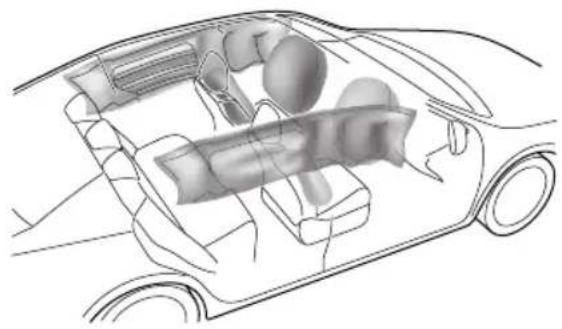
natural_image
Technical illustration of a car interior showing internal components (no text or labels)Inthecorrespondingpositionwhereairbagsarefitted, thereisawarningsignstating‘AIRBAG’.
AirbagWarningLight

Theairbagwarninglightislocatedinthe
instrumentpack.Ifthislampdoesnotextinguishor illuminatesduringdriving,itindicatesthatthereisafailure intheSRSorseatbelt.PleaseseekanMGAuthorised Repairerattheearliestopportunity.AnSRSorseatbelt faultmaymeanthecomponentsmaynotbedeployedin theeventofanaccident.
AirbagDeployment

Frontseatpassengersshouldnotplacefeet, kneesoranyotherpartofthebodyincontact with, orincloseproximitytoafrontairbag.

Tominimisetheriskofaccidentalinjuryfrom inflatingairbags,seatbeltsshouldoworn correctlyatalltimes.Inaddition,bothdriver andfrontseatpassengersshouldadjusttheir seatoprovidesufficiendistancefromthe frontairbags.Ifsideairbags/sideheadimpact protectionairbagsarefitted,bothdriverand frontseatpassengershoubeseatedto maintainsufficientdistancefromtheupper partofthebodytothesidesofthevehicle, thiswillensuremaximumprotectionwhen thesideairbags/sideheadimpactprotection airbagsaredeployed.
SEATS&RESTRAINTS

Whenairbagsaredeployed, childrenwithout properprotectionmaysufferfromserious injuryorevendeath.DONOTcarrychildren inthearmsoronthekneesduringtraveling. Childrenshouldwearseatbeltssuitableto age.DONOTleanoutofwindows.

Aninflatingairbagcancausefacialabrasions andotherinjuriesiftheoccupantistooclose totheairbagatthetimeofitsdeployment.

DONOTaffixorplaceanyobjectson, or adjacenttotheairbags. Thismay affect the airbagpassageorcreateprojectilesthatmay causeinjuryorseriousharmintheeventof airbagdeployment.

Afterdeploymenttheairbagcomponents becomeveryhot.DONOTtouchanyairbag relatedcomponents,itmaycauseburnsor seriousinjury.

DONOTknockorstrikethepositionwhere airbagsorrelatedpartsarelocated,soas toavoidaccidentalairbagdeploymentwhich maycauseseriousinjuryorevendeath.
Intheeventofacollision, the airbag control unit monitors therate of deceleration or acceleration induced by the collision, todeterminewhether the airbag should be deployed. Airbag deployment is virtually instantaneous and occurs with considerable force, accompanied by a loud noise.
Provided the front seat occupants are correctly seated and with seat belts properly worn, the air bags will provide additional protection to the chest and facial areas in the event of the car receiving a severe frontal impact.
Sideairbagsandsideheadimpactprotectionairbagsare designedtoofferadditionalprotectiontothesideofthe bodyfacingtheimpact,ifaseveresidecollisionoccurs.
IMPORTANT
•Airbags cannot protect lower body part of passengers.
•Airbagsarenotdesignedforrearcollision,minor frontalorsideimpacts,orifthevehicleoverturns; norwillitoperateasaresultofheavybraking.
- Deployment and retraction of the frontal and side air bag stakes place every quickly and will not protect against the effect of secondary impact that may occur.
- Whenanairbaginflates,afinepowderisreleased. Thisisnotanindicationofamalfunction,however, thepowdermaycauseirritationtotheskinand shouldbethoroughlyflushedfromtheeyesandany cutsorabrasionsoftheskin.
•Afterinflation,frontandsideairbagsdeflate immediately. Thisprovidesagradualcushioning effectfortheoccupantandalsoensuresthatthe driver'sforwardvisionisnotobscured.
FrontAirbags

NEVERusearearwardfacingchildrestraint onaseatprotectedbyanACTIVEAIRBAG infrontofit,DEA THorSERIOUSINJURYto theCHILDcamccur.Referto'Disablingthe PassengerAirbag'.

Frontseatpassengersshouldnotplacefeet, kneesoranyotherpartofthebodyincontact with,orincloseproximitytoafrontairbag.

Inextremecasesdrivingnveryuneven surfacesaycausirbagdeployment. Please askextranwhedrivingn unevenroads.
Airbagsaredesignedtodeployduringseriousimpacts,the followingconditionsmaycauseairbagdeployment.
- Afrontalcollisionwithunmovableornondeformable solidobjectsatahighspeed.
•Conditionsthatcancauseseriouschassisdamage,such asacollisionwithkerbstones,roadedges,deepravines orholes.
SEATS&RESTRAINTS
SeatSideAirbags

Themanufactureandmaterialoftheseat iscriticaltothecorrectoperationofside airbags. Therefore,pleaseDONOTfit seatcoverswhichmayaffectsideairbag deployment.
Intheeventofaserioussideimpact,therelevantsideairbag willdeploy(onlytheaffectedside).
•Theairbagwillbedeployedintheeventthatthesideof thevehicleisimpactedwithasolidobjectoranother vehicle.
SideHeadImpactProtectionAirbags
Intheeventofaserioussideimpact,therelevantside curtainairbagwilldeploy(onlytheaffectedside).
- Thesidecurtainairbagwillbedeployedintheeventthat thesideofthevehicleisimpactedwithasolidobjector anothervehicle.
Condition Which Airbag Not Deploy
Thedeploymentofairbagsdoesnotdependonthevehicle speed,butontheobjectthatthevehiclehits,angleof impactandtherateatwhichthecarchangesspeedasa resultofacollisionWhentheimpactforceofcollision isabsorbedorddispersedtovehiclebody,airbagsmaynot deploy;however,airbagsmaysometimesdeployaccording toimpactcondition.Therefore,thedeploymentofairbags shallnotbejudgedbasedontheseverityofvehicledamage.
FrontAirbags
Undercertainconditionsthefrontairbagsmaynotbe deployed. Some examples are listed below:
•Theimpactpointisnotcentraltothefrontofthe vehicle.
•Theimpactisnotofsufficientforce(theimpactiswith anobjectthatisnotsolid,suchasalamppostorcentral barriers).
- The impact area is high (collision with the tail gate of a truck).
- Impactstotherearorsideofthevehicle.
SEATS&RESTRAINTS
•Thevehiclerollingover .
•Frontalcollisionatananglewithguardbars.
SeatSideAirbagsandSideHeadImpact ProtectionAirbags
Undercertainconditiontheseatsideandsidehead airbagsmaynotbedeployed.Someexamplesarelisted below:
- Sideimpactsatcertainangles.
•Lightsideimpactssuchasamotorcycle. - Impactsthatarenotcentraltothesideofthevehicle, eithertoofartowardthefrontcompartmentorthe loadspace.
•Thevehiclerollingover .
•Frontalcollisionatananglewithguardbars.
•Theangledimpactisnotofsufficientforce(theimpact iswithanobjectthatisnotsolid,suchasalamppost orcentralbarriers).
•The impact is not of sufficient force (with another vehicle, stationary or moving).
•Theimpactisfromtherearofthevehicle.
DisablingthePassengerAirbag

The Passenger Airbag should only be disabled when are ar facing child seat is fitted to the front passenger seat.

Whenanadultisseatedinthefront passengerseatsurthathairbaig switchedon.
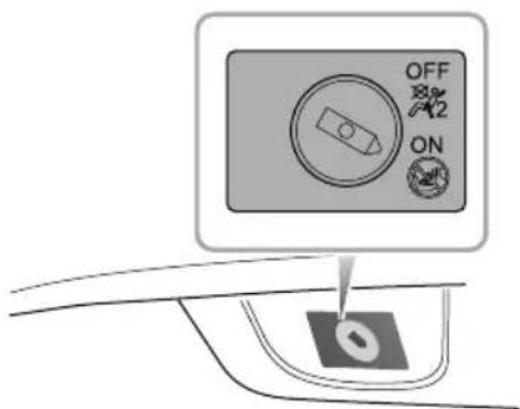
text_image
OFF ON 0SEATS&RESTRAINTS
Thepassengerairbagdisableswitchislocatedinsideofthe glovebox,Insertthekeyandturntheswitchtotheonor offpositiontoenableordisablethepassengerairbag.
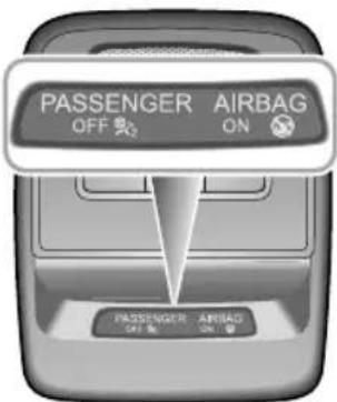
text_image
PASSenger AIRBAG OFF ON PASSenger AIRBAG OFF ONThe passenger airbag status light is located in the roof mounted interior lamp assembly. The shape of the lamp assembly varies according to the configuration of the vehicle.
WhentheswitchisturnedtotheOFFposition,theOFF indicatorlight(locatedrthePABdisplaypanelrthdamp assembly)illuminates,thisindicatesthatthepassenger airbagisdisabled.
WhentheswitchisturnedtotheONposition,theON indicatorlight(locatedrthePABdisplaypanelrthdamp assembly)illuminates,thisindicatesthatthepassenger airbagisenabled.
ServiceandReplacementofAirbags
ServiceInformation

DONOTinstallormodifytheairbag.Any changestothevehiclestructureorairbag systemwiringharnessarestrictlyprohibited.

Changestovehiclestructureisprohibited. This may affect thenormaloperationofthe SRS.

DONOTallowthesearestobefloodedwith liquidandDONOTusepetrol,detergent, furniturecreamorpolishes.

IfwatercontaminatesorenterstheSRSit maycausedamageandaffectdeployment. InthiscasecontactanMGAuthorised Repairerimmediately.
T opreventdamagetotheairbagSRS, the following areasshouldbecleanedsparinglywithadampclothand upholsterycleanerONLY:
Steeringwheelcentrepad.
Areaofdashboardcontainingthepassengerairbag.
Areofodiningforpillafinisherwhich enclosethesideheadimpactprotectionmodules. Iftheairbagwarninglampfailstoilluminate,stayson,or ifthereisdamagetothefrontorsideofthevehicle,or theairbagcoversshowsignsofdamage,contactanMG AuthorisedRepairerimmediately.
IMPORTANT
Theremovalorreplacementofanairbagmodule shouldbecarriedbutbyanMGAuthorisedRepairer. After 10 years from the initial date of registration (or installation date of fareplacement airbag), some components will need to be replaced by an MG Authorised Repairer. The appropriate page of the Service Portfoliomust besigned and stamped once the work has been completed.
SEATS&RESTRAINTS
ReplacingAirbagSystemParts

Eveniftheairbagdoesnotdeploy,collisions maycausedamagetoSRSinthevehicle. Airbagsmaynotfunctionproperlyafter damage,andcannotprotectyouandother passengerswhenasecondcollisionoccurs, whichmaycauseseriousinjuryoreven death.ToensurethatSRScanfunction properlyaftercollision,pleasegotoanMG AuthorisedRepairertocheckairbagsand repairasnecessary.
Airbagsaredesignedforusingonceonly.Oncetheairbag isdeployed,youmustreplaceSRSparts.
PleasegotoanMGAuthorisedRepairerforreplacement.
DisposalofAirbags
When your vehicle is sold, ensure that the new owner knows the vehicle is equipped with air bags, and is aware of thereplacement date of SRS.
If the vehicle is scrapped, the undeployed air bags may have potential risks, therefore, before the disposal, they must be deployed safely in a certain environment by a professional agency or an MGA authorised Repairer.
ChildRestraints
ImportantSafetyInstructionsaboutUsing ChildRestraints
It is recommended that children below the age of 12 years old should be seated on there are seat of the vehicle, in a childrestraintsystem appropriateto the children's weight and size. Infants less than 2 years old should be restrained in an infant childrestraintsystem.
It is recommended that a child restraint system that complies with UNECE-R44 or ECE-R129 standard are fitted in this vehicle. Checkmarkings on the child restraint system.
Thereareanumberofchildrestraintsystemsavailableof differenttypeandspecification.Foroptimumprotection, itisrecommendedthatyouchooserestraintsystems appropriatetothechild'sageandweight.
It is important to comply with installation instructions supplied by the child restraint manufacturer and that any child restraints system is properly secured to the vehicle. Failure to follow these instructions may cause deathor
seriousinjurytothechildinaneventofasuddenstopor accident.
- Allooccupants, including children must wear seat belts or use an appropriate child restraint.
- It is recommended that children under 12 year sofage or less than 1.5 met restall should us the appropriate child restraint fitted to there are seat.
• Onlyonechildcanbecarriedinanyonerestraint. - Donotputthechildonthelaporinarmswhensitting inanyseat.
•Alwaysadjusttheseatbackresttoacentralposition andensureitislockedinpositionwheninstallingachild seatorrestraint. - Ifinstallingarearfacingchildrestrainttotherear seat, thecorrespondingfrontseatshouldbeadjusted forward; ifinstallingaforwardfacingchildrestraint totherearseat, youmayneedtoadjusttheheight oftheheadresttothelowest; ifinstallingaforward facingchildrestrainttothefrontseat, youmayneedto removeitsheadrest.
- Neverletyourchildstandorkneelontheseatduring driving.
SEATS&RESTRAINTS
•Alwaysensurethechilddisseatedcorrectlyinthechild restraint.
- Thewaysofusingseatbeltshaveagreatinfluenceon themaximumprotectionofferedbytheseatbelt,you mustcomplywiththechildrestraintmanufacturer's instructionsonproperuseofseatbelts.Ifseatbelts arenotproperlyfastened,aminortrafficaccidentmay alsoleadtoinjury.
- Childrestraintsthatarenotfittedcorrectlymaymove andinjureotheroccupantsintheeventofanaccident oemergencybraking. Therefore, evenifthereisno infantorchildinthechildrestraint, italsoshouldbe fittedproperlyandsecurelyinthevehicle.
WarningsandInstructionsonUseofChild RestraintonFrontPassengerSeat

text_image
AIRBAG NO i i i
NEVERusearearwardfacingchildrestraint onaseatprotectedbyanACTIVEAIRBAG infrontofit,DEATHorSERIOUSINJURYto theCHILDcanoccur.

Incaseswherethereisaneedtoinstallarear facingchildrestraintonthefrontpassenger seat,usethekeytodeactivatethefront passengerairbafunction,orsevereinjury orevendeathcanoccur.
SEATS&RESTRAINTS

Oncethechildrestraintisremovedfromthe frontpassengerseat, usethekeytoreactivate thefrontpassengerairbag.

Wheninstallingachildrestraintonthefront passengerseat,movethefrontpassenger seatasfarrearwardaspossible.

Useonechildrestraintperchild.
Pleasestudythesafetywarninglabelonthesunvisor. Wherepossiblealwaysinstallchildrestraintsontherear seat.Ifitisnecessarytoinstallachildrestraintonthefront seatpleaseobservethewarningsabove.
Children's Safety and Side Airbags

Childrenshouldnotbeallowedinareas whereairbagsmaybedeployed,thereisa riskofseriousinjury.

Only recommended child restraint suitable for the age, height and weight of the child should be used.

DONOTplaceanyitemsinareaswhere airbagsmaybedeployed,thereisariskof seriousinjury.
Intheeventofasidecollision,thesideairbagscanprovide betterprotectionforthepassenger.However when theairbagistriggeredaverystrongexpansionforceis generated,ifthepassenger'sseatingpositionisnotcorrect, theairbagsoritemsinthesideairbagdeploymentarea maycauseinjury.
Whenthecorrectchildrestraintisusedtosecurethe childproperlyintherearseatandthechild'sseating positioniscorrect,thereisenoughspacebetweenthe childandthesideairbagdeploymentregionfortheairbag todeploywithoutanyhindrance,andthusprovidethe bestprotection.
SEATS&RESTRAINTS
ChildRestraintsGroups
SecuredUsing3PointlapDiagonalBelts

Please DONOT put therear facing child restraint in the front passenger seat, this may cause serious injury overvendeath.
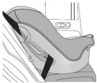
natural_image
Diagram of a car seatbelt with diagonal belt, showing seat and seat area (no text or symbols)It is recommended that children should always be seated in therearofthe vehicle in a child restraint or restraint system, and fixed with 3 point, lap diagonal seat belts.
ISOFIXChildRestraintSystems

TheISOFIXanchoragesintherearseatare designedforusewithISOFIXsystemsonly.

Childrestraintanchoragesaredesigned towithstandonlythoseloadsimposed by correctlyfittedchildrestraints. Underno circumstancesaretheytobeusedforadult seatbelts,harnesses,orforattachingother itemsorequipmenttothevehicle.
Note: When installing and using any child restraint system, always follow the manufacturer's instructions.
Note: Therearseatsfittedtothisvehicleareprovided withtheISOFIXinterface(asindicatedbythearrowin thefollowingimage),thesearedesignedtoconnectto anISOFIXchildseat.
Fastvehicle-approved SDFklestraint systemstothemountingbrackets.
2Whenusing|SOFIXmountingacketsforseat mounting,universallyapprovedchildrestraintsystems forISOFIXmaybeused.
SEATS&RESTRAINTS
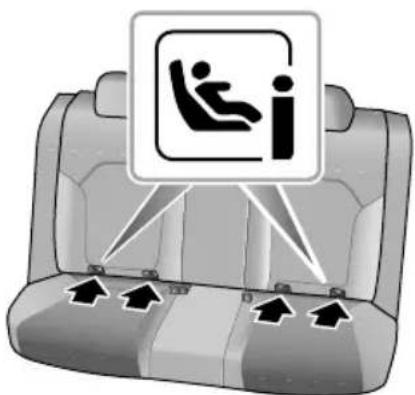
text_image
Diagram of a car backseat with a traffic sign indicating seatbelt usage, showing four seats and directional arrows.3T ofastenthetoptetherstrapofthechildrestraint system, routethetetherstrapundertheheadrestraint andattachtotheanchoragehookbeingcarefulnotto twistthestrap.Ifnotusing|SOFIXloweranchorages, usingtheseatbelt,completetheinstallationinlinewith thechildrestraintmanufacturerinstructions.
Note: When using seat mounting, universally approved child restraints systems, T op-tether must be used.
4Afterinstallationapplysuitableforcetoensurethe restraintissecurelyfastened.
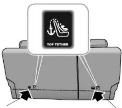
text_image
TOP TETHERSEATS&RESTRAINTS
ApprovedChildRestraintPositions
ItisrecommendedthatachildrestraintsystemthatcomplieswithUNECE-R44orECE-RI29standardarefittedinthis vehicle.Checkmarkingsonthechildrestraintsystem.
ApprovedChildRestraintPositions(fornonISOFIXChildRestraints)
| MassGroup | SeatingPositions | |||
| FrontPassenger | RearOutboard | RearMiddle | ||
| WithFrontPassengerAirbagOFFSwitch | ||||
| AirbagONAirbagOFF | ||||
| U 0group(lessthan10kg) | X | |||
| U 0+group(lessthan13kg) | X | |||
| U Igroup(9~18kg) U | X | |||
| U IIgroup(15~25kg)U | X | |||
| U IIIgroup(22~36kg)U | X | |||
| Note:Descriptionoflettersinthetable:U=Suitableforuniversalchildrestraintsystemsapprovedforthismassgroup;X=Seatpositionnotsuitableforchildrestraintsystemsinthismassgroup. | ||||
ApprovedChildRestraintPositions(forISOFIXChildRestraints)
| SeatingPosition | Massgroupcategories | ||||
| 0group0+group | Igroup | ||||
| RearfacingForwardfacingRearfacing | |||||
| Upto29lbs(13kg)20-40lbs(9~18kg) | |||||
| FrontPassenger Seat | SizeClass | NotISOFIXequipped | |||
| SeatT ype | |||||
| RearOutboard SeatISOFIX | SizeClassC,D,E | 1 | A,B,BI1 | C,D1 | |
| SeatT ype | IL2 | IL2,IUF3 | IL2 | ||
| RearCentreSeat | SizeClass | NotISOFIXequipped | |||
| SeatT ype | |||||
Note: ILSuitableforparticularISOFIXchildrestraintssystemsofthesemi-universalcategory.Pleaseconsultchildrestraints systemssuppliers'vehiclerecommendationlists;
IUSuitable for SOFIX forward facing hild estraintsystem of universat category approved using this mass group and ISOFIX size class;
TheSOFIXsizelassofbothuniversalandemi-universathildeasystemsdefinedbythecapitalettergradeA \~ G. TheseidentificationlettersaredisplayedonthelSOFIXchildseat;
SEATS&RESTRAINTS
^2 .AttimeofpublishingtherecommendedGroup0+ISOFIXbabysafetyseatistheBritaxRomerBabySafe;
^3 .AttimeofpublishingtherecommendedGroupIIISOFIXchildseatistheBritaxRomerDuo.
Note:AttimeofpublishingtherecommendedGroupII-IIIIISOFIXchildseatistheKidFixIIXPSICT.
T ableofl-Sizechildseats
Thetablegivesarecommendationforwhichl-Sizechildseatssuitwhichlocations,andforwhatsizeofchild.
ThechildseatmustbeapprovedinaccordancewithUNRegR129.
| T ypeofchildseat | FrontpassengerseatRearoutboardseatsRearcentreseat | |
| I-Sizechildrestraintsystems | XI-UX |
Note:I-USuitableforusewithforwardandrearfacingl-Sizechildrestraintsystems.
XNotsuitableforusewithl-Sizerestraintsystems.
SEATS&RESTRAINTS
Group0/0+ChildRestraint

Whenthefrontpassengerairbagisactive, neverplacearearfacingchildrestraint on thefrontpassengerseat,severeinjuryoreven deathcanoccur.
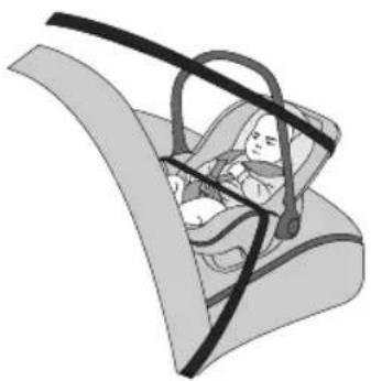
natural_image
Illustration of a baby car seatbelt in a car seatbelt (no text or symbols)Childrestraintsthatcanbeadjustedtolyingposition aremostsuitableforinfantswhoarelighterthan10kg (normallyforthoseyoungerthan9months)orthosewho arelighterthan13kg(normallyforthoseyoungerthan24 months).
GrouplChildRestraint

Whenthefrontpassengerairbagisactive, neverplacearearfacingchildrestraint on thefrontpassengerseat,severeinjuryoreven deathcanoccur.
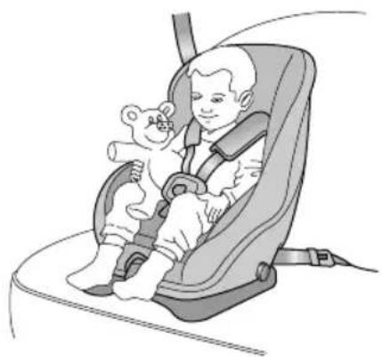
natural_image
Illustration of a child in a baby car seat with a teddy bear, no text or symbols presentBackward/forwardchildrestraintsaremostsuitablefor infantswhoseweightis9 \~ 18kg(normallyforthoseolder than9monthsandyoungerthan4yearsold).
SEATS&RESTRAINTS
GroupIIChildRestraint

Thediagonalsectionoftheseatbeltshould passacrosstheshoulderandupperbody, awayfromtheneck. Thelapsectionofthe beltshouldpassacrossthehips,awayfrom theabdomen.
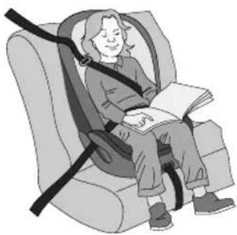
natural_image
Illustration of a person sitting in a car seat with a bandaged seatbelt, no text or symbols presentThe combination of child restraint and 3 point lap diagonal seat beltismost suitable for children whose weight is 15 \~ 25 kg (normally forthose older than 3 years old and younger than 7 years old).
GroupIIChildRestraint

Thediagonalsectionoftheseatbeltshould passacrosstheshoulderandupperbody, awayfromtheneck. Thelapsectionofthe beltshouldpassacrossthehips,awayfrom theabdomen.
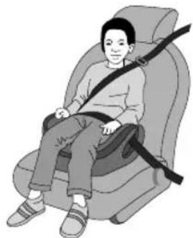
natural_image
Illustration of a person sitting in a seat with a belt bearing a shoulder strap (no text or symbols)The combination of child booster seat and vehicle 3 point lap diagonal seat belt is most suitable for children whose weight is 22 \~ 36 kg and whose height is below 1.5 m (normally forthose about 7 years old to those older than 7 years old).
Starting&Driving
148Keys
151 ChildProofLocks
152AlarmSystem
160StartingandStoppingthePower System
164 PedestrianAlertControlSystem
165EconomicalandEnvironmentalDriving
168ChargingandDischarging Requirements
186ElectricDriveT transmission
195 BrakeSystem
206AdaptiveCruiseControlSystem
215ParkingAidSystem
218 RearDriverAssistanceSystem
224TyrePressureMonitoringSystem (TPMS)
225 DrivingAssistSystem
242LoadCarrying
STARTING&DRIVING
Keys
Overview

Pleasekeepthesparekeyinasafeplace-not inthecar!

It is recommended that spare keys are not kept on the same key ring, sincethism may cause interference and prevent correct key recognition and therefore prevent the correct operation of the vehicle powers system.

Thesmartkeycontainsdelicatecircuitsand mustbeprotectedfromimpactandwater damage,hightemperatureandhumidity, directsunlightandtheeffectsofsolvents, waxesandabrasivecleaners.
Y ourvehicleissuppliedwithtwosmartkeys,eachone containsabackupmechanicalkeyblade,thiswilloperate thedriverdoormechanicallock.Thesmartkeyssupplied areprogrammedtothesecuritysystemonthecar,anykey thatisnotprogrammedtothecarwillnotoperatethe keylessentryfunctionorthevehicleimmobiliser.
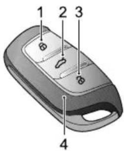
text_image
1 2 3 4ILockButton
2T ailgateButton
3UnlockButton
4SmartKey
Thesmartkeyonlyworkswithinacertainrange.It's workingrangeissometimesinfluencedbythekeybattery condition,physicalandgeographicalfactoforsafety consideration,afteryoulockyourvehiclebythesmartkey, pleaserecheckifthevehicleislocked.
If your key is lost/stolen or broken, are replacement can be obtained from a MGA authorised repairer. The lost/stolen
STARTING&DRIVING
keycanbedeactivated.Ifthelostkeyisfound,anMG AuthorisedRepairercanreactivateit.
Note: Anykeymadeprivatelymaynotstartthe vehicle, and may affect the safety of your car. To obtain suitable key replacement, it is recommended that you can consult an MGA authorised Repairer.
Note: Thenewkey cannot be offered to you immediately because it requires programming the vehicle by the MGA authorised Repairer.
Noacidoperatingthesmartkeycloseto strongradiointerferencedevices(suchasnotebook computersandotherelectronicproducts),thenormal functionofthekeymaybeaffected.
ReplacingBattery
Pleaseusethepictureguidetoreplacethesmartkey batteryifanyofthefollowingconditionsoccur:
- Thesmartkeylocking/unlockingfunctionrangeis reduced;
- Themessagecentrewilldisplay"RemoteKeyLow Battery, PleaseReplace".
A
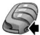
B
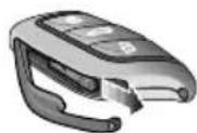
C
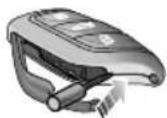
D
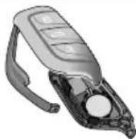
Pressthebutton(A)onthesmartkeytoejectthe decorativetrim.
Removethackupmechanicakey(B)tharrowed direction.
Using suitable ablatedoolinsertheointo theidethkey(C)carefullyprisofthebattery coverandseparatetheupperandlowercasings(D).
Removethebatteryfromtheslot.
STARTING&DRIVING
5Putthenewbatteryintheslot, and makesureitisin fullcontactwiththeslot.
Note: Makesurethatthepolarityofbatteryis correct('+'sidefacingdown).
Note: It is recommended to use a CR2032 battery.
6Refitthecoverandpresstightly,ensuringthegap aroundthecoveriseven.
7Refitthemechanicalkey,andrefitthedecorativetrim.
8Operatethevehiclepowersystemtoresynchronize thekeywiththevehicle.
IMPORTANT
- Useofanincorrectorinappropriatebatterymay damagethesmartkey. Thenewreplacement'srated voltage, sizesandspecificationsmustbethesameas theoldone.
•Incorrectfittingofthebatterymaydamagethekey.
- Disposaloftheusedbatterymustbestrictlyin accordancewithrelevantenvironmentalprotection acts.
STARTING&DRIVING
ChildProofLocks

NEVERleavechildrenunsupervisedinthe vehicle.
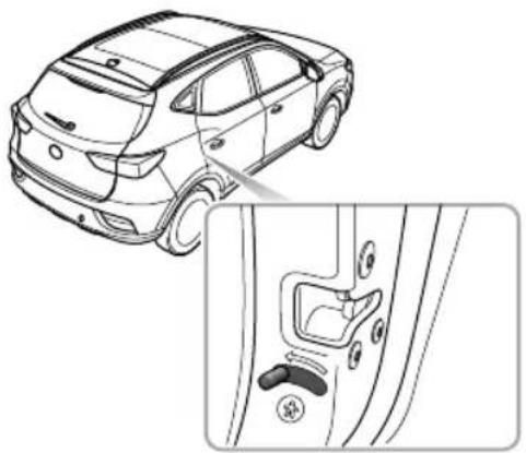
natural_image
Line drawing of a car showing the side profile and rear door lock mechanism (no text or symbols)- Openthereardooronthecorrespondingside,move thechildprooflocklevertothelockpositioninthe directionofthearrowtoengagethechildprooflock; - Movethelevertotheunlockpositioninthereverse directionofthearrowtodisablethechildprooflock. Withthechildprooflocklocked,thereardooronthe correspondingsidecannotbeopenedfrominsidethecar, butcanbeopenedfromoutsidethecar .
Stepsforenablingordisablingthechildprooflocksareas follows:
STARTING&DRIVING
AlarmSystem
Y ourcarisfittedwithanelectronicanti-theftalarmand powerimmobilisationsystem.T oensuremaximumsafety andoperationconvenience, westronglyrecommendyou tocarefullyreadthischaptertofullyunderstandthe activationanddeactivationofanti-theftsystems.
PowerImmobilisation
PowerImmobilisationisdesignedtosafeguardthevehicle fromtheft. Thepowerimmobilisationsystemcanonlybe deactivatedtostartthecarbyusingthematchedkey.
PresstheSTARTSTOPbuttonontheinstrumentpanel, onceavalidkeyisdetectedinthevehicle,immobilisation systemwillbedeactivatedautomatically.
Ifthemessagecentredisplays"SmartKeyNotDetected"or "PutKeyIntoBack-upPosition"orthepowerimmobiliser systemwarninglampilluminates,pleaseputthesmartkey atthebottomofthecentreconsolecupholder(referto "AlternativeStartingProcedure"in"StartingandStopping thePowerSystem"section),ortrytousethesparekey.
Ifthecarcanstillnotbestarted,pleasecontactMG AuthorisedRepairer.
STARTING&DRIVING
BodyAnti-theftSystem
LockingandUnlocking
Whenthevehicleislocked, theindicatorlampsflashthree times; whenitisunlocked, theindicatorlampsflashonce.
OperationofDoorLockSystem(Key)
KeyLocking
- Usingtheremotekeytolock:pressthelockbuttonon thekeytolockthecarafterclosingthedoors,bonnet andtailgate.
- Usingthemechanicalkeytolock:partiallyoperate thedoorreleasehandle,usingasuitableflatblade tool,insertthetoolintotheundersideofthetrimand carefullyremovethedoorlocktrimcover,insertthe keyintothedriverdoorlockandturncounterclockwise tolockthecar.
KeyUnlocking
• Usingtheremotekeytounlock:presstheunlock buttononthekeytounlockthecar.
- Usingthemechanicalkeytounlock:partiallyoperate thedoorreleasehandle,usingasuitableflatblade
tool, insert the tool into the underside of the trim and carefully removed the driver door lock trim cover, insert the key into the driver door lock and turn clockwise tounlock the car.
FindMyCar
Afterthevehiclehasbeenleftinalockedconditionfora fewminutespressingthelockbuttonagainontheremote keywillenableFinM\CafunctionThifunction willidentifythecarbymeansofanaudibleandvisualalert. PressingtheLockbuttononthehandsetagainwillsuspend thisoperation.PressingtheUnlockbuttonwillcancelthis operation.Thisfeaturecanbesetonthentertainment display.
Note: If the vehicle powers system is not switched to the ACC/ON/READY position within 15 seconds after the vehicle is unlocked with the mechanical key, the immobilisation alarm will be triggered.
Note: If nop anels are opened within a few seconds after the vehicle is unlocked by using theremote key, alldoor will automatically re-lock.
STARTING&DRIVING
OperationofDoorLockSystem(Keyless)
Thekeylessentrysystemcanlockandunlockthedoors andtailgateaslongasyoucarrythesmartkeyandapproach tothecar.
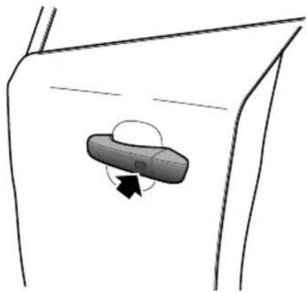
natural_image
Simple line drawing of a car door with a moving device inside (no text or symbols)IMPORTANT
Thesmartkeymustbewithin1.5metresofthevehicle forthekeylesssystemtooperatecorrectly.
KeylessLocking
AfterswitchingtheSTART/STOPSwitchtotheOFF positionandexitingthecar,pressthedoorhandlebutton oncebeforemovingawayfromthecartolockalldoors andtailgate(noneedtopressthelockbuttononthe key).Note,thiswillalsoarmthealarmandimmobilise thevehicle.
KeylessUnlocking
Pressthebuttononthefrontdoorhandleoncetounlock thecar ,thenpullthedoorhandletoopenthedoor.
Note: Whenthevehicleislocked, if you are within the smart key range and operate the door handle button, but carry out no further action, after 30 seconds the vehicle will automatically re-lock itself to remain secure.
IMPORTANT
Afterthedoorislockedbyusingthekey,pressthe buttononthedoorhandletounlockthecar.Ifthecar cannotbeunlockedorlockednormally,seekanMG AuthorisedRepairer.
Mislock
Ifthedriver'sdoorisnotfullyclosedwhenthesmartkey lockbuttonispressed,ortheSTART/STOPSwitchhas notbeenswitchedOFF ,thevehiclehornwillsoundonce, indicatingamislock.Inthiscase,noneofthedoorswill lock,thealarmsystemwillnotbearmed.
Ifthedriver'sdoorisclosed,thepassengerdoor,bonnet andtailgatearenotfullyclosed,thehornsoundsonceto indicatemislockwhenthecarundergoeslockingoperation. However,the'partialarming'attributesofthesecurity systemwillenableasmuchofthesystemtobearmedas possible(allfullycloseddoors,bonnetortailgateapertures willbeprotected,butanopendoorwillnot!).Thealarm indicatorwillflash.Assoonastheopenapertureisclosed, thesystemwillautomaticallyreverttoanarmedstate
InadvertentLockingofKeysinVehicle
If the vehicle is locked using the mechanical key blade or handset whilst a smart key/s remain inside, the following actions will occur:
- Onesmartkeylockedinthevehicle-The immobilisationreleasefunctionofthesmartkeylocked inthevehicleissuspended,thelockandunlockfunction ofthesmartkeyisretained.Thevehiclewillnotchange powerataReinstatthimmobilisrelease functionofthesmartkeylockedinthevehiclethe secondsmartkeyshouldbeusedtounlockthevehicle. Thefunctionwillautomaticallybereinstated.
- Bothsmartkeyslockedinvehicle-Theimmobilisation releasefunctionofbothsmartkeyslockedinthevehicle issuspended,thelockandunlockfunctionofthesmart keysisretainedthevehiclewillnotchangepower state. Thereinstatementofkeyfunctionscanonlybe carriedoutusingtheapproveddiagnostictool.Consult anMGAuthorisedRepairerimmediately.
STARTING&DRIVING
Anti-theftAlarmSounder
If the anti-theftalarm has been triggered, the carhorn will sound continuously. Press the UNLOCK button on the key, the anti-theftalarm will be deactivated.
InteriorLockandUnlockSwitch
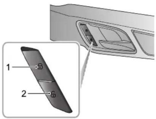
text_image
Diagram showing a device panel with labeled parts, including a close-up view of the interior and a magnified view of its internal structure.ILockSwitch
2UnlockSwitch
Whentheanti-theftalarmsystemisnotinoperation,press thelockswitch(1)tolockalldoors;presstheunlock switch(2)tounlockalldoors.
Note: If the anti-theftalarmsystem is switched on, pressing the lock/unlock button will not lock/unlock the doors but will trigger the alarms system.
Ifthedoors, bonnetandtailgateareclosed, pressthe interiorlockswitch. They yellowindicatorontheinterior lockswitchilluminates.
lfamislockiscausedbynon-driverdoor ,tailgateorbonnet, presstheinteriorlockswitch. Theyellowindicatoronthe interiorlockswitchilluminates.
InteriorDoorHandles
Whentheanti-theftalarmsystemisnotinoperation, use theinteriordoorhandletoopenthedoor:
I Pulltheinteriordoorhandleoncetounlockthedoor.
2Pulltheinteriordoorhandleagaintoopenthedoor.
SpeedLock
Allthedoorswillbelockedautomaticallywhentheroad speedexceeds 10mph(15km/h).
AutomaticUnlock
WhenthevehiclepowersystemisswitchedtotheOFF position, allthedoorswillbeunlockedautomatically.
STARTING&DRIVING
T ailgate

If the tail gate cannot be closed due to the type of cargoloaded, besure to close all windows during driving, select the face distribution mode of the air condition, and set the blowertomaximspeed, so as to decrease any fumesentering the vehicle.
T ailgateOpenMode
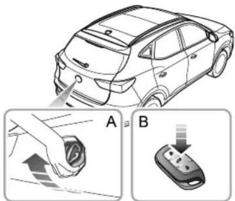
text_image
Diagram illustrating car door repair process with labeled steps A and B showing hand positioning and disassembly of a remote control.Thetailgatecanbeopenedbyusingthefollowing2 methods:
I Whenthevehicle is unlocked or thematched key appears within Imrangearound the tailgate, directly openthetailgate by turning over the emble on the tailgate (Figure A).
2WhenSTART/STOPSwitchintheOFFposition,press thereleasebuttonontheremotekey(FigureB)for morethan2secondstoopenthetailgate.
EmergencyT ailgateOpening
The emergency tailgaterelease access is located in the centre of the tailgatetrim.
Folddowntherearseattogainaccess,removethe blankingplug,androtatetheemergencyopenknob counterclockwisetoopenthetailgatefrominside.
STARTING&DRIVING
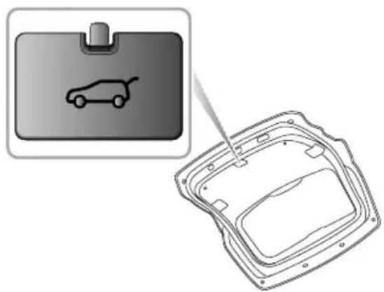
natural_image
Diagram showing a car icon inside a device panel and its internal structure, with no visible text or symbols.STARTING&DRIVING
StartingandStoppingthePower System
STARTSTOPSwitch
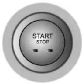
text_image
START STOPThekeylessSTARTSTOPswitchislocatedinthefascia totheleftofthesteeringcolumn,itisapushbuttonstyle switch.T ooperatetheswitchthesmartkeymustbeinside thevehicle.
Theoperationalstatusdisplaysareasfollows:
IndicatorOff(OFF)
Iftheswitchhasnotbeenoperatedandthereareno indicatorsilluminated,thepowersystemisOFF .Thepower seatsandelectricdoormirrorsremainoperational.
YellowLight(ACC)
PressingtheSTARTSTOPbuttonwithoutthefootbrake beingappliedwhilstthevehiclepowersystemisOFFwill placethesystemintheACCstate,thiswillilluminatethe yellowindicatorintheswitchbutton.TheACCposition allowsoperationofcertainancillariessuchpower windows.
GreenLight(ON/READY)
WhilstintheACCstate,pressingtheSTARTSTOP buttonwithoutthefootbrakebeingappliedwillplace thesystemintheONstate,thegreenindicatorwill illuminaThiswillowheremainingelectrical systemstöoperate.
Pressing ST ARST Outtowir Relected and the footbrak appliewillactheehicie the READY state, the green indicator willilluminate and the word READY will appear in instrument panel information display this indicates that all electrical
systemswilloperateandthevehicleisreadytobe driven.
Note: WhilstintheOFFstate, ifthedriverexits thevehicleleavingthesmartkeyinside, afterthe secondoperationofre-openingthedriver'sdoor, the instrumentpackmessagecentrewilldisplayawarning messagetoindicatethatthekeyisstillinthecar.
Note: Toremovetheelectricshiftcontrolknob from PthevehiclemustbeinanON/READYstateandthe footbrakeapplied.
If your carissubjecttostrongradiosignalsthekeyless entry and start systemsmaysuffer from interference and not function correctly. Please see the 'Alternative Starting' procedure.
READYMode
SettingthepowersystemintoREADYmode:
I Ensure all unnecessary electrical loads ares switched off.
2 Ensure the parking brake is applied.
3EnsurePorNisselected(Iftheshiftcontrolknob isinanyotherpositionthepowersystemcannotbe switchedtotheON/READYstate)
4Pressbrakepedal.
5PresstheSTART/STOPSwitch(donotholdthebutton in, releaseimmediately)
STARTING&DRIVING
IMPORTANT
•IfthevehiclewillnotenteraREADYstate,please checkforanywarningindicatorsormessagesdisplayed intheinstrumentpackmessagecentre.Inextremely lowtemperaturespleaseallow5minutesbetween powerupattempts,ifafter3attemptsthepower statecannotbesettoREADYpleaseconsultanMG AuthorisedRepairerorbreakdownservice.
- DonotleavethepowersysteminanACCor ON/READYstateforlongperiodsoftime,excessive useofelectricalequipmentmayleadtotoadischarged battery.
•Thevehicleisfittedwithananti-theftsystem.
Independentlysourcedkeysmaynotallowvehicle entryandsystempowerup.Anynewkeyswillrequire programmingusingthemanufacturerssoftware.
•Y ourcarisfittedwithcomplexelectroniccontrol systempleasusedtheradio
transmissionorelectromagneticdevicesarekeptaway fromthesmartkeyandcentreconsolecubbyareas.
Theymayausinterferencendoperationissues.
Pleaseseethe'AlternativeStarting'procedure.
AlternativeStartingProcedure
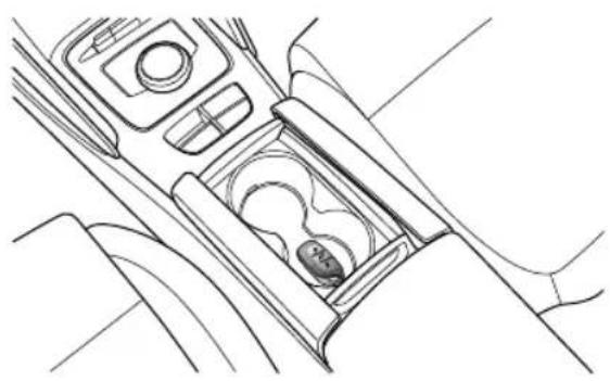
natural_image
Line drawing of a car intake canal with no text or symbolsIfthevehicleislocatedinanareawheretherearestrong radiosignalscausinginterferenceorthesmartkeybattery conditionislow,pleaseusethefollowingstepstoattempt tostartthecar:
Placethesmartkeycentrallyinthecentreconsolecup holdercubbyboxwiththebuttonsfacingupward-as shownintheillustration.
STARTING&DRIVING
2EnsurePorNisselected, pressthebrakepedaland thenpressSTART/STOPSwitchtopowerthevehicle.
Ifthevehiclepowersystemcannotbechangedafterthe carhaslefttheareaofstrongradiointerferenceorhad thesmartkeybatteryreplacedpleaseconsultanMG AuthorisedRepairer.
IMPORTANT
TheAlternativeStartingProcedureshouldonlybe requiredifthesmartkeybatteryisveryloworflat. Oncethevehiclehasbeenremovedfromtheareaof excessiveeradiointerferencethekeylessentryandStart Stopsystemsshouldreturntonormal.
SwitchingthePowerSystemOFF
SettingthepowersystemtoOFF:
I After bringing the cartoahalt, ALWAYS maintain brake pedal application.
2Usingtheelectronicshiftcontrolknobselect(P), this will automatically apply the parking brake-please check that the parking brake is applied.
3PressSTART/STOPSwitchtoshutdownthepower system.
Note: Pleaseobservetheparkbrakewarninglight andmessagedisplayedintheinstrumentpack messagecentreconfirmingthattheparkingbrake isappliedbeforeexitingthevehicle.
STARTING&DRIVING
PedestrianAlertControlSystem
Inordertoimprovethesafety,yourcarisfittedwitha
PedestrianAlertSystem.Whenthevehicleistravellingat alowspeed,thesystemcontrolsaspeakerthatsoundsto remindpedestriansinthevicinityofyourpresence.
Strategiesofsoundingwarnings
Thespeakersoundswhenallofthefollowingconditions aremet:
I ThevehicleisREAD Y;
2ThepedestrianAlertsystemisfaultfree;
3Duringacceleration,thevehiclespeedislessthan 19mph(30km/h);duringdeceleration,thevehicle speedislessthanorequalto 12mph(20km/h).
EconomicalandEnvironmentalDriving
Running-in
Thebrakesandtyresneedtimeto'bed-in'andadjustto thedemandsofeverydaymotoring.Duringthefirst900 miles,pleaseavoidheavybrakingwherepossible.
EconomicDriving
Thewayinwhichyoudriveyourcarhasasignificant bearingonthelifespanofthecarandbattery.
DriveSmoothly
Anticipatingobstructionsandslowingdownwellin advance,avoidstheneedforunnecessaryaccelerationand harshbraking.Asmoothdrivingstylenotonlyimproves battery/distanceperformance,butcanreducetheamount ofwearonthebrakesandtyres.
AvoidDrivingatMaximumSpeed
Powerconsumptionandnoiselevelsrisesignificantlyat higherspeeds.
DrivingForeseeingly
Avoidroadswithtrafficcongestionortrafficjams. Foresee roadcongestionasearlyaspossible, keepenoughdistance fromthecarinfrontduringdriving, andslowdownintime. Avoidlengthyandheavybrakepedalapplicationswhenthey arenotnecessary, thesewillcausethebrakestooverheat andcauseprematurebrakewear.
STARTING&DRIVING
UseofElectricalEquipment
Useofelectricalequipmentwillreducethepoweravailable fromthebattery.Whilstitisessentialtomaintain acomfortableinteriorenvironment,excessiveuseof systemssuchasA/Cwillincreasepowerconsumptionand reducethevehiclerange.
DrivinginSpecialEnvironment
DrivinginRainorSnow

Emergencybraking, accelerating and steering onslipperyroadswillreducethevehicle's handlingperformanceandgrip.
- Whenraining, the windows may fog, reducing visibility (Use the Air-conditioning demist function).
•Gripwillbereduced, sopleasedrivecarefully.
Reduce speed, wherein avoid quaplaning the effect of a film of water between the tyres and the road) affecting steering and braking performance.
DrivingthroughWater
Avoiddrivingthroughfloodsafterheavyrain,whichmay leadtoseriousdamagetothevehicle.
CheckandService
CheckTyrePressuresRegularly
Under-inflatedtyresincreasetherollingresistanceofthe carwhich,inturn,increasespowerconsumption.Overor under-inflatedtyreswearoutmorerapidlyandalsohavea detrimentaleffectonthecar'shandlingcharacteristics.
DonotCarryUnnecessaryLoads
The additional weight of unnecessary load swastes power, especially in stop/start conditions where the car is frequently required to set off from stationary.
MaintainCorrectFour-WheelAlignment
Maintainthecorrectwheelalignment.Avoidcollisions withthekerbandreducespeedonunevenroadsurfaces. Outofspecificationwheelalignmentwillnotonlyleadto excessivetyrewear,butalsoincreasestheloadandpower consumption.
STARTING&DRIVING
ChargingandDischarging Requirements

Undernormalcircumstancesitisstrongly recommended that you use as low charging method, avoid constant or regular use of rapid chargers.

Priortousinganychargingequipmentplease inspectthesockets,plugsandcablesforany damage.DONOTuseanyequipmentthat showssignsofmisuseordamage.

It is recommended that the charging cable be connected to the charging device before connecting to the vehicle and charging commences.

DONOTattempttoswitchthevehiclepower systemtoREADYduringcharging.

Afterchargingcompletion,switchoffthe charger(wherenecessary),disconnectthe cablefromthevehicle,fiththewaterproof blankingplugs,closethechargingpointdoor. Ifnecessaryyoucanthendisconnectthe cablefromthecharger(whereapplicable).

Whilstchargingthecaronrainydays, where possible, please avoid connecting the charger during torrential rainorstorms. If excessive waterisevident around the charging plugs please use suitable cloth to dry the area as best possible before removing the waterproof blanking plugs and connecting the charging cables.

DONOTtouchthechargingconnector chargingplugwhenyourhandiswet.

DONOTstandinwaterorsnowwhen connectingordisconnectingthecharging cable.
STARTING&DRIVING
DONOTattempttochargewhenthe chargingconnectorandplugarewet.
Alwayskeepthechargingconnector and chargingplugincleanandinadrycondition. Besuretokeepthechargingcablein aconditionwherethereisnowateror moisture.
Onlyusethecorrectchargerforchargingthe electricvehicle.Usinganyotherchargeror connectorconfigurationmaycausefailure.
T akecarenottodropthechargingconnector. Thiscouldresultindamage.
STOPchargingordischargingimmediatelyif youfindanythingabnormal,suchassparks, burningorsmoke.
Always hold the charging connector handle of plug hen connecting removing the chargingable for the ablation itself (without using the handle), the internal wires may disconnector get damaged. This may lead to electric shock or fire.
High voltage charging equipment uninterfereneth electroniedithines.
usingmedicalelectricaldevicesuds pacemaker please consultyourdoctor abowhetherargidischarging
yoelectrichiolipatte operationofthedevice.Insomeinstances, electromagnetivavethatargenerated frotheargeneriouslyimpact medicalelectricdeviceoperation.
NEVERuseahighpoweredjetwashdirectly onthechargerdoorortocleanaroundthe chargepoint.
STARTING&DRIVING
ChargingY ourVehicleatHome
Whilst your MG has been supplied with a home charging kit, it is essential that you check with a qualified electrician that the infrastructure of your property will support the charging equipment. Please seek qualified advice that your current electrical supply and circuit will support the requirement of the charging equipment.
InstalledChargingPoints
Various companies will supply and install charging points to your property, MG insist that only qualified reputable suppliers and installers are used - failure to have the correct equipment installed by a qualified professional may result in overloaded circuits and fire.
HomeChargingGuide
ONLYusecertifiedapprovedequipment.
ONLYusequalifiedsuppliersandinstallers.
Whenthebatteryisfullycharged, disconnect the cable plug from the vehicles socket-ifitis necessary to interrupt the charging of the vehicle, isolat the powers supply first, thendisconnect the vehicle plug.
NEVERallowwaterorfluidstoenterorcontaminateyour chargerorvehiclechargingsockets.
NEVERusedamagedchargingpoints, equipmentor sockets.
STOPchargingimmediatelyifyouseeanythingunusual, smellsomethingburningorseesparks.
ALWAYSfollowtheoperatinginstructionssuppliedwith yourchargingequipment.
Note: charging in power supply infrastructure must be installed. Similarly suitable qualification personnel should be approved installation companying by materials recommended by them.
ChargingandMedicalConditionAwareness

Highvoltagechargingequipmentcancreate areasofstrongelectromagneticinterference, thismaycauseoperationalissueswith electronicmedicaldevices.
When using medicale electrical device such as pacemakers or cardioverter defibrillators (ICD's), please consult your doctor about whether charging your electric vehicle will an impact on the operation of the device. In some instances, electromagnetic wave that are generated from the charger can seriously impact medicale electric device operation.
Note: Therearenocautionsissuedaboutmedical deviceswhenthecarisnotcharging.Itisperfectlysafe forindividualsfittedwithpacemakersorcardioverter defibrillatorstodriveorrideinthevehicle.
ChargingPort
Thechargingportislocatedbehindthechargingportdoor mountedinthefrontbumper .Itisincorporatedintothe masterlockingsystem.
T oopenthedoor,ensurethevehicleisunlocked,press thechargingportdoorandrelease-thedoorwillopento openthewaterproofplugcovers.
Opentheplugcoverstorevealthecombinedchargingport.
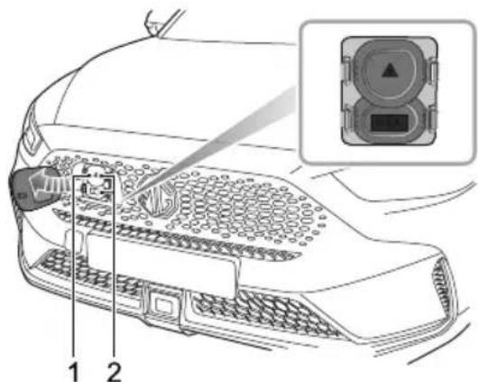
text_image
Technical diagram of a car's front panel with labeled components and an inset showing a sensor or connector.STARTING&DRIVING
ISlowandFastChargePort-7Pin-T ype2Plug
2RapidChargePort-7Pinand2Pin-CCST ypePlug
Theupperplugcoversthe7pinslow/fastchargingsocket (1). Thelowerplugcoverstherapidchargingsocket(2).
Note: Inordertousetherapidchargersocket, both waterproofplugcoverswillrequireremoval.
Aftercharging, refitthewaterproofplugcovers, closethe chargingportdoor, pushthedoorfullyhomeuntilthelatch locates.
ALWAYSensurethatanyexcesswaterisremovedfrom theportareabeforeconnectinganychargingdevice.
ChargingPortElectronicLock
Inordertopreventthechargingconnectorandcablebeing disconnectedinadvertentlyduringcharging,thecharging socketfeaturesanelectroniclockingmechanism.
The electronic clock is activated as soon as the vehicle begins charging, and remains in a locked state until the charging is finished or interrupted.
Whilst the charging cable is connected DONOT attempt to remove the plug.
ManuallyReleasingtheChargingPortLockin EmergencySituations
The vehicle features an emergency released device for the charging portlock.
T oaccessthemanualrelease,raisethebonnetandlocate thereleasecableontheO/Softheradiatorcowling assembly-seepicture.
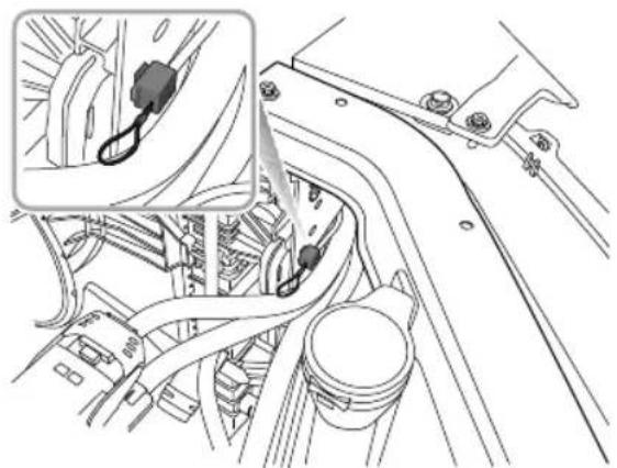
natural_image
Technical line drawing of a mechanical assembly with a close-up inset showing a cable or connector (no text or symbols present)Pullthereleasecablehandle,removetheconnectorplug whilstmaintainingtensiononthecablethiswillreleasethe lockingdevice.
ElectricChargingIdentifierLabel * IdentifierLabelonSlowChargingKit
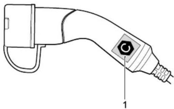
natural_image
Line drawing of a handheld electric shock absorber with labeled component (no text or symbols beyond label)IACchargingidentifierlabel Note:Userscanpurchaseaslowchargingkitfroman MGAuthorizedRepairer.
STARTING&DRIVING
IdentifierLabelsonChargingPort
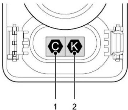
text_image
C K 1 2IACchargingidentifierlabel
2DCchargingidentifierlabel
PrecautionsforACorDCcharging
Afteropeningthechargingportdoor,checkthecharging identifiersymbolontheplugcover .Checkthecharging connectoridentifiersymbolontheACorDCcharger
cable. Afterchecking that the alphabetic characters of the charging identifiers symbols match, proceed then next charging step.
Note: Riskoffailure, fireorinjuryetc. when using charging connector with matched identifier symbols.
Electricchargingidentifierlabelsymbolable
| Supply Type | Configuration | Type of Accessory | Voltage range | Identifier |
| AC | 7P | Vehicle connector and vehicle inlet | ≤480V |  |
| 7P-EXP | Vehicle connector and vehicle inlet | 50V–500V |  |
STARTING&DRIVING
RapidCharging
Note: Pleasereadanyequipmentoperating instructionscarefullypriortousingtherapidcharging station. Eachtypeofchargermayusedifferent instructions.
Note: The cable of the charging plug should be shorter than 30m.
If you have any doubts, please seek professional assistance.
RapidChargingSafetyPrecautions
- Beforeconnectingtherapidcharger, switchthevehicle powersystemOFFandwait10seconds.
Note: If at any time during the charging process you should want to check the state of charge, please switch the vehicle powers system to the ON position. The high voltage battery state of chargewill bed displayed in the message centre in the instrument pack.
Not Considering the safety and service of the high voltage battery, he using a rapid charging station to charge the vehicle battery will not be completely charged and therefore in instrument
packmaydisplaylessthan100%powerIfyouhavea longjourneyplanned,itisrecommendedthatyouuse aslowchargingpointtochargethevehiclesoasnot toaffectyourjourney(BatteryPackType I).
STARTING&DRIVING
SlowCharging
Note: Carrying out a full slow charge is the only way for the high voltage battery to reach the optimal equilibrium state (equalisation charge).
Highvoltagebatterychargersareavailablewithvarious poweroutputs. Chargerswithoutputsofupto3kW aregenerallyconsideredasslowchargers,7-22kWare consideredfastchargersandrapidchargersareavailablein ACorDCOutputs.GenerallytheACchargersarerated at43kWandtheDCchargersat50kWplus.
Chargingtimesaredependentonchargeroutput.
T ocarryoutanequalisationslowcharge,itis recommendedthatthechargeroutputdoesnotexceed 7kW.
ACChargingPoints
IMPORTANT
PleaseensurethatonlychargepointsthatmeetIEC 61851andIEC62196areusedtoconnecttoyour vehicle.
UsinganACchargingdevice:
Ensure the vehicle powers system is OFF and all doors are closed.
Qpenthechargingportdoor, removethewaterproof plugcoverfromthe7pinchargingplugconnector.
Bugthecablefromthechargerpointintothevehicle. Lockthevehicle.
④ncompletionofthecharge, shutoffthepower, unlockthevehicleanddisconnecttheplugfromthe vehicle.
Ensure the charges socket is free from debris, fit the waterproof plug cover. Close the charging point door.
Note: If at any time during the charging process you should want to check the state of charge please switch
thevehiclepowersystemtotheONposition. Thehigh voltagebatterystateofchargewillbedisplayedinthe messagecentreintheinstrumentpack.
ResidentialCharging
During the charging operation the vehicle powers system must be OFF. Carry out the following procedure to charge the vehicle:
I Ensure the vehicle powers system is OFF and all doors are closed.
2Openthechargingportdoor,removethewaterproof plugcoverfromthe7pinchargingplugconnector. Ensurethesurroundingsareclean,dryandfreefrom debris.
3Connectthe7pinchargingplugtothesocketonthe vehicle.
4Connectthechargingdeviceplugtothedomestic electricitysupply.Lockthevehicle.
5Oncompletionofthecharge,shutoffthepower, unlockthevehicle,disconnecttchechargingcablefrom thevehicle,andthenthedomesticplug.
6 Ensure the charges socket is free from debris, fit the waterproof plug cover. Close the charging point door.
STARTING&DRIVING
Note: If at any time during the charging process you should want to check the state of charge, please switch the vehicle powers system to the ON position. The high voltage battery state of chargewill bed displayed in the message centre in the instrument pack.
ChargingInformation
Atthebeginningofthechargingprocess,thefollowinginformationwillbedisplayedwithintheinstrumentpackmessage centre.
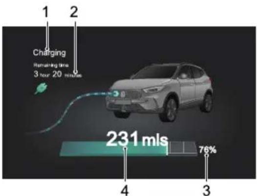
text_image
Charging Refraining time 3 hour 20 minutes 231 mls 76% 4 3I Chargingstatus
2Chargingtime
3Highvoltagebatterypackstatus
4Drivingrange
Note: The information displayed on the instrument pack may be different based on vehicle configuration.
STARTING&DRIVING
EqualisationCharging
Equalisationchargingmeansthatafteranormalcharging processthebatterymanagementsystemwillenteramode whereitwillattempttoequalisethechargeofevery batterycell.
Ifanequalisationchargehasnotbeencarriedoutforsome time,themessagecentreintheinstrumentpackwilldisplay 'PleaseSlow-chargetheV vehicle'.Pleasereferto'Slow Charging'inthe'StartingandDriving'section.
Onaverageittakesatleast1 1.5hours(batterypacktype1)or8.5hours(batterypacktype2)tocompletecharge thatincludestheequalisationcharge.
Note: Ambienttemperatureshaveaneffecton chargingtime may takelongertocompletea chargewhentheambienttemperaturesarelow.
ChargingTimes
Chargingmode, high voltage battery, depending upon numerous factors, these include current capacity, charging mode, ambient temperature and device type/power.
RapidChargingTime
Rapidhargersvillaripoweoutputaverage willtakeapproximately40-60minutestochargethehigh voltagebatteryupto80%(80%displayedinIPK)usinganaveragerapidcharger.
Note: Ambienttemperatureshaveaneffecton chargingtime may takelongertocompletea chargewhentheambienttemperaturesarelowor high.
SlowChargingTime
Onaverageittakesapproximately 10.5 hours (batterypack type1) or 8 hours (batterypack type2) to charge the high voltage battery from low battery warning to 100% (charge quantity can be checked using the instrument pack).
STARTING&DRIVING
- Atlowtemperaturesthechargingtimewillbeextended.
- Ifanequalisationchargehasnotbeenconductedfora longtimetherequiredchargetimewillbeextended.
- Anequalisationchargemustbecarriedoutpriorto usingthecarafteralongperiodofstorageornonuse. Inthesecasesthechargingtimewillbeextended.
Note: Theslowchargingnotesaboverelatetousing anACchargingdevice. Useoftheslowcharging deviceusingadomesticpowersupplycanincreasethe chargingtimesbyupto3times.
IndicativeChargingTimesforBatteryPackTypeI
Note: Thesetimesareonlyaguide.
| Rapidcharging | Fromalarmstatus(thehighvoltagebatterylowwarningdisplayedintheinstrumentpackmessagecentre)to80%,ittakesalmost40minutes. | |||
| Slow charging | Residential electricity | Fromalarmstatus(thehighvoltagebatterylowwarningdisplayedintheinstrumentpackmessagecentre)to100%(thehighvoltagebatterstatehargedisplayedintheinstrumentpackmessagecentre),ittakesalmost25hours. | Fromalarmstatus(thehighvoltagebatterylowwarningdisplayedintheinstrumentpackmessagecentre)to00%(thehighvoltagebatterystaehargisplayedtheinstrumentpackmessagecentre)andequalisation,ittakesalmost26hours. | Ittakesapproximately 28hoursocompleteanequalisationchargeforfirstuseafterthevehiclehasbeenparkedstorefingtime. |
| AC charging station | Fromalarmstatus(thehighvoltagebatterylowwarningdisplayedintheinstrumentpackmessagecentre)to100%(thehighvoltagebatterstatehargedisplayedintheinstrumentpackmessagecentre)takesalmost10.5hours. | Fromalarmstatus(thehighvoltagebatterylowwarningdisplayedintheinstrumentpackmessagecentre)to00%(thehighvoltagebatterystaehargisplayedtheinstrumentpackmessagecentre)andequalisation,tookalmost11.5hours. | takeapproximately 13.5hourstocompleteaequalisationchargeforfirstuseafterthevehiclehasbeenparkedstorefingtime. | |
IndicativeChargingTimesforBatteryPackT ype2
Note: Thesetimesareonlyaguide.
| Rapidcharging | Fromalarmstatus(thehighvoltagebatterylowwarningdisplayedintheinstrumentpackmessage centre)to80%,ittakesalmost40minutes. | |||
| Slow charging | Residential electricity | Fromalarmstatus(thehigh voltagebatterylowwarning displayedintheinstrumentpack messagecentre)to100%(the highvoltagbatterystaof chargedisplayedintheinstrument packmessagecentre)takes almost16hours. | Fromalarmstatus(thehighvoltage batterylowwarningdisplayedinthe instrumentpackmessagecentre) to00%thhighvoltagebattery stateofchargdisplayedthe instrumentpackmessagecentre) andequalisation,ittakesalmost17 hours. | Itakesapproximately 18hours ocomplete anqualisationharge forfiomeer thevehiclehasbeen parkedorstoredfora longtime. |
| AC charging station | Fromalarmstatus(thehigh voltagebatterylowwarning displayedintheinstrumentpack messagecentre)to100%(the highvoltagbatterystaof chargedisplayedintheinstrument packmessagecentre)takes almost8hours. | Fromalarmstatus(thehighvoltage batterylowwarningdisplayedinthe instrumentpackmessagecentre) to00%thhighvoltagebattery stateofchargdisplayedthe instrumentpackmessagecentre) andequalisation,ittakesalmost8.5 hours. | Itakesapproximately 9hourstocomplete anqualisationharge forfiomeer thevehiclehasbeen parkedorstoredfora longtime. | |
STARTING&DRIVING
Discharging
The vehicle is equipped with discharge function, this can over the high voltage DC power in the high-voltage battery pack into domestic AC power.
This discharge function can be realized by using discharge kit.
Note: Users havethe opportunity top purchasethe dischargekit from an MGA authorised Repairer.
T ousethedischargefunction,followtheinstructions below:
I Unlock the vehicle and access the AC charging port (the charging port is also the discharging port).
2Insertthedischargegunconnectorintothedischarge portsocket.
3Accessthedischargermanagementinterfaceinthe entertainmentdisplayscreensunthecut-off powerofdischargeissAftersetting,clickthe startdischargingbutton,theelectroniclockwilllock thedischargeguninplaceandthevehiclewillenter thedischargestate.Atthistime,donotattemptto
removethedischargegunusingforce,thiswilldamage thelockingmechanism.
4Theuserisabletoclickthestopdischargingbuttonin theentertainmentdisplayscreentostophedischarge, orstopthedischargeafterthepowerisdischargedto thesetcut-offvalue.Atthistimetheelectroniclock willautomaticallybereleasedandthedischargegun canberemoved.
5 Makesurethereisnodebrisorforeignmatterinthe chargingport,fitthechargingportcoverandclosethe chargingpointdoor.
Not after the vehicle starts discharging the entertainment display goes off, the vehicle will still maintain the discharging condition.
Note: During discharge, the START/STOP switch can be placed in the "ON" position to check the current power status and driving range of the high-voltage battery pack via the instrument cluster.
Note: During the discharge process, the user can still set the discharge power cut-off point.
Note: During discharge, the vehicle cannot be placed in "READY" mode.
Note: Using the discharge function will reduce the driving range of the vehicle.
IMPORTANT
•Beforebeginningthedischargeoperation,checkthe conditionofthedischargeconnectorandgun.
•Ifitisnecessarytousethedischargefunctiononwet days,pleasepayparticularattentioninprotectingthe dischargeportareaanddischargegunfromwater, rainorsnow.
• Incasesofabnormalphenomenasuchaspeculiar smells, smokeemissionoroverheatingetcduring thedischargeprocess, theelectricalcircuitMUST bedisconnectedimmediatelyandthedischarge operationstopped.
STARTING&DRIVING
ElectricDriveT transmission
Instructions
The following information is very important. Pleaseread carefully before use:
•Theelectricdrivetransmissionconsistsofahighvoltage unit.DONOTtouchanydrivecomponentsunlessyou havethecorrecttrainingandqualifications.
- BeforesettingthevehiclepowersystemtoON, close thedoor, makesurethevehicleisinPorNgear, apply thebrakepedalandactivatetheEPB.
- WhenthevehiclepowersystemisREAD Y ,thebrake andEPBarestillmaintained,shifttotherequiredgear .
- SwitchofftheEPBandmaintainbrakepedalapplication untilyouarereadytomanoeuvre.Onaflatroad, oncethebrakepedalisreleased,thevehiclemay automaticallystartmovingslowlywithoutapplyingthe acceleratorpedal.
GearShiftControl

DONOTpresstheshiftcontrolknobwhilst driving.

Whenthevehicleisinmotion,itisprohibited toswitchfromDgeartoRgearorPgear,it maycauseseriousdamagetotheelectricdrive transmissionorcauseanaccident.
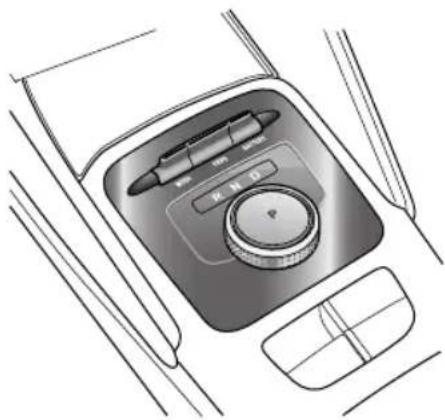
natural_image
Top-down line drawing of a car gear shift control panel with no text or symbolsTheshiftcontrolknobisintheintermediatesteadystate position,andtherearetwounsteadypositionsclockwise andcounterclockwise,thatis,theshiftcontrolknobwill return theintermediatesteadyatposition once released.
STARTING&DRIVING
•PPark
Whentheshiftcontrolknobisinthisposition, the electronicparkingbrakehasbeenapplied. Onlyselect thisgearwhenthevehicleisstationary.
Note: The electronic parking brakesystem must be released via the EPB switch. See "Electronic Parking Brake (EPB)" under the "Brake System" section.
Note: If the electronic parkingsystem fails to activate, the vehicle will enable the parking function of the electric drivetrain transmission, the geaindication shift control knob will flash. Operating the shift control knob to select any other gear Willex Park.
The shift control knob ispressed select and engageP.
If the START/STOP switch is operated top power the vehicle OFF will automatically be selected and engaged.
If the park peda released, the drives eabelt is fastened and driven out per vill automatically beselected and engaged.
•RReverse
Select this gear only when the vehicle is stationary and you wish to drive backwards.
Applybrakpedaturthshiftontrdknob counterclockwisethendndeleasThspring loadedshiftcontrolknobwillreturntoacentral positionandthevehiclewillenterReverse.
•NNeutral
Select the vehicle legislation (for example, waiting for traffic lights).
WheninPark, applythebrakepedal, turntheshift controlknoblockwiseorcounterclockwisetthe firstnon-steadystatepositionandreleasThespring loadedshiftcontrolknobwillreturntoacentral positionandthevehiclewillenterNeutral.
Reverseurtheshifcontrdknoblockwistothefirstnon-steadytatepositionandlease. The
STARTING&DRIVING
springloadedshiftcontrolknobwillreturntoacentral positionandthevehiclewillenterNeutral.
WhilstDisselected,turntheshiftcontrolknob counterclockwisetothefirstnon-steadystateposition andrelease. Thespringloadedshiftcontrolknobwill returntoacentralpositionandthevehiclewillenter Neutral.
- DDrive
Thisisusedfornormaldriving.
WhilstinPark,applythebrakepedal,turntheshift controlknobclockwisetotheendandrelease.The springloadedshiftcontrolknobwillreturntoacentral positionandthevehiclewillenterDrive.
InRorN,turntheshiftcontrolknobclockwisetothe endandrelease. Thespringloadedshiftcontrolknob willreturntoacentralpositionandthevehiclewillenter Drive.
Whenthevehicleisstationaryandhasremainedin Neutralformorethan2seconds.Pleaseapplythebrake pedal,turntheshiftcontrolknobclockwisetotheend andrelease.Thespringloadedshiftcontrolknobwill
returntoacentralpositionandthevehiclewillenter Drive.
ForsafetyreasonsALWAYSapplythebrakepedal whenshiftingbetweenRandDpositions.
DrivingonHills

Incaseswhereashortstoponahillis required,suchasatrafficjam,DONOT frequentlyapplytheacceleratorpedalto preventa"rollback".Thiscouldcausethe electricdrivetransmissiontooverheator evensystemdamage.
HillStart
Incasesofahillstart,thestartassistfunctionofthe electronicparkingbrake(EPB)canbeusedtopreventthe vehiclefromrollingbackwards.Fordetailsonthisfunction, pleasereferto"ElectronicParkingBrake(EPB)"inthe "BrakeSystem"section.
ModelsequippedwithHillHoldControlcanusethis functiontoassisthillstarts.Fordetailsonthehillhold controlsystem,pleasereferto"HillHoldControl"in "BrakeSystem"section.
Note: Theaidofthesefunctionscannotdefythe lawsofphysics.DONOTdrivethevehiclebeyondits physicallimitations.Lossofcontrolwillstilloccur.
DrivingMode

Please avoid switching between Driving Modes while driving this may divert the driver's attention away from road conditions and cause an accident.
Ineachofthedifferentdrivingmodes,thecontrolsystem usesdifferentcontrolstrategiesforoutputcontrol.
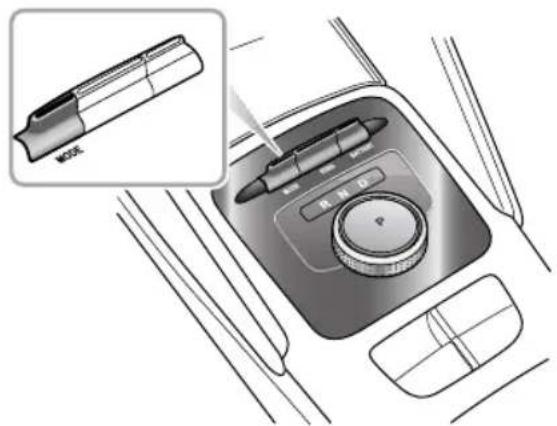
text_image
Diagram showing a device's internal components with a magnified inset of the main panel, labeled 'MOS' and 'MND'.STARTING&DRIVING
Thedrivercanselectthreedrivingmodesbyoperatingthe
MODEswitch:
IECOMode
The vehicle is in the state of flow energy consumption, which is used for energy-saving driving.
2NORMALMode
The vehicle is balanced for daily driving.
3SPORTMode
SportModeconcentratesonprovidingmorepowerto enhancetheperformance.
ConstantuseofSportModewillincreaseenergy consumption.
It is recommended to choose the Sport Mod when driving on special road conditions such as mountain roads.
Whenthedrivingmodeisswitched, themessagecentre will display: ECO, NORMAL, SPORT.
Everytimethevehiclepowersystemiscycledandthe systemsettoREADY ,thedrivingmodedefaultstothe NORMALMode.
Selectingdifferentdrivingmodeswillalsoautomatically selectthesettingsothersystemssuchaselectronic steeringandA/C-pleaseseethechartbelow:
| Driving Mode | Power Mode | Steering Mode | A/C Mode |
| ECO | EcoUrban | Eco | |
| NORMAL | Normal | Normal | |
| SPORT | Dynamic | Sport |
NotWhileECOModeisselectedheA/Cwill operateinalowenergyconsumptionstatetoprovide anincreaseinvehiclepower.
EnergyRegeneration

Decelerationcausedbyenergyregeneration isNOTasubstituteforbrakingsafely. The drivermustALWAYSbepreparedtomake brakingmanoeuvrestomaintainsafedriving.
Whenthevehicleisinabraking,over-runorcoasting state,theenergyregenerationfunctionisactivated,and themotorconvertspartofthekineticenergyofthevehicle intoelectricenergy,whichisthenstoredinthehighvoltage batterypack.
Energy cannot be generated or is limited undersome conditions, such as:
• Ngearisselected(DuringdrivingdonotcoastinN gear);
• During torque intervention (SCSorption control operation);
• Highvoltagebatterypackisfullycharged;
• Highvoltagebatterypacktemperatureistoohighor toolow.
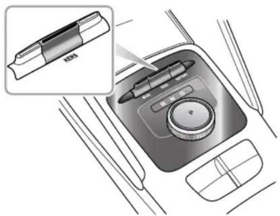
text_image
KBSThe driver can select three energy regeneration levels by operating the KERS switch:
I Heavy
HeavyLevel:Maximumenergyisregenerated,the vehicleexhibitsshortercoastingdistancesandastrong sensationofover-rundragormotorbraking.The messagecentredisplays ③.
2Moderate
STARTING&DRIVING
ModerateLevel: Moderateenergyregenerated. The messagecentredisplays ②.
3Light
LightLevel: Minimumenergyisregenerated, the vehicleexhibitslongercoastingdistancesandno significantssensationofover-rundragormotor braking. Themessagecentredisplays ① .
Everytimethevehiclepowersystemiscycledandthe systemissettoREADY ,theenergyregenerationlevel defaultstotheHeavyLevel.
Note: It is recommended to choose Lightor Moderate level on surface that have low adhesion levels (e.g. icy roads).
EnergyManagement
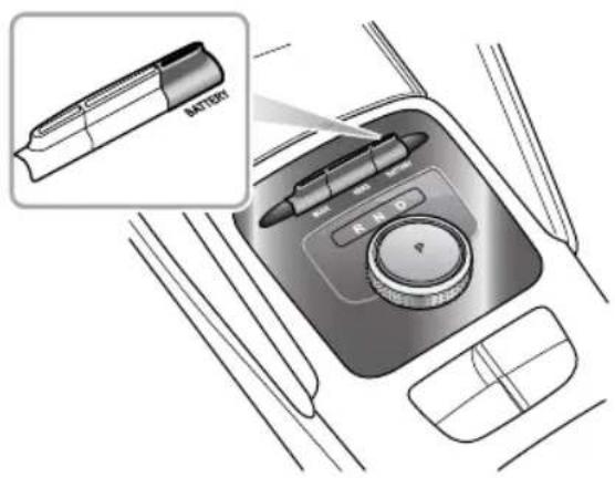
text_image
BATTERYThe driver can operate the BATTERY switch backward to display the energy management interface in the infotainment system.
ProtectionMode

When parking the vehicle, please ensure the vehicle is sparked safely and that all traffic by-laws are observed.
MotorOverheatingProtectionfortheElectric
DriveT transmission
The electric drivetransmission may become every hot in a high-temperature environment with frequent starting, frequent rapid acceleration and deceleration, long-term continuous steep climbing, and overload of the electric drivetransmission. In order to prevent damage to the motor, the system will perform an overheating protection function, the warning message "Motor Overheating" displays.
Inthiscase, park your vehicles safely or , while keeping a low load, continuet drive your vehicle at a constants speed to cool themotor. Only when the motortemperature has decreased, and the warning messaged disappears, can the vehicle bedriven normally.
If the electric drivetransmission has cooled down for a longtime (about 20 minutes) and the warning message has not disappeared, please park the vehicles safely and seek an MGA authorised Repairer immediately. Otherwise it may seriously damage the electric drivetransmission.
IMPORTANT
When the motor of the electric drivetransmission is under heating protection, it would damage to the motor, the power of the vehicle will limit the message centre display power. Limited limiting speed and warning indicator will illuminate). After decelerating, the warnings will disappear whether temperature returns normal.

MotorFaultofElectricDriveTransmission
Ifafaultorfailureisdetectedinthemotororthepower electronicboxofelectricdrivetransmission,thewarning message"MotorFaulConsultHandbook"willdisplay simultaneously.PleaseseekanMGAuthorisedRepairer immediately.
STARTING&DRIVING
ParkingSystemFaultofElectricDrive
T transmission
Ifafaultorfailureisdetectedintheelectricalparkmotor controlunit,thewarningindicatorwillilluminate, andthewarningmessage"ParkingSystemFault,Consult Handbook"willdisplaysimultaneously.Afterafew seconds,thewarningmessagewilldisappearbutthe warningindicator willremainon,pleaseseekanMG AuthorisedRepairerimmediately.
ElectricDriveT transmissionFault
Insomecases,whenafaultorfailureisdetected,the warningdivillominatyellowed accordingdifferentfaultandwarningmessage
"VehicleControlSystemFault, PleaseaskServingStation forHelp!" or "VehicleControlSystemFault, Pleasedrive carefully!" will display simultaneously after few seconds, the warning message will disappear but the warning indicator will remain on.
Isomeases the electric driver transmission will enter Limp Mode and Wilbly function at certain speeds please seek an MGA authorised Repairer immediately.
SevereFunctionalMalfunction
In some cases when a faultorse severe failure is detected in the electric drivetransmission, the warning indicator
willilluminateinreadthewarningmessage "VehicleControlSystemFault,PleaseStopSafely!" will displaysimultaneously. Afterafewsecondshewarning messagewilldisappearbutthewarningindicator will remainon. T oprotecttheelectricdrivetransmission,the powersystemwillsolatepowertransmissionandhe vehiclewillnotbabletobedriven,pleaseseekanMG AuthorisedRepairerimmediately.
In some cases when a fault or severe failure is detected in the system the message centre will display
"Efforsafetyreasons,ifthevehiclespeedisbelow apresetspeed,thepowersystemwillisolatethepower transmissionandthevehiclewilhobabledriven, pleaseseekanMGAuthorisedRepairerimmediately.
BrakeSystem
Thefreestrokeofbrakepedalis0–30mm.
Drivingthroughwaterorheavyrainmayadverselyaffect brakingefficiency.TheSCS(StabilityControlSystem) includesaBrakeDiscWipingfunctionwhichisactivated whentewindscreenwipersareused.However,always keepsafedistancefromothervehiclesandintermittently applythebrakepedalinconditionswherethewipersare notused.
Thebrakesystemisservoassisted,alwaysbeawareofthe followingsduringtheoperation:
- Theservoassistancefunctionisreliantuponvacuum, thisisonlyproducedwhilstthevehiclepowersystemis ONorREADY .NEVERallowthecartocoastwhenthe vehiclepowersystemisOFF .
•Vacuumtosupportthesystemisprovidedbyan electricvacuumpump.DONOTcontinuallypumpthe brakepedal, this may affect the vacuum pump efficiency, the brakesystem maybe unable to provide sufficient brake assist and the vehicles speed will be limited. This situation does occur or is unavoidable, when it is
safetodoso,pleasepulloverandallowtheelectric vacuumpumptocooldownforawhile.Pleasepower thevehicleagain,toreturntonormal.
the prom p messageVacuusystemfaults displayedintheinstrumentpack,bringthecartoahalt asquicklyastrfficconditionssafelyallowandcontact anMGAuthorisedRepairerassoonaspossibleAt thistime,thebrakesystemmaybeunabletoprovide sufficientbrakingforce,DONOTdrivethevehicle.
•Theefficiencyofthebrakeservoboostercanbe affectedbynumerousconditionsuchaschangeof atmosphericpressureduetaltitudedifferences. These conditionscouldresultinextraforcebeingrequiredto operatethebrakepedaltostopthecar.
ElectronicBrakeForceDistribution(EBD)
You equipped ElectronBrallForce
Distribution, which, inordertomaintainbrakingefficiency, distributesbrakingforcesbetweenfrontandrearwheels, underallloadconditions.
STARTING&DRIVING
ElectronicBrakeAssistance(EBA)
Y ourcarisequippedwithElectronicBrakeAssistance, whichreactstothespeedatwhichthebrakepedalis applied. If, inanemergencysituationthebrakesareapplied faster thanthelimitssetwithinthesystem, then fullABS applicationisapplied to bring the cartoastopin the shortest possible distance.
Anti-lockBrakeSystem(ABS)

Whentravellingathighspeedorthereisa dangerofaquaplaning,i.e.wherealayer ofwaterpreventsadequatecontactbetween thetyresandtheroadsurface,ABScannot overcomethephysicallimitationsofstopping thecarinashortdistance.Inthesecases,it istheresponsibilityofthedrivertomaintain asafedistancefromothervehicles.

DONOTpumpthebrakepedalatanytime, thiswillinterrupttheoperationofABSand mayincreasethebrakingdistance.
ABScanpreventthewheelsfromlockingwhilebraking, therebyenablingthedrivertoretainsteeringcontrolof thecar.
Undernormalbrakingconditions, ABSwillnotbe activated. However , oncethebrakingforceexceedsthe availableadhesionbetweenthetyresandtheroadsurface, therebycausingthewheelstolock, ABSwillautomatically comeintooperation. Thiswillberecognisablebyarapid pulsationfeltthroughthebrakepedal.
Ifanemergencysituationoccurs, the drivers should apply full braking effort to activate ABSevenwhenteroad surface is slippery.
Not Onsoftsurfacesuchaspowderysnow,sand orgrave vehiclesequippedwitABSmayhavea brakingdistancegreaterthanthosewithoutABS.This is because then natural action of locked wheelson soft surfacesist buildupawedge of material in front of (ortothesideof,ifsteering)thetyrecontact patch. This effect assist the cart stop when braking to changed direction when steering.
STARTING&DRIVING
IMPORTANT
ABScannotreliablymakeupforthedriver's misoperationorlackofexperience.
HillHoldControl(HHC)

HHChaslimitationswhensubjecttoadverse conditionssuchaswetoricysurfacesand steepslopes.

DONOTexitthevehiclewithonlyHHC applied, it may lead to as serious accident when HHCreleases.

Firmapplicationofthebrakepedalwhen stoppingisrequiredbyHHCtogenerate sufficientbrakepressureotmaintainhold.
HHCassiststhedriverby'holding'thevehicleduringhill starts. Ifthedriverreleasesthebrakepedal, the HHCwill holdthevehiclestationaryforashorttime.
The following conditions must be fulfilled to activate HHC:
- Thedriver'sdoorisclosedandthedriverseatbeltis fastened.
•Thevehicleisstoppedonaslopeformorethan2 seconds.
•SCSisactiveandfaultfree.
•EPBisfaultfreeandreleased.
•PowersystemisREADY .
•DorRgearisselected. - Sufficientbrakepedalapplicationforcehasbeenapplied.
Note: HHCisavailableinbothforwardandbackward directionswhenpullingawayonuphillslopes.
STARTING&DRIVING
HillDescentControl(HDC)
TheHDCsystemisonlyanauxiliary function. Ithaslimitationswhensubjectto adverseconditionssuchaswetoricysurfaces andsteepslopes.
EvenwhenHDCsystemisswitchedon, the drivermustalwayspaycloseattention to the drivingstateofthevehicle, and take activecontrolwhennecessary. In certain cases, HDCmaybesuspendedorswitched off temporarily.
Duringsomedrivingconditionsdownhill surfaces(driguingdownslope highspeedorsmaslope,etc.),HDG inoperative,thedrivermustmaintaincontrol ofthevehicleataltimesndusbrake applicationstoensuresafety.


The HDC system is an auxiliary functions specially designed for driving cut down high gradient system reduces the speed by applying brake force, thus assisting
thedrivertodriveonacutedownhillsurfacesatlow speed.
Note: When HDC system is working, the brakesystem will produce slight vibration or working noise, which is anormal phenomenon.
Note: During the operation of the HDC system, please do not movetheshift control knob to the "N" position. Such operation may deactivate the HDC function.
HDCSystemOn/Off
WhentheSTART/STOPSwitchisswitchedtoON/READ Y, theHDCsystemdefaultstooff.UsetheswitchwithintheinfotainmentsystemtoturntheHDCsystemon/off.
TheHDCsystemhasfourstates:
Standby: PresstheHDCswitchtosetthesysteminto standbymode, thegreenHDCindicatorlampinthe instrumentpackwillilluminate.
OperationwhilstinStandbymode: Whenthevehicle drivesontoasteepslopeatalowspeedandthedriver doesnotpressthebrakeandacceleratorpedal, the
systemwillautomaticallyentertheoperatingstate.In thiscase,theHDCindicatorlampintheinstrument packflashesgreen,thismaybeaccompaniedbythe workingnoiseofthebrakesystem.TheHDCsystem willattempttocontrolthevehicle'sdescentdownthe steepslopesmoothly.
3T emporaryDeactivation: Bypassingtheaccelerator pedalorifthebrakepedalispressedbeyondacertain limitwhilstinoperatingmode, theHDCsystemwill temporarilysuspendoperation.
4Off:PresstheHDCswitchagaintoswitchthesystem off,thegreenHDCindicatorlampintheinstrument packwillextinguish.
Note: If the vehicle undergoes sharp steering manoeuvresoncertaingradients the HDC system may change from the stand by state to the operating state.
Note During HD System operation, the brake system will automatically pressurise and maintain pressure. Operation of the brake pedal during this phase may
resultina'kickback'sensationthroughthepedal. This isanormalphenomenon.
AutoHold

TheAutoHoldfunctioncannotguarantee thestabilityofthevehiclewhenstartingoff orbrakingonhillsespeciallyonslipperyor icysurfaces.

Whetuddoldthehicfor reasonssuchaspowersystemshutdown, releasingtheseatbeltorpressingtheAuto Holdswitch,theelectronicparkingbrakeis applied.Itcannotbeguaranteedthatthe vehiclewillbestabilisedinallcasFor example,therearwheelsareonaslippery roadurfacethehiclinclinoogreaPleasemakesurethatthevehicleis safelystabilisedpriortoexiting.

The drive should pafullattention and observethesurroundingsevenifthevehicle is equipped with AutoHoldsystem.
STARTING&DRIVING

AutoHold cannot guarantee the electronic parking brake operation in all cases where the powersystem is shut down. Please ensure the electronic parking brake is applied and the vehicle is stabilised prior to exiting the vehicle.

TheAutoHoldfunctionsshouldbeswitched offduringtheuseofautomaticcarwashes, otherwisetheelectronicparkingbrakemay suddenlyapplyandcausevehicledamage.
If the vehicle is required to stop frequently for a length of time (such as traffic lights, traffic queues or stops / start), and the powers system is running, the Auto Holds system consists instabilising the vehicle, enabling you to remove your foot from the brake pedal when the vehicle is stationary and the Auto Hold active.
AutoHoldhas3mainstates:
I Standby:
Withthedriver'sseatbeltfastened,thedriver'sdoor closedandthepowersystemrunning,pressthe AutoHoldswitchtoswitchthefunctionfromOffto
Standbystate.TheAutoHoldswitchindicatorlamp illuminates.
2Parking:
Withthebrakepedalfirmlypressedandthevehicle completelystopped,theAutoHoldfunctionwill switchfromStandbystatetoParkingstatethis statethegreenindicator (P) ontheinstrumentpack illuminates.
WhentheAutoHoldisintheParkingstate,engaging forwardorreversegearandpressingtheaccelerator pedalwillautomaticallyreleasetheAutold function.
3Off:
PresstheAutoHoldswitchagaintoturnthefunction off.
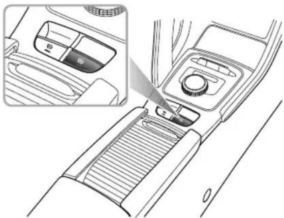
natural_image
Line drawing of a car interior showing the dashboard and side panel with a control knob (no text or symbols)Insomecircumstancesuchasreleasingtheseatbelt, switchingoffthepowersystemorremainingstaticfor alengthoftime,itwillresultinexitingtheAutoHold Parkingstate.Atthistimethelectronicparkingbrake willbeapplied.
Note: The parking brakewill NOT be applied when operating the switch to turn the Auto Holdoff with the brake pedal pressed.
Note: It is recommended to turn off the AutoHold function when reversing into the garage.
ActiveRolloverProtection(ARP)
The ARP system is a driver aid to assist the stability of the vehicle under extreme conditions. It is not guaranteed that the car will not rollover.
Incaseswherethevehiclehasahighcentreofmass,rapid orexcessivedualdirectionlanechangingmaycreatea rollcondition.ARPmayusethebrakesystemtoapply certainbrakestotryandcorrecttheconditionandassist inpreventingrollover.
NoteA: Application steering characteristics of the vehicle may be noticeably different from normal.
EmergencyBrakingHazardWarningLights Control(HAZ)
Whenthevehicleisdrivingathighspeed,ifthedriver makesanemergencybrakingmanoeuvre,thebrakelamps willautomaticallyflashtoalertthedriversbehind.
STARTING&DRIVING
Note: If the hazard warning lamps are being operated manually, this suspend the HAZ function.
Whentheemergencybrakingmanoeuvreisexited(no severedecelerationdetected)thenthefunctionwillbe switchedoffafterafewseconds.
Note: Asthecarspeeddropstobelow6mph(10km/h) andthebrakelampsnolongerflash, thehazard warninglampswillilluminateautomatically. Short pressthehazardwarninglampswitchorincrease yourspeedtoabove12mph(20km/h)for5secondsto switchoffthehazardwarninglamps.
Multi-CollisionBrakeSystem(MCB)
TheMCBfunctionwillautomaticallyapplythebraketo reducethevehiclespeedandimprovethevehiclestability afteracollision.Itisdesignedtoreducetheriskofa secondarycollisioncausedbytheuncontrolledmovement ofthevehicleafteracollision.
TheMCBwillbeactivatedwhenthefollowingconditions areallmetatthesametime:
- Avehiclecollisionwhereseatbeltsorairbagsare deployed;
•Thevehiclespeedislessthan37.5mph(60km/h); - Thesteeringwheelhasnotbeenturnedinexcessof 180^ ;
•SCSisfaultfree.
AfteracollisionortheMCBfunctionistriggered,ifthe driverstronglyappliestheacceleratorpedal,thesystem willnottriggerorexitthebrakingstate.
NothMCFunction can not decelerate the vehicleinal cases of collision, because the collision process may cause some part stomal function or fail and affect then normal operation of the function.
StabilityControlSystemandT raction ControlSystem
StabilityControlSystem(SCS)
SCSisdesignedtoassistthedriverincontrolofdriving direction.
WhenSCSdetectsthatthevehicleisnotmovinginthe intendeddirection,itwillintervenebyapplyingbrake forcetoselectedwheelsorthroughthepowersystem managementsystemtopreventslidingandassistinbringing thecarbacktotherightdirection.
T ractionControlSystem(TCS)
The purpose of TCSistoaid traction, thereby helping the drivertomaintain control of the car insituations where one or both of the driving wheels are spinning (forexample, if onewheelisonice and the other ontarmac).
TCSmonitorsthedrivingspeedofeachwheelindividually. Ifspinisdetectedononewheel,thesystemautomatically brakesthatwheel,transferringtonquetotheopposite, non-spinningwheel.Ifbothwheelspinning,the
systemwilleducmotopoweinddetrogulate wheelrotationuntiltractionisregained.
SwitchingOn/Off
SCSandTCSareautomaticallyswitchedtostandbywhen thepowersystemplacedinON/READYposition,they canbeswitchedoffbyusingtheswitchlocatedwithinthe infotainmentsystemwhenthepowersystemisinREAD Y mode.
NotDisablingSCSandTCSwillnotaffectthe operationofABS.AlwaysdisableSCSandTCSwhen drivingwithsnowchainsfitted.
STARTING&DRIVING
ElectronicParkingBrake(EPB)

IntheeventofEPBmalfunctionwhereEPB releaseisnotpossible,pleaseconsultanMG AuthorisedRepairerinordertocarryoutan emergencymanualreleaseoftheparking brake.
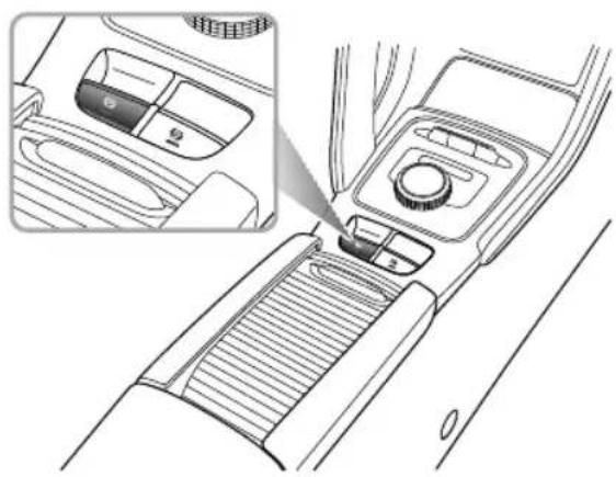
natural_image
Line drawing of a car interior showing the dashboard and seatbelt with a close-up inset (no text or symbols)ApplyingEPB
Whenthevehicleisparkedsafely,selectingPontheshift controlknobwillautomaticallyapplytheEPB.IftheEPB cannotbeactivatedautomatically,pleaseactivatetheEPB manuallyasfollowsbeforeleavingthevehicleorparking.
• PulltheEPBswitchupwarduntiltheindicatorintheEPB switchilluminates.
- If the indicator in the EPB switch and the indicator in the instrument packilluminate, the EPB is applied.
Note: Anaudiblemotornoisemaybeheardwhen applyingorreleasingEPB.
IMPORTANT
•DONOTleavethevehiclebeforetheindicatorin EPBswitchilluminatesandthegearindicatordisplays P ,thevehiclemaynotbesafelyparkedduetoEPB failureandslip.
• Intheeventofaflatbatteryorpowerfailureitis notpossibletoapplyorreasetheEPB.Ifusing 'jumpleads'totemporarilysupplypowerpleaseesee 'EmergencyStarting'intheEmergencyInformation.
ReleasingEPB
Ifthevehicleisstablyparkedonaflatroadorslight incline/decline,thevehiclepowersystemisREADY ,press thebrakepedaltoallowtheshiftcontrolsystemtoswitch fromPtoN,DorR,theEPBwillautomaticallyreleased.
Ifonasteepslope, switching from the P position will not automatically release the EPB. In this case, manually release the EP Bas follows or apply the Start Assist function of the EP B to release the EPB.
- Ensurethevehiclepowersystemissettothe ON/READYposition,pressthebrakepedal,andpress theEPBswitch.
• If the indicator in the EPB switch and the indicator (P) in the instrument pack are extinguished, the EPB is released.
StartAssist
TheEPBcanpredictthedriver'sintentionand automaticallyrelease.
Ifthedriver'sseatbeltisfastened, thepowersystemis READY , DorRgearisselectedandtheacceleratorpedal
ispressedinordertopullaway,theEPBwillautomatically release.
EmergencyBrakingFunction

Inappropriate EPB load accidents and injuries. Donot apply the EPB for vehicle braking unless in emergency.

During emergency braking using the EPB, DO NOT switch the START/STOP switch, this could result in serious injury.
Intheeventofnormalbrakefailure emergencybraking usingtheEPBcanbeinitiatedbypullingandholdingthe EPBswitchupward.
• PulltheEPBswitchupwardandoldtoealisethe emergencyrakingprocessemergency braking,anaudiblewarningwillsoundatthesametime.
- T ocanceltheemergencybrakingprocess,releasethe EPBswitch.
STARTING&DRIVING
AdaptiveCruiseControlSystem

Theadaptivecruisecontrolsystemis designed as comfort systemenabling the drivertomaintain a constantspeedor distance from the carin front. It provides assistance to the driver, it DOES NOT replace any of the drivers responsibilities. When using the adaptive cruise control system, its important that the driver maintains concentration at all times and is prepared to take action otherwise, accidents or personal injuries may occur.
The adaptive cruise control system can automatically switch between constant speed and following cruise depending on whether to detect vehicles directly ahead. Constants speed control vehicle within certain speed range, following cruise operate by setting the distance between vehicle and vehicle directly ahead.
When activated if the adaptive cruise control system detect vehicle, he is directly headway
accelerately apply the brakes of the cart maintain the following distance.
NoteThe adaptive cruise control system designed for highways and road conditions recommended not to be used on urban roads and mountain roads.
Adaptive Cruise Control System Activation

Aftefollowingthevehicleaheadatop, therivemusobservanyocatraffidaws andensurethattherearenoobstaclesor othetraffic participantssuchspedestrians, directlyinfrontofthevehiclebeforallowing itopulbwayandbegintofollowthevehicle aheadgain.

Whilst using the following cruise function it is strongly recommended that the driver does not touch the accelerator pedal. Any activation of the accelerator will not allow the system automatically apply the brakes should be necessary.
STARTING&DRIVING

DONOTexitthevehiclewhentheadaptive cruisecontrolsystemcarfollowingcruise functionhasstoppedthecar,oriskeeping thecarstationary.Beforeexitingthecar theshiftcontrolknobshouldbeinthePark positionandtheSTART/STOPSwitchinthe OFFposition.

If the adaptive cruise control system has already stopped the vehicle, and the adaptive cruise control function is disabled, turned off or cancelled, the vehicle will no longer stay still, it may move forward or slip backward. When the vehicle is stopped and kept still by the adaptive cruise control system, besure to be ready to apply the brakes manually.

Whendrivingonabend, the adaptive cruise control may actively reduce the vehicles speed to maintain vehicle stability and safety.
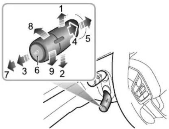
text_image
Diagram showing a car interior with numbered components and directional arrows indicating motion or movement, including a magnified view of the component.ISpeedLimitIncrease/Accelerate
2SpeedLimitDecrease/Decelerate
3Cancel
4Standby
5Resume
Slet
OFF
STARTING&DRIVING
8IncreaseDistance
9DecreaseDistance
Theadaptivecruisecontrolsystemisoperatedwithalever switch,whichislocated,attheleftsideofthesteering wheelunderneaththeindicator/lightingstalkswitch.
IWiththevehicleSTART/STOPSwitchinthe ON/READYposition,iftheadaptivecruiselever switchisinthe'OFF'position(7),thentheadaptive cruisecontrolsystemisswitchedOFF.
2Movetheadaptivecruiseleverswitchtothe'ON' position(4),theadaptivecruisesystemstatusindicator ontheinstrumentpackilluminatesyellow,theadaptive cruisecontrolsystemisintheStandbymode.
3 Thesystemwillautomaticallydetectthespeed and positionofthevehicleahead, ifyourvehiclespeed abovemph( &m/h )afterpressingSet' button(6)attheendoftheadaptivecruisestalklever, theindicatorontheinstrumentpackwillturngreen, andadaptiveruiscontrolsterenterhe Activatedmode,ittargetspeedistheactualspeed atactivation;ifyourvehiclespeedislessthan20mph
(30km/h), thenthetargetspeedofthesystemis sea20mph(30km/h) If the speed of the vehicle ahead is greater than the cruisetargetspeed of your vehicle, your vehicle will maintain the targets speed to conduct constants speed cruise. If the speed of the vehicle ahead is slower than the cruisetargetspeed of your vehicle, it will enter the car - following cruise. An image of your car and the car ahead is displayed in the instrument pack message centre. In this mode the actualspeed maybe less than these target speed.
Whilst the following amusement can follow the vehicle ahead to stop. If the parking time is less than a preset time period, your vehicle may automatically pull away to follow the vehicle ahead, or you need re-activate adaptive cruise control system using themethod displayed.
NotManuadeactivationfitherethEraction
ControlSystem(TCS)StabilityControlSystem
(SCS)willinhibittheoperationoftheadaptivecruise controlsystem.
AdaptiveCruiseTargetSpeedAdjustment
Whentheadaptivecruisecontrolsystemisactivated:
I Use the accelerator pedal to reach the desired speed, short press the 'Set' button (6) on the end of the adaptive cruises switch lever, releasethe control button and accelerator pedal. The vehicle will cruise at the desired speed.
2Movetheleverswitchupward(I)andhold,thetarget speedwillincreaseuntilthedesiredsetspeedappears intheinstrumentpack,thenreleasetheswitch.When itisconfirmedthatthereisnovehicleinfrontofyour vehicleorthevehicleaheadexceedsthepreselected followingdistance,thespeedwillbeincreasedtothe setspeed.
3Movetheleverswitchdownward(2)andhold,the targetspeedwilldecreaseuntilthedesiredsetspeed appearsintheinstrumentpack,thenreleasethe switchthevehiclespeedwidearestset speed.
4Whenusingthelevertoadjustthetargetspeed,briefly operattheadaptivecruiseleverswitchupward(1)
ordownward(2)once,thetargetspeedwillchange 5mph(5km/h)pressandholdtheveupwardor downwardandthespeedwillincreaseordecreasein 1mph(km/h)incrementsreleasethevewhen thedesiredspeedreadingisdisplayed.
Note: If the vehicle ahead continually makes hard acceleration or deceleration manoeuvresthead adaptive cruise control may not be able accurately maintain the required distance between vehicles is important that the driver always concentrates and pay attention to the current vehicle position and situation in case they need to make abraking or avoid ance manoeuvre.
AdaptivCruiseTargeFollowingDistance Adjustment
Whether adaptive control system activated, rotate the switch through the overlap (B) or downward (9) to adjust the following distance, you are able to toggle between 3 distances settings which are displayed in the message centre in the instrument pack.
Always select appropriate following distance that relative the current speed of fourEHIClanthe
STARTING&DRIVING
vehicleyouarefollowing,thegreaterthespeed,the furtherthedistance.ALWAYSconsidercurrenttraffic, roadandweatherconditionswhenmakingyourselection.
AdaptiveCruisePause/Standby
Whentheadaptivecruisecontrolsystemisactivated,move theleverswitchtothe'Cancel'position(3),andthesystem willexittotheStandbymode.
AutomaticDeactivationofAdaptiveCruise
In the following situations, the adaptive cruise control system may be automatically deactivated, this transfers full control of the vehicle to the driver.
- Movetheleverswitchto'OFF'position(7).
•Pressthebrakepedalwhilstthevehicleisinmotion. - MovetherotarygearknobtoeitherRorNposition.
• Thedriverunfastenshis/herseatbelt. - Pressandholdtheacceleratorpedalbeyondapreset timeperiod.
-
Openanydoor, bonnetortailgate.
• PulltheEPBswitchuptoapplytheparkingbrake. -
Followthevehicleaheadtoastopandthestoptime exceedsacertainperiodoftime.
- Thecameraorradarviewisblocked,thesurrounding environmenttriggersthepresetsafeexitmechanismof thesensors,orthesystemfails.
Note: Iffollowingthevehicleaheadtoastopwith theadaptivecruisecontrolsystemenabled, if any of the following conditions occur whilst the vehicle is in a stopped state, the EPB will automatically be applied:
• Thedriverunfastenshis/herseatbelt.
• Thedriverdoorisopened. - Thestationarytimeexceedsthepresettimeperiod.
AdaptiveCruiseOverride
If the driver has a cause to set the accelerator pedal when the adaptive cruise control system is activated, the vehicle will remain in Cruis mode while the vehicles speed increases. When the accelerator pedal is released, the adaptive cruise control system will resum to operate at previously set cruises speed.
AdaptiveCruiseResume
If the adaptive cruise control system has reverted to, or beenswitched to, the Standbymodeit can be reactivated by moving the leverswitch to the Resume position (5). The target cruises speed will automatically be set to the targetspeed before exiting the adaptive cruise control system.
ClearSpeedMemory
If the leverswitch is moved to the 'OFF' position (7) or the vehicle ST ART/STOPS switch is switched to the OFF position, the system may clear the adaptive cruise control sets speed in the memory.
AdaptiveCruiseControlSystemImpairment and Ineffectiveness
- Encountersavehicleorobjectwhichisstationaryor traversingthelanes.
-
Approaching the vehicle ahead to fast, and the system cannot apply sufficient braking force.
•Thevehicleaheadisanoncomingvehicle,ormakesan emergencybrakingmanoeuvre. -
Avehiclesuddenlycutsintothelaneinfront.
- Encountersavehicledrivingatalowspeed.
- Encountersavehiclewithloadeditemsprotrudingfrom thebodyprofileofthevehicle.
- Encountersvehiclewithahigherchassis(e.g.,atruck).
- Encounterspedestrians, non-motorvehicles or animals.
• The vehicle is driving on an uneven road or a complex traffic road section.
•Thevehiclemakesasharpturn. - Entersandleavesatunnelordrivesinthetunnel.
• Drivesintheshadeofmottledtrees. - Excessiveweightbeingcarriedinthebootspaceor cargoareacausingthefrontofthecartopointupwards.
SpecialDrivingEnvironments
The adaptive cruise control system has its limitations. Listed below a some condition that maybe beyond the safe operating limits. The drivers should maintain control of the vehicle and must remain alert at all times. They should pay special attention to the traffic conditions and surroundings, select the appropriates speed and beready to take any required actions.
STARTING&DRIVING
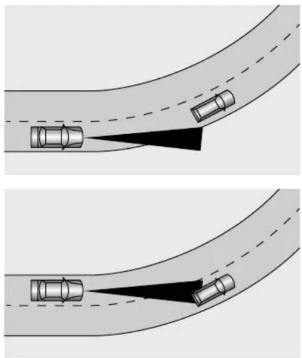
natural_image
Diagram showing two scenarios of a car approaching a curved road, with no text or symbols present.Whenturningatanintersectionorfollowingvehicleinto, oroutofacurve, theadaptivecruisecontrolsystemmay
beunabletodetectthevehicleahead,evenifitisinthe samelane,itispossiblethesystemmaydetectavehiclein anotherlane.
Note: Donotusetheadaptivecruisecontrolsystem onentrance/exitrampsorsharpbends.
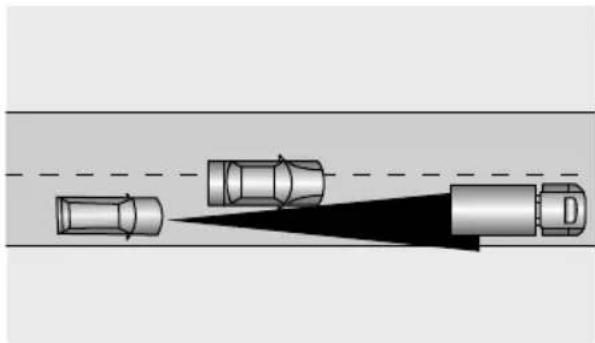
natural_image
Diagram showing three cars approaching a road with a shadow, no text or symbols presentIfthevehicleaheadchangeslanes,butdoesnotdriveinto thelanecompletely,theadaptivecruisecontrolsystemmay beunabletodetectthevehicle.
If the vehicle ahead changes lanes, but does not exit the lane completely, the adaptive cruise control system may
STARTING&DRIVING
determinethatthevehicleaheadhasexitedthelaneand acceleratetoanypresetspeed.
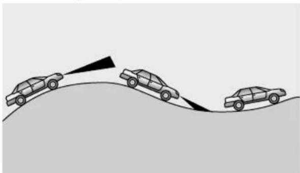
natural_image
Illustration of three cars on a curved surface with directional arrows indicating motion (no text or symbols)Whendrivingonunevenroadsthatmayincludesteep climbsordipspleaseDONOTusetheadaptivecruise controlsystem.
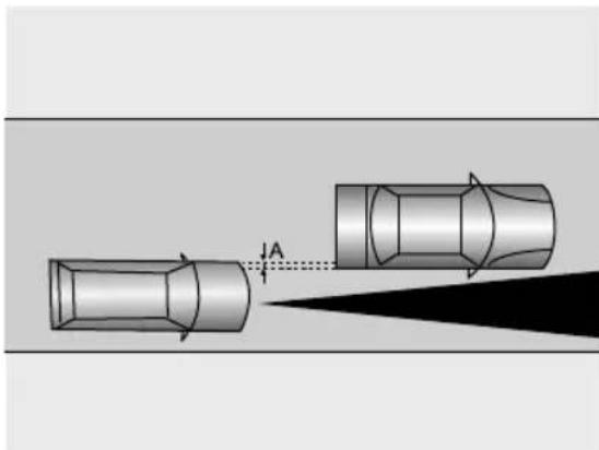
natural_image
Diagram showing two cars with directional arrows and a labeled point A, no text or symbols presentWhendrivingbehindavehiclethatisonlypartially overlappingyourvehicle,'A'inthegraphic,theadaptive cruisecontrolsystemmaybeunabletodetectanything.
Note: Please DONOT usetheadaptive cruise control system in the following situations: • Driving in bad weather conditions.
STARTING&DRIVING
- When the ambient light is insufficient, the light is to obright, or the forward lighting of the vehicle is poor.
- Drivingonroughorpoorroadsurfaces.
- Drivingthroughroadworksorconstructionsites.
- Drivingonlowfrictionroads.
ParkingAidSystem
UltrasonicSensorParkingAid

The purpose of the parking aid to assist the driver in reversing! Thesensors may not be able to detect obstacles of certainty, e.g. narrow posts or small objects nom more than afewinches wide, small objects closeto the ground, objects abovethetail gate and some object with non-reflectives surfaces.

Keepthesensorsfreefromdirt,iceandsnow. Ifdepositsbuilduponthesurfaceofthe sensors,theirperformancemaybeimpaired. Whenwashingthecar,avoidaiminghigh pressurewaterjetsdirectlyatthesensors fromcloserange.
RearParkingAid
The ultrasonicsensors in therear bumper monitor the area behind the vehicle to search for obstacles. If any obstacle is detected, the system will calculate its distance from the rear of the vehicle and communicate them message to the driver by sounding warning chimes.
ParkingAidinOperation
Therearparkingaidisenabledautomaticallywhen reverseisselected,itisswitchedoffassoonasreverse isdisengaged.Ashortbeepisgivenbytheparkingaid within l secondafterselectingreversetoindicatethatthe systemisoperatingnormally.
The entertainmentsystemscreenwilldisplayasilhouette imageofthecarshowingtheobjectdistancevaluesforthe sensor.
Note: Ifalonger, higherpitchedsoundisemitted for 3 seconds when reverse is selected this indicates a fault in the system. In this case seek assistance from your MGA authorised Repairer.
STARTING&DRIVING
With the parking aid enabled, when obstacles are detected, the system will give sounds in different frequencies (there might be blind areas).
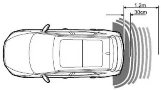
text_image
1.2m 30cm• If thereisanobstacle within 1.2m range from therear sensors, the system start to emit abeepingsound. As the vehicle moves closerto the obstacle, the beeps are transmitted more rapidly.
- Oncetheobstructioniswithin30cmrangeoftherear bumper,thebeepswillmergeintoacontinuouswarning.
360AroundViewSystem

The purpose of the 360 around viewsystem istoassist the driver during parking, The camerashave alimited field of vision and cannot detect obstructions outside the field of vision.

Although the entertainment display can provide images around the vehicle, please still pay attention to the current actual road conditions for your drivings safety.

Pleaseensure that the exterior rear view mirrors are unfolded when using the 360 around viewsystem.
Withthe360aroundviewsystemactivated,the entertainmentdisplayplayDegree panoramicimageofthevehicleofacilitatetheobservation ofthesurroundingenvironmentinordertoassistwith saferdriving.Buttonsontheentertainmentdisplaycanbe touchedtoviewtheimagesfromdifferentanglesaround thevehicle.
The360aroundviewsystemcanbeenabledusingthe followingmethods:
SelectingReversegear.
Operatingthe360button.
Using Setting Interface Level speed switching lights/indicator will automatically open the 360 around view system when the indicators are used at low speeds and exit when the indicators are cancelled.
Inthe360aroundviewsystemdisplayinterface,select thesettingsicontoenablepersonalsettingsforsystem functions.
Note: Whentheshiftleverisplacedinforwardgear position, the 360aroundviewsystemisinhibitedat speedsaboveorequalto 10mph(15km/h).
STARTING&DRIVING
RearDriverAssistanceSystem \*
SystemOverview

Thereardriverassistancesensorsmay misidentifiesomesurroundings,suchas roadsidebuildingsorguardrailsandprovide afalsealarm.

Theeffectiverecognitioncapabilitiesofthe rearsensorscanbelimitedbyobjectssuch asroadsidebuildings, guardrails, changesin pitchangleofthecarduetoheavyloading, roadconditionssuchasbendsorbumpsor weatherconditionssuchassnowandiceetc. Anyoftheabovemaytriggerafalsealarm.

Thesystemhaslimitationsandmaynotbe abletowarnofvehiclesapproachingathigh speeds.

Thereardriverassistancefunctionisonlyan aide,itisNOTasubstitutefortheattention ofthedriver. Thedrivermustalwaysremain incontrol,observethesurroundingsanddrive safely.

Thereardriverassistsystemmaynotprovide adequate warning of very fast approaching vehicles or operate correctly on tight curves of 500 m radius or less.

Thereardriverassistsystemwillnotoperate correctlywhilsttowingatrailerorcaravan.

The correct operation of therearsensors will be compromised if they are misaligned due to accident damage. This may cause the system to automatically shutdown.

Toensure that the radar sensors work correctly there are bumpers should be kept free of snow and ice and must not be covered.

Useofnonrecommendedmaterialsor paintonrearbumperrepairsmayhavea detrimentaleffectontheoperationofthe rearsensors.Pleaseonlyuserecommended materials.
Thereardriverassistancesystemincludesblindspot detection(BSD),lanechangeassist(LCA),andreacross trafficalert(RCTA)functions.
Thereardriverassistancemodulesaremountedatthe rearofthevehicleoneachside,theycanassistindetecting vehiclesbehindortothesideofyourvehicle.
The warning lampstosupport this system are located within the LHandRH doormirroglasses, they will illuminate or flash to warn of an approaching objector car to assist you in manoeuvring the cars safely.
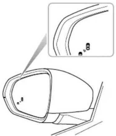
natural_image
Technical line drawing of a car side mirror with an inset showing a close-up detail (no text or symbols)Note: Theradarrequirescalibrationonnewvehicles orforvehiclesofwhereareardetectingradar sensorhasbeenreplaced. Thereardetectionradar sensorspossessanautomaticcalibrationfunctionto compensateforinstallationerrorwithinacertain rangeWhenthevehicleisrunning,theradarwill automaticallyenterthecalibrationstate.Duringthe calibrationprocess,thesystemwillprovidelimited functions,andthealarmmaybeinaccurate.Upon
STARTING&DRIVING
completionofthecalibration, thesystemwillresume allfunctions.
SwitchingtheSystemFunctionsOn/Off
Thereardriverassistsystemfunctionandsubsystem switchescanbeaccessedviatheinfotainmentscreen.
SelectON/OFFtoactivate/deactivatethesystem.
SystemFunctions
Note: Thedetectionarea, collisiontimethreshold value and vehiclespeed provided in the system function description are just for your reference.
BlindSpotDetection(BSD)
Whenthevehicleisdrivingforward,thesystemwill monitorthemotorvehicleslocatedintheblindzonesof theleftandrightexteriormirrors.Whentheconditions foractivatingtheblindspotdetectionfunctionaremet,the warninglampsinthecorrespondingmirrorwillilluminate. Subsequentoperationoftherelevantindicatorwillcause thewarninglampinthemirrortoflashtoremindthe driverofanapproachingvehicle.
STARTING&DRIVING
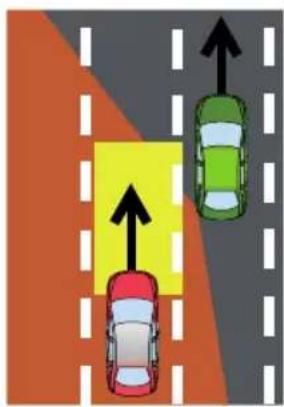
text_image
Diagram showing three cars on a road with directional arrows indicating movement or traffic flowand7mbehindtherearofthevehicle,and3.5mtothe sideofthevehiclearethesystemdetectionareas.
Note: The warning lampswill not to illuminate whilst you are overtaking another vehicle and your speed is greater than that of the vehicle you are passing, even though it is in the blind zone.
The conditions for activating the blind spot detection function include:
INofaultsarepresentinthesystem.
2Blindspotdetection(BSD)functionisenabled.
3Thevehiclespeedisabove10mph(15km/h).
4Therearemotorvehiclesintheblindzoneofthe vehicle. Theleftandrightareas, which are I mahead
STARTING&DRIVING
LaneChangeAssist(LCA)
Whenthevehicleisdrivingforward,thesystemwill monitorthemotorvehiclesapproachingrapidlyinthe adjacentlanes.Whentheindicatorsareactivated,andthe conditionsforactivatingthelanechangeassistfunction aremet,thesystemwillflashtehwarninglampwithinthe respectiveimirrortowarnthedriverofanapproaching vehicle.Thisaimstohelpavoidcollisionswhenchanging lanes.
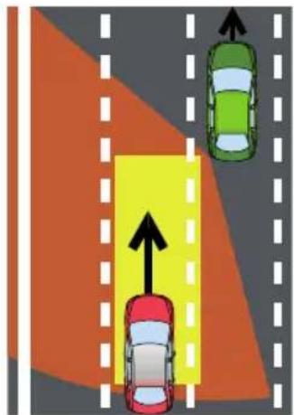
natural_image
Diagram showing three cars on a road with directional arrows indicating movement or flow (no text or symbols)The conditions for activating the lane change assist function include:
INofaultsarepresentinthesystem.
2Lanechangeassist(LCA)functionisenabled.
3Thevehiclespeedisabove10mph(15km/h).
4Thespeedoftheapproachingvehicleishigherthanthe speedofyourvehicle.
5Theapproachingvehicleentersthedetectionareaof thelanechangeassistance,themonitoredareasare 7m-70mbehindyourvehicleand3.5mtothesideof yourvehicle.
6Theapproachingvehicleislikelytohaveacollisionwith yourvehiclewithin3.5seconds.
STARTING&DRIVING
RearCrossT rafficAlert(RCTA)
Whenthevehicleisreversing,thesystemwillmonitor vehiclesapproachingfromtheleftandrightrear.When theconditionsforactivatingRCTAfunctionaremet,the warninglampsinthemirrorsonthecorrespondingside willilluminate,simultaneouslyawarningtriangleiconfor thecorrespondingsidewillbedisplayedintheinfotainment screentoalertthedrivertothesituation.
natural_image
Top-down view of a parking lot with multiple lanes and a central yellow area marked by an arrow (no text or symbols)The conditions for activating there are cross-traffic alert function include:
INofaultsarepresentinthesystem.
2Rearcrosstrafficalert(RCT A)functionisenabled.
3ThevehicleisinReversegear.
4Thevehiclespeedislessthan6mph(10km/h).
5Thespeedofthevehiclebeingmonitoredisabove 6mph(10km/h).
6Themotorvehicledrivesacrossthesystemdetection area.Theareasmonitoredtotheleftandrightofthe vehicleare7mbehindtherearofthevehicle,and30m fromtheside.
7Theapproachingvehicleislikelytohaveacollisionwith yourvehiclewithin3seconds.
STARTING&DRIVING
T yrePressureMonitoringSystem (TPMS)

TPMScannotreplaceroutinemaintenance andchecksoftyreconditionandpressures.

Using equipment that transmit son frequencies similar to that of the TPMS may interfere with the operation of the TyrePressureMonitoringSystem, this may illuminate awarning or register at temporary fault.
Note: TPMSonlywarnsoflowtyrepressures, itdoes notre-inflatethetyre.
TPMSusespressuresensorsbuiltintotyrevalvesto continuouslymonitorpressureandtransmitdatatothe ECUinsidethevehicleusingRFsignals.lfitdeduces thatthepressureofthattyrehasfallenbelowthe predefinedlimitofthesystem,thewarninglightinthe instrumentpackwillilluminate(alwaysyellow).For moreinformation,pleasereferto'InstrumentPack'in
'InstrumentsandControls'section.TPMScanremindyou oflowtyrepressure,butitcannotreplacenormaltyre maintenance Foity remaintenance please refer to Tyres' in 'Maintenance' chapter.

thePMSalfunctionindicatamp
illuminates,andthewarningmessage"XXTyrePressure Low"isdisplayed,itisadvisedthatyoupleasestopthe carassoonaspossible,checkthetyrepressureand inflatethetyretocorrectpressurevalueDrivingwith under-inflatedtyresmayoverheatandcausetyrefault. Overorunder-inflatedtyreswearoutmorerapidly andalsohaveadetrimentaleffectonthecar'shandling characteristicsnder-inflatedtyresincreasetherolling resistanceofthecarwhich,inturn,increasespower consumptionAlwayscheck/adjusttyrepressureswhen theyarecold.
Note: After changing the tetyreposition or replacing a TPMS sensor and receiver, the vehicle need storunat aspeed of 25 mph for about 10 minutes to correctly indicate the tetyrepressure value at the corresponding position.
DrivingAssistSystem
Undercertainconditionsthedrivingassistsystemcan detecttheroadandenvironmentalinformationaheadof thevehiclebyutilisingafrontviewcameraandafront detectionradar. Thisinformationisusedtorelaywarning messagesorprovideassistancetohelpthedriverin controllingthevehicleinasaferandmorereliablemanner. Thefrontviewcameraislocatedintheinteriorrearview mirrorbasecover ,thefrontdetectionradarislocatedat thelowermiddleofthefrontbumper .
Note: DONOToperateanyinfotainmentswitches whilstdriving. If youwishtomakeanysettings changes, please pulloverwhenitissafeandlegalto doso.
DescriptionofFrontViewCamera
Calibrationoffrontviewcamera
Thefrontviewcamerawillrequirere-calibrationafterany ofthefollowingoperations:
- Removalandrefittingofthefrontviewcamera.
- Replacementofthewindscreen.
Note: The calibration offrontview camerarequires professional knowledge and tool calibration is required, please seek an MGA authorised Repairer.
Obstructionofthefrontviewcamera
Onoccasionthefrontviewcameraviewmaybecome obstructedbyforeignobjectsorstainsontheglass. Inthesecasesapromptmessagewillappearinthe informationcentre.Pleasewipeorcleanimmediately.
thollowing situation detection
performandfonviewamewible
affected:
- Drivinginpoorweatherconditionswherevisibilityis reducedduetothickfog,heavyrain,snow,dustorsand stormetc.
- Affectedbylight,forexamplelowlightlevelsatnight,pooruxiliarylightingexcessivebacklightinghe view,lightfromoncomingvehicles,abruptchangedfrightneswithquickright/darjum(tunnelentrance/exit)drivingnsurfaceswithstrongreflective
STARTING&DRIVING
properties(roadsurfacecoveredwithwaterorsnow), tunnels,insideabuildingetc.
- Thefrontviewcameraviewispartiallyorfullyblocked byobstacles,e.g.dust,foreignobjects,oilpollution,mud,snow,excessivewater(rain),frostorwaterspray fromtheroadonthewindscreen.
• Thewindscreenviewingareaisdamaged. - Notcalibratedafterremoving/refittingthefrontview cameraorthewindscreen.
• Thefrontviewcameraisnotsecuredinplace.
DescriptionofFrontDetectionRadar
Calibrationoffrontdetectionradar
Thefrontdetectionradarre-calibrationisrequiredafter anyofthefollowing:
- Thefrontdetectionradarmis-alignmentfailure,for examplethepositionofthefrontdetectionradarhas changed.
- Remove/refitthefrontdetectionradarorradarbracket.
- Remove/refitthefrontanti-collisionbeam.
- Thefour-wheelalignmentparametershavechanged.
Note: If the front detection radar is subject to strong vibration or light impact, themounting position of the front detection radar need to be checked and re-calibrated as necessary.
Note: The calibration offrontdetection radar requires professional knowledge and tool calibration is required, please seek an MGA authorised Repairer.
Frontradarperformancewillbeeffectedinthe followingsituations:
- Whenthefrontdetectionradariscoveredbymud, snow, excessivewater(rain)orwatersprayfromthe road.
- Whentheradarorsurroundingareasarecoveredby objectssuchaslabelsorauxiliarylightinginstallation.
- Whenthefrontdetectionradarissubjecttostrong vibrationorslightimpact.
Some targets may affect weaker detection capability of the front detection radar, such as road barriers, fences and tunnel entrances.
- Whenthefrontdetectionradarisaffectedbythe environment,suchasstrongelectromagneticfield interferenceorduetothetargetitself.
•Strongreflectedradarsignals(suchas:inmulti-storey carparks,tunnels,sprinklerspraysystemsorwaterjets etc).Experiencinganyofthesecouldcausethefunction ofthefrontdetectionradartobeeffected.
Note: Anysnowthatgathersonthefrontradarmay beremovedusingasoftbrush, andanyiceshouldbe removedusingaproprietydeicingspray.
Note: Avoidanycollisionorcontactwiththefront radarmodule, thismaycausemisalignment.
SpeedAssistSystem

Theintelligentspeedassistsystemisan auxiliaryfunctionaydisplayan incorrectspeedlimitvalueornospeedlimit valueintheinstrumentpackduetovarious factorsaresulthevehiclespeedis notrestrictedwithinthecorrectrange the driverstillneedstoobservethespeedlimit oftheroadtraffic,andspeedingisstrictly prohibited.

Thefrontviewcameracannotrecognise speedlimitsignspaintedontheroadsurface. ThedriverMUSTobservethesespeedlimits andadjustthetheirspeedaccordingly.
The speed of system settings available the infotainment system enter the MGPilot interface to locate the speed assistance system option and switch on or off the overspeed alarm function When the adaptive cruise control system is OFF, you are able to choose from
STARTING&DRIVING
theintelligentspeedlimitfunction,manualspeedlimit functionornotenabled.
60
I Overspeedalarm: The vehicle detects as speed limit sign (asshownabove) at theroadsidewith the front view camera. Thespeed limits identified will be displayed in the instrument pack. When the vehicle speed exceeds the speed limit by apreset amount, a visual warning in the instrument pack will flash.
2Intelligentspeedlimit:Thevehicledetectsaspeed limitsign(asshownabove)attheroadsidewiththe frontviewcamera.Thespeedlimitsignidentifiedwill bedisplayedintheinstrumentpack.Thesystemwill automaticallyinterveneandmaintainspeedcontrolto keepthevehiclespeedwithinthepermittedmaximum speedlimit.Avisualwarningwillbeutilisedwhenover speed.
3Manualspeedlimit: Thedriversetsthemaximum speedusingtheadaptivecruisecontroller. The systemwillactivelyinterveneandkeepthevehicle
speedwithinthepermittedmaximumspeedlimit.A visualwarningwillbeutilisedwhenoverspeed.Please refertothesection"Speedsettingsofmanualspeed limit".
Speedassistancesystemsetting
Theoperatinginterfaceforthespeedassistancesystem islocatedintheinfotainmentdisplay.EntertheMGPilot interfacetolocatethespeedassistancesystemoption to findthesettinginterfaceforthespeedassistancesystem:
IT ouchthecorrespondingbuttonontheinfotainment displaytoturntheoverspeedalarmfunctionOn/Off.
2Touch the corresponding button on the infotainment display to select the speed assist mode: intelligent speed limit, manualspeed limit.
Speedsettingsofmanualspeedlimit:
Afterthemanualspeedlimitfunctionisenabled,thespeed limitvaluecanbesetbyusingtheadaptivecruisecontrol leverasfollows:
IMovingthecontrollevertoadjustthespeedlimit. After speed limit display the
STARTING&DRIVING
instrumentpack, press the SET button (3 in the figure below), the manualspeed assist function will be activated. When pressing the SET button, if the actual speed value is lower than the setting, the speed limit valued displayed in the instrument pack will be defined as the setting. If the actual speed value is higher than the speed limit adjusted, the speed limit value displayed in the instrument pack will be defined as the current actual speed and rounded to then areest value of 5 mph (62 mph will be defined as 65 mph). The speed range is 20 mph - 100 mph. Moving the lever upordown once will increase or decrease the speed limit value by 5 mph. Holding the lever upordown will continuously chan get the speed limit value in units of 5 mph.
2Afterthemanualspeedlimitfunctionisactivated,the systemwillactivelyinterveneandkeepthevehicle speedwithinthetargetspeedlimitthecurrent actualspeedexceedsthetargetspeedlimitvalueset bythedriver,thesystemwillreducethespeeduntil isbelowthetargetspeedlimit.
3Afterthemanualspeedlimitfunctionisactivated,the drivercarpresstheSETbutton(3rthefigurbelow) ontheadaptivecruisecontrollevertaeinstatethe systemtothestandbystate.PresstheSETbutton againthemanualspeedassisfunctionwilberesumed.
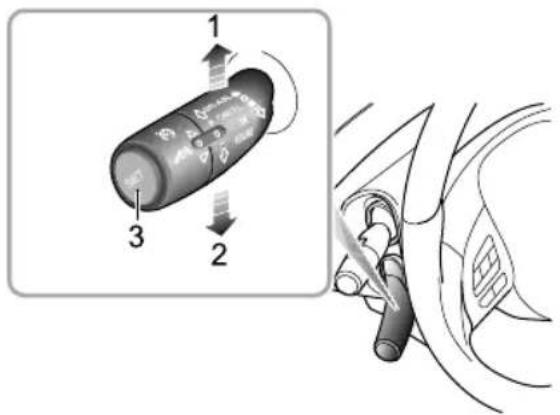
text_image
Diagram showing a car battery with labeled parts and directional arrows, alongside a close-up of its internal structure.
Whentheoverspeedalarmfunctionor
intelligentspeedlimitfunctionisenabled,thespeedlimit
STARTING&DRIVING
valueindicationilluminates.Whenthevehiclepassesthe firstspeedlimitsignidentified,thespeedlimitindication displaysthereal-timespeedlimitvalue.
Note: Whenthevehicleneedstochangelane, make aturn, orturnaroundatanintersectionandthe driverusesanindicatorinadvanceandslowsdown, theoriginalspeedlimitvalueontheinstrumentpack willberesetuntilanewspeedlimitsignisdetected. Iftheconditionsarenotmet,theoriginalspeedlimit valuewillbemaintainedandnotbereset. Thedriver MUSTobservethespeedlimitsandadjusttheirspeed accordingly.

When thenationalspeedlimitsignisidentified and the speed limit information function or intelligent speed assist function is enabled, thenationalspeed limit indication illuminates. The set of functions will work using 60 mph as thenationalspeed limit.

YISA Whentheintelligentspeedlimitfunctionis enabled,thesystemindicatorlampintheinstrumentpack
illuminatesyellow.Whenthefunctionisactivatedby pressingtheSETbuttonontheadaptivecruisecontrol lever ,thesystemindicatorlampilluminatesgreen.Ifthe intelligentspeedassistfunctiondetectsafaultorfailure, theindicatorlampwillflashyellowthenextinguish.Please trytorestartthisfunction.Ifthisfunctioncannotbe turnedon,pleasecontactanMGAuthorisedRepairer.

When the front view cameradetectsaspeed chatextmessage below, the warning lamp to remain the drivertore and act upon the themselves. The cameracannot recognisethe gesprovided below the speed limits sign, such as 100msahead, school section, 7:00-10:00. will recognise the speed limits sign with text anormalspeed limits sign driver is make correct judgement according to the text

Whenthemanualspeedlimitfunctionis systemindicatorlampintheinstrumentpack yellow.Whenthefunctionisactivatedby
STARTING&DRIVING
pressingtheSETbuttonontheadaptivecruisecontrol lever ,thesystemindicatorlampilluminatesgreen.Ifthe manualspeedassistfunctiondetectsafaultorfailure,the indicatorlampwillflashyellowthenextinguish.Pleasetry torestartthisfunction.Ifthisfunctioncannotbeturned on,pleasecontactanMGAuthorisedRepairer.
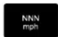
Whenthemanualspeedlimitfunctionis enabled,thespeedlimitvalueindicationilluminates.Move theadaptivecruisecontrolleverupanddowntoadjust thetargetspeedlimitvalue.The"NNN"willnowshow theadjustedspeedlimitvalue.
The drivercandirectlyswitchoff, ortemporarilysuspend the intelligentspeedlimitfunctionormanualspeedlimit functionbycarryingoutthefollowingactions:
IT otemporarilyexceedthespeedlimit(overtaking manoeuvre),presstheacceleratorpedalhard.The indicatorlampintheinstrumentpackilluminates green,andthespeedlimitvalueflashes.
2GentlypresstheSETbuttonontheendofthe adaptivecruisecontrollever, theindicatorlampinthe
instrumentpackwillchangetoyellow.PresstheSET buttonagaintoresumethefunctions.
3Movtheadaptivecruisecontrollevertothe"ON" positiontoswitchthespeedlimitfunctionoff.
Theoverspeedalarmfunctionandintelligent speedlimitfunctionmaybeimpairedinthe
followingsituations:
I Thedetectionperformanceofthefrontviewcamera isaffected.
2Thevehicleisdrivenatahighspeed.
3 Thespeedlimitsignsareobscuredalongtheroad, for example: bytrees, ice/frost, snow, dust, etc.
4 Thespeedlimitsignsareincorrectlyplacedor damaged.
5Therearemultiplespeedlimitsignsabovethelaneor onthesidesoftheroad.Currently,thefrontview cameracronlyrecognischespeedlimitsignsforthe laneinwhichthevehicleisbeingdriven.
STARTING&DRIVING
6 Nonstandardspeed limits signs or sign that contain additional information.
7 Thespeedlimitsignssetupataforkintheroad,ona bendoron-ramp/off-ramp.
8Duringmanoeuvressuchaslane-changing.
IMPORTANT
- The cameramaynotcorrectlyrecognisespeedlimit signsduringpoorlightingconditions,badweather, non-standardizedorshelteredspeedlimitsigns or the camera's own restrictions which include therecognition of similar signs (e.g., recognise a weight limits sign as speed limits sign, or recognise a minimum speed sign asthemaximspeed sign).
- Somedrasticorrapidsteeringoperationsmadeby thedrivermaybejudgedaschanginglaneorturning aroundatanintersectionbythesystem. Thiswill resultintheidentifiedspeedlimitsignsbeingcleared.
LaneAssistSystem

Thelaneassistsystemisanauxiliarysystem thatprovidesassistancetothedriver.Itdoes NOTremovetheresponsibilityofsafedriving fromthedriveWhenchoosingtousethe laneassistsystem,thedriverMUSTalways payattentiontothesurroundings,holdthe steeringwheelandbepreparedtomake manoeuvresatanytime.Failureretomaintain overallcontrolofthevehiclemayresultin anaccidentorpersonalinjury.

Theressistendoeadways recognitlaredbs. Sometimespoorroadsurfaces,certainroad structuresorobjectsmaybemistakenfor lanelinkwhensuchsituationsoccur, thelaneassistsystemmustbeimmediately turnedoff.
Thelaneassistsystemswitchislocatedintheinfotainment displendentheorrespondinginterfacedriving
assistancetoturnthesystemON/OFF, andmakemode selection.
Alert
Thesystemusesthefrontviewcameratodetectthelane linesaheadofthevehicle. Thesystemwillbeactivated whenthefollowingdetectionconditionsaremet:
•ThefunctionisswitchedON,
Vehicle speed above 37 mph (60 km/h),
- Lanelinemarkingsareclearandthesystemrecognises atleastonelaneline.
Whenawheelisabouttocrossthelaneline,orhas alreadycrossedtheline,thesystemwillprovidewarnings topromptthedrivertotakeactionandmaintainthe vehiclepositionbetweenthelanelines. Thefunctionwill automaticallyexitwhenthevehiclespeeddropsbelow 33mph (55km/h).
Emergencylanekeeping
Thesystemusesthefrontviewcameratodetectthelane linesandcurbsaheadofthevehicle. Thesystemwillbe activatedwhenthefollowingdetectionconditionsaremet:
•ThefunctionisswitchedON,
Vehicle speeds above 37 mph (60 km/h),
- Lanelinemarkingsareclearandthesystemrecognises atleastonelaneline.
Whenawheelisabouttocrossthelanelineorcurb,or hasalreadycrossedthelineorcurb,thesystemwillprovide assistancetothedriverbyattemptingtokeepthevehicle inbetweenthelanelinesbyapplyingcorrectivesteering interventionandsimultaneouslydisplayingaprompt.If the vehicle deviate front lane net much , the systemwillactivatethealerfunction.Thefunctionwill automaticallyexitwhenthevehiclespeeddropsbelow 33mph ( 55km/h ) .
Intheabsenceofasteeringinputfromthedriverforacertainperiodoftime,thesystemwillprovidewarnings.
STARTING&DRIVING
IMPORTANT
• Incases where the number of flanes increase or lanes merge, the driver MUST take full control of the vehicle.
• Inareaswheretherearecomplextrafficconditions suchasintersectionsorroadjunctionswith congestion,thedriverMUSTtakefullcontrolofthe vehicle.
Thelaneassistsystemwillbeimpairedor ineffectiveinthefollowingconditions:
•Thehazardlampsareactivated.
- Thedriverindicatesinthedirectionofthelaneline abouttobecrossed.
• Thedriverappliestheacceleratorrapidly,carriesout anemergencymanoeuvreormakesahardbrakepedal application.
- Thesystemdetectsthatthedriverhasnotmovedthe steeringwheelforapresettimeperiod(inthemodeof emergencylanekeeping).
- During system intervention the steering wheel is operated (inthemode of emergency lane keeping).
• Thelanelineistoothin, damaged, or fuzzy.
• Thecurbisirregularordamaged.
•Thevehicleisbeingdrivenonabendwithasmall curvatureradius,theroadistoonarrowortoowide.
•Thevehiclehasjustenteredaroadsectionwithlane linesorisdrivenonaroadsectionwithoutlanelines.
•Thevehiclechangeslanesorswayslaterallytoofast.
•ThevehicleisnotinD.
•Thevehiclespeedisbelow33mph (55km/h),ortoo high.
•Theanti-lockbrakesystem(ABS)andthedynamic stabilitycontrolsystem(SCS)areactivated. - Faultsexistintheanti-lockbrakesystem(ABS), dynamic stabilitycontrolsystem(SCS), electricpowersteering system(EPS), etc.
Itisrecommendedtoturnoffthelaneassist systeminthefollowingsituations:
- Drivinginasportsstyleormanner.
-
Drivinginbadweatherconditions.
-
Drivingonroughorpoorroadsurfaces.
- Drivingthroughroadworksorconstructionsites.
T rafficJamAssistSystem

Thetrafficjamassistsystemisanauxiliary systemthatprovidesassistancetothedriver. ItdoesNOTremovetheresponsibility of safedrivingfromthedriver. Whenchoosing tousethetrafficjamassistsystem, due tothelimitationsofsystemdetection and control, thedrivermustalwaysbecareful andholdthesteeringwheelatalltimes.
The driver needstocorrectortakeoverthe steering wheel control if necessary failure to maintain overall control of the vehicle may result in an accident or personal injury.
STARTING&DRIVING
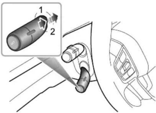
text_image
Diagram showing a car gear shift mechanism with labeled parts and directional arrows indicating motionThetrafficjamassistsystemswitchislocatedinthe infotainmentdisplay.Enterthecorrespondinginterfacefor drivingassistancetoturnthesystemON/OFF .Operating theadaptivecruisecontrollevelto"RESUME"twicewill switchthetrafficjamassistsystemintothestandbyor activestate.
Thetrafficjamassistsystemworksonthesamebasisasthe adaptivecruisecontrolsystem. Thesystemwilloperate whenthefollowingconditionsaremet:
•Theadaptivecruisecontrolsystemisactivated.
- Thetrafficjamassistsystemisswitchedonviathe correspondingbuttonintheinfotainmentsystem.
• Thesystemdetectslanelinesonbothsidesofthe vehicle.
•ThevehicleisinD.
Ifthelanelinesaheadonbothsidesareclear,thesystem canassistthevehicleindrivingwithinthelanelines.When drivingatlowspeed,ifthereisavehicleaheadandthelane linesaheadonbothsidesaren'tclear ,thesystemalsocan assistthevehicleinfollowingthetrackofthevehicleahead.
Intheabsenceofasteeringinputfromthedriverfora certainperiodoftime,thesystemwillprovidewarnings.
Note: Thedrivershouldadjustthevehiclespeedand thefollowingdistanceaccordingtotheroadvisibility, weatherandroadconditions. Thetrafficjamassist systemdoesrespontpedestriananimals, stationaryvehiclesandvehiclelesthatdriveacrossthe laneoroncomingvehiclesinthesamelank the trafficjamassistsystemcannotreducethevehicle speedtimelyandeffectively,thedriverMUSTapply thebrakecongestedconditions,shouldanother
STARTING&DRIVING
vehiclecutintothelanebeingusedbythevehicle undertrafficjamassistsystemcontrol,thesystem maynotdetectthevehicleinadequatetimetomake abrakingmanoeuvre.Inthiscasethebrakeshould beappliedbythedriver.
Thetrafficjamassistsystemwillbeimpairedor ineffectiveinthefollowingconditions:
•Thehazardlampsareactivated.
- Thedriverindicatesinthedirectionofthelaneline abouttobecrossed.
• Thedriverappliestheacceleratorrapidly,carriesout anemergencymanoeuvreormakesahardbrakepedal application.
- Thesystemdetectsthatthedriverhasnotmovedthe steeringwheelforapresettimeperiod.
- During system intervention, the steering wheel is being manipulated by the driver.
• Thelanelineistoothin, damaged, or fuzzy.
•Thevehicleisbeingdrivenonabendwithasmall curvatureradius,theroadistoonarrowortoowide.
•Thevehiclehasjustenteredaroadsectionwithlane linesorisbeingdrivenonaroadsectionwithoutlane lines.
•ThevehicleisnotinD.
•Thevehiclechangeslanesorswayslaterallytoofast.
- Theturningradiusofthecarusingthetrafficjamassist systemtotrackinfrontistoosmall.
• The anti-lockbrakesystem(ABS) and the dynamic stability control system(SCS) are activated.
- Faultsexistintheanti-lockbrakesystem(ABS),dynamic stabilitycontrolsystem(SCS),electricpowersteering system(EPS),etc.
Itisrecommendedtoturnoffthetrafficjam assistsysteminthefollowingsituations:
- Drivinginasportsstyleormanner.
- Drivinginbadweatherconditions.
- Drivingonroughorpoorroadsurfaces.
- Drivingthroughroadworksorconstructionsites.
- Drivingonsteep, windingorslipperyroads(suchas snowcoveredandicyroads, wetroadsandroads coveredwithwater).
STARTING&DRIVING
- Drivingongrasstracksorunpavedroads.
IMPORTANT
• Incaseswherethenumberoflanesincreaseor lanesmergethedriverMUSTtakefullcontrolofthe vehicle.
• Inareaswheretherearecomplextrafficconditions suchasintersectionsorroadjunctionswith congestion, thedriverMUSTtakefullcontrol.
• ThedriverMUSTbeawareofthesurroundingsand beabletoassumefullcontrolofthevehiclewhen usingthetrafficjamassistsystemtotrackthecarin frontshouldtheneedarise.
ForwardCollisionSystem

Thedriverremainsresponsibleforthesafety oftheentiredrivingprocess,evenifthe vehicleisequippedwithaforwardcollision system. ThedriverMUSTpayfullattention anddrivecarefully.Aswithallthedriver assistsystems,theforwardcollisionsystem cannotpreventaccidentsoravoidcollisions inallsituations. ThedriverMUSTalways remainincontroltoavoidaccidentsor emergencysituations.

Emergencybrakingwhilstunderthecontrol of the forward collisionsystem may cause injuriesto the passengers. Therefore, drive carefully and all passengers MUST wear seat belts at all times.

Ensure the forward collisions system or vehicle powersystem misswitched off when being towed. If the forward collisions system is enabled when the vehicle is being towed, adverse effects may affect the safety of your vehicle, the towing vehicle and the people around.

To avoid the occurrence of accidents, never specially test the function of the forward collision system.
Theforwardcollisionsystemswitchislocatedinthe infotainmentdisplay.Enterthecorrespondinginterfacefor drivingassistancetoturnthesystemON/OFF, andmake modeselection.
Alert
Whenthesystemdetectsthatthereisariskofcollision betweenthevehicleandthevehicleinfrontinthesame lane, warningswillbeprovidedtopromptthedriverto slowdownintimeandkeeparelativelysafedistancefrom thevehicleahead.
Emergencybraking
When the system detect that there is a risk of collision between the vehicle and the vehicle directly in front of the vehicle, the brakes system will automatically interveneto decelerate the vehicle, so a avoid collision accidents or mitigated damage from collision accidents. If the vehicle is braked and stopped under the system control, it will remain stationary for short time. Full control of the vehicle will then be returned to the driver.
Pedestrianautoemergencybraking
Whenthesystemdetects that there is a risk of collision between the vehicle and the mobile pedestal directly in front of the vehicle, the brakesystem will automatically intervenetodecelerat the vehicle, so a avoid collision accidents or mitigated damage from collision accidents. If the vehicle is braked and stopped under the system control, it will remain stationary for a short time. Full control of the vehicle will then be returned to the driver.
Thesystemwillonlyslowdownthevehicleautomatically ifthefollowingconditionsaremet:
STARTING&DRIVING
- Thedynamicstabilitycontrolsystem(SCS)andtraction controlsystem(TCS)arefault-freeandON.
•ThevehicleisinDorN.
•Theairbagsarenotdeployed.
Note: In some cases, the driver may no have anticipated any braking intervention and does not want to apply the brakes whilst the forward collision system is braking heavily, the driver can temporarily cancel this operation by heavily pressing the accelerator pedal after ensuring that it is safe to do so.
Theoperationoftheforwardcollisionsystem maybeimpairedorineffectiveinthefollowing situations:
The vehicle approach should cross the intersection jump the queue rapidly short distance.
• The vehicle ahead does not follow the rules of driving and parking (such as drives on the helanelines).
The vehicle ahead not in the same way your vehicle or the vehicle ahead is partially obscured.
•Thevehicleaheadisanabnormalvehicle(modifiedor abnormalshape).
•Thevehicleaheadisavehiclewithhigherchassis.
•Thevehicleaheadisalargevehicleatcloserange(such atractor, trailer, towingvehicle,mudtruck,sanitation truck,sprinklertrucketc.).
• The vehicle ahead is unusual transportation (such as horse, cart, carriages etc.).
- Thesystemdetectsthesideofavehicle.
•Thecontourofthevehicleaheadisunclear(suchas waterbeingsprayedbythewheelsofthefrontand surroundingvehicles).
•Thevehicleaheaddoesnothaveorhasobscuredtail lampswhendrivingatnightorinatunnel.
TheailampsothevehicleaheadrealLEDstriplights orotherhomemadecolouredlamps.
- Thestredightsareinconsistentorflickeringwhen drivingatnight.
- Thepedestrianisnotdirectlyinfrontofthevehicle,or thepedestrianisnotfullyvisible.
• Thepedestrianisnotstandingupright,oritisachild underacertainheight.
STARTING&DRIVING
- Thereisagroupofpedestriansinfrontofthevehicle thatisover-shadowedorinthedark.
•Thereareanimalsinfrontofthevehicle. - Objectssuchasspecial-shapedgroundobstacles(e.g. roadblocks, isolationpiles, isolationstrips, largestones, otherscatteredobjectsetc.) are detected in front of the vehicle.
- Objectssuchassigns, guardrails, bridges, buildings or other are detected in front of the vehicle.
•Thevehicleisbeingdrivenonahillsideroad,upperand lowerbridgesectionortightbend.
•ThevehicleisinR.
•Thevehicleisinastateofbrakingorrapidacceleration.
STARTING&DRIVING
LoadCarrying

DONOTexceedthegrossvehicleweight orthepermittedfrontandrearaxleloads. Failuremayresultinvehicledamageor seriousinjury.
LoadspaceLoading

Ensure that there are seat back rests are securely latched in the upright position when loads are carried in the load space behind the seats.
When luggage is carried in the load space, always ensure heavy items are placed as low and forward as possible, so to avoid the cargoshift in the event of an accidentor sudden stop.
Drivarefullydoichergenlayaking manoeuvres.
Drivingwiththetailgateopenisverydangerous. If the loadbeingcarriedrequiresthetailgatetobeopen, please ensurethecargoissuitablysecured.
IMPORTANT
Trafficregulationsmustbeobservedwhenloadingcargo, ifthecargoextrudestheloadspaceappropriatewarning measuresmustbetakentowarnotherroadusers.
InternalLoading

DONOT carryunsecureequipment, tools or luggage that could move, causing personal injuries accident; emergency braking or hard acceleration.

DONOTobstructthedriver'sorpassenger's visionwithloads.
Foldingtherearseatscanincreaseluggagespace, refer to "RearSeats" described in the "SeatsandRestraints" section.
Whencargoisloadedinthevehicle,placeitataposition aslowaspossibleandensurethatitistightlysecured,soas toavoidpersonalinjurycausedbycargomovementwhen trafficaccidentsoremergencybrakingoccurs.Ifthecargo
hastobeplacedonaseat, thentheseat must not be used by an occupant during that time.
GeneralT owingSafety
Y ourvehiclecantowatrailerifyoucarefullyobserveload limits,useapprovedequipment,andfollowthetowing guidelines.Alwayscheckloadlimitsbeforetowing.
T owingloadsinexcessofthemaximumtowingweight canseriouslyaffectvehiclehandlingandperformance,and coulddamageyourvehiclesengineanddrive-train.
Note: Exceeding any load limits advised by MGMotor is dangerous. Consult there recommended load limits and loading prior to any journey.
Checktheloadingofyourvehicleandtrailercarefully beforestartingtodrive.
T railerhitchloadshouldneverexceedthelimitadvisedby MGMotor.
Note: Excessivetowingloadsreducefronttyretraction andsteeringcontrol, toolittletrailernoseloadcan makethetrailerunstableandcauseittosway.
T owbars:OnlygenuineMGapprovedtowbarsshould befittedtoyourvehicle.Onlyusetheattachmentmethod specifiedbythevehiclemanufacturerforsecuringthe towinghitch.ContactyourauthorisedMGdealerfor moreinformation.
Safetyhairsafetyhaimusbeseed
precautionarymeasureshouldthetrailerbecome unintentionallyunhitche Makesurethesafetychainis securelyattachedtobothetrailerandthevehicleprior todeparture.
Altitude: ourenginedeliverslesspowerathigher altitudlyoutowatrailerinamountainousareayou shouldreducethecombinedvehicleandtrailerweightby 10%forevery1000mofelevation.
Gradients: Wherepossible, whentowing, you should plan your journey to avoid steep gradient. The advised braketowing mass stated assumes a maximum gradient capability of 12% here possible it is recommended you drive on gradients less than 12% follow the trailer associations recommendations for suitable roads.
STARTING&DRIVING
Runninginperiod: Avoidtowingatrailerduringyour vehiclesfirst625miles1000km.
Stop/Startfunction: Onvehiclesfittedwitha
Stop/Startfunction, manually switch the Automated Stop/Startfunction OFF when towing. The trailer weight can affect your vehicle's braking efficiency if Automated Stop/Start is activated on a hill while towing at a trailer.
EmergencyInformation
246HazardWarningDevices
247eCall-SOSEmergencyAssistance
250 EmergencyStarting
252VehicleRecovery
256TyreRepair
264 FuseReplacement
271 BulbReplacement
EMERGENCYINFORMATION
HazardWarningDevices
WarningTriangle
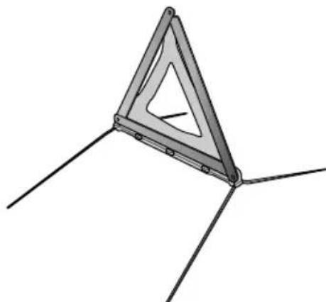
natural_image
Pure geometric diagram of a triangular structure with three legs and internal lines, no text or symbols present.The warning triangles supplied with your carisstowed in the load space.
If you havetostopyourcarontheroadinanemergency, you must place awarning triangle approximately 50-150
metresbehindthecar,ifpossible,andpressthehazard warningswitchtowarnotherroadusersofyourposition.
EMERGENCYINFORMATION
eCall-SOSEmergencyAssistance
Inanaccident, your vehicle's call–SOSEmergency Assistance can either be triggered manually or in severe cases automatically up on detection by vehicle's sensors.
TheeCallserviceisapublicserviceofgeneralinterestand isaccessiblefreeofcharge.Theemergencycallcentrewill establishverbalcommunicationwiththevehicleoccupants inordertounderstandtheextentoftheemergency and thelevelofassistancerequired.Ifverbalcommunication isnotachievableanattemptwillbemadetosendthe followingvehicleinformationmessagetotheemergency callcentre.Theappropriateemergencyserviceswillbe deployedtothevehicle'scurrentlocationifknown.
•Currenttime,locationanddirectionoftravel
•Vehicletype
•Vehicleidentificationnumber(VIN)
- Whetherthecallwasautomaticallyormanuallyinitiated
•Vehiclecategory
This system will ensure that your personal data is securely protected. It is designed to ensure that it is not traceable and other external systems are not able to gain access.
WhentheeCalltriggers, thesystemwillonlytransmitthe datainformationtotherelevantpublicsafetyanswering pointsdesignatedbytherespectivepublicauthoritiesof thecountryonwhichterritorytheyarelocated, which willreceiveandprocessyouemergencycallrequest. The systemwillretaindatalocallywithin13hoursoftriggering.
You havetherighttoaccessthedatainformationstored in this system, and to request therectification, erasure or blocking of data information that does not meet the requirements of the regulations when you think your personal data is infringed, you havetherightt o complain to the competent dataprotection authority.
Formanualactivation, pressandreleasetheSOSbutton intheoverheadconsoleforabout l secondtoactivate an emergency servicescall. Asinglebeepwillbeheard when theeCallistriggeredandamessagewillbedisplayed on thevehicle'smessagecentreandentertainmentplayer. The entertainmentplayerwillbemutedwhilsttheemergency servicescallisactManuallytriggeredemergency servicescallsmaybecancelledbypressingandreleasing theSOSbuttonagainwithinabout5secondsoftheinitial press,andthemessageswillberemoved.
EMERGENCYINFORMATION
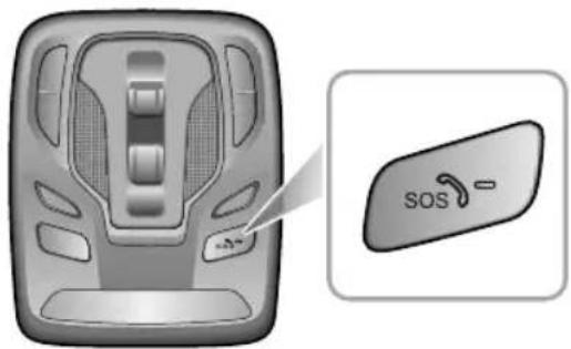
text_image
SOSTheemergencyservicescall(eCall)systemwillperforma self-testwhenthevehiclepowersystem/ignitionisturned ON.DuringaSelf-T esttheemergencyservicescall(eCall)LEDstatusindicatorontheSOSbuttonwillflashquickly untilcompletion.TheLEDstatusindicatorwillilluminate permanentlyifnosystemfaultsarepresent.TheLED statusindicatorwillbeextinguishedorflashslowlyifa
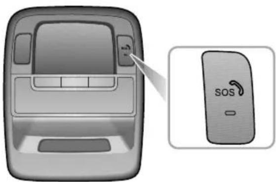
natural_image
Illustration of a car interior with a touchscreen and a close-up of the SOS switch (no text or symbols on the device itself)faultisdetected.Faultsdetectedduringtheself-testwill bedisplayedonthevehiclesmessagecentre.
Note: The operation of Call-SOSEmergency Assistancer relies on cellular coverage and maybe affected by signal outages or low signal strength.
EMERGENCYINFORMATION
Note: The automatic emergency services call (eCall) function may be disabled by local MGA authorised Repairer upon request.
Note: It is strongly recommended the call function is not disabled, any action requested by the owner must be accompanied by a signed request.
EMERGENCYINFORMATION
EmergencyStarting

NEVERattempttopowerthevehicleby pushingortowing.

Makesurethatbothbatteriesareofthesame ratedvoltage(12volts),andthatthebooster cablesareapprovedforusewith 12voltcar batteries.

Ensuresparksandnakedflamesarekeptwell awayfromthefrontcompartment.

Ensure that each boostercable connection is securely made. Theremust benorisk of touching each other or other moving parts, this could cause sparking, which could lead to fireorexplosion.
Whenthebatterylosespower,theboostercablescanbe usedtoconnectthebatteryofadonorvehicleorexternal batterytostartthevehicle.
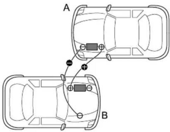
text_image
A BEnsuretheSTART/STOPSwitchisturnedoffandswitch offALLelectricalequipmentofBOTHvehicles,thenfollow theinstructionsbelow:
I ConnecttheREDboostercablebetweenthepositive (+)terminalsofbothbatteries. ConnecttheBLACK boostercablefromthenegative(-)terminalofthe donorbattery(A)toagoodearthpoint(CCUhousing orotherunpaintedsurface,forexample),asfaraway
EMERGENCYINFORMATION
from the battery as possible and well away from brake lines on the disabled vehicle (B).
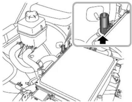
natural_image
Technical diagram of a vehicle engine compartment with an inset showing a cylindrical component inserted into the engine (no text or labels present)2Poweruporstartthedonorvehicleandallowitto runforafewminutes.
3Poweruporstartthedisabledvehicle.Ifthedisabled vehicledoesnotpoweruporstartafterseveral attempts,itmayneedtoberepaired.Pleasecontact anMGAuthorisedRepairer.
4Afterboththevehicleshavenormally started/powered,turnofftheSTART/STOPSwitchof thedonorvehicle.
5Disconnectingtheboostercablesmustbeanexact reversaloftheprocedureusedtoconnectthem,i.e. disconnecttheBLACKcablefromtheearthpointon thedisabledvehicleFIRST.
IMPORTANT
DONOTswitchonanyelectricalapplianceinthe disabledvehicleuntiltheboostercableshavebeen disconnected.
Note:Itisrecommendedtoturnofflighting,air conditioningandothercomfortappliances and ensurethatthedisabledvehicleremainspoweredor runfomorethan\~boursefterstartedn ordetrecovethbatterpowdvehicle stillfaikostart/powernormallyafterfullcharging, pleasecontactanMGAuthorisedRepairer.
EMERGENCYINFORMATION
VehicleRecovery
T owingforRecovery
T owingHook

Whenpushingortowingthevehiclefromadangeroussituationorontothetransporter,thespeedmust remainbelow3mphandbecompletedwithin3minutes.

Whenpushingortowingthevehicleontothetransporter, thedriver'ssideseatbeltshouldbeinserted intothelockandmaintainedintheinsertedstateinordertoreleasetheEPB.

DONOTuseatowropethatistwisted-orthetowinghookmaybeunscrewed.

DONOTtowthevehiclewithanyofthedrivenwheelsincontactwiththeroadsurface,thiswillavoid electricdrivetransmissiondamage.
EMERGENCYINFORMATION
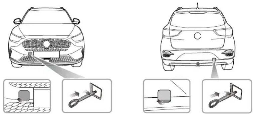
Y ourcarisequippedwith2towingeyes(locatedatthefrontandtherearofthevehicle),whichareusedforfittingthe towinghook. Thetowinghookisplacedbeneaththeloadspacefloor .T ofitthetowinghook,removethesmallcoverset intothebumper,firstpressoneendofthesmallcoverplate,thenopenthesmallcoverplateaftertheotherendislifted, thenscrewinthetowinghookviathesmallholeintothethreadedholeinthebumperbeam(seeillustration).Ensurethe towinghookisfullytightened!
Note: Thetowingeyecovermaybesecuredtothebumperbyaplasticcord.
EMERGENCYINFORMATION
Bothtowingpointsareintendedforusebyqualifiedrecoveryspecialiststoassistintherecoveryofyourcarwhena breakdownoraccidentoccur. Theyarenotdesignedfortowingothervehicles, andmustNEVERbeusedtotowatrailer orcaravan. Thevehiclecanbetowedusingatowropebutatowingbarisrecommended.
T owingforRecovery

Whentowing, DONOTsuddenlyaccelerate orbrakesuddenly, this can cause accidents.
SuspendedTowing
Suspendedtowingisthebestmethodforrecoveringa vehiclethatneedstobetowed. ThedrivewheelsMUSTbe suspendedabovetheground.EnsuretheEPBisreleased whentherearwheelsareincontactwiththeroadsurface. SwitchthehazardlampsONandensurenopassengersare inthevehicle.
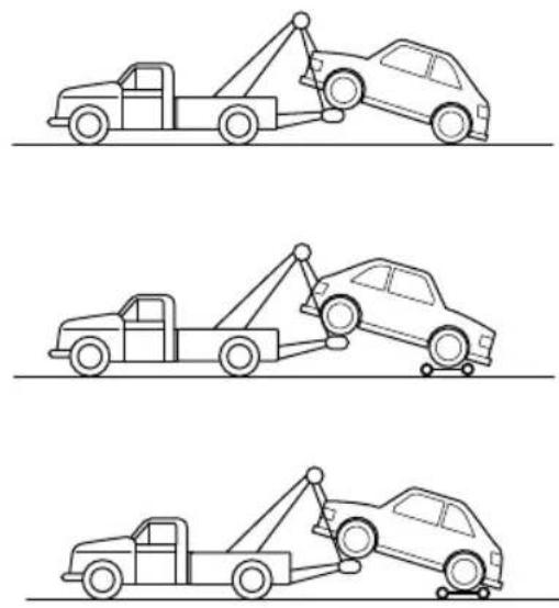
EMERGENCYINFORMATION
T ransporterorT railer
If your caristobetransported on the back of a trailer or transporter, it must be secured as illustrated:
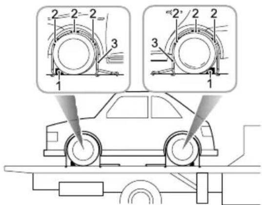
text_image
Diagram illustrating car wheel assembly with labeled components and directional arrows indicating motion or force analysis.I Apply the parking brake and placethelectric drive transmission in park.
2Fitwheelchocks(1)asshown,thenpositiontheanti sliprubberblocks(2)aroundthecircumferenceofthe tyre.
3Fitthelashingstraps(3)aroundthewheelsandsecure tothetrailer.Tightenthestrapsuntilthecaris securelyheld.
EMERGENCYINFORMATION
T yreRepair
Y ourvehicleisequippedwithlowwindresistancewheel trimcovers,whicharefixedbysnaps.Ifyouneedto removeorinstallthewheeltrimcover ,pleasepayattention tothefollowingprecautions:
- Whenremovingthetrimcover,it'sbettertopullthe trimcoverapartatseveralpositionssimilarto1 (see illustration).PleaseDONOTpullthetrimcoverat otherpositionstoavoiddamagingit;
- Whenremovingthetrimcover,pullthefivebestpulling pointsonebyone,andremovethewheeltrimcoveras awhileafterallofthemarepulledapart;
- Wheninstallingthetrimcover,pleasecheckthevalve markonthebackofthetrimcover(asshowninthe enlargedillustration),alignthenearesthollowofthe trimcovernexttoitwiththevalveonthewheel,and theninstallittoensurethatthevalvecanbeexposed fromthehollow.Andthenclampthetrimcoverin place.
Note: Whenthenewvehicleleavesthefactory, the dustcapofthevalvemaybealittletighis recommended that youremovethewheeltrimcover
firstduringthefirstinflationoperationndthen screwoffthedustcapwhenthereisenoughspace.
Note: If the pulling for certain to remove the wheel trim cover is large, use suitable tool to pull out.
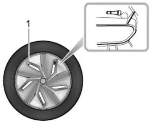
natural_image
Diagram of a car wheel with blades and a close-up inset showing the blade assembly (no text or symbols)EMERGENCYINFORMATION
T oolldentification
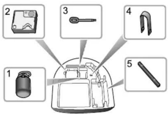
text_image
Diagram showing exploded view of a device with labeled parts including battery, switch, and cable componentsI RepairFluid
2ElectricAirPump
3T owingHook
4WheelBoltCapRemovalTool
5WarningTriangle
T yreRepair
I Removethelabelatthebottomoftherepairfluid reservoirandattachittothesteeringwheeltoremind thedrivernottoexceed50mph.
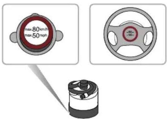
text_image
max 80 km/h max 50 mph2Connecttheairhoseoftheelectricairpumpto therepairfluidreservoir,fitthetyresealantbottle (upright)intotheslotonthecompressor .Remove thevalvedustcapoftheflattyre,andconnectthe fillerhosefromthetyresealantbottletothetyre
EMERGENCYINFORMATION
valve.Ensurethatthepowerswitchoftheelectric aircompressorisswitchedoff(i.e.,press“O”),then inserttheplugfromthecompressorintothecentre consolepowersocket,andturnthevehiclepower systemtoON/READY.
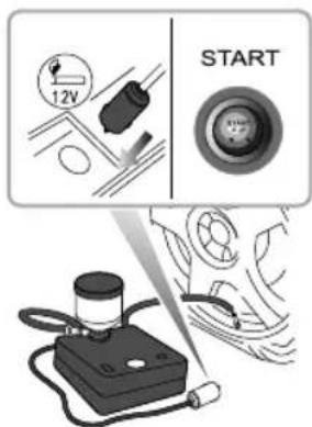
text_image
12V STARTNote: To avoid battery discharge, it is recommended to keep the vehicle and READY mode.
Switch the powers switch of the electric compressor (i.e press-") to pumping alari at the tyre. Thetyresealant bottle will become empty after approximately 30 seconds. Thetyreshould reach the specified pressure within 5 or 10 minutes.
Not the pressurgaug map briefly each bar(87psi), thenthe pressure beginstodropto normal.
When therequire pressures each switch of the powerswitch of the electric compressor (i.e., press "O").
Ntifrequirepressurcannbereachedwithih0minutepleasdisconnect thecompressor,drivethevehicle10metres(33feet)approxforwardorbackwardtoallowthe sealanttospreadwithinthetyrdftherequired pressureastilldreachedtheyis severelydamagedandyoushouldseekassistance fromtheRoadsideAssistancecompanyoranMG AuthorisedRepairer.
EMERGENCYINFORMATION
Note: Continual operation of the electric air compressor for more than 10 minutes may result in damaggetothecompressor.
Note: Undernocircumstances should you continue your journey with a deflated tyre. Driving vehicle with a deflated tyre is extremely dangerous.
5Removethetyresealantbottlefromtheslotinthe compressor, disconnect the hose fromthetyre valve, removethe compressor plug from the centre console powersocket, returnthetyrerepair kitto its stowage tray.
After successfully adding sealant they drive immediately for short time (around n minute). This will allow these sealant to distribute evenly inside the tyre. Continued driving and donot exceed 50 mph. After further 10 minutes, find as safe placetostop and recheck the tyre repressure.
Please follow different guidelines based they re pressure measured:
If the teryrepressure has dropped to less than 0.8 bar (11.6 psi), donot continued driving, seek assistance instead.
If the tyrepressure is between 0.8 bar (11.6 psi) and specified pressure, use the electric air pump to flat the tyrentile reaches specified pressure. Repeat the operations of step 6.
theypressurhasdropped, may continu driving but vehicle speed has not exceed 50 mph, and the driving mileagem must not exceed 125 miles.
Note Pleaseregularlycheckthetyresealant 'useby date' and replace as necessary.
NDIO Emofereigjedsg. screws, nailsfromtheyrTheyreepaisystem musonlpressedwhenforeignbjectinthe treaφatter(A)DONO Tttemptrepaiwhen thedamageisinthesidewallofthetyre(B).
EMERGENCYINFORMATION
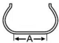
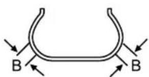
text_image
B BChangingaWheel \*
Ifyouneedtochangethewheelduringthejourney,choose asafeplacetostopawayfromthemainroadifpossible. Alwaysaskyourpassengerstogetoutofthecarandwait inasafeareaawayfromothertraffic.
Switchonhazardwarninglamps. If available, position awarning triangle about 50 to 150 metres behind your vehicle to warn approaching traffic.
Beforechangingawheel,ensurethefrontwheelsarein thestraightaheadposition.Applytheparkingbrakeand, wherepossibleensurePisselected.
Observethefollowingprecautions:
- Ensurethejackispositionedonfirm,levelground.
• If the vehicle must be parked on the hill, placechocks in front of and behind the other 3 wheel stop prevent the vehicle moving.
EMERGENCYINFORMATION
PositioningtheJack

NEVERworkbeneaththecarwiththejack astheonlymeansofsupport. Thejackis designedforwheelchangingonly!

NEVERjackthecarusinganyjackingpoints otherthantherecommendedjackingpoints. Seriousdamagetothecarcouldresult.
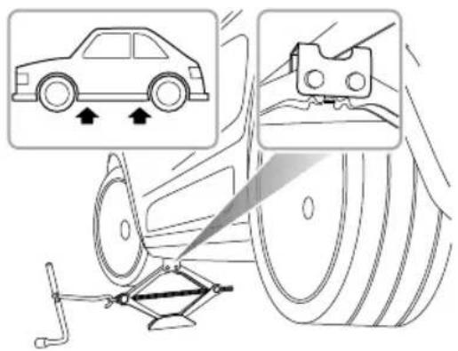
text_image
Diagram illustrating car tire mounting technique with magnified views showing vehicle and clamp placement
Avoidaccidentalcontactwithanyunderbody parts,thehighvoltagebatterycasing.
Positionthejackonfirmlevelgroundunderthejacking pointnearestthewheeltoberemoved. Notethatthe domedheadofthejackmustfitintothecorresponding recessinthesillplate(Thereisatriangleindicatorinthe areashownbythearrowhead.).
T urningthejackscrewbyhand,adjustthejackuntilthejack headfitssnuglyontothesillinthecorrectarea.Ensurethat thebaseofthejackisinfullcontactwiththelevelground.
FittingtheSpareWheel

Regularlycheckthesparewheeltyre pressurinndesefdong periodsoftime.Afterfitmenttthefirst opportunithedadjusttyre pressure.

The wheel turns heightened the specified torque after changing a wheel (120 \~ 130Nm).
EMERGENCYINFORMATION
I Before raising the car, removethewheel trim cover.
Usethewheel bolt spannertoslackeneachbol thalfa
turnanti-clockwise.
2T urnthehandleinaclockwisedirectionuntilthetyre isclearoftheground.
3Removethewheelboltsandplacetheminthetooltray topreventthemfrombeinglost.Makesurethevehicle issteadyandthereisnoriskofslipormovement beforeremovingwheelbolts.
4Removetheroadwheel.
Note: Avoidplacingwheelsfacedownonthe ground-thesurfacemaybescratched.
5Fitthesparewheelandtightenthewheelboltswith wheelboltspanneruntilthewheelisseatedfirmly againstthehub.
6Lowerthecarandremovethejack, thenFULLYtighten thewheelboltsinadiagonalsequence.
7Finally, return the tool to the toolbox, put the toolbox into the well of the boot floor, tight the spare wheel retaining nuts, and put there placed wheel above the
toolboxinthewellintheloadspacefloor(facedown).
Lowerthebootfloor, and put the boot storage box on the boot floor.
Note: DONOT standon the handle of the wheel bolt spanner or use extension tube on the handle of the spanner.
Note: When replacing the wheel, please fully tighten the bolts in the diagonal sequence twice.
Note: ConsultyourMGAuthorisedRepairer.ortyre specialistforareplacementtyre, as soon as possible.
SpacesaverSpareWheel

Onlyonespacesaversparewheelcanbeused atanyonetime,otherwisetheoperational performanceandbrakeperformancemaybe reduced,therebyleadingtoaccidentorinjury toyourselfandothers.
EMERGENCYINFORMATION

Whendrivingonicyorslipperysurfacesitis advisedtofitthespacesaverwheeltotherear ofthevehicletomaintinadaquatestability. Thismaymeanswappingafrontwheelwith arearwheel.

Snowchains cannot be used on the spacesaversparewheel, this can cause damage to the car and snow chain.
Whenthespacesaversparewheelisfitted,thevehicle speedshouldnotexceed50mph.Pleasehavethefull-scale tyrerepairedandreplacethesparewheelassoonas possible.Thiswillextendthelifespanofthesparewheel forotheremergencies.
Note: DONOTuseanautomaticcarwashwhen thespacesaverwheelisfitted, theguiderailsofthe cawashmayconflictwiththewheel/tyrendause damage.
EMERGENCYINFORMATION
FuseReplacement
Fuse
Fusesaresimplecircuitbreakerswhichprotectthevehicle electricalequipmentbypreventingtheelectricalcircuits frombeingoverloaded.Ablownfuseresultsintheitem ofelectricalequipmentitprotectsfailingtowork.
Checkasuspectfusebyremovingitfromthefuseboxand lookingforabreakinthewireinsidethefuse.
It is recommended to have spare refuses in the vehicle, these can be obtained from a local MGA authorised repairer.
IMPORTANT
- NEVERattempttorepairablownfuse.ALWAYS replaceafusewithoneofthesamerating.
- Ifareplacedfusefailsimmediately,pleasecontactan MGAuthorisedRepairerassoonaspossible.
FuseBox
Therearetwofuseboxesinthevehicle :
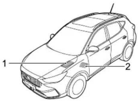
text_image
1 2IFrontCompartmentFuseBox (attheleftsideofthe FrontBay).
2PassengerCompartmentFuseBox (belowtheglove boxatthefrontpassengerside).
EMERGENCYINFORMATION
PassengerCompartmentFuseBox
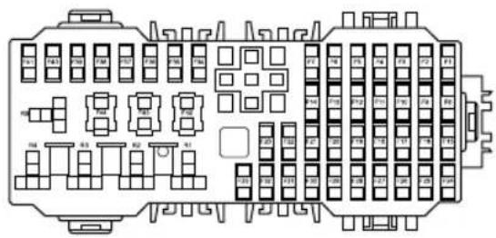
text_image
Technical diagram of an internal combustion engine fuse box with labeled components and mounting pointsCheckorReplaceaFuse
I Switchoffthevehiclepowersystemandallelectrical equipment, disconnectthebatterynegativecable.
2Removetheclosingpanelbelowthegloveboxtogain accesstothefusebox.
3Pressthefuseextractiontoolontothefusehead andpulltoremovethefuse.Ablownfusecanbe recognisedbyabreakinthewire.
4Replacetheblownfusewithasamerating.
FuseSpecification
| Specs | Function | |
| F1 | 5A | ChargingPlugLockRelay, ChargingPlugUnlockRelay |
| DiagnosticLineConnector | ||
| SA F3 | CombinedChargingUnit, ElectricVehicleCommunication ControllerBatteryPressure AlarmSwitch | |
| 15A F4 | FrontWasherRelay,Rear WasherRelay | |
| F5 | Se5AingDiagnosticModule | |
| AV ofagePTC,ESSPTC | ||
EMERGENCYINFORMATION
| NO.Spec | Function | |
| F7 | 10AEnergyStorageSystem | |
| 5A F8 | EPBSwitch,TyrePressureMonitoringSystem | |
| F95AVehicleControlUnit | ||
| F1010APedestrianAlertControlModule | ||
| F11 | 5A | PassiveEntryPassiveStartModule |
| F125A | PowerElectronicBox | |
| F1330ADriverSeatAdjustSwitch | ||
| F145ABackupImmobilizerCoil | ||
| F15 | 15AFrontPowerSocket | |
| F165A | OutsideMirrorandMasterLightHeightAdjustSwitch,T opUSB,LeftHeadlampAssembly,RightHeadlampAssembly | |
| NO.Specs | Function | |
| F17 | 5APhoneWirelessCharger | |
| F185ARearUSB | ||
| F195AE-CallTBOX | ||
| F205ATBOX | ||
| F2110A | AroundViewModule,Radio BroadcastingReceptionModule, FrontCentralDisplay | |
| F2210A | ExteriorMirrorsHeatingElement | |
| F2325A | RearWindscreenHeating Element | |
| F2420A | FrontInfotainmentControl Module | |
| F2515A | AutomaticTemperature Controller | |
| F265A | InstrumentPack | |
EMERGENCYINFORMATION
| NO.Specs | Function |
| F2710A | InformationFaceplate,Outside MirrorandMasterLightHeight AdjustSwitch,DriverDoor SwitchPack |
| F285A | RearDrivingAssistanceSystem, RainLightSensor |
| F2910AGateway | |
| F3010AGateway | |
| F3130ASunroofMotor | |
| F3230ASunshadeMotor | |
| F335ASHiftControlUnit | |
| F3410AElectronicSteeringColumnLock | |
| F3515ASuperLockRelay | |
| F365ACHargingFlapMotor | |
| F37-4I-- |
| NO.Specs | Function | |
| F4240A | Stability | ControlModule(Valve) |
| F4330A | DriverWindowLifter,RearRight WindowLiftSwitch | |
| F4430A | PassengerWindowliftSwitch, RearLeftWindowLiftSwitch | |
EMERGENCYINFORMATION
FrontCompartmentFuseBox
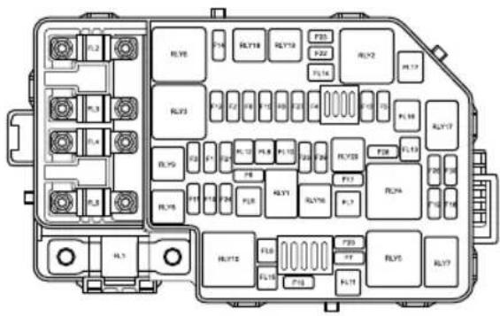
text_image
Diagram of an internal combustion engine fuse box with labeled components and terminal numbersCheckorReplaceaFuse
Switch of the vehicle power system and electrical equipment disconnect battery negative cable.
Preshlocating lipstremovehusboxid.
Preschusextractionpointthushead and putloemovthuslowfuscabe recognized by prealithewire.
Replacehousewithamcrating.
FuseSpecification
| SpkQs | Function | |
| FLI | 200 Ambined Charging Unit | |
| 80FLi3PoweSteeringModule | ||
| 40FLi3FarRelayPack | ||
| 80FL4 | PassengerCompartmentFuseF1-F7F19-F2IF34F35F42F44 | |
EMERGENCYINFORMATION
| NO.Specs | Function | |
| FL5 | 80A | Windscreen/MirrorHeatingRelay, PassengerCompartmentFuse F8-F14,F24-F33,F43 |
| FL6 | - | - |
| FL7 | 40A | AutomaticT emperature Controller ,Blower |
| FL820 | ABodyControlModule | |
| FL940 | AStabilityControlModule(Pump) | |
| FL1030 | ABodyControlModule | |
| FL11 | - | - |
| FL1220 | ABodyControlModule | |
| FL13 | - | - |
| FL14 | - | - |
| FL15 | 30A | KLRRelay |
| NO.Specs | Function | |
| FL1630A | ElectricParkingMotorControl Unit | |
| FL17 | 40A | EVPRelay |
| F1 | - | - |
| F215A | PEBCoolantPump,CoolingFan RelayPack | |
| F3 | - | - |
| F4 | - | - |
| F5 | 10A | ElectricAirConditioning Compressor |
| F6 | - | - |
| F7 | 30A | FrontWiperEnableRelay,Front WiperHigh/LowSpeedRelay |
| F8 | - | - |
| F9 | - | - |
EMERGENCYINFORMATION
| NO.Specs | Function | |
| F1010A | RightHeadlampAssembly | |
| F11 | 10ALeftHeadlampAssembly | |
| F12 | - | - |
| F1315A | HornRelay | |
| F14 | - | - |
| F15 | 5ABrakePedalSwitch | |
| F1615A | RearWiperRelay | |
| F17 | - | - |
| F185A | SensingDiagnosticModule | |
| F195A | VehicleControlUnit | |
| F20 | - | - |
| F2115A | BodyControlModule | |
| F2210A | FrontLeftSeatHeatingRelay | |
| F2310A | FrontRightSeatHeatingRelay | |
| NO.Specs | Function | |
| F24 | - | - |
| F2515A | BodyControlModule | |
| F26 | - | - |
| F275A | BodyControlModule,EVPRelay, FrontBreathingLamp | |
| F2815A | AESSCoolantPumpRelay | |
| F29 | - | - |
| F3010A | ShiftControlUnit,BodyControl Module,InstrumentPack,PDC Sensor,FrontViewControl Module,FrontDetectionRadar, E-CallTBOX,AirbagDisplay Module | |
BulbReplacement
BulbSpecification
| LampBulb | Specifications |
| HeadlampHigh/Low Beam | LED |
| FrontDirection Indicators | LED |
| DaytimeRunningLampsLED | |
| FrontSideLight | LED |
| ReverseLamps | W16W16W |
| RearDirectionIndicators | WY16W16W |
| RearSideLight | LED |
| LampBulb | Specifications |
| StopLamps | LED |
| LicensePlateLampsW5W5W | W |
| RearFogLampsLED | |
| HighMountedStopLamp | LED |
| InteriorLamp(bulb configuration) | W5W5W |
| InteriorLamp(LED configuration) | LED |
| LoadSpaceLampC10W10W |
EMERGENCYINFORMATION
BulbReplacement
Beforereplacinganybulb,turnofftheSTART/STOPSwitch andlightingswitchtoavoidanypossibilityofashortcircuit.
Note: MGonly recommends replacement bulbsthat completely meet them manufacturers specifications.
Take care NOT to touch the glass with your fingers; always use a cloth to handle the bulb. If necessary, clean the glass with methylated spirit to remove fingerprints.
Ifindoubt,whenreplacingbulbs,contactanMG AuthorisedRepairer.
Forreplacementofotherbulbsnotlistedpleaseconsultan MGAuthorisedRepairer.
ReverseLampsBulbRenewal
I Openthetailgate.
2Disconnectthebatterynegativeterminal.
3Usingasuitableprybarorlever,carefullyremovethe covertrim.
4Usingasuitablespanner/socketwrench,removethe3 screws(1)securingthelamptothetailgate.Remove the wiringconnector(2).Releasethelampassembly andremoveawayfromthebody.
EMERGENCYINFORMATION
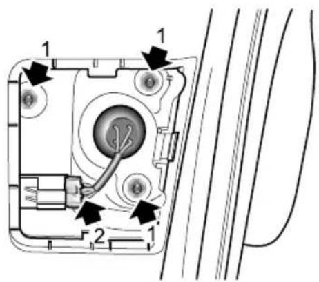
text_image
Technical diagram of a device interior with numbered components and directional arrows indicating flow or movement.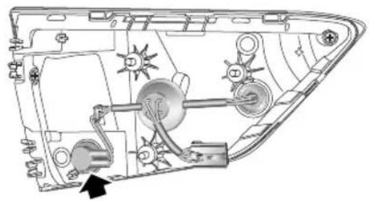
natural_image
Technical diagram of a vehicle's internal components, showing hoses, wheels, and wiring (no text or labels)5Rotatethebulbholderinananti-clockwisedirection.6Removebulbholderandremovebulb.
7Fitnewbulbtobulbholder.
8Insertbulbholderinlampassembly, rotateclockwise untilfullysecure.
9Ensurelampsealiscorrectlylocated.
10Positionlamptotailgate, refitthewiringconnector andthescrewfixings, andtightento2.7-3.3Nm.
EMERGENCYINFORMATION
I I Refitscrewcovertrim.
12Reconnectbatterynegativeterminal.
13T estlampoperation.
14Closetailgate.
LicensePlateLampsBulbRenewal
I Disconnect the battery negative terminal.
2Forlicenseplatelampsbulbreplacement,itis necessarytoremovetherearbumpercover ,seek guidancefromanAuthorisedMGRepairer.
3Removethewiringconnector.
4Rotatethebulbholderinananti-clockwisedirection.
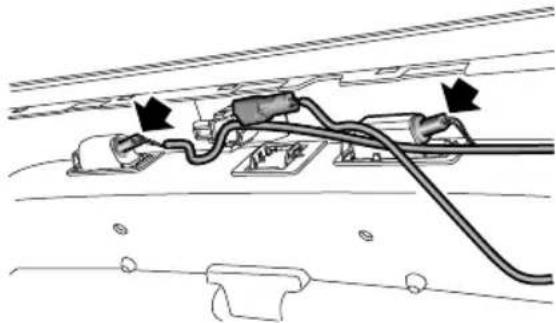
natural_image
Diagram of a mechanical or electrical component with wires and connectors, no visible text or symbolsEMERGENCYINFORMATION
5Removebulbholderandremovebulb.
6Fitnewbulbtobulbholder.
7Insertbulbholderinlampassembly, rotateclockwise untilfullysecure.
8Refitthewiringconnector.
9Fittherearbumpercover.
10Reconnectbatterynegativeterminal.
IIT estlampoperation.
RearDirectionIndicatorBulbRenewal
1 Openthetailgate.
2Disconnectthebatterynegativeterminal.
3Usingasuitableprybarorlever,carefullyreleaseand removethesecuringscrewcovertrim.
4Usingasuitablespanner/socketwrench,removethe2 screwssecuringthelamptothebody.
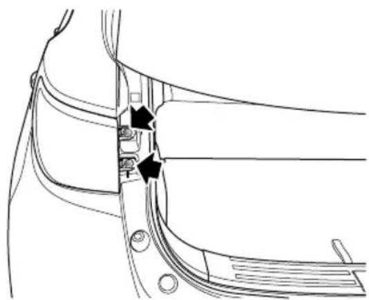
natural_image
Technical line drawing of a mechanical component with no visible text or symbolsEMERGENCYINFORMATION
5Removethewiringconnector.Releasethelamp assemblyandremoveawayfromthebody.
6Rotatethebulbholderinananti-clockwisedirection.
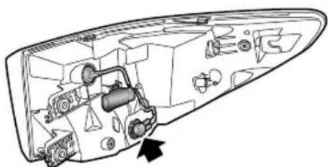
natural_image
Technical line drawing of a mechanical component with internal parts and an arrow indicating direction (no text or symbols)7Removebulbholderandremovebulb.
8Fitnewbulbtobulbholder.
9Insertbulbholderinlampassembly, rotateclockwise untilfullysecure.
10 Ensure lampseal is correctly located.
11Positionlamptobody, refitthewiringconnector, start bothscrewfixings, and tightento3-5Nm.
12Refitscrewcovertrim.
I3Reconnectbatterynegativeterminal.
14T estlampoperation.
15Closetailgate.
EMERGENCYINFORMATION
InteriorLampBulbRenewal
I Disconnect the batterynegativeterminal.
2Lightlyprizeoffthelamplensfromthelampassembly usingaflat-bladescrewdriver.
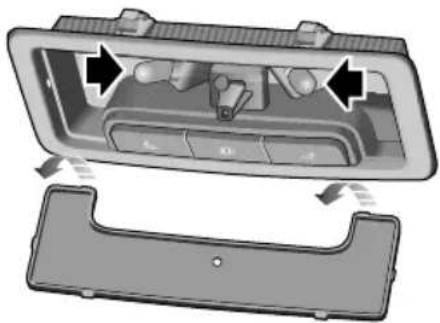
natural_image
Interior view of a car dashboard with control panel and rear door (no text or symbols visible)3Pullthebulbfromitsmountingtoremove.
4Installnewbulb.
5Installthelens,locatethetwoprongsatthefront ofthelensandthencarefullyflexthelenstolocate thetwoprongsattherearofthelensintothelamp
assembly.Pushthelensupwardsuntil‘clicks’into position
6Connectbatterynegativeterminal.
7T estlampoperation.
EMERGENCYINFORMATION
LoadSpaceLampBulbRenewal
1 Openthetailgate.
2Disconnectthebatterynegativeterminal.
3Insertasuitabletoolorsmallflatbladedscrewdriver intotheindentononeofthenarrowsidesofthelens andcarefullyremovetheunitfromitslocation.
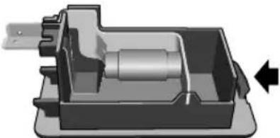
natural_image
3D mechanical component diagram showing internal shaft and housing (no text or symbols)4Pushagainstspringpressureandliftthebulbtoremove it.
5Installnewbulb.
6Refittheunit, pushuntilfullysecured.
7Connectbatterynegativeterminal.
8T estlampoperation.
9Closetailgate.
Maintenance
280Maintenance
283Bonnet
285 FrontCompartment
286CoolingSystem
288Brake
290 Battery
292HighVoltageBatteryPack
294Washer
296Wipers
299 Tyre
305CleaningandVehicleCare
MAINTENANCE
Maintenance
RoutineServicing
Thesafety, reliability and performance of your car will depend partly on how well it is maintained. You must ensure that maintenance is carried out when required and according to the information contained in the "Service Schedule"-seewww.mg.co.uk-ownerssection.
Servicing
Fornextserviceinformationpleaseconsultyourservice records.
SomemarketsfeatureaservicereminderinthelPK messagecentre.
ServiceHistory
EnsureMGAuthorisedRepairerregisterstheService Historyaftereachservice.
BrakeFluidReplacement
Replacethebrakefluidaccordingtotheinformation containedinthe"ServiceSchedule"-seewww.mg.co.uk-ownerssection.
Note: Brakefluidreplacementwillbeanadditional cost.
CoolantReplacement
Thecoolant(anti-freezeandwatersolution)needstobe replacedaccordingtotheinformationcontainedinthe "ServiceSchedule"-seewww.mg.co.uk-ownerssection.
Note: Coolantreplacementwillbeanadditionalcost.
OwnerMaintenance

Anysignificantorsuddendropinfluidlevels, oruneventyrewear,shouldbereported withoutdelaytoMGAuthorisedRepairer.
In addition to other routines services referred to previously, an number of simple checks must be carried out more frequently. Advice is given on the page that follows.
DailyCheck
•Operationoflights,horn,wipers,washersandwarning lamps.
•Operationofseatbeltsandbrakes.
- Lookforfluiddepositsunderneaththecarthatmight indicatealeak.
- Checktyreappearance.
WeeklyCheck
- Coolantlevels.
- Brakefluidlevel.
•Windscreenwasherfluidlevel.
- Operateairconditioning.
SpecialOperatingConditions
If your car is frequently used industry conditions, or operated in extreme climates where sub-zero or very high ambient temperatures are normal, more frequent attention may need to be paid to servicing requirements. You need to carry out special maintenance operations (refertoService Schedule) or contact an MGA authorised Repairer.
SafetyintheGarage

Coolingfansmaycommenceoperatingafter thevehicleisswitchedoff,andcontinue operatingforanumberofminutes.Keep clearofallfanwhileworkingthefront motorcompartment
If you need to carry out maintenance, observ the following safety precautions at all times:
- Ifthecarhasbeendrivenrecently,DONOTTOUCH coolingsystemcomponentsuntilthedrivemotorhas beenfullycooleddown.
MAINTENANCE
•DONOTTOUCHelectricalleadsorcomponents whentheSTART/STOPSwitchison.
•DONOTworkunderneaththecarwithawheel changingjackastheonlymeansofsupport.
- Wearprotectiveclothingandworkgloves.
- Removewatchesandjewelrybeforeworkinginthe frontcompartment.
- DONOTallowtoolsormetalpartsofthecartomake contactwiththebatteryleadsorterminals.
T oxicLiquid
Fluidsusedinmotorvehiclesarepoisonousandshould notbeconsumedorbroughtintocontactwithopen wounds. Theseinclude:batteryacid,coolant,brakefluid andwindscreenwasherfluid.
Foryouwnsafety, ALWA YSreadandobeyall instructionsprintedonlabelsandcontainers.
MAINTENANCE
Bonnet
OpeningtheBonnet

DONOTdrivewhenthebonnetisnotclosed orretainedonlybythesafetycatch.
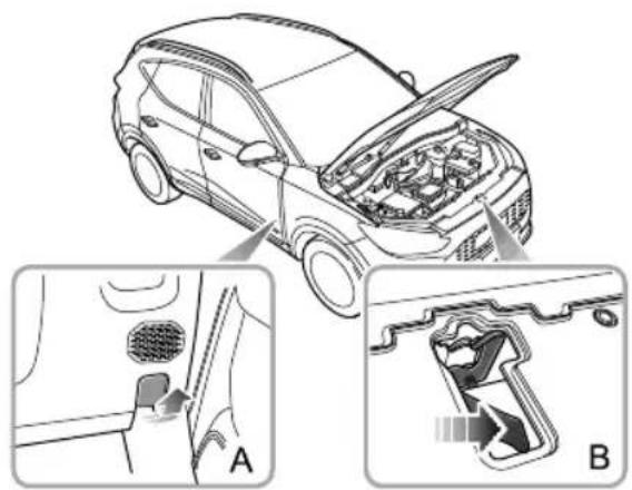
text_image
Technical diagram showing car engine compartment with labeled parts A and B, including open hood and internal components.I From the inside of the vehicle, pull the bonnet release handle (Figure A).
2Movethesafetycatchreleasehandleonthebonnet lockassemblyinthedirectionofthearrow(FigureB) toreleasethebonnetsafetycatch.
3Raisethebonnetandholditupwiththesupportrod firmly.
ClosingtheBonnet
Supportthebonnetbyonehand,releasethesupportrod usingtheotherhand,andplaceitfirmlyintothesupport rodbase.Thenholdthebonnetusingbothhandsand lowerit,allowingittodropforthelast20cm \~ 30cm tofullyclosethebonnet.
Byattemptingtoliftthefrontedgeofthebonnet,checkif thelockisfullyengagedafterclosingthebonnet.lfitisnot fullyengaged,youmustrepeattheoperation.
BonnetOpenWarning
If the bonnet is not fully engaged, when the vehicle power system is in the ON/READY position, the corresponding
MAINTENANCE
alarmiconwillbedisplayedintheinformationmessage centreoftheinstrumentpack.Ifitisdetectedthatthe bonnetisnotfullyengagedwhilstdriving,anaudible warningwillsound.
IMPORTANT
- Forsafetyreasons,thebonnetshouldbefullylatched andsecurewhendriving.Thereforeeverytimethe bonnetisopened,youmustcheckafterclosingthat thebonnetissecurelylatched,e.g.thebonnetedge isflushwiththebodyofthecar .
• Y oushouldstopthecarimmediatelywhensafety permitsandclosethebonnetifitisnotclosedfully whendriving.
- Bewareofinjurytohandswhilefullyclosingthe bonnetwithadownwardforce.
FrontCompartment

While working in the front compartment, always observethes safety precautions listed under 'Safety in the Garage', refer to 'Maintenance' in 'Maintenance' section.
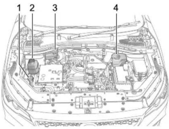
text_image
1 2 3 4I Washerfluidreservoir(bluecap)
2Batterycoolantexpansionbox (black cap)
3Brakefluidreservoir(yellow/blackcap)
4Electricdrivetransmissioncoolant expansionbox (blackcap)
MAINTENANCE
CoolingSystem
CoolantCheckandT opUp

DONOTremovethecoolantexpansiontank capwhenthecoolingsystemishot-escaping steamorhotcoolantcouldcauseserious injury.
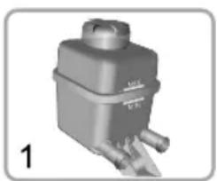
natural_image
3D rendered mechanical component with no visible text or symbols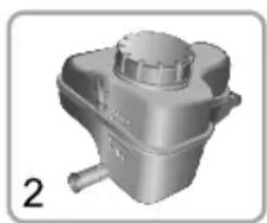
natural_image
3D rendered image of a mechanical component with a cylindrical top and flanged base, labeled '2' (no text or symbols on the object itself)I BatteryCoolantExpansionTank
2ElectricDriveT transmissionCoolantExpansionT ank
Thecoolingsystemshouldbecheckedweeklywhenthe coolingsystemiscoldandwiththecarrestingonlevel ground.Ifthecoolantlevelisbelowthe"MIN"mark, removethecoolantexpansiontankcapandtopupcoolant. Thecoolantlevelshouldnotbehigherthanthe"MAX" mark.
No preventoolarfromomingtocontact withthevehiclebodywhentoppingup.Coolantwill damagepaint.
If the coolant level falls appreciably during short period, and you suspect that ther may be leak, please seek an Authorised Repairer for service.
CoolantSpecification
Please be able to which recommend and certify. Please refer to recommend Fluid and Capacities in the "Technical Data" section.
Not the addition of corrosion inhibitors or other additive to the cooling system of this car may severely disrupt the efficiency of the system and cause parts
damage. For cooling system issues please consult an Authorised Repairer.

Coolantispoisonousandcanbefatalif swallowed-keepcoolantcontainerssealed andoutofthereachofchildren.Ifaccidental contactofcoolantbychildrenissuspected, seekmedicalassistanceimmediately.

Preventthecoolantfromcomingintocontact withtheskinoreyes.Ifthisoccurs,rinse immediatelywithplentyofwater.Ifeyes arestillred,painfuloruncomfortable,seek medicalattentionimmediately.
MAINTENANCE
Brake
Brakepads

DONOTrestyourfootonthebrakepedal whiledriving, thismayoverheatthebrakes, reducetheirefficiencyandcauseexcessive wear.
Wearratesforbrakepadsanddiscsmayvary. The recommendedminimumthicknessforbrakepadsis2mm, forfrontbrakediscsis23-25mmandrearbrakediscsis 8-10mm.
Forthefirst900miles(1500km),youshouldavoid situationswhereheavybrakingisrequired.
Remember that regular servicing is vital to ensure that all the brake components are examined for wear at the correct intervals, and replaced when required to ensure long terms safety and optimum performance during the interval prescribed in Service Portfolio.
Thecarneedstoruninfor500miles(800km)afterbrake padorbrakediscreplacement.
BrakeFluidCheckandT opUp

Brakefluidishighlytoxic, keepcontainers sealed and out of thereachofchildren. If accidental contact of brakefluidissuspected, seek medical attention immediately.

Preventrakfulbomingircontact withtheskinoreyefthisoccurs,rinse immediatelywithplentyofwatefeyes arestillred,painfuloruncomfortable,seek medicalattentionimmediately.
Thebrakefluidlevelshouldbecheckedweeklywhenthe systemiscoldandwiththecaronlevelground.
Thefluidlevelcanbeseenthroughthereservoirandshould bemaintainedbetween'MAX'and'MIN'mark.
Note: Donotallowthefluidleveltodropbelow'MIN' markorriseabove'MAX'mark.
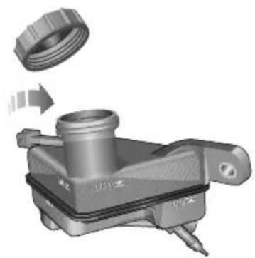
natural_image
Mechanical component diagram showing a bolt and nut assembly with a magnified inset view (no text or symbols)Note: Brakefluidwilldamagepaintedsurfaces. If you accidentally spill the brakefluid on the painted surface, soak up any spillagewith an absorbent cloth immediately and wash the area with water or car shampoo.
BrakeFluidSpecification
Usethebrakefluidrecommendedandcertifiedby themanufacturer.Referto'RecommendedFluidsand Capacities'in'T technicalData'chapter.
IMPORTANT
ReplacebrakefluidregularlyaccordingtotheService Portfolio.
MAINTENANCE
Battery
BatteryMaintenance

DONOTleaveelectriccomponentsswitched onwhennotinREADYmode, this may cause the batterytobecomeflat, resulting in the failure of the ability to set vehicle into READY mode and thereduction of battery life.

Alwaysstorebatteriesupright, tiltingmay allow the corrosivesubstances contained within the battery to leakout.

Neverattempttodismantleabattery, they aresealedunits.
The battery is located in the front compartment and is maintenance-free, therefore there is none to refill fluid.
According to the current load condition and battery status, the system may limit the power of some electrical appliances. Please ensure the vehicle is placed in READY mode as soon as possible to charge the battery.
Note: It is recommended to ensure the vehicle is placed in READY mode for half an hour every week to help extend the service life of the battery. If the vehicle is stored from more than 1 month, remove the negative terminal from the battery. Makes sure that the vehicle powers system has been turned off before connecting or disconnecting then negative terminal.
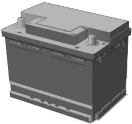
natural_image
3D rendering of a battery with two side outlets and cooling fins (no text or symbols visible)BatteryReplacement

The battery contains sulphuric acid, which is corrosive.
PleasegotoanMGAuthorisedRepairertoremoveand refitthebattery.Onlyfitareplacementbatteryofthe sametypeandspecificationastheoriginaltomaintainthe correctvehiclefunctionality.

Theusedbatteryshouldnotbediscardedatwill, foritisharmfultotheenvironment.Itmustberecycledby professionalinstitutes.PleaseconsultanMGAuthorised Repairerformoredetails.
MAINTENANCE
HighVoltageBatteryPack
Precautionsandrestrictedconditionsfor useofbattery

If the vehicle is not going to be used, parked, or stored for all time it is necessary to charge the vehicle at least once every 3 months. During this time, the High Voltage battery state of charges should not be allowed to drop below 50%.

If the battery is initial state of charge and the instrument pack displays no valid driving range, the vehicle MUST NOT be left in stored state form more than 7 days without being charged to above 50%.

Failuretofollowtheseguidelineswillresult inHVbatterydamageandinvalidatethe warranty.

DONOTattempttodismantlethebattery packoranyHighVoltagecomponents-THESEAREDANGEROUS.Anysignsof dismantlingordamagecausedbyattempts todismantlewillinvalidatethewarranty.

When using a paint curing oven please observ the following: Before and after any paint baking process, the vehicle has been broken temperature(20±2 °) for 24 hours. The vehicle can be used normally after being parked for 24 hours. The baking oven temperatures should not exceed 80 ° and the baking times should not be longer than 30 minutes.
IDONOTparkthevehicleinconditionswherethe ambienttemperatureexceeds45°Cformorethan15 days.Thiswilleffecttheperformanceandservicelife ofthehighvoltagebattery.
2Tomaintainorimprovetheservicelifeofthehigh voltagebattery,itisrecommendedthatyouuseaslow
MAINTENANCE
chargingmethodwhereverpossible,rapidcharging shouldonlybeusedforlongdistancejourneysor emergencies.
3Itisrecommendedusingthevehicleatleastoncea month.
Wherepossibleitisrecommendedthatyoucarry outaslowcharge(equalisationcharging)everymonth toextendtheservicelifeofhigh-voltagebattery pack.Thebatterymanagementsystemwillmonitor thestatusofthehighvoltagebatterypack.After monitoringforaperiodoftime,ifanequalisation chargehasnotbeencarriedoutforsometimethe messagecentreintheinstrumentpackwilldisplay 'PleaseSlow-chargetheVehicle'.Atthistimeyoumust carryoutanequalisationcharge.Foroperationmode, pleasereferto'EqualisationCharging'in'Starting& Driving'section.
4Whenthevehicleisusedforthefirsttimeorafter alongperiodofstorage,theSOCdisplayedinthe instrumentpackmaynotbeaccurate.Afullcharge isrecommendedbeforeuse.(Batterypacktype2)
5Intheeventofanaccident,damagetothehigh voltagebatteryoranyofitsrelatedcomponents,or anyrepairsmadetothehighvoltagesystemthecar mustbeinspectedbyqualifiedpersonelatanMG AuthorisedRepairer .
6Intheeventofanyaccidentorbodyrepairsbeing requiredpleaseconsultthequalifiedpersonnelatan MGAuthorisedRepairer.Therepairmayrequirehigh voltagebatteryisolationorspecialistHVcomponent removal.
IMPORTANT
Onlylyainedqualifiqersonare allowedtoworkonthehighvoltagesystemsand componentsofthisvehiclanydisassemblyof suchsystemsorcomponentsisstrictlyprohibited.
MAINTENANCE
Washer
WasherFluidCheckandT opUp

Windscreenwasherfluidisflammable.DO NOTallowwindscreenwasherfluidtocome intocontactwithnakedflamesorsources ofignition.

Whenfillingthewasherfluid,DONOTletthe washerfluidspillonpartsaroundtheengine, motor,electricdrivetransmissionoronthe paintsurfaceofthevehiclebody.Incase the washerfluidisspilledonhandsorotherparts ofthebody,pleaseimmediatelywashwith cleanwater.
Thewasherfluidisusedtocleanthewindshield.Check thewasherfluidlevelregularly.Whenthelevelofwasher fluidislow,pleasetopupthewasherfluidasinstructed. Pleaseusethewasherfluidrecommendedandcertified bythemanufacturer .Referto'RecommendedFluidsand Capacities'in"T echnicalData"chapter.
Note: DONOTuseananti-freezeorvinegar/water solutioninthewasherreservoir-anti-freezewill damagepaintworkwhilevinegarwilldamagethe washerpump.
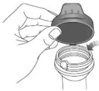
natural_image
Illustration of hands holding a coiled hose with a lid (no text or symbols)IMPORTANT
- Usethewasherfluidrecommendedandcertifiedby themanufacturer .Misuseofwasherfluidinwinter maycausedamagetothewashermotordueto freezing.
- Usingthewasherswitchwhenthereisnowasher fluidmaycausedamagetothewashermotor.
- Operatingthewiperswhenthewindscreenisdry andthereisnowasherfluidmaycausedamageto thewindscreenandwipers. Pleasespraythewasher fluidandstartthewiperswhenthereisadequate washerfluid.
WasherNozzles
Operatethewashersperiodicallytocheckthatthenozzles areclearandproperlydirected.
If thenozzleisobstructed, insertaneedleorthinmetal wireintotheholetoremovetheobstruction.
MAINTENANCE
Wipers
WiperBlades
| IMPORTANT |
| •Grease,siliconandpetrolbasedproductsimpairtheblade'swipingcapability.Washthewiperbladesinwarmsoapy waterandperiodicallychecktheircondition. |
| •Cleanthewindscreenfrequently,DONOTusewiperstoremovestubbornoringraineddirt,itwillreducetheir effectandtheirlifespan. |
| •Ifsignsofhardnessorcrackingintherubberarefound,orifthewipersleavestreaksorunwipedareasonthescreen, thenthewiperbladesshouldbereplaced. |
| •Cleanthewindscreenregularlywithanapprovedglasscleanerandensurethescreenisthoroughlycleanedbefore fittingreplacementwiperblades. |
| •Onlyfitreplacementwiperbladesthatareidenticaltotheoriginalspecification. |
| •Cleaniceandsnowfromaroundwipersandensuretheyarenotfrozenorotherwisestickingtothewindscreen beforeattemptingtooperatethem. |
MAINTENANCE
ReplacingFrontWiperBlades
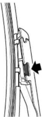
natural_image
Line drawing of a person using a tool to lift a rope, with an arrow indicating the motion direction (no text or symbols present)IWiththebonnetclosed, and within 20 seconds of switching the START/STOPSwitch to the OFF position, operatethewiperstalk switch bypassing down and releasing, the wipers willsweep and stop in the 'service position' on the windscreen.
2Liftthewiperarmawayfromthewindscreen.
3Presstheretainingclipsatbothsides(asshownin thefigure), whilstpullingthewiperbladeoutward, toremovethewiperbladefromthewiperarmand discard.
4Positionthefittingofthenewwiperbladeintotheslot ofthewiperarm.
5Pushthewiperbladetowardsthewiperarmuntilitis locatedembeddedwithaclickbeenheard.
6Placethewiperassemblybackonthewindscreen.
7T oexittheservicemodeandreturnthewipersto theparkposition,operatethewiperstalkswitchagain bypassingdownandreleasing,alternatively,setthe vehiclepowersystemtoON.
MAINTENANCE
ReplacingRearWiperBlades
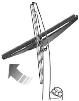
natural_image
Diagram of a mechanical device with a rotating shaft and base, showing motion direction (no text or symbols)I Liftthewiperarmawayfromtherearwindow.
2Rotatethewiperbladeasshowninthefigure,to removeitfromthewiperarmanddiscard.
3Positionthefittingofthenewwiperbladeintotheslot ofthewiperarm.Ensurethewiperbladeisproperly securedonthewiperarm.
4Placethewiperassemblybackontherearwindow.
T yre
Overview
- Newtyresmaynothavethebestadhesiveabilityatthe beginning. Therefore, drivingyourvehicleatmoderate speedandinaprudentwayatthefirst300miles, which isalsobeneficialtotheservicelifeofthetyres.
- Regularlychecktyresforsignsofdamage.DONOT removeforeignobjectssuchasscrewsornailsfromthe tyre.lfatyreshowsanysignsofdamage,pleaseensure itisinspectedbyareputabletyrefitterforadvice.
• Thevalvedustcapmustbefittedtopreventdustfrom enteringthevalve. - Ifthetyreistoberemoved,alwaysmarkthetyre/wheel orientationtoensurecorrectreinstallation.
- Storetheremovedwheelortyreinacool,dryanddark place.
The damage of atyreorrimmay happen unnoticed. If abnormal vibration or deviation is experienced, that means the tyremay have been damaged. If you suspect that tyre is damaged, pleases low down immediately, and stop your vehicle to check the tyreford damage. If you can't
seethedamagefromtheoutside,continuedrivingthe vehicleslowlytothenearestMGAuthorisedRepairerfor inspectionandservice.
T yreLife
Correcttyrepressuresandmoderatedrivingstylecan extendtyrelife.Recommendations:
- Checkthetyrepressuresatleastonceamonth, it should be carried out when the teryreiscold;
- Avoidcorneringatexcessivespeeds;
- Checktyresfrequentlyforabnormalwear;
- Whenthevehicleistobeparkedforalongtime,the vehicleshouldbemovedatleastonceeverytwoweeks topreventpermanentdeformationofthetyresdueto long-termstress.
The following factors affect theetyrelife:
TyrePressure
Incorrectpressurewillcausetheabnormalwearofthe tyre,greatlyshortentheservicelife,andhaveanadverse effectonthedrivingcharacteristicsofthevehicle.
MAINTENANCE
DrivingStyle
Excessivelyharshaccelerationandbrakingwhilstcornering willreducetyrelife.
WheelBalance
Everynewvehicleleavesthefactoryhavinghadthewheels dynamicallybalanced. Outofbalancewheelsmaybedue tomanyfactors. If wheels are outof balance, shakingor vibration of the steering mechanism may occur and the tyres may start to we are excessively. It is important to restore wheel balance as quick as possible. Each wheel should be balanced after installing anewtyreor having a tyrerepair.
WheelAlignment
Incorrectwheelalignmentcancauseexcessivetyrewear and affect vehicles safety. If the tyresshowsignsofabnormal wear, check the wheel alignment and seek advice from a MGA authorised Repairer.
CaringforyourT yres

DEFECTIVETYRESAREEXTREMELY DANGEROUS!DONOTdriveifanytyreis damaged, excessivelyworn, incorrectly inflated.

Itisrecommendedtoinstallthetyres consistentwiththeoriginapecifications. DINO Teplacthryewithyreef anythertyAlternativetyresfa differentspecification,mayadverselyaffect thehicledrivingcharacteristiand safety.Inordertoretaintheoriginalsafety characteristicsitissuggestedthatyouconsult anMGAuthorisedRepairer.
Alwaysdrivewithconsiderationfortheconditionofthe tyres,andregularlyinspectthetreadandsidewallsforany signofdistortion(bulges),cutsorwear.

If possible, protecttyresfromcontamination byoil, greaseandfuel.
T yrePressure

Beforealongdistancejourney,thetyre pressureshouldbechecked.
Check the pressures (including the spare wheel fitted) at least every month. Carry out pressure checks when the tyres are cold.
Ifitisnecessarytocheckthetyreswhentheyarewarm, youshouldexpectthepressurestohaveincreasedby30 \~ 40kPa(0.3 \~ 0.4bar).Inthiscircumstance,NEVERlet airoutofthetyresinordertomatchtherecommended pressures(cold)inthetechnicaldata.
Valves
Keepthevalvecapsfirmlysecuredtopreventdirtfrom enteringthevalve.Checkthevalveforleaks(listenfora tell-talehissing)whenyoucheckthetyrepressure.
PuncturedT yres
Y ourvehicleisfittedwithtyreswhichmaynotleakif penetratedbyasharpobject,providedtheobjectremains inthetyre.Ifyouareawareofthisoccurring,reducespeed
immediatelyanddrivewithcautionuntilthesparewheel canbefitted,orrepairsundertaken.
Notsidewaldhyriamagedr distorted,replacethyreimmediateDpanot attemptarepair.
T yreWearIndicators
Tyresfittedasoriginalequipmenthavewearindicators mouldedintothetreadpatternatseveralpointsaroundthe circumference. Whenthetreadhasworndownto 1.6mm theindicatorswillcometothesurfaceofthetreadpattern, producingtheeffectofacontinuousbandofrubberacross thewidthofthetyre.
MAINTENANCE
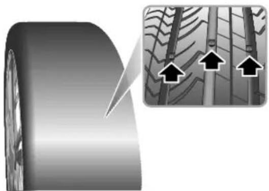
natural_image
Close-up of a tire with a magnified inset showing three upward arrows pointing to tire tracks (no text or symbols)IMPORTANT
AtyreMUSTbereplacedassoonasawearindicator becomesvisible. Otherwisetheremaybeariskof accidents.
T yreRotation
Itisrecommendedthatyouswapwheelsfromsidetoside orfronttorearatirregularintervalsinordertoequalise tyrewear.
Incasesofevenfronttyrewear,itisrecommendedto exchangethefrontandrearwheelsasshowninthefigure. Thiscanequalisetyrewear,extendtyrelife,anduniform tyrefatigue.
Swappingthedrivenwheelsdiagonallyisnotadvised, therefore,onAWDmodelsitisnotrecommendedto changeanywheelsdiagonally,fronttorearchangeis permissible.Swappingnondrivenwheelsisallowed, thereforeon2WDmodelsitispermissibletoswapwheels diagonallywhilstconsideringtheDORadvice.
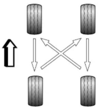
flowchart
graph TD
    A["Terr 1"] --> B["Terr 2"]
    B --> C["Terr 3"]
    C --> D["Terr 4"]
    D --> A
    style A fill:#f9f,stroke:#333
    style B fill:#f9f,stroke:#333
    style C fill:#f9f,stroke:#333
    style D fill:#f9f,stroke:#333
    note1["↑"] below A
    note2["×"] above C
tocorrectly indicate the property price at the corresponding position.
Note: Directionaltyresaremarkedwith 'directionof rotation'(DOR). Tomaintaindrivingcharacteristics, tyresmustalwaysbefittedwithindicationarrow showingthecorrect'DOR'. Whenthetyretread patternisdirectional, thewheelsmustnotbe exchangeddiagonallyorlefttorightbutcanbe exchangedfronttorear.
Note: Afteranytyre/wheelrotation, the vehicle must be driven at as speed of 25 mph for about 10 minutes
MAINTENANCE
T yre/SnowChains
Unsuitabletyre/snowchainsmaydamagethetyres, wheels, suspension, brakesorbodyworkofyourvehicle.
Please pay attention to the following requirements during usage:
- Thetyre/snowchainscanonlybefittedonthedrive wheels;
- Thethicknessoftyre/snowchainsmustnotexceed 15mm;
- Pleasealwaysobservetheinstallationandtension instructionsforthetyre/snowchains,aswellasthe speedlimitsofdifferentroads;
• Donotdrivefasterthan30mph;
•T oavoidthetyredamageandexcessivewearof thetyre/snowchains,thetyre/snowchainsmustbe removedwhiledrivingontheroadwithoutsnow.
Forthisvehicle, theonlyspecification of wheelsandtyresthatwillsupporttyre/snow chainsareasfollows:
Wheelrimsize:6.5J×16
Tyresize:205/60R16
Note: you oftendriveorsnowcoveredandcyroads, itsrecommendedtousewintertyres.Pleaseconsult anMGAuthorisedRepairerfordetails.
CleaningandVehicleCare

Observeallsafetyprecautionsoncleaning products;DoNotdrinkfluidsandkeepthem awayfromtheeyes.
Exterior
WashingY ourCar

Somehighpressurecleaningsystemswill penetratedoor, windowandsunroofseals, anddamagelockmechanisms. DONOTaim waterjetsdirectlyatcomponentsthatmight beeasilydamaged. Ensurethevehiclepower systemisOFFwhenwashingyourcar.

Donotcleanthefrontcompartmentwith highpressurewatersinceitmaydamagethe electricalsystemofthevehicle.
Inordertopreservethepaintfinishonyourcar, please observethefollowingcarepoints:
•DONOTusehotwatertowashthecar.
•DONOTusedetergentsorwashingupliquid.
• Inhotweather, DONOT was the car indirect sunlight.
- Whenusingahose, DONOTaimthewaterdirectly atwindow, doororsunroofseals, orthroughwheel aperturesontothebrakecomponents.
Ifthecarisparticularlydirty,useahosetoflushgrime and gritfromthebodywork,prioritowashing.Then,washthe carusingcoldorlukewarmwatercontainingagoodquality washandwaxshampoo.Alwaysuseplentyofwaterto ensurethatgritisflushedfromthesurfaceandnotground intothepaintwork.Afterwashing,rinsethebodywork withcleanwateranddryoffwithachamoisleather.
Cleaningtheunderside
Note: DONOTuseahighpressurehosetocleanthe frontcompartment-damagetothecar'selectronic systemsmayoccur.
Fromtimetotime, but particularly during winter months when salthas been used on theroads, use ahosetowash the underside of the car . Flush away accumulation of mud and thoroughly clean those areas wherede briscane easily collect (wheel arches and panelseams, forexample).
MAINTENANCE
IMPORTANT
- Avoidcleaningthevehicleindirectsunlight.
- Whencleaningthevehicleinwinteravoidspraying waterdirectlyontodoorlocksandpanelgapsdue toriskoficing.
- Donotuseroughspongesorclothocleanthecar, thiswilldamagethepaintworkfinish.
- Whencleaningtheheadlampsdonotuseadrycloth or sponge, useonlywarmsoapywater.
CleaningwithaHighPressureCleaner
Note: Alwaysreadthemanufacturersoperating instructions.
When using high pressure washers, always ensure there is adequate distance between the spray nozzle and any soft materials, decals or rubber seals.
Note: DONOTdirectthepressurewashernozzledirectlytowardthehighvoltagechargingpointorhighvoltagebatteryconnectionsontheundersideofthevehicle.
IMPORTANT
- Please pay attention to the operating instructions of high pressure cleaner.
• Highpressurecleaners should not be closely directed at soft part of the vehicle.
Removingtarspots
Usewhitespirittoremovetarspotsandstubborngrease stainsfromthepaintwork. Thenwashtheareimmediately withsoapywatertoremovealltracesofthespirit.
BodyProtection
Afterwashing,examinethepaintworkfordamage.Ifthe damagehasrevealedbaremetal,useacoloredprimerfirst, thenapplythecorrectcolourbasecoatandfinishoffwith alacquerpencil,ifappropriateCarryouthistreatment afterwashingbeforepolishingvaximpre extensivedamagetopaintorbodyworkmustberepaired inaccordancewiththemanufacturer'srecommendations. FailuntibivilvalidateAnti-Corrosion Warranty.Ifindoubt,askyourMGAuthorisedRepairer.
PolishingthePaintwork

DONOTusecarpolishcontainingcoarse abrasives—thesewillremovethepaintfilm anddamagetheglossfinish.
Occasionally treat the paints surface with an approved polish containing the following properties:
- Verymildabrasivestoremovesurfacecontamination withoutremovingordamagingthepaint.
- Fillingcompoundsthatwillfillscratchesandreduce theirvisibility.
- Waxtoprovideaprotectivecoatingbetweenthepaint andtheelements.
Note: If possible, avoid applying polishor wax productstowindowglassandrubberseals.
WiperBlades
Washinwarmsoapywater.DONOTusespiritorsolvent basedcleaners.
WindowsandMirrors
Regularlycleanallwindows,insideandout,usingan approvedglasscleaner.
Windscreen: In particular, clean the outside of the screen with glass clean after washing the car with wash and wax products, and before fitting new wiper blades.
Rearscreen: Cleantheinsidewithasoftcloth, usingaside tosidemotiontoavoiddamagingtheheatingelements.
Note: DONOTscrapeoruseabrasivecleanersonthe insideoftherearscreen—thiswilldamagetheheating elements.
Mirrors: Washwithsoapywater. Useaplasticscraperto removeice. DONOTuseabrasivecleaning compounds ormetalscraper.
PlasticComponents
Aplastiomponenstoublaneading conventionalcleaningmethodsandnotbetreatedwith abrasivematerials.
MAINTENANCE
PaintDamage
Anypaintdamageorstonechipsshouldbetreatedwith suitablepaint/lacquermaterialsimmediatelytoavoid invalidatingtheAntiCorrosionWarranty.
WeatherStripsandRubberSeals
Anyweatherstripsorrubberaperturesealsshouldbe treatedwithsuitablematerials(silicagel)iftheyarecleaned usingstrongdetergents,thisshouldavoidanystickingand maintaintheservicelifeoftheseal.
Wheels

Whencleaningthewheelsanymaterialsor waterthatcontactthebrakediscdirectly mayeffectbrakingefficiency.
Inordertoensurethewheelsarekeptinoptimum conditiontheyshouldbecleanedregularly.
Onlyusearecommendednon-acidicproprietywheel cleaner.Alwaysreadtheinstructionsontheproduct.
CleaningtheInterior
Plasticmaterials
Cleanplastic-faced materials with diluted upholstery cleaner, then wipewith adamp cloth.
Note: DONOTpolishdashboardcomponents—these shouldremainnon-reflective.
Carpetandfabrics
Cleanwithdilutedupholsterycleaner-testaconcealed areafirst.
Leather
Cleanleathertrimwithwarmwaterandanon-detergent soap.Dryandpolishtheleatherwithadry,clean,lint-free cloth.
Note: DONOTusepetrol, detergents, furniture creams or polishes as cleaning agents.
InstrumentPack, AudioandNavigationDisplay
Cleanwithadryclothonly.DONOTusecleaningfluids orsprays.
Extendthebelts, thenusewarmwaterandanon-detergent soaptoclean. Allowthebeltstodrynaturally; DONOT retractthemorusethecaruntiltheyarecompletelydry.
AirbagModuleCovers

DONOTallowtheseareastobefloodedwith liquidandDONOTusepetrol,detergent, furniturecreamorpolishes.
T oprotectdamagetotheairbagSRS, the following areasshouldbecleanedsparinglywithadampclothand upholsterycleanerONL Y:
•Steeringwheelcentrepad.
• Areaofdashboardcontainingthepassengerairbag.
- Areaofroofliningandfrontpillarfinisherswhich enclosethesideheadimpactprotectionmodules.
SeatBelts

DONOTusebleaches, dyesorcleaning solventsonseatbelts.
TechnicalData
312 TechnicalDataDimensions
314Weights
318 ParametersofTractionMotor
319RecommendedFluidsand Capacities
320WheelAlignment(Unladen Condition)
320 WheelsandTyres
320TyrePressure(Cold)
T echnicalDataDimensions
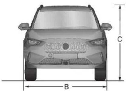
natural_image
Front view of a car with labeled dimensions B and C (no text or symbols beyond labels)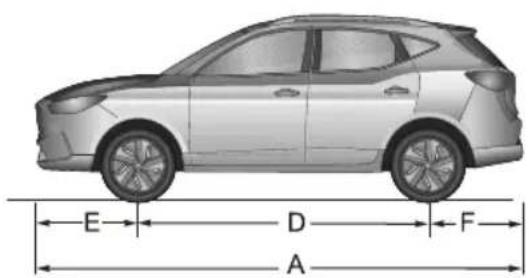
text_image
E D F A| Item,UnitsParameters | |
| OveralllengthA,mm4323 | |
| OverallwidthB,mm1809 | |
| OverallheightC(unladen),mm | 1625(bodyheight)1649(withrack) |
| WheelbaseD, mm | 2585 |
| FrontOverhangE, mm901 |
| Item,UnitsParameters | |
| RearOverhangF, mm837 | |
| FrontWheelTrack, mm | 1526 |
| RearWheelTrack, mm | 1539 |
| MinimumT urningDiameter, m | 11.2 |
Note: Vehiclelengthnotincludingthelicenseplate.
TECHNICALDATA
Note: Rearviewmirrorsandtheformedportionof tyrewalldirectlyabovethetouchdownpointarenot includedinthetotalwidth.
TECHNICALDATA
Weights
| Item,UnitsParameters | |||
| SE(51)T rophy(51) | SE&T rophy(72) | ||
| Personincab,person5 | |||
| Unladenvehicleweight (kerb),kg | 157016101620 | ||
| Grossvehicleweight,kg206020602070 | |||
| Unladenfrontaxle weight,kg | 891908914 | ||
| Unladenrearaxleweight, kg | 679702706 | ||
| Grossfrontaxleweight, kg | 101410141020 | ||
| Grossrearaxleweight, kg | 104610461050 | ||
T owingWeights
| Item,UnitsParameters | |
| T owinglimitunbraked,kg | 500 |
| T owinglimitbraked,kg | 500 |
| T owinghitchload,kg | 50 |
Note: Whentowingatraler, the vehiclespeed MUST not exceed 60 mph.
Note: Prioritotowingatrailer, please checkthereartyrepressures, inflatetoatleast20kPa(0.2bar)above the recommended pressure-DONOTallowthetyrepressuretoexceed300kPa(3.0bar), this can be dangerous.
TECHNICALDATA
T owingBarDimensions
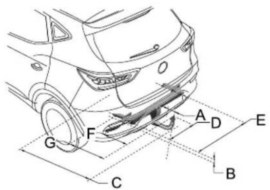
text_image
Technical diagram of a car's rear wheel assembly with labeled components A through G and reference lines.| ItemD | DimensionDescription,UnitsParameters | |
| ABumpertocentreoftowball,mm80 | ||
| B | Attachmentpointtocentrethetowball,mm | 57 |
| CWheelcentretocentreoftowball,mm912 | ||
| D | Centreoftowballtosidemember,mm465 | |
TECHNICALDATA
| Item | DimensionDescription,UnitsParameters | |
| EDistancebetweensidemembers,mm | 930 | |
| F | Centreoftowballtocentreoffirstattachmentpoint,mm321 | |
| G | Centreoftowballtocentreofsecondattachmentpoint, mm | 460 |
TECHNICALDATA
ParametersofT ractionMotor
| Item,Units | ParameterValues | |
| BatteryPackT type1 BatteryPackT type2 | ||
| T ractionmotortypeThree-phasepermanentmagnetsynchronousmotor | ||
| ContinuousPower/MaximumNetPower,kW75/13073/115 | ||
| PeakT orque,Nm | 280280 | |
| RatedSpeed/MaximumSpeed,rpm9000/150008000/15000 | ||
| WindingType | △ | |
| WaterproofGrade | ||
RecommendedFluidsandCapacities
| Name | GradeCapacity | |
| Electricdrivetransmissioncoolant,L | Glycol(OAT) | 4.8 |
| High-voltagebatterypackcoolant,L | 5.6 | |
| Electricdrivetransmissionoil,L | ShellIE-FluidsE6iX(SL2808)0.9 | |
| Brakefluid,LDOT40.85 | ||
| Windshielddetergent,L | ZY -VIII | 4 |
| Airconditioningrefrigerant,gR1234yf540±20 |
TECHNICALDATA
WheelAlignment(UnladenCondition)
| ItemParameter | ||
| Front | Camberangle | -0^35' ± 45' |
| Castorangle | 4^01' ± 45' | |
| T oe-in(T otal) | 0^8' ± 15' | |
| Kingpininclination | 12^04' ± 45' | |
| Rear | Camberangle | -1^15' ± 45' |
| T oe-in(T otal) | 0^24' ± 20' | |
T yrePressure(Cold)
| WheelsUnladen | |
| FrontWheels | 280kPa/2.8bar/4 l psi |
| RearWheels | 280kPa/2.8bar/4 l psi |
WheelsandT yres
| Wheelsize | 7.0J×17 |
| T yresize | 215/55R1794V |
Appendix
322RemovableTowBar
APPENDIX
RemovableT owBar
T owBarOperatingInstructions
Safety:
Operationofthedetachabletowbarshouldonlybe performedbyhand,neverusehandtoolstoooperatethe lockingmechanism.
If the trailer is fitted with a security cable or brakeable it must be attached to the dedicated connection hole in the fixed part of the window bar.
Whenastabilisercouplingisinstalledonthetrailernever usegreaseonthetowball.
Alwaysremovethedetachabletowballwhennotinuseif itobscurestheregistrationplate.
Preparation:
Removetowballcover.
Ensurethetowballiscleanandfreefromdirtanddebris.
Ensurethetowballisinthe'springposition'(seepicture 3.1).
Thetowballisinthespringpositionif:
•Theoperatinghandleispushedincompletelyandno colourindicationisshowninsidetheindicationareaof theoperatinghandle.
- Thesliderispulledfullytowardsthetowball(shownin picture3.1).
- Itisnotpossibletolockthesystemwiththesupplied lockingkeys(seepicture5.2).
ThetowballisNOTinthespringpositionif:
•Theoperatinghandleispoppedoutandshowsared fieldintheindicationareaoftheoperatinghandle(see picture3.1)
- Thesliderispushedouttowardsthetowball(thepart isindicatedbyinpicture3.1).
- Itispossibletolockthesystemwiththesuppliedkeys (seepicture5.2).
T oplacethetowballinthespringposition:
- Unlockthetowball(seepicture6.1)
- Pushtheoperatinghandleinwards, rotateinaclockwise direction (whilstpushinginwards) until the handle remains in position (seepicture 3.2). Ifunsurerepeat operation.
Note: If atowball cannot be tensioned into the spring position it cannot and MUST NOT be used.
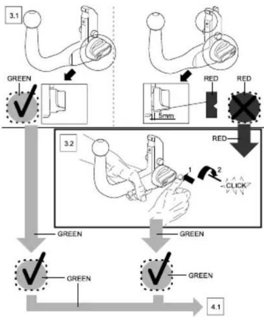
flowchart
graph TD
    A["3.1"] --> B["GREEN ✓"]
    B --> C["1.5mm"]
    C --> D["RED RED"]
    D --> E["3.2"]
    E --> F["GREEN ✓"]
    F --> G["GREEN ✓"]
    G --> H["4.1"]
    style A fill:#f9f,stroke:#333
    style B fill:#ccf,stroke:#333
    style C fill:#cfc,stroke:#333
    style D fill:#fcc,stroke:#333
    style E fill:#ffc,stroke:#333
    style F fill:#cff,stroke:#333
    style G fill:#ffc,stroke:#333
    style H fill:#cfc,stroke:#333
Attachment:
Beforeattachingthetowballtothecarpleaseremovethe coverfromthehousing(seepicture4.1).
- Inserttowball(thatmustbeinthespringposition)fully intothehousing.
- Holdthetowballinposition,keepingyourhandsaway fromtheoperatinghandle,useaslightforcetopullat thetowballasshowninpicture4.3.
• The unlockingpinwilltriggerthelockingmechanismand thelockingprocesswillautomaticallytakeplace.
•Alwayscheckthetowballiscorrectlyinstalled, this can berecognised by:
•Theoperatinghandlepopsoutandaapproximategap of5millimeterswillbevisiblebetweenthetowballand theoperatinghandle(seepicture5.1). - Agreenfieldwillbevisibleintheindicationareaofthe operatinghandle(seepicture5.1).
- Thetowballcanbelockedusingthesuppliedkeys(see picture5.2). Thiscanonlybedonewhenthehandle haspoppedoutcompletely,afterthisthehandlecanno longerbepushedinandthetowballcannotbereleased (remembertoremovethekeys).
APPENDIX
- Checkthetowballforsecurity-noplayshouldbe evident.
Thetowballisnowreadyforuse.
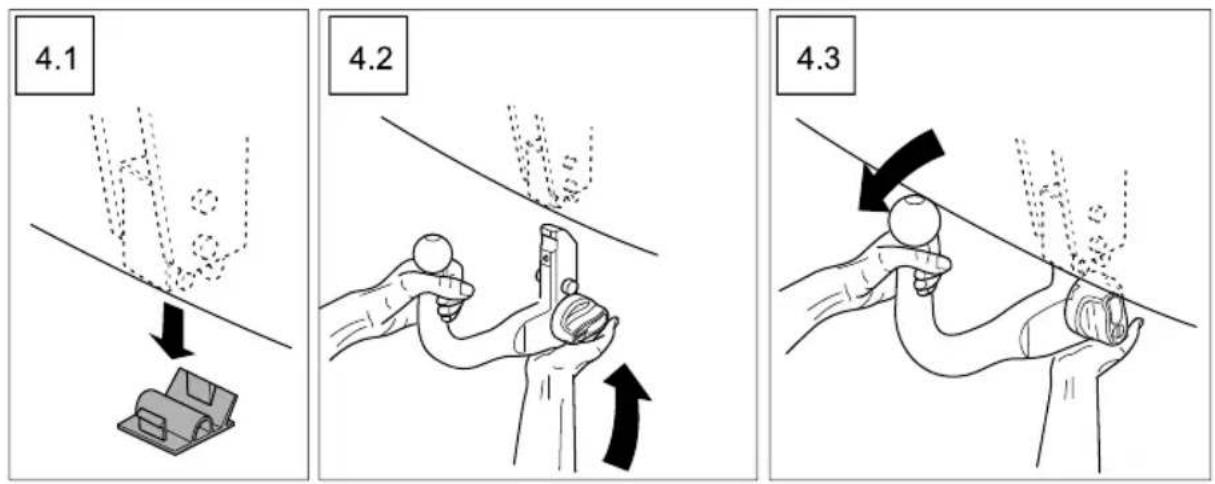
CarePoints
•Alwayscheckthetowballforcorrectmountingevery timepriortouse.
- Neverattempttoattach/detachatowballwhilst trailer/accessoryattached.
•Alwayskeepthetowballcleanandfreefromdebris,do notcleanwithhighpressurewasher.
- Neveruseatowballthatassignsofdamage,excessive wearormodification.
- Neveruseatowballthathasbeeninstalledbyanyother methodthan'handpressure'.
Removal
Always disconnect the trailer/accessory and safetyable prioritotow ball removal.
- Unlockthedetachabletowballbyturningthelocking keyclockwiseusingyourthumbandforefinger(see picture6.1).
-
Holdthetowballwithyourlefthand,pushthe operatinghandlefullyinwardsandturnclockwiseuntil theoperatinghandleremainsinposition(seepicture 6.3).
-
Thetowballcannowberemovedfromthehousingin adownwardmotion(seepicture6.4).WARNING,this itemisheavy,donotallowittodrop.
• Refittheplasticcoverintothehousing(seepicture6.5).
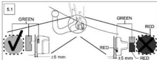
text_image
5.1 GREEN ±5 mm GREEN RED RED ±5 mm RED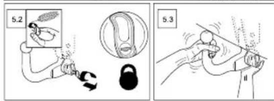
text_image
5.2 5.3APPENDIX