ZS (2018) - Automotive MG - Free user manual and instructions
Find the device manual for free ZS (2018) MG in PDF.


User questions about ZS (2018) MG
0 question about this device. Answer the ones you know or ask your own.
Ask a new question about this device
Download the instructions for your Automotive in PDF format for free! Find your manual ZS (2018) - MG and take your electronic device back in hand. On this page are published all the documents necessary for the use of your device. ZS (2018) by MG.
USER MANUAL ZS (2018) MG
VehicleIdentificationInformation....4
Vehicle identification....4
VehicleIdentificationLabel....5
I InstrumentsandControls....7
Instruments and Controls....8
InstrumenPack....10
InstrumentPack-ColourDisplayA * 10
InstrumentPack-ColourDisplayB *
InformationCentre....13
InformationCentre-ColourDisplayA * 13
InformationCentre-ColourDisplayB * 21
CONTENTS
Warning lights and indicators....29
LightandSwitches....37
MasterLightingSwitch....37
Headlamp Levelling Manual Adjustment....39
FogampSwitch....40
DirectionIndicator/MainBeanSwitch....41
Hazard Warningamp....42
WipersandWashers....43
WindscreenWiperOperation....43
ProgrammedWash/Wipe....44
RealWindowWiperOperation....45
SteeringSystem....47
Adjustment Steering Column....47
Electric Power Steering....48
Horn....49
Mirrors....50
DooMirrors....50
InteriorRearviewMirror....52
Sunvisor....53
CONTENTS
Windows....54
PowerOperatedWindowSwitch....54
WindowOperation....54
Sunroof ^* 56
Instructions....56
SunrooOperation....57
InteriorLights....61
PowerSocket....62
Storage Devices....64
Instructions....64
GlovoBox....64
CardBox....65
CentreConsoleArmresBox....65
Loadspace....66
CupHolder....67
CentreConsole Cup Holder(EPB)....67
CentreConsole Cup Holder(IPB)....67
RoofLuggageRack \* 68
MaximumAuthorisedLoadotheRoof....68
CONTENTS
PeriodicalCheck....68
2AirConditioningandAudioSystems....69
Ventilation....70
A/Particle/PollerFilter....71
Vents....71
Electronic TemperatureControl....73
InfotainmenScreenControlInterface....73
ControPanel....76
A/∅display....78
EntertainmenPlayer....79
Important Safety Information....79
Caution for Using Screen....80
AdditionaNotes....80
Basic Operations....81
Bluetooth|Phone....87
Entertainment....94
Vehicle-MobilePhoneInterconnection * 102
A/C....103
VehicleSettings....103
CONTENTS
Settings....104
3Seats&Restraints....107
Seats....108
Overview....108
HeadRestraints....108
Fron6eats....109
ReaSeats....III
FrontSeatHeating * .......III
SeaBelts....113
Protection Provided by Sea Belts....114
Wearing Sea Belts....115
Children and Sea Belts....119
SeaBelPre-tensioners....120
SeaBelChecksMaintenanceandReplacement....121
AirbagSupplementaryRestraintSystem....124
Overview....124
AirbagDeployment....125
Conditions Which Airbag Will No Deploy....128
Disabling the Passenger Airbag....129
CONTENTS
Servicand ReplacementAirbags....131
DisposabAirbags....132
ChildRestraints....133
Important Safety Instructions about Using Child Restraints....133
Child Restraints Groups....136
ApprovedChildRestrainPositions....139
4Starting&Driving....145
Keys....146
Overview....146
ReplacingBattery....147
ChildProoLocks....151
AlarmSystem....152
Enginemmobilisation....152
Anti-thefsystem....153
Tailgate....157
Starting and Stopping Engine....159
IgnitionSwitch ( KeyStart ) * 159
START/STOPSwitch(KeylessStart) * 160
CONTENTS
StartingtheEngine ( KeyStart ) * 162
StartingtheEngine ( KeylessStart ) * 163
PrecautionfoStartinghEngine....165
Stopping Engine....166
EconomicalandEnvironmentalDriving....167
Running-in....167
Environment Protection....167
Economic Driving and Maintenance....167
DrivingSpecialEnvironment....169
CatalyticConverterandParticulateFilter....170
FueSystem....172
FueRequirements....172
FueFiller....173
Refueling....173
AutomaticT transmission....174
Instructions....174
GeaShift....174
Driving the Hill....177
ControMode....178
CONTENTS
ManualT transmission ^* 181
5-speedManualT transmission ^ .....181
6-speedManualT transmission ^ 182
BrakeSystem....184
FooBrake....184
Electronic Brake Force Distribution(EBD)....185
ElectroniBrakeAssistance(EBA)....185
HillHoldControl(HHC)....185
HilDescenContro(HDC)....187
Anti-locBrakSystem(ABS)....189
AutoHold * 191
Emergency Braking Hazard Warning lights Control(HAZ)....193
ActiveRolloveProtection(ARP)....193
ParkingBrake 194
ElectronicParkingBrake(EPB) * 195
AutomatedStop/Start—IntelligentFuelSavingSystem....197
AutomatiShutdownEngine....198
Engine AutoStop Conditions....198
Stop/StarProhibited....198
CONTENTS
AutomatiEnginStart....199
StartInhibition....199
StalAssist....200
Battery....200
AutomatedStop/StartIntelligenFueSavingSystemFailure....201
StartelInoperativeSeriousBatteryCapacityLoss....201
StabilityControlSystem(SCS)andTractionControlSystem(TCS)......202
CruiseControSystem....204
ActiveSpeedLimit(ASL)System....207
Activate....207
KickDown....208
SuspendingASL 208
ResumingASL....208
OvershoobTargeSpeedandWarning....209
ParkingAidSystem * 210
UltrasonicSensorParkingAid * 210
360PanoramicImagingSystem 212
RearDriverAssistanceSystem * 214
SystemOverview....214
CONTENTS
SwitchinghSystemFunctionOn/Off....216
SystemFunctions....216
T yrePressureMonitoringSystem(TPMS)......220
LoadCarrying....222
Loadspace....222
InternalLoading....223
GeneralT owing Safety....223
5EmergencyInformation....225
HazardWarningDevices....226
Hazard Warning lights....226
Warning triangle....226
EmergencyStarting....228
UsingBoosterCables....228
StartingheCar....228
VehicleRecovery....230
TowingforRecovery....230
TransporterTrailerwithRope....233
T yreRepairandWheelReplacement....235
CONTENTS
Toolidentification....235
TyrRepair....235
ChangingaWheel * 238
FuseReplacement....242
Fuse....242
FusBox....242
PassengerCompartmenFuseBox....243
FronCompartmenFuseBox....246
BulbReplacement....250
BullSpecification....250
BullReplacement....251
&Maintenance....259
Maintenance....260
Routine Maintenance....260
Bonnet....264
OpeninghBonnet 264
Closingh Bonnet 264
BonneOperWarning....264
CONTENTS
EngineCompartment......266
1.5EngineCompartment....266
1.0 UT urbocharged Engine Compartment....267
Engine....268
EngineOil....268
Engine Oil Leve Check and Top Up....268
EngineOIspecification....269
CoolingSystem....270
CoolanCheclandTopUp....270
Coolan&pecification....270
Brake....272
BrakePads....272
BrakeFluidCheckandTopUp....272
BrakeFluidSpecification....273
Battery....274
Battery Maintenance....274
Battery Replacement....274
Washers....276
WindscreenWasherChecklandTopUp....276
CONTENTS
Washer Nozzles....277
WasherFluidSpecification....277
Wipers....278
WipeBlades....278
ReplacingFrontWipeBlades....279
ReplacingRealWipeBlades....280
Tyres....281
Overview....281
NewTyres....281
DirectionalT yres....281
TyrdLife....281
TyrePressure....282
Drivingstyle....282
WheeBalance....282
WheelAlignment....282
CaringoY ourT yres....282
TyrePressure....283
Valves....283
PuncturedTyres....283
CONTENTS
TyreWeaIndicators....283
ReplacementTyres....284
WheeFitmenRotation....284
SnowChains....285
CleaningandVehicleCare....287
ExternaCar....287
CleaningInterior 290
echnicaData....293
TechnicaDataDimensions....294
Weights....296
TowingWeights....296
Towing Bar Dimensions....297
MajorParametersEngine....299
RecommendedFluidsandCapacities....301
WheelAlignment(UnladenCondition)....302
WheelsandT yres....302
TyrePressure(Cold)....302
CONTENTS
8Appendix....303
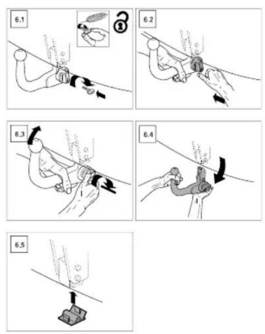
RemovableTowBar....304
TowBarOperatingInstructions....304
Introduction
TheOwner'sHandbook
This handbook describes all of the vehicles and standard equipments specification within the model range. Some of the information therefore, may not apply to your particular car.
Alwaysrememberthatifyouhaveanyqueriesconcerning theoperationorspecificationofyourcar,yourMG AuthorisedRepairerwillbegladtoadviseyou.
The illustrations in the Owner's Handbook are for reference only.
The information presented in this manual may vary slightly depending on vehicle configuration, software version and sales area.
StatusatTimeofPrinting
MGoperatesapolicyofconstantproductimprovement andthereforereservestherighttochangespecifications withoutnoticeatanytime.Whilsteveryeffortis madetoensurecompleteaccuracyoftheinformation inthispublication,noliabilitiesforinaccuraciesorthe
consequencesthereof,includinglossordamageto property,orinjurytopersons,canbeacceptedbythe manufacturerorMGAuthorisedRepairerwhosupplied thepublication,exceptinrespectofpersonalinjurycaused bythenegligenceofthemanufacturerorMGAuthorised Repairer.
Warranty
Pleaseconsultmg.co.ukforthevehiclewarrantytermsand conditions,warrantystatementandexemptions.
PREFACE
SymbolsUsed
The following symbols used within the handbook can your attention to specific types of information.
Warning

This warningsymbolidentifies procedures that must be followed precisely, or information that must be considered with great care, inordertoreducetherisk of personal injury or serious damage to the car.
Important
IMPORTANT
Thestatementsstatedheremustbefollowedstrictly, otherwiseyourcarcouldbedamaged.
Note
Note: This describes helpful information.

Thissymbolindicatespartsdescribedmustbe
disposedofbyauthorisedpersonsorbodiestoprotect theenvironment.
Asterisk
Anasterisk(*)appearingwithinthetext,identifiesfeatures oritemsofequipmentthatareeitheroptional,orareonly fittedtosomevehiclesinthemodelrange.
IllustrationInformation

Identifiescomponentsbeingexplained.

Identifies movement of components being explained.
InanEmergency
IMPORTANT
Rememberthebreakdownsafetycode
Ifabreakdownoccurswhiletravelling:
- Whereverpossible,consistentwithroadsafetyand trafficconditions,thecarshouldbemovedoffthe mainthoroughfare,preferablyintoalay-by.lfa breakdownoccursonamotorway,pullwelloverto theinsideofthehardshoulder.
- Switchonhazardlights.
•Ifavailable,positionawarningtriangleoraflashing amberlight150to500ftbehindyourvehicletowarn approachingtraffic.Noteitisalegalrequirement ofsomecountriesthatawarningtriangleiscarried inthevehicle,ifindoubtconsultthelocalhighways agencyforfurtherinformation. - Considerevacuatingpassengersthroughnearside doorsontothevergeasaprecautionincaseyour vehicleisaccidentallystruckbyothertraffic.
PREFACE
VehicleIdentificationInformation
VehicleIdentification
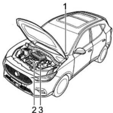
text_image
Technical diagram of a car with labeled parts, showing engine compartment and structural componentsI VehicleIdentificationNumber(VIN)
2EngineNumber
3T transmissionNumber
AlwaysquotetheVehicleIdentificationNumber(VIN) whencommunicatingwithyourMGAuthorisedRepairer .
If the engine or transmission is involved, it may be required to provide the identification numbers of these assemblies.
VehicleIdentificationLocation
VehicleIdentificationNumber(VIN)
- Stampedonaplatevisiblethroughthebottomlefthand cornerofthewindscreen;
•Ontheidentificationplate;
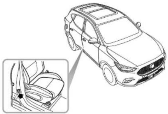
• Onthefloorunderthefrontrighthandseat;
- Ontheinnersideofthetailgatevisiblebyopeningthe tailgate.
Note: The DLC is located in the driver footwell at the base of the fasci panel on the RH side. The VIN information can be extracted from the vehicle using the approved diagnostic equipment.
EngineNumberLocation
Stampedonthefrontrightofthecylinderblock(Viewfrom thefrontoftheengine).
TransmissionNumberLocation
Onthesurfaceofthetransmissionhousingintheengine compartment. Thetransmissionnumbersofcertain modelsareonlyvisiblebyraisingthevehicle,please contactalocalAuthorisedRepairer.
VehicleIdentificationLabel
hevehicleidentificationlabelcontainsthefollowing information:
•T ypeApprovalNumber;
-EngineT ype;
•VehicleIdentificationNumber(VIN);
•GrossVehicleWeight;
•GrossT rainWeight *;
•MaxFrontAxleWeight *;
•MaxRearAxleWeight *;
- PaintCode
•T rimCode
PREFACE
LocationofVehicleIdentificationLabel
The identification label is located at the lower side of right pillarB
natural_image
Line drawing of a car showing the front and side views of the seat (no text or symbols)InstrumentsandControls
8InstrumentsandControls
10 InstrumentPack
I 3InformationCentre
29WarningLightsandIndicators
37LightsandSwitches
43 WipersandWashers
47SteeringSystem
49Horn
50 Mirrors
53Sunvisor
54Windows
56Sunroof *
61 InteriorLights
62 PowerSocket
64 StorageDevices
67CupHolder
68RoofLuggageRack
INSTRUMENTSANDCONTROLS
InstrumentsandControls
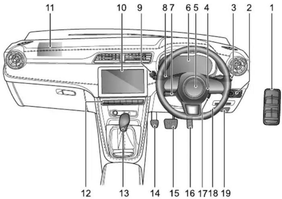
text_image
11 10 9 8 7 6 5 4 3 2 1 12 13 14 15 16 17 18 19INSTRUMENTSANDCONTROLS
IPowerWindowSwitch
2ExteriorRearviewMirrorandHeadlampLeveling Switch
3WiperStalkSwitch
4HornButton
5DriverAirbag
6InstrumentPack
7 CruiseControl/ASLStalkSwitch
8Indicator/MainBeamStalkSwitch
9START/STOPSwitch(KeylessStart)
10InfotainmentSystem
IIFrontPassengerAirbag
12Infotainment/AirConditioningControlSwitch
13GearShiftLever
14ClutchPedal *
15BrakePedal
16AcceleratorPedal
I7START/STOPSwitch(KeyStart)
18BonnetReleaseHandle
19FuelFillerFlapReleaseHandle
INSTRUMENTSANDCONTROLS
InstrumentPack
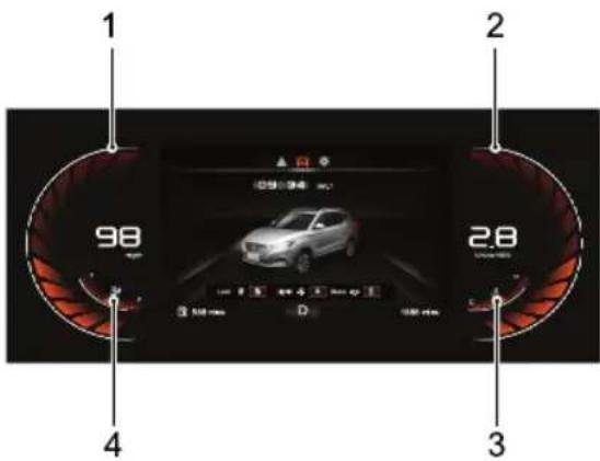
InstrumentPack-ColourDisplayA
text_image
1 2 98 28 4 3Speedometer(1)
Indicates the vehicle speed in km/h.
Tachometer(2)
Indicateshenginspeed×1000pm.
IMPORTANT
T protecthengin rondamage ever allow the point to remain the effect of gaug for prolonge periods.
EngineCoolantTemperatureGauge(3)
Indicateshengincoolantemperature.
FueGauge(4)
Indicates the quantity of fuel the tank.
Theovuevarningampwilluminatyellowoflash whertheueremainingthuetanklow.
IMPORTANT
If the dowel warning ampilluminates please refueals early possible.
Indicate that eufille is located the
rightside the vehicle.
INSTRUMENTSANDCONTROLS
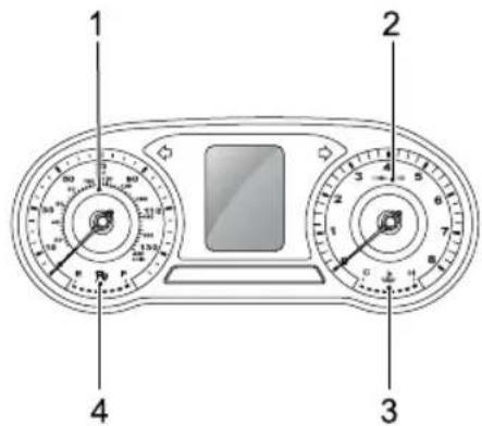
InstrumentPack-ColourDisplayB
text_image
Diagram of a car dashboard with labeled parts including front, back, and interior gaugesSpeedometer(I)
Indicates vehicle speed mph and km/h.
T achometer(2)
Indicate the engine speed, 1000pm.
IMPORTANT
T protectengine on damage, ever allow the point to remain the effect of gaug for prolonge periods.
EngineCoolantT emperatureGauge(3)
Indicateshengincoolantemperature.
FuelGauge(4)
Indicates the quantity of fuel in the tank.
Theovue warningampvilluminate yellowoflash wherthéueremainingthéuetankisow.
IMPORTANT
If the dow fuel warning ampilluminates please refue as early possible.
Indicates that eufille is located the
rightside the vehicle.
INSTRUMENTSANDCONTROLS
Note: Depending on the vehicle options, software version and market area, the information displayed may vary slightly.
Note: The units can be changed using the entertainmentsystem. Please use the operation steps: Setup-Display-Units
INSTRUMENTSANDCONTROLS
InformationCentre
InformationCentre-ColourDisplayA \*
text_image
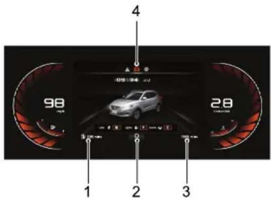
98 2.8 1 2 3 4The information centre provides the following:
RangeT Empty
GeaDisplay and GeaShiftIndication
BotaMileage
GeneralInformation
RangeT Empty
Display the estimated mileage of the vehicle at travel before he is a good empty.
GearDisplayandGearShiftIndication
Displaysheurrengeapositionotheransmission(P
arrowisdisplayed other right of the gear position indicator, advises drivershigeawhtheonditions
permHEP displayed indicateshaullhas
beendetectedwithtransmissionPlease seek MG
Authorised Repairer as soon impossible Referto "Starting & Driving" section.
TotaMileage
Displays the total driving mileage of the vehicle.
GeneralInformation
The general information function are selected follows:
INSTRUMENTSANDCONTROLS
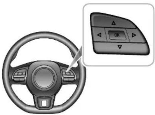
- PresstheUP/DOWN/LEFT/RIGHTbuttonontheright handmultifunctionsteeringwheelswitchtoshiftthe displayitems.
- PresstheUP/DOWNbuttonontherighthand multifunctionsteeringwheelswitchtomake adjustment.
- PresstheOKbuttonontherighthandmultifunction steeringwheelswitchtoconfirmorlongpressOK buttontoreset.

natural_image
Interior view of a car steering wheel with a control panel showing OK button (no text or symbols on the dashboard)Generalinformationprovidesthefollowing:
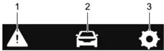
text_image
1 2 3I WarningInformation
2T ripComputer
3Setting
WarningInformation
Displaythewarninginformationorimportantnotesthat arecurrentlyrelevanttothevehicle.
TripComputer
T ripcomputerfunctionscontainthefollowing:
- DefaultPagdisplaysthecurrentstatusofthelocks, lightsanddoors.
- CurrentJourney: displaystherange, duration, average speed-average consumption since startup.
INSTRUMENTSANDCONTROLS
Thesevalueswillberesetafteraperiodofpoweroff. ItcanalsoberesetbylongpressingtheOKbuttonontherighthandmultifunctionsteeringwheelswitch.
•AccumulatedT otal:displaystherange,duration,averagespeedandaveragefuelconsumptionsincethe lastreset.ItcanberesetbylongpressingtheOK buttonontherighthandmultifunctionsteeringwheel switch.
- T yrePressures: display the current ty repressured data foreachwheel.
- BatteryVoltage:displaythe12VBatteryVoltage.
Setting
Brightness
Displaysthecurrentlevelandallowsadjustmentofthe backlightbrightness.
SpeedWarning
Allowsthesettingoftheover-speedalarmthreshold.
NextService
Displaysandfacilitatestheresetofthecurrentvehicle maintenanceinformation.
WarningMessage
Warning messages prompt display the information and strume park. communications are displayed in 'popup' messages, these can be divided into the following categories:
- OperatingInstruction
•SystemStateInstruction
•SystemMalfunctionAlert
Please follow the instructions displayed in the 'popup' message or in the case of awarning message, pleaserefer to therelevant section of the owners manual to follow the correct instructions.
The following re selection of warning messages that may appear in the information centre.
INSTRUMENTSANDCONTROLS
| WarningMessageProcedure | |
| CruiseControl Fault | Indicatesthatthecruisecontrol systemhasdetectedafault.PleaseconsultanMGAuthorised Repairerassoonaspossible. |
| ActiveSpeed LimiterFault | Indicatesthattheactivespeed limitsystemhasdetectedafault.ContactanMGAuthorised Repairerassoonaspossible. |
| EngineCoolant TemperatureHigh | Highenginecoolanttemperature couldresultinseveredamage.Assoonasconditionspermit,safelystopthevehicleandswitch offtheengineandcontactanMGAuthorisedRepairerimmediately. |
| EngineCoolant Temperature SensorFault | Indicatesthattheenginecoolant temperaturesensorhasfailed.Assoonasconditionspermit,safelystopthevehicleandswitch offtheengineandcontactanMGAuthorisedRepairerimmediately. |
| WarningMessageProcedure | |
| LowOilPressure | Indicatesthattheoilpressure istoolow,whichmayresultin severeenginedamage.Assoon assafetypermits,stopthecar, switchofftheengineandcheck theengineoillevel.Contactan MGAuthorisedRepairerassoon aspossible. |
| EngineFault | Indicatesthatafailurehas occurredthatwilleffectengine performanceandemissions. ContactanMGAuthorised Repairerassoonaspossible. |
| CheckEngine | Indicatesthatafailurehas occurredthatmayseverely damagetheengine.Assoonas conditionspermit,safelystopthe vehicle,switchofftheengine andcontactanMGAuthorised Repairerimmediately. |
INSTRUMENTSANDCONTROLS
| WarningMessageProcedure | |
| StopStartSystem Fault | IndicatesthattheStop/Start intelligentfuelsavingsystemhas detectedafault.PleaseconsultanMGAuthorisedRepaireras soonaspossible. |
| ClutchSwitchFault | Indicatesthattheclutchswitch hasdetectedafault.Please consultanMGAuthorised Repairerassoonaspossible. |
| GasolineParticular FilterFull | Indicatesthatthegasoline particularfilterisfull.Please consultanMGAuthorised Repairerassoonaspossible. |
| IgnitionSystem Fault | Indicatesthattheignitionsystem hasdetectedafault.Please consultanMGAuthorised Repairerimmediately. |
| WarningMessageProcedure | |
| StartStopButton Fault | IndicatesthattheStartStop buttonhasdetectedafault.PleaseconsultanMGAuthorised Repairerimmediately. |
| PassiveEntryFault | Indicatesthatthepassive keylessentry(PKE)functionhas detectedafault.Pleaseconsult anMGAuthorisedRepaireras soonaspossible. |
| ABSFault | Indicatesthattheanti-lock brakesystem(ABS)hasfailed andtheABSfunctionisabout tobedisabled.Pleaseconsult anMGAuthorisedRepairer immediately. |
INSTRUMENTSANDCONTROLS
| WarningMessageProcedure | |
| BrakeFault | Indicatesthatthebrakefluid couldbeloworafaulthas beendetectedintheElectronic Brake-forceDistribution(EBD) system.Assoonassafety permits,stopthecar,switch offtheengineandcheckthe brakefluidlevel.ContactanMG AuthorisedRepairerassoonas possible. |
| StabilityControl Fault | Indicatesthatthestabilitycontrol systemhasdetectedafault.PleaseconsultanMGAuthorised Repairerimmediately. |
| T ractionControl Fault | Indicatesthatthetraction controlsystemhasdetectedafault.PleaseconsultanMG AuthorisedRepairerimmediately. |
| WarningMessageProcedure | |
| EPBSystemFault | Indicatesthattheelectronic parkingbrakesystem(EPB)has detectedafault.PleaseconsultanMGAuthorisedRepaireras soonaspossible. |
| ParkBrakeForceNotEnough | Indicatesthatthereisanissue withtheelectronicparking brake,itmaynotbeableto provideadequateclampingforce.ContactanMGAuthorised Repairerassoonaspossible. |
| AutoholdFault | IndicatesthattheAutohold Systemhasdetectedafault.PleaseconsultanMGAuthorised Repairerassoonaspossible. |
| HillDescentControlFault | Indicatesthatthehilldescent controlsystemhasdetectedafault.PleaseconsultanMGAuthorisedRepairerassoonas possible. |
INSTRUMENTSANDCONTROLS
| WarningMessageProcedure | |
| EPSPerformance Reduced | Indicatesthatthelectricpower steeringsystemhasageneral failureandthatthesteering performancehasbeenreduced. Assoonasconditionspermit, safelystopthevehicleandswitch offtheengine.Afterashort while,starttheengine,drive thevehicleashortdistance andmonitortheoperationof thesteering,ifthemessageis stilldisplaydorthesteering assistancereducedplease contactanMGAuthorised Repairerimmediately. |
| EPSAssistance Failure | Indicatesthatthelectricpower steeringsystemhasfailed.Please consultanMGAuthorised Repairerimmediately. |
| WarningMessageProcedure | |
| SteeringAngleFault | Indicatesthatthesteeringangle sensorhasfailed.Pleaseconsult anMGAuthorisedRepaireras soonaspossible. |
| SteeringAngle Uncalibrated | Indicatesthatthesteeringangle sensorisnotcalibrated.Please consultanMGAuthorised Repairerassoonaspossible. |
| ESCLFault | Indicatesthatafaulthasbeen detectedwiththeElectronic SteeringColumnLock(ESCL). Assoonasconditionspermit, safelystopthevehicleandswitch offtheengine.ContactanMG AuthorisedRepairerassoonas possible. |
| FuelSensorFault | Indicatesthatfuelsensorhas detectedafault.Pleaseconsult anMGAuthorisedRepaireras soonaspossible. |
INSTRUMENTSANDCONTROLS
| WarningMessageProcedure | |
| AirbagFault | IndicatesthattheAirbagsystemhasdetectedafault.Assoonasconditionspermit,safelystopthevehicleandswitchofftheengineandcontactanMGAuthorisedRepairerimmediately. |
| FrontLeft/FrontRight/RearLeft/RearRightTyreSensorBatteryLow | IndicatesthattheTyrePressureMonitoringsystemhasdetectedthatatyrepressuresensorhasalowbattery.PleaseconsultanMGAuthorisedRepairerassoonaspossible. |
| TPMSFault | Indicatesthatthetyrepressuremonitoringsystemhasdetectedafault.PleaseconsultanMGAuthorisedRepairerassoonaspossible. |
| WarningMessageProcedure | |
| 12VBatteryChargingSystemFault | Indicatesthatthe12Vbatterychargingsystemhasfailed.PleaseconsultanMGAuthorisedRepairerimmediately. |
| RearDriveAssistSystemFault | Indicatesthatthereardriveassistsystem(RDA)hasdetectedafault.PleaseconsultanMGAuthorisedRepairerassoonaspossible. |
INSTRUMENTSANDCONTROLS
InformationCentre-ColourDisplayB
text_image
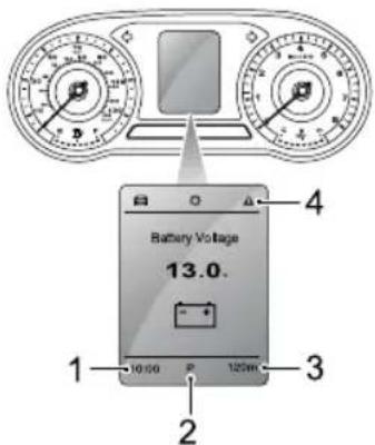
Battery Voltage 13.0. 10:00 P 120kV 2 3 4DigitalClock
GeaDisplay and GeaShift Indication
BotaMileage
GeneralInformation
DigitalClock
Display the current time of digital form.
GearDisplayandGearShiftIndication
Display the currengeaposition other transmission(P
arrowsdisplayed other right of the gear position indicator,
itadvisethrivetshifgeawhetheonditions
permHEPdisplayindicateshaullas
beendetectedwiththeransmissionPleaseeelaMG
AuthorisedRepairerasoompossibleReferito"Starting
&Driving"section.
TotaMileage
Display the total driving mileage of the vehicle.
GeneralInformation
The general information function is selected
follows:
Presched/PDOWN/LEFT/RIGHTButtonortheight handmultifunctionsteeringwheelwitchbohifthe displaytems.
INSTRUMENTSANDCONTROLS
- PresstheUP/DOWNbuttonontherighthand multifunctionsteeringwheelswitchtomake adjustment.
- PresstheOKbuttonontherighthandmultifunction steeringwheelswitchtoconfirmorlongpressOK buttontoreset.
natural_image
Interior view of a car steering wheel with a control panel showing OK button (no text or symbols on the dashboard)Generalinformationprovidesthefollowing:
text_image
1 2 3IT ripComputer
2Setting
3WarningInformation
TripComputer
T ripcomputerfunctionscontainthefollowing:
- CurrentSpeed: display the current vehicles speed in digital form.
- RangetoEmpty:displaystherangethatthevehiclecan travelbeforethefueltankisempty,thevalueofthe rangewillchangeafterrefueling.
- CurrentJourney: displaystherange, duration, average speed and average fuel consumption since startup. These values will be reset after a period of power off. It can also reset by long pressing the OK button on the right hand multifunction steering wheel switch.
INSTRUMENTSANDCONTROLS
•AccumulatedT otal:displaystherange,duration,averagespeedandaveragefuelconsumptionsincethe lastreset.ItcanberesetbylongpressingtheOK buttonontherighthandmultifunctionsteeringwheel switch.
- Instantaneous Fuel Economy: display the current fuel consumption when the engine is working.
- BatteryVoltage:displaysthe12VBatteryVoltage.
- T yrePressures: display the current ty repressured data foreachwheel.
Setting
Brightness
Displaysthecurrentlevelandallowsadjustmentofthe backlightbrightness.
Note: This option can only be adjusted when the side lamps are on.
SpeedWarning
Allowsthesettingoftheover-speedalarmthreshold.
NextService
Display and facilitates the current vehicle maintenance information.
WarningInformation
Displaythewarninginformationorimportantnotesthat arecurrentlyrelevanttothevehicle.
WarningMessage
Warning messages prompt display the information of the strume pack. communications are displayed in 'popup' messages, these can be divided into the following categories: • Operating Instruction • System State Instruction • System Malfunction Alert Please follow instructions displayed this popp' message or in the case of a warning message, pleaserefer to therelevant section of the owners manual to follow the correct instructions.
INSTRUMENTSANDCONTROLS
The following are a selection of warning message that may appear in the information centre.
| WarningMessageProcedure | |
| CruiseControl Fault | Indicatesthatthecruisecontrol systemhasdetectedafault.PleaseconsultanMGAuthorised Repairerassoonaspossible. |
| ActiveSpeed LimiterFault | Indicatesthattheactivespeed limitsystemhasdetectedafault.ContactanMGAuthorised Repairerassoonaspossible. |
| EngineCoolant TemperatureHigh | Highenginecoolanttemperature couldresultinseveredamage.Assoonasconditionspermit,safelystopthevehicleandswitch offtheengineandcontactanMGAuthorisedRepairerimmediately. |
| WarningMessageProcedure | |
| EngineCoolant T emperature SensorFault | Indicatesthattheenginecoolant temperaturesensorhasfailed. Assoonasconditionspermit, safelystopthevehicleandswitch offtheengineandcontactanMG AuthorisedRepairerimmediately. |
| LowOilPressure | Indicatesthattheoilpressure istoolow,whichmayresultin severeenginedamage.Assoon assafetypermits,stopthecar, switchofftheengineandcheck theengineoillevel.Contactan MGAuthorisedRepairerassoon aspossible. |
| EngineFault | Indicatesthatafailurehas occurredthatwilleffectengine performanceandemissions. ContactanMGAuthorised Repairerassoonaspossible. |
INSTRUMENTSANDCONTROLS
| WarningMessageProcedure | |
| CheckEngine | Indicatesthatafailurehas occurredthatmayseverely damagetheengine.Assoonas conditionspermit,safelystop thevehicle,switchofftheengine andcontactanMGAuthorised Repairerimmediately. |
| StopStartSystem Fault | IndicatesthattheStop/Start intelligentfuelsavingsystemhas detectedafault.Pleaseconsult anMGAuthorisedRepaireras soonaspossible. |
| ClutchSwitchFault | Indicatesthattheclutchswitch hasdetectedafault.Please consultanMGAuthorised Repairerassoonaspossible. |
| GasolineParticular FilterFull | Indicatesthatthegasoline particularfilterisfull.Please consultanMGAuthorised Repairerassoonaspossible. |
| WarningMessageProcedure | |
| IgnitionSystem Fault | Indicatesthattheignitionsystemhasdetectedafault.PleaseconsultanMGAuthorisedRepairerimmediately. |
| StartStopButton Fault | IndicatesthattheStartStopbuttonhasdetectedafault.PleaseconsultanMGAuthorisedRepairerimmediately. |
| PassiveEntryFault | Indicatesthatthepassivekeylessentry(PKE)functionhasdetectedafault.PleaseconsultanMGAuthorisedRepaireras soonaspossible. |
| ABSFault | Indicatesthattheanti-lockbrakesystem(ABS)hasfailedandtheABSfunctionisabouttobedisabled.PleaseconsultanMGAuthorisedRepairerimmediately. |
INSTRUMENTSANDCONTROLS
| WarningMessageProcedure | |
| BrakeFault | Indicatesthatthebrakefluid couldbeloworafaulthas beendetectedintheElectronic Brake-forceDistribution(EBD) system.Assoonassafety permits,stopthecar,switch offtheengineandcheckthe brakefluidlevel.ContactanMG AuthorisedRepairerassoonas possible. |
| StabilityControl Fault | Indicatesthatthestabilitycontrol systemhasdetectedafault.PleaseconsultanMGAuthorised Repairerimmediately. |
| T ractionControl Fault | Indicatesthatthetraction controlsystemhasdetectedafault.PleaseconsultanMG AuthorisedRepairerimmediately. |
| WarningMessageProcedure | |
| EPBSystemFault | Indicatesthattheelectronic parkingbrakesystem(EPB)has detectedafault.PleaseconsultanMGAuthorisedRepaireras soonaspossible. |
| ParkBrakeForceNotEnough | Indicatesthatthereisanissue withtheelectronicparking brake,itmaynotbeableto provideadequateclampingforce.ContactanMGAuthorised Repairerassoonaspossible. |
| AutoholdFault | IndicatesthattheAutohold Systemhasdetectedafault.PleaseconsultanMGAuthorised Repairerassoonaspossible. |
| HillDescentControlFault | Indicatesthatthehilldescent controlsystemhasdetectedafault.PleaseconsultanMGAuthorisedRepairerassoonas possible. |
INSTRUMENTSANDCONTROLS
| WarningMessageProcedure | |
| EPSPerformance Reduced | Indicatesthatthelectricpower steeringsystemhasageneral failureandthatthesteering performancehasbeenreduced. Assoonasconditionspermit, safelystopthevehicleandswitch offtheengine.Afterashort while,starttheengine,drive thevehicleashortdistance andmonitortheoperationof thesteering,ifthemessageis stilldisplaydorthesteering assistancereducedplease contactanMGAuthorised Repairerimmediately. |
| EPSAssistance Failure | Indicatesthatthelectricpower steeringsystemhasfailed.Please consultanMGAuthorised Repairerimmediately. |
| WarningMessageProcedure | |
| SteeringAngleFault | Indicatesthatthesteeringangle sensorhasfailed.Pleaseconsult anMGAuthorisedRepaireras soonaspossible. |
| SteeringAngle Uncalibrated | Indicatesthatthesteeringangle sensorisnotcalibrated.Please consultanMGAuthorised Repairerassoonaspossible. |
| ESCLFault | Indicatesthatafaulthasbeen detectedwiththeElectronic SteeringColumnLock(ESCL). Assoonasconditionspermit, safelystopthevehicleandswitch offtheengine.ContactanMG AuthorisedRepairerassoonas possible. |
| FuelSensorFault | Indicatesthatfuelsensorhas detectedafault.Pleaseconsult anMGAuthorisedRepaireras soonaspossible. |
INSTRUMENTSANDCONTROLS
| WarningMessageProcedure | |
| AirbagFault | IndicatesthattheAirbagsystemhasdetectedafault.Assoonasconditionspermit,safelystopthevehicle,switchofftheengineandcontactanMGAuthorisedRepairerimmediately. |
| AirbagLampFail | Itindicatesthattheairbaglamphasfailed.PleaseconsultanMGAuthorisedRepairerassoonaspossible. |
| FrontLeft/FrontRight/RearLeft/RearRightTyreSensorBatteryLow | IndicatesthattheTyrePressureMonitoringsystemhasdetectedthatatyrepressuresensorhasalowbattery.PleaseconsultanMGAuthorisedRepairerassoonaspossible. |
| WarningMessageProcedure | |
| TPMSFault | Indicatesthatthetyrepressure monitoringsystemhasdetected afault.PleaseconsultanMG AuthorisedRepairerassoonas possible. |
| 12VBattery ChargingSystem Fault | Indicatesthatthe12Vbattery chargingsystemhasfailed.Please consultanMGAuthorised Repairerimmediately. |
INSTRUMENTSANDCONTROLS
WarningLightsandIndicators
Somewarninglampsilluminateorflashaccompaniedbya warningtone.
HighBeamIndicator-Blue

Theindicatorilluminateswhentheheadlamp
highbeamisturnedon.
SideLampIndicator-Green

The indicator illuminates whenthesidelamps
areon.
Onsomemodels, if thesidelampsareswitched ON and the driver open the door, this indicator will flash accompanied by a audible warning chimereminding the drivertoswitch thesidelamps OFF.
RearFogLampIndicator-Y ellow

The indicator illuminates when therearfog
lampsareon.
FrontFogLampIndicator-Green \*
Theindicatorilluminateswhenthefrontfog
lampsareon.
DirectionIndicatorLamp-Green

The left and right direction indicator lamps are by directional arrows that are located at the trumentpack. When the turningsignallamp direction indicator lampon the corresponding lines. If the hazard warning lamps are operated, on indicator lamp will flash together. If either indicator lamp in the instrument pack flashes, it indicates that the turningsignallight on the lineside has failed.
INSTRUMENTSANDCONTROLS
Note: Failureofasiderepeaterlampwillhaveno effectontheflashfrequencyofdirectionindicator lamp.
Anti-theftSystemWarningLamp-Red
Ifnovalidkeyisdetected, thislampilluminates red.Pleaseusethecorrectkey,orputthesmartkeyat thebottomofthecentreconsolecupholder .Forspecific locationrequirements,referto"AlternativeStarting Procedure"in"Starting&Driving"section.
Iftheremotekeybatteryislow,thislampwillflash.Please replacethebatteryassoonaspossible.
AirbagWarningLamp-Red

If this lamp illuminates, it indicates that there isafailureintheSRSorseatbelt.PleaseseekanMG AuthorisedRepairerattheearliestopportunity.AnSRS orseatbeltfaultmaymeanthecomponentsmaynotbe deployedintheeventofanaccident.
SeatBeltUnfastenedWarningLamp-Red

If this lamp illuminates or flashes, it indicates
that theseatbeltforthedriverorfrontpassengerremains unfastened.
Thisvehicleisequippedwithrearseatbelt warningstoremindyoutoensureanyrearseatpassengers havefastenedtheirseatbelts. Thedicatedwarninglamp consistsofthe3sections, I foreachrearseatposition, itwillilluminateredoneveryignitioncycleandremain illuminateduntililapre-setspeedisreachedandaftera pre-setttimeperiod.Ifall3rearseatbeltsarefastened thislampwillextinguishimmediately.Wheneachindividual rearseatbeltisfastenedthecolourofthatparticularseat beltwarninglampwillchangefromredtogrey,theother seatpositionswillremainilluminatedred,all3seatbelt warninglampswillextinguishafterthepre-setspeedis reachedandthepre-setttimehasbeensurpassed.
INSTRUMENTSANDCONTROLS
EngineMalfunctionWarning-Y ellow
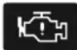
Thislampwillilluminateifanenginefaultoccurs thatwilleffectengineperformanceduringdriving.Please stopthecarassoonassafetypermits,switchtheengine OFFandcontactanMGAuthorisedRepairerimmediately.
EngineEmissionsMalfunctionWarning-Yellow
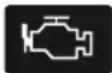
Ifanenginefaultoccursthatwilleffectengine performanceandemissionafterstartingthevehicle,this lampwillilluminate.PleasecontactanMGAuthorised Repairerassoonaspossible.
EngineCoolantT emperatureWarning-Red

Whentheenginecoolanttemperature warninglampilluminatesred, it indicates that the coolant temperature is high. If the engine coolant temperature continues to rise, the engine coolant temperature warning lamp will flash.
Highenginecoolanttemperaturecouldresultinsevere damage. Pleasestopthecarassoonassafetypermits, switchtheengineOFFandcontactanMGAuthorised Repairerimmediately.
LowOilPressureWarning-Red
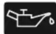
If this lamp illuminates after starting the vehicle, itindicate that the oil pressure is too low, which may result in severe engine damage. Please stop the car as soon as safety permits, switch the engine OFF and check oil level (referto "Engine Oil Level Check and Top Up" under the "Maintenance"). Contact an MGA authorised Repairer immediately.
AlternatorMalfunctionWarning-Red

thlismipluminateefestartirthe
vehicle, it indicates that the 12v battery charging system has a failure. Please contact an MGA authorised Repairer immediately.
INSTRUMENTSANDCONTROLS
Incasesoflowbatterypower,thepromptmessageswill appearintheinformationcentre.Inthiscase,thesystem willlimitorturnoffsomeelectricaldevices,pleasestart thevehicletochargethebattery.
Stop/StartIntelligentFuelSavingSystemStatus Indicator-Green

IftheStop/Startintelligentfuelsavingsystemis activated, thislampilluminatestoinformthedriverthat theengineiscontrolledbythesystem. Whenthesystem iscurrentlyunavailable, thislampflashestreetimesand thenextinguishes.
Stop/StartIntelligentFuelSavingSystem MalfunctionWarningLamp-Y ellow

IftheStop/Startintelligentfuelsavingsystem hasafailure, thislampilluminates. PleasecontactanMG AuthorisedRepairerassoonaspossible.
CruiseControlIndicator-Green/Yellow
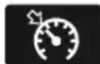
If the cruise control function is enabled, the systemwillenterintothestandbystateandtheindicator illuminatesinyellow.
Whenthecruise control system operates, this indicator illuminates green, indicating the cruise control system is activated.
Ifafailureinthecruisecontrolsystemisdetected, the indicatorwillflashinyellow.PleasecontactanMG AuthorisedRepairerassoonaspossible.
T yPressuMonitoringSystem(TPMS)
WarningLamp-Y ellow

If this lamiduminate indicates atyre pressureislow,pleasecheckthetyrepressures.
If this lamp flashes first and then remains after a period of time, it indicates the system has a failure. Please contact an MGA authorised Repairer at the earliest opportunity.
INSTRUMENTSANDCONTROLS
StabilityControl/T ractionControlSystem WarningLamp-Y ellow
If this lamp illuminates, it indicates that the stability control/traction control system has a failure. Please contact an MG Authorised Repairer immediately.
If this lamp flashes during driving, it indicates the system is operating to assist the driver.
StabilityControl/T ractionControlSystemOff WarningLamp-Y ellow
OFF Thislampwillilluminateifthedynamicstability control/tractioncontrolsystemismanuallyswitchedoff.
ABSMalfunctionWarningLamp-Y ellow

ThislampilluminatestoindicateanABSfault. IfanABSfailureoccurswhiledriving, ABSwillfunction
abnormally, butnormabrakingwillstillbeavailable. Please contactanMGAuthorisedRepairerassoonaspossible.
BrakeSystemMalfunctionIndicatorLampRed

If this lamp illuminates, it indicates a failure with
thebrakingsystemsuchasbrakefluidlossorelectronic brakeforcedistributionfailureReasestopthecaras soonassafetypermits,switchtheengineOFFandcheck brakefluidlevel(referto"BrakeFluidCheckandT opUp" underthe"Maintenance"section).Ifthebrakefluidlevel appearsatisfactorycontacarMGAuthorisedRepairerat theearliestopportunity.
Formanualparkingbrake, Helampilluminates when theparkingbrakeisappliedandextinguisheswhenitis fullyreleased. If theparkingbrakeisnotreleased, when thevehiclespeedexceeds3mph(5km/h), this warning lampwillflas If thelampremainsonaftertheparking brakehasbeenreleased, it indicate that there is a failure in thebrakingsystem. Leasestopthecarassoonas safetypermits, switch the engine OFF and contact an MG Authorised Repairer immediately.
INSTRUMENTSANDCONTROLS
ElectronicParkingBrake(EPB)/Automatic ParkingStatusIndicatorLamp-Red/Green

If this lamp illuminates red, it indicates the electronicparkingbrakeisenabledorintheprocessof dynamicbraking.Whenitflashesred,itindicatesthe electronicparkingbrakehasfailed.PleasecontacttheMG AuthorisedRepairerattheearliestopportunity.
Whentheautoholdsystemisoperatingtoassistthedriver, thislampilluminatesgreen.
ElectronicParkingBra(EPS)stem
MalfunctionIndicatorLamp-Yellow

Ifanelectronicparkingbrakesystemfailureis detectedorthesystemisunderdiagnosis, the indicator lampwillillumina. PleasecontactanMGAuthorised Repairerattheearliestopportunity.
HiDescenContr(HDC)n/Malfunction IndicatorLamp-Green/Y ellow
OperatingtheHDCswitchwillactivatethe systemwillenterthestandbymodeandthe pilluminatesgreen,thelampwillextinguish stemisturnedoff.Ifthevehicleisunderthe DCthegreenwarninglampwillflash.
If the HDC system detects safaultor fails, the warning lamp illuminates yellow. Please contact an MGA authorised Repairer immediately.
ElectPiowSteerSystem(EPS)/
ElectronicSteeringColumnLock(ESCL)
WarningLamp-Yellow/Red

Thewarninglampisusedtoindicateelectric
power assistesteeringfailureelectronsteering columnlockfailure.
Whenthislampilluminatesyellow,itindicatetheelectric powerassistedsteeringsystemhasageneralfailureand theperformanceisreduced.Pleasestopthecarassoonas safetypermits.Ifthelampstillilluminatesafterrestarting thevehicleanddrivingforashortwhile,pleasecontactan MGAuthorisedRepairerimmediately.
Whenthislampilluminatesred, itindicate that the EPShasafailurerelevant to the steering anglesensor. Please contact an MGA authorised Repairer at the earliest opportunity.
Whenthislampilluminatesredandflashes, itindicate the electricpowerassistedsteeringsystemhasaseverefailure and heavysteering. PleasecontactanMGAuthorised Repairerimmediately.
Whenthelampilluminatesyellowandflashes,itindicates theelectricsteeringcolumnlock * hasafailure.Pleasestop thecarassoonassafetypermits,switchtheengineOFF andcontactanMGAuthorisedRepairerimmediately.If thislampextinguishesafterflashingforawhile,itindicates thatthesteeringwheelislocked,pleaseattempttorotate thesteeringwheeltoremoveanyadverseloads.
LowFuelWarningLamp-Y ellow

Thewarninglampilluminatesyellowwhenthe
fuelremaininginthefueltankislow.lfpossible,please refuelbeforethelowfuelwarninglampilluminates.
Whenthefuellevelcontinuestofall, thislampflashes. When fuelisaddedtothetankandthefuellevelrises abovethealertlimit, thislampextinguishes. If it does not extinguish, pleasecontactanMGAuthorisedRepairerfor serviceassoonaspossible.
Note: Whendrivingonsteeporroughroadswhilethe fuellevelislow, the warninglamp may illuminate.
SystemFaultMessagesIndicator-Y ellow \*

Thisindicatorisusedtoalertthedrivertothe
factthatthereisawarningstoredinthevehicleIPKsystem. Pleasereferto"InformationCentre"inthissectionfor thesefailures.
INSTRUMENTSANDCONTROLS
ActiveSpeedLimitSystemWarningLamp—
Yellow
This warning lamp illuminates if an activespeed
limitsystemfailureisdetected.PleasecontactanMG AuthorisedRepairerassoonaspossible.
ActiveSpeedLimitSystemIndicator—Red

Whentheactivespeedlimitsystemisarmed oractive, if the target vehicles speed is currently set, this indicator illuminates and displays the target vehicles speed value.
When the activespeed limits system is working, if the currents speed exceeds these targets speed, this indicator will flash, and the system will immediately reduce the speed to below the targets speed. The activespeed limiter only uses engine braking to reduce speed - its not a substitute for physical brake application. If the vehicle need to be slowed or stopped quickly the brake pedal MUST be applied.
ParticulateFilterWarningLamp-Y ellow \*
Whentislampilluminatesyellow,itindicates
thattheparticulatefilterrequiresregeneration.Please drivethevehicleabove50mphuntilthelightisnolonger illuminated,andthennormalusagecanberesumed.
Note: During particulate filter regeneration the engine will run unevenly and at reduced power, this will cease after a successful regeneration.
Whenthislampflashes, itindicatesthattheparticulate filtrkingimealfunctiondicatdamp illuminatesatthesametirPleasecontactanMG AuthoriseRepairimmediatPleasethe warningignored, vehicleintreduced performancemodeandmaysubsequentlybeimmobilised.
Pleaserefeito "CatalyticConverterandParticulateFilter" in "Starting&Driving" section.
INSTRUMENTSANDCONTROLS
LightsandSwitches
MasterLightingSwitch
text_image
3 2 1 4IAUTOLamp
2SideLampsandSwitchIllumination
3DippedHeadlamps
4LightsOFF
AUTOLamp
WhentheSTART/STOPSwitchisintheACCposition,the autolightingsystemdefaultstotheONposition(1).The autolightingsystemwillautomaticallyswitchthesidelamps andswitchilluminationonandoffaccordingtotheintensity ofcurrentambientlight.
WiththeSTART/STOPSwitchswitchedtotheON position,theautolightingsystemdefaultstotheON position(1).Theautolightingsystemwillautomatically switchthesidelamps,switchilluminationanddipped headlampsonandoffaccordingtotheintensityofcurrent ambientlight.
Note: This function is realized by fitting a sensor capable of monitoring exterior lighting conditions in realtime your vehicle. The sensor is fitted in the centre of the fasci panel near the windscreen insomodels. DONOT mask cover this area, or headlamps may automatically go on when not necessary.
INSTRUMENTSANDCONTROLS
SidelampsandSwitchIllumination
T urnthemasterlightingswitchtoposition2tooperatethe sidelampsandswitchillumination.WiththeSTART/STOP SwitchintheOFFpositionifthelightingswitchisin position2andthedriver'sdooropenedaudiblewarning willsoundtoalertthedriver,thesidelampswillremain on.
DippedHeadlamps
When the START/STOP switch is in the ON position, turn them master lighting switch to position 3 to operate the dipped head lamps and sidelamps.
LightsOff
T urnthemasterlightingswitchtoposition4, this will switchoffalllamps, releasing the switch will allow it to return to the AUTO switch position.
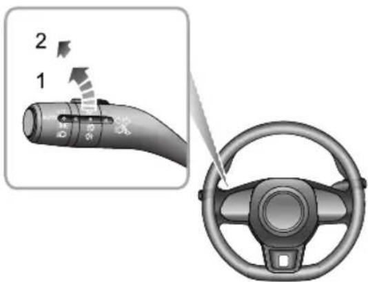
FollowMeHome
AftertheSTART/STOPSwitchisturnedoff, pull the lightingstalkswitchtowardsthesteeringwheel. This will enable the FollowMeHomefunction, dipped beam
headlampsandsidelampswillilluminatedependingupon thevehicleconfiguration.Itcanbesetinthe'Comfortand Convenience'intheVehicleSettingsontheentertainment display.
DaytimeRunningLamp
Thedaytimerunninglampsturnonautomaticallywhen theST ART/STOPSwitchisintheONposition.When thesidelampsareswitchedon,thedaytimerunninglamps extinguishautomatically.
FindMyCar
Afterthevehiclehasbeenleftinalockedconditionfora fewminutespressingthelockbuttonagainontheremote keywillenabletheFindMyCarfunction.Thisfunction willidentifythecarbymeansofanaudibleandvisualalert. PressingtheLockbuttononthehandsetagainwillsuspend thisoperationPressingtheUnlockbuttonwillcancel thisoperation.Thisfeaturecanbesetvia'Comfortand Convenience'intheVehicleSettingsontheentertainment display.
INSTRUMENTSANDCONTROLS
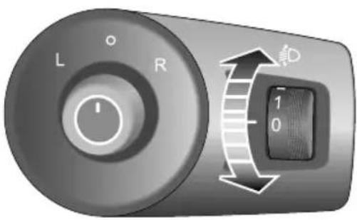
HeadlampLevellingManualAdjustment
text_image
L R 1 0Position0istheinitialpositionoftheheadlamplevelling adjustmentswitch. Theheadlamplevellingadjustmentcan bemadeasperthefollowingtableaccordingtothevehicle load.
| Location | Load |
| 0Driver,ordriver&frontpassenger. | |
| 1 | Alltheseatsoccupiedwithnoload. |
| 2 | Alltheseatsoccupiedplusanevenlydistributedloadintheboot,ordriverwithfullload. |
| 3 | Driveronly,plusanevenlydistributedloadintheboot. |
INSTRUMENTSANDCONTROLS
FogLampSwitch

Foglightsshouldonlybeusedwhenvisibility isbelow100m-otherroaduserscouldbe dazzledinclearconditions.
text_image
2 1FrontFogLamps \*
WiththeSTART/STOPSwitchintheONpositionandthe sidelampson,turnthefoglampswitchtoposition1,this
willturnonthefrontfoglamps. The indicator illuminates intheinstrumentpanelwhenthefrontfoglampsareon.
RearFogLamp
WiththeSTART/STOPSwitchintheONpositionandtheheadlampsorfrontfoglampson,turnthefoglampswitchtoposition2,thiswillturnontherearfoglamp,releasetheswitchtoallowittoreturntothelastposition.Theindicatorilluminatesintheinstrumentpanelwhentherearfoglampison.
INSTRUMENTSANDCONTROLS
DirectionIndicator/MainBeamSwitch

T akecarenottodazzleoncomingvehicles whendrivingusingmainbeamheadlamps.
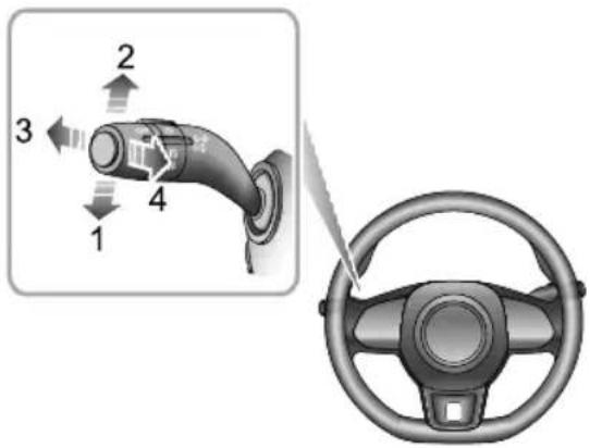
text_image
Diagram showing a car charger with four numbered components and a steering wheel view, illustrating the connection to the steering wheel.DirectionIndicators
MovetheleverdowntoindicateaLEFTturn(1).Movethe leveruptoindicateaRIGHTturn(2).Thecorresponding
GREENindicatorlampintheinstrumentpackwillflash whentheturningsignallampsareworking.
Rotating thesteeringwheelwillcanceltheindicator operation(smallmovementsofthesteeringwheelmay notoperatetheselfcancelling).T oindicatealanechange, movetheleverbrieflyandrelease,theindicatorswillflash threetimesandthencancel.
HeadlampHigh/LowBeamSwitching
WiththeSTART/STOPSwitchintheONpositionandthe masterlightingswitchturnedtoposition3,ortheauto functionhasswitchedthelightson,pushthelever(3) towardstheinstrumentpaneltoturnonheadlamphigh beams.Thehighbeamindicatorlampinstrumentpack illuminates,pressthelever(3)againtoswitchtoheadlamp lowbeams.
HighBeamFlash
T obrieflyflashthehighbeamonandoff, pullthelever towardsthesteeringwheel(4) and then release.
INSTRUMENTSANDCONTROLS
HazardWarningLamp
Pressthehazardwarninglampbuttontoturnon thehazardwarninglamps. Theturningsignallampsand directionindicatorlampswillflashtogether.Pressthe buttonagaintoswitchoffthehazardwarninglamps.All turningsignallampsanddirectionindicatorlampswillstop flashing.Formoredetailsandlocationreferto'Emergency Information"HazardWarningDevices'.
INSTRUMENTSANDCONTROLS
WipersandWashers
text_image
Diagram showing car steering wheel and valve mechanism with numbered directional arrows indicating motion or movement.WindscreenWiperOperation
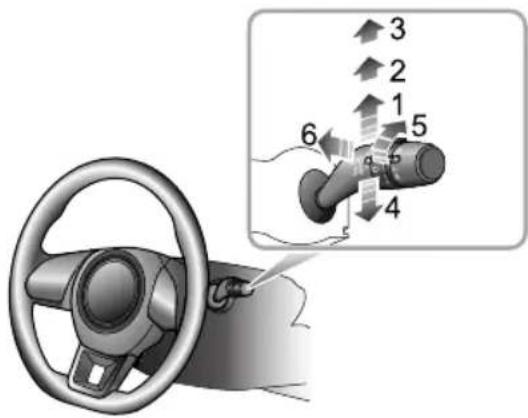
Thewipersandwasherswillonlyoperatewiththe START/STOPSwitchintheACC/ON/RUNNINGposition.
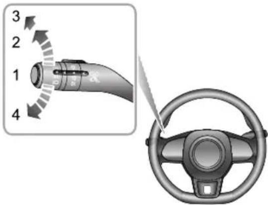
Operatethelevertoselectdifferentwipespeeds:
BypushingtheleveruptothelIntermittentwipeposition (1), thewiperswilloperateautomatically. T urntheswitch (5) * toadjusttheintermittentwipefrequency. Thisspeed will also changewith the vehiclespeed. Asthevehicle speed increases, thewiperfrequency increases. Asthe vehiclespeed decreases, thewiperfrequency decreases.
Somemodelsareequippedwitharainsensorfittedtothe interiorrearviewmirrorbasetodetectvaryingamounts ofwaterontheoutsideofthewindscreen.Withautomatic wipe,thevehiclewilladjustthewipingspeedaccordingto thesignalsprovidedbyrainsensor.T urntheswitch(5) toadjustthesensitivityofrainsensor.Asthesensitivity increases,thewipingintervaldecreases.
Note: Immediately operating the wiperonetime can be achieved by increasing the sensitivity of frainsensor.
INSTRUMENTSANDCONTROLS
Iftherainsensordetectsa continuous rainwater, the wiperwill keep working. Whennorain is detected, it is recommended to switch automatic wipe.
SlowWipe
Bypushingtheleveruptotheslowwipeposition(2), the wiperswilloperateslowly. Movethelevertore-select the wipespeed.
FastWipe
Bypushingtheleveruptothefastwipeposition(3), the wiperswilloperatefast.Movethelevertore-selectthe wipespeed.
SingleWipe
Pressingthelever(4)downandreleasingwilloperate asinglewipe,iftheleverishelldown,thewiperswill operateuntiltheleverisreleased.
Note: Whenthecarisstationary, if the bonnet is opened, the frontwiper/washer will stop work immediately.
IMPORTANT
Avoidoperatingthewiperonadrywindscreen.
Infreezingorextremelyhotweatherconditions, make the pixeladset
frozen/adheredtothewindscreen.
In winter, removes now or more from around the arms
andblades, including the wiped area of the screen.
ProgrammedWash/Wipe
Pullingthelevertowardthesteeringwheel(6)willoperate thewindscreenwashers. Afterashortdelay,thewipers willcommenceoperatinginconjunctionwiththewashers.
Not the wipers continue operating for further three wipes after the lever is released. After several seconds, there will be further wipet or remove any fluiddraining down the screen.
INSTRUMENTSANDCONTROLS
IMPORTANT
Ifthewashersfaltodeliverthescreenwashsolution (dirtoricemayhaveblockedthejets), releasethe leverimmediately. This will prevent the wipers from operating, and the consequent risk of visibility being impaired by dirtsmearing across the unwashed windscreen.
RearWindowWiperOperation
text_image
Diagram showing car steering wheel and directional arrows indicating motion or movement paths- Intermittentwipe(I)
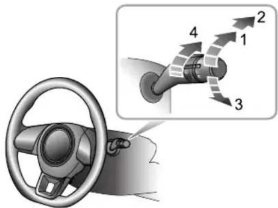
•Washandwipe(2)
•Washandwipe(3)
•Intermittentwipefrequencyadjustment(4)
Therearwindowwiperandwasherwillonlyoperate withtheSTART/STOPSwitchintheACC/ON/RUNNING positionandrewindowwiperwitdo intermittentwipe(1),therearwindowwiperwilloperate,
INSTRUMENTSANDCONTROLS
after3consecutivewipes,thewiperswillenterinto intermittentmode. Thetimeperiodbetweenthewipes canbeincreased/decreasedviatheintermittentwipe frequencyadjustmentswitch(4).
T urntherearwindowwiperswitchtowashandwipe(2) positionandhold,therearwindowwiperandwasherwill operate,therearwindowwiperwipesquickly releasethe switchallowingittoreturntointermittentwipe(1),the rearwindowwasherwillstopoperating,andthewiper wipesslowly,changethestalkswitchposition4toadjust thewipespeed.
T urntherearwindowwiperswitchtowashandwipe(3) andhold,therearwindowwiperandwasherwilloperate. releasetheswitchallowingittoreturntoOFFposition, therearwindowwasherwillstopoperating,andtherear windowwiperwipesfor3times,afterseveralseconds,the wiperwillwipeoncemoretoremovethewasherfluidon thewindscreen.
Note: Whenthetailgate is opened, rear windowwiper operations will be disabled.
Note: Whenthewindscreenwipersareswitchedon, if theshiftcontrolleverismovedto, orintheRposition, therearwindowwiperwilloperate.
INSTRUMENTSANDCONTROLS
SteeringSystem
AdjustmentofSteeringColumn

DONOTattempttoadjusttheangle of thesteeringcolumnwhilethevehicleisin motion. Thisisextremelydangerous.

natural_image
Diagram of a car steering wheel with a finger pointing to the steering wheel (no text or symbols present)T oadjusttheangleofthesteeringcolumntosuityour drivingposition:
I Fullyreleasethelockinglever.
2Holdthesteeringwheelinbothhandsandtiltthe steeringcolumnupordowntomovethewheelinto themostcomfortableposition.
3Onceaccomfortabledrivingpositionhasbeenselected, pullthelockingleverfullyuptolockthesteering columnintoitsnewposition.
INSTRUMENTSANDCONTROLS
ElectricPowerSteering

If the electric power steering fails or cannot operate the steering will appear very heavy, this will affect drivings safety.
Theelectricpowersteeringsystemonlyworkwhenthe vehicleisstarted. Thesystemoperatesviaamotorwith assistancelevelsautomaticallyadjustedbasedonvehicle speed,steeringwheeltorqueandsteeringwheelangle.
IMPORTANT
Holdingthesteeringwheelonfulllockforlongperiods willresultinareductioninpowerassistancecausinga heavierfeeltothesteeringforashortperiodoftime.
SteeringModeSwitching
Theelectricpowersteeringsystemprovides3different steeringmodes:
I Normal: provides moderate power assistance.
2Urban:providesahighlevelofassistance,withalight feel.
3Dynamic:provideslowlevelpowerassistance,witha heavierfeel.
Thesteeringmodeisselectableforvehiclespeedsupto60 mph(100km/h)throughthetouchscreeninterface.
Note: Steeringmodeselectionisonlyavailablewhen thesteeringwheelisnotbeingturned.Anychanges madeinthisstatewillnottakeeffectuntilthesteering wheelisstraightahead.
ElectricPowerSteering(EPS)WarningLamp
See "WarningLampsandIndicators" underthe
"InstrumentsandControls"section.
INSTRUMENTSANDCONTROLS
Horn
natural_image
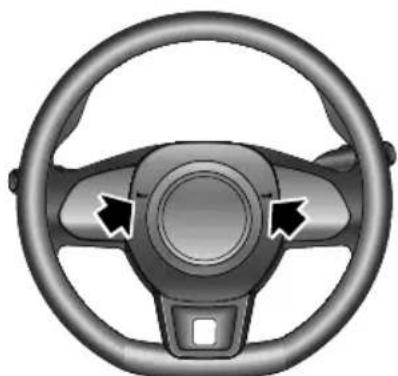
Top-down view of a car steering wheel with three blades and a central hub (no text or symbols)avoid any potential conflict with the operation of the airbag.
IMPORTANT
T oavoidpossibleSRSissues, pleasedonotpresswith excessiveforceorhittheairbagcoverwhenoperating thehorn.
Pressthehornbuttonareaonthesteeringwheel(as indicatedbythearrow)tooperatethehorn.
Note: The vehicle horn switch location and the driver's air bag are located in close proximity on the steering wheel. The illustrations show the position of the horn switches, please ensure that you press in this are a
INSTRUMENTSANDCONTROLS
Mirrors
DoorMirrors
Note: Objectsviewedindoormirrorsmayappear furtherawaythantheyactuallyare.
ElectricDoorMirrorGlassAdjustment
text_image
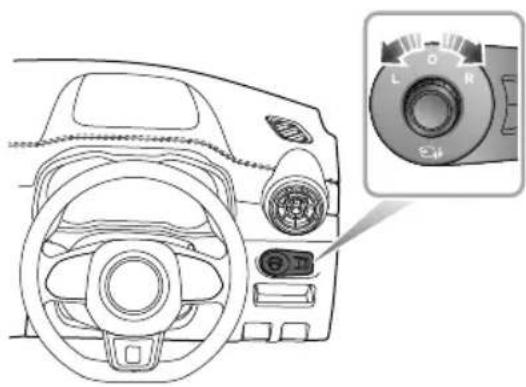
Diagram of a car dashboard with labeled rotary knob and control panel, showing front and side views- Themirroradjustmentfunctionwillworkwiththe powersysteminallmodes,includingOFF ,ACCand ON/RUNNING.
- Rotatetheknobtoselectleft(L)orright(R)rearview mirror.
- Movetheknobinthedesireddirectiontoadjustthe angleoftheexteriormirrorglass.
- Upon completion of the adjustment, rotatetheknob back to the central position, this will ensure no accidental adjustment of the mirror.
HeatingElements \*
Thedoormirrorshaveintegralheatingelementswhich disperseiceormistfromtheglass.Theheatingelements operatewhiletheHeatedRearWindow isswitchedon.
Note: The heating element so frear window and mirror will only work when the powersystem is running.
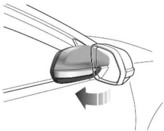
MirrorFolding
Themirrorscanbefoldedbacktowardsthesidewindows intoa'park'positiontoenablethecartonegotiatenarrow openingsandavoidcollisions.
INSTRUMENTSANDCONTROLS
natural_image
Diagram of a car frontview mirror showing the blade and side mirror (no text or symbols)ManualFoldingofDoorMirror
Forvehiclesnotfittedwiththeelectricdoormirrorfold option,theexteriormirrorscanonlybefoldedbackwards manually.
ElectricFoldingofDoorMirror
Forvehiclesfittedwithelectricdoormirrorfolding,rotate theknobtothemiddleposition,andpushtheknobdown.
Thedoormirrorswillbefoldedautomatically.Pushing theknobdownwardsagainwillreturnthemirrorstotheir originalposition.
Operatingthekeyfoblock/unlockbuttonswillfold/unfold thedoormirrors.
Note: Electrical folding doormirrorsthath have been moved from their positions by manual or accidental means must be reset by operating the knob to complete fold and deployment on time.
IMPORTANT
- Doormirroglassadjustmentsanddoormirror foldingareoperatedbyelectricalmotors.Operating themdirectlybyhandmaydamagetheinternal components.
- Washingorflushingdoormirrorswithhighpressure waterjetsorcarwashesmayresultinelectrical motorfailure.
INSTRUMENTSANDCONTROLS
InteriorRearviewMirror
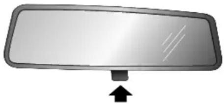
Adjustthebodyoftheinteriorrearviewmirrortoachieve thebestpossibleview.Theanti-dazzlefunctionofthe interiorrearviewmirrorhelpstoreduceglarefromthe headlampsoffollowingvehiclesatnight.
ManualAnti-dazzleInteriorRearviewMirror
natural_image
Simple diagram of a rectangular mirror with an arrow pointing upward (no text or symbols)Movetheleveratthebaseofthemirrorforwardto'dip' themirrorandachievetheanti-dazzlefunction.Normal visibilityisrestoredbypullingtheleverbackagain.
Note: In some circumstances, the view reflected in 'dipped' manual mirror can confuseth driver as to the precis elocation off following vehicles.
INSTRUMENTSANDCONTROLS
Sunvisor

Thevanitymirroronthedriversideshould onlybeusedwhenthecarisstationary.
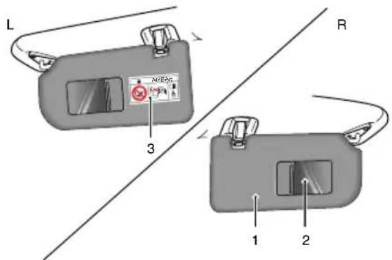
Sunvisors(1)arearrangedontheroofaheadofboththe driverandthefrontpassenger.Somemodelshavevanity mirror(2),dependingonthevehicleconfiguration.For themodelswhichhavevanitymirror,pullthesunvisor downwardandslidethecoverasidetousethevanity mirror.
Note:Warningsandinstructionsonuseofchild restrain(b)attachedto thefe passengersunvisor.
NEVERuse rearward facing child restraint some at protected by an ACTIVE AIRBA Gr from of the DEATH or SERIOUS INJURY to the CHILD can occur. Refer to 'Disabling the Passenger Airbag'.
text_image
L 3 R 1 2INSTRUMENTSANDCONTROLS
Windows
PowerOperatedWindowSwitch
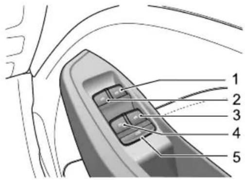
text_image
Technical diagram of a car interior with numbered parts labeled 1 to 5FrontRightWindowSwitch
2FrontLeftWindowSwitch
3RearRightWindowSwitch
4RearLeftWindowSwitch
5 RearWindowIsolationSwitch
WindowOperation

Ensurechildrenarekeptclearwhenraisingor loweringawindow.

Improperuseoractivationoftheelectric windowsbychildrencouldcauseseriousharm orevendeath.Itistheresponsibilityofthe driverandadultpassengerstoensurethat whencarryingchildrenthenecessarysteps aretakentoisolatethewindowoperation. Thisshouldincludetheremovalofthekey whenchildrenareleftaloneinthevehicle.
Pushtheswitch(1-4)downtolower, andpulltheswitchuptoraisethewindow. Thewindowwillstopmovingassoon astheswitchisreleased(unlessthe'One-T ouch'function isactive).
Note: The front and rear passenger windows can also be operated by individual window switches, mounted oneachdoor. Therear window switches will not be operated if therear windowisolations switch has been activated.
INSTRUMENTSANDCONTROLS
Note: The electric window can be operated with the vehicle powersystem in the ACC, ON and RUNNING positions. (Forsafety: door should be closed).
RearWindowIsolationSwitch
Pressthebutton(5)toisolatetherearwindowcontrols, pressagaintorestorecontrol.
Note: It is recommended that you ISOLATE therear windows switches when carrying a child.
"One-T ouch"Down
Thedriver'swindowcontrolswitch(1)has2positions. Shortpresthewindowcontrolswitchtothe"2"position andrelease. Thewindowautomaticallydescendstofully open. Windowmovementcanbestoppedatdesired positionatanytimebybrieflyoperatingtheswitchagain.
"OneT ouch" Upwith "Anti-Trap"\*
Thedriver'swindowcontrolswitch(1)hasthe "one-touch"upfunction.Liftingtheswitchtothe"2" positionforashorttimeandreleasingwillautomatically
closethewindowcompletely.Windowmovementcan bestoppedatadesiredpositionatanytimebybriefly operatingtheswitchagain.
The "Anti-Trap" functionisasafetyfeaturewhichprevents thewindowfromfullyclosingifanobstructionissensed-ifthishappensthewindowwillopenslightlytoallowthe obstructiontoberemoved.
Note: DONOToperatethepowerwindowcontrols continuouslyseveraltimesinashorttimeframe, otherwisethepowerwindowcontrolsmaybedisabled toprotectthemotor. If this occurs, please wait a few seconds until the motor cools down the case of the driver's window with "One T ouchand Anti-T rap" please wait 30 seconds prior to operation some cases it may take 30 minutes to completely cooldown, during which timethenegative battery lead should not be disconnected.
Note: If the battery is disconnected, the "One-Touch" and "Anti-Trap" features will belost. Torestore this feature, fully open and then fully closet the window holding the switch for 5 seconds in the closed position.
INSTRUMENTSANDCONTROLS
Sunroof \*
Thesunroofconsistsoftwoglasspanels,onlythefront sectioncanbeopenedbyslidingortilting.Thesunshade canbeopenedorclosedasacompleteunit.
Instructions

DONOTallowpassengerstoleanoutofan opensunroofwhilstthevehicleisinmotion. Injuriesmayoccurfromobjectssuchastree branches.

Safetyofthevehicleoccupantsmustbe observedatalltimes.DONOTallowlimbsto beplacedinthemovingpathofthesunroof atanytime,injurymayoccur.
- Avoidfully opening the sunroof during grain showers.
- Itisadvisednottoopenthesunroofathighspeeds.
-
Wherepossible, pleasecleanoffanyresidualwateror raindropsoffthesunroofpriortoopening.Failureto dosomayresultinwaterenteringthecar.
-
DONOTuseabrasivematerialstocleanthesunroof glass.Useonlyproprietyglasscleaneroralcoholbased solvent.
- DONOTholdtheoperatingswitchintheopen/close positionforanylengthoftimeafteroperationis complete,thiscoulddamagetheelectricalcomponents.
- Cleanthesunroofregularlytomaintainoperationand performance. VisitanMGAuthorisedRepairerfor serviceasrequired.
INSTRUMENTSANDCONTROLS
SunroofOperation
Thesunroofwilloperatewhenthevehiclepowersystem isintheACCorON/RUNNINGmodes.
SunroofGlassOperation
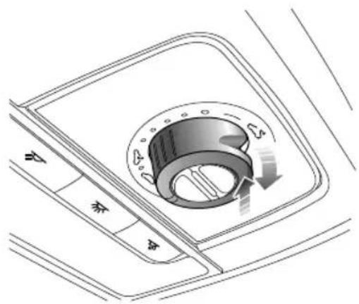
text_image
Diagram of a car air conditioner unit with labeled controls and airflow direction arrowsOpeningtheSunroofGlassusingTilt
With the sunroof glass fully closed, presstherear part of the switch in the direction of the arrow was indicated in the graphically tilt the glass to the open position. Operation can be interrupted at the desired point by pressing the switch again.
ClosingtheSunroofGlassfromTilt
Pulldowntherearoftheswitchtoautomaticallyclosethe sunroofinthedirectionasindicatedbythearrow.Briefly pulldownontheswitchagainwillinterrupttheoperation atthedesiredposition.
T omanuallyclosethesunroof,pulldowntherearofthe switchinthedirectionasindicatedbythearrowandhold, untilthesunroofreachesthedesiredposition.
OpeningtheSunroofGlassbySliding
Rotatetheswitchcompletelyclockwiseand
holduntilthesunroofslidesfullyopen.T opartiallyopen thesunroof, placetheswitchintherequiredrangeposition.
INSTRUMENTSANDCONTROLS
ClosingtheSunroofGlassbySliding
Rotatetheswitchcompletely
counterclockwise,thesunroofwillslidefullyclosed.T o partiallyclosethesunroof,placetheswitchintherequired rangeposition.
SunroofSunshadeOperation
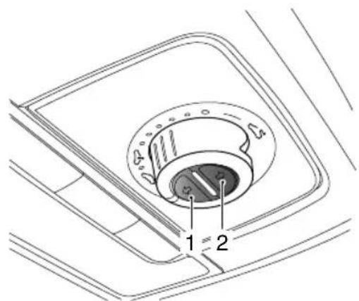
text_image
1 2Openingthesunshade.
Shortpressthebutton(2)toautomaticallyopenthe sunshadetoitsfullextent.Shortpressthebuttonatany timetocanceltherequestandstopthesunshadeatthat position.
T omanuallyopenthesunshade,pressandholdthebutton untilthesunshadereachesthedesiredposition,then releaseit.
ClosingtheSunshade
Shortpressthebutton(1)toautomaticallyclosethe sunshadecompletely.Shortpressthebuttonatanytimeto canceltherequestandstopthesunshadeatthatposition.
T omanuallyclosethesunshade,pressandholdthebutton untilthesunshadereachesthedesiredposition,andrelease it.
Note: If the vehicle is to be parked directly sunlight for length of time it is recommended that the sunshade be closed to protect the interior trim components from damage, and to help regulate the in-cartemperatures.
INSTRUMENTSANDCONTROLS
Anti-pinchFunction
Thesunroofandsunshadefeaturean“Anti-Pinch” function, thisisasafetyfeaturewhichpreventsthe sunrooforsunshadefromfullyclosingwhilstinthe automaticmodeifanobstructionissensed-ifthis happensthesunroof/sunshadewillopenslightlytoallow theobstructiontoberemoved.
ForciblyClosingtheSunroof(over-ridingtheanti pinch)
T oforctibyclosethesunroofglassafterananti-pinch intervention, gently pull therearoftheswitchdownwards within 5 seconds and hold in position until the sunroof glass is fully closed.
Note: The antipinch function is suspended during this operation.
ForciblyClosingtheSunshade(over-ridingtheanti pinch)
T oforctibyclosethesunshadeafterananti-pinch intervention, presstheclosebuttonwithin5secondsand holdituntilthesunshadeisfullyclosed.
Note: The antipinch function is suspended during this operation.
Note: The anti-pinch function only works when closing the sunroof during the slide operation.
SunroofInitialisation
Intheeventofapowerfailureorbatterydisconnection whenthesunroofglassorsunshadeisinmotion,the sunroof/sunshadewillrequireinitialisationwhenthepower isrestored.
T ocarryoutthesunroofglassinitialisationoperation: Fullyclosetheglass-gentlypulltherearoftheswitch downwardandholdinpositionfor10seconds,thesunroof wilopenapresetamountandstop,itwillthenclose automatically-thesunroofglassistheninitialised.During thewholeprocess,theswitchmustremaininthepulled downposition.
INSTRUMENTSANDCONTROLS
T ocarryoutthesunshadeinitialisationoperation:
Fullyclosethesunshade-pressthecloseswitchandhold inpositionfor 10seconds,thesunshadewillopenapreset amountandstop,itwillthencloseautomatically-the sunshadeistheninitialised.Duringthewholeprocess,theswitchmustremainpressed.
INSTRUMENTSANDCONTROLS
InteriorLights
text_image
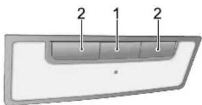
2 1 2Pressanyoneofbuttons(2)toswitchonthe correspondinglamp,andpressitagaintoswitchthelamp off.
AutomaticOperation
Presstheinteriorlightsswitchbutton(1)toturnon automaticoperation,andpressitagaintoturnoffthe function.
Interiorlightilluminationoccursautomaticallywhenever thefollowingoccur.
•Thecarisunlocked.
• Anydoororthetailgateisopened.
•Thevehiclepowersystemisswitchedoff,providingthe sidelightshavebeenilluminatedduringtheprevious30 seconds.
Note: If a door or the tail gate is open for more than 15 minutes, the front interior lamp will be switched off automatically to avoid battery drain.
INSTRUMENTSANDCONTROLS
PowerSocket

Pleaseensurethesocketblankingplugis insertedwhenthepowersocketisnotinuse. Thiswillensurenodebrisorforeignobjects enterthesocketpreventingitsuseorcause shortcircuits.

The 12Vpowersockethasavoltagerating of 12V, and themaximumpower of 120Watt, please DONOTuseanyelectrical appliance that exceeds this rating.

Extendeduseoftheaccessorypowersocket andUSBsocketwhentheengineisswitched offwillcauseprematuredischargingofthe vehiclebattery.
text_image
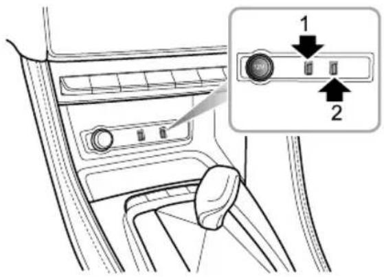
Diagram of car interior showing dashboard and control panel with labeled buttons 1 and 2The 12Vpowersocketislocatedundertheshiftcontrol knobassemblyinthecentreconsole.Itcanbeusedas apowersupplywhentheSTART/STOPSwitchisinthe ACCorON/RUNNINGpositionswhentheblankingplug isremoved.
LocatedtotherightofthepowersocketaretwoUSB ports. Bothofthemcanbeusedtoprovidea5Vpower supplyoradatatransmissionconnection.
INSTRUMENTSANDCONTROLS
Note: The vehicle is not supplied with a cigar lighter. If required please contact your local MGA authorised Repairer.
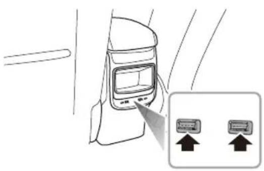
TherearetwoUSBportslocatedattherearofthecentre console,theseprovide5Vvoltagewhenservingasthe poweroutlet.
Note: Duetodifferencesinconfigurationthecharging functionoftheUSBportwillbeslower.
natural_image
Diagram of a car interior showing a touchscreen device and two labeled arrows pointing to it (no text or symbols present)ThereisalsooneUSBportlocatedintherearviewmirror mountingtrimcover,thisprovidesa5Vpowersource.
INSTRUMENTSANDCONTROLS
StorageDevices
Instructions
- Please close all storage devices when the vehicle is in motion. Leaving these storage devices open may cause personal injury in cases of sudden start-off, emergency braking and car accident.
- Donotplaceflammablematerialssuchasliquidor lightersinanystoragedevices. Theheatinhot conditionsmayigniteflammablematerialsandleadto afire.
GloveBox
natural_image
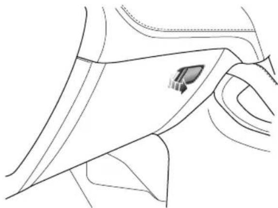
Pure technical line drawing of a mechanical component or part without any text, numbers, or symbolsT oopentheglovebox, pullthehandleontheglovebox cover(asindicatedbythearrow).
Pushtheboxcoverforwardtoclosetheglovebox.Make surethegloveboxisfullyclosedwhenthevehicleisin motion.
INSTRUMENTSANDCONTROLS
CardBox
natural_image
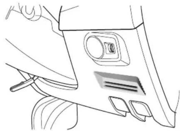
Line drawing of a car interior panel with handle, seat, and camera (no text or symbols)Locatedinthedriversidelowerdashtrimpanel.
CentreConsoleArmrestBox
natural_image
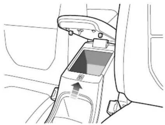
Interior view of a car showing the rearview seat and dashboard (no text or symbols visible)Liftthearmrest(arrowed)toopenthecompartmentcover. Putthecoverdowntocloseit.
INSTRUMENTSANDCONTROLS
Loadspace

DONOTplacearticlesontherearparcel shelf,theycouldmovecausingpersonal injuryintheeventofanaccident emergencybrakingorhardacceleration.
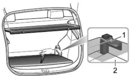
Thesparewheel/tyrerepairkitandtoolkitarestowed beneaththeloadspacecarpet,liftthecarpetforaccess. Alwaysrefitthecarpetafteruse.
Inaddition, Theloadspacecarpetheightcanbeadjusted by usingthecarpetbracket(figure 1,2).
natural_image
Diagram of a car interior showing a rearview seat, a close-up view of the side panel, and a 3D model of a rectangular object (no text or symbols present)Therearparcelshelfisconnectedtothetailgateusing strapsandhooks.Whenopeningthetailgate,theshelfwill automaticallyberaised.
INSTRUMENTSANDCONTROLS
CupHolder

Donotplacehotdrinksinthecupholder whilstdriving.Spillagemayresultinpersonal injuryordamage.
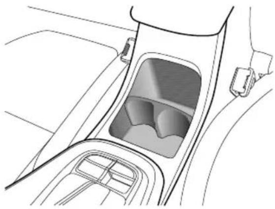
CentreConsoleCupHolder(EPB)
natural_image
Line drawing of a car interior showing the dashboard and seat area (no text or symbols)Thecentreconsolecupholderissituatedatthefrontend of thecentreconsolearmrestassembly.
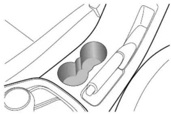
CentreConsoleCupHolder(IPB)
natural_image
Diagram of a car interior showing a vehicle and its internal components (no text or labels)Thecentreconsolecupholderissituatedatthefrontend of thecentreconsolearmrestassembly.
INSTRUMENTSANDCONTROLS
RoofLuggageRack \*

RoofloadsMUSTNOTexceedthemaximum authorisedload. Thismayleadtoinjuryor vehicledamage.

Looseorimproperlyfixedloadsmayfallfrom theroofluggagerackandleadtoanaccident orcausepeopleinjury.

When heavy or large items are carried on the offluggagerackit may lead to changes in steering, handling and braking characteristics. Please avoid sharp manoeuvres, heavy braking and excessive acceleration.
Payattentiontothefollowinginusingtheroofluggagerack:
Secureloadstowardthefrontoftheroofasfaras possible.distributeloadsevenly.
DONOTuseautomaticcarwasheswithloadsonthe roofluggageack.
The overall height of the car is different when loads are fitted to other of fluggagerack. Please ensure there is adequate clearance when entering tunnel and garages.
Ensure the loadscarried by the roof gagerack do not impedeoperation of the sunroof, roof antenna of tailgate opening.
When installing or removing a piece of loading equipment, follow instruction provides the manufacture of loading equipment.
MaximumAuthorisedLoadfortheRoof
Themaximumauthorisedloadfortheroofis75kg, this includestheweightoftheroofloadsandthatoftheloading equipmentinstalled.
Ensure you are aware of the weight of loads, and weigh them when necessary. Never exceed the maximum authorised load or the roof.
PeriodicalCheck
Always checked conditional connectors and fastening before Periodically shecht bolt connectors and fastening for security.
AirConditioningandAudio Systems
70Ventilation
73ElectronicTemperatureControl
79 EntertainmentPlayer
AIRCONDITIONINGANDAUDIOSYSTEMS
Ventilation
text_image
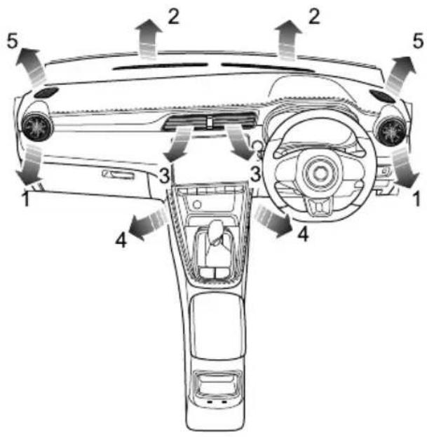
Diagram of a car interior with numbered components and directional arrows indicating airflow or movement.I SideVents
2Windscreen/DefrostVents
3CentreVent
4FrontFootwellV ents
5FrontSideWindowV ents
AIRCONDITIONINGANDAUDIOSYSTEMS
Theheating,ventilationandairconditioning * system providesfresh,cooling * orheatedairtotheinteriorof thecar.Freshairisdrawninthroughtheairintakegrille underthefrontwindscreenandtheairconditioningfilter.
Alwayskeeptheairintakegrilleclearofobstructionssuch asleaves,snoworice.
A/CParticle/PollenFilter
Theparticle/pollenfilterhelpstokeepthecarinteriorfree frompollenanddust. T oremainfullyeffective, thefilter shouldbereplacedattherecommendedserviceinterval.
Vents
CentreVents

natural_image
Diagram of a car interior showing airflow or traffic flow between two vehicle sections (no text or symbols)Slidethebuttoninthecentreofthelouvrescompletely totheletorrighttoopenorclosethevent,adjustthis buttontodirecttheflowofair.
T ogglethebuttonatthecentreofeachventupanddown, leftandrighttoregulatetheairdirection.
AIRCONDITIONINGANDAUDIOSYSTEMS
SideVents
natural_image
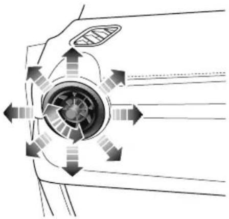
Diagram of airflow or wind patterns around a central circular component, with directional arrows indicating movement (no text or symbols)Rotatethecentrethumb-wheelclockwiseor anti-clockwisetoopenorclosethevent. T ogglethe centrethumb-wheelup, down, leftor rightto adjust the air direction.
AIRCONDITIONINGANDAUDIOSYSTEMS
ElectronicT emperatureControl
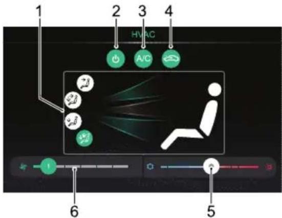
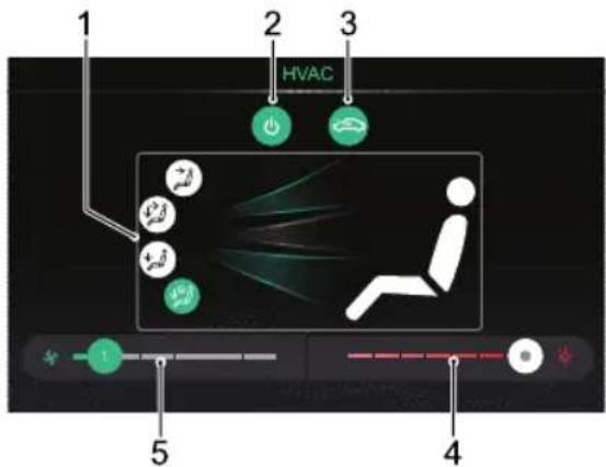
InfotainmentScreenControlInterface
WithA/CCooling
WithoutA/CCooling *
text_image
1 2 3 4 HVAC A/C 6 5IAirDistributionMode
2SystemOn/Off
3A/CCoolingOn/Off
4AirRecirculationMode
5T emperatureControl
6BlowerSpeedControl
text_image
HVAC 1 2 3 5 4IAirDistributionMode
2SystemOn/Off
3AirRecirculationMode
4T emperatureControl
5BlowerSpeedControl
AIRCONDITIONINGANDAUDIOSYSTEMS
SystemOn/Off
T ouchtheSystemOn/OffButtononthecontrolinterface toswitchthesystemon,allfunctionswillreverttothe statebeforeshutdown.T ouchagaintoswitchoff.
Note: Turningofftheinfotainmentscreenwillnot affecttheoperationofthesystem
A/CCoolingOn/Off \*
T ouchtheA/CCoolingOn/OffT ouchButtontoturnthe A/CcoolingfunctionON/OFF.
Note:
I Thecooling/heatingmodeoftheairconditioning willonlyoperatewhentheengineisrunning.
2Theheating/ventilationfunctionisstillavailable, whentheA/Ccoolingisswitchedoff.
3A smallamountofwatermayremaininthe airconditionerafterusage, this may produce a peculiarsmell. If this is a particular issue, it is recommended to switch the cooling function
andruntheblowerforawhilewiththeengine runningpriortoswitchingoff.
AirRecirculationMode
Touchtherecirculationbuttononthecontrolinterfaceto operatetheairrecirculationfunction,theimagedisplayed intheswitchwillchangetodisplayyourchosenposition (externalorinternalcirculation),iftheairintakeisclosed theairinsidethecarisrecirculated,preventingtheentry oftrafficfumes.
Recirculationmodeisautomaticallyactivatedwhenthe screenwashersareusedorreversing.
Note:Leavingthesysteminrecirculationmodecan causethewindscreentomist. If this happens, switch offrecirculation and turn the control maximum demisting.
AirDistributionMode
Select the corresponding Air Distribution Mode Touch Button as required to regulate the air distribution mode.
AIRCONDITIONINGANDAUDIOSYSTEMS
| T ouch Button | IconsonInterface | AirDistribution Mode |
 |  | T o‘face’ |
 |  | T o‘face’and‘feet’ |
 |  | T o‘feet’ |
 |  | T o‘feet’+‘windscreen’ |
T o'face'.Directsairtotheside,centreandcentreconsole vents.
T o'face'and'feet'.Directsairtothefootwell,side,centre andcentreconsolevents.
T o'feet'.Directsairtothefootwellvents.
Note: In this mode, as small amount of airflow will be directed to the beside, front sidewindow and windscreen/defrost Vents.
T o'feet'+'windscreen'.Directsairtothefootwell, windscreen/defrostandfrontsidewindowvents.
Note: In this mode, asmall amount of airflow will be directed to the beside events.
BlowerSpeedControl
Slidetheblowerspeedsegmentsleftorrighttoregulate theblowerspeed,thelowestpositionis1.
Touchblowerspeedsegmentquicklythe requiredblowerspeed.
T emperatureControl
Slidethetemperaturesegmentleftorrighttoregulate the temperatureoftheairsuppliedbythevents.
Touch the temperature segment to quickly set there required temperature.
AIRCONDITIONINGANDAUDIOSYSTEMS
ControlPanel
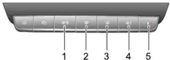
text_image
1 2 3 4 5IA/CControlShortcut
2Defrost/DemistButton
3HeatedRearWindowButton
4BlowerSpeedControlButton
5T emperatureControlButton
A/CControlShortcut

ShortpresstheA/Ccontrolshortcuttodisplay itioninginterfaceontheinfotainmentscreen.
LongpresstheA/Ccontrolshortcuttoswitchthesystem on, allfunctionswillreverttothestatebeforeshutdown. Longpressagaintoswitchoff.
BlowerSpeedControlButton

Presstheblowerspeedcontrolbuttonupward rdtoregulatetheblowerspeed.
T emperatureControlButton

Pressthetemperaturecontrolbuttonupward rdtoregulatethetemperatureoftheair thevents.
AIRCONDITIONINGANDAUDIOSYSTEMS
Defrost/Demist

PressDefrost/DemistButtononthecontrol panel, the indicator son the button and display illuminate, the A/C cooling and external circulation functions are switched on, and the system enter sthemost effective warm or cold air setting to clear the windshield and side window.
PressingtheDefrost/DemistButtonorthetouchbutton onthedisplayagainwillexitthedefrost/demiststate, theindicatorgoesout,andthesystemwillreturntothe previousstate.
Inthedefrost/demistmode, operationoftheA/Ccooling on/offbuttonwillswitchthecompressoronoroff; operationoftheaircirculationmodebuttonwillswitch betweeninternalcirculationandexternalcirculation, withoutaffectingthedefrost/demistmodeineithercase; operationofotherairdistributionmodeswillswitch toacorrespondingairdistributionmodeandquitthe defrost/demistmode.
Note: Whenthedefrost/demistfunctionisswitched onbelowapresettemperature,theheatedrear windowfunctionwillautomaticallyoperate,the Defrost/Demistbuttonandtheheatedrearwindow buttonindicatorlightswillilluminatesimultaneously.
HeatedRearWindow

Theheatingelementsontheinsideoftherear windowareeasilydamaged.DONOTscrape orscratchtheinsideoftheglass.DONOT sticklabelsovertheheatingelements.
Pressthisbuttononthecontrolpanelto operatetheheatedrearwindowfunction,theindicator intheswitchwillilluminate.Theheatedrearwindow functionwillautomaticallyturnoffafteroperatingfor15 minutes.Iftheswitchispressedagainwithin5minutes, theheatedrearwindowwilloperateandthenremainon forafurther8minutesBressingtheswitchwhilstthe heatedrearwindowisonwillswitchoffthefunctionand extinguishtheindicatorintheswitch.
AIRCONDITIONINGANDAUDIOSYSTEMS
Note: The heated rear window will only operate when the engine is running.
Note: Heateddoormirrorsonlyoperatewhenthe heatedrearwindowisactivated.
•Inalcirculation
•Extralcirculation
A/CDisplay
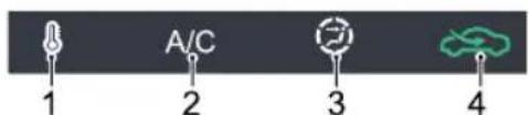
text_image
A/C 1 2 3 4ITemperatureStatus
2A/CCoolingStatus
3BlowerSpeed/AirDistributionModeStatus :
•Forface'
•For face'and'feet'
•For feet'
• For'feet'and'windscreen'
•For'windscreen'
4AirRecirculationModeStatus :
AIRCONDITIONINGANDAUDIOSYSTEMS
EntertainmentPlayer
ImportantSafetyInformation
- Donotattempttofit, repairormodify the entertainmentsystembyyourself, because there are high-voltage components in the device, which may cause electric shock. For internal inspection, adjustmentorrepair, please consult a local MG Authorised Repairer.
- Donotallowthisentertainmentandnavigation systemoomintcontactwithliquidquids oforeigobjectenteintohientertainmentand navigationsystempleasparkouvehiclateafe placimmediatelyswitchofftheignitionandcontact alocalMGAuthorisedRepairDonotusethe entertainmentandnavigationsysteminthiscondition because doing may resultfireelectrishockor otherfailure.
• If you notice smoke, abnormal noises prodours from the entertainment system any other abnormalities on the screen, switch the ignition off immediately and contadocally. Authorise Repairs service.
Using this entertainment system in this condition may result in permanent damage to the system.
- Operationofthenavigationorvideofunctionsofthesystemprohibitedvilstheehiclémotion.
MGMotorUKacceptsnoresponsibilityforany consequencesaused byioperationPleaspark yourvehicleinasafelocationselectPark/Neutral,and applytheparkingrakebeforemakingthenecessary adjustmentsorwatching"Video".
•Particularly high or particularly low temperatures will interfere with normal operation. If the vehicle is not used, park directors in cold location for long time, may become particularly hot cold, in this environment the system may not work properly. Once the temperature inside the back normal, the system will resumenormal function if it does not resume please contact a MAuthorised Repaire for assistance. - Switchoffentertainmentandnavigationsystemduring refuelling.
AIRCONDITIONINGANDAUDIOSYSTEMS
- Excessiveuseoftheentertainmentandnavigation systemwithoutthevehiclebeingdrivenorengine runningcandrainthevehiclelowvoltagebattery.
- When using a mobile phone, keep the antenna of the mobile phone away from the screentoprevent the disruption of videosign in the form of spots, colored stripes, etc. on the screen.
CautionsforUsingScreen
- T oprotectthescreenagainstdamage, alwaystouch panelkeyswithyourfinger. Atouchpenmaybeused for special calibration.
- Please take care to protect the screen again at direct sunlight. Extended exposure to direct sunlight will result in screen malfunction due to high temperature.
- Whentetemperatureisbeyondtheoperating temperaturerange(-30°Cto+85°C), pleasedonot usethescreen, because the screen may not operate normally and could be damaged.
- Donotuseexcessiveforcetodraganddroporpress thescreen,damageorscratchingmayoccur .
•T oremovedustfromthescreenorcleanthescreen, poweroffthesystemfirst,thenwipethescreenwitha drysoftcloth.Whenwipingthescreen,takecarenot toscratchthesurface.Donotuseirritativeorabrasive chemicalcleaners.
AdditionalNotes
- Sometypesofexternalstoragedevicesmaynotbe recognised. This may result in the files not being played or displayed normally.
- Becauseoffilecharacteristics, fileformat, recorded application, playbackenvironment, storageconditions and other factors, it may not be possible to play the files normally.
AIRCONDITIONINGANDAUDIOSYSTEMS
BasicOperations
ControlPanel
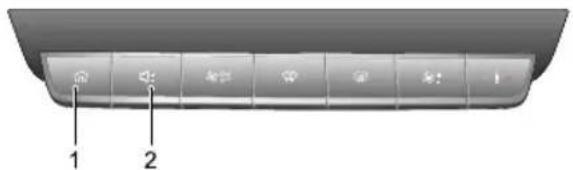
text_image
Diagram of a vehicle rear panel with labeled buttons and indicatorsI(HOME)Button
Shortpresstoreturntothemaininterface.
2VolumeAdjustingButton
MainSystemInterface
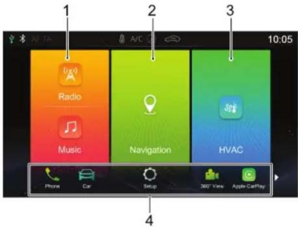
text_image
1 2 3 10:05 Radio Music Navigation HVAC Phone Car Setup 360° View Apple CarPlayIRadio/Music
TouchtoentertheRadio/Musicinterface.
2Navigation
TouchtoentertheNavigationinterface.
3HVAC
AIRCONDITIONINGANDAUDIOSYSTEMS
TouchtoentertheACinterface.
4Others
Touchers paleftorrightatthebottomof thescreenetoviewthefollowingfunctions.
•Phone
Touch toentertheBluetoothPhoneinterface.
Car
TouchtoentertheV vehicleSettingsinterface.
- Setup
Touch toentertheSettingsinterface.
•360View
Touch toenterthe360Viewinterface.
-AppleCarPlay
TouchtoentertheAppleCarPlayinterface.
-AndroidAuto
TouchoentertheAndroidAutointerface.
•Pictures
Touch toenterthePicturesinterface.
•Video
TouchtoentertheVideointerface.
•DisplayOff
Touch to turn off the display; touch again to wake up the display.
AIRCONDITIONINGANDAUDIOSYSTEMS
PowerOn/Off
PowerOn
If the vehicle power is turned off with the system currently in playback mode, the system will be automatically powered on when the vehicle power is turned on again.
If the vehicle power is turned off with the system in the Off state, short press the Power button on the system control panel top power-on the system after the vehicle power is turned on again.
With the system on long press the HOME button on the system control panel to enter the Standbymode; keep pressing the button and the system will reboot automatically.
PowerOff
PressingtheSTART/STOPbuttontotheOffpositionwill automaticallyswitchoffthelnfotainmentsystem.
StandbyMode
WiththeSTART/STOPswitchon,longpresstheHOME buttontoallowthelnfotainmentsystemtoenterthe Standbymode,theoperationofthelnfotainmentsystem maybesuspended.
InStandbymode, allsoundswillbemuted. T ocancelthe Standbymode, shortpresstheHOMEbutton.
The following operations can also cancel the Standbymode:
- Thesystemautomaticallyswitchestotheparkingimage duringparking.
- T urnofftheSTART/STOPswitch,thesystemshuts downdirectly.
AIRCONDITIONINGANDAUDIOSYSTEMS
ControlButtonsonSteeringWheel
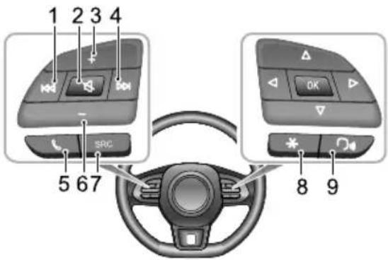
text_image
1 2 3 4 SRC 5 67 8 9I Button
Whenplayingaudio,shortpresstoreturntothe beginningofthetrack(excepttheBluetoothmusic mode),shortpressagaintoswitchtoprevioustrack, andlongpresstorewind(excepttheBluetoothmusic mode)Whenplayingvideo,shortpresstoswitch topreviousvideoandlongpresstrewindWhen playingadioshorpressautomaticallysearchfor
thepreviousstation;longpresstomanuallysearchfor thepreviousstation.
Buttan
Mute/Unmute.
VolumeUpButton
4Button
Whenplayinganaudio/video,shortpresstoswitch toexaudio/vide(exceptBluetoothmusic mode),andlongpresstofastforward.Whenplaying radio,shortpresstoautomaticallysearchforthenext station;longpresstomanuallysearchforthenext station.
Button
Shortpresstohangupifincalling/talkingstate;short presstoanswerandlongpresstorejectifinincoming callstate.
VolumeDownButton
SRCAudioSourceSwitchButton
Switchtothenextavailablemediaaudiosource.
AIRCONDITIONINGANDAUDIOSYSTEMS
8“*”ShortcutButton
“*”buttononthesteeringwheelcanbesetasthe shortcutkeyofSmartPhone/Home/Car.
9SpeechRecognitionFunctionButton
Activate/NCancelspeechrecognitionfunction.This buttonwillonlybeusedafterV vehicle-MobilePhone Interconnection * isenabled.
Note: Somemodelsdonotfeaturesteeringwheel controlbuttons, in these cases all functions described in this chapter that are associated with steering wheel control buttons donotapply.
VolumeAdjustment
Theaudiovolumecanbeadjustedbythecontrolpanel andthebuttonsonthesteeringwheel.Duringthevolume adjustment,thesystemautomaticallypopsupavolume indicationwindowwhichchangessmoothlywiththe adjustmentprocess.
Note: The volume button on the steering wheel and control panel can only be used for the volume adjustment of audios of media and communication type.
Note: The playback volume of Bluetooth music can be adjusted by the device itself and the Infotainment player.
AIRCONDITIONINGANDAUDIOSYSTEMS
Connecting/DisconnectingaUSBStorage Device
InsertingaUSBStorageDevice
ConnectaUSBdevicetotheUSBportforconnection.
RemovingaUSBStorageDevice
Checkandconfirmthatthereisnodatabeingaccessed, thenpullouttheUSBstoragedevice.
Note: If datalossordamagetothestoragedevice occurs for any reason, the data will generally never berecovered. Ford damages, costsorexpenses dueto datalossordamage, the manufacturer assumes no responsibility.
Note: Some USBstoragedevices maybe unidentifiable.
Note: The Infotainmentsystemmaynotachieveits optimum performance when using with some USB storage devices.
Note: Using USB huborextensioncablemaynot identifyUSBdevice.
AIRCONDITIONINGANDAUDIOSYSTEMS
BluetoothPhone
Instructions
- ConnectiontoallmobilephonesfeaturingBluetooth wirelessstechnologyisnotguaranteed.
- Themobilephoneusedmustbecompatiblewiththe InfotainmentsystemsothatallfunctionsofBluetooth phoneofthesystemcanfunctioncorrectly
- When using Bluetooth wireless technology, the Infotainmentsystemmay not operate all functions on the mobile phone.
- WhentransmittingvoiceanddataviaBluetooth technology,thestraight-linedistancebetweenthe Infotainmentsystemandthemobilephoneshouldnot exceed 10metres.However,theactualtransmission distancemaybebeshorterthantheestimateddistance, dependingontheusageenvironment.
- IfPrivatemodeisselectedonthemobilephone, hands-freecallfunctionwillbedisabled.
- Whenthelnfotainmentsystemisturnedoff, the Bluetoothconnectionwillbedisconnected.
- DuetoBluetoothwirelessconnection, interruptionor erroroccurringintheprocessoftransmissioninsome extremecases, and the Infotainmentsystem maybe unable to be paired and connected with the mobile phone. At this time, it is recommended to clear the paired devices in the device of a list on the mobile phone and the Infotainmentsystem and on a pair again.
AIRCONDITIONINGANDAUDIOSYSTEMS
BluetoothPairingandConnection
IfBluetoothisnotenabled,noBluetoothiconisdisplayed inthestatusbar;ifBluetoothisenabledbutnodeviceis connected, isdisplayedinthestatusbar;ifBluetoothis enabledandanydeviceisconnected,isdisplayedinthe statusbar.
ThestepsofBluetoothpairingandconnectionareas follows:
- Touch[Bluetooth]intheSettingsinterfaceoenter theBluetoothconnectionsettingsinterface,andtouch \$ ontheBluetoothbartoenabletheBluetooth function.
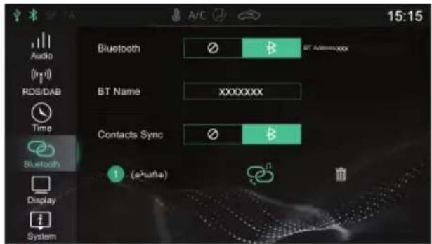
text_image
Audio RDS/DAB Time Bluetooth Display System A/C 15:15 Bluetooth BT Address XXXX BT Name XXXXXXXX Contacts Sync (a-harle)- ThesystemdisplaytheBluetoothaddressandthe devicename.
- EnabletheBluetoothonthemobilephoneandsearch forthelnfotainmentsystemforpairing. Themobile phonewillreceiveaBluetoothPairingrequest,afterthe pairingiscompleted,apromptmessageofConnection Completedwillappear .Ifthepairingfails,pleaserepeat theabovesteps.
- Touch toconnecttothemobilephoneBluetooth, andtouchto disconnecttheBluetooth. Touch removethemobilephonefromthelistofpaireddevices.
AIRCONDITIONINGANDAUDIOSYSTEMS
Keypad
Touch[Keypad]intheBluetoothPhoneinterfacetoenter theDialPadinterface.
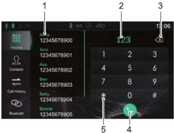
text_image
1 2 3 1:06 123 1 2 3 Arma 12345678900 Arno 12345678901 Asa 12345678902 Ben 12345678903 Betty 12345678904 Bonnie 12345678905 Contacts Call History BluetoothIAddressList/PairedContacts
2InputBox
3Back/DeleteButton
4MakeaCall
Touch tomakeacall;whentheBluetoothphoneis connected,touchtoendthecall.
5InputKeypadArea
Input figures and symbols.
AIRCONDITIONINGANDAUDIOSYSTEMS
Contacts
Touch[Contacts]intheBluetoothPhoneinterfacetoenter theContactsinterface.
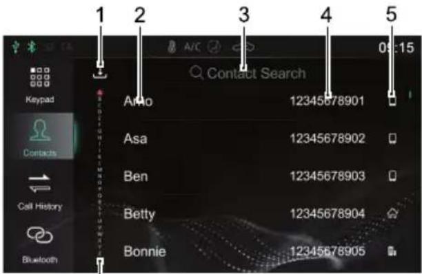
text_image
1 2 3 4 5 Contact Search Aro 12345678901 Asa 12345678902 Ben 12345678903 Betty 12345678904 Bonnie 12345678905 Keypad Contacts Call History Bluetooth6
I DownloadContacts
WhenconnectedtoamobilephoneviaBluetooththe entertainmentsystemdefaultsettingwillautomatically downloadyourcontacts.TheAutoContacts
Downloadfunctioncanbedisabledorenabledinthe BluetoothSettingInterface.
Touch, intheContactsinterfacedownloadthe Contactsmanually.
2 ContactName
3SearchforaContact
Touch[ContactSearch]intheinterface,inputthe initialletterofthenametobesearched,afterthe searchiscompleted,touchthecontacttomakeacall.
4PhoneNumber
5PhoneType
Whenacontacthasmultiplephonenumbers,touch ,ortoswitchthephonenumbertypeand selectthephonenumbertomakeacall.
6QuickContactSearch
T ouchtheletterontheleftoftheinterfaceorswipe thescreentoquicklylocatethecontactwiththisletter astheinitialletter.
AIRCONDITIONINGANDAUDIOSYSTEMS
Note: Forsomemobilephones, adialogboxasking whethertodownloadBluetoothphonecontactswill popupbeforeddownloadingtheBluetoothphone contacts.
Note: Sincethesystemtemporarilydoesnotsupport somecommerciallyavailablemobilephones, the case ofnosynchronisationofBluetoothphonebookwill occuronnonsupportedphones.
Note: Newcontactsthatareaddedwillnotbe displayeduntilthenextsyncronisationiscarriedout.
CallHistory
Touch[CallHistory]intheBluetoothPhoneinterfaceto entertheCallHistoryinterface.
Touchtherequiredcallhistoryrecordinthelisttocallthe contact.
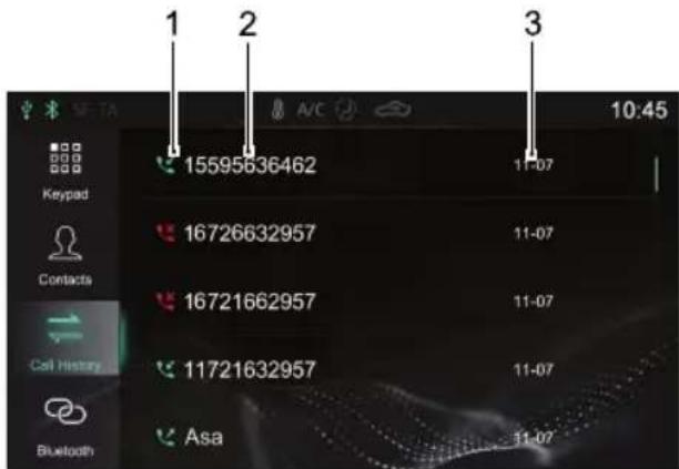
text_image
1 2 3 10:45 15595636462 AVC Keypad 11-07 16726632957 11-07 16721662957 11-07 11721632957 11-07 Asa 11-07 Contacts Call History BluetoothICallHistoryType
DialedCalls:
ReceivedCalls:


AIRCONDITIONINGANDAUDIOSYSTEMS
MissedCalls:

2ContactName/PhoneNumber
3T alkTime
CallHistoryisarrangedbytimeanddateinreverse chronologicalorder.
BluetoothConnection
Touch[Bluetooth]toentertheBluetoothConnection interface. Referto"BluetoothPairingandConnection" in thissectionfordetails.
MakingaCall
Y oumaymakeacallusingthefollowingmethods:
- KeypadInput:Referto"Keypad"inthissectionfor details.
- CallthenumberinContacts:Referto"Contacts"in thissectionfordetails.
- CallthenumberinCallHistory:Referto"CallHistory" inthissectionfordetails.
• Makeacalldirectlyonthemobilephone.
EndingaCall
Y oumayendacallusingthefollowingmethods:
•T ouch 📤 tohangup.
•Shortpress 📞 onthesteeringwheeltohangup.
• Hanguponthemobilephone.
Note: It is illegal to operate mobile telephone whilst driving. If you wish to make, or take a call using your mobile phone directly, please ensure you pull over in suitable location and operate them mobile phone where it is safe and legal to do so.
AIRCONDITIONINGANDAUDIOSYSTEMS
IncomingCall
AnsweranIncomingCall
•T ouch 📞 toansweranincomingcall.
- Shortpress buttononthesteeringwheeltoanswer anincomingcall.
•Answeranincomingcallonthemobilephone.
RejectanIncomingCall
Note: It is illegal to operate mobile telephones whilst driving. If you wish to make, or take a call using your mobile phone directly, please ensure you pull over a suitable location and operate them mobile phone where it is safe and legal todos.
SwitchtoPrivateMode
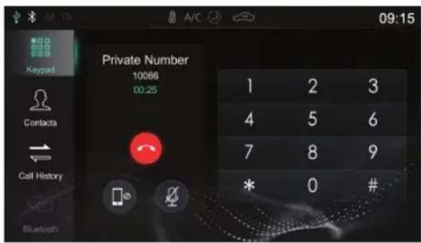
text_image
Private Number 10086 00:25 1 2 3 4 5 6 7 8 9 * 0 #Duringacall,touchtoenterthePrivateMode (SpeakerModebydefault).
Duringacall,touchtorestoretheSpeakerMode.
Duringacall,touchtoswitchbetweenMicrophone MuteorEnabledfunction.
I Privat Mode, mayontinu with the allsing themobilephone, hespeakers and microphone of the
AIRCONDITIONINGANDAUDIOSYSTEMS
Infotainmentsystemwillbemuted.ButBluetoothisstill connected.
Note: It is illegal to operate mobile telephone whilst driving. If you wish to make, or take a call using your mobile phone directly, please ensure you pulloverina suitable location and operate them mobile phone where it is safe and legal todos.
Entertainment
PrecautionsforPlayingaStorageMediumMode
- ThesystemsupportsUSBdrivesandBluetoothstorage media.
- If the USB device media is not in use, DONOT leave the device connected. This may result in connection deterioration.
- DonotremoveUSBdeviceIdwhilstmediaisplaying. Failuretofollowtheseinstructionscouldresultin corrupteddata.
- KeeptheUSBportdryandfreefromdebris.Theport willbecomeunusableifitisblocked.
Radio
TouchtheRadio/Musicareainthemaininterface,and touch[Radio]againtoentertheRadiointerface.
T olistentothebroadcastingofdifferentbands,touch [DAB] *,[FM]or[AM]intheplaybackinterfacetoswitch betweenDAB * andradiobands.PressingtheSRCbutton canalsoswitchbetweenthedifferentradriobands.
DAB *
AIRCONDITIONINGANDAUDIOSYSTEMS
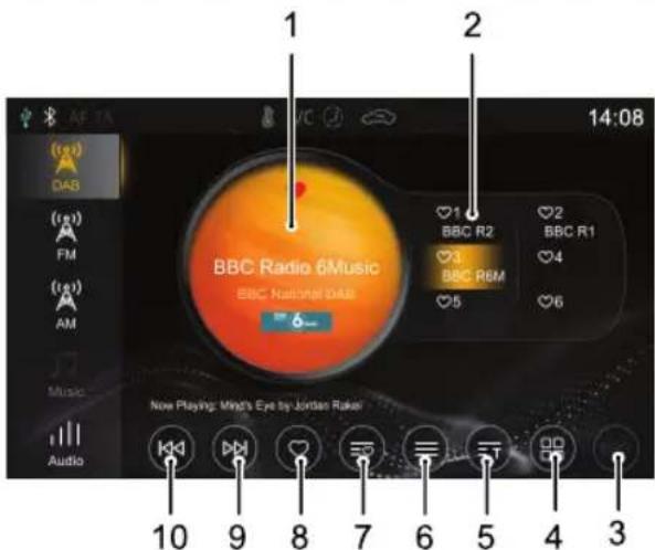
text_image
1 2 14:08 BBC Radio 6Music BBC National DAB ♥1 BBC R2 ♥2 BBC R1 ♥3 BBC R&M ♥4 ♥5 ♥6 Now Playing: Mind's Eye by Jordan Raker 10 9 8 7 6 5 4 3I CurrentStationNameorFrequency
Touch[DAB],[FM]or[AM]toswitchtheband.
2DisplayofFavoriteStations
3ElectronicProgramGuide
4DABCategoriesList
5Radioinformation
T ouchingthebuttonwilldisplayradioinformation, suchastext,picture.
6StationList
7ListofFavoriteStations
8AddaStationto/RemoveaStationfromFavorites
9NextStation
Shortpresstoautomaticallysearchforthenext station;longpresstomanuallysearchforthenext station.
10PreviousStation
Shorpressautomaticallysearchfortheprevious station;longpresstomanuallysearchfortheprevious station.
AIRCONDITIONINGANDAUDIOSYSTEMS
FM/AM
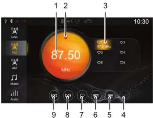
text_image
1 2 3 10:30 87.50 MHz (1g) DAB (1g) FM (1g) AM Music Audio 9 8 7 6 5 4I CurrentStationNameorFrequency
Touch[DAB],[FM]or[AM]toswitchtheband.
2StationFavoritesState

indicatesthatthestationhasbeenaddedto
Favorites; indicate that the station is not added to favorites.
3DisplayofFavoriteStations
4Radiolnformation
T ouchingthebuttonwilldisplayradioinformation, suchastext,picture.
5StationList
6ListofFavoriteStations
7AddaStationto/RemoveaStationfromFavorites
8NextStation
Shortpresstoautomaticallysearchforthenext station;longpresstomanuallysearchforthenext station.
9PreviousStation
Shorpressautomaticallysearchfortheprevious station;longpresstomanuallysearchfortheprevious station.
Touch[Audio]rthisinterfaceandthesystemskipsthe AudioSettingsinterface.
AIRCONDITIONINGANDAUDIOSYSTEMS
USBMusic
InsertaUSBstoragedeviceintotheUSBport,andthe systemautomaticallyloadsthemusicfromthestorage device.
TouchtheRadio/Musicareainthemaininterface,and touch[USBMusic]againtoentertheUSBMusicPlayback interface.
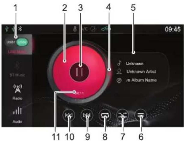
text_image
1 2 3 4 5 09:45 USB1 USB2 USB Music BT Music Radio Audio Unknown Unknown Artist in Album Name 11 10 9 8 7 6IUSBDrive
WhentherearetwoUSBdrives,youmaychooseto playmusicinUSBI or USB2.
2AlbumCover
3Play/Pause
4T rackPlaybackProgressBar
T rack playback progress is displayed by the coil, drag the progress bartoskiptocertain playing point.
5Song/Artist/AlbumName
6USBMusicList
TouchcenterthecorrespondingFolderListinterface, thentouchtoselectandplaythetrackyouprefer.
7RandomPlaybackMode
Y oumayswitchbetweenRandomPlaybackandFolder RandomPlayback.
8LoopPlaybackMode
Y oumayswitchbetweenSingleLoop, FolderLoopand LoopAll.
AIRCONDITIONINGANDAUDIOSYSTEMS
9NextT rack
Shortpresstoswitchtothenexttrack;longpressto fastforward.
10PreviousTrack
Shortpresstoswitchtotheprevioustrack;short pressduringplayingtoreturntothebeginningofthe track;longpresstofastrewind.
I I CurrentElapsedTime
Touch[Audio]inthisinterface,andthesystemskipstothe AudioSettingsinterface.
BluetoothMusic
PleaseconnectaBluetoothdevicefirstbeforeplaying Bluetoothmusic.Referto"BluetoothPairingand Connection"in"BluetoothPhone"sectionfordetails.
AftertheBluetoothdeviceisconnectedwiththesystem, touchtheRadio/Musicareainthemaininterface,andthen touch[BTMusic]toentertheBluetoothMusic playback interface.
AIRCONDITIONINGANDAUDIOSYSTEMS
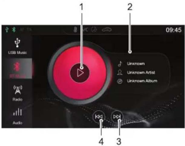
text_image
USB Music 09:45 1 2 Unknown Unknown Artist Unknown Album Radio Audio 3 4IPlay/Pause
2Song/Artist/AlbumName
3NextT rack
4PreviousT rack
Touch[Audio]inthisinterface,andthesystemskipstothe AudioSettingsinterface.
USBVideo
InsertaUSBstoragedeviceintotheUSBport,andthe systemautomaticallyloadsthevideosfromthestorage device.
Note: Duetodifferencesinthecompressionratio and bitrateofthemultimediaformatsdownloadedfrom theInternetandotherfactors,theactualsituationof thedecodingresultshallprevail.
Note: Foryourdrivingsafety, when the vehicles speed reaches ascertain value, the videos safety modewill be activated automatically, the video cannot be played at that moment.
Note: The video cannot be played during acall.
Touch[Video]inthemaininterfacetoentertheVideo Playbackinterface.
Note: When playing a video, touch the screentowake upthemenubarmode, and touch it again to exit the menubarmode.
AIRCONDITIONINGANDAUDIOSYSTEMS
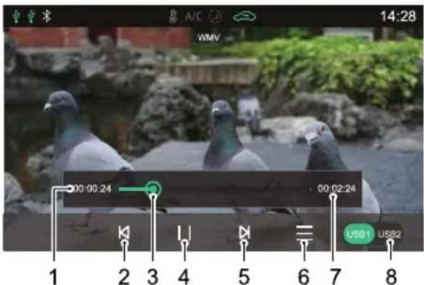
text_image
14:28 WMV 00:00:24 00:02:24 USB1 USB2 1 2 3 4 5 6 7 8I Current Elapsed Time
2PreviousVideo
Shortpresstoswitchtothepreviousvideo;longpress tofastrewind.
3PlaybackProgressBar
Dragtheprogressbartoskiptocertainplayingpoint.
4Play/Pause
5NextVideo
Shortpresstoswitchtothenextvideo;longpressto fastforward.
6VideoList
Y oumayviewandplaythecorrespondingvideofile.
7T otalVideoDuration
8USBDrive
When there are two USB drives, you may choose to play videos in USB I or USB2.
AIRCONDITIONINGANDAUDIOSYSTEMS
Pictures
InsertaUSBstoragedeviceintotheUSBport,andthe systemautomaticallyloadsthepicturesinthestorage device.
Touch[Pictures]inthemaininterfacetoenterthepicture Playbackinterface.
T ouchapicturefiletodisplayitinfullscreen.
Note: Whilstviewingapicturefile,touchthescreen towakeupthemenubarmode,andtouchitagainto exitthemenubarmode.
PictureBrowsingInterface
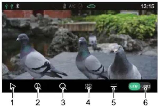
text_image
13:15 USB1 USB2 1 2 3 4 5 6I SlideShow
2ZoomIn
3ZoomOut
4Thumbnail
5PicturesList
Y oumayviewandplaythecorrespondingpicturefile.
AIRCONDITIONINGANDAUDIOSYSTEMS
6USBDrive
WhentherearetwoUSBdrives,youmaychooseto viewpicturesinUSBI orUSB2.
Note: Thesystemsupportstheviewingofpictures storedonaUSBdevice.Duetodifferencesinpicture resolution, formatcompressionratioandsomeother factorsnotallpicturesmaybedecodedanddisplayed.
Note: Swipetotheleftorrightonthescreentoswitch tothenextorpreviouspicture.
Vehicle-MobilePhoneInterconnection \*
OnlyapplicabletomodelsthatfeatureVehicle-Mobile PhoneInterconnection.
AppleCarPlay \*
AppleCarPlayenablesinformationinteractionbetween themobilephoneandtheon-boardInfotainmentsystem, includingmap,music,telephone,shortmessage,podcast, voicerecognition.
ConnectionMethod
I Confirm that your mobile phone has the Car Play function and that it is turned on.
2ConnectthemobilephonetothInfotainmentsystem mainframeusingasuitableUSBcable.
3Inthemaininterface,touch[AppleCarPlay] * areato entertheAppleCarPlayinterface.
4Afterthevehicleandmobilephonearesuccessfully connected,youcanoperatetheiPhoneusingthe Infotainmentsystemscreen.
AIRCONDITIONINGANDAUDIOSYSTEMS
5PresstheHOMEbuttononthecontrolpaneltoreturn tothemainsysteminterface.
AndroidAuto \*
AndroidAutoenablesinformationinteractionbetween theandroidmobilephoneandtheon-boardInfotainment system,includingmap,music,telephone,messages,voice commands.
Fortheinitialapplication, download and install Android AutoAPP to your mobile phone from the market in which it will be operating.
Whenusing, connectthemobilephonetothe InfotainmentsystemmainframeusingasuitableUSBcable. Inthemaininterface,touch[AndroidAuto] * areato entertheAndroidAutointerface.Operateaccordingto theinterfaceprompt,thenyoucanusethefunctiononce theconnectionissuccessful.
A/C
TouchtheA/Careainthemaininterfacetoenterthe A/SystemSettingInterfaceElectronic TemperatureControl"inthisManualfordetails.
VehicleSettings
Touch[Car]inthemaininterfacetoentertheVehicle Settingsinterface.
DrivingAssist \*
Touch[DrivingAssist]intheV ehicleSettingsinterfaceto entertheDrivingAssistSettingsinterface.Y oucansetup thedrivingassistancesystem.
ComfortConvenience
TouchComfortConvenience Vehicle Settings interface with ComfortConvenience Settings interface where the lights and other functions can be set.
DrivingMaintenance
ToudDrivingMaintenanceEehicSettings interface:teDrivingMaintenanceSettings interface.Y oucansetupsomedrivingcontrolsystems.
FactorySetting
Touch[FactorySetting]intheV vehicleSettingsinterfaceto entertheRestoreFactorySettingsinterface.
AIRCONDITIONINGANDAUDIOSYSTEMS
Touch[Reset]intheFactorySettingsinterface,andaReset promptappears.Pleaseselectasneeded.Pleaseusewith caution.
Settings
Touch[Setup]inthemaininterfacetoentertheSettings interface.
AudioSettings
Touch[Audio]intheSettingsinterfacetoentertheSound Settingsinterface.Y oucansetthevolume,EQandsound stage.
RDS/DABSettings \*
Touch[RDS/DAB]intheSettingsinterfacetoentertheRDS/DABSettingsinterface.Y oucansettheRDS/DAB relatedfunctions.
Time&DateSettings
Touch[Time]intheSettingsinterfacetoentertheTime&DateSettingsinterfacetosetthedateandtime.
BluetoothSettings
Touch[Bluetooth]intheSettingsinterfacetoenter theBluetoothSettingsinterfacetosettheBluetooth
AIRCONDITIONINGANDAUDIOSYSTEMS
connectionfunction.Referto"BluetoothPairingand Connection"inthissectionfordetails.
DisplaySettings
Touch[Display]intheSettingsinterfacetoenterthe DisplaySettingsinterface.Y oucansetthebrightness, backlightmodeandunits.
SystemSettings
Touch[System]intheSettingsinterfacetoenterthe SystemSettingsinterface.
- Y oucanviewthehelpfile,softwareversion,hardware versionandotherinformationofthesystem.
- Touch[Start]toenterRestoreFactorySettings interface,youcanselecttorestoreAudio,Radiolists,OtherorAlltodefaultfactorysettingsasrequired. Afterrestoringfactorysettings,themainframeisreset toitsoriginalsettingsandalldataintheInfotainment systemwillbedeleted.Pleaseusewithcaution.
Seats&Restraints
108Seats
113SeatBelts
124 AirbagSupplementaryRestraint System
133ChildRestraints
SEATS&RESTRAINTS
Seats
Overview

To avoid personal injuries dueto the loss of control, DONOT adjust these at while the carismoving.
The vehicle is equipped with 6-direction or 4-direction adjustable front seats and 60/40 split rear seats with foldable backrests.
Anidealpositionoftheseatshouldmakesureyourdriving positioniscomfortable,whichallowsyoutoholdthe steeringwheelwithyourarmsandlegsslightlybentand controlalltheequipment.Makesureyourdrivingposition iscomfortableandenablesyoutomaintainfullcontrol ofthevehicle.T akecarewhenadjustingtheheightof frontseats-thefeetoftherearpassengercouldbecome trappedwhenteseatislowered.
Donotinclinethefront-seatbackrestexcessively. Optimumbenefitisobtainedfromtheseatbeltwiththe backrestanglesettoapproximately25°fromtheupright (vertical). Thedriverandfrontpassengerseatsshould
bepositionedasfarrearwardaspractical. A properly adjusted seathelps reducetheriskofinjury from sitting to ooclosetoaninflating airbag.
HeadRestraints

Adjusttheheightoftheheadrestraintsothat thetopofitisinlinewiththetopofthe occupant'shead. Thislocationmayreduce theriskofheadandneckinjuriesintheevent ofacollision.DONOTadjustorremovethe headrestraintswhilethecarismoving.

DONOThanganythingonanyheadrestraint orheadrestraintrod.
Theadestraidesignedpreventearward movementoftheheadintheeventofacollisionor emergencybraking,therebyreducingtheriskofheadand neckinjuries.
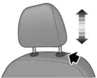
natural_image
3D illustration of a car headrest with directional arrows indicating movement or change (no text or symbols)Whenadjustingaheadrestraintfromlowtohighposition, pulltheheadrestraintdirectlyupward,andgentlypress itdownwardafteritreachesthedesiredposition to makesurethatitislockedinposition.T oremovethe headrestraint,pressandholdtheguidesleevebutton(as indicatedbythearrow)ontheleftoftheheadrestraint, thenpulltheheadrestraintupwardtoremoveit.
Whenadjustingaheadrestraintfromhightolowposition, presstheguidesleevebutton(asindicatedbythearrow)on theleftoftheheadrestraint,andpresstheheadrestraint downward;releasethebuttonafteritreachesthedesired position,andgentlypresstheheadrestraintdownwardto makesurethatitislockedinposition.
FrontSeats
ManualSeat
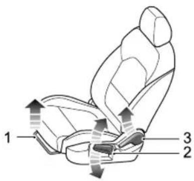
text_image
1 2 3•Forward/BackwardAdjustment
Liftthelever(1)undertheseatcushion, slidetheseat intoanappropriatepositionandreleasethelever. Make surethattheseatislockedinplace.
• CushionHeightAdjustment
SEATS&RESTRAINTS
Liftthelever(2)repeatedlytoraisetheseatcushion, andpresstheleverdownwardtolowertheseat cushion.
- BackrestAdjustment
Liftthelever(3),adjustthebackrestuntilimovesinto asatisfiableposition,andputdownthelever.
PowerSeat *
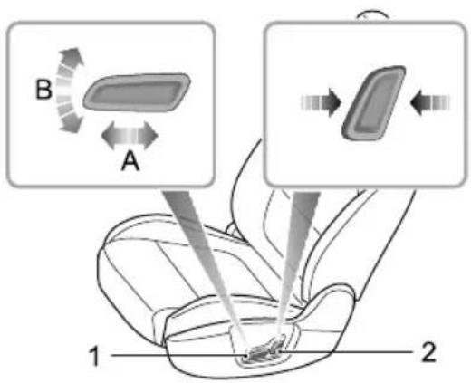
text_image
B A 1 2•Forward/RearwardAdjustment
Pushtheswitch(I)forwardorbackward(A)tomove theseatforward/backward.
• CushionHeightAdjustment
Pulltheswitch(I) upward or pushdownward(B) to raise or lower these at cushion.
- BackrestAdjustment
Movetheswitch(2)forward/backwardtoadjustthe backrestuntiltreachesthedesiredangle.
RearSeats
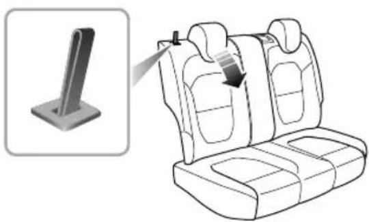
natural_image
Diagram of a car seat assembly with a magnified inset showing the side view of the seat (no text or symbols present)FoldingRearSeats
T oincreaseluggagespace,firstfullylower(orremove)all therearseatheadrestraints,andthenpullupthebackrest unlockstrapsonbothsidesrespectivelyandfoldtheseat backrestsforward.
Note: Whentheheadrestraintoftherearseatis notfullyloweredorthebackrestofthefrontseatis
inclinedbackwardexcessively, the folding of therear seatis very likely to damagetheback of the front seat, small storage compartmentorhead restraint of the rearseat.
UnfoldingandLockingRearSeatBackrests
When returning therearseatbackresttotheupright position, pullupthebackrestunlockstrapstorelease thelockedstate, pushthebackrestuntilreachesan appropriateposition, and thebackrestislockedwhenyou hearaclick.
Note: When returning there are seat back rest to the desired position, makes sure that there are seat belt is not trapped.
FrontSeatHeating \*

Ifbareskinisincontactwiththeheatedseats forexcessiveperiodsoftime,itmaycause burns.
SEATS&RESTRAINTS
Theseatcushionandbackrestareprovidedwithheating elements. Afterstartingtheengine,pressingorwill activatetheheaters.
Whenpressingaseatheaterswitch, the corresponding seatwillbecomewarm. Presstheswitchagaintostop theheatingfunction. Whentheseatheatingfunctionis activated, theoperatingindicatorintheswitchilluminates. Whenthecushiontemperaturereachesapproximate38°C orthebackresttoapproximate40°C, theheatingfunction willbedeactivatedautomatically.
IMPORTANT
- Do Not cover the heated salt with blankets, cushions or insulation type objects or materials.
- If theseatcushionisheatedupto38°Corthe seatbackrestisheatedupto40°Candcontinues gettinghotterwhenusingseatheatingsystem,please turnofftheseatheatingandcontactMGAuthorised Repairer.
• Overuseofthedriver'sheatedseanaycause drowsinessandcouldaffectsafety.
SeatBelts

It is important that all seat belts are worn correctly. Always check that all passengers are wearing seat belts. DONOT carry passenger that are unable to wear correctly positioned seat belts. Wearing seat belts incorrectly may cause serious injury over death in the event of a collision.

Airbags cannot replace seatbelts. Airbags can only provide extrasupport when triggered by all accidents will trigger airbag whether airbags are triggered not seabels can reduce the risk of serious injury or death in accidents. Therefore, seatbelts must beworn properly.

NEVERinfasteneabelvilsdriving, seriousinjuryordeathmayoccurinthecase ofanaccidentoremergencybraking.

NEVERfastenthedriverseatbeltoruse buckleplacementedgeriver seaitacanowhenexitingvehicle. Thisukhuskinginstart automatically.

Thisvehicleisequippedwithseatbeltwarning indyoutofastenyourseatbelt.
During driving seat belts must be fastened, this because: You came to predict you will be involved in collision accident and how serious it maybe. Many cases of collision accidents with seat belts properly fastened are well-protected, while passengers with seat belts not fastened suffer from serious injury or evendeath. Therefore, all passengers must wear seat belts correctly, even during short-distance journeys.
SEATS&RESTRAINTS
ProtectionProvidedbySeatBelts

Itisofequalimportanceforpassengersinthe rearseattofastentheirseatbeltscorrectly. Otherwise,passengerswithseatbeltsnot correctlyfastenedwillbethrownforwardin accidents,andwillendangerthemselvesas wellasthedriverandotherpassengers.
Whenthevehicleisinmotion,thetravellingspeedofthe occupantsisidenticaltothatofthevehicle.
Intheeventofa'headoncollision'oremergencybraking, thevehiclemaystop,buttheoccupantswillcarryon travellinguntiltheycomeintocontactwithastationary object.Thisobjectmaybetheeeringwheel,dashboard, windscreenorfrontseats.
Acorrectlyfastenedseatbeltwilleliminatethisriskof injury. Whentheseatbeltisworncorrectly, itwilllock automaticallyincollisionaccidentsoremergencybraking toreduceyourspeedtogetherwiththevehicle, soas topreventtheout-of-controlmovementwhichmaycause seriousinjurytodriverandpassengers.
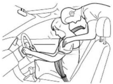
natural_image
Line drawing of a car interior showing a person seated in a seatbelt, with another hand adjusting the seat (no text or symbols)SEATS&RESTRAINTS
WearingSeatBelts

Incorrectlywornseatbeltscouldcauseinjury ordeathintheeventofanaccident.

Seatbeltsaredesignedforoneperson,DO NOTshareseatbelts.

DONOTwrapaseatbeltaroundwhen holdingababyorchildinyourarms.

Removeanyheavycoatsorclothingwhen wearingaseatbelt,failuretodosocanaffect protectionprovidedbytheseatbelt.

Seatbeltsshouldnotbewrappedaround hardorsharpobjectssuchaspens, spectacles orkeys.

Seatbeltscannotfunctioncorrectlywhenthe seatsarereclinedexcessively.DONOTdrive whentheseatsareexcessivelyreclined.
Theseatbeltsfittedtoyourvehiclearedesignedforuse bynormalsizedadults. Thispartoftheliteraturerefersto adultuse.
Allseatbeltsare3pointlap-diagonalbelts.
Inordertomaintaineffectiveprotection, thepassengers mustsitinthecorrectorientation, feetplacedonthefloor infrontofthem, withanuprightbody(noexcessiverecline) andtheseatbeltcorrectlyfastened.
SEATS&RESTRAINTS
FasteningSeatBelts
Please follow the instructions below to fast these seat belts correctly.
I Adjusttheseatcorrectly.
2Holdthemetaltab, pulltheseatbeltoutsteadilyover theshoulderandacrossyourchest. Ensurethereisno twistonthebelt.
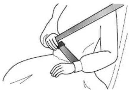
natural_image
Illustration of a person using a bandage to lift a sword (no text or symbols present)3Insertthemetaltabintothebuckleuntilyouheara 'click', this indicates these at belt is securely locked.
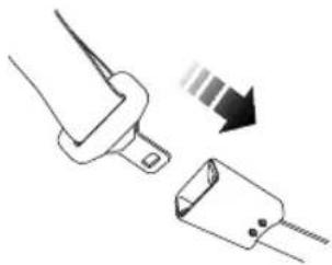
natural_image
Diagram showing a connector with a downward arrow indicating compression or dislocation (no text or symbols present)4Removeanyslacknessinthebeltbypullinguponthe diagonalsectionofthebelt.
5T oreleasetheseatbelt, presstheredbuttononthe buckle. Theseatbeltwillretractautomaticallytoits originalplace.
IMPORTANT
•Alwaysensuretheseatbeltwillnotbecometrapped inthedooraperturewhenclosingthedoor ,damage willoccur.
- Pullingtheseatbeltouttooquicklymaycauseit tolock.Inthiscase,allowtheseatbelttoretract slightlyandthenpullitacrossyourbodyslowly.
•Ifitisdifficulttopulltheseatbeltout,itmaybedue totwistedwebbing.Ifthisisthecase,fullyextract theseatbelt,removethetwist,allowtheseatbelt toretractslowly.
- Whenusingtherearseatbeltspleaseensurethey arefullyretractedintothecorrectpositionto avoidjammingintherearseatcatches.Itisalegal requirementtowearseatbelts.Eveniftheseatbelt istwisteditmustbeworn.Wherepossibleavoid thetwistedsectioncontactingthebodyandseek advicefromanMGAuthorisedRepairerassoonas possible.
CorrectRoutingoftheSeatBelts

Ensuretheseatbeltiscorrectlypositionedon thebody,nevercrosstheneckorabdomen, neverpasstheseatbeltbehindthebackor underthearms.
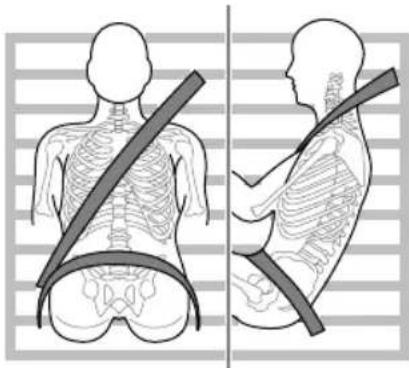
natural_image
Side-by-side illustrations of human torso and neck showing skeletal contours and a belt (no text or symbols)Whenwearingseatbelts,thelapbeltsectionsshouldbe positionedaslowaspossibleacrossyouhipsneveracross theabdomen.Intheeventofacollision,thelapbeltcan applyaforceonthehipsandreducethepossibilityofyou
SEATS&RESTRAINTS
slippingunderthelapbelt. If you slip under the lap belt, the belt will apply force your abdomen, which may cause serious or fatal injuries. Thediagonal section of the belt should cross them middle of the shoulder and the chest. In the event of emergency braking or collision, the diagonal section of the belt will be locked.
To ensure that these seat belts always provide maximum protection, ensure the belt is flat, not loose and contacts the body.
SeatBeltsUseduringPregnancy
Wearingcorrectlypositionedseatbeltswillprovide protectionforbothmotherandunbornchildintheevent ofacollisionoremergencybraking.
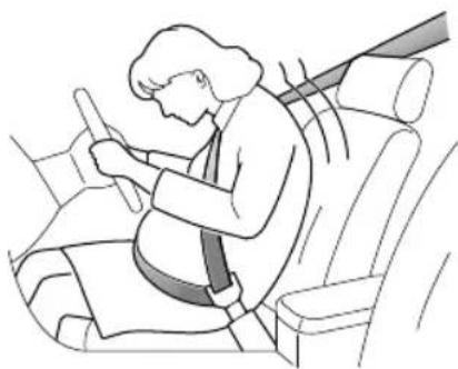
natural_image
Illustration of a person sitting in a car seat, wearing a seatbelt and using a device (no text or symbols present)Thediagonalsectionoftheseatbeltshouldpassacross thechestasnormal,thelapsectionofthebeltshouldpass belowthebelly,lowandsnugonthehipbones.NEVER positionthebeltonorabovethebelly.
Please consult your physician for further details.
SeatBeltsandDisabilities
Itisalegalrequirementthatallooccupantswearseatbelts, thisincludepeoplewithdisabilities.
Depending upon the disability, consult your physician for further details.
SEATS&RESTRAINTS
ChildrenandSeatBelts

Properprotectionmeasuresmustbetaken forchildrenwhilsttravellinginthevehicle.
Forsafetyreasons, childrenmusttravelissuitablechild restraintdevicesfixedtotherearseat.
Infants

Only recommended child restraint suitable for the age, height and weight of the child should be used.

NEVERcarryachildorinfantwithyourarms duringdriving. Whencollisionaccidents occur, theweightofachildwillproducesuch agreatforcethatyoucannotholdthechild. Thechildwillbethrownforwardandsuffer seriousinjuryorevendeath.
Theseatbeltsfittedtoyourvehiclearedesignedforadults, theyarenotsuitableforchildren.Intheeventofan accidentorcollisionthechildrenarenotsecure,itcould causedeathorseriousinjury.
InfantsMUSTuseasuitablechildrestraintdevice.Please consultthechildseatmanufacturersguidelineswhen selectingthecorrectsefollowthemanufacturers instructioninstallationPleaseRefChild Restraints"inthischapterformoredetails.
OlderChildren

NEVERshareaseatbeltamongstchildren. Intheeventofanaccidentorcollisionthe childrenarenotsecure,itcouldcausedeath orseriousinjury.
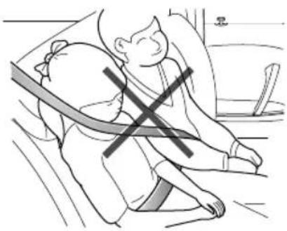
natural_image
Illustration of a person sitting on the floor with a cross symbol indicating pressure or stress (no text or symbols present)SEATS&RESTRAINTS
Aschildrengrowandbecomeolder/larger, it will get to the stagewhentheynolongerrequirechildseatrestraints, at thispoint they will require use of the vehicle standard seat belt. Please ensure these seat belt is correctly positioned on the body of the child.
SeatBeltPre-tensioners

Theseatbeltpre-tensionerswillonly beactivatedonceandthenMUST BEREPLACED.Failuretoreplace the pre-tensionerswillreducetheefficiency of thevehicle'sfrontrestraintsystem.

If the pre-tensioners have been activated, the seat belt will still function as restraints, and must beworn in the event that the vehicle remains in drivable condition. These at beltpretensioners should bere placed at the earliest opportunity by an MAuthorised Repairer.
The vehicle is fitted with seat belt pre-tensioners, these ar designed to be a t on a belt and work
in conjunction with the air bags in the event of a severe collision. They are designed to retract these at belt and secure the occupant in these at.
Theirbagarninglighthinstrumentackwill alerdrivemnalfunctionofseelt pretensioners.(see'WarningLampsandIndicators'inthe 'InstrumentsandControls'chapter).
Theseatbeltpre-tensionerscanonlybeactivatedonce, afteractivationthemusteeplaceThismay also involve replacementofotherSRScomponents.Please refer to'ReplacingAirbagSystemParts'.
IMPORTANT
- Seatbeltpre-tensionerswillnotbeactivatedby minorimpacts.
• Theremovalorreplacementofapre-tensionermust becarriedoutbythemanufacturertrained, dealer technicians. - 10yearsfromtheinitialdateofregistration (orinstallationdateofareplacementseatbelt pre-tensioner),somecomponentswillneedto bereplaced.TheappropriatepageoftheService Portfoliomustbesignedandstampedoncethe workhasbeencompleted.
SeatBeltChed Maintenance and Replacement
SeatBeltChecks

Split, wornorfrayedseatbeltsmaynot functioncorrectlyintheeventofacollision, ifthereareanysignsofdamage,replacethe beltimmediately.

Alwaysensuretheredreleasebuttononthe seatbelbuckleispointingupwardstønsure easyreleaseirtheeventofanemergency.
Pleas follow instruction below we regularly check whether these seat belt warning lamp, seat belt, metal tab, buckle, retractor and fixing levic are working correctly:
- Inserttheseatbeltmetaltabintothecorresponding buckleandpullseatbeltwebbingclosetothebuckle quicklytocheckthatthebeltclasplocks.
- Holdthemetatabandpulltheseatbeltforwardquickly toheck that seelted back automatically, preventing the webbing from extending.
SEATS&RESTRAINTS
- Fullyextracttheseatbeltandvisiblyexaminefortwists, fraying, splitsorwornareas.
- Fullyextracttheseatbeltandallowtoreturnslowlyto ensurecontinualandcompletesmoothoperation.
- Visiblyexaminetheseatbeltformissingorbroken components.
- Ensuretheseatbeltwarningsystemisfullyfunctional. Iftheseatbeltfailsanyoftheabovetestorsinspections contactanMGAuthorisedRepairerimmediatelyfor repairs.
SeatBeltsMaintenance

Seatbeltrepairsshouldonlybecarriedout byanMGAuthorisedRepairer.

Ensure no foreign or sharp objects become lodged in these at belt mechanisms. DO NOT allow liquid to contaminate these at belt buckle, this could affect the buckle engagement.
Seatbeltsshouldonlybecleanedwithwarmsoapywater. Donotuseanysolventtocleantheseatbelt.Donot attempttobleachordyetheseatbelt,itmayweakenthe seatbelt.Aftercleaning,wipewithaclothandallowto dry.Donotallowtheseatbelttofullyretractbeforeitis completelydry.Keepseatbeltscleananddry.
If there are contaminants accumulated in theretractor, the retraction of these at belt will beslow. Please use a clean and dry cloth to remove any contaminants.
ReplacingSeatBelts

Collisionaccidentsmaydamagetheseat beltsystem. Theseatbeltsystemmaynot beabletoprotectusersafterdamageand maycauseseriousinjuryorevendeathwhen anaccidentoccurs. Aftertheaccident,seat beltsshouldbecheckedimmediately and replacedasnecessary.
Seatbeltsshouldnotrequirechangeafterminorcollisions, however, someotherpartsoftheseatbeltsystemmay
SEATS&RESTRAINTS
requireattention.PleaseconsultanMGAuthorised Repairerforadvice.
SEATS&RESTRAINTS
AirbagSupplementaryRestraint System
Overview

TheairbagSRSprovidesADDITIONAL protectioninaseverefrontalimpactonly.It doesnotreplacetheneed,orrequirementto wearaseatbelt.

The airbagstogether with these at belts provide optimum protection for adults, but its not the case for infants. These at belt and air bags systems in the vehicle are not designed for protecting infants. The protection required by infant should be provided by child restraints.
TheAirbagSupplementaryRestraintSystemgenerally consistsof:
- FrontAirbags(fittedtothecentreofthesteeringwheel anddashboardabovetheglovecompartment)
- SeatSideAirbags(fittedtotheoutersideoftheseatsquab)
- SideHeadImpactProtectionAirbags(fittedbehindtheheadlining)
Pleasenotethatthisismodelandtrimleveldependant.
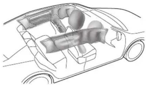
natural_image
Technical line drawing of a car interior showing internal components (no text or labels)Inthecorrespondingpositionwhereairbagsarefitted, thereisawarningsignstating‘AIRBAG’.
AirbagWarningLight

Theairbagwarninglightislocatedinthe
instrumentpack.Ifthislampdoesnotextinguishor illuminatesduringdriving,itindicatesthatthereisafailure intheSRSorseatbelt.PleaseseekanMGAuthorised Repairerattheearliestopportunity.AnSRSorseatbelt faultmaymeanthecomponentsmaynotbedeployedin theeventofanaccident.
AirbagDeployment

Frontseatpassengersshouldnotplacefeet, kneesoranyotherpartofthebodyincontact with, orincloseproximitytoafrontairbag.

Tominimisetheriskofaccidentalinjuryfrom inflatingairbags,seatbeltsshouldoworn correctlyatalltimes.Inaddition,bothdriver andfrontseatpassengersshouldadjusttheir seatoprovidesufficiendistancefromthe frontairbags.Ifsideairbags/sideheadimpact protectionairbagsarefitted,bothdriverand frontseatpassengershoubeseatedto maintainsufficientdistancefromtheupper partofthebodytothesidesofthevehicle, thiswillensuremaximumprotectionwhen thesideairbags/sideheadimpactprotection airbagsaredeployed.
SEATS&RESTRAINTS

Whenairbagsaredeployed, childrenwithout properprotectionmaysufferfromserious injuryorevendeath.DONOTcarrychildren inthearmsoronthekneesduringtraveling. Childrenshouldwearseatbeltssuitableto age.DONOTleanoutofwindows.

Aninflatingairbagcancausefacialabrasions andotherinjuriesiftheoccupantistooclose totheairbagatthetimeofitsdeployment.

DONOTaffixorplaceanyobjectson, or adjacenttotheairbags. Thismay affect the airbagpassageorcreateprojectilesthatmay causeinjuryorseriousharmintheeventof airbagdeployment.

Afterdeploymenttheairbagcomponents becomeveryhot.DONOTtouchanyairbag relatedcomponents,itmaycauseburnsor seriousinjury.

DONOTknockorstrikethepositionwhere airbagsorrelatedpartsarelocated,soas toavoidaccidentalairbagdeploymentwhich maycauseseriousinjuryorevendeath.
Intheeventofacollision, the airbag control unit monitors therate of deceleration or acceleration induced by the collision, todeterminewhether the airbag should be deployed. Airbag deployment is virtually instantaneous and occurs with considerable force, accompanied by a loud noise.
Provided the front seat occupants are correctly seated and with seat belts properly worn, the air bags will provide additional protection to the chest and facial areas in the event of the car receiving a severe frontal impact.
Sideairbagsandsideheadimpactprotectionairbagsare designedtoofferadditionalprotectiontothesideofthe bodyfacingtheimpact,ifaseveresidecollisionoccurs.
IMPORTANT
•Airbagscannotprotectlowerbodypartsof passengers.
- Airbagsarenotdesignedforrearcollision,minor frontalorsideimpacts,orifthevehicleoverturns; norwillitoperateasaresultofheavybraking.
- Deployment and retraction of the frontal and side air bag stakes place every quickly and will not protect against the effect of secondary impact that may occur.
- Whenanairbaginflates,afinepowderisreleased. Thisisnotanindicationofamalfunction,however, thepowdermaycauseirritationtotheskinand shouldbethoroughlyflushedfromtheeyesandany cutsorabrasionsoftheskin.
•Afterinflation,frontandsideairbagsdeflate immediately. Thisprovidesagradualcushioning effectfortheoccupantandalsoensuresthatthe driver'sforwardvisionisnotobscured.
FrontAirbags

NEVERusearearwardfacingchildrestraint onseatprotectedbyanACTIVEAIRBAG infrontofit,DEA THorSERIOUSINJURYto theCHILDcamccur.Referto'Disablingthe PassengerAirbag'.

Frontseatpassengersshouldnotplacefeet, kneesoranyotherpartofthebodyincontact with,orincloseproximitytoafrontairbag.

Inextremecasesdrivingnveryuneven surfacesaycausirbagdeployment. Pleasetakeextracarewhendrivingon unevenroads.
Airbagsaredesignedtodeployduringseriousimpacts,the followingconditionsmaycauseairbagdeployment.
- Afrontalcollisionwithunmovableornondeformable solidobjectsatahighspeed.
- Conditionsthatcancauseseriouschassisdamage,such asacollisionwithkerbstones,roadedges,deepravines orholes.
SEATS&RESTRAINTS
SeatSideAirbags

Themanufactureandmaterialoftheseat iscriticaltothecorrectoperationofside airbags. Therefore,pleaseDONOTfit seatcoverswhichmayaffectsideairbag deployment.
Intheeventofaserioussideimpact,therelevantsideairbag willdeploy(onlytheaffectedside).
•Theairbagwillbedeployedintheeventthatthesideof thevehicleisimpactedwithasolidobjectoranother vehicle.
SideHeadImpactProtectionAirbags
Intheeventofaserioussideimpact,therelevantside curtainairbagwilldeploy(onlytheaffectedside).
- Thesidecurtainairbagwillbedeployedintheeventthat thesideofthevehicleisimpactedwithasolidobjector anothervehicle.
Condition Which Airbag Not Deploy
Thedeploymentofairbagsdoesnotdependonthevehicle speed,butontheobjectthatthevehiclehits,angleof impactandtherateatwhichthecarchangesspeedasa resultofacollisionWhentheimpactforceofcollision isabsorbedorddispersedtovehiclebody,airbagsmaynot deploy;however,airbagsmaysometimesdeployaccording toimpactcondition.Therefore,thedeploymentofairbags shallnotbejudgedbasedontheseverityofvehicledamage.
FrontAirbags
Undercertainconditionsthefrontairbagsmaynotbe deployed. Some examples are listed below:
•Theimpactpointisnotcentraltothefrontofthe vehicle.
•Theimpactisnotofsufficientforce(theimpactiswith anobjectthatisnotsolid,suchasalamppostorcentral barriers).
- The impact area is high (collision with the tail gate of a truck).
- Impactstotherearorsideofthevehicle.
SEATS&RESTRAINTS
•Thevehiclerollingover .
SeatSideAirbagsandSideHeadImpact
ProtectionAirbags
Undercertainconditionstheseatsideandsidehead airbagsmaynotbedeployed.Someexamplesarelisted below:
- Sideimpactsatcertainangles.
•Lightsideimpactssuchasamotorcycle. - Impactsthatarenotcentraltothesideofthevehicle, eithertoofartowardtheenginecompartmentorthe loadspace.
•Thevehiclerollingover.
•Theangledimpactisnotofsufficientforce(theimpact iswithanobjectthatisnotsolid,suchasalamppost orcentralbarriers).
•The impact is not of sufficient force (with another vehicle, stationary or moving).
•Theimpactisfromtherearofthevehicle.
DisablingthePassengerAirbag

The Passenger Airbag should only be disabled when are ar facing child seat is fitted to the front passenger seat.

Whenanadultisseatedinthefront passengerseat,ensurethattheairbagis switchedon.
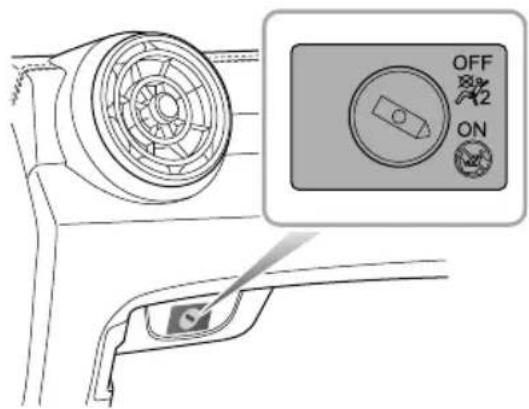
text_image
Diagram showing a car interior with a circular fan, a switch, and a directional control panel labeled OFF, ON, and 2.SEATS&RESTRAINTS
Thepassengerairbagdisableswitchislocatedinsideofthe glovebox,T odisablethepassengerairbag,insertthekey andturntheswitchtoOFFposition.
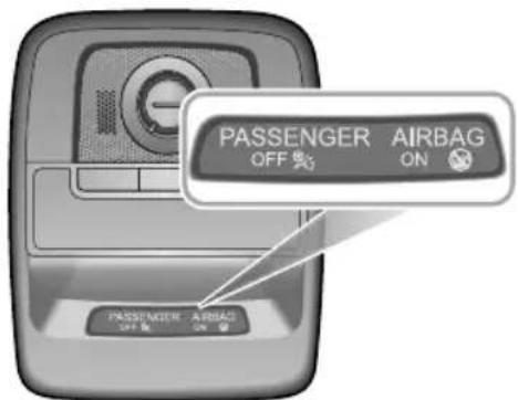
text_image
PASSENGER AIRBAG OFF ON PASSENGER AIRBAG OFF ONThepassengerairbagstatuslightislocatedintheroof mountedinteriorlampassembly.Theshapeofthelamp assemblyvariesaccordingtotheconfigurationofthe vehicle.
WhentheswitchisturnedtotheOFFposition,theOFF indicatorlight(locatedrthePABdisplaypanelrthdamp assembly)illuminates,thisindicatesthatthepassenger airbagisdisabled.
WhentheswitchisturnedtotheONposition,theON indicatorlight(locatedrthePABdisplaypanelrthdamp assembly)illuminates,thisindicatesthatthepassenger airbagisenabled.
ServiceandReplacementofAirbags
ServiceInformation

DONOTinstallormodifytheairbag.Any changestothevehiclestructureorairbag systemwiringharnessarestrictlyprohibited.

Changestovehiclestructureisprohibited. This may affect thenormaloperationofthe SRS.

DONOTallowthesearestobefloodedwith liquidandDONOTusepetrol,detergent, furniturecreamorpolishes.

IfwatercontaminatesorenterstheSRSit maycausedamageandaffectdeployment. InthiscasecontactanMGAuthorised Repairerimmediately.
T opreventdamagetotheairbagSRS, the following areasshouldbecleanedsparinglywithadampclothand upholsterycleanerONLY:
Steeringwheelcentrepad.
Areaofdashboardcontainingthepassengerairbag.
Areofodiningforpillafinisherwhich enclosethesideheadimpactprotectionmodules. Iftheairbagwarninglampfailstoilluminate,stayson,or ifthereisdamagetothefrontorsideofthevehicle,or theairbagcoversshowsignsofdamage,contactanMG AuthorisedRepairerimmediately.
IMPORTANT
Theremovalorreplacementofanairbagmodule shouldbecarriedbutbyanMGAuthorisedRepairer. After 10 years from the initial date of registration (or installation date of fareplacement airbag), some components will need to be replaced by an MG Authorised Repairer. The appropriate page of the Service Portfoliomust besigned and stamped once the work has been completed.
SEATS&RESTRAINTS
ReplacingAribagSystemParts

Eveniftheairbagdoesnotdeploy,collisions maycausedamagetoSRSinthevehicle. Airbagsmaynotfunctionproperlyafter damage,andcannotprotectyouandother passengerswhenasecondcollisionoccurs, whichmaycauseseriousinjuryoreven death.ToensurethatSRScanfunction properlyaftercollision,pleasegotoanMG AuthorisedRepairertocheckairbagsand repairasnecessary.
Airbagsaredesignedforusingonceonly.Oncetheairbag isdeployed,youmustreplaceSRSparts.
PleasegotoanMGAuthorisedRepairerforreplacement.
DisposalofAirbags
When your vehicle is sold, ensure that the new owner knows the vehicle is equipped with air bags, and is aware of thereplacement date of SRS.
If the vehicle is scrapped, the undeployed air bags may have potential risks, therefore, before the disposal, they must be deployed safely in a certain environment by a professional from MGA authorised Repairer.
ChildRestraints
ImportantSafetyInstructionsaboutUsing ChildRestraints
It is recommended that children below the age of 12 years old should be seated on there are seat of the vehicle, in a childrestraintsystem appropriateto the children's weight and size. Infants less than 2 years old should be restrained in an infant childrestraintsystem.
It is recommended that a child restraint system that complies with UNECE-R44 or ECE-R129 standard are fitted in this vehicle. Checkmarkings on the child restraint system.
Thereareanumberofchildrestraintsystemsavailableof differenttypeandspecification.Foroptimumprotection, itisrecommendedthatyouchooserestrainsystems appropriatetothechild'sageandweight.
It is important to comply with installation instructions supplied by the child restraint manufacturer and that child restraints system is properly secured to the vehicle. Failure to follow these instructions may cause death or serious injury to the child in an event of sudden stop or accident.
- Allooccupants, including children must wear seat belts or use an appropriate child restraint.
- It is recommended that children under 12 year sofage or less than 1.5 met restall should us the appropriate child restraint fitted to there are seat.
• Onlyonechildcanbecarriedinanyonerestraint. - Donotputthechildonthelaporinarmswhensitting inanyseat.
•Alwaysadjusttheseatbackresttoacentralposition andensureitislockedinpositionwheninstallingachild seatorrestraint. - Ifinstallingarearfacingchildrestrainttotherear seat, thecorrespondingfrontseatshouldbeadjusted forward; ifinstallingaforwardfacingchildrestraint totherearseat, youmayneedtoadjusttheheight oftheheadresttothelowest; ifinstallingaforward facingchildrestrainttothefrontseat, youmayneedto removeitsheadrest.
- Neverletyourchildstandorkneelontheseatduring driving.
•Alwaysensurethechilddisseatedcorrectlyinthechild restraint.
SEATS&RESTRAINTS
- Thewaysofusingseatbeltshaveagreatinfluenceon themaximumprotectionofferedbytheseatbelt,you mustcomplywiththechildrestraintmanufacturer's instructionsonproperuseofseatbelts.Ifseatbelts arenotproperlyfastened,aminortrafficaccidentmay alsoleadtoinjury.
- Childrestraintsthatarenotfittedcorrectlymaymove andinjureotheroccupantsintheeventofanaccident oemergencybraking. Therefore, evenifthereisno infantorchildinthechildrestraint, italsoshouldbe fittedproperlyandsecurelyinthevehicle.
WarningsandInstructionsonUseofChild RestraintonFrontPassengerSeat
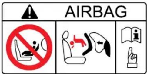
text_image
AIRBAG NO S S SWhen the front passenger air bag is active, never install are ar facing child restraint on the front passenger seat, severe injury overven death can occur.
Incaseswherethereisaneedtoinstallarear facingchildrestraintonthefrontpassenger seatsthkeydeactivatthfront passengerairbagfunction,orseverinjury orevendeathcanoccur.
Oncethechildrestraintisremovedfromthe frontpassengerseat, usethekeytoreactivate thefrontpassengerairbag.
Wheninstallingachildrestraintonthefront passengersatmovefrontpassenger seatasfarrearwardaspossible.
Useonechildrestraintperchild.
SEATS&RESTRAINTS
Pleasestudythesafetywarninglabelonthesunvisor. Wherepossiblealwaysinstallchildrestraintsontherear seat.Ifitisnecessarytoinstallachildrestraintonthefront seatpleaseobservethewarningsabove.
Children's Safety and Side Airbags

Childrenshouldnotbeallowedinareas whereairbagsmaybedeployed,thereisa riskofseriousinjury.

Only recommended child restraint suitable for the age, height and weight of the child should be used.

DONOTplaceanyitemsinareaswhere airbagsmaybedeployed,thereisariskof seriousinjury.
Intheeventofasidecollision,thesideairbagscanprovide betterprotectionforthepassenger .However,when theairbagistriggeredaverystrongexpansionforceis generated,ifthepassenger'sseatingpositionisnotcorrect,
theairbagsoritemsinthesideairbagdeploymentarea maycauseinjury.
Whenthecorrectchildrestraintisusedtosecurethe childproperlyintherearseatandthechild'sseating positioniscorrect,thereisenoughspacebetweenthe childandthesideairbagdeploymentregionfortheairbag todeploywithoutanyhindrance,andthusprovidethe bestprotection.
SEATS&RESTRAINTS
ChildRestraintsGroups
SecuredUsing3PointlapDiagonalBelts

Please DONOT put therear facing child restraint in the front passenger seat, this may cause serious injury overvendeath.
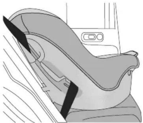
natural_image
Interior view of a car seatbelt device showing seat, seatbelt, and seat cover (no text or symbols)It is recommended that children should always be seated in therearofthe vehicle in a child restraint or restraint system, and fixed with 3 point, lap diagonal seat belts.
ISOFIXChildRestraintSystems

TheISOFIXanchoragesintherearseatare designedforusewithISOFIXsystemsonly.

Childrestraintanchoragesaredesigned towithstandonlythoseloadsimposed by correctlyfittedchildrestraints. Underno circumstancesaretheytobeusedforadult seatbelts,harnesses,orforattachingother itemsorequipmenttothevehicle.
Note: When installing and using any child restraint system, always follow the manufacturer's instructions.
Note: Therearseatsfittedtothisvehicleareprovided withtheISOFIXinterface(asindicatedbythearrowin thefollowingimage),thesearedesignedtoconnectto anISOFIXchildseat.
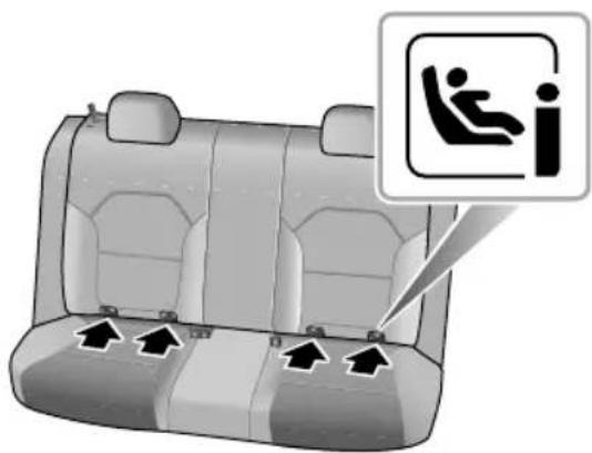
natural_image
Interior view of a car backseat with seatbelt and seatbelt switch icons (no text or symbols on the seats)- Fastenvehicle-approvedISOFIXchildrestraintsystems tothemountingbrackets.
- When using ISOFIX mounting brackets for seat mounting, universally approved child restraints systems for ISOFIX maybe used.
Note: When using seat mounting, universally approved childrestraintsystems, Top-tethermustbeused.
Note: Pleaserefertothechildrestraintsystem manufacturer'sinstructionsfordetails.
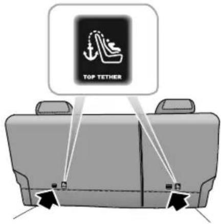
text_image
TOP TETHER•T ofastentheT optetherstrapofthechildrestraint system, routethetetherstrapundertheheadrestraint andattachtotheanchoragehookbeingcarefulnotto twistthestrapfnotusingISOFIXloweranchorages, usingtheseatbelt,completetheinstallationinlinewith thechildrestraintmanufacturesinstructions.
SEATS&RESTRAINTS
- After installation applysuitable for cetosure the restraint is securely fastened.
ApprovedChildRestraintPositions
It is recommended that a child restraints system that complies with UNECE-R44 or ECE-R129 standard are fitted in this vehicle. Checkmarkings on the child restraints system.
ApprovedChildRestraintPositions(fornonISOFIXChildRestraints)
| MassGroup | SeatingPositions | ||||
| FrontPassenger | Rear Outboard | Rear Middle | |||
| WithoutFront PassengerAirbag OFFSwitch | WithFrontPassengerAirbagOFFSwitch | ||||
| AirbagONAirbagOFF | |||||
| 0group(lessthan10kg) | XXXUX | ||||
| 0+group(lessthan13kg) | XXXUX | ||||
| Igroup(9~18kg) | XXUUX | ||||
| IIgroup(15~25kg) | UUUUX | ||||
| IIIgroup(22~36kg) | UUUUX | ||||
| Note:Descriptionoflettersinthetable:U=Suitableforuniversalchildrestraintsystemsapprovedforthismassgroup;X=Seatpositionnotsuitableforchildrestraintsystemsinthismassgroup. | |||||
SEATS&RESTRAINTS
ApprovedChildRestraintPositions(forISOFIXChildRestraints)
| SeatingPosition | Massgroupcategories | ||||
| 0group0+group | Igroup | ||||
| RearfacingForwardfacingRearfacing | |||||
| Upto29lbs(13kg)20–40lbs(9 ~ 18kg) | |||||
| FrontPassenger Seat | SizeClass | NotISOFIXequipped | |||
| SeatT ype | |||||
| RearOutboard SeatISOFIX | SizeClassC,D,E | ^1 | A,B,BI ^1 | C,D ^1 | |
| SeatT ype | IL ^2 | IL ^2 ,IUF ^3 | IL ^2 | ||
| RearCentreSeat | SizeClass | NotISOFIXequipped | |||
| SeatT ype | |||||
Note: ILSuitableforparticularISOFIXchildrestraintssystemsofthesemi-universalcategory.Pleaseconsultchildrestraints systemssuppliers'vehiclerecommendationlists;
IUSuitable for SOFIX forwarding hild restraintsystem of universal category approved using this mass group and ISOFIX size class;
^1 ThdSOFIXsizelassolbothuniversalandemi-universathildeasystemsidefinedbythecapitalettergradeA \~ G. TheseidentificationlettersaredisplayedonthelSOFIXchildseat;
^2 .AttimeofpublishingtherecommendedGroup0+ISOFIXbabysafetyseatistheBritaxRomerBabySafe.ConsultanMGAuthorisedRepairerforthelatestdetailsrelatingtoourrecommendedchildseats;
^3 .AttimeofpublishingtherecommendedGroupIIISOFIXchildseatistheBritaxRomerDuo.ConsultanMGAuthorised Repairerforthelatestdetailsrelatingtoourrecommendedchildseats.
Note:AttimeofpublishingtherecommendedGroupII-IIIISOFIXchildseatistheKidFixXP .ConsultanMGAuthorised Repairerforthelatestdetailsrelatingtoourrecommendedchildseats.
T ableofl-Sizechildseats
Thetablegivesarecommendationforwhichl-Sizechildseatssuitwhichlocations,andforwhatsizeofchild.
ThechildseatmustbeapprovedinaccordancewithUNRegRI29.
| T ypeofchildseat | FrontpassengerseatRearoutboardseatsRearcentreseat | |
| I-Sizechildrestraintsystems | XI-UX |
Note: I-USuitableforusewithforwardandrearfacingl-Sizechildrestraintsystems.
XNotsuitableforusewithl-Sizerestraintsystems.
SEATS&RESTRAINTS
Group0/0+ChildRestraint

Whenthefrontpassengerairbagisactive, neverplacearearfacingchildrestraint on thefrontpassengerseat,severeinjuryoreven deathcanoccur.
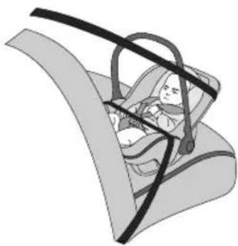
natural_image
Illustration of a baby car seatbelt in a compact car seat (no text or symbols)Childrestraintsthatcanbeadjustedtolyingposition aremostsuitableforinfantswhoarelighterthan10kg (normallyforthoseyoungerthan9months)orthosewho arelighterthan13kg(normallyforthoseyoungerthan24 months).
Group|ChildRestraint

Whenthefrontpassengerairbagisactive, neverplacearearfacingchildrestraint on thefrontpassengerseat,severeinjuryoreven deathcanoccur.
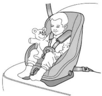
natural_image
Illustration of a child in a baby car seat with a teddy bear, no text or symbols presentBackward/forwardchildrestraintsaremostsuitablefor infantswhoseweightis9 \~ 18kg(normallyforthoseolder than9monthsandyoungerthan4yearsold).
SEATS&RESTRAINTS
GroupIIChildRestraint

Thediagonalsectionoftheseatbeltshould passacrosstheshoulderandupperbody, awayfromtheneck. Thelapsectionofthe beltshouldpassacrossthehips,awayfrom theabdomen.
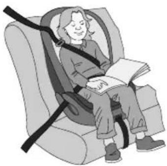
natural_image
Illustration of a person sitting in a car seat using a seatbelt, holding an open book (no text or symbols visible)The combination of child restraint and 3 point lap diagonal seat beltismost suitable for children whose weight is 15 \~ 25 kg (normally forthose older than 3 years old and younger than 7 years old).
GroupIIChildRestraint

Thediagonalsectionoftheseatbeltshould passacrosstheshoulderandupperbody, awayfromtheneck. Thelapsectionofthe beltshouldpassacrossthehips,awayfrom theabdomen.
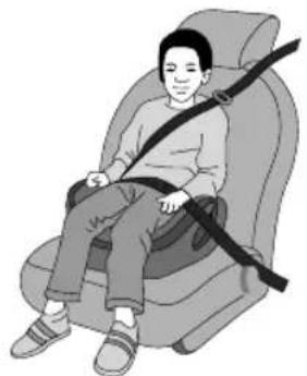
natural_image
Illustration of a person sitting in a car seat with a belt (no text or symbols)The combination of child booster seat and vehicle 3 point lap diagonal seat belt is most suitable for children whose weight is 22 \~ 36 kg and whose height is below 1.5 m (normally forthose about 7 years old to those older than 7 years old).
Starting&Driving
146Keys
151 ChildProofLocks
152AlarmSystem
159StartingandStoppingEngine
167EconomicalandEnvironmentalDriving
170 CatalyticConverterandParticulate Filter
I72FuelSystem
I 74AutomaticTransmission *
181 ManualTransmission *
184BrakeSystem
197AutomatedStop/Start—Intelligent FuelSavingSystem
202StabilityControlSystem(SCS)and TractionControlSystem(TCS)
204 CruiseControlSystem
207ActiveSpeedLimit(ASL)System
210ParkingAidSystem
214 RearDriverAssistanceSystem
220TyrePressureMonitoringSystem (TPMS)
222LoadCarrying
STARTING&DRIVING
Keys
Overview

Keepthesparekeyinasafeplace-notinthe vehicle!

Itisrecommendedthatsparekeysarenot keptonthesamekeyring, sincethismay causeinterferenceandpreventcorrectkey recognitionandthereforepreventtheengine fromstarting.

Thekeycontainsdelicateelectronic componentsandmustbeprotectedfrom impactandwaterdamage,hightemperature andhumidity,directsunlightandtheeffects ofsolvents,waxesandabrasivecleaners.
Differentkeykitsareprovidedaccordingtovehicle configurations. Onekitincludestwosmartkeys;andthe othekincludestwoemotkeyTheyappeall locks.
Thekeyssuppliedtoyouhavebeenprogrammedfor thesecuritysystemonyourvehicle.Anykeythatisnot programmedtoyourvehiclecannotstarttheengine.
The key only work with in certain range. Its operating range is sometimes influenced by the key battery condition, physical and geographical factors. Forsafety consideration, after you lock your vehicle by the key, pleasere check if the vehicle is locked.
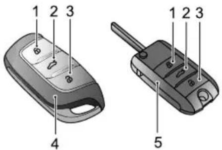
text_image
1 2 3 4 1 2 3 5Lbckbutton
T2 ailgatereleasebutton
Unlockbutton
4Smartkey
5Remotekey
Ifyourkeyislost/stolenorbroken,areplacementcanbe obtainedfromanMGAuthorisedRepairer. Thelost/stolen keycanbedeactivated. Ifthelostkeyisfound,anMG AuthorisedRepairercanreactivateit.
Note: AnykeymadeindependentlyoutsideofMG AuthorisedRepairerNetworkmaynotstartthe engine, and may affect the safety of your car. To obtain suitable key replacement, it is recommended that you can consult MGAuthorisedRepairer.
Notrenewkeycannotbeofferedtoyou immediatelybecauseitrequiresprogrammingtothe vehiclebytheMGAuthorisedRepairer.
Note: When operating your vehicle with the smart key, avoid placing it near the devices with a strong radio interference (such as notebook computers and other electronic products), then normal function of the key may be affected.
ReplacingtheBattery
Pleaseusethepictureguidetoreplacethekeybatteryif anyofthefollowingconditionsoccur:
•Thekeylocking/unlockingfunctionrangeisreduced;
•Theengineimmobilisationwarninglamponthe instrumentpackflashes(Referto"WarningLightsand Indicators"in"InstrumentsandControls"section).
SmartKey *
A
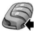
B
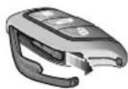
C
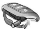
D
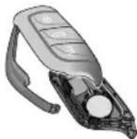
STARTING&DRIVING
I Pressthebutton(A)onthesmartkeytoejectthe decorativetrim.
2Removethebackupmechanicalkey(B)inthearrowed direction.
3Usingasuitableflatbladedtool,insertthetoolinto thesideofthekey(C),carefullypriseoffthebattery coverandseparatetheupperandlowercasings(D).
4Removethebatteryfromtheslot.
5Putthenewbatteryintheslot, and makesureitisin fullcontactwiththeslot.
Note: Makesurethatthepolarityofbatteryis correct('+'sidefacingdown).
Note: It is recommended to use a CR2032 battery.
6Refitthecoverandpresstightly,ensuringthegap aroundthecoveriseven.
7Refitthemechanicalkey, andclosethedecorativetrim.
8Starttheenginetoresynchronisethekeywiththe vehicle.
Remotekey *
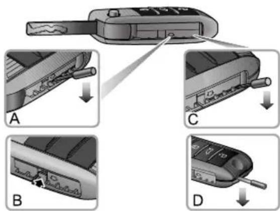
text_image
Diagram illustrating four steps of a car key being inserted into a device, labeled A, B, C, and D.STARTING&DRIVING
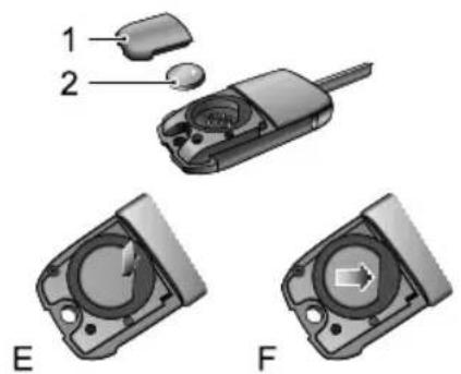
text_image
1 2 E FI Unfoldtheremotekey.
2Withaflat-bladedtool,insertitbelowthearrowmark atthesideofthekey(A),andpryupthebatterycover carefullyuntilthelockpinsareseparated(B).
3Theninserttheflat-bladedtoolintotheillustrated position(C),andapplypressureinthedirection indicatedbythearrowuntilthetailofthekeymakes agap.
4Continuetousetheflat-bladedtoolinsertingitinto theendofthekey/batterycover(D),slightlyprythe batterycoveruntilthetwobayonetsattheendof batterycoverarereleased.
5Carefullypriseoffthebatterycover(I).
6Pressthefrontpartofbuttonbatteryusingslightforce (E)toremovethebattery(2).
7Positionthenewbattery, ensuring that correct polarity is maintained ("+" sidefacingup), slideitforward(F) ensuring it is fully inserted into the slot.
Note: Makesurethepolarity is correct (positive sideupward).
Note: It is recommended to set the R2032 replacement battery.
8Refitthecoverandpresstightly,checkthegaparound thecoveriseven.
Isettemokerygniticswitdo resynchroniseit.
STARTING&DRIVING
IMPORTANT
- Useofanincorrectorinappropriatebatterymay damagethekey. Thenewreplacement'srated voltage, sizesandspecificationsmustbethesame astheoldone.
- Incorrectfittingofthebatterymaydamagethekey.
- Disposaloftheusedbatterymustbestrictlyin accordancewithrelevantenvironmentalprotection acts.
STARTING&DRIVING
ChildProofLocks

NEVERleavechildrenunsupervisedinthe vehicle.
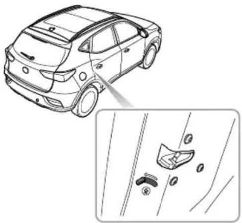
natural_image
Line drawing of a car with a magnified inset showing a close-up of the side panel (no text or symbols)Stepsforenablingordisablingthechildprooflocksareas follows:
- Openthereardooratcorrespondingside,move thechildprooflocklevertothelockpositioninthe directionofthearrowtoengagethechildprooflock; - Movethelevertotheunlockpositioninthereverse directionofthearrowtodisablethechildprooflock. Withthechildprooflocklocked,thereardooratthe correspondingsidecannotbeopenedfrominsidethecar, butcanbeopenedfromoutsidethecar .
STARTING&DRIVING
AlarmSystem
Y ourcarisfittedwithananti-theftalarmandengine immobilisationsystem.T oensuremaximumsafetyand operationconvenience,westronglyrecommendyouto carefullyreadthischaptertofullyunderstandtheactivation anddeactivationofanti-theftsystems.
tool, insert the tool into the underside of the trim and carefully removed the driver door lock trim cover, insert the key into the driver door lock and turn clockwise tounlock the car.
Note: If the START/STOP switch is not placed in ACC or ON/RUNNING position within 15 seconds after the vehicle is unlocked with the mechanical key, the engine immobilisation alarm will be triggered.
Note: If nonpanels are opened within 30 seconds after the vehicle unlocked by using the emotkey all doors will automatically re-lock.
OperationofDoorLockSystem(Keyless)
Thekeylessentrysystemcanlockandunlockthedoors andtailgateaslongasyoucarrythesmartkeyandapproach tothecar.
IMPORTANT
Thesmartkeymustbewithin 1.5metresofthevehicle forthekeylesssystemtooperatecorrectly.
STARTING&DRIVING
KeylessLocking
AfterswitchingtheSTART/STOPSwitchtoOFFposition andexitingthecar,pressthedoorhandlebuttononce beforemovingawayfromthecartolockalldoorsand tailgate(noneedtopressthelockbuttononthekey). Note,thiswillalsoarmthealarmandimmobilisethe vehicle.
KeylessUnlocking
Pressthebuttononthefrontdoorhandleoncetounlock thecar,thenpullthedoorhandletoopenthedoor.
Note: Whenthevehicleislocked, if you are within the smart key range and operate the door handle button, but carry out no further action, after 30 seconds the vehicle will automatically re-lock itself to remain secure.
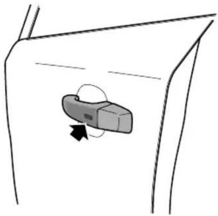
natural_image
Simple line drawing of a door handle with a button and arrow indicating direction (no text or symbols)IMPORTANT
Afterthedoorislockedbyusingthekey,pressthe buttononthedoorhandletounlockthecar.Ifthecar cannotbeunlockedorlockednormally,seekanMG AuthorisedRepairer.
STARTING&DRIVING
Mislock
Ifthedriver'sdoorisnotfullyclosedwhenthesmartkey lockbuttonispressed,ortheSTART/STOPSwitchhas notbeenswitchedOFF ,thevehiclehornwillsoundonce, indicatingamislock.Inthiscase,noneofthedoorswill lock,thealarmsystemwillnotbearmed.
Ifthedriver'sdoorisclosed,thepassengerdoor,bonnet andtailgatearenotfullyclosed,thehornsoundsonceto indicatemislockwhenthecarundergoeslockingoperation. However ,the'partialarming'attributesofthesecurity systemwillenableasmuchofthesystemtobearmedas possible(allfullycloseddoors,bonnetortailgateapertures willbeprotected,butanopendoorwillnot!).Thealarm indicatorwillflash.Assoonastheopenapertureisclosed, thesystemwillautomaticallyreverttoanarmedstate
InadvertentLockingofKeysinVehicle \*
If the vehicle is locked using the mechanical key blade or handset whilst a smart key/s remain inside, the following actions will occur:
- Onesmartkeylockedinthevehicle-The immobilisationreleasefunctionofthesmartkeylocked
inthevehicleissuspended, thelock and unlock function of thesmart key is retained. The engine cannot be started. T oreinstatetheimmobiliserrelease function of thesmart key locked in the vehicle these second smart key should be used to unlock the vehicle. The function will automatically bereinstated.
- Bothsmartkeyslockedinvehicle-Theimmobilisation releasefunctionofbothsmartkeyslockedinthevehicle issuspended,thelockandunlockfunctionofthesmart keysisretained.Theenginecannotbestarted.The reinstatementofkeyfunctionscanonlybecarriedout usingtheapproveddiagnostictool.ConsultanMG AuthorisedRepairerimmediately.
Anti-theftAlarmSounder
If the anti-theft alarm has been triggered, the car horn will sound continuously. Press the UNLOCK button on the key, the anti-theft alarm will be deactivated.
STARTING&DRIVING
InteriorLockandUnlockSwitch
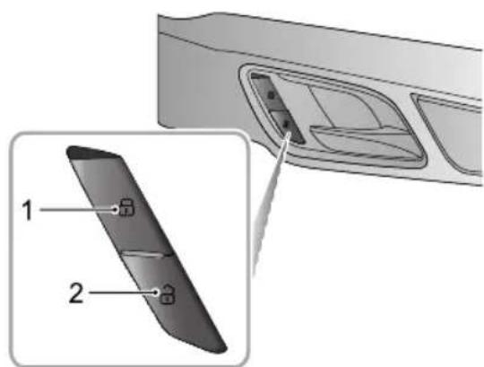
text_image
Diagram showing a device's internal structure with labeled parts 1, 2, and 3, including an inset view of the component.ILockSwitch
2UnlockSwitch
Whentheanti-theftalarmsystemisnotinoperation,press thelockswitch(1)tolockalldoors;presstheunlock switch(2)tounlockalldoors.
Note: If the anti-theftalarmsystem is switched on, pressing the lock/unlock button will not lock/unlock the doors but will trigger the alarms system.
Ifthedoors, bonnetandtailgateareclosed, pressthe interiorlockswitch. They yellowindicatorontheinterior lockswitchilluminates.
Ifamislockiscausedbynon-driverdoor,tailgateorbonnet, presstheinteriorlockswitch.Theyellowindicatoronthe interiorlockswitchilluminates.
InteriorDoorHandles
Whentheanti-theftalarmsystemisnotinoperation,use theinteriordoorhandletoopenthedoor:
I Pulltheinteriordoorhandleoncetounlockthedoor.
2Pulltheinteriordoorhandleagaintoopenthedoor.
SpeedLock
Allthedoorswillbelockedautomaticallywhentheroad speedexceeds 10mph(15km/h).
AutomaticUnlock
When the START/STOP switch is switched to the OFF position, all the doors will be unlocked automatically.
T ailgate

Ifthetailgatecannotbecloseddueto thetypeofcargoloaded,besuretoclose allwindowsduringdriving,selecttheface distributionmodeoftheaircondition,and settheblowertomaximumspeed,soasto decreaseexhaustfumesenteringthevehicle.
T ailgateOpenMode
Thetailgatecanbeopenedbyusingthefollowing2 methods:
- Whenthevehicleisunlockedorthematchedkey appearswithin Imrangearoundthetailgate, directly openthetailgatebyturningovertheemblemonthe tailgate(FigureA).
- When START/STOPSwitchintheOFFposition, press thereleasebuttonontheremotekey(FigureB) for more than 2 second stoopenthetailgate.
STARTING&DRIVING
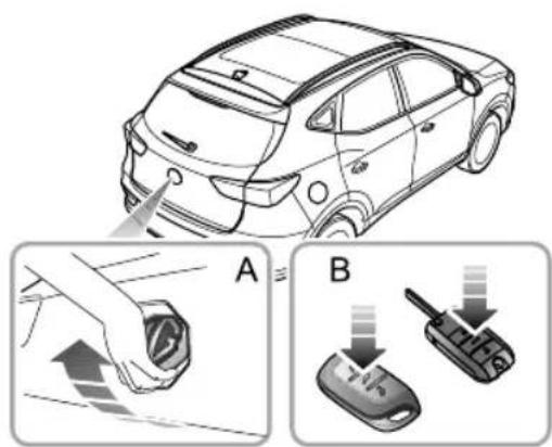
text_image
Diagram illustrating car battery charging process with labeled steps A and B showing hand insertion and disassembly of a key.EmergencyT ailgateOpening
The emergency tailgaterelease access is located in the centre of the tailgatetrim.
Folddowntherearseattogainaccess,removethe blankingplug,androtatetheemergencyopenknob counterclockwisetoopenthetailgatefrominside.
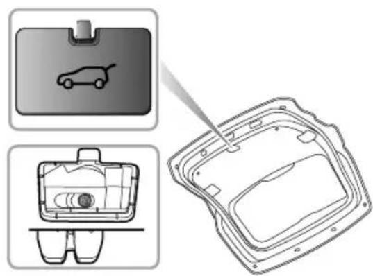
natural_image
Technical line drawing of a car interior frame with two views: top shows a car icon, bottom shows a device outline (no text or symbols)STARTING&DRIVING
StartingandStoppingEngine
IgnitionSwitch ((KeyStart))*)

Whenthevehicleisinmotion,DONOT switchofftheignitionorremovethekey, otherwisethesteeringwheelmaybelocked, makingitimpossibletoturnthevehicle.

Whenthevehicleisinmotion, DONOT touchthekeytoavoidengineflameout!
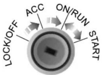
text_image
LOCK/OFF ACC ON/RUN STARTTheignitionswitchislocatedontherightsideofthe steeringcolumn.Functionofeachpositionisasfollows:
PositionLOCK/OFF
•Thekeycanbeinsertedorremoved.
• After the engine is stopped and the key is removed, turn the steering wheel to onesidetolock the steering wheel.
PositionACC
• The engine is not started and the key cannot be removed.
- Someindividualelectricalequipmentandaccessories canbeoperated,suchaspowerwindows.
PositionON/RUNNING
•Allelectricalequipmentisoperational.
•Afterthevehicleisstarted,theengineeruns.
PositionSTART
•Enginewillrunafterstarting.
Releasdimmediately after engine started heignitionswitchwillreturntoposition ON/RUNNINGautomatically.
STARTING&DRIVING
- Whentheengineisstarting, someelectricalequipment will be isolated during cranking.
Note: The key can only be turned from ACC position to LOCK/OFF position when the shift lever is in P (parking) position.
Note: WhentheignitionswitchisintheOFFposition, ifthedriversidedoorisopened,anaudiblewarning soundstoindicatethatthekeyhasnotbeenremoved.
Note: Whenthesteeringwheelislockedandthekey cannotbeturnedfromtheOFFpositiontotheACC position, pleaseturnthesteeringwheelslightlywhilst turningthekeytounlockthesteeringwheel.
START/STOPSwitch(KeylessStart) \*
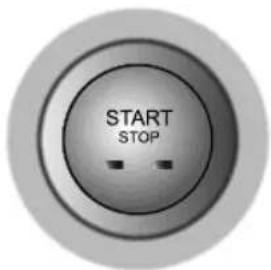
text_image
START STOPThekeylessST ART/STOPSwitchislocatedinthefasciato theleftofthesteeringcolumn,itisapushbuttonstyle switch.
Note: cooperatethesystem, theremotekeymust beinthecdroremovethegearleverfromthe ParkpositiontheSTART/STOPSwitchmustbein ON/RUNNINGposition,andthebrakepedalmustbe depressed.
STARTING&DRIVING
Theoperationalstatusdisplaysareasfollows:
IndicatorOff(OFF)
•Theengineisshutoffinthisposition.
- Someelectricalequipmentcanbeoperated,suchas powerwindows.
- PressingtheSTART/STOPSwitchwithoutthefootbrake beingappliedwhilsttheengineisOFFwillplacethe systemintheACCstate,thiswillilluminatetheyellow indicatorintheswitchbutton.
YellowLight(ACC)
GreenLight(ON/RUNNING)
•Allelectricalequipmentisoperational.
- Driveandstartthevehicle.
- WhilstintheACCstate,pressingtheSTART/STOP Switchwithoutthefootbrakebeingappliedwillplace thesystemintheONstate,thegreenindicatorwill illuminate.
Note: After turning the START/STOP switch to the OFF position and opening the door, if the key is still left in the vehicle, the audible warning will sound when
closingthedoor,toremindyouthatthekeyisstillin thevehicle.
If your carissubjecttostrongradiosignalsthekeyless entry and start systemsmaysuffer from interference and not function correctly. Please seethe 'Alternative Starting Procedure'.
STARTING&DRIVING
StartingtheEngine ( ( KeyStart )) \* )

Neverstartorleavetheengine running in anunventilated building. Exhaust gases are poisonous and contain carbon monoxide, which can cause unconsciousness and may even be fatal.

Catalyticconvertersandparticulatefilters can bedamaged if the wrong fuel is used, or if an engine misfire occurs. Before starting the engine, pleaseread carefully the contents in the "Catalyticconverter and Particulate Filter" section.
OperationofStartingtheEngine
Switchless electricity equipment (including the air conditioning);
2Applytheparkingbrake(referto"BrakeSystem" of thissection);
3Forautotransmissionvehicles,ensuretheshiftlever isinPorNposition;
Note: Whentheshiftleverisinanyotherposition, theenginecannotbestarted.
Famanuataransmissionehiclensureeutral selectedandtheclutchpedalisfullypressed;
5Insertthekey, rotateittoposition STARTandrelease thekeyimmediatelyaftertheengineisstarted.
Note: After the engine starts, if the key is not released immediately, the starter will continuetowork, which will not only discharge the battery, but also damage the starter and starter motor, catalytic converter and particulate filter.
STARTING&DRIVING
StartingtheEngine (( KeylessStart )) \*)
StartingtheEngine:
I Switchoffallunnecessaryelectricalequipment (includingtheairconditioning);
2Applytheparkingbrake(referto"BrakeSystem" of thissection);
3Forautotransmissionvehicles, EnsurePorNis selectedandpressthebrakepedal.
4Formanualtransmissionvehicles,ensureneutralis selectedandtheclutchpedalisfullypressed.
5PresstheSTART/STOPSwitch(donotholdthebutton in, releaseimmediately).
AlternativeStarRingcedure ( ( ( Auto Transmission) )
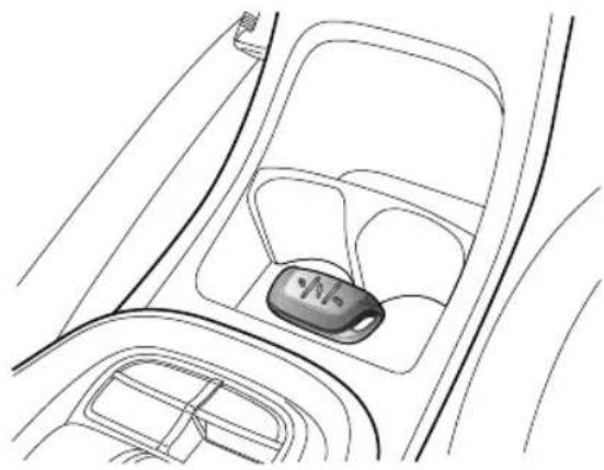
natural_image
Line drawing of a car interior showing the dashboard and seat area (no text or symbols)Ifthecarislocatedinanareawheretherearestrong radiosignalscausinginterferenceorthesmartkeybattery conditionislow,pleaseusethefollowingstepstoattempt tostartthecar:
I Forvehicleswithcupholder,removethecupholder.
STARTING&DRIVING
2Placethesmartkeycentrallyinthecentreconsolecup holdercubbyboxwiththebuttonsfacingupward-as shownintheillustration.
3EnsurePorNisselected, pressthebrakepedaland thenpressST ART/STOPSwitchtostartthevehicle.
Iftheimmobilisercannotbereleasedafterthecarhasleft theareaofstrongradiointerferenceorhadthesmart keybatteryreplacedpleaseconsultanMGAuthorised Repairer.
AlternativeStartingProcedure ( ( ( Manual T transmission ) )
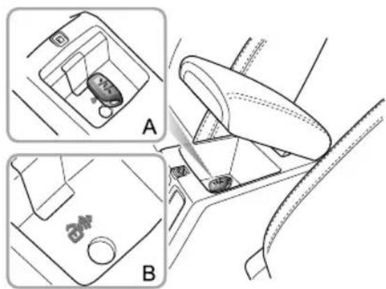
natural_image
Diagram of car gear shift lever and seatbelt mechanism (no text or symbols)Ifthecarislocatedinanareawheretherearestrong radiosignalscausinginterferenceorthesmartkeybattery conditionislow,pleaseusethefollowingstepstoattempt tostartthecar:
I Placethesmartkeycentrallyinthecentreconsolecup holdercubbyboxwiththebuttonsfacingupward-as shownintheillustration.
2PresstheclutchpedalandpressSTART/STOPSwitch tostartthevehicle.
Iftheimmobilisercannotbereleasedafterthecarhasleft theareaofstrongradiointerferenceorhadthesmart keybatteryreplacedpleaseconsultanMGAuthorised Repairer.
PrecautionsforStartingtheEngine
Idlespeedwilldecreaseafterenginewarm-up.Donot increaseenginespeedimmediatelyafterenginestarts. Progressivelyoperatetheengineandtransmissionsothat oilcanpreheatandlubricatealloperatingcomponents.
DONOTpresstheacceleratorpedalwhilestartingand DONOToperatethestarterformorethan15secondsat atime.
Intemperaturesof-10°Candbelow,enginecrankingtimes willincrease.Itisessentialthatallunnecessaryelectrical equipmentisswitchedoffwhilecranking.
IMPORTANT
•IfthevehiclewillnotenteraON/RUNNINGstate, pleasecheckforanywarningindicatorsormessages displayedintheinstrumentpackmessagecentre.In extremelylowtemperaturespleaseallow5minutes betweenstartingattempts,ifafter3attemptsthe vehiclewillnotstartpleaseconsultanMGAuthorised Repairerorbreakdownservice.
•DONOTleavetheignitionswitchintheACC, ON/RUNNINGorSTARTpositionsforanylengthof timewhentheengineisnotrunning,otherwiseitmay leadtobatterydischargeduetotheuseofelectrical equipments.
•Thevehicleisfittedwithengineimmobilisationsystem. Anyindependentlymadekeycannotstarttheengine.
- Yourcariscontrolledbyelectroniccontrolsystems. Whenstartingtheengine, pleasemakesurethereare noelectronicdevicesthatcancreateelectromagnetic interferencenearthevehicle. Thismaycauseissues withtheelectroniccontrolsystemsonthevehicle.
STARTING&DRIVING
StoppingtheEngine
Stoptheengineasfollows:
I Afterbringingthecartostop,continuetoapplythe footbrakeuntiltheparkingbrakeisapplied;
2Applyparkingbrake;
3Forvehicleswithautomatictransmission,ensurethat theshiftleverisinPposition.
4Forvehicleswithmanualtransmission,ensurethatthe shiftleverisinneutralposition.
5Forvehicleswithkeystart, turnthekeyfrom ON/RUNNINGpositiontoLOCK/OFFposition,the enginewillbeshutdownandthekeycanberemoved.
6Forvehicleswithkeylessstart, pressSTART/STOP Switchtoshutdowntheengine.
Note: For vehicles with key less start, when the engine need to be stopped in emergency, please press START/STOP switch and hold for more than 4 seconds to stop the engine.
Not afstrenuoutowingrivingtigh
speed(particularlyhoweather) suggested toallowtheenginetoidleforafewminutesbefore switchingffhichnabletheoolingstento workcontinuouslytolowertheenginetemperature.
EconomicalandEnvironmentalDriving
Running-in
Theengine, transmission, brakesandtyresneedtimeto
'bed-in' and adjust to the demand so every day motoring.
During the first 900 miles, please heed the following advice soastoenhancethelong-term operation performance:
- Donotallowtheenginetoexceed3000rpminanygear orthevehiclespeedtoexceed72MPH.
- Donotoperateatfullthrottleorallowtheengineto labourinanygear.
- Donotdriveataconstantspeed(eitherhighspeedor lowspeed).
- Avoidheavybrakingwherepossible.
After900miles, enginespeedscanbegraduallyincreased.
EnvironmentProtection
Y ourvehiclehasbeendesignedwiththelatesttechnology inordertominimizetheenvironmentalimpactofexhaust emissions.
EconomicDrivingandMaintenance
The following a resomes suggestions on saving fuel and extending the life of the vehicles.
- Maintain the correctty repressures; insufficient air pressure will accelerate teryrewear and wasteful.
- Donotcarryunnecessaryweightavyloads with creasehenginloads resulting high fuel consumption.
- Avoidengineidlingforextendedperiods.
- Maintainslowandsmoothaccelerationandavoidharsh acceleration;changetoahighergearassoonaspossible.
- Avoidlabouringtheengineoroverrunning.Choose appropriategearsaccordingtotheroadconditions.
- Avoidcontinuousaccelerationdeceleration. stop-godrivingstylewillconsumemorefuel.
- Avoidunnecessarystoppingandbrakingmaintain steadyspeedandattempttoanticipatetrafficlights.
Not Keep inappropriate distance from other vehicle to avoid emergency braking and reduce brake pad wear.
STARTING&DRIVING
- Avoidtrafficcongestionandjamareasasmuchas possible.
- Anticipatingobstructionsandslowingdownwellin advance,avoidstheneedforunnecessaryacceleration andharshbraking.Asmoothdrivingstylenotonly reducesfuelconsumption,butcanreducetheemission ofnoxiousgases.
- Donotridethebrakepedal, this can cause premature wear, overheating and increased fuel consumption.
- Maintainanappropriatespeedonthehighway.Higher speedsusemorefuel.Appropriatespeedscansavefuel.
- Maintain the correct wheel alignment. Avoid collision with the kerband reduces speed on uneven road surfaces. Out of specification wheel alignment will not only lead to excessivity to rewear, but also increase the engine load and fuel consumption.
- Avoiddrivingonmudorbeaches. This will prevent corrosion of the vehicle underside.
MaintawheheordansethG
recommendations.Dirtyairfilters,oiletc.,willreduce theengine'sperformanceandraisefuelconsumption.
Note: extend the life of all components and reducing operating costs, guided approved maintenance is needed.
- Donotstoptheenginestraightafterhighspeedorlong ascentsortowingatrailer.Allowtheenginetoidlefor 20to100secondsdependingupondrivingloadsand conditions.Avoidhardaccelerationonacoldengine.
DrivinginSpecialEnvironment
DrivinginRainorSnow

Emergencybraking, accelerating and steering onslipperyroadswillreducethevehicle's handlingperformanceandgrip.
- Whenrainingthewindowsmayfog, reducingvisibility (UsetheAir-conditioningdemistfunction).
- Gripwillbereducedwhenitrains,sopleasereduce speeddrivecarefully.
- Reducespeedwhenitrains.
- Avoid aquaplaning (the effect of a film of water between the tyres and theroad) affecting steering and braking performance.
DrivingthroughWater
Avoiddrivingthroughfloodsafterheavyrain,thismaylead toseriousdamagetothevehicle.
STARTING&DRIVING
CatalyticConverterandParticulate Filter

Thetemperaturesofexhaustsystemsthat containparticulatefiltersandcatalytic converterscanbeextremelyhigh,DONOT parkongroundwherecombustiblematerials suchasdrygrassorleavescouldcomeinto contactwiththeexhaustsystem-indry weatherafirecouldresult.
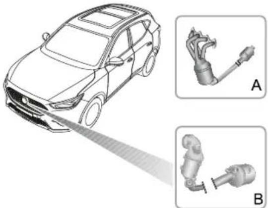
natural_image
Illustration of a car with a laser beam interacting with two mechanical components labeled A and B (no text or symbols present)Theexhaustsystemincorporatesacatalyticconverter andparticulatefilter(modeldependant),theseprocess possibleharmfulexhaustemissionsfromtheengineinto moreenvironmentallyfriendlygases.Exhaustsystem layoutsdifferbetweenenginederivatives.The1.5Lexhaust features(A).The1.0Texhausfeatures(B).
Catalytic converters particular filter easily damaged through improper use, especially if the wrong fue point incorrect specification used.
Fuel
Useonlyfuerecommendedforyourcar.
Neverallowthecartorunoutoffuel—thiscould causes serious damage to the catalytic converter and particulate filter.
EngineOils
recommendethanbythatateche
manufacturerspecificationareused.Useofoilsthat dooneebanufacturespecificationsan damageheparticulatefilterforexampleowSAPSoils canaffectparticulatefilterashcapacity.
STARTING&DRIVING
Starting
- Donotcontinuetooperatethestarterafterafewfailed attempts;seekanMGAuthorisedRepairer.
- Donotoperatethestarterifanenginemisfireis suspectedanddonotattempttoclearamisfireby pressingtheacceleratorpedal.
- Donotattempttopushortowstartthecar.
Regeneration
- Onoccasiontheparticulatefiltermayrequire regeneration.Y ourvehiclewillautomaticallycarry outthisprocedurewhencertainconditionsaremet. Duringthisprocessyoumayexperienceslightpower lossandunevenenginerunning.
Driving
Please pay attention to the following conditions:
- Donotoverloadorexcessively'rev'ofengine.
- Donotstoptheenginewhenthecarisinmotionwith agearselected.
- SeekanMGAuthorisedRepairerifyouthinkyourcar's oilconsumptionisabnormal.
•lfamisfireissuspected,orthecarlackspowerwhile driving,providedtheenginehasreachedtnormal operatingtemperature,itmaybedrivenSLOWLY(at riskofcatalystandparticulatefilterdamage)toanMG AuthorisedRepairer.
- Donotdriveonterrainlikelytosubjecttheunderside ofthecartoheavyimpacts.
Note: Anyenginemisfire, lossofengineperformance orenginerun-on, could seriously damagethecatalytic converterandparticulatefilter. Regularmaintenance must be carried out in accordance with the schedule specified in the 'ServicePortfolio' Anymodifications to enginewithoutbeingauthorisedisprohibited.
STARTING&DRIVING
FuelSystem
FuelRequirements

Useonlytherecommendedfuelwhich meetsnationalstandard!Seriousdamage tothecatalyticconverter,areductionin enginepower/torqueandincreaseinfuel consumptionwilloccurifthewrongfuelis used.
Pleaseusethefuelwhichisrecommendedandcertified bythemanufacturer.See'MajorParametersofEngine'in 'TechnicalData'.
Ifalowergradeoffuelisused,anengineknockingnoise mayoccur,pleaseusetherecommendedorabovegrade fuelassoonaspossible.Iftheengineknockingnoiseisstill noticeableafterusingtherecommendedorabovegrade fuel,pleasecontactMGAuthorisedRepairerimmediately.
SafetyPrecautionsinaFuelFillingStation

Vehicle has high flammable and, inconfined spaces, are also extremely explosive.
Alwaystakecarewhenrefueling:
Switchofftheengine.
Donotsmokeoruseanakedflame.
Donotuseamobilephone.
Avoidspillingfuel.
Donotoverfillthetank.
FuelFiller
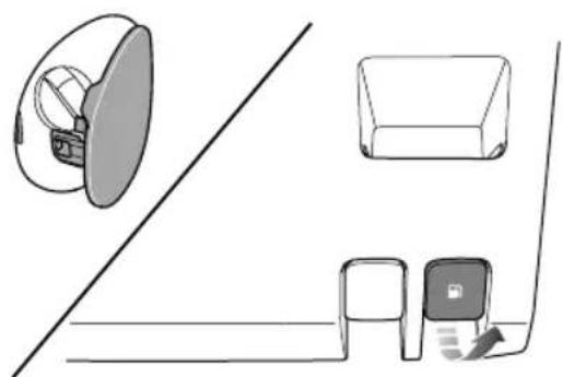
natural_image
Diagram showing three basic 3D object arrangements: a circular device, a rectangular box, and a printer with a scroll (no text or symbols)FuelFillerFlap
Thefuelfillerflapislocatedontherearright-handwing. Pullthefuelfillerflapreleasehandleunderthedriverside instrumentpacktoopentheflap.
FuelFillerCap
Unscrewthefillercapanti-clockwiseandallowany pressureinsidethetanktoescape,beforeeremovingthe cap.
Afterrefueling,tightenthefillercapclockwiseuntilyou hearone"click"sound.
Refueling
Donotfullyfillthetankifthevehicleistobeparkedin directsunlight,orhighambienttemperature-expansionof thefuelcouldcausespillage.Thefuelfillertubeisdesigned toacceptanarrow,longfillernozzle.Thereisacover atthefillerneck,byinsertingthefillernozzlethoroughly beforefuelfilling,thecovercanbefullyopened.
Starttheengineafterfuelfilling.Afterrefueling,if theengine runsunevenly,switchoffandseekanMG Authorised Repairer beforeattempting to start the engine.
STARTING&DRIVING
AutomaticT transmission\*
Instructions
The following information is very important, pleaseread carefully before use.
- Beforestartingtheengine, placethegearleverinPor Nposition, ensure the footbrake is pressed and the parkingbrake is applied.
• After the engine has started, ensure the footbrake and parking brake are applied, shift the lever to there required gear. - Releasetheparkingbrakeandholdthefootbrake untilyouarereadytomanoeuvrethevehicle.Once thefootbrakeisreleased,onflatroad,thevehicle willautomaticallystartoffataslowspeedwithout applicationoftheaccelerator.
- DonotmovethegearshiftleverintoPorRfrom Dwhilstdriving, this will cause severetransmission damage or cause an accident.
• T oremovethegearleverfromtheParkposition,the vehiclemusthavebatterypowerandtheSTART/STOP SwitchmustbeinON/RUNNINGposition.
GearShift
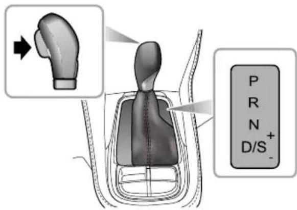
text_image
P R N D/S+ -Theautomatictransmissionisa6speedtransmission.
Note: The highlighted letters or numbers in the information centre indicate these selected gearormode.
Asprungloadedlockbutton, located in the gear lever, is used to prevent mistakingly selecting P(Park) or R (Reverse) whilst the gear selector is in other positions.
STARTING&DRIVING
ShiftLeverOperation

Unless necessary, it is not recommended to presslockbutton during gear shifting.
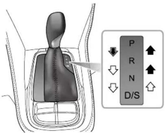
text_image
P R N D/SDuring the gear shift, operatetheshift lever according to the instructions indicated by the following arrows:

Freegearshift.

Pressandholdthelockbuttontoshiftthe gear.

Pressandholdthelockbuttonandapplythe brakepedaltoshiftgear.
ShiftLeverPosition

TheshiftlevermustbeplacedinPposition whenparked.

DONOTmovethegearshiftleverintoPor RfromDwhilstdriving,thiswillcausesevere transmissiondamageorcauseanaccident.
•PPark
Whentheshiftleverisinthisposition, the transmission willbemechanicallylocked. Use this gear only when the vehicle is stationary and the parking brake is applied.
STARTING&DRIVING
Note: Whenthevehicleisparkingonahill, press thebrakepedalandapplytheparkingbrakefirst andthenselectPgear.
•RReverse
Select this gear only when the vehicle is stationary and the engine is running at idlespeed.
•NNeutral
Select this gear when the vehicle is stationary and the engine running at idlespeed for short time (for example, waiting for traffic lights).
- DDrive
This is used for normal driving and will allow automatic selection of 6 gears depending on vehicles speed and accelerator position.
•SSportMode
Select this modewhenamoresporty acceleration performance is required.
•+Upshift
WhilstinManualmode,upshiftthetransmissiontothe nextavailablehighgear.
-Downshift
WhilstinManualmode,downshiftthetransmissionto thenextavailablelowgear.
GearshiftSpeed
SelectingDwillallowthetransmissioncontrollerto carryoutgearshiftstakinginconsiderationofanumber offactorsincludingenginespeed,vehiclespeedand acceleratorposition.Lightacceleratorpedalapplication willresultinagear-changeatlowspeeds,largerpedal applicationswillresultingear-changesathigherspeeds.
Kick-down

The drivewheelsmayskidwhenkick-downis activatedorroadsurfaceswithowadhesion, thismayleadtothevehicleslidingoutof control.
With Dgears selected, pressing the accelerator pedal all the waydowninonemotion (also known as Kick-down) will provide acceleration performance during overtaking under certain conditions, it will allow the
transmissionoshifttoalowergearimmediately, and providefastacceleration. Oncetheacceleratorpedalis released, it will resumetoasuitablenormalhighgear (based on the vehiclespeed and the position of the acceleratorpedal).
DrivingontheHill

Incaseswhereashortstoponahillis required,suchasatrafficjam,DONOT momentarilyapplytheacceleratorto prevent"rollback".Thiscouldcause thetransmissiontooverheatandresultin damage.
HillStart
Incasesofahillstart,wherethevehiclehasbeenstationary forsometime,thefootbrakehasbeenreleased and theelectronicparkingbrakeapplied,thestartingassist functionoftheelectronicparkingbrake(EPB)canbeused topreventthevehiclefromrollingbackwards.Withthe seatbeltsafelyfastened,pressthefootbrake,applythe electronicparkingbrakesystem,andselectthedesired gear(D/R/S),thenreleasethefootbrake;pressthe acceleratorpedaltoengagevehicledrive,theelectronic parkingbrakesystemwillautomaticallybedeactivated.
STARTING&DRIVING
ModelsfittedwithHillHoldControlcanusethisfunction toassisthillstarts.Fordetailsonhillholdcontrolsystem, pleasereferto"FootBrake"of"BrakeSystem"section.
Note: The assistance of these functions cannot defy the lawsof physics. DONOT drivethe vehicle beyond its physical limitations, loss of control will still occur.
DownhillDriving

Repeated application of the footbrakemay result in the brakes becoming overheated. This will cause reduction in braking performance and may even result in brake failure.
Ifdrivingdownahillforlongdistances,itisadvisedto movethegearshiftlevertotherightandselecttheManual mode.Thisallowsmanualgearselection.Usealowergear selectiontoaidtheslowingofthevehicleandthusavoiding over-useofthebrakes.Ifathresholddisreached,thevehicle willautomaticallyshiftup,inthesecasesuseofthebrakes toslowthevehicleisnecessary,atthesametimere-select thelowergear.
ControlMode
EconomyMode
SelectingDautomaticallyplacesthevehicleintheEconomy Mode.Theinformationcentredisplaywillshow"D".
EconomyModeprovidesoptimumfuelconsumptionand emissions.
SportMode
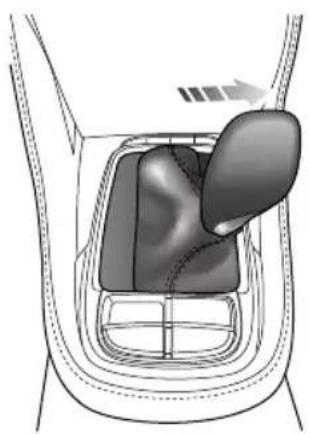
natural_image
Diagram of a car gear shift mechanism showing the wheel and gear (no text or labels)STARTING&DRIVING
OnceDisselected, movetheshiftlevertotherightto selectSandenabletheSportMode(thegeardisplayedin informationcentrechangesto"S").UnderSportMode, thetransmissionupshiftslater, soastomakefulluseofthe powerreservesoftheengine.
When better acceleration is required, please select the SportMode, but pleasenotethat the fuel consumption will be increased when driving in SportMode.
To exitSportMode, movetheshiftlevertotheleftback intoDposition.
CruiseControlMode
With the cruise control function enabled, the transmission will switch to there relevant gear for the vehicles speed automatically, thereby avoiding frequent gear shifts when the system needstomaintain a constantspeed.
ManualMode
WithSportModeselected, movetheshiftlevertoward"+"or"-", thiswillenableManualMode. Thegeardisplayed intheinformationcentrewillindicatecurrentgearwitha singlenumber(1 \~ 6).
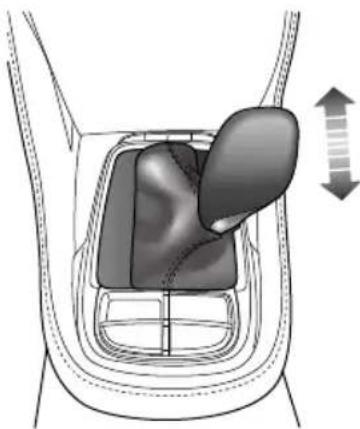
natural_image
Diagram of a car gear shift mechanism showing the lever and guide mechanism (no text or labels)Movetheshiftlevertoward“+”directiontopshifttonext availablehighgear, movetoward“-”directiontodownshift tonextavailablelowgear.
WithManualModeselected,ifthedrivermakesan unreasonablegearselection,requestsanupshiftduring lowenginespeeds,orrequestsadownshiftduringhigh enginespeeds,thetransmissionwillnotrespondandwill remaininthecurrentgealfthevehicleisdrivenand theenginespeedfallsbelowapresetthresholdin certain
STARTING&DRIVING
gears, the transmission will automatically shift downto then next gear to avoid engine stalling; when the vehicle accelerates, if the engines speed exceeds apreset limit, the transmission will automatically shift up to then next gear to protect the engine.
WithManualmodeselected, the information centrewill provide gear shift indications, the UPorDOWNarrow is displayed at therightside of the gear position number, indicating to the driver output shift order down shift when the conditions permit.
Note: The gear shift operations should be carried out on the premise of ensuring your own safety and observing the traffic regulations.
T oreturntoSportModeoranyothermodes, shift the leveracrosstotheleftandselectD.
AutomaticT transmissionFailure
If the automatic transmission develops a problem, the engine emission malfunction indicator lamp in the instrument pack will illuminate or the message centrew will display "EP".
Some "failuremodes" will cause the transmission to enter "LimpMode", during the time only certain gear positions can be selected and/or work, for example, Rgear may not be selectable. If a serious functional failure occurs the vehicle cannot be driven, please consult an MGA authorised Repairer immediately.
Not Whenthevehicleisin'LimpMode', manual gearselectionfunctionsaredisabledandthereforenot available.
STARTING&DRIVING
ManualT transmission\*
5-speedManualT transmission\*
Shiftlever
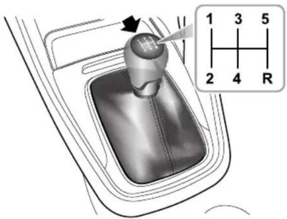
text_image
Diagram of a car gear shift lever with labeled parts and a corresponding 3D schematic showing pin assignments.Themanualtransmissionisa5-speedtransmissionwith 6gears, which are: 1st, 2nd, 3rd, 4th, 5th, R (Reverse) respectively.
Precautionswhiledriving:
I WhenselectingRgear,youmustensurethatthe vehicleiscompletelystationary,waitforamoment andthenfullydepresstheclutchpedaltocomplete thegearshift.
Please wait for 2 \~ 3 seconds before shifting to R gear, otherwise damaged the reverse gear may occur.
Please wait for 1 \~ 3 seconds before shifting to forward gear, otherwise excessive wearto the synchronizer may occur.
Donotresyouhandtheshiftevwhiledriving pressureronyouhandmaycausprematureveartothegearshiftmechanism.
3Donotrestyoufoontheclutchpedalwhendriving -excessiveweartothelutchmayoccur.
Donoholdhecastationaryonhilbyslippinghe clutch. Thiswillwearouttheclutch.
STARTING&DRIVING
GearShiftIndications
Whenthevehicleisinmotionandtheclutchpedalfully released, theinformationcentrewilldisplaythecurrently selectedgear(1-5). AnUp/Downarrowisdisplayedtothe rightofthenumberindicatingtothedrivertoeitherupshift ordownshiftwhendrivingconditionspermit.
Note: The gear shift operations should be carried out on the premise of ensuring your own safety and observing the traffic regulations.
6-speedManualT transmission\*
Shiftlever
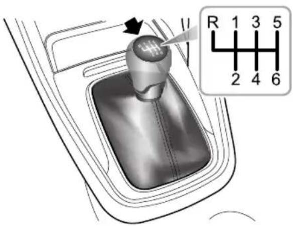
text_image
R 1 3 5 2 4 6Themanualtransmissionisa6-speedtransmissionwith7 gears, which are: 1st, 2nd, 3rd, 4th, 5th, 6th, R(Reverse) respectively.
STARTING&DRIVING
Precautionswhiledriving:
I WhenselectingReversegear ,youmustensurethat thevehicleiscompletelyinstationery,waitfora momentandthenfullypresstheclutchpedal,from theNposition,presstheleverdownandpushit leftward,thenpushitforwardintotheRposition, slowlyreleasetheclutchpedaltocompletethegear shift.
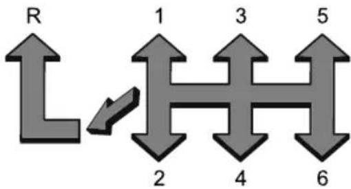
flowchart
graph TD
    R --> 1
    1 --> 2
    2 --> 3
    3 --> 4
    4 --> 5
    5 --> 6
Please wait for 2\~3 seconds before shifting gear, otherwise damaged where reverse gear may occur.
Pleasewaitfor \~ 3 seconds before shifting to forward gear, otherwise excessive wearto the synchronizer may occur.
Doorestyouhandtheshiftevwhiledriving pressurfromyouhandmaycauseprematurewear tothegearshiftmechanism.
Donotrestyoufoottheclutchpedalwhendriving -excessiveweartotheclutchmayoccur.
Donoholdhecastationaryonhilbyslippinghe clutch. Thiswillwearouttheclutch.
GearShiftIndications
When the vehicle is in motion and the clutch pedalfully released, then information center will display the currently selected gear (1-6) ArUp/Downarrow displayed the right of the number indicating the driver to either upshift or downshift when driving conditions permit.
NotEhegearshiftoperationsshouldbecarried outonthepremiseofensuringyouownsafetyand observinghetraffiaregulations.
STARTING&DRIVING
BrakeSystem
FootBrake
Foradded safety, the hydraulic brakingsystem operates through dual circuits. If one circuit should fail, the other will continue to function, but greater pedal pressure will be needed, and increased brake pedal travel, and longer stopping distances will be experienced. In the event of a brake failure where only one circuit is operational, the car should be brought to an halt as soon as a traffic conditions safely allow. DONOT continued driving-seekan MG Authorised Repairer.
ServoAssistance
Thebrakingsystemisservoassisted,alwaysbeawareof thefollowingsduringtheoperation:
- Theservoassistancefunctionswiththeengine running only.Neverallowthecartocoastwiththeengine turnedoff.
- Alwaystakeparticularcarewhenbeingtowedwithfour wheelsonthegroundandtheengineturnedoff.Ifthe engineshouldstopforanyreasonwhiledriving,bring
thecartoahaltasquicklyastrfficconditionssafely allow, and donotpumpthebrakepedalasthebraking systemwillloseanyremainingservoassistance.
• Oncetheenginehasstoppeditwillloseanyremaining servoassistance,usesuitableforcetoapplythebrake pedaltostopthecarsafelyinthecurrenttraffic conditions.ContactanMGAuthorisedRepairer.
- Efficiency of the brakeservobooster can be affected by numerous conditions, such as enginespeed loss. These conditions could result in extra forcerequired to operate the brake pedal to stop the car.
WetConditions
Drivingthroughwaterorheavyrainmayadverselyaffect brakingefficientThSC(StabilityControlSystem) includesaBrakeDiscWipingfunctionwhichisactivated whentewindscreenwipersareused. However, always keepsafedistancefromothervehiclesandintermittently applythebrakepedalinconditionswherethewipersare notused.
ElectronicBrakeForceDistribution(EBD)
Y ourcarisequippedwithElectronicBrakeForce Distribution,which,inordertomaintainbrakingefficiency, distributesbrakingforcesbetweenfrontandrearwheels, underallloadconditions.
EBDintegratesamonitoringsystem.Themonitoring systemislinkedtothebrakesystemmalfunctionindicator lampontheinstrumentpack.Referto"WarningLights and Indicators"in"InstrumentsandControls"section.
If the indicator lamp illuminates while driving, or remains illuminated after the ST ART/STOPS switch is switched ON/RUNNING, it indicates there is a failure with the braking system and BDNAP inoperatively such case stop the car as soon as safety permits and seek an MGA authorised Repairer immediately. DONOT driveth the car with the braking system malfunction indicator lamp illuminated.
ElectronicBrakeAssistance(EBA)
Y ourcarisequippedwithElectronicBrakeAssist,which reactstothespeedatwhichthebrakepedalisappliedf,
inanemergencysituationthebrakesareappliedfasterthan thelimitssetwithinthesystem,thenfullABSapplicationis appliedtobringthecartostopintheshortestpossible distance.
HillHoldControl(HHC)

HHChaslimitationswhensubjecttoadverse conditionssuchaswetoicysurfaceand steepslopes.

HHCisnotasubstituteforparkingbrake applicationwhencarryingoutahillstart. DONOTexitthevehiclewithonlyHHC applied,itmayleadtoaseriousaccident whenHHCreleases.

Thecarmayrollif pull-away'isnotachieved immediately after releasing the brake pedal.

Alwaysensurethebrakepedalispressedor electronicparkingbrakeapplieduntildriveis takenup.
STARTING&DRIVING

Firmapplicationofthebrakepedalwhen stoppingisrequiredbyHHCtogenerate sufficientbrakepressureotmaintainhold.
HHCassiststhedriverby'holding'thevehicleduringhill starts.
The following conditions must be fulfilled to activate HHC:
- Thedriver'sdoorisclosedandthedriverseatbeltis fastened.
• The vehicle is stopped on a slope for more than 2 seconds.
•SCSisactiveandfaultfree.
•EPBisreleasedandfaultfree.
- Clutchpedalispressed(MT), orinD/Rgear(AT).
- START/STOPSwitchisswitchedON/RUNNING.
- Sufficientbrakepedalapplicationforcehasbeenapplied. Ifthedriverreleasesthebrakepedalonahill, HHCwill maintainbrakepressurefor 1 -2seconds,afterthisperiod thevehiclemayrollbackwards.
Note: HHC cannot overcome physical limitations. DO NOT solely rely on HHC.
Note: HHCisavailableinbothforwardandbackward directionswhenpullingawayonuphillslopes.
HillDescentControl(HDC)
TheHDCsystemisonlyanauxiliary function. Ithaslimitationswhensubjectto adverseconditionssuchaswetoricysurfaces andsteepslopes. TheHDCsystemcannot overcomethelawsofphysics, alwaysensure thatthevehicleisdrivendownsteepslopes atlowspeeds.
EvenwhentheHDCsystemisswitchedon, thedrivermustalwayspaycloseattention tothedrivingstateofthevehicle, andtake activecontrolwhennecessary. In certain cases, HDCmaybesuspendedorswitched offtemporarily.
Duringsomedrivingconditionsdownhill surfaces(e.g.drivingdownaslopeat highspeedmalslopeetc.HDG inoperative,thedrivermustmaintaincontrol of vehicle times and brake applicationstoensuresafety.


TheHDCsystemisanauxiliaryfunctionspeciallydesigned for driving acutdownhigh gradient system reduces the speed by applying brake force, thus assisting the driver to drive on acutdownhills surfaces with low speeds.
PleaseDONOTusethisfunctionwhendrivingonthe ordinaryroads.
WhentheHDCisworkingthebrakesystemmay generatestrongvibrationsornoise.Itisnormalduring theoperationofHDC.
NoDuringtheoperationoftheHillDescent Control(HDC)system,pleaseengagealowergear onMTmodelstopreventtheenginestalling;onAT models,pleasedonotmovetheshiftlevertothe"N" positionortheHDCfunctionmaybedeactivated.
STARTING&DRIVING
HDCSystemOn/Off
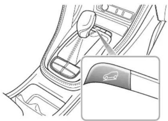
natural_image
Interior view of a car gear shift lever and dashboard (no text or symbols visible)WhentheSTART/STOPSwitchisswitched ON/RUNNING,HDCsystemdefaultstooff. Use the switchfunctionwithintheinfotainmentsystemtoturn theHDCsystemon/off.
Normally,HDCsystemhasfourstates:
I Standby: PresstheHDCswitch(ON) toset the systemintostandbymode, thegreenHDC warning lampintheinstrumentpackwillilluminate.
2OperationwhilstinStandbymode,whenthevehicle isdrivendownanacutegradient,ifthevehiclespeed islow,theHDCsystemwillautomaticallyenter theoperatingstate.Inthiscase,theHDCwarning lampintheinstrumentpackflashesgreen,thismay beaccompaniedbytheworkingnoiseofthebrake system.TheHDCsystemwillattempttocontrolthe vehicledrivedownthesteepslopesmoothly.
3T emporaryDeactivation:Presstheacceleratoror brakepedalbeyondapresetlimitwhilstinoperating modeandtheHDCsystemwilltemporarilylysuspend operation.
OffPresshdHDGswitch(OFF)to switch the system OFF, the green HDC warning lamp in the instrument pack wil le xtinguish.
Note: HDCsystemcanworkinbothforwardand backwarddirections.
Note: During HDC system operation the braking system will automatically pressurise and maintain pressure. Operation of the brake pedal during this phase may result in a kickback's sensation through the pedal. This is normal for HDC operation.
HDCON/MalfunctionIndicatorLamp
Referto"WarningLightsandIndicators"in"Instruments andControls"chapter.
Anti-lockBrakeSystem(ABS)

ABScannotovercomethephysical limitationsofstoppingthecarintooshort adistance,corneringattoohighaspeed,or thedangerofaquaplaning,i.e.wherealayer ofwaterpreventsadequatecontactbetween thetyresandtheroadsurface.
The purpose of the anti-lockbrakingsystem (ABS) is to prevent the wheels from locking while braking, thereby enabling the drivertoretainsteering control of the car.
The fact that a car is fitted with ABS must never attempt the driver into taking risk that could affect this/hersafety or other roads and are remains the driver's responsibility to drivewith innorm safety margins, having due consideration for prevailing weather and traffic conditions.
UnderormakeringconditionABSilbe activated. However, oncethebrakingforceexceedsthe availableadhesionbetweenthetiresandtheroadsurface, therebycausingthewheelstolock, ABSwillautomatically
STARTING&DRIVING
comeintooperation. This will berecognisable by a rapid pulsation felt through the brake pedal.
BrakinginanEmergency

DONOTpumpthebrakepedalatanytime; thiswillinterrupttheoperationofABSand mayincreasethebrakingdistance.
Ifanemergencysituationoccurs, the drivers should apply full braking effort to even when the roads surface is slippery. ABS will ensure that the wheels donotlock and that the car is brought to a halt in the shortest distance for the prevailing roads surface conditions.
Note: Onsoftsurfacesuchaspowderysnow, sand orgravel, the braking distance produced by the ABS system may be greater than that for an on-ABS system, even improved steering would be experienced. This is because natural action of locked wheelson soft surfacesist build up wedge of material in front of (ortotheside of, if steering) the tyre contact patch. This effect assist the cart stop when braking to changed direction when steering.
Nomatterhowhardyoubrake,youarestillableto continuesteeringthevehicleasnormal.
IMPORTANT
ABScannotreliablymakeupforthedriver's mis-operationorlackofexperience.
ABSMalfunctionIndicatorLamp
Referto"WarningLightsandIndicators"in"Instruments andControls"section.
Note: Thenormal(non-ABS)brakingsystemremains fullyoperationalandisnotaffectedbypartialor fulllossofABS. However, the brakingdistancesmay increase.
STARTING&DRIVING
AutoHold \*

Whenautoholdstopsthevehicle,forreasons suchasengineshut-down,releasingthe seatbeltorpressingtheautoholdswitch, theelectronicparkingbrakeisapplied.It cannotbeguaranteedthatthevehiclewill bestabilisedinalcases. Forexample,the rearwheelsareonaslipperyroadsurface, orthevehicleinclineistoogreat(largerthan 20%).Pleasemakesurethatthevehicleis safelystabilisedpriortoexiting.

DONOTtakeanyextrariskshendriving duetothefactthevehicleisfittedwith additionalconveniencefunctions. Thedriver shouldpayfullattentionandobservethe surroundingsevenifthevehicleisequipped withautoholdsystem.

The autohold function cannot guarantee the stability of the vehicle when starting off for braking on hills especially on slippery or icy surfaces.

DONOTleavethevehiclewhentheengine isoperatingandtheautoholdisactive.

Autohold cannot guarantee the electronic parking brake operation in all cases where the powersystem is shut down. Please ensure the electronic parking brake is applied and the vehicle is stabilised prior to exiting the vehicle.

The autohold functions should be switched off during the use of automatic car washes, the electronic parking brakemays suddenly apply and cause vehicled damage.
If the vehicle is required to stop frequently for a length of time (such as traffic lights, traffic queues or stop/start), and the engine is running, the auto holds system assists in stabilising the vehicle, enabling you to remove your foot from the brake pedal when the vehicle is stationary and the Auto Hold active.
Autoholdhas3mainstates: IOff:FunctioninOffstate.
STARTING&DRIVING
2Standby:FunctioninStandbystate.Thefunctionis activebutthevehiclehasnotstopped.Oncethe vehiclehasstopped,andallotherconditionsaremet, thesystemwillautomaticallyselectPark.
3Parking:FunctioninParkedstate.Inthisstatethe greenindicatorontheinstrumentpackilluminates.
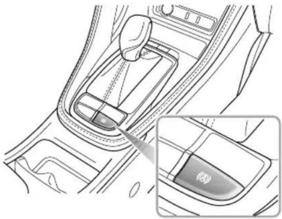
natural_image
Interior view of a car gear shift lever and intake manifold (no text or symbols visible)With the river's seabelfastened, the door closed and thengineunning press a aut hold witch switch the aut hold function from Off to Stand by state.
Withthebrakepedfirmlypressedandthevehicle completelystoppedtheautoholdfunctionwillswitch fromtheStandbystatetotheParkingstate.
Whether bolith Parking at engaging forward or reverse geand pressing the accelerator will automatically release the autohold function.
Isomeircumstancesuchseleasingsealt, switchingofftheengineorremainingstaticforalength oftimeitwillresultinthevehiclexitingtheautohold Parkingstate.Atthistimetheelectronicparkingbrake willemainappliednovilrequirchelerivetorelease iusingtheswitch.
Note: With the brake pedal pressed, operating the switch to turn the autohold off, the system will NOT apply the parking brake.
Not is recommended to turn off the autohold function when reversing into the garage.
EmergencyBrakingHazardWarningLights Control(HAZ)
If the vehicle is a travelling in excess of 31 mph (50km/h) and the driver makes an emergency braking manoeuvre, the hazard lights will be operated to indicate the other drivers.
Note: If the hazard warning lights are being operated manually, this suspend the HAZ function.
Whentheemergencybrakingmanoeuvreisexited(no severedecelerationdetected)thenthefunctionwillbe switchedoffafterafewseconds.
Note: Asthecarspeeddropstobelow6mph(10km/h) and the system no longer flashesthebrakelamps, the hazard warning lampswillilluminate automatically. Short press the hazard warning lamp switch or increase yourspeed to above 12mph(20km/h) for 5 stoswitch off the hazard warning lamps.
ActiveRolloverProtection(ARP)
TheARPsystemcannotovercomethelawsof physics.Itisadriveraidtoassistthestability ofthevehicleandunderextremeconditions. Itisnotaguaranteethatthecarwillnotroll over.
Incaseswherethevehiclehasahighcentreofmass,rapid orexcessivedualdirectionlanechangingmaycreatea rollcondition.ARPmayusethebrakingsystemtoapply certainbrakestotryandcorrecttheconditionandassist inpreventingrollover.
Note: During ARP application the steering characteristics which noticeably different from normal.
STARTING&DRIVING
ParkingBrake \*

DONOTdrivewiththeparkingbrake applied,orapplytheparkingbrakewhile thecarisinmotion. Thiscouldresultinloss ofcontrol,preventtheABSfromfunctioning correctly,andmayevencauseddamageto therearbrakes.
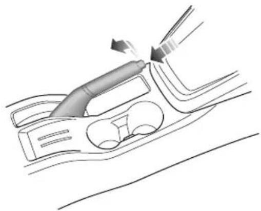
natural_image
Diagram of a medical device interacting with a car intake manifold, showing fluid flow direction (no text or labels)Theparkingbrakeoperatesontherearwheelsonly.T o applytheparkingbrake,pulltheleverup.Alwaysapplythe parkingbrakefullywheneveryouparkthecar.
T orelease,pulltheleverupslightly,pressthebutton (arrowedinillustration)andfullylowerthelever.When parkingonasteepslope,donotrelyontheparkingbrake alonetoholdthecar.
ElectronicParkingBrake(EPB) \*

IntheeventofEPBmalfunctionwhereEPB releaseisnotpossible,pleaseconsultanMG AuthorisedRepairerinordertocarryoutan emergencymanualreleaseoftheparking brake.
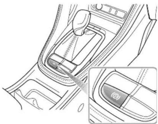
natural_image
Interior view of a car gear shift lever and dashboard (no text or symbols visible)ApplyingtheEPB
While the vehicle is stationary, the EPB can be applied. Ensure the EPB is applied every time the vehicle is leftor parked.
- Pressthebrakepedal, pulltheEPBswitchupward until the indicatorintheEPBswitchilluminates.
- If the indicator in the EPB switch and the indicator in the instrument pack illuminates, the EPB is applied.
- If the EPBmalfunction indicator lamp instrumentpackremainson, it indicates that a fault has been detected. Please contact an MGA authorised Repairer immediately.
Note: Anaudiblemotornoisemaybeheardwhen applyingorreleasingtheEPB.
IMPORTANT
•Intheeventofaflatbatteryorpowerfailure,itisnot possibletoapplyorreleasetheEPB.Insuchacase, 'jumpleads shallbeusedforemergencyenginestart, pleasereferto"EmergencyStarting"in"Emergency Information"chapter.
STARTING&DRIVING
ReleasingtheEPB
- Switchontheignition, press thebrakepedal, and press theEPBswitch.
- If the indicator in the EPB switch and the indicator in the instrument package extinguished, the EPB is released.
StartAssist
TheEPBcanpredictthedriver'sintentionand automaticallyreleasetheEPB.
If the driver's seat belt is fastened, the engine is started up, Dor R gear is selected and the accelerator pedal is depressed for start off, the EPB will automatically release.
EmergencyBrakingFunction

InappropriateuseoftheEPBcanleadto accidentsandinjuries.DonotapplytheEPB forvehiclebraking,unlessinemergency.

During emergency braking using the EPB, DO NOT switch the ignition, this could result in serious injury.
Whenthecarisinmotion,incaseofanyemergency,such asthecarcannotbestoppedbythebrakepedal,itcanbe deceleratedbypullingupandholdingEPBswitch.
• PulltheEPBswitchupwardandholdtorealisethe emergencybraking continuousacousticalarmwill soundsimultaneouslyduringemergencybrake.
- T ocanceltheemergencybrakingprocess,releasethe EPBswitch.
STARTING&DRIVING
AutomatedStop/Start—Intelligent FuelSavingSystem
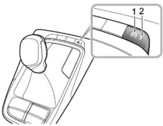
text_image
Diagram of a car interior with labeled parts, showing a seatbelt and a highlighted section with numbered labels 1 and 2.IMainSwitch
2MainSwitchIndicatorLamp
EngineStop/Starthasbeenincorporatedintovehiclesin anefforttoreduceemissions.Asthenamesuggeststhe systemwillallowtheenginetobeswitchedoffwhenengine powerisnotrequiredandthenautomaticallyberestarted whenitis.
Thissystemdefaults"on"withtheSTART/STOPSwitch intheON/RUNNINGposition,theMainSwitchIndicator Lampison(2showninfig)andcanbeturnedoffby pressingtheMainSwitch(linthefig).Thelampinthe switchwillextinguish.
Note: If vehicle is driving through deepwater, please use MainSwitch (In the fig) to shutdown Stop/Start intelligentfuelsavingsystem.
STARTING&DRIVING
AutomaticShutdownofEngine

Although the engine is not running after an automatic stop, the system is prepared to autostart therefore the following actions could be dangerous:
I Leaving the vehicle while these seat belt is still buckled, or there is as substitutes at belt buckle inserted.
2Carryingoutworkorchecksintheengine compartment.
3Refuellingthevehicle,theSTART/STOP Switchmustbeswitched"OFF"orthe keyremovedfromtheswitch.
4Vehicleswithautomatictransmission: Leavingthevehiclewhilethegear selectorisstillDriveposition(R/D/S).
EngineAutoStopConditions
EngineAutoStopConditions(UnderStartStopControl, InstrumentPackIndicatorLamp)
Vehicleisstationary, i.e. speed = 0 mph or km/h.
The vehiclespeedpriortostoppingexceeded6mph (10km/h).
VehicleswithmanuatransmissionGearboxmustben neutralandclutchpedalisreleased.
OnautomaticderivativesDselectedandthebrake pedalpressedtheenginewillautomaticallystop.Shifting thegearslectortoP/Nandreleasingthebrakepedal willmaintaintheengineshutdownstatus.
The driver's door closed and deabel-secured.
Thebonnetisclosed.
TransmissioninDrivewithfootbrakepressed.(auto only)
Nodemandsonthesteering.(autoonly)
Stop/StartProhibited
With the engine stopped in the automatic Stop/Start condition, the following driver actions will cause an automatic restart, at the time the instrument pack indicator lamp is off.
- ModelswithautomatictransmissionandinDposition: releasethebrakepedal,orshiftoutofDriveposition.
- Modelswithmanualtransmission:T transmissionin Neutralposition:presstheclutchpedaloraccelerator pedal.
Vehicles with automatic transmission Release the brake pedal with the shifel position depress the brake/accelerator pedal with the shift lever in P/N position, or shift the leverto Drive (R/D/S) position.
With the engine stopped in the automatic Stop/Start condition, the following actions will cause an automatic restart.
- Batterypowerfallsbelowapresetlimit.
- Thevacuuminthebrakingsystemfallsbelowapreset limit.
•Thevehiclebeginstomove.
•MainSwitch(linthefig)ispressed.
Atthistimetheinstrumentpackindicatorlamp extinguishtoindicateenginestartphase.

will
StartInhibition
Not specific manual transmissions under automatic Stop/Start control anthenginise required best ar but neutral positionis not selected, the enginewill restart when neutral positionis selected.
Ifanyofthefollowingconditionsoccurduringautomatic enginstoptheenginearonlyberestartedsinghkey, duringhistimetheinstrumentpackindicatorlamp extinguish.

will
• Thedriversideseatbeltisunbuckled.
STARTING&DRIVING
• Thedriversidedoorisopen.
•Bonnetisopen.
Atthistimetheinstrumentpackindicatorlampwill extinguishtoindicateenginestartphase.

StallAssist
ThisfunctionisavailableoncetheStop/Startintelligentfuel savingsystemisenabledwithoutanyinhibitingconditions. Iftheenginecutsout,orisstalledwhilstStop/Startis enabled,selectionofneutralandpressingtheclutchpedal willautomaticallyrestarttheengine.
Note:Extremelylowbatterypowermayresultinthe enginenotre-startingautomatically,orevenusingthe key.Inthisinstance,externalpowerisneededtostart theengineorthebatterywillrequirere-charging.See thesection'EmergencyStarting'inthe'Emergency Information'Chapter.
Battery

Whenchargingthebattery, startingthecar withanexternalpowersourcesupplying powerfromthevehicle, thenegativecable mustbeconnectedtoasuitablepositionon thevehiclebody. Failuretodothiswillresult ininaccuratebatterypowercalculation whichwilleffectautomaticStop/Start control.

DONOTdisconnectthebatterysensor unlessabsolutelynecessaryval willresultaccuratebatterypower calculationwhichwilleffectautomatic Stop/Startcontrol.
No residue to operate within the following guidelines, if batte performance and automatic Stop/Start control: Afterpower interruptions(battery disconnection) thetomaStop/Stefunctiabil suspended until the vehicle is left in locked state
foratleast4hourswhilstthesystemrelearnsthe stateofthebattery.
2Ifthevehicleisruncontinuallyformorethan100 hoursuninterrupted,theStop/Startfunctionwill besuspendeduntilthevehicleisleftinalocked stateforatleast4hourswhilstthesystemrelearns thestateofthebattery.
3Ifthebatteryrequiresreplacement,ALWAYSusea genuineparttothemanufacturersspecification.
Failuretoadheretothiscanaffecttheautomatic Stop/Startsystem.
AutomatedStop/StartIntelligentFuel SavingSystemFailure
IntheeventofaStop/StartIntelligentFuelSavingSystem failure,contactanMGAuthorisedRepairer.
TheStop/StartIntelligentFuelSavingSystemcanbe effected by a fault within the vehicle system is the event of failure contact an MGA authorised Repairer.
Starbeoperatior;Battery CapacityLoss
In these ferious batteries, powelos automatic Stop/Start and keyst start may not be possible. In this case seethese section Emergency Starting in the 'Emergency Information' Chapter.
STARTING&DRIVING
StabilityControlSystem(SCS) and T ractionControlSystem(TCS)
StabilityControlSystem(SCS)
SCSisdesignedtoassistthedriverincontrolofdriving direction. TheSCSisautomaticallyactivatedafterthe engineisstarted.
WhenSCSdetectsthatthevehicleisnotmovinginthe intendeddirection,itwillintervenebyapplyingbrakeforce toselectedwheelsorthroughtheenginemanagement systemtopreventslidingandassistinbringingthecarback totherightdirection.
T ractionControlSystem(TCS)
The purpose of electronic traction control is to aid traction, thereby helping the driver to maintain an control of the carinsituations where one or both of the driving wheels are spinning (forexample, if onewheel is onice and the other on tarmac). The traction control system monitor the drivings speed of each wheel individually. If spin is detected on one new wheel, the system automatically brakes that wheel, transferring torque opposite,
non-spinningwheel.Ifbothwheelsarespinning,the systemwillreduceenginespeedinordertoregulatewheel rotationuntiltractionisregained.
SwitchingOn/Off
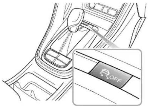
natural_image
Interior view of a car gear shift lever with a highlighted 'R_OFF' button (no text or symbols beyond the label)With the START/STOP switch is switched ON/RUNNING, SCS and TCS will automatically turn on. And you can turn them off after the engine is started.
STARTING&DRIVING
- PressSCSswitch(lessthan2seconds)toturnoffTCS.
- PressSCSswitch(longerthan2seconds)toturnoff SCSandTCS.
Note: PresstheSCSswitch(morethan 10 seconds), itwillberegardedasmisoperation.
- T overrecovertheoperationofSCSandTCS,pressSCS switchonceagain.
Note: Disabling SCS and TCS will not affect the operation of ABS. Always disable TCS when driving with snow chains fitted.
StabilityControl/TractionControlWarning Lamps
Referto"WarningLightsandIndicators"in"Instruments andControls"section.
STARTING&DRIVING
CruiseControlSystem
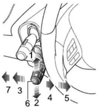
text_image
1 7 3 6 2 4 5-Acceleration(I)
•CruiseResume(5)
- Deceleration(2)
•CruiseSet(6)
• CruiseCancel(3)
•ASLStandby(7)
•CruiseStandby(4)
Cruisecontrolenablethedrivertomaintainaconstant roadspeedwithoutusingtheacceleratorpedal. This isparticularlyusefulformotorwaycruising,orforany
journeywhereaconstantspeedcanbemaintainedforalengthyperiod.
CruiseControlSystemActivation
Cruisecontrolsystemisoperatedwithaleverlocated,at theleftsideofthesteeringwheelunderneaththelighting stalkswitch.
WiththeSTART/STOPSwitchinpositionON/RUNNING, iftheleverswitchisinthe'ASLStandby'position(7 infigure),thenthecruisecontrolisOFF .T osetthe cruisecontrolto'Standy'pulltheleverswitchto'Cruise Standby'(4infigure),theyellowindicatorlamp inthe instrumentpackwillilluminateindicatingthesystemisin 'CruiseStandby'mode.
With the system in Standby when the current vehicle speed is above 25 mph (40 km/h), pressthe 'Cruise Set' button (6 figure). The indicator in the instrument pack will chan get ogreen and the cruise control will enter and activated state. The operating range is 25-125 mph (40-200 km/h).
STARTING&DRIVING
Thetargetspeedofthecruisesystemwillbesetatthe currentspeed,andthecruisesystemwilltakeeffect.At thistime,thecruisecontrolsystemwillmaintaintheset speedwithoutpressingtheacceleratorpedal.
Note: Thesetspeedheldinthecruisecontrolmemory will be cancelled when either the cruise control lever is switched to "ASL Standby" position (figure 7) or the START/STOP switch turned off.
T argetCruiseSpeedAdjustment
Whenthecruise controlisactive, the 'targetspeed' can be increased or decreased:
Pushtheleverswitchupwards(1 figure), this will increasethespeed.
Pushtheleverswitchdownwards(2infigure), this will decrease the speed.
Releasetheleverswitchwhenthedesiredspeedisreached.
Pushtheleverswitchupwardsordownwardsbrieflyto increase/decreasethevehicletargetspeedinincrementsof
Imph(1km/h), thenthevehiclewillaccelerate/decelerate tothenewtargetspeed.
Pressingtheacceleratoratanytimewilloverridethecruise controlandallowaccelerationtoundertakemanoeuvres suchasovertaking.Releasingtheacceleratorwillreturn thevehicletothesettargetspeed.
Pause/StandBy
Cruisecontrolwillbedisengagedandsetto'Standy'if:
- Leverswitchmovedto'CruiseCancel'position(3in figure).
- Brakepedalpressed.
•AutogearlevermovedtoP, RorN.
•Manualgear-changemade. - Clutchpedalpressed.
•ConditionsinitiateSCSintervention.
• Aninclinecausesexcessivedeclineinspeed.
Resume
If the cruise control remains on after the disengagement, moving the leverswitch to 'Cruise Resume' (5in figure)
STARTING&DRIVING
willreinstatethetargetspeedtothesettingpriorto disengagement.
Note:
- Neverusethecruise control system in thereverse gear.
•DONOTusethecruise control in unsuitable conditions, such as on slipper surfaces, excessively heavy rain or in traffic condition that DONOT suit maintenance of constants speeds. - Whennotinuse,ensuretheleverswitchisinthe 'ASLStandby'position(7infigure).
- Whentheautomatictransmissionisin "Sport" mode, it is not recommended to set the cruise control system.
- During the operation of cruise control system, the actual speed may deviate from the target cruise speed to some extent duetoroad conditions (such as uphill, downhill, etc).
- If the actualspeedis excessively lower than the targetspeedorSCSisactivatedduetothehill orroadsurfaces, the cruise control system may automatically revert to standby mode.
•DONOToperatetheswitchforexcessivelylong periods,orpressmultipleswitchessimultaneously, thismaycausethesystemtofail.Ifthissituation occurs,whenitissafetodoso,cycletheignition.
STARTING&DRIVING
ActiveSpeedLimit(ASL)System
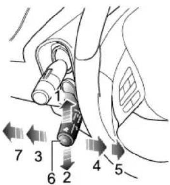
text_image
1 7 3 6 2 4 5I. SpeedLimitIncrease5. CruiseResume
2.SpeedLimitDecrease6.Set(Activate)
3. CruiseCancel7.ASLStandby
4. CruiseStandby
TheActiveSpeedLimit(ASL)systemisdesignedtocontrol thevehiclespeedkeepingitbelowaspeedsetbythedriver.
TheASLsystemsharesthesameleverswitchasthecruise controlsystem, located to the left of the steering wheel below the indicator that switch can be toggled between both functions, however only one function can operate at any onetime.
Activate
ThedesiredtargetspeedoftheASLsystemisdisplayedin theinstrumentinformationcluster,referto"Information Centre"inthe"InstrumentsandControls"section.With theSTART/STOPSwitchinpositionON/RUNNINGand theleverswitchin"ASLStandby"(7infigure),theASL functionisinstandbymodebydefault,brieflymovingthe leverswitchup/down(1,2)adjuststhetargetspeedofthe ASL.Therangeoftargetspeedadjustmentis20-130mph.
Thetargetspeedlimitvaluewillbeincreasedordecreased by5mpheverytimetheleverswitchisbrieflymoved upwardsordownwards.
STARTING&DRIVING
Pressingthe"Set"button(6infigure)willactivatetheASL systemandsetthespeedlimit.TheASLindicatorlampin theinstrumentpackwillilluminate.
Whenactivatedifthevehiclespeedisgreaterthanthe userinputtedtargetspeedthesystemwillimmediately begintoslowthevehicletotheinputtedtarget.
KickDown
With the system active if it is necessary to accelerate the vehicle.e. overtaking manoeuvre, the system can be over ridden by pressing the accelerator pedal passed a kick down position. The kick down position is approximately at the overall accelerator pedal travel pressed. On the kick down position has been reached the ASL system enters a standby and return the vehicle operation to the user, accelerating according to the demand from the accelerator pedal.
Afterakickdownevent, oncethevehiclespeedhas droppedbelowthetargetspeedoriginallycontrolledto, theASLsystemwillautomaticallyresumeandcontrolthe vehicletothetargetspeedretainedwithinthesystem.
SuspendingASL
WhenASLisactive, tosuspend the feature press the "Cruise Standby" button(4) and the ASL system will exit to the stand by a statereturning control to the accelerator pedal.
Note: Whensuspended via the "Cruise Standby" button(4) the previously inputted targets speed will be retained within the system memory in the casethat the system is reactivated.
ResumingASL
If the system has been placed in a stand by state with a retained targets speed the system can be reactivated to the previously stored targets speed by pressing the "Set" button.
Note after the ignition is switched OFF, the target speed previously stored will be erased. In the interest of economy and safety, it is recommended to select different targets speeds according to different driving and road conditions.
OvershootofTargetSpeedandWarning
Thesystemisdesignedtocontrolthevehiclespeedto within+/-1.5mph(2km/h)oftheinputtedtargetspeed. However, thefeaturedoesnotincorporatevehiclebraking assist, thereforeiftheASLsystemisattemptingtocontrol vehiclespeedonasteepdownhillinclinetheinertiaof thevehiclemayforcethevehiclespeedovertheintended targetspeed.
Ifatanytimethevehiclespeedincreases2mph(3km/h) morethanthedesiredtargetspeedthesysteminformsthe userwithcontinuousvisualandperiodicaudiblewarnings. Oncethedesiredtargetspeedhasbeenmaintainedthe warningsareremoved.
Note: If the targets speed has been deliberately exceeded. e. KickDown, only a visual warning is displayed.
STARTING&DRIVING
ParkingAidSystem \*
UltrasonicSensorParkingAid \*

The purpose of the parking aid to assist the driver in reversing! Thesensors may not be able to detect obstacles of certainty, e.g. narrow posts or small objects nom more than afewincheswide, small object closeto the ground, objects abovethetail gate and some objects with non-reflectives surfaces.

Keepthesensorsfreefromdirt,iceandsnow. Ifdepositsbuilduponthesurfaceofthe sensors,theirperformancemaybeimpaired. Whenwashingthecar,avoidaiminghigh pressurewaterjetsdirectlyatthesensors fromcloserange.
RearParkingAid
The ultrasonicsensors in therear bumper monitor the area behind the vehicle to search for obstacles. If any obstacle is detected, the system will calculate its distance from the rear of the vehicle and communicate them message to the driver by sounding warning chimes.
ParkingAidinOperation
When the START/STOP switch is in the ON/RUNNING position, there are parking and is enabled automatically when reverse is selected, it is switched off as soon as reverse is disengaged. A short beep is given by the parking aid within 1 second after selecting reversetoin indicate that the system is operating normally.
The entertainmentsystemscreenwilldisplayasilhouette imageofthecarshowingtheobjectdistancevaluesforthe sensor.
Note: Ifalonger, higherpitchedsoundisemitted for 3 seconds when reverse is selected this indicates a fault in the system. In this case seek assistance from your MGA authorised Repairer.
STARTING&DRIVING
With the parking aid enabled, when obstacles are detected, the system will give sounds in different frequencies (there might be blind areas).
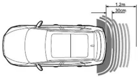
text_image
1.2m 30cm- Oncetheobstructioniswithin30cmrangeoftherear bumper,thebeepswillmergeintoacontinuouswarning.
• If there is an obstacle within 1.2m range from there are sensors, the system start to emit abepingsound. As the vehicle moves closerto the obstacle, the beeps are transmitted more rapidly.
STARTING&DRIVING
360PanoramicImagingSystem \*

The purpose of the 360 panoramic imaging systemistoassist the driver during reversing! The camerashave alimited field of view and cannot detect obstructions outside the field of view.

Although the entertainment display can provide high-definition images around the vehicle, please still pay attention to the current actual road conditions for your drivingsafety.
Withthe360panoramicimagingsystemworking,the displayinterfacewillshowa360°panoramicimageofthe vehicletofacilitatetheobservationofthesurrounding environmenttomakedrivingsafer.
- Whenthereversegearisselected, thesystemwill automaticallyswitchtothedisplayinterfaceofa360° panoramicimage, thiswillappearintheentertainment display.
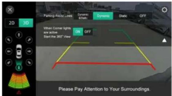
text_image
Parking Assist Links Dynamic Static Dynamic Static OFF 2D 3D When Corner lights are active Start the 360° View ON OFF Please Pay Attention to Your Surroundings.- Touchorpressthe360°Viewbuttontoenterintothe displayinterfaceofthe360panoramicimagingsystem, youarethenabletotouchbuttonsonthedisplayto checkimagesfromdifferentanglesofviewofthevehicle toprovideamuchsaferdrivingenvironment.
Touch the 2D3Button the display center intothedisplayinterfaceofthe2Dor3Dpanoramic imaging system, you are he able to touch different areasaroundthevehicle(asdisplayedontheLHside ofthescreen)tocheckimagesfromdifferentanglesof viewtoprovideamuchsaferdrivingenvironment.
TouchtheSettingbuttonirtheupperrightcornerofthescreentcopentheSettingsInterfacehereyourable
STARTING&DRIVING
toswitchthe"whencornerlights/indicators*areactive startthe360°view"functionON/OFF .Whenaforward gearisselectedandtheleft/rightcornerlight/indicator* ison,the360panoramicimagesystemwilldisplaythe correspondingleft/rightview.
- Touch the Setting button in the upperright corner of the screentoopenthe 'Settings' interface, here you are able to set the parking aid linetostatic, dynamic, dynamic + static, and off state.
Note: Whentheshiftleverisplacedinforwardgear position, innocasecan360panoramicimagingsystem beenabledaslongasthevehiclespeedexceedsore equalsto 10mph(15km/h).
STARTING&DRIVING
RearDriverAssistanceSystem \*
SystemOverview

Theeffectiverecognitioncapabilitiesofthe rearsensorscanbelimitedbyobjectssuch asroadsidebuildings,guardrails,changesin pitchangleofthecarduetoheavyloading, roadconditionssuchasbendsorbumpsor weatherconditionssuchassnowandiceetc. Anyoftheabovemaytriggerafalsealarm.

Thereardriverassistsystemmaynotprovide adequate warning of very fast approaching vehicles or operate correctly on tight curves of 500 m radius or less.

Thereardriverassistsystemwillnotoperate correctlywhilsttowingatrailerorcaravan.

Thesystemhaslimitationsandmaynotbe abletowarnofvehiclesapproachingathigh speeds.

Thereardriverassistancefunctionisonlyan aid,itisNOTasubstitutefortheattention ofthedriver. Thedrivermustalwaysremain incontrol,observethesurroundingsanddrive safely.

The correct operation of therearsensors will be compromised if they are misaligned due to accident damage. This may cause the system to automatically shutdown.

Toensurethattheradarsensorswork correctly, therearbumpershouldbekept freeofsnowandiceandmustnotbecovered.

Useofnonrecommendedmaterialsor paintonrearbumperrepairsmayhavea detrimentaleffectontheoperationofthe rearsensorPleaseonlyuser recommended materials.
STARTING&DRIVING
Thereardriverassistancesystemincludesblindspot detection(BSD),lanechangeassist(LCA),andrearcross trafficalert(RCTA)functions.
Thereardriverassistancemodulesaremountedatthe rearofthevehicleoneachside,theycanassistindetecting vehiclesbehindortothesideofyourvehicle.
Thewarninglampstosupportthissystemarelocated withintheLHandRHdoormirrorglasses,theywill illuminateorflashtowarnofanapproachingobjectorcar toassistyouinmanoeuvringthecarsafely.
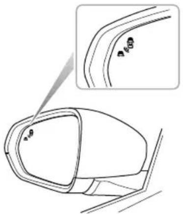
natural_image
Technical line drawing of a car side mirror with an inset showing a detail (no text or symbols)Note: Theradarrequirescalibrationonnewvehicles orforvehiclesofwhereareardetectingradar sensorhasbeenreplaced. Thereardetectionradar sensorspossessanautomaticcalibrationfunctionto compensateforinstallationerrorwithinacertain range. Whenthevehicleisrunning,theradarwill automaticallyenterthecalibrationstate.Duringthe calibrationprocess,thesystemwillprovidelimited functions,andthealarmmaybeinaccurateUpon
STARTING&DRIVING
completionofthecalibration,thesystemwillresume allfunctions.
SwitchingtheSystemFunctionsOn/Off
Thereardriverassistsystemfunctionandsubsystem switchescanbeaccessedviatheinfotainmentscreen.
Select:'VehicleSettings','DrivingAssist'and'RearDriving Assist'(youmayhavetoscrollleftorrighttoaccessthis option).SelectON/OFFtoactivate/deactivatethesystem. A warningmessagetoalertyouofyourchoicewillbe displayedinthemessagecentreintheinstrumentpack.
Whenthevehicleisrestarted,thesystemwillkeepthe previouslystoredswitchsettings.
SystemFunctions
Note: The detection area, collision timethreshold value and vehicle speed provided in the system function description are just for your reference.
BlindSpotDetection(BSD)
Whenthevehicleisdrivingforwardhesystemwill monitorthemotorvehicleslocatedintheblindzonesof theleftandrightexteriormirrors.Whentheconditions foractivatingtheblindspotdetectionfunctionaremet,the warninglampsinthecorrespondingmirrorwillilluminate. Subsequentoperationoftherelevantindicatorwillcause thewarninglampinthemirrortoflashtoremindthe driverofanapproachingvehicle.
STARTING&DRIVING
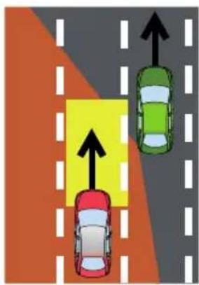
text_image
Diagram showing three cars on a road with directional arrows indicating movement or traffic flowThe conditions for activating the blind spot detection function include:
IReardriverassistancesystemisintheONstateand nofaultsarepresentinthesystem.
2Blindspotdetection(BSD)functionisenabled.
3Thevehiclespeedisabove20mph(30km/h).
4Therearemotorvehiclesintheblindzoneofthe vehicle.Thesystemmonitorsboththeleftandright
ofthevehicle,themonitoredareasare2mahead,7m behindtherearofthevehicle,and4.7mfromtheside ofthevehicle.
Note: The warning lampswill not to illuminate whilst you are overtaking another vehicle and your speed is greater than that of the vehicle you are passing, even though it is in the blind zone.
STARTING&DRIVING
LaneChangeAssist(LCA)
Whenthevehicleisdrivingforward,thesystemwill monitorthemotorvehiclesapproachingrapidlyinthe adjacentlanes.Whentheindicatorsareactivated,andthe conditionsforactivatingthelanechangeassistfunction aremet,thesystemwillflashtehwarninglampwithinthe respectivemirrortowarnthedriverofanapproaching vehicle.Thisaimstohelpavoidcollisionswhenchanging lanes.
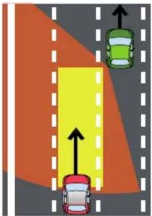
natural_image
Diagram showing two cars on a road with directional arrows indicating movement or flow (no text or symbols)The conditions for activating the lane change assist function include:
IReardriverassistancesystemisintheONstateand nofaultsarepresentinthesystem.
2Lanechangeassist(LCA)functionisenabled.
3Thevehiclespeedisabove20mph(30km/h).
4 Thespeedoftheapproachingvehicleishigherthanthe speedofyourvehicle.
5Theapproachingvehicleentersthedetectionareaof theLCA,themonitoredareasare7-70mbehindyour vehicleand4.7mtothesideofyourvehicle.
6Theapproachingvehicleislikelytohaveacollisionwith yourvehiclewithin3.5seconds.
STARTING&DRIVING
RearCrossT rafficAlert(RCTA)
Whenthevehicleisreversing,thesystemwillmonitor vehiclesapproachingfromtheleftandrightrear.When theconditionsforactivatingRCTAfunctionaremet,the warninglampsinthemirrorsonthecorrespondingside willilluminate,simultaneouslyawarningtriangleiconfor thecorrespondingsidewillbedisplayedintheinfotainment screentoalertthedrivertothesituation.
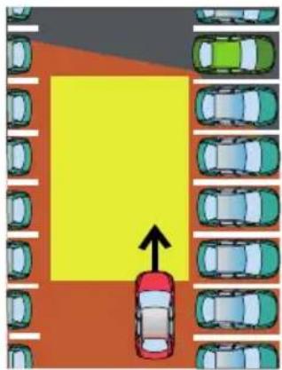
natural_image
Top-down view of a parking lot with multiple lanes and a central yellow area marked by an arrow (no text or symbols)The conditions for activating there are cross-traffic alert function include:
IReardriverassistancesystemisintheONstateand nofaultsarepresentinthesystem.
2Rearcrosstrafficalert(RCT A)functionisenabled.
3ThevehicleisinReversegear.
4Thevehiclespeedislessthan5mph(9km/h).
5Thespeedofthevehiclebeingmonitoredisabove 5mph(9km/h).
6Themotorvehicledrivesacrossthesystemdetection areas. Theareasmonitoredtotheleftandrightofthe vehicleare5mbehindtherearofthevehicle,and25m fromtheside.
7Theapproachingvehicleislikelytohaveacollisionwith yourvehiclewithin2.5seconds.
STARTING&DRIVING
T yrePressureMonitoringSystem (TPMS)

TPMScannotreplaceroutinemaintenance andcheckofthetyreconditionorpressure.

Ifradiotransmissiondevicessuchasmobile telephonesorwirelessheadsetsareusedin closeproximitytothevehicleitmayresult ininterferencewiththeTPMSandcould registerasafault.
Note: TPMSonlygivesthedriverawarningwhenthe tyrepressureislow, itwillnotinflatethetyre.
TPMSusespressuresensorsbuiltintotyrevalvesto continuouslymonitorpressureandtransmitssignaltoECU insidethevehicleusingRFsignals.lfiteducesethatthe pressureofthattyrehasfallenbelowthepredefinedlimit ofthesystem,thewarninglightontheinstrumentpackwill illuminate(alwaysyellow).Formoreinformation,please referto'InstrumentPack'in'InstrumentsandControls' section.Checkyourtyresattheearliestopportunityand
reinflatetothecorrectpressure.Pleasereferto'Tyre Pressure(Cold)'in'T technicalData'section.
SystemMalfunction
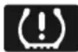
Thisystemisself-monitoring,ifamalfunction, theTPMSwarninglamp(yellow)onthe packwillflashfor90secondsfirstandthen
Note: When apuncture is detected, the system will require some time to analyze information prior to illuminating the warning lamp.
Undercertainconditionsthewarninglightmayilluminate whenafaultisnotpresent,theseconditionsinclude:
Anonrecommendedtyrefitted(includingsparetyre). Roughterraindrivingforexcessiveperiods.
Bendingormountaintypeterraindrivingforexcessive periods.
TPMSwillnotrespondimmediatelyifatyre'blowsout'.
STARTING&DRIVING
TPMSSelf-learning
TheTPMSsystemisa'selflearning'system,afterresetting tyrepressuresitwillbenecessarytoallowthesystemto gothroughaselflearningprocess.Thisisdonebydriving thecar,duringthisprocessthesystemissuspendedandthe datadisplayedmaynotbecorrect.Ifsensororreceiver modulearereplacedthesystemrequiresprogramming, consultanMGAuthorisedRepairer .Ifthewheelsare swappedorrotatedthesystemrequiresreprogramming tolearnthenewtransmitterpositions,consultanMG AuthorisedRepairer.
STARTING&DRIVING
LoadCarrying

DONOTexceedthegrossvehicleweight orthepermittedfrontandrearaxleloads. Failuremayresultinvehicledamageor seriousinjury.
LoadSpace

Ensure that there are seat backrests are securely latched in the upright position when loads are carried in the load space behind theseats.

Ifthebootlid(ortailgate) cannot be closed duetothetypeofcargoloaded, besureto closeallwindowsduringdriving, select the facedistributionmodeoftheaircondition, andsettheblowertomaximumspeed, so astodecreaseexhaustfumesenteringthe vehicle.
When luggage carried in the boot, always ensure heavy items are placed as low and forward as possible, so
astoavoidthecargoshiftintheeventofanaccidentor suddenstop.
Drivecarefully and avoid emergency braking or maneuvers when large or heavy items are carried.
Drivingwiththebootlid(ortailgate)openisverydangerouftheloadbeingcarriedrequiresthebootlid(ortailgate)tobeopen,pleaseensurethecargoandthebootlid(ortailgate)aresuitablysecuredandeverymeasureistakentopreventexhaustfumesenteringthevehicle.
IMPORTANT
Traffic regulations must observe the loading cargo, if the cargo extrude the load space, appropriate warning measures must be taken to warn other road users.
InternalLoading

DONOTcarryUNSECUREDEQUIPMENT,tools orluggagethatcouldmove,causingpersonal injuryintheeventofanaccident,emergency brakingorhardacceleration.

DONOTobstructthedriverandpassengers tokeeprightsittingpostureandobservation withloads.
Foldingtherearseatscanincreaseluggagespace,referto "RearSeat"in"SeatsandRestraints"chapter.
Whencargoisloadedinthevehicle,placeitataposition aslowaspossibleandensurethatitistightlysecured,soas toavoidpersonalinjurycausedbycargomovementwhen trafficaccidentsoremergencybrakesoccur.Ifthecargo hastobeputonaseat,nooneisallowedtositonthat seat.
GeneralT owingSafety
Y ourvehiclecantowatrailerifyoucarefullyobserveload limits,useapprovedequipment,andfollowthetowing guidelines.Alwayscheckloadlimitsbeforetowing.
T owingloadsinexcessofthemaximumtowingweight canseriouslyaffectvehiclehandlingandperformance,and coulddamageyourvehiclesengineanddrive-train.
Note: Exceeding any load limits advised by MGMotor UK Ltd is dangerous. Consult there recommended load limits and loading prior to any journey.
Checktheloadingofyourvehicleandtrailer carefullybeforestartingtodrive.
T railerhitchloadshouldneverexceedthelimitadvisedby MGMotorUKLtd.
Note: Excessivetowing loads reduce frontty retraction and steering control, to little trailernoseload can make the trailer unstable and cause it to say.
T owbars:OnlygenuineMGapprovedtowbarsshould befittedtoyourvehicle.Onlyusetheattachmentmethod specifiedbythevehiclemanufacturerforsecuringthe
STARTING&DRIVING
towinghitch.ContactyourauthorisedMGdealerfor moreinformation.
Safetychains: Safetychains must be used as a precautionary measures should the trailer become unintentionally unhitched. Makes sure the safety chain is securely attached to both the trailer and the vehicle prior to departure.
Altitude: Y ourenginedeliverslesspowerathigher altitude, fotovrailemountainouare you should reduce the combined vehicle and trailer weight by 10%forevery1000mofelevation.
Gradients: Where possible when owing should play out journey, avoid teegradients. Advised braketowing mass stated assumes a maximum gradient capability of 2% where possible recommended you drive on gradients less than 2% follow the trailer associations recommendations for suitable roads.
RunningperiodAvoidowingtraileduringour vehiclesfirst1000kmor625miles.
Stop/StarfunctionManually switch the Automated Stop/StarfunctionOFFwhertowingTheraileweight
canaffectyourvehiclesbrakingefficiencyifAutomated Stop/Startisactivatedonahillwhiletowingatrailer.
EmergencyInformation
226HazardWarningDevices
228EmergencyStarting
230 VehicleRecovery
235TyreRepairandWheel Replacement
242FuseReplacement
250 BulbReplacement
EMERGENCYINFORMATION
HazardWarningDevices
HazardWarningLights
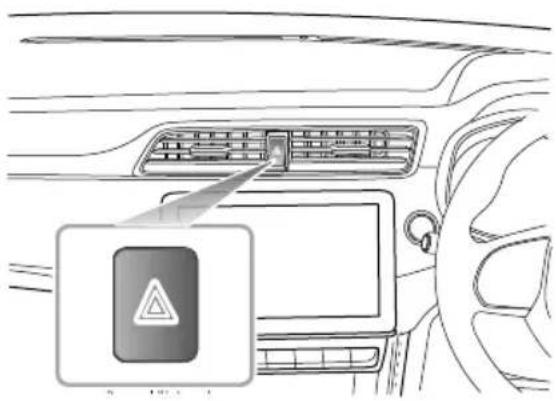
text_image
Diagram showing car interior with a warning sign and a warning triangle icon, likely indicating hazard or hazard.Note: Before you stop a slow the carinan emergency, always press the hazard warnings switch. All the direction indicators will flash together to warn other road users when your car is causing an obstruction or
isinahazardoussituation.Remembertoswitchchoff beforedrivingaway.
WarningT triangle
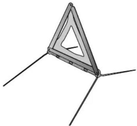
natural_image
3D diagram of a triangular structure with three legs and internal cutouts, no text or symbols presentThe warning triangles supplied with your carisstowed in the load space.
If you havetostopy our carontheroadinan emergency, you must place awarning triangle approximately 50-150
EMERGENCYINFORMATION
metresbehindthecar,ifpossible,towarnotherroadusers ofyourposition.
EMERGENCYINFORMATION
EmergencyStarting
UsingBoosterCables

NEVERattempttostarttheengineby pushingortowing.

Makesurethatbothbatteriesareofthesame ratedvoltage(12volts),andthatthebooster cablesareapprovedforusewith 12voltcar batteries.

Ensuresparksandnakedflamesarekeptwell awayfromthefrontcompartment.
Usingboostercables(jumpleads)fromadonorbattery, orabatteryfittedtoadonorvehicle,istheonlyapproved methodofpoweringacarwithaflatbattery.
If the battery from donor vehicle is to be used, makes sure that the vehicles are parked so that the two batteries are adjacent to one another and that both the vehicles donot touch.
StartingtheCar

Ensure that each boostercable connection is securely made. Theremust benorisk of the clips accidentally slipping from the battery terminals (as a result of engine vibration, for example), this could cause sparking, which could lead to fire ore explosion.
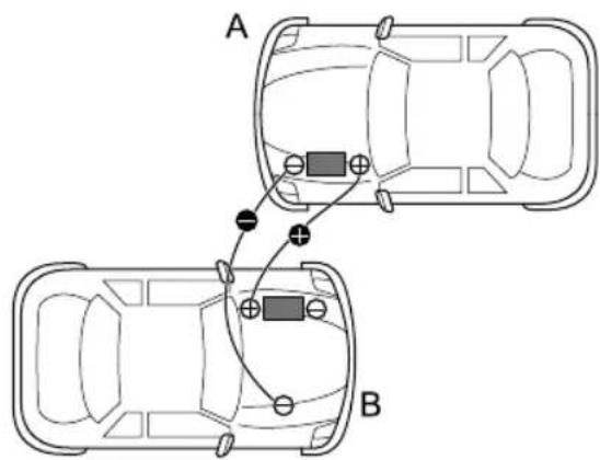
text_image
A BEMERGENCYINFORMATION
EnsuretheSTART/STOPswitchisturnedoffandswitchchoff ALLelectricalequipmentofBOTHvehicles,thenfollowthe instructionsbelow:
ConnecttheREDboostercablebetweenthepositive (+)terminalsofbothbatteries. ConnecttheBLACK boostercablefromthenegative(-)terminalofthe donorbattery(A)toagoodearthpoint(anengine mountingorotherunpaintedsurface,forexample),as farawayfromthebatteryaspossibleandwellaway fromfuelandbrakelinesonthedisabledvehicle(B).
2Checkthatthecablesareclearofmovingpartsofboth engines,thenstarttheengineofthedonorvehicleand allowittoidleforafewminutes.
3Nowstarttheengineofthevehiclewiththe dischargedbattery(DONOTcranktheenginefor morethan10second)thedisabledvehiclewill notstartafterseveralattemptsitmayneedobe repaired.PleasecontacttheMGAuthorisedRepairer.
4Afterboththevehicleshavenormallystarted,allow theenginestoidleformorethan2minutesbefore
shuttingdowntheengineofthdonorvehicleand disconnectingtheboostercables.
Important
NEVERturnonanyelectricalequipmentonthe startedvehiclebeforeremovingtheboostercables.
5Disconnectingtheboostercablesmustbeanexact reversaloftheprocedureusedtoconnectthem,i.e. disconnecttheBLACKcablefromtheearthpointon thedisabledvehicleFIRST.
EMERGENCYINFORMATION
VehicleRecovery
T owingforRecovery
T owingEye

DONOTuseatowropethatistwisted-anyuntwistingforcecouldunscrewthetowingeye.
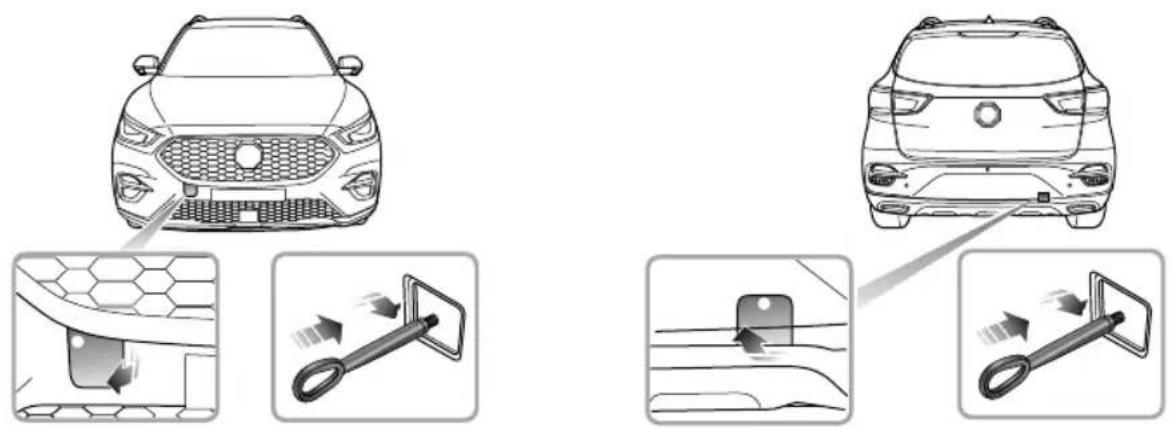
EMERGENCYINFORMATION
Y ourcarisequippedwitharemovabletowinghook,that canbeusedatthefrontortherearofyourvehicle.The towinghookisstoredinthetoolkitbeneaththeloadspace floorwhennotinuse.
T ofitthetowinghook,firstpressoneendofthesmall coverplate(thewhitedotinthefigureabove),thenopen thesmallcoverplateaftertheotherendislifted,then screwthetowinghookthroughthesmallholeinto the threadedholeonthebumperbeam(asshowninthe figure).Ensurethetowingeyeisfullytightened.
Note: Thetowingeyecovermaybesecuredtothe bumperbyaplasticcord.
Bothtowingpointsareintendedforusebyqualified recoveryspecialiststoassistintherecoveryofyourcar whenabreakdownoraccidentoccur,suchaspullingyour vehicleontothetrailer ,etc.Theyarenotdesignedfor towingothervehicles,andmustNEVERbeusedtotowa trailerorcaravan.Thecarcanbetowedbyusingasoft rope,butahardrodispreferred.
T owingforRecovery
If, duetoanelectrical fault, potential safety hazards may exist, it is not allowed to put the START/STOP switch in the ON/RUNNING position.
Whentowing, DONOTsuddenlyaccelerate orbrakesuddenly, this can cause accidents.
Thetowingspeedofvehiclemustnot exceed 20p(50m/h)twing distanceshallnotexceed30miles(50km).
SuspendedTowing
If your car need stobetowed, most qualified recovery specialists will use wheel lift equipment to suspend the front wheels, while therear wheels remain on the ground. Ensure the parking brake is released, the hazard warning lamps are activated and passengers are for the vehicle.
EMERGENCYINFORMATION
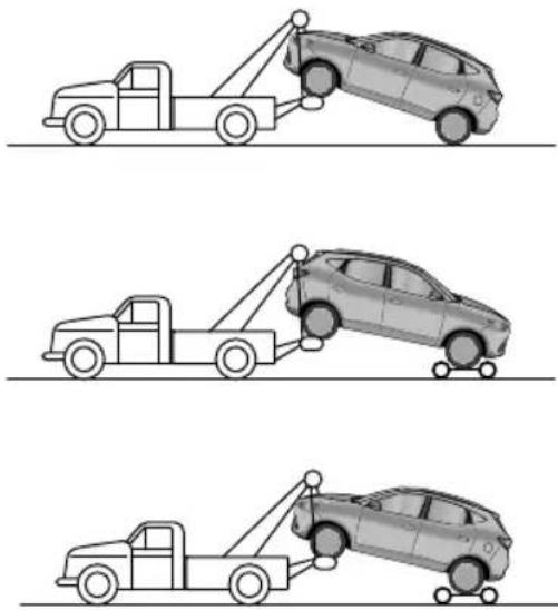
Four-WheelTouchdownT owing
If vehicleistowed with the four wheels on the ground, observ the following precautions:
ISwitchtheSTART/STOPSwitchtothe ON/RUNNINGpositiontoenablethebrakelights, wipersanddirectionindicatorstobeoperatedif necessary.If,duetoanelectricalfault,itisconsidered unsafetoswitchtheSTART/STOPSwitchon,thecar willneedtoberecoveredonatrailer.
2PlacetheshiftleverinNposition(manual transmission), orinNposition(automatic transmission).
3Releasetheparkingbrake.
4T urnonthehazardwarninglamps.
the transmission damaged back of lubricating oil, DONOT tow the vehicle with four wheels on the ground.
BONO Towackward/withron wheels(drive wheels)on the ground.
EMERGENCYINFORMATION

natural_image
Side view line drawing of a pickup truck and a car, no text or symbols presentWithout the engineer running, greater effort will be required to operate the brake pedaland turn the steering wheel. Longer stopping distances will also be experienced.
T ransporterorTrailerwithRope
If your caristobetransported on the back of a trailer or transporter, it must be secured as illustrated:
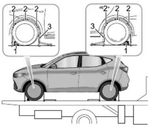
text_image
Diagram of a car under load with labeled parts and structural diagrams showing mechanical components.IPositionthecaronthetrailer, apply the parking brake, and placetheshift lever in N position (manual transmission), or in P position (automatic transmission).
EMERGENCYINFORMATION
2Placethewheelchock(1)asshowninthefigure, thenplacetheantisliprubberpad(2)aroundthe circumferenceofthetyre.
3Fitthelashingstraps(3)aroundthewheelsandsecure tothetrailer.Tightenthestrapsuntilthecaris securelyheld.
EMERGENCYINFORMATION
T yreRepairandWheelReplacement
T oolldentification
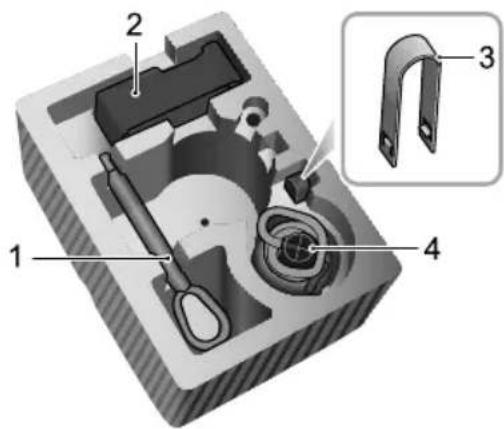
text_image
Technical diagram of a mechanical component with numbered parts and an inset view labeled 3IT owingHook
2ElectricAirPump
3WheelBoltCapRemovalTool
4RepairFluidReservoir
T yreRepair
I Removethelabelatthebottomoftherepairfluid reservoirandattachittothesteeringwheeltoremind thedrivernottoexceed50mph(80km/h).
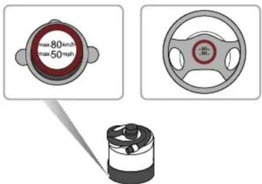
text_image
max 80 km/h max 50 mph -60- -50-2Connecttheairhoseoftheelectricairpumpto therepairfluidreservoir,fitthetyresealantbottle (upright)intotheslotonthecompressor.Remove thevalvedustcapoftheflattyre,andconnectthe fillerhosefromthetyresealantbottletothetyre
EMERGENCYINFORMATION
valve.Ensurethatthepowerswitchoftheelectric aircompressorisswitchedoff(i.e.,press“O”),then inserttheplugfromthecompressorintothecentre consolepowersocket,andturntheSTART/STOP Switchtotheposition"ON/RUNNING".
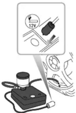
text_image
Diagram illustrating a mechanical testing setup with labeled components and directional arrows indicating motion or force.Note: To avoid battery discharge, it is recommended to keep the engineer running.
Switch the powers switch of the electric compressor (i.e., press “-”), to start pumping sealant into the tyre. Thetyresealant bottle will become empty after approximately 30 seconds. Thetyreshould reach the specified pressure within 5 or 10 minutes.
Not the pressure gaugemaybrieflyreach 6 bar(87 psi), thenthe pressure beginstodropto normal.
4Whentherequiredpressureisreached,switchoffthe powerswitchoftheelectriccompressor(i.e.,press "O").
No if required pressure can be reached within 10 minutes, pleased disconnect the compressor, drivethe vehicle 10 metres (33 feet) approx forwardor backward to allow these sealant to spread with in thetyre. If there required pressure cast it is reached by severely damaged and you should seek assistance from the MGA authorised Repairer.
EMERGENCYINFORMATION
Note: Consecutive operation of Electric air compressor for more than 10 minutes may result in damaggetothecompressor.
Note: Undernocircumstances should you continue your journey with a deflated tyre. Driving vehicle with a deflated tyre is extremely dangerous.
5Removethetyresealantbottlefromtheslotinthe compressor, disconnect thehosefromthetyrevalve, removethecompressorplugfromthecentreconsole powersocket, returnthetyrerepairkittoitsstowage tray.
6Aftersuccessfullyaddingsealanttothetyre,drive immediatelyforashorttime(aroundoneminute)this willallowthesealanttodistributeevenlyinsidethe tyre.Continuedrivinganddonotexceed50mph(80 km/h).Afterafurther 10minutes,findasafeplaceto stopandrecheckthetyrepressure.
Pleasetakedifferentmeasuresbasedonthetyrepressure measured:
- Ifthetyrepressurehasdroppedtolessthan0.8bar (11.6sid) notontinu drivingeekssistance instead.
- Ifthetyrepressureisbetween0.8bar(11.6psi)and specified pressure, pnneathoseflectric air pumptothetyrevalve, and connecttheplugof the electricairpumptothepowersocket, thenswitchon the electricairpumptoinflatethetyreuntilreaches the specified pressure. Repeat the operationsofstep6 afterdrivinga maximumdistanceof3miles(5km).
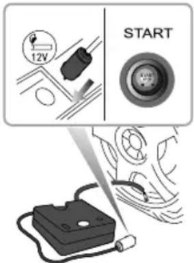
text_image
12V STARTEMERGENCYINFORMATION
- Ifthetyrepressurehasnotdropped,youmaycontinue driving,butthevehiclespeedmustnotexceed50MPH (80km/h),andthedrivingmileagemustnotexceed125 miles(200km).
Note: DONOTremoveforeignobjects(eg. screws, nails) from the theyre. Thetyrerepair system must only be used when the foreign object is in the tread pattern(A), DONOT attempt are pair when the damage is in the sidewall of the theyre(B).
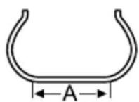
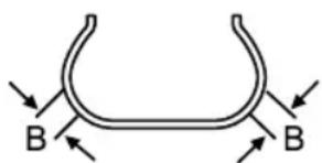
text_image
B BChangingaWheel \*
If you need to chan get the wheeld during the journey, choose as afe placet ostop away from themain road if possible. Always ask your passenger stoget out of the car and wait in as afe area away from other traffic.
Switchonhazardwarninglamps. If available position awarning triangle about 50 to 150 metres behind your vehicle towarnapproaching traffic.
Beforechangingawheel,ensurethefrontwheelsareinthe straightaheadposition.Applytheparkingbrakeandplace thegearshiftleveroftransmissioninNposition.
Observethefollowingprecautions:
- Ensurethejackispositionedonfirm,levelground.
- If the vehicle must be parked on the hill, placechocks in front of and behind other 3 wheel stop prevent the vehicle moving.
PositioningtheJack

NEVERworkbeneaththecarwiththejack astheonlymeansofsupportThejackis designedforwheelchangingonly!
EMERGENCYINFORMATION

NEVERjackthecarusinganyjackingpoints otherthanthejackingpoints.Serious damagetothecarcouldresult.
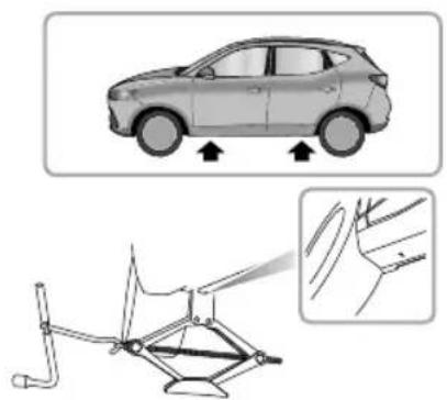
natural_image
Diagram showing a car with directional arrows and a mechanical component outline (no text or symbols)
Avoidaccidentalcontactwithanyunderbody parts,especiallyhotexhaustsystem components.
Positionthejackonfirmlevelgroundunderthejacking pointnearestthewheeltoberemoved. Notethatthe
domedheadofthejackmustfitintothecorresponding recessinthesillplate(Thereisatriangleindicatorinthe areashownbythearrowhead.Seetheillustrationabove).
T urningthejackscrewbyhand,adjustthejackuntilthejack headfitssnuglyontothesillinthecorrectarea.Ensurethat thebaseofthejackisinfullcontactwiththelevelground.
FittingtheSpareWheel

Regularly check the desire pressurism may not be used for long period softim after fitment the first opportunity the adjustment pressure.

The heddoltnushtightened the specified torqueafterchangingawheel (120 ≈ 130Nm).
Before aising hear use the special to supplied with the vehicle to remove each wheel bolt cap. Use the wheel bolt spannertoslackeneach bol thalfaturn anti-clockwise.
EMERGENCYINFORMATION
2T urnthehandleinaclockwisedirectionuntilthetyre isclearoftheground.
3Removethewheelboltsandplacetheminthetooltray topreventthemfrombeinglost.Makesurethevehicle issteadyandthereisnoriskofslipormovement beforeremovingwheelbolts.
4Removetheroadwheel.
Note: Avoidplacingwheelsfacedownonthe ground-thesurfacemaybescratched.
5Fitthesparewheelandtightenthewheelboltswith wheelboltspanneruntilthewheelisseatedfirmly againstthehub.
6Lowerthecarandremovethejack, thenFULLYtighten thewheelboltsinadiagonalsequence.
7Finally, return the tool to the toolbox, put the toolbox into the well of the boot floor, tightenthespare wheel retaining nuts, and put there placed wheel above the toolbox in the well in the load space floor (facedown). Lower the boot floor, and put the boot storage box on the boot floor.
Note: DONOTstandonthehandleofthewheelbolt spanneroruseextensiontubeonthehandleofthe spanner.
Note: When replacing the wheel, please fully tighten the bolts in the diagonal sequence twice.
Note: ConsultyourMGAuthorisedRepairerortyre specialistforareplacementtyre, as soon as possible.
SpacesaverSpareWheel

Onlyonespacesaversparewheelcanbeused atanyonetime,otherwisetheoperational performanceandbrakeperformancemaybe reduced,therebyleadingtoaccidentorinjury toyourselfandothers.

Whendrivingonicyorslipperysurfacesitis advisedtofitthespacesaverwheeltotherear ofthevehicletomaintinadaquatestability. Thismaymeanswappingafrontwheelwith arearwheel.
EMERGENCYINFORMATION

Snowchains cannot be used on the spacesaversparewheel, this can cause damage to the car and snow chain.
Whenthespacesaversparewheelisfitted,thevehicle speedshouldnotexceed50mph(80km/h).Pleasehave thefull-scaletyrerepairedandreplacethesparewheelas soonaspossible.Thiswillextendthelifespanofthespare wheelforotheremergencies.
Note: DONOTuseanautomaticcarwashwhen thespacesaverwheelisfitted, theguiderailsofthe carwashmayconflictwiththewheel/tyreandcause damage.
EMERGENCYINFORMATION
FuseReplacement
Fuse
Fusesaresimplecircuitbreakerswhichprotectthevehicle electricalequipmentbypreventingtheelectricalcircuits frombeingoverloaded.Ablownfuseindicatesthatthe itemofelectricalequipmentitprotectsstopsworking.
Checkasuspectfusebyremovingitfromthefuseboxand lookingforabreakinthewireinsidethefuse.
It is recommended to have spare functions in the vehicle, which can be obtained from a local MGA authorised repairer.
IMPORTANT
- NEVERattempttorepairablownfuse.ALWA YS replaceafusewithoneofthesamerating.
- Ifareplacedfusefailsimmediately,pleasecontactan MGAuthorisedRepairerassoonaspossible.
FuseBox
Therearetwofuseboxesinthevehicle :
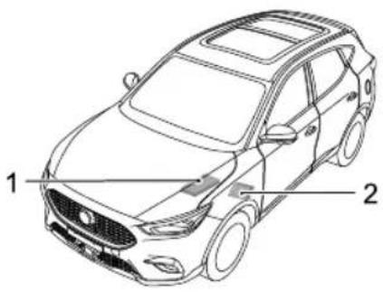
text_image
1 2IFrontCompartmentFuseBox (attheleftsideofthe FrontBay).
2PassengerCompartmentFuseBox (belowtheglove boxatthefrontpassengerside).
EMERGENCYINFORMATION
PassengerCompartmentFuseBox
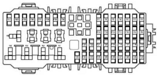
text_image
Technical diagram of a vehicle rear panel with labeled components and layout indicatorsCheckorReplaceaFuse
I Switchoffthevehiclepowersystemandallelectrical equipment, disconnectthebatterynegativecable.
2Removetheclosingpanelbelowthegloveboxtogain accesstothefusebox.
3Pressthefuseextractiontoolontothefusehead andpulltoremovethefuse.Ablownfusecanbe recognisedbyabreakinthewire.
4Replacetheblownfusewithasamerating.
FuseSpecification
| SpNkG. | Function | |
| F1 | 15A | FrontWasheRelay,Rear WasherRelay |
| D0Agn62ticSocket | ||
| 5A F3 | PRNDDisplay | |
| F0AntEdftSeat | HeatingRelay | |
| F5 | A0Aag | ECU(SDM) |
| 10A F6 | KeylesStart/StopSwitch, Gateway | |
| F7 | B0Aver | SeatAdjustSwitch |
| $5AperE8ckRelay | ||
EMERGENCYINFORMATION
| NO.Specs | Function | |
| F9-F11 | - | - |
| F125A | LeftRearDrivingAssistance Radar | |
| F13-F14 | - | - |
| F15 | 15AFrontPowerSocket | |
| F165A | FrontCourtesyLamp,Outside MirrorandMasterLightHeight AdjustSwitch,T opUSB,Left HeadlampAssembly,Right HeadlampAssembly | |
| F17 | 5ARearUSB | |
| F185AEPBSwitch | ||
| F195A | OutsideMirrorandMaster LightHeightAdjustSwitch,Rain LightSensor | |
| F2010AFrontRightSeatHeatingRelay | ||
| NO.Specs | Function | |
| F2110A | 360°ViewModule,Passenger CompartmentFuseF12 | |
| F2210A | ExteriorMirrorsHeating Element | |
| F2325A | RearWindscreenHeating Element | |
| F2420A | FrontCentralDisplay,Front InfotainmentControlModule | |
| F2510A | ElectronicT emperature Controller | |
| F265A | InstrumentPack | |
| F2710A | T ransmissionControl Module-AT | |
| F285AInformationFaceplate | ||
| F2930ASunroof | ||
| F305ADABModule | ||
EMERGENCYINFORMATION
| NO.Specs | Function | |
| F315A | T yrePressureMonitoring System | |
| F3210A | ElectronicSteeringColumn Lock | |
| F3330ASunroof | ||
| F34-F41 | -- | |
| F4225A | StabilityControl Module(Valve)-MT | |
| F4240A | StabilityControl Module(Valve)-AT | |
| F4330A | PassengerWindowliftSwitch, RearLeftWindowLiftSwitch | |
| F4430A | DriverDoorSwitchPack, DriverWindowLifter ,Rear RightWindowLiftSwitch | |
EMERGENCYINFORMATION
FrontCompartmentFuseBox
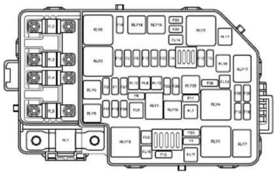
text_image
Diagram of an internal combustion engine fuse box with labeled components and terminal numbersCheckorReplaceaFuse
Switch of vehicle power system and electrical equipment disconnect battery negative cable.
Presstdocating lipotremovechusboxid.
Presheusextractionpointtheushead and puttoemovehuselowfuseabe recognized byrealithovire.
Replacehousewithamcrating.
FuseSpecification
| SpGs | Function | |
| FLI | 150Aernator | |
| 80Ful2PowesteeringModule | ||
| 40Ful3FarRelayPack | ||
| 80FL4 | Windscreen/MirrorHeatingRelay, PassengerCompartmentFuseF18, F19F20F2IF42F43F44 | |
EMERGENCYINFORMATION
| NO.Specs | Function | |
| FL5 | 80A | KLRRelay,Passenger CompartmentFuseF1,F2, F3,F4,F5,F6,F7,F8,F24,F25, F26,F27,F28,F29,F30,F31,F32, F33 |
| FL6 | - | - |
| FL7 | 40A | ElectronicT emperature Controller ,Blower |
| FL820 | ABodyControlModule | |
| FL940 | AStabilityControlModule(Pump) | |
| FL10 | - | - |
| FL11 | - | - |
| FL12 | - | - |
| FL1330 | AStarterRelay | |
| FL14 | - | - |
| NO.Specs | Function | |
| FL15 | - | - |
| FL1630 | ADC/DC | Convertor |
| FL17 | - | - |
| FI | 10ARightHeadlampAssembly | |
| F215A | DownstreamLambdaSensor,UpstreamLambdaSensor,PositiveT emperatureCoefficient(1.5L),IntakeVariableCamshaftTiming(1.0T),ExhaustVariableCamshaftTiming(1.0T),OilControlValve(1.0T),CanisterPurgeValve(1.0T) | |
| F310A | LeftHeadlampAssembly | |
| F410A | CompressorRelay | |
| F5 | 5AEngineControlModule | |
| F610A | FuellInjector(1.5L) | |
EMERGENCYINFORMATION
| NO.Specs | Function | |
| F7 | 30A | FrontWiperEnableRelay,Front WiperHigh/LowSpeedRelay |
| 5A F8 | CoolingFanRelayPack,Brake PedalSwitch,FuelPumpRelay, ACPressureSwitch,Neutral Switch(1.5L) | |
| F920A | FuelPumpRelay | |
| F1010A | RightHeadlampAssembly | |
| F11 | 10ALeftHeadlampAssembly | |
| F1230A | IgnitionCoil,EngineControl Module | |
| F1315A | HornRelay | |
| F14 | - | - |
| NO.Specs | Function | |
| F15 | 10A | IntakeVariableCamshaftTiming(1.5L),ExhaustVariableCamshaftTiming(1.5L),CanisterPurgeValve(1.5L),ElectronicThermostat(1.0T),ElectronicWaterPump(1.0T),DumpValve(1.0T),WasteGateControlValve(1.0T),ClutchMasterCylinderSensor(1.0T) |
| F1615A | RearWiperRelay | |
| F17 | 10A | FogLampRelay |
| F185AAirbagECU(SDM) | ||
| F195A | InstrumentPack,FrontDetectRadar,FrontViewControlModule,ShifterMechanism,ReverseLampSwitch,DC/DCConvertor,AirbagDisplayModule | |
| F205A | EngineControlModule | |
EMERGENCYINFORMATION
| NO.Specs | Function | |
| F2125A | BodyControlModule | |
| F22 | - | - |
| F23 | - | - |
| F24 | - | - |
| F2530A | BodyControlModule | |
| F26 | - | - |
| F2715A | BodyControlModule | |
| F28 | - | - |
| F29 | - | - |
| F305A | EngineControlModule | |
EMERGENCYINFORMATION
BulbReplacement
BulbSpecification
| LampBulb | Specifications |
| HeadlampHigh/Low Beam | LED |
| FrontDirection Indicators | LED |
| DaytimeRunningLampsLED | |
| FrontSideLight | LED |
| FrontFogLamps * | H835W |
| ReverseLamps | W16W16W |
| RearDirectionIndicators | WY16W16W |
| LampBulb | Specifications |
| RearSideLight | LED |
| StopLamps | LED |
| LicensePlateLampsW5W5W | |
| RearFogLampsLED | |
| HighMountedStopLamp | LED |
| InteriorLampW5W5W | |
| LoadSpaceLampC10W10W |
EMERGENCYINFORMATION
BulbReplacement
Beforereplacinganybulb,turnoffthelightingswitchto avoidanypossibilityofashortcircuit.
Note: MGonly recommends replacement bulbsthat completely meet them manufacturer specifications.
Take care NOT to touch the glass with your fingers; always use a cloth to handle the bulb. If necessary, clean the glass with methylated spirit to remove fingerprints.
Ifindoubt,whenreplacingbulbs,contactanMG AuthorisedRepairer.
Forreplacementofotherbulbsnotlistedpleaseconsultan MGAuthorisedRepairer .
FrontFogLampsBulbRenewal
I Disconnect the battery negative terminal.
2Forfrontfoglampsbulbreplacement,itisnecessary toremovethefrontbumpercover,seekguidancefrom anAuthorisedMGRepairer.
3Removethewiringconnectorfromthebulb.
4Rotatethebulbanti-clockwiseandremove.
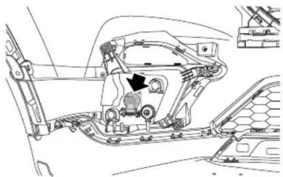
natural_image
Technical line drawing of a vehicle's internal components, including suspension parts and a highlighted valve (no text or labels)EMERGENCYINFORMATION
5Locatethebulbinthelamp, rotateclockwiseuntilfully secured.
6Refitthewiringconnectortothenewbulb.
7Fitthefrontbumpercover.
8Connectthenegativebatteryterminal.
9T estlampoperation.
ReverseLampsBulbRenewal
I Openthetailgate.
2Disconnectthebatterynegativeterminal.
3Usingasuitableprybarorlever,carefullyremovethe covertrim.
4Usingasuitablespanner/socketwrench,removethe3 screws(1)securingthelamptothetailgate.Remove the wiringconnector(2).Releasethelampassembly andremoveawayfromthebody.
EMERGENCYINFORMATION
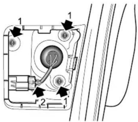
text_image
Technical diagram of a device with labeled parts and directional arrows indicating assembly or connection points.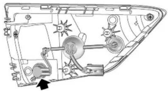
natural_image
Technical diagram of a vehicle's internal components, showing hoses, wheels, and wiring (no text or labels)5Rotatethebulbholderinananti-clockwisedirection.6Removebulbholderandremovebulb.
7Fitnewbulbtobulbholder.
8Insertbulbholderinlampassembly, rotateclockwise untilfullysecure.
9Ensurelampsealiscorrectlylocated.
10Positionlamptotailgate, refitthewiringconnector andthescrewfixings, andtightento2.7-3.3Nm.
EMERGENCYINFORMATION
I I Refitscrewcovertrim.
12Reconnectbatterynegativeterminal.
13T estlampoperation.
14Closetailgate.
LicensePlateLampsBulbRenewal
I Disconnect the battery negative terminal.
2Forlicenseplatelampsbulbreplacement,itis necessarytoremovetherearbumpercover ,seek guidancefromanAuthorisedMGRepairer.
3Removethewiringconnector.
4Rotatethebulbholderinananti-clockwisedirection.
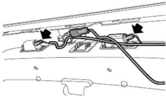
natural_image
Diagram of a mechanical or electrical component with wires and connectors, no visible text or symbolsEMERGENCYINFORMATION
5Removebulbholderandremovebulb.
6Fitnewbulbtobulbholder.
7Insertbulbholderinlampassembly, rotateclockwise untilfullysecure.
8Refitthewiringconnector.
9Fittherearbumpercover.
10Reconnectbatterynegativeterminal.
IIT estlampoperation.
RearDirectionIndicatorBulbRenewal
1 Openthetailgate.
2Disconnectthebatterynegativeterminal.
3Usingasuitableprybarorlever,carefullyreleaseand removethesecuringscrewcovertrim.
4Usingasuitablespanner/socketwrench,removethe2 screwssecuringthelamptothebody.
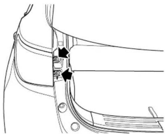
natural_image
Technical line drawing of a mechanical component with two black arrows indicating specific features (no text or symbols present)EMERGENCYINFORMATION
5Removethewiringconnector.Releasethelamp assemblyandremoveawayfromthebody.
6Rotatethebulbholderinananti-clockwisedirection.
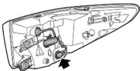
natural_image
Technical line drawing of a mechanical device interior with no visible text or symbols7Removebulbholderandremovebulb.
8Fitnewbulbtobulbholder.
9Insertbulbholderinlampassembly, rotateclockwise untilfullysecure.
10 Ensure lampseal is correctly located.
11Positionlamptobody, refitthewiringconnector, start bothscrewfixings, and tightento3-5Nm.
12Refitscrewcovertrim.
I3Reconnectbatterynegativeterminal.
14T estlampoperation.
15Closetailgate.
EMERGENCYINFORMATION
InteriorLampBulbRenewal
I Disconnect the batterynegativeterminal.
2Useasuitabletoolorsmallflatbladedscrewdriverto gentlyprisefrontendofthelens,andremovethelens.
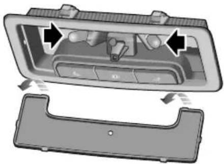
natural_image
Interior view of a car dashboard with control panel and rear door (no text or symbols visible)assembly.Pushthelensupwardsuntil‘clicks’into position
6Connectbatterynegativeterminal.
7T estlampoperation.
3Pullthebulbfromitsmountingtoremove.
4Installnewbulb.
5Installthelens,locatethetwoprongsatthefront ofthelensandthencarefullyflexthelenstolocate thetwoprongsattherearofthelensintothelamp
EMERGENCYINFORMATION
LoadSpaceLampBulbRenewal
1 Openthetailgate.
2Disconnectthebatterynegativeterminal.
3Insertasuitabletoolorsmallflatbladedscrewdriver intotheindentononeofthenarrowsidesofthelens andcarefullyremovetheunitfromitslocation.
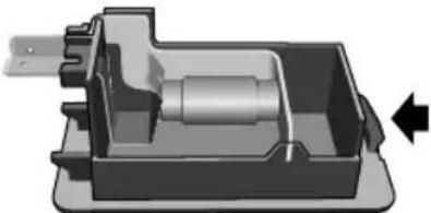
natural_image
3D mechanical assembly diagram showing internal components with a directional arrow (no text or symbols)4Pullthebulbfromitsmountingtoremove.
5Installnewbulb.
6Refittheunit, pushuntilfullysecured.
7Connectbatterynegativeterminal.
8T estlampoperation.
9Closetailgate.
Maintenance
260Maintenance
264Bonnet
266 EngineCompartment
268Engine
270CoolingSystem
272 Brake
274Battery
276 Washers
278Wipers
281 Tyres
287CleaningandVehicleCare
MAINTENANCE
Maintenance
RoutineMaintenance
Thesafety, reliability and performance of your car will depend partly on how well it is maintained. You must ensure that maintenance is carried out when required and according to the information contained in the 'Service Schedule'.
Servicing
Fornextserviceinformation, pleasereferto "Message Centre" in "InstrumentsandControls" chapteror informationrelatedtoentertainmentsystem. After the completionofeachservice, thenextservicedisplaywill beresetbyyourMGAuthorisedRepairer.
Note: If a service is not carried out (orth display is not reset by the local MGA authorised Repairer after service), the serviced display cannot provide correct information.
ServiceHistory
EnsureyourlocalMGAuthorisedRepairerfillsinthe ServiceRecordsaftereachservice.
BrakeFluidReplacement
Replace the fluid according to information contained in the "ServiceSchedule".
Note Brakefluidreplacementwillbeanadditional cost.
CoolantReplacement
Replacetheenginecoolant(mixedsolutionofantifreeze andwater)accordingtotheinformationcontainedinthe "ServiceSchedule".
Note: Coolantreplacementwillbeanadditionalcost.
EmissionControl
Y ourcarisfittedwithemissionandevaporativecontrol equipmentdesignedtomeetspecificterritorialandlegal requirementscorrectenginesettingsmayadversely affectexhaustemissionsengineperformanceandfuel
consumption, as well as causing hight temperatures, which could result in damagethe catalytic converters and engine.
IMPORTANT
Y oushouldbeawarethatunauthorisedreplacement, modificationortamperingwiththisequipmentbyan ownerormotorvehiclerepairercouldresultinthe manufacturer'swarrantybeingdeemedasinvalid.In addition,enginesettingsmustnotbetamperedwith.
OwnerMaintenance

Anysignificantorsuddendropinfluidlevels, oruneventyrewear,shouldbereported withoutdelay.Forfurtherinformation,refer toanMGAuthorisedRepairer.
Inadditiontotheroutineservicesreferredtoppreviously, anumberofsimplechecksmustbecarriedoutmore frequently. Youcancarryoutthesechecksyourselfand adviceisgivenonthepagesthatfollow.
DailyChecks
•Operationoflights,horn,directionindicators,wipers, washersandwarninglights.
•Operationofseatbeltsandbrakes.
- Lookforfluiddepositsunderneaththecarthatmight indicatealeak.
- Checktyreappearance.
WeeklyCheck
- Engineoillevel.
- Coolantlevel.
- Brakefluidlevel.
•Windscreenwasherfluidlevel. - Operateairconditioning.
Note: The engine oil level should be checked more frequently if the car is driven for prolonged periods at high speeds.
SpecialOperatingConditions
yours equentlyseilustyondition or operatediextremeclimateswheresub-zeroory highambienttemperaturesarenormal, morefrequent attentionmayneedtobepaidtoservicingrequirements.
MAINTENANCE
Y ouneedtocarryoutspecialmaintenanceoperations (refertoServicePortfolioorcontactyourMGAuthorised Repairer).
SafetyintheGarage

Coolingfansmaycommenceoperatingafter theengineisswitchedoff,andcontinue operatingforanumberofminutes.Keep clearofallfanswhileworkingintheengine compartment.
If you need to carry out maintenance, observe the following safety precautions at all times:
- Keepyourhandsandclothingawayfromdrivebeltsand pulleys.
- If the car has been driven recently, DONOTTOUCH exhaust and cooling system components until the engine has cooled.
DONOTOUCH-electrical lead components while the engine is running, or with the ignition switch on.
- NEVERleavetheengine running in an unventilated area -exhaust gases are poisonous and extremely dangerous.
DONOWorknderneattheawidwheel changingjackastheonlymeansofsupport.
- Ensurethatsparksandnakedlightsarefarawayfrom theenginecompartment.
- Wearprotectiveclothingandworkgloves.
- Removewatchesandjewelrybeforeworkinginthe enginecompartment.
- DONOTallowtoolsormetalpartsofthecartomake contactwiththebatteryleadsorterminals.
ToxicLiquid
Fluidsusedinmotorvehiclesarepoisonousandshouldnot beconsumedorbroughtintocontactwithopenwounds. These include battery, acid, coolantbrak, fluidpower steering fluid, engine and windscreewasher additives.
FoyouwwsafetALWAYiSeachobservall instructionsprintedonlabelsandcontainers.
MAINTENANCE
UsedEngineOil
Prolongedcontactwithengineoilmaycauseseriousskin disorders,includingdermatitisandcanceroftheskin.
Washthoroughlyaftercontact.Usedengineoilshould bedisposedofcorrectly.Incorrectdisposalcancausea threattotheenvironment.
MAINTENANCE
Bonnet
OpeningtheBonnet

DONOTdrivewhenthebonnetisnotclosed orretainedonlybythesafetycatch.
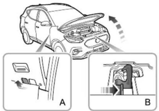
text_image
Diagram illustrating car engine compartment changes, showing structural change and component insertion steps labeled A and B.I From the inside of the vehicle, pull the bonnet release handle (Figure A).
2Movethesafetycatchreleasehandleonthebonnet lockassemblyinthedirectionofthearrow(FigureB) toreleasethebonnetsafetycatch.
3Raisethebonnetandholditupwiththesupportrod firmly.
ClosingtheBonnet
Supportthebonnetbyonehand, releasethesupportrod usingtheotherhand, and placeitfirmlyintothesupport rodbase. Thenholdthebonnetusingbothhandsand lowerit, allowingittodropforthelast20cm \~ 30cm tofullyclosethebonnet.
Byattemptingtoliftthefrontedgeofthebonnet,checkif thelockisfullyengagedafterclosingthebonnet.lfitisnot fullyengaged,youmustrepeattheoperation.
BonnetOpenWarning
Ifthebonnetisnotfullyengaged,whenthevehicle powersystemisintheON/RUNNINGposition,the
correspondingalarmiconwillbedisplayedinthe informationmessagecentreoftheinstrumentpack.If itisdetectedthatthebonnetisnotfullyengagedwhilst driving,anaudiblewarningwillsound.
IMPORTANT
- Forsafetyreasons,thebonnetshouldbefullylatched andsecurewhendriving.Thereforeeverytimethe bonnetisopened,youmustcheckafterclosingthat thebonnetissecurelylatched,e.g.thebonnetedge isflushwiththebodyofthecar .
• Y oushouldstopthecarimmediatelywhensafety permitsandclosethebonnetifitisnotclosedfully whendriving. - Ensurethebonnetissupportedmanuallywhen removingthebonnetsupportrod,failuretosupport thepanelwillresultinthepanelfallingdowncausing injuryvehicledamage.
Bewareifjurybandwhilelosingthe bonnetwithadownwardforce.
MAINTENANCE
EngineCompartment
1.5LEngineCompartment

While working in the engine compartment, always observethes safety precautions listed under 'Safety in the Garage', referto 'Maintenance' in 'Maintenance' section.
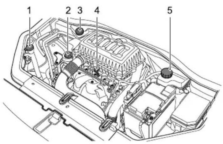
text_image
1 2 3 4 5I Washerfluidreservoir(bluecap)
2Engineoilfillercap(blackcap)
3Brakefluidreservoir(yellowcap)
4Engineoildipstick(yellow)
5Coolantreservoir(blackcap)
1.0LT urbochargedEngineCompartment

While working in the engine compartment, always observethes safety precautions listed under 'Safety in the Garage', refer to 'Maintenance' in 'Maintenance' section.
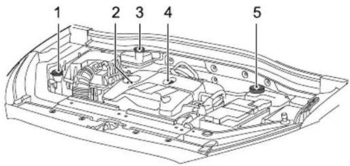
text_image
1 2 3 4 5I Washerfluidreservoir(bluecap)
2Engineoilfillercap(blackcap)
3Brakefluidreservoir(yellowcap)
4Engineoildipstick(yellow)
5Coolantreservoir(blackcap)
MAINTENANCE
Engine
EngineOil
ACEAClassificationofEngineOils
EuropeanAutomobileManufacturersAssociation(ACEA) will classify the engine oils based on performance and quality. T oensure the best performance of the vehicle, please only use engine oil that a rerecommended by the manufacturer (see "T echnical Data" - 'Recommended Fluids and Capacities'.
If you are operating the vehicle in extreme temperature conditions please consult your MGA authorised Repairer for advice.
EngineOilLevelCheckandT opUp

Drivingthevehiclewiththeengineoillevel ABOVEtheuppermark,orBELOWthelower markonthedipstick,willdamagetheengine. T akecaretoavoidspillingengineoilontoa hotengine-afiremayresult!
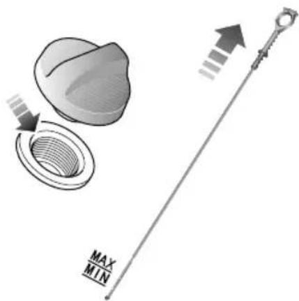
text_image
MAX MIN1.5LEngine
MAINTENANCE
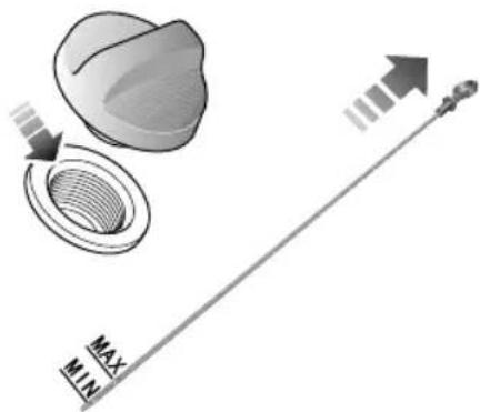
text_image
MAX MIN1.0TEngine
Checktheoillevelweeklyandtopupwithoilwhen necessary.Ideally,theoillevelshouldbecheckedwiththe enginecoldandthecarrestingonlevelground.However, iftheengineisrunningandalreadygettingwarm,waitfor atleastfiveminutesafterswitchingofftheSTART/STOP Switchbeforecheckingthelevel.
I Withdrawthedipstickandwipethebladeclean.
2Slowlyinserttheoildipstickandpullitoutagainto checktheoillevel;theoillevelshallnotbelowerthan the"MIN"markontheoildipstick.
3Cleanoffanydebristhatmayhavecollectedaround theoilfillercaparea.Unscrewtheoilfillercapand refilltheoiltomaintaintheoillevelbetween the "MAX" markand"MIN" markontheoildipstick.
4Waitfor5minutesandthenrechecktheoillevel, addingmoreoilifnecessary-DONOTOVERFILL!
5Finally,ensurethedipstickandfillercaparereplaced.
EngineOilSpecification
Usetheengineoilrecommendedandcertifiedbythe manufacturer .Referto"RecommendedFluidsand Capacities"in"T echnicalData"section.
Note: DONOTuseanyoiladditives.
IMPORTANT
Checktheengineoilmorefrequentlyifthevehicleis drivenathighspeedsforprolongedperiods.
MAINTENANCE
CoolingSystem
CoolantCheckandT opUp

DONOTremovetheenginecoolantreservoir capwhenthecoolingsystemishot-escaping steamorhotcoolantcouldcauseserious injury.
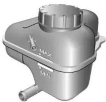
natural_image
3D rendered image of a mechanical component with MAX and MIN labels (no readable text or symbols beyond basic markings)It is recommended that the coolingsystem should be checked weekly when the coolingsystem is cold and with the arresting on level ground. If the level is below the 'MIN' mark, removal the expansion tank cap and top up coolant, the level must not be higher than 'MAX' mark.
Note: Preventcoolantcomingintocontactwiththe vehiclebodywhentoppingup.Coolantwilldamage paint.
If the coolant level falls appreciably during short period, the cooling system leakagemay occur, please have its serviced time by a local MGA authorised Repairer.
CoolantSpecification
Pleaseusethecoolantrecommendedandcertifiedby themanufacturer .Referto'RecommendedFluidsand Capacities'in"TechnicalData"chapter.
Note: In an emergency, to pup the coolant reservoir with a small amount of clean water. However, it should be noted that this will weaken the anti-freeze and anti-corrosion protection and reduce the service life
of the coolant. DONOTrefill the coolingsystem with anti-freeze of different formulations.
Note: The addition of corrosion inhibitors or other additives the coolingsystem of this car may severely disrupt the efficiency of the system and cause engine damage. For coolingsystem issues please consult an MGA authorised Repairer.
AntifreezeFluid

Coolantispoisonousandcanbefatalif swallowed-keepcoolantcontainerssealed andoutofthereachofchildren.Ifaccidental contactofcoolantbychildrenissuspected, seekmedicalassistanceimmediately.

Preventcoolantcomingintocontactwiththe skinoreyes.Ifthisoccurs,rinseimmediately withplentyofwater.Ifeyesarestillred, painfuloruncomfortableekmedical attentionimmediately.
MAINTENANCE
Brake
BrakePads

DONOTrestyourfootonthebrakepedal whiledriving; thismayoverheatthebrakes, reducetheirefficiencyandcauseexcessive wear.
Forthefirst900miles(1500km),youshouldavoid situationswhereheavybrakingisrequired.
Remember that regular servicing is vital to ensure that all the brake components are examined for wear at the correct intervals, and replaced when required to ensure long terms safety and optimum performance during the interval prescribed in Service Portfolio.
Thecarneedstoruninfor500miles(800km)afterthe brakepadordiscisreplaced.
BrakeFluidCheckandT opUp

Brakefluidishighlytoxic, keepcontainers sealed and out of thereachofchildren. If accidental contact of brakefluidissuspected, seek medical attention immediately.

Preventbrakefluidcomingintocontact withtheskinoreyes.Ifthisoccurs,rinse immediatelywithplentyofwater.Ifeyes arestillred,painfuloruncomfortable,seek medicalattentionimmediately.
Thebrakefluidlevelshouldbecheckedweeklywhenthe systemiscoldandwiththearonlevelground.
Thefluidlevelcanbeseenthroughthereservoirneck andshouldbemaintainedasclosetothe"MAX"mark aspossibDonotallowtheleveltodropbelowthe"MIN"mark.
Note: Brakefluidwilldamagepaintedsurfaces. If you accidentally spill the brakefluid on the painted surface, soak up any spillagewith an absorbent cloth
immediately and wash the area with water or car shampoo.
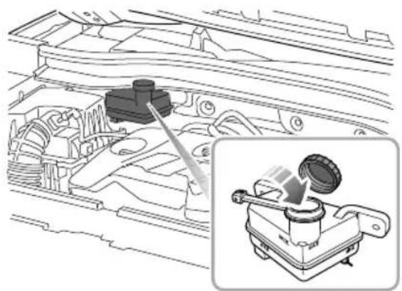
natural_image
Technical line drawing of a mechanical assembly with an inset showing a component detail (no text or symbols)IMPORTANT
ReplacebrakefluidregularlyaccordingtotheService Portfolio.
BrakeFluidSpecification
Usethebrakefluidrecommendedandapprovedby themanufacturer .Referto"RecommendedFluidsand Capacities"inthe"TechnicalData"section.
MAINTENANCE
Battery
BatteryMaintenance

DONOTleaveelectriccomponentsswitched onwhentheengineisnotrunning,the batterymaybecomeflatandyouwillnotbe abletostarttheengine.
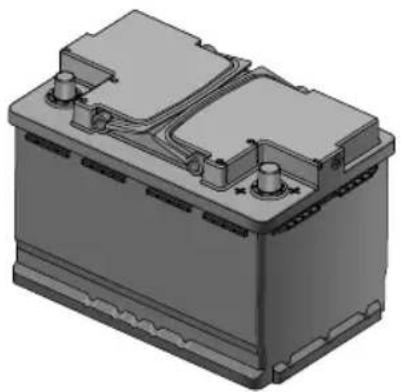
natural_image
3D rendering of a battery housing with cooling fins and mounting feet (no text or symbols visible)Y oucanseethebatterywhenyouopentheengine compartment.Thebatterysimaintenance-freetype, thereforethereisnoneedtorefillfluid.
Note: If the vehicle is stored for more than 1 month, removethenegativeterminal from the battery. Make sure that the START/STOP switch has been turned off before connecting or disconnecting then negative terminal. When connecting then negativeterminal again, the vehicle must be left in a locked state for 4 hour store-calibratethe battery condition. Failure to adher to this will inhibit the stop/start functionality.
BatteryReplacement

The battery contains sulphuric acid, which is corrosive.
The battery contains sulphuric acid, which is corrosive. Please go to an MG Authorised Repair to remove and install the battery. Only fit are replacement battery of the sametype and specification as the original to maintain the correct vehicle functionality.
MAINTENANCE

Thebatterymustbedisposedofusinganapproved method,usedbatteriescanbeharmfultotheenvironment. Itshouldberecycledbyaprofessionalcompany.Please consultanMGAuthorisedRepairerformoredetails.
MAINTENANCE
Washers
WindscreenWasherCheckandT opUp

Whenfillingthewasherfluid,DONOT letthewasherfluidspillonpartsinthe compartmentoronthepaintsurfaceof vehiclebody.Incasethewasherfluidis spilledonhandsorotherpartsofthebody, pleaseimmediatelywashwithcleanwater.
Checkthewasherfluidlevelregularly. Whenthelevel ofwasherfluidislow, pleasetopupthewasherfluidas instructed.
Note: DONOTuseanti-freezeorvinegar/water solutioninthewasherreservoir-anti-freezewill damagepaintworkwhilevinegarwilldamagethe washerpump.
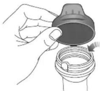
natural_image
Illustration of a hand holding a cap and a coiled hose (no text or symbols)IMPORTANT
Usethewasherfluidrecommendedandcertifiedby themanufacturer .Misuseofwasherfluidinwinter maycausedamagetothewasherpumpdueto freezing.
Using hewasherswhenthereisnowasherfluidmay causedamagetothewasherpump.
Operatingthewiperswhenthewindshieldsaredry andthereisnowasherfluidmaycausedamageto thewindshieldsandwipersPleasespraythewasher fluidandstartthewiperswhenthereisadequate washerfluid.
MAINTENANCE
WasherNozzles
Operatethewashersperiodically to check that thenozzles are clear and properly directed.
If thenozzleisobstructed, insertaneedleorthinmetal wire into the holetoremovetheobstruction.
WasherFluidSpecification
Usethewasherfluidrecommendedandcertifiedby themanufacturer .Referto'RecommendedFluidsand Capacities'.
MAINTENANCE
Wipers
WiperBlades
| IMPORTANT |
| •Grease,siliconandpetrolbasedproductsimpairtheblade'swipingcapability.Washthewiperbladesinwarmsoapy waterandperiodicallychecktheircondition. |
| •Cleanthewindscreenfrequently,DONOTusewiperstoremovestubbornoringraineddirt,itwillreducetheir effectandtheirlifespan. |
| •Ifsignsofhardnessorcrackingintherubberarefound,orifthewipersleavestreaksorunwipedareasonthescreen, thenthewiperbladesshouldbereplaced. |
| •Cleanthewindscreenregularlywithanapprovedglasscleanerandensurethescreenisthoroughlycleanedbefore fittingreplacementwiperblades. |
| •Onlyfitreplacementwiperbladesthatareidenticaltotheoriginalspecification. |
| •Cleaniceandsnowfromaroundwipersandensuretheyarenotfrozenorotherwisestickingtothewindscreen beforeattemptingtooperatethem. |
MAINTENANCE
ReplacingFrontWiperBlades
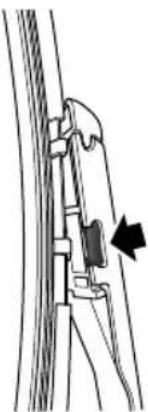
natural_image
Line drawing of a person using a tool to lift a rope, with an arrow indicating the motion direction (no text or symbols present)IWiththebonnetclosed,andwithin20seconds ofswitchingthevehiclepowersystemtotheOFF position,operatethewiperstalkswitchbypassing downandreleasing,thewiperswillsweepandstopin the'serviceposition'onthewindscreen.
2Liftthewiperarmawayfromthewindscreen.
3Presstheretainingclipsatbothsides(asshownin thefigure), whilstpullingthewiperbladeoutward, toremovethewiperbladefromthewiperarmand discard.
4Positionthefittingofthenewwiperbladeintotheslot ofthewiperarm.
5Pushthewiperbladetowardsthewiperarmuntilis locatedembeddedwithaclickbeenheard.
6Placethewiperassemblybackonthewindscreen.
7T oexittheservicemodeandreturnthewiperstothe parkposition,operatethewiperstalkswitchagainby pressingdownandreleasing,alternatively,switchthe vehiclepowersystemtotheONposition.
MAINTENANCE
ReplacingRearWiperBlades
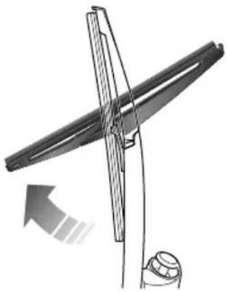
natural_image
Diagram of a mechanical device with a rotating shaft and base, showing motion direction (no text or symbols)I Liftthewiperarmawayfromtherearwindow.
2Rotatethewiperbladeasshowninthefigure,to removeitfromthewiperarmanddiscard.
3Positionthefittingofthenewwiperbladeintotheslot ofthewiperarm.Ensurethewiperbladeisproperly securedonthewiperarm.
4Placethewiperassemblybackontherearwindow.
T yres
Overview
• T akeextracarewhenusingnewtyresforthefirst300 miles(500kilometres).
- Avoidexcessivecorneringatspeed.
- Slowdownwhenpassingthroughroadshoulderora similarsection,andallowthewheelstogothroughthe shoulderattherightangleasfaraspossible.
- Regularlycheckthedamageoftyres(stabs,scratches, cracksandpits)andremoveanyforeignobjectsfrom thetread.
•Preventthetyrefromcontactingoil,greaseandfuel.
- Ensurevalvecapsarealwaysfitted.
- Ifthetyreistoberemovedalwaysmarkthetyre/wheel orientationtoensurecorrectreinstallation.
- Thewheelsortyresthathavebeendisassembledshould bekeptinacool,dryandlight-freeplace.
NewT yres
Newtyresmaynothavethebestadhesiveabilityatthe beginning. Therefore, driving your vehicle at moderate speedandinaprudentwayatthefirst300miles(500 kilometres),whichisalsobeneficialtotheservicelifeof thetyres.
Thedamageoftyreorrimmayhappenunnoticed.If abnormalvibrationorhandlingisexperienced,thatmeans theyreorrimmayhavebeendamaged.Pleaseeslowdown andparkyourvehicleinabsolutesafety,thencheckthe tyreandrim.Ifyoucan'tseethedamagefromtheoutside, youshouldcontinuetodrivewithlowspeedandgotothe nearestMGAuthorisedRepairerforinspection.
DirectionalT yres
Directionaltyresaremarkedwith'directionofrotation'(DOR).T omaintainhandlingcharacteristics,tyre performance,lowroadnoiseandextendtyrelife,tyres mustalwaysbefittedwithindicationarrowshowingthe correct'DOR'.
T yreLife
Correcttyrepressureandmoderatedrivingstylecan extendtyrelife.
Recommendations:
MAINTENANCE
- If the vehicle is restored for all lengthy time, please move your vehicle at least once in two weeks to 'rotate the tyres'.
- Check the pressure of tyres regularly when they are cold.
- Avoidcorneringatexcessivespeed.
• Regularlychecktyresforabnormalwearpatterns.
These following factors may affect the life.
T yrePressure
Incorrectpressurewillcausetheabnormalwearofthe tyre,greatlyshortentheservicelife,andhaveanadverse effectonthedrivingcharacteristicsofthevehicle.T yre pressureshouldbecheckedatleastonceamonth,and oncepriortoeachlong-distancejourney.
DrivingStyle
Excessivelyharshaccelerationandbraking (youmayhear apiercingnoise)ordrivingathighspeedwhilstcornering willincreasethewearofyre.
WheelBalance
The working balance of auto-wheels is well tested before a new vehicle comes out of the factory. But the wheels may be out of balanced duet many factors.
Ifwheelsareoutofbalance, shakingorvibrationofthe steeringmechanismmayoccurandthetyresmaybe excessivelyworn. It is important to rectify this quickly. Each wheel should be balanced after installing anewtyre or having the teryrerepair .
WheelAlignment
Incorrectwheelalignmentcancauseexcessivetyrewear and affect vehiclesafety. If the tyresshowsignsofabnormal wear, seek advice from MGA authorised Repairer.
CaringforY ourT yres

DEFECTIVETYRESAREDANGEROUS! DONO Tdriveifanytyreisdamaged, is excessivelyworn, orisinflatedtoanincorrect pressure.
Alwaysdrivewithconsiderationfortheconditionofthe tyres,andregularlyinspectthetreadandsidewallsforany signofdistortion(bulges),cutsorwear.
Note: If possible, protect tyres from contamination by oil, grease and fuel.
T yrePressure

Beforealongdistancejourney,thetyre pressuremustbechecked.
Check the pressure (including the spare wheel) at least once a month, when the yres are cold.
Ifitisnecessarytocheckthetyrepressurewhentheyare warm,youshouldexpectthepressuretohaveincreasedby 0.3to0.4bar(4.35to5.8psi).Inthiscircumstance,NEVER letairoutofthetyresinordertomatchtherecommended pressure(cold).
Valves
Keepthevalvecapsscreweddownfirmly-thypreventdirt fromenteringthevalve.Checkthevalveforleaks(listen foratell-talehissing)whenyoucheckthetyrepressure.
PuncturedT yres
lfasharpobjectpenetratesthetyreandremainsinit,the tyremaynotleak.Ifyouareawareofthisoccurring,reduce speedimmediatelyanddrivewithcautionuntilthespare wheelcanbefitted,orrepairsundertaken.
Note: If the sidewallofthetyreisdamagedor distorted, plaatyinmediatelpot attemptarepair.
T yreWearIndicators
Atthebottomoftheoriginaltyre,thereisa1.6millimeter higheanarperpendiculabheebilling direction.Theseindicatorsmouldedintothetreadpattern atseveralpointsaroundthecircumferenceAmarkon thesideofatyre,suchastheuppercaseletterTWlor thetriangle,indicatingthepositionofthewearmark.
Whether a word down 6 millimeter the indicators will cometothesurface of the tread pattern, producing the effect of a continuous band of rubber across the width of the tyre.
MAINTENANCE
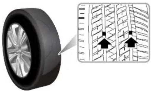
natural_image
Diagram showing a car tire and its internal road pattern with directional arrows (no text or symbols)IMPORTANT
AtyreMUSTbereplacedassoonasawearindicator becomesvisible.
ReplacementTyres

Itisrecommendedtoinstallthetyres consistentwiththeoriginalspecifications. DONOTreplacethetyreswithtyresofany othertype.Alternativetyres,ofadifferent specification,mayadverselyaffectthe vehicle'sdrivingcharacteristicsandsafety.In ordertomakeyourdrivingandsafetybetter guarantee,itissuggestedthatyouconsultan MGAuthorisedRepairer.
Alwayshavereplacementwheelsandtyresbalancedbefore use.
WheelFitmentRotation
Itisnotrecommendedthatyouswapwheelsfromside tosideorfronttorearinordertoequalisetyrewear. Y ourvehicleisfittedwithT yrePressureMonitoringSystem whichmeansthateachwheelisprogrammedtotherelative position.

flowchart
graph TD
    A["Terr 1"] --> B["Terr 2"]
    B --> C["Terr 3"]
    C --> D["Terr 4"]
    D --> A
    style A fill:#f9f,stroke:#333
    style B fill:#f9f,stroke:#333
    style C fill:#f9f,stroke:#333
    style D fill:#f9f,stroke:#333
    note1["↑"] --> A
    note2["×"] --> B
    note3["↓"] --> C
    note4["↓"] --> D
If youdowishtoswapwheelsandtyresaroundonthe vehiclepleaseconsultanMGAuthorisedRepairerasextra codingwillberequired.
SnowChains
Unsuitablesnowchainscoulddamagethetyres, wheels, suspension, brakesorbodyworkofyourcar.
Please pay attention to the following requirements in the usage:
- Thetyre/snowchainscanonlybefittedonthefront wheels;
- Thethicknessoftyre/snowchainsshallnotexceed15 mm;
- Pleasealwaysobservetheinstallationandtension instructionsforthetyre/snowchains,aswellasthe speedlimitationsofdifferentroads;
•DONOTdrivefasterthan30mph(50km/h);
•T oavoidthetyredamageandexcessivewearof thetyre/snowchains,thetyre/snowchainsmustbe removedwhiledrivingontheroadwithoutsnow.
Thewheelandtyrespecificationsforthe tyre/snowchainsapplytothismodelareas follows:
Wheelrimsize:6.5J×16
T yresize:205/60R16
Note: Snowchains are only allowed to be fitted to tyresofthespecifications recommended by the manufacturer.
MAINTENANCE
Note: If you drive on roads covered with snow orice, it is recommended to use winter tyres. Consultant MG Authorised Repairer for details.
CleaningandVehicleCare

Observeallsafetyprecautionsoncleaning products;donotdrinkfluidsandkeepthem awayfromtheeyes.
ExternalCar
WashingY ourCar

Somehighpressurecleaningsystemswill penetratedoor, windowandsunroofseals, and damagelockmechanisms. DONOTaim waterjetsdirectlyatcomponentsthatmight beeasilydamaged.

Donotcleantheenginecompartmentwith highpressurewatersinceitmaydamagethe electricalsystemofthevehicle.
Inordertopreservethepaintfinishonyourcar, please observethefollowingcarepoints:
•DONOTusehotwatertowashthecar.
•DONOTusedetergentsorwashingupliquid.
• Inhotweather, DONOT was the car indirect sunlight.
- Whenusingahose, DONOTaimthewaterdirectly atwindow, doororsunroofseals, orthroughwheel aperturesontothebrakecomponents.
Ifthecarisparticularlydirty,useahosetoflushgrimeand gritfromthebodywork,priortowashing.Then,washthe carusingcoldorlukewarmwatercontainingagoodquality washandwaxshampoo.Alwaysuseplentyofwaterto ensurethatgritisflushedfromthesurfaceandnotground intothepaintwork.Afterwashing,rinsethebodywork withcleanwateranddryoffwithachamoisleather.
Cleaningtheunderside
Note: DONOTuseahighpressurehosetocleanthe enginecompartment—damagethecar'selectronic systemsmayoccur.
Fromtimetotime, but particularly during winter months when salthas been used on other roads, use a halosetowash the underside of the car. Flush away accumulation of mud and thoroughly clean those areas where debriscane easily collect (wheel arches and panelseams, forexample).
MAINTENANCE
IMPORTANT
- Avoidcleaningthevehicleindirectsunlight.
- Whencleaningthevehicleinwinteravoidspraying waterdirectlyontodoorlocksandpanelgapsdue toriskoficing.
- Donotuseroughspongesorclothocleanthecar, thiswilldamagethepaintworkfinish.
- Whencleaningtheheadlampsdonotuseadrycloth or sponge, useonlywarmsoapywater.
CleaningwithaHighPressureCleaner
Note: Alwaysreadthemanufacturersoperating instructions.
When using high pressure washers, always ensure there is adequate distance between the spray nozzle and any soft materials, decals or rubber seals.
IMPORTANT
- Please pay attention to the operating instructions of high pressure cleaner.
- Softpartsonthevehicleshouldbekeptinalarge enoughdistancefromthehighpressurecleaner.
Removingtarspots
Usewhitespirittoremovetarspotsandstubborngrease stainsfromthepaintwork. Thenwashtheareaimmediately withsoapywatertoremovealltracesofthespirit.
BodyProtection
Afterwashing,examinethepaintworkfordamage.Ifthe damagehasrevealedbaremetal,useacoloredprimerfirst, thenapplythecorrectcolourbasecoatandfinishoffwith alacquerpencil,ifappropriate.Carryoutthistreatment afterwashingbutbeforepolishingorwaxing.More extensivedamagetopaintorbodyworkmustberepaired inaccordancewiththemanufacturer'srecommendations. FailuretodothiswillinvalidatetheAnti-Corrosion Warranty.Ifindoubt,askyourMGAuthorisedRepairer.
PolishingthePaintwork

DONOTusecarpolishcontainingcoarse abrasives—thesewillremovethepaintfilm anddamagetheglossfinish.
Occasionally treat the paints surface with an approved polish containing the following properties:
- Verymildabrasivestoremovesurfacecontamination withoutremovingordamagingthepaint.
- Fillingcompoundsthatwillfillscratchesandreduce theirvisibility.
- Waxtoprovideaprotectivecoatingbetweenthepaint andtheelements.
Note: If possible, avoid applying polishor wax productstowindowglassandrubberseals.
WiperBlades
Washinwarmsoapywater.DONOTusespiritorpetrol basedcleaners.
WindowsandMirrors
Regularlycleanallwindows,insideandout,usingan approvedglasscleaner.
Windscreen: In particular, clean the outside of the screen with glass clean after washing the car with wash and wax products, and before fitting new wiper blades.
Rearscreen: Cleantheinsidewithasoftcloth, usingaside tosidemotiontoavoiddamagingtheheatingelements.
Note: DONOTscrapeoruseabrasivecleanersonthe insideoftherearscreen—thiswilldamagetheheating elements.
Mirrors: Washwithsoapywater. Useaplasticscraperto removeice. DONOTuseabrasivecleaning compounds ormetalscraper.
PlasticComponents
Aplastiomponenstoublaneading conventionalcleaningmethodsandnotbetreatedwith abrasivematerials.
MAINTENANCE
PaintDamage
Anypaintdamageorstonechipsshouldbetreatedwith suitablepaint/lacquermaterialsimmediatelytoavoid invalidatingtheAntiCorrosionWarranty.
WeatherStripsandRubberSeals
Anyweatherstripsorrubberaperturesealsshouldbe treatedwithsuitablematerials(silicagel)iftheyarecleaned usingstrongdetergents,thisshouldavoidanystickingand maintaintheservicelifeoftheseal.
Wheels

Whencleaningthewheelsanymaterialsor waterthatcontactthebrakediscdirectly mayeffectbrakingefficiency.
Inordertoensurethewheelsarekeptinoptimum conditiontheyshouldbecleanedregularly.
Onlyusearecommendednon-acidicproprietywheel cleaner.Alwaysreadtheinstructionsontheproduct.
CleaningtheInterior
Plasticmaterials
Cleanplastic-faced materials with diluted upholstery cleaner, then wipewith adamp cloth.
Note: DONOTpolishdashboardcomponents—these shouldremainnon-reflective.
Carpetandfabrics
Cleanwithdilutedupholsterycleaner-testaconcealed areafirst.
Leather
Cleanleathertrimwithwarmwaterandanon-detergent soap.Dryandpolishtheleatherwithadry,clean,lint-free cloth.
Note: DONOTusepetrol, detergents, furniture creams or polishes as cleaning agents.
InstrumentPack, AudioandNavigationDisplay
Cleanwithadryclothonly.DONOTusecleaningfluids orsprays.
Extendthebelts, thenusewarmwaterandanon-detergent soaptoclean. Allowthebeltstodrynaturally; DONOT retractthemorusethecaruntiltheyarecompletelydry.
AirbagModuleCovers

DONOTallowtheseareastobefloodedwith liquidandDONOTusepetrol,detergent, furniturecreamorpolishes.
T oprotectdamagetotheairbagSRS, the following areasshouldbecleanedsparinglywithadampclothand upholsterycleanerONL Y:
•Steeringwheelcentrepad.
• Areaofdashboardcontainingthepassengerairbag.
- Areaofroofliningandfrontpillarfinisherswhich enclosethesideheadimpactprotectionmodules.
SeatBelts

DONOTusebleaches, dyesorcleaning solventsonseatbelts.
TechnicalData
294TechnicalDataDimensions
296Weights
299 MajorParametersofEngine
30 | RecommendedFluidsand Capacities
302 WheelAlignment(Unladen Condition)
302 WheelsandTyres
302TyrePressure(Cold)
TECHNICALDATA
T echnicalDataDimensions
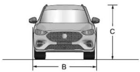
text_image
C B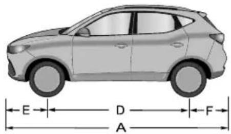
text_image
E D F A| Item,UnitsParameter | |
| OveralllengthA,mm4323 | |
| OverallwidthB,mm1809 | |
| OverallheightC(unladen),mm1628(excludingluggagerack)/1653(includingluggagerack) | |
| WheelbaseD,mm | 2585 |
| FrontOverhangE,mm901 | |
| RearOverhangF,mm837 | |
| Frontwheeltrack,mm | 1521 |
TECHNICALDATA
| Item,UnitsParameter | |
| Rearwheeltrack,mm | 1523 |
| Minimumgroundclearance(laden),mm154 | |
| Minimumturningcirclediameter,m | 11.2 |
| Fueltankcapacity,l | 45 |
Note: Vehiclelengthmeasurement, including all part that meet GB1589 measurement requirement at delivery while not including the license plate.
Note: Rearviewmirrorsandtheformedportionoftyrewalldirectlyabovethetouchdownpointarenotincluded inthetotalwidth.
TECHNICALDATA
Weights
| Item,Units | Parameter | ||
| 1.0T6AT | 1.5L5MT | 1.0T6MT | |
| Personincab,person5 | |||
| Unladenvehicleweight(kerb),kg1255/12641215/1231/12391259 | |||
| Grossvehicleweight,kg173016951722 | |||
| Unladenfrontaxleweight,kg765/769728/737/741760 | |||
| Unladenrearaxleweight,kg | 490/495487/494/498499 | ||
| Ladenrentontaxleweight,kg872 | |||
| Ladenrentaxleweight,kg 827 | 858 | ||
T owingWeights
| Item,Units | |
| Towinglimitunbraked,kg | 500 |
| Towinglimitbraked,kg | 500 |
| Towinghitchload,kg | 50 |
T owingBarDimensions
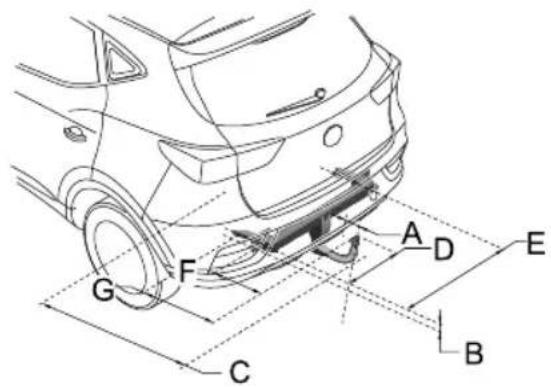
text_image
A D E G F C B| ItemD | DimensionDescription,UnitsParameters | |
| ABumpertocentreoftowball,mm59 | ||
| B | Attachmentpointtocentrethetowball,mm38 | |
| CWheelcentretocentreoftowball,mm893 | ||
| D | Centreoftowballtosidemember,mm469 | |
TECHNICALDATA
| Item | DimensionDescription,UnitsParameters | |
| EDistancebetweenesidemembers,mm | 938 | |
| F | Centreoftowballtocentreoffirstattachmentpoint,mm302 | |
| G | Centreoftowballtocentreofsecondattachmentpoint, mm | 438 |
MajorParametersofEngine
| Vehicle | Parameter |
| 1.0T -AT/MT | |
| Bore×Stroke,mm×mm74×77.4 | |
| Capacity,Litres0.999 | |
| Compressionratio10.5 : 1 | |
| Fueltype,RONUnleaded95RONtoEN228SPEC |
TECHNICALDATA
| Vehicle | Parameter |
| 1.5L-MT | |
| Bore×Stroke,mm×mm75×84.8 | |
| Capacity,Litres1.498 | |
| Compressionratio | 11.5:1 |
| Fueltype,RONUnleaded95RONtoEN228SPEC |
RecommendedFluidsandCapacities
| Name | Grade | Capacity | ||
| 1.5L-5MT | 1.0T-6MT | 1.0T-6AT | ||
| Engineoil(after-sales replacement),L | C50W-204.14 | |||
| Enginecoolant,L | Glycol(OAT)5.45.8 | |||
| Automatictransmission oil,L | AW -I | — | 6.2 | |
| Manualtransmissionoil,L | MTF941.8 | — | — | |
| CastrolBOT503 | — | 1.7 | ||
| Brakefluid,LDOT4 | ||||
| Washerfluid,L | ZY -VIII | 4 | ||
| A-conditioning refrigerant,g | R1234yf | |||
TECHNICALDATA
WheelAlignment(UnladenCondition)
| ItemParameter | ||
| Front | Camberangle | -0^36' ± 45' |
| Casterangle | 4^02' ± 45' | |
| T oe-inangle(T otal) | 0^8' ± 15' | |
| KingpinInclination angle | 12^05' ± 45' | |
| Rear | Camberangle | -1^15' ± 45' |
| T oe-inangle(T otal) | 0^25' ± 20' | |
WheelsandT yres
| Wheelsize7J×17 | |
| T yresize | 215/55R1794V |
T yrePressure(Cold)
| WheelsUnladen | |
| FrontWheels | 230kPa/2.3bar/34psi |
| RearWheels | 230kPa/2.3bar/34psi |
Appendix
304RemovableTowBar
APPENDIX
RemovableT owBar
T owBarOperatingInstructions
Safety:
Operationofthedetachabletowbarshouldonlybe performedbyhand,neverusehandtoolstoooperatethe lockingmechanism.
If the trailer is fitted with a security cable or brakeable it must be attached to the dedicated connection hole in the fixed part of the window bar.
Whenastabilisercouplingisinstalledonthetrailernever usegreaseonthetowball.
Alwaysremovethedetachabletowballwhennotinuseif itobscurestheregistrationplate.
Preparation:
Removetowballcover.
Ensurethetowballiscleanandfreefromdirtanddebris.
Ensurethetowballisinthe'springposition'(seepicture 3.1).
Thetowballisinthespringpositionif:
•Theoperatinghandleispushedincompletelyandno colourindicationisshowninsidetheindicationareaof theoperatinghandle.
- Thesliderispulledfullytowardsthetowball(shownin picture3.1).
- Itisnotpossibletolockthesystemwiththesupplied lockingkeys(seepicture5.2).
ThetowballisNOTinthespringpositionif:
•Theoperatinghandleispoppedoutandshowsared fieldintheindicationareaoftheoperatinghandle(see picture3.1)
- Thesliderispushedouttowardsthetowball(thepart isindicatedbyinpicture3.1).
- Itispossibletolockthesystemwiththesuppliedkeys (seepicture5.2).
T oplacethetowballinthespringposition:
- Unlockthetowball(seepicture6.1)
- Pushtheoperatinghandleinwards,rotateinaclockwise direction(whilstpushinginwards)untilthehandle remainsinposition(seepicture3.2).Ifunsurerepeat operation.
Note: If atowball cannot be tensioned into the spring position it cannot and MUST NOT be used.
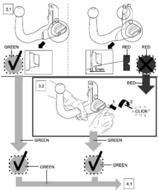
flowchart
graph TD
    A["3.1"] --> B["GREEN ✓"]
    B --> C["1.5mm"]
    C --> D["RED ✓"]
    D --> E["3.2"]
    E --> F["GREEN ✓"]
    F --> G["GREEN ✓"]
    G --> H["4.1"]
    style A fill:#f9f,stroke:#333
    style B fill:#ccf,stroke:#333
    style C fill:#cfc,stroke:#333
    style D fill:#fcc,stroke:#333
    style E fill:#ffc,stroke:#333
    style F fill:#cff,stroke:#333
    style G fill:#ffc,stroke:#333
    style H fill:#cfc,stroke:#333
Attachment:
Beforeattachingthetowballtothecarpleaseremovethe coverfromthehousing(seepicture4.1).
- Inserttowball(thatmustbeinthespringposition)fully intothehousing.
- Holdthetowballinposition,keepingyourhandsaway fromtheoperatinghandle,useaslightforcetopullat thetowballasshowninpicture4.3.
• The unlockingpinwilltriggerthelockingmechanismand thelockingprocesswillautomaticallytakeplace.
•Alwayscheckthetowballiscorrectlyinstalled, this can berecognised by:
•Theoperatinghandlepopsoutandaapproximategap of5millimeterswillbevisiblebetweenthetowballand theoperatinghandle(seepicture5.1). - Agreenfieldwillbevisibleintheindicationareaofthe operatinghandle(seepicture5.1).
- Thetowballcanbelockedusingthesuppliedkeys(see picture5.2). Thiscanonlybedonewhenthehandle haspoppedoutcompletely,afterthisthehandlecanno longerbepushedinandthetowballcannotbereleased (remembertoremovethekeys).
APPENDIX
- Checkthetowballforsecurity-noplayshouldbe evident.
Thetowballisnowreadyforuse.
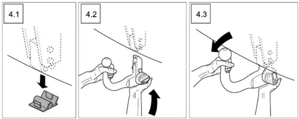
CarePoints
•Alwayscheckthetowballforcorrectmountingevery timepriortouse.
- Neverattempttoattach/detachatowballwhilst trailer/accessoryattached.
•Alwayskeepthetowballcleanandfreefromdebris,do notcleanwithhighpressurewasher.
- Neveruseatowballthatassignsofdamage,excessive wearormodification.
- Neveruseatowballthathasbeeninstalledbyanyother methodthan'handpressure'.
Removal
Always disconnect the trailer/accessory and safetyable prioritotow ball removal.
- Unlockthedetachabletowballbyturningthelocking keyclockwiseusingyourthumbandforefinger(see picture6.1).
-
Holdthetowballwithyourlefthand,pushthe operatinghandlefullyinwardsandturnclockwiseuntil theoperatinghandleremainsinposition(seepicture 6.3).
-
Thetowballcannowberemovedfromthehousingin adownwardmotion(seepicture6.4).WARNING,this itemisheavy,donotallowittodrop.
• Refittheplasticcoverintothehousing(seepicture6.5).
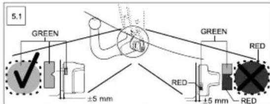
text_image
5.1 GREEN ±5 mm GREEN RED RED ±5 mm RED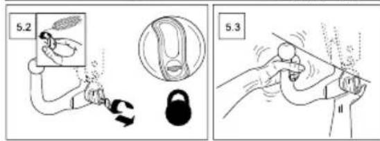
text_image
5.2 5.3APPENDIX