
3 (2016) - Automobile MG - Free user manual and instructions
Find the device manual for free 3 (2016) MG in PDF.


| Product Type | Automobile |
| Model | MG 3 (2016) |
| Overall Length | 4018 mm |
| Overall Width (with mirrors) | 1887 mm |
| Overall Height (unladen) | 1507 mm |
| Wheelbase | 2520 mm |
| Kerb Weight | 1126–1165 kg |
| Gross Vehicle Weight | 1665–1685 kg |
| Engine Capacity | 1.498 L (1498 cc) |
| Maximum Power | 78 kW @ 6000 rpm |
| Maximum Torque | 137 Nm @ 4700 rpm |
| Fuel Type | Petrol, 95 RON |
| Fuel Tank Capacity | 45 L |
| Transmission | 5-speed manual |
| Braking System | ABS, EBD, front disc, rear drum |
| Airbags | Driver, front passenger, side, curtain |
| Seat Belt Pretensioners | Front seats |
| Audio System | CD player, USB, AUX, Bluetooth, DAB* |
| Climate Control | Manual or automatic A/C |
| Power Windows | Front and rear, one-touch down |
| Rear Seats | Split folding |
| Towing Capacity (braked/unbraked) | 200 kg both |
| Tyre Pressure (cold, front/rear) | 2.1 bar (31 psi) |
Frequently Asked Questions - 3 (2016) MG
User questions about 3 (2016) MG
0 question about this device. Answer the ones you know or ask your own.
Ask a new question about this device
Download the instructions for your Automobile in PDF format for free! Find your manual 3 (2016) - MG and take your electronic device back in hand. On this page are published all the documents necessary for the use of your device. 3 (2016) by MG.
USER MANUAL 3 (2016) MG
Printed in July 2015
CONTENTS
Preface....I
Introduction......
The Owner's Handbook....
StatusTimePrinting....I
Symbol Used....I
IrrEmergency....2
VehicleIdentificationInformation....3
Vehicle identification....3
VehicleIdentificationLabel 4
I InstrumentsandControls....5
InstrumentsandControlsOverview......6
InstrumenPack....7
ImperialInstrumentPack * 7
MetricInstrumentPack * 7
Tachometer....8
Speedometer....8
FueGauge....8
MessageCentre....9
CONTENTS
ImperialMessageCentre * 9
MetricMessageCentre * 9
GeaSelectionDisplay....10
VehicleInformationDisplay....10
VehicleInformationInImperialMessageCentre *
VehicleInformationInMetricMessageCentre * 15
Warning Lights and Indicators....20
LightsandSwitches....26
MainLighSwitch....26
FoglightSwitch....27
DirectionIndicators/MairBeamLever 28
Hazard Warning lights....29
Headlight Levelling Manual Adjustment....30
TouringAbroad....31
Wipers and Washers....32
FrontWindscreenWiperControls....32
RainSensor ^* 32
FrontWindscreenWasher....33
RealWindscreenWiperControls....33
CONTENTS
SteeringColumn....35
SteeringColumnAdjustment....35
Horn....36
Mirrors....37
DooMirrors....37
InteriorRear-viewMirror....39
SunVisor....41
Windows....42
PowerOperatedWindowControls....42
WindowOperation....42
Interior Lights....44
Interior Lamp....44
CentreConsolePowerSocket....45
StorageEquipment....46
Instructions....46
Glovebox....46
StorageBox....47
FrontPassengerLowerStorageBox * 47
CONTENTS
CupHolder....48
2ClimateControl....49
ClimateControl....50
Ventilation....50
HeaterControls ^* 52
AirConditioningControls * 55
3AudioSystem....59
CDPlayer * (LowLine)....60
Usinstructions....60
CDPlayerControPanel....61
BasicOperation....62
RadioFunction....65
CDPlaying....67
USB....68
AUX....69
Antenna....69
CDPlayer * (HighLine)....70
UsInstructions....70
CONTENTS
CDPlayerControPanel....71
SteeringWheeControButton....72
BasicOperation....73
MenuOperation....76
FM/MW....78
DAB ^* 80
CDPlaying....81
USB....82
iPod/iPhone ^® 83
AUX....84
Bluetooth....84
Antenna....86
4Seats&Restraints....87
Seats......88
Correct Seating Position....88
HeadRestraints....89
ManuaFronSeat....90
FoldingtheReaSeats....91
SeaBelts....92
CONTENTS
SeaBelts....92
SeaBelPre-tensioners....94
AirbagSupplementaryRestraintSystem(SRS)......95
Airbags....95
ChildRestraints....103
ChildRestraintnstructions....103
Starting&Driving......III
Key......112
Introduction......112
RemoteKeyBatteryRemovingandRefitting....113
Child-ProofLocks....115
AlarmSystem....116
Locking and Unlocking....116
Starting and Driving....121
Dockingstation....121
StartingheEngine....122
Stopping the Engine....123
CONTENTS
EconomicalandEnvironmentalDriving....125
Running-in....125
EnvironmentProtection....125
Drivingstyle....125
How to save and extend the life of the vehicle....126
Maintenance....127
CatalyticConverter....128
Fuel....128
Starting....128
Driving....129
FueSystem....130
FueRequirements....130
FueFiller....131
FueFilling....131
FuelCut-offSwitch....131
Manual transmission....133
Gealever....133
BrakeSystem....134
FooBrake....134
CONTENTS
Anti-loc|Brakes(ABS)....136
ParkingBrake....137
StabilityControlSystem(SCS)andT ractionControl(TC)....139
StabilityControSystem(SCS)....139
TractionControl(TC)....139
SwitchingOrandOff....140
SCS/TCWarninglight....140
Stop/StartIntelligentFuelSavingSystem....141
AutomatiShutdownEngine....142
AutomaticEnginStart....142
Battery....143
Stop/StartIntelligenFueSavingSystemFailure....144
SeriousBatteryCapacityLossStartelnoperative....144
CruiseControlSystem * 145
CruiseControSystem....145
ParkingAid-PDC(ParkingDistanceControl) * 147
ParkingAid(Ultrasonic Parking Ranging Warning Devices)....147
T yrePressureMonitoringSystem(TPMS)....149
LoadCarrying....151
CONTENTS
LoadSpace....151
InternalLoading....151
6EmergencyInformation....153
HazardWarningDevices....154
Hazard Warning lights....154
Warning Triangle....154
EmergencyStarting....155
Using Booster Cables....155
Startinghe/vehicle....155
VehicleRecovery....157
TowingEye....157
TowingoRecovery....158
TyreRepair&WheeReplacement....160
T oollidentification ^* 160
TyreRepair ^* 161
AccessingtheSpareWheelandT ools * 164
Changing Wheel....165
FuseReplacement....168
CONTENTS
Fuse....168
FusBox....169
Passenger Compartmen Fus Box....169
Engine Compartmen Fus Box....172
BullReplacement....174
BullSpecification....174
BullReplacement....175
Maintenance....177
Maintenance....178
RoutinServicing....178
Bonnet....182
OpeninghBonnet....182
ClosinghBonnet....182
Warning/WhertheBonnetOpen....182
EngineCompartment....183
Engine Compartment(LHD)....183
EngineCompartment(RHD)....184
Engine....185
CONTENTS
EngineOil....185
CoolingSystem....187
CoolanCheclandTopUp....187
CoolanSpecification....187
Antifreeze....188
Brakes....189
BrakeFluid....189
Brake Fluid Specification....190
PowerSteering....191
PowerSteeringFluidCheclandTopUp....191
PowerSteeringFluidSpecification....192
Battery....193
Battery Safety....193
Battery Disconnection and Replacement....193
BatteryCharging....194
BatteryMaintenance....195
Washers....197
WindscreenWasherCheelandTopUp....197
WasheNozzles....198
CONTENTS
Washing Fluid Specification....198
Wiper....199
WipeBlade....199
ReplacingFrontWipeBlades....200
Replacing Real Wiper Blades....200
Tyres....202
Overview....202
NewT yres....202
DirectionalT yres....202
TyrdLife....202
TyrPressures....202
Drivingstyle....203
WheeBalance....203
WheelAlignment....203
CaringoY ourT yres....203
TyrPressures....203
Valves....204
PuncturedT yres....204
TyréV ealindicators....204
CONTENTS
ReplacementT yres....205
WheeFitmenRotation....205
SnowChains....205
CleaningandVehicleCare....207
Washing YourCar....207
VehicleGraphicCare....209
Cleaninghenterior....210
8TechnicaData....213
TechnicaDataDimensions....214
Weights....215
TowingWeights....215
MajorParametersEngine....216
RecommendedFluidsandCapacities....217
WheelAlignment(UnladenCondition)......218
WheelandTyres....218
TyrePressure(Cold)......218
Introduction
TheOwner'sHandbook
This handbook describes all of the vehicles and standard equipments specification within the model range. Some of the information therefore, may not apply to your particular car.
Alwaysrememberthatifyouhaveanyqueriesconcerning theoperationorspecificationofyourcar,yourMG AuthorisedRepairerwillbegladtoadviseyou.
StatusatTimeofPrinting
MGoperatesapolicyofconstantproductimprovement andthereforereservestherighttochangespecifications withoutnoticeatanytime.Whilsteveryeffortis madetoensurecompleteaccuracyoftheinformation inthispublication,noliabilitiesforinaccuraciesorthe consequencesthereof,includinglossordamageto property,orinjurytopersons,canbeacceptedbythe manufacturerorMGAuthorisedRepairerwhosupplied thepublication,exceptinrespectofpersonalinjurycaused bythenegligenceofthemanufacturerorMGAuthorised Repairer.
SymbolsUsed
The following symbols used within the handbook can your attention to specific types of information.
Warning

This warningsymbolidentifies procedures that must be followed precisely, information that must be considered with great care, in order to reduce the risk of personal injury or serious damage to the car.
Important
IMPORTANT
Thestatementsstatedheremustbefollowedstrictly, otherwiseyourcarcouldbedamaged.
Note
Note: This describes helpful information.
PREFACE

Thissymbolindicatesthatpartsdescribedmustbe disposedofbyauthorisedpersonsorbodiestoprotect theenvironment.
Asterisk
Anasterisk(*)appearingwithinthetext,identifiesfeatures oritemsofequipmentthatareeitheroptional,orareonly fittedtosomevehiclesinthemodelrange.
IllustrationInformation

Identifiescomponentsbeingexplained.

Identifies movement of components being explained.
AllillustrationsinthishandbookarebasedonaRHD vehicleexceptwhereLHDmodelisstated.
InanEmergency
IMPORTANT
Rememberthebreakdownsafetycode
Ifabreakdownoccurswhiletravelling:
- Whereverpossible,consistentwithroadsafetyand trafficconditions,thecarshouldbemovedoffthe mainthoroughfare,preferablyintoalay-by.lfa breakdownoccursonamotorway,pullwelloverto theinsideofthehardshoulder.
- Switchonhazardlights.
•Ifavailable,positionawarningtriangleoraflashing amberlight50to150metres(150to500ft)behind yourvehicletowarnapproachingtraffic.Noteitisa legalrequirementofsomecountriesthatawarning triangleiscarriedinthevehicle,ifindoubtconsult thelocalhighwaysagencyforfurtherinformation.
- Considerevacuatingpassengersthroughnearside doorsontothevergetoreduceriskofinjuryinthe eventofcollision.
VehicleIdentificationInformation
VehicleIdentification
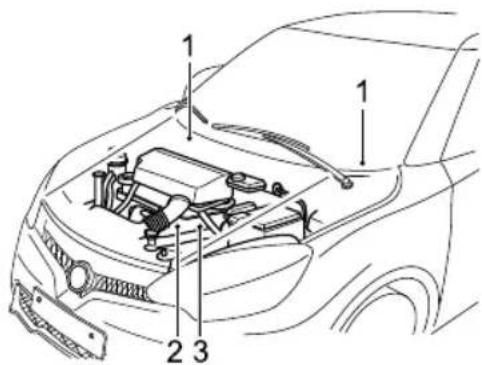
IVehicleIdentificationNumber(VIN)
2EngineNumber
3TransmissionNumber
AlwaysquotetheVehicleIdentificationNumber(VIN) when communicating with your MGAuthorised Repairer.
VINLocation
- Stampedonaplatevisiblethroughthebottomlefthand cornerofthewindscreen.
•Ontheidentificationplate. - Ontherightsidepanelupperframeintheengine compartment.
EngineNumberLocation
Stampedontherearofthecylinderblock.(Viewfromthe frontoftheengine)
T ransmissionNumberLocation
Onalabelattachedtotheupperfaceofthetransmission housing.
PREFACE
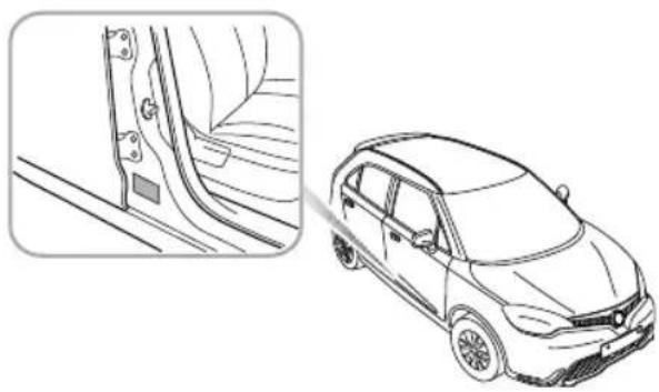
VehicleIdentificationLabel
The vehicle identification label contains the following information.
•TypeApprovalNumber
•VehicleIdentificationNumber(VIN)
•GrossVehicleWeight
•GrossT rainWeight
•MaxFrontAxleWeight
•MaxRearAxleWeight
- PaintCode
- TrimCode
LocationofV ehicleIdentificationLabel
natural_image
Line drawing of a car exterior and side view showing the door panel and dashboard (no text or symbols)The VehicleIdentificationLabelislocatedonthebottom oftherightsidepillarB.
InstrumentsandControls
6InstrumentsandControlsOverview
7 InstrumentPack
9MessageCentre
20WarningLightsandIndicators
26LightsandSwitches
32 WipersandWashers
35SteeringColumn
36Horn
37 Mirrors
41 SunVisor
42 Windows
44InteriorLights
45 CentreConsolePowerSocket
46 StorageEquipment
48 CupHolder
INSTRUMENTSANDCONTROLS
InstrumentsandControlsOverview
InstrumentsandControls ( ( RHD ) )
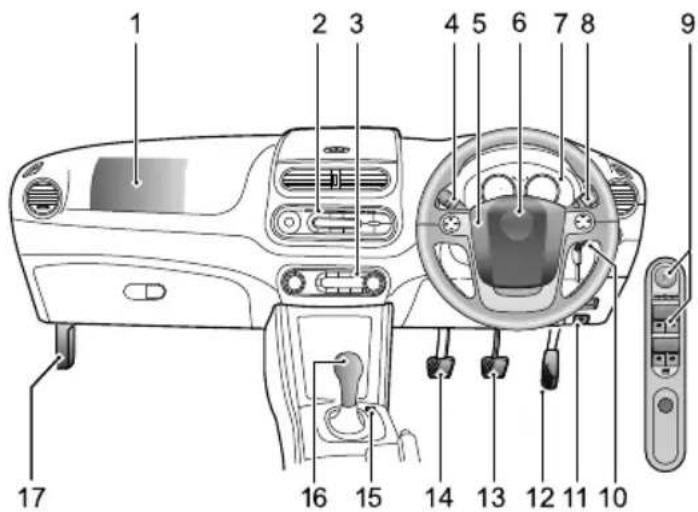
IFrontPassengerAirbag
2EntertainmentSystem
3HeatingandAirConditioningControlSwitch
4MainLightsSwitch/DirectionIndicators/Main BeamSwitch/RearFogLights
5Horn
6DriverAirbag
7InstrumentPack
8Wiper/WasherSwitch
9ElectricExteriorMirrorandWindowControls
10IgnitionSwitch
IIFuelFillerFlapReleaseHandle
12AcceleratorPedal
13BrakePedal
14ClutchPedal
15SCSOFFSwitch
16GearShiftLever
17BonnetRelease
INSTRUMENTSANDCONTROLS
InstrumentPack
ImperialInstrumentPack *
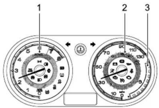
MetricInstrumentPack *
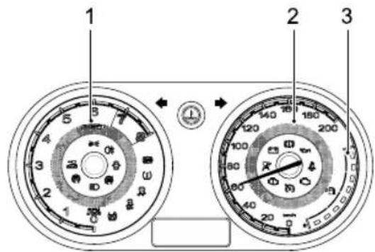
Note: Thespeedometer in the Imperial Instrument Pack is measured in both MP Hand km/h. Thespeedometer in the Metric Instrument Pack is measured in km/h.
INSTRUMENTSANDCONTROLS
T achometer
Indicate the enginespeed (figure 1) in revolutions per minute ( × 1000).
IMPORTANT
T oprotecttheenginefromdamage,neverallowthe pointertoremainintheredsectorofthegaugefor prolongedperiods.
Speedometer
Indicatetheroadspeed(figure2), Thespeedometer of the Imperial Instrument Pack is measured in MP Hand km/h. Thespeedometer of the Metric Instrument Pack is measured in km/h.
FuelGauge
The quantity offuelin the tank is indicated by the number of segments illuminated. There are eight segments total (figure 3). Whenthe fuel level is full, alleight segments are illuminated in white. Whenthe fuel level is slow, the lowest segment changest yellow from white, and a warning sound will be heard. If the fuel level continues to fall to acritical state, the lowest segment will flash and a audible warning will sound again.
IMPORTANT
Whenthefuellevelislow,refuelattheearliest opportunity.Neverallowthecartorunoutoffuel. Theresultantmisfirecoulddamagethecatalytic converter.
Thearrownexttothelowfuelwarninglightindicates that thefuelfillerislocatedontherighthandsideofthevehicle.
INSTRUMENTSANDCONTROLS
MessageCentre
ImperialMessageCentre *
MetricMessageCentre *
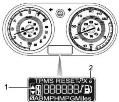
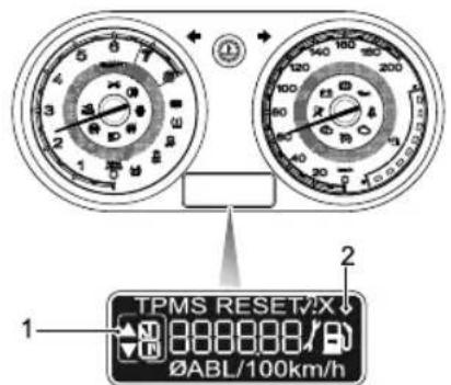
The message cent relocated the bottom of the instrument pack and provides following information:
GeaSelectionDisplay
VehicleInformationDisplay
Note: The imperia Message Centre measure imperial unit. The Metric Message Centre measure metric units.
INSTRUMENTSANDCONTROLS
GearSelectionDisplay
Thissegmentofthemessagecentreindicatesthecurrent gearleverposition.
Whenthecarisstationaryandneutralpositionisselected, thedisplaywillindicateN.Whenreversegearisselected, thedisplaywillindicateR.
Whenthecarisinmotion, the display are a will indicate the current gear selected (e.g. N, R, I, 2, 3, 4, 5). An indicator will be displayed in this area when age change is advised. The upordownarrows flashestore mind the driver to upshift or downshift.
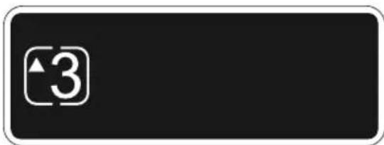
Note: If the clutch is pressed, the geard display is inhibited.
VehicleInformationDisplay
natural_image
Mechanical component diagram showing a tool interacting with a curved mechanical part (no text or symbols visible)The vehicle information displays screen provides the following information:
•Odometer
- TripDistanceA
- TripDistanceB
•AmbientT emperatureDisplay
•FuelRangetoEmpty
• InstantaneousFuelConsumption
INSTRUMENTSANDCONTROLS
•AverageFuelConsumption
•AverageSpeed
- NextService
- TPMSReset
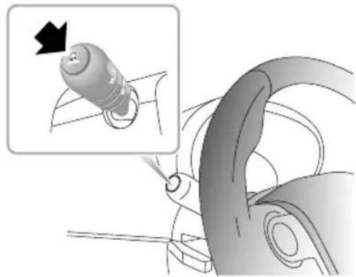
Repeatedlypressthebuttonontheendofthemainlight switch(indicatedbyarrowindiagram)forlessthan2 seconds,andthentheaboveinformationwillbedisplayed incycles.
Bypressingandholdingthebuttonontheendofthemain lampswitchforlongerthan2seconds,theselecteddisplay canbereset(includingtripdistanceA,tripdistanceB, averagefuelconsumptionoraveragespeed).
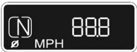
VehicleInformationInImperialMessage Centre\*
Odometer
Showsthetotaldistancethatthecarhastravelled.
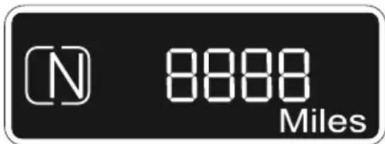
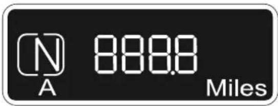
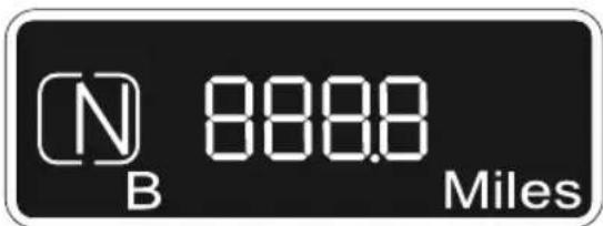
T ripDistanceAandT ripDistanceB
Thisdisplayshowsthedistancetravelledsincethetrip recordwaslastreset.
TripdistanceAandtripdistanceBareindependent distancerecords, Displayrangeof0-9999miles, If themileageislessthan 1000miles, itchangesin0. I mileincrements, morethan 1000miles, itchangesin I mileincrementstoamaximumof9999mileswhenitis
INSTRUMENTSANDCONTROLS
automaticallyreset,tripAandtripBcanberesetatany time,soastorecordvehiclemileage.
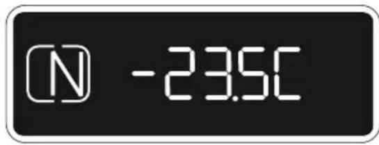
AmbientT emperatureDisplay
Displayindicate the ambient air temperature of the air outside the vehicle.
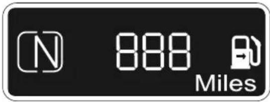
FuelRangetoEmpty
Display the approximateremaining distance that can be travelled before the vehicle needs refuelling. The distance will changewhenthe vehicle is refuelled.
Fuelrangetoemptyiscalculatedaccordingtofuel remainingandtheaveragefuelconsumptionisbased onacombinationofcurrentdrivingstyleandthefuel consumptionrecordedbythecomputerduringthe previousfewminutes.
INSTRUMENTSANDCONTROLS
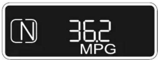
InstantaneousFuelConsumption
This function is automatic and indicates the instantaneous fuel consumption. When the vehicle stops moving or stops using fuel, then the instantaneous fuel consumption display shows “—MPG”.
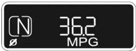
AverageFuelConsumption
This function is automatic and indicates the average fuel consumption sincethelasttimethetripcomputer was reset (average consumption is calculated by dividing the distancetravelled by the amount off fuel used). The consumption value can be reset at any time to begin calculating new consumption values for a particular journey or driving conditions.
Theaveragefuelconsumptionshallbecalculatedafterthe enginestartswhenthevehiclespeedexceeds3MPH.
Note: Average consumption is related to driving habits, road condition, load, tyre pressure, the quality of oil, etc.
INSTRUMENTSANDCONTROLS
AverageSpeed
Thisfunctionisautomaticandindicatestheaveragespeed sincethelasttimeitwasreset.Theaveragespeeddisplay canberesetatanytimetobegincalculatinganewaverage speedvalueforaparticularjourneyordrivingcondition.
NextService
Showstheserviceintervalannouncementsymbol,the estimateddistanceofthenextserviceremainingbeforeit shouldbecarriedout.
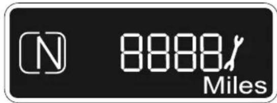
Note: The Service Interval Announcement information can only be reset by an MGA authorised Repairer.
TPMSReset
Enter 'TPMSRESET?' displayinterface.Bypressingand holdingthebuttonforlongerthan2seconds.lfthetext 'TPMSRESET' is displayed. It indicates TPMSreset successful. If the text 'TPMSRESETX' is displayed. It indicates TPMSresetfail.consult your MGA authorised Repairer.
INSTRUMENTSANDCONTROLS
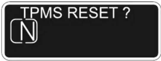
Note: The TPMSresetmenuwillonlybemade availablewhenthecarisstationary, withthehand brakeappliedandignitiononpositionII.
VehicleInformationInMetricMessage Centre*
Odometer
Showsthetotaldistancethatthecarhastravelled.
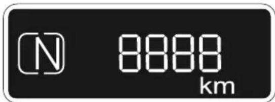
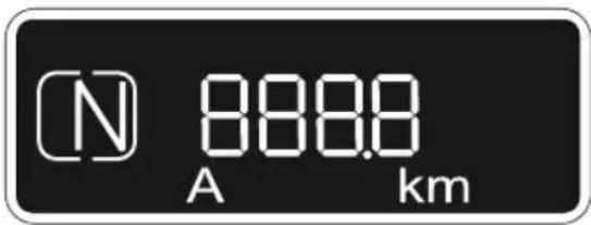
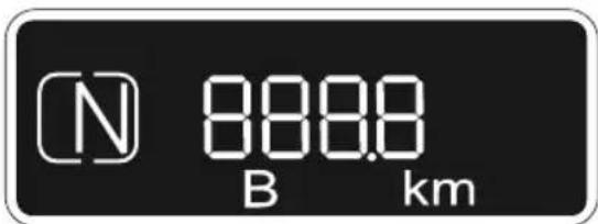
T ripDistanceAandTripDistanceB
Thdisplayhowshdistanceravelledincttrip recordwaslastresert.
TripdistanceAandtripdistanceBareindependent distancerecordDisplayang9991, thedistanceislessthan1000kritchangesin0.1 kimcrementsmorthan000kri changed kimcrementsmaximumof999Rn wheels
INSTRUMENTSANDCONTROLS
automaticallyreset,tripAandtripBcanberesetatany time,soastorecordvehiclemileage.
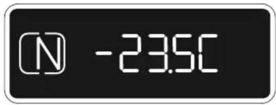
AmbientT emperatureDisplay
Displayindicate the ambient temperature of the air outside the vehicle.
FuelRangetoEmpty
Display the approximateremaining distance that can be travelled before the vehicle needs refuelling. The distance will changewhenthe vehicle is refuelled.
Fuelrangetoemptyiscalculatedaccordingtofuel remainingandtheaveragefuelconsumptionisbased onacombinationofcurrentdrivingstyleandthefuel consumptionrecordedbythecomputerduringthe previousfewminutes.
INSTRUMENTSANDCONTROLS

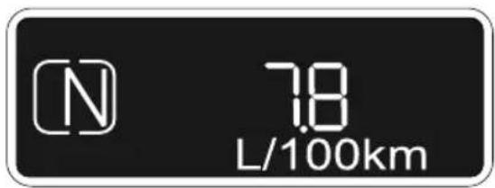
InstantaneousFuelConsumption
This function is automatic and indicates the instantaneous fuel consumption. When the vehicle stops moving or stops using fuel, then the instantaneous fuel consumption display shows “—L/100km”.
AverageFuelConsumption
This function is automatic and indicates the average fuel consumption sincethelasttimethetripcomputer was reset (average consumption is calculated by dividing the distancetravelled by the amount off fuel used). The consumption value can be reset at any time to begin calculating new consumption values for a particular journey or driving conditions.
Theaveragefuelconsumptionshallbecalculatedafterthe enginestartswhenthevehiclespeedexceeds5km/h.
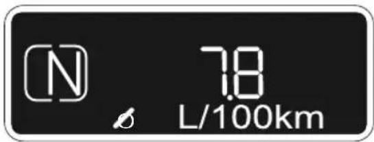
Note: Average consumption is related to driving habits, road condition, load, tyre pressure, the quality of oil, etc.
INSTRUMENTSANDCONTROLS
AverageSpeed
Thisfunctionisautomaticandindicatestheveragespeed sincethelasttimeitwasreset.Theaveragespeeddisplay canberesetatanytimetobegincalculatinganewaverage speedvalueforaparticularjourneyordrivingcondition.
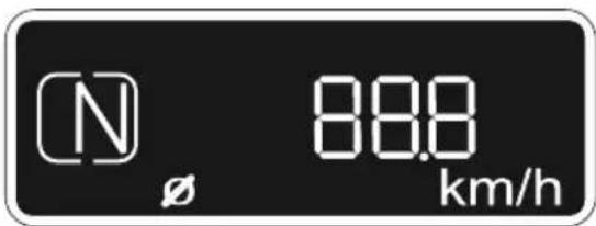
NextService
Showstheserviceintervalannouncementsymbol,the estimateddistanceofthenextserviceremainingbeforeit shouldbecarriedout.

Note: The Service Interval Announcement information can only be reset by an MGA authorised Repairer.
TPMSReset
Enter 'TPMSRESET?' displayinterface.Bypressingand holdingthebuttonforlongerthan2seconds.lfthetext 'TPMSRESET' isdisplayed.It indicates TPMSreset successful.lfthetext 'TPMSRESETX' isdisplayed.It indicates TPMSresetfail.consultyourMGAuthorised Repairer.
INSTRUMENTSANDCONTROLS
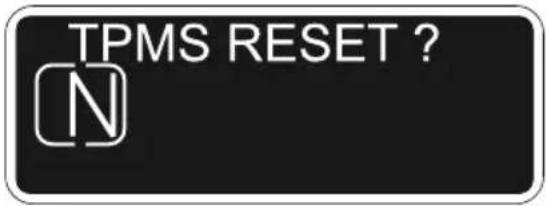
Note: The TPMSresetmenuwillonlybemade availablewhenthecarisstationary, withthehand brakeappliedandignitiononpositionII.
INSTRUMENTSANDCONTROLS
WarningLightsandIndicators
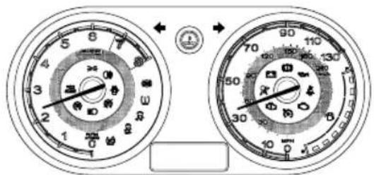
MainBeam-Blue

Illuminateswhentheheadlightsareswitchedto
mainbeam.
SideLamps-Green

Illuminateswhenthesideorheadlightsare
switchedon.
DirectionIndicators-Green

Theleftandrightdirectionindicatorsare
representedbydirectionalarrowslocatedatthetopofthe instrumentdisplay. Thewarninglightsflashsynchronised withtheexteriorleftorrightdirectionindicatorlights whenevertheyareoperating.
If the hazard warning lights are operated, both warning lightswillflashtogether.
Ifeitherwarninglightflashesveryrapidly,thismeansthat oneofthefrontorreardirectionindicatorlightsisnot operating.
Note: Failureofasiderepeaterlightwillhavenoeffect onthewarninglightflashfrequency.
INSTRUMENTSANDCONTROLS
RearFogLight-Y ellow

Illuminateswhentherearfoglightsareswitched
on.
Airbag-Red

Thewarninglightilluminatesasalampcheck
whentheignitionisswitchedon.Ifthelightilluminates atanyothertimeorfailstoextinguishafterstartup,an airbagrestraintsystemfaulthasbeendetected,thenan audiblewarningwillbegivenwhentheengineisstarted. Seekqualifiedassistanceurgently.
SeatBeltWarning-Red

Ifaseatbeltforanoccupiedfrontseatremains unfastened, the warning light willilluminate. Anaudible warning is heard to remind the riverto ensure that both seat belts are securely fastened. If these belt for an occupied seat remains unfastened on the vehicles speed
hasexceeded 15MPH(25km/h), the warninglamp will flash accompanied by a audible warning. The warning will continue until either these at belt is fastened correctly or 90 second shas expired.
LowOilPressure-Red

Thewarninglightilluminateswhentheignition isswitchedonandextinguisheswhentheengineisrunning. Ifthelightremainsonorilluminatescontinuouslywhen driving,seriousenginedamagecouldoccur;stopthe vehicleassoonassafetypermitsandSWITCHOFFTHE ENGINEIMMEDIATELY.Seekqualifiedassistancebefore driving.
BatteryCharging-Red

Thewarninglightilluminateswhentheignition isswitchedonandextinguishesassoonastheengineis running. Ifthelightremainsonorilluminateswhendriving, afaultwiththebatterychargingsystemisindicated. Seek qualifiedassistanceurgently.
INSTRUMENTSANDCONTROLS
ABS-Y ellow

Thewarninglightilluminatesasalampcheck whentheignitionisswitchedon,Ifthelightisilluminates, afaulthasoccurredwiththeABSsystemandyoushould seekqualifiedassistanceattheearliestopportunity.
IfanABSfaultoccurswhiledriving,ABSoperationwillbe suspended,butnormalbrakingwillstillbeavailable.Seek qualifiedassistanceattheearliestopportunity.
ParkingBrake/BrakeSystemLight-Red

Thewarninglightilluminatesasalampcheck whentheignitionisswitchedon, Subsequentillumination may indicateafaultwiththebrakingsystemsuchasparking brakeonorbrakefluidlevelisloworelectronicbrakeforce distributionfailure.
Thelightilluminateswhentheparkingbrakeisapplied and extinguisheswhenitisfullyreleased.Iftheparkingbrakeis inadvertentlyleftapplied,thelightwillflashandanaudible warningwillsoundwhenthevehiclespeedexceeds3MPH
(5km/h). If the warning light remains illuminated after the parking brake has been released, a fault with the braking system is indicated. Check the brake fluid level. If the light continues to illuminate, stop the car as soon as safety permits and seek qualified assistance urgently.
Whentheignitionswitchisoffandthedriver'sdooris open,iftheparkingbrakehasnotbeenapplied,theparking brakealarmwillbeactivated,andthewarninglightwillflash accompaniedbyanaudiblewarning.
EngineEmissionFault-Y ellow
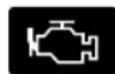
This warning light which is used to indicate anemissionsrelatedfaultisdetectedbytheengine managementsystem. Thewarninglightilluminatesasa lampcheckwhentheignitionisswitchedon,Ifanengine operationproblemoccurswhilethevehicleisbeingdriven, theindicatorwillilluminate.Seekqualifiedassistance.
INSTRUMENTSANDCONTROLS
EngineCheck-Y ellow
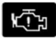
This warning light is used to indicate an engineoperationfaultwhichisdetectedbytheengine managementsystem. Thewarninglightilluminatesas alampcheckwhentheignitionisswitchedon, Ifa non-emissionsrelatedfaultoccurswhilethevehicleis beingdriven, theindicatorwillilluminate. Seekqualified assistance.
EngineCoolantT emperatureWarningLight-Red/Blue

Thewarninglightisusedtoindicatethe temperatureofenginecoolant. Thewarninglight illuminatesasasystemcheckwhentheignitionisswitched on. If the warning light illuminates blue, it indicates that the coolant temperature is slow, and if the warning light illuminates red, it indicates that the coolant temperature is high, Whentetemperaturecontinuestorise, the
warninglightwilflashaccompanied byaudiblewarning. If the signals missing the warning light flashed blue.
If the engine is too hot, severed damage could result; stop the vehicle as soon as safety permits and seek qualified assistance at the earliest opportunity.
StabilityControSystem(SCS)Y ellow

The warning light indicates that the SCSystem isworkingorfault thewarninglightilluminatesasa lampcheckwhentheignitionisswitchedon,IftheSCS systemisworkingthewarninglightofftheSCSsystem hasafault,thiswarninglightwillstayostopthecar assoonassafetypermitsandcontactanMGAuthorised Repairer.WhentheSCSsystemhasaninterventionevent. thewarninglightwillflash.
StabilityControSystem(SCS)OffYellow
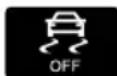
The warning light indicates that the SCSystem
isswitchedonoroff. Thewarninglightilluminatesasa
INSTRUMENTSANDCONTROLS
lampcheckwhentheignitionisswitchedon,Ifthefunction oftheSCSsystemisoff.thewarninglightwillilluminateall thetime.
T ractionControl(TC)WarningOff-Y ellow

Thewarninglightindicatesthatthetraction controlisswitchedonoroff. Thewarninglightilluminates asalampcheckwhentheignitionisswitchedon, If the TCfunctionismanuallyswitchedoff, the warninglightwill illuminateallthetime.
T yrePressureMonitoringSystem(TPMS)-
Y ellow

Thewarninglightilluminatesasalampand systemcheckwhentheignitionisswitchedon.Ifalow tyrepressureisdetectedthewarninglightwillilluminate. Ifthelightflashesyellow,ltindicatesthesystemhasafault. Adjustyourtyrepressuresorseekqualifiedassistance.
EngineImmobilizer/KeyBatteryLow-Red
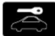
Thewarninglightdoesnotilluminatewhen theignitionisswitchedon.Iftheengineimmobilizer verificationfails,theenginecannotbestarted,andthe warninglightwillbeilluminated.Iftheremotekeyvoltage istoolow,thewarninglightwillflashaccompaniedbyan audiblewarning.
PanelOpeningWarning-Red
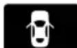
Thewarninglightindicatesthatthevehicle doors, bonnetortailgatearenotclosed. The warninglight does not illuminate when the ignition is switched on. If there is a door, bonnetortailgatenotclosed, the warning light willilluminate. If the panel remains open on the vehicles speed has exceeded 3 MPH (5 km/h), the warning light will flash accompanied by an audible warning. The warning will continue until all panels are closed correctly or 30 second has expired.
INSTRUMENTSANDCONTROLS
CruiseControl-Y ellow/Green\*

Thewarninglightdoesnotilluminatewhenthe ignitionisswitchedon.Itwillilluminateinyellowwhen cruisecontrolisactiveandgreenwhenthemasterswitch ispressedbutnocruisespeedisactive.lfafaultisdetected, thewarninglightwillflashyellow.
When cruise control isset, the targets speed is shown in LCD, the targets speed remains displayed until the actual speed is achieved, at which point the LCD revert to its previous display.
IntelligentStop-StartEnergy-SavingSystem
Status-Green

Iftheintelligentstop-startenergy-savingsystem
isactivated, this lightilluminatestoindicatetothedriver that the engine is being controlled by the intelligent stop-start energy-savingsystem. When the Stop-Start function is inhibited, the lightwillextinguishafter flashing 3 times.
IntelligentStop-StartEnergy-SavingSystem
MalfunctionWarning-Y ellow

Ifthelightilluminatesduringdriving,thenthe
Stop-Startsystemhasdetectedafault.ContactanMG AuthorisedRepairerforadvice.
INSTRUMENTSANDCONTROLS
LightsandSwitches
MainLightSwitch

ISide/Tail/InstrumentPackLights
2Headlights
3AUTOLights
SideLights,T ailLights,InstrumentPackLight
Turnthemainlightswitchtoposition I to switch on the side, tailandinstrumentpacklights, the sidelight indicator will illuminate.
Ifthelightsarestillswitchedonwhenthdriver'sdooris openedandthekeyisremoved,anaudiblewarningwillbe given.
Headlights
Turnthelightingswitchtoposition2toswitchonthe headlights.
Theheadlightswillonlyilluminatewhentheignitionis switchedon.
AUTOLights \*
Withtheignitionisswitchedon,turnthelightingswitchto AUTOposition3.TheAUTOlightingsystemconstantly monitorstheambientlightlevelsandautomatically switchestheappropriatelightsonandoffasrequired.
INSTRUMENTSANDCONTROLS
FogLightsSwitch

Foglightsshouldbeusedonlywhenvisibility isverypoor;otherroaduserscouldbe dazzledinclearconditions.
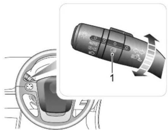
I RearFogLights
RearFogLights
Whentheignitionswitchisatposition2andtheheadlights areswitchedon,switchtherearfoglights(figure1)tothe ONposition,andtherearfoglightswillilluminate.The warninglightintheinstrumentpackwillilluminatewhen thefoglightsareon.
INSTRUMENTSANDCONTROLS
DirectionIndicators/MainBeamLever

T akecarenottodazzleoncomingvehicles whendrivingusingmainbeamheadlights.
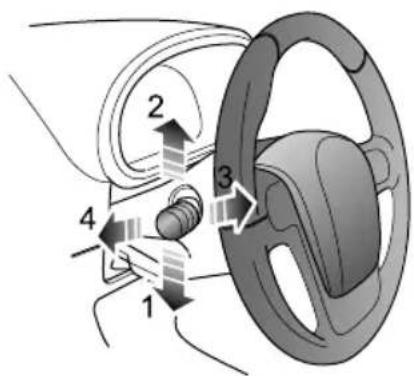
I Pressdownwardtoindicatealeftturn
2Pressupwardtoindicatearightturn
3Mainbeamflash
4Pushawayformainbeam
DirectionIndicators
MovetheleverdowntoindicateaLEFTturn(figure1),or uptoindicateaRIGHTturn(figure2).Theindicatorswill cancelautomaticallyonceaturnhasbeencompleted.
ThecorrespondingGREENwarninglightintheinstrument packwillflashintimewiththedirectionindicators.T o indicatealanechange,presstheleverbrieflyandrelease, theindicatorswillflashthreetimesandthencancel.
HeadlightMainandDippedBeam
Whentheignitionswitchisonandthemainbeamswitch isinposition2, pushtheleverfullytowardstheinstrument pack(figure4)toswitchonmainbeam(theBLUEwarning lightintheinstrumentpackilluminates). Fullypushthe leverswitchtowardstheinstrumentpack(figure4)toturn offmainbeamandreturntodippedbeamheadlights.
HeadlightsFlash
T obrieflyflashthemainbeamonandoff, pullthelever towardsthesteeringwheel(figure3) and then release.
INSTRUMENTSANDCONTROLS
FollowMeHome(HeadlightsDelayedOFF)
Afterthevehicleisstopped,turnofftheignitionand removekey.Momentarilypushorpulltheindicatorlever switchandreleasewithin l minutetoactivatethedipped beamheadlamps. Thelampswillremainilluminatedfor approximately30seconds.T oswitchoffthelampsduring thistimeperiod,pushorpulltheindictorleverswitchfor asecondtime.
DaytimeRunningLights
Thedaytimerunninglightsturnonautmaticallywhen theignitionswitchisinposition2.Whenthesideor headlightsareswitchedon,thedaytimerunninglightsare extinguished.
HazardWarningLights
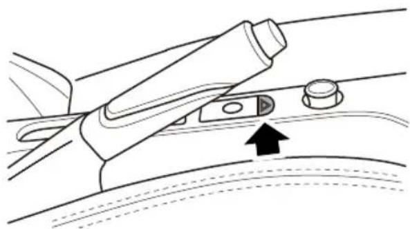
Hazardwarningswitchlocationisdependentupontrim level.
natural_image
Technical line drawing of a mechanical component with a black arrow indicating a specific part (no text or symbols present)Vehiclesfittedwithelectronicairconditioningfeaturethe switchinthecentreconsoleadjacenttothepassenger airbagdisableswitch.
INSTRUMENTSANDCONTROLS
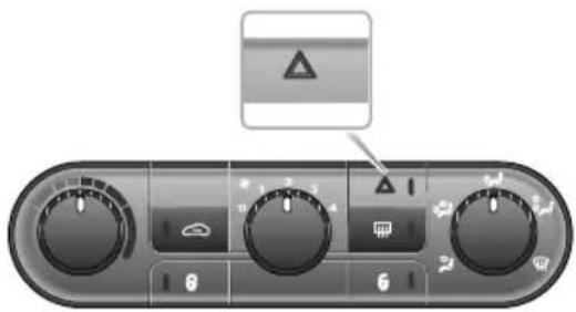
Vehiclesfittedwithastandardheaterfeaturetheswitchin theheatercontrolpanel(seepicture).
Pressthebuttontooperatethehazardwarninglights, all ofthedirectionindicatorswillflashtogether.Pressagain toswitchoff.
HeadlightLevelling-ManualAdjustment
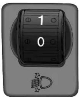
The angle of the dipped beam is affected by the distribution of passenger and luggage weight within the car.
To ensure correct headlampaim, and not dazzleon-coming traffic, the headlamplevellingswitch positions should be adjusted according to the vehicle loading condition in accordance with the following table:
INSTRUMENTSANDCONTROLS
| PositionLoad | |
| 0Driver,ordriver&frontpassenger | |
| 1 | Alltheseatsoccupiedwithnoload |
| 2 | Alltheseatsoccupiedplusanevenly distributedloadintheboot,ordriver withfullload |
| 3 | Driveronly,plusanevenlydistributed loadintheboot |
T ouringAbroad
If your journey takes out countries where cars are driven on the opposites side of the road to your country it will be necessary to fit the clamp beam deflectors.
ContactyourMGdealerforfurtherdetails.
INSTRUMENTSANDCONTROLS
WipersandWashers
FrontWindscreenWiperControls
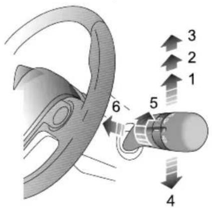
Thewipersandwasherswilloperatewiththeignitionin position I orposition2.
Pushtheleveruptoselectdifferentwiperspeeds:
- Intermittentwipe/automaticwipe(I)
•Normalspeedwipe(2)
•Fastspeedwipe(3)
IMPORTANT
- Avoidoperatingthewipersonadryscreen.
• Infreezingorveryhotconditions, ensure that the blades are not frozen or stuck to the glass before being operated.
• Inwinter, removesnoworicefromaroundthearms andblades, includingthewipedareaofthescreen.
SingleWipe
Pullthelever(4)downandrelease(iftheleverisheld down,thewiperswilloperateathighspeeduntilthelever isreleased).
VariableDelay-intermittentwipe
T oselectintermittentwipepushtheleveruptoposition(1), Rotatetheswitch(5)tovarytheintermittenttimeofwiper operation.
RainSensor \*
Somemodelsareequippedwitharainsensorfittedto theinsideofthewindscreenbehindtherearviewmirror.
INSTRUMENTSANDCONTROLS
Thesensorisabletodetectvaryingamountsofwateron theoutsideofthewindscreen.Withthewipercontrol settointermittent,thevariabledelaywillbeadjusted automaticallyaccordingtotheinformationsuppliedbythe rainsensor.
Note: If the sensor detects constant train, the wipers will operate continuously. The sensitivity of the sensor can be altered by means of the wiper variable delay.
FrontWindscreenWasher
Pullthelever(6)towardsthesteeringwheel-thewashers operateimmediately.Afterashortdelay,thewiperswill commenceoperatinginconjunctionwiththewashers.
Note: Thewiperscontinueoperatingforafurther threewipesaftertheleverisreleased. Afterabout I second, therewillafurtherwipetoremoveanyfluid drainingdownthescreen.
RearWindscreenWiperControls

INSTRUMENTSANDCONTROLS
Therearwasherandwiperwillworkwiththeignition switchedtoauxiliaryandignitiononposition.Itwill becomeisolatedduringcranking.Iftherearwiperswitch isturnedtointermittentwipe(1),therearwiperwill operate.Itwillcomplete3continuouswipesbefore changingtointermittentmode.Thetimeperiodbetween thewipescanbeincreased/decreasedviathewiperdelay switch *(5).Intermittentwiperspeedwillvaryaccording toroadspeed.
Iftherearwipeandwash(2)isselected,therearwiperand washerwilloperatetogether,andtherearwiperwillmove fast.Iftheswitchisreleasedtointermittentwipe(1),the rearwasherwillstopoperating.
Iftherearwipeandwash(3)isselected,therearwiper andwasherwilloperatetogether.Iftheswitchisreleased tooffposition,therearwiperandwasherstopoperating.
No Vehicle should feature univariable intermittentwiperfunctiondonotfeatureroadspeed adjustmentontherearwiper.
INSTRUMENTSANDCONTROLS
SteeringColumn
SteeringColumnAdjustment

DONOTattempttoadjusttheangleofthe steeringwheelwhilethecarisinmotion.This isextremelydangerous.
natural_image
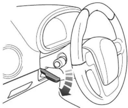
Line drawing of a car interior showing steering wheel, dashboard, and steering wheel (no text or symbols)T oadjusttheangleofthesteeringcolumntosuityour drivingposition:
I Fullyreleasethelockinglever.
2Holdthesteeringwheelinbothhandsandtiltthe steeringcolumnupordowntomovethewheelinto themostcomfortableposition.
3Onceaccomfortabledrivingpositionhasbeenselected, pullthelockingleverfullyuptolockthesteering columnintoitsnewposition.
INSTRUMENTSANDCONTROLS
Horn
natural_image
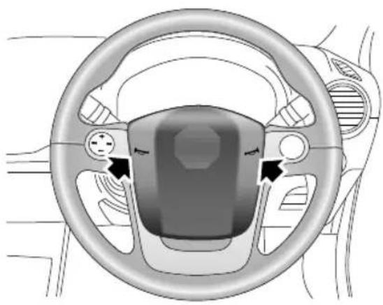
Interior view of a car steering wheel and dashboard (no text or symbols visible)pleaseensurethatyoupressinthisareatoavoidany potentialconflictwiththeoperationoftheairbag.
Pressthesteeringwheelpadwherearrowedtooperate thehorn.
Note: The vehicle horn switch and the driver's airbag are located in close proximity on the steering wheel. The illustrations show the position of the horn switch,
INSTRUMENTSANDCONTROLS
Mirrors
DoorMirrors
Note: Objectsviewedinexteriormirrorsmayappear furtherawaythantheyactuallyare.
MirrorGlassElectricAdjustment *
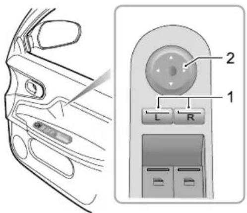
Withtheignitionswitchedon,pressleft(L)orright(R) switch(1)toselecttheleftorrightmirror.Theswitch illuminates.Then,pressoneofthe4arrowsontheround switch(2)toadjusttheangleofthedoormirror.
IMPORTANT
•Theexteriormirrorsareoperatedwiththeelectric switch,operatingthemirrordirectlybyhandmay resultinthefailureofrelatedequipments.
- Exteriormirrorsareoperatedwithmotors. Therefore,flushingwithhighpressurewaterjets directlyinthecarwashmayresultinthefailureof theelectricdevice.
INSTRUMENTSANDCONTROLS
MirrorGlassManualAdjustment \*
natural_image
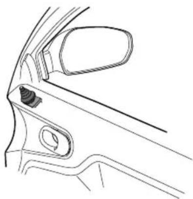
Technical line drawing of a car front panel showing handle, side mirror, and mounting bracket (no text or symbols)Usethejoysticktoadjustthemirrorglasstoachievethe requiredview.
HeatingElements \*
Thedoormirrorshaveintegralheating
elementswhichdisperseiceormistfromtheglass.The heatingelementsoperatewhiletheHeatedRearWindow isswitchedon.
Note: The heating elements will only work when the engine is running.
INSTRUMENTSANDCONTROLS
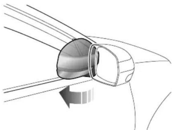
MirrorFolding
natural_image
Diagram of a car's side mirror and intake manifold, showing airflow direction (no text or symbols)Themirrorscanbefoldedbackmanuallytowardsthe sidewindowsintoa'park'positiontoenablethecarto negotiatenarrowopenings.
InteriorRear-viewMirror
Beforedriving, adjustthebodyofthemirrorbyhandto achievethebestpossibleviewtotherear. Themanual dippingfunctionoftheinteriorrear-viewmirrorhelpsto reduceglarefromtheheadlightsoffollowingvehiclesat night.
ManualMirror

natural_image
Side mirror with a black arrow pointing to the side, mounted on a curved line (no text or symbols)Movetheleveratthebaseofthemirrorforwardto'dip' themirror.Normalvisibilityisrestoredbypullingthelever backagain.
INSTRUMENTSANDCONTROLS
Note: In some circumstances, the view reflected in
'dipped'manualmirrorcanconfusethedriverastothe
preciselocationoffollowingvehicles.
INSTRUMENTSANDCONTROLS
SunVisor

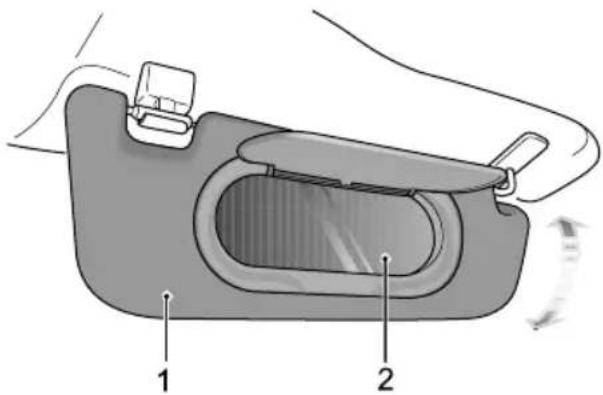
Thevanitymirrorforthedrivershouldonly beusedwhenthevehicleisstationary.
natural_image
Diagram of a car interior showing a lid and handle, with numbered parts labeled 1 and 2 (no text or symbols beyond labels)Pivotthesunvisor(Figure1)downwardtoaccessthe vanitymirror * (Figure2).Somemodelsrequirethecover tobeliftedtoaccessthemirror.
INSTRUMENTSANDCONTROLS
Windows
PowerOperatedWindowControls
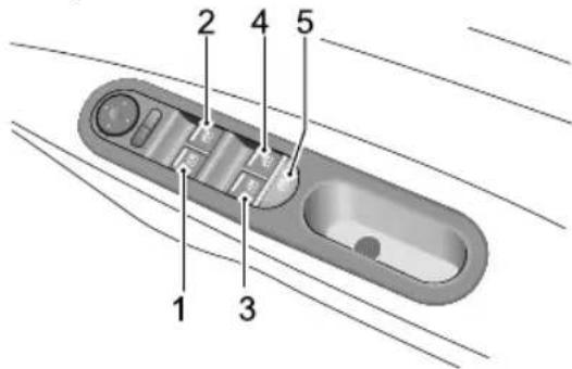
1FrontLeftWindowSwitch
2FrontRightWindowSwitch
3RearLeftWindowSwitch
4RearRightWindowSwitch
5RearWindowIsolationSwitch
WindowOperation

Ensurechildrenarekeptclearwhenraisingor loweringawindow.
Pushtheswitch(1-4)downtolower,andpulltheswitchup toraisethewindow.Thewindowwillstopmovingassoon astheswitchisreleased(unlessthe'One-T ouch'function isactive).
Note: The front and rear passenger windows can also be operated by individual window switches, mounted oneachdoor. Therear window switches will not operate if therear windowisolations switch has been activated.
Note: The electric windows can be operated with the ignition in position / or // (Forsafety: door should be closed).
RearWindowIsolationSwitch
Pressthebutton(5)toisolatetherearwindowcontrols (anindicatorlightinthebuttonilluminates),pressagainto restorecontrol.
INSTRUMENTSANDCONTROLS
Note:ItisrecommendedthatyouISOLATEtherear windowswitcheswhencarryingachild.
'One-T ouch'Down\*
Bybrieflypressingandthenreleasing(withinhalfasecond)awindowswitch,thewindowcanbefullyopened. Windowmovementcanbestoppedatanytimebypassing theswitchagain.
Note: DONOToperatetheswitchformorethan20 secondssoastoprotectthemotorfromoverheating, theswitchwillnotoperate. If this occurs, please wait until themotorcoolsdown.
INSTRUMENTSANDCONTROLS
InteriorLights
InteriorLamp
natural_image
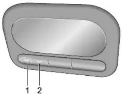
3D diagram of a device with labeled parts (1 and 2), no text or symbols presentNote: Manualoperationisactiveonlywhenthe ignitionswitchedisinposition I or2.
AutomaticOperation
Theinteriorlightilluminationoccursautomaticallywhen thedoorisopened. Theinteriorlightremainsilluminated forapproximately30secondsafterthedoorsareclosed.
ManualOperation
Pressthebutton1 toswitchtheinteriorlighton, pressthe button2 toswitchchofftheinteriorlight.
INSTRUMENTSANDCONTROLS
CentreConsolePowerSocket
natural_image
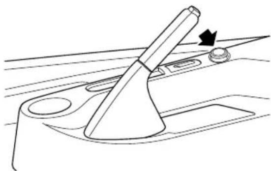
Line drawing of a mechanical lever mechanism with a handle and pivot point (no text or symbols)Thecentreconsolepowersocketislocatedonthecentre console(asshownabove),removetheplugtoexposethe centreconsolepowersocket.
Note: The centreconsolepowersocketvoltagesupply is 12V, and theratedpoweris 120w.
INSTRUMENTSANDCONTROLS
StorageEquipment
Instructions
- Pleasecloseallstorageboxeswhenthevehicleis running.Leavingthesestorageboxesopenmaycause personalinjuryintheemergencystart-off,hardbrake andcaraccident.
- Donotplaceinflammablesordisposablecigarette lightersinanystorageboxes. Thehightemperature insummermayignitetheinflammablesanddisposable cigarettelighters,resultinginfires.
Glovebox
natural_image
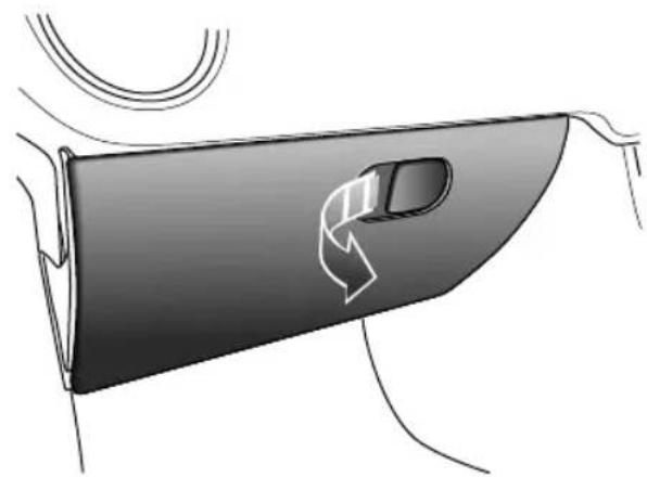
Diagram of a car door handle with a curved arrow indicating clockwise motion (no text or symbols)Pullthehandletoopentheglovebox.
T oclosetheglovebox,raisethelidandpushtoclose. Ensurethegloveboxisfullyclosedwhenthecarismoving.
INSTRUMENTSANDCONTROLS
StorageBox
InstrumentPanelStorageBox

DONOTputflammablesubstancesorliquids intheinstrumentpanelstoragebox.Ensure thestorageboxisfullyclosedwhenthecaris moving.
natural_image
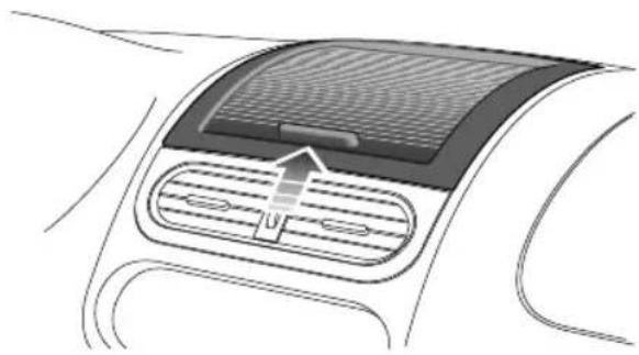
Top-down view of a car's front air vent showing airflow direction (no text or symbols)Pushtheinstrumentpanelstorageboxcoverupwardto open.
Pulltheinstrumentpanelstorageboxcoverdownwardto close.
FrontPassengerLowerStorageBox \*
natural_image
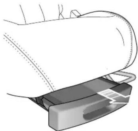
Technical illustration of a mechanical assembly with a clamped component (no text or symbols)T oopen, gently lift the handle and pull forward.
T oclose, push the handle backward.
INSTRUMENTSANDCONTROLS
CupHolder

DONOTplaceopencupsinthecupholder.
Whenthecarisinmotion, the hot drinks may spill and cause injuries.
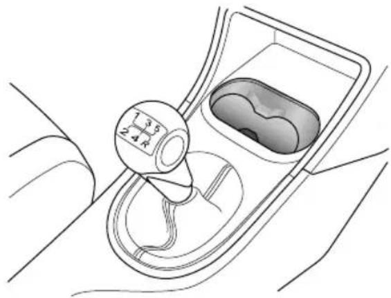
natural_image
Diagram of a car gear shift lever with numbered slots (1-5) and a central hub (no text or symbols)Locatedatthefrontofthegearleveristhecupholderfor user.
ClimateControl
50ClimateControl
CLIMATECONTROL
ClimateControl
Ventilation
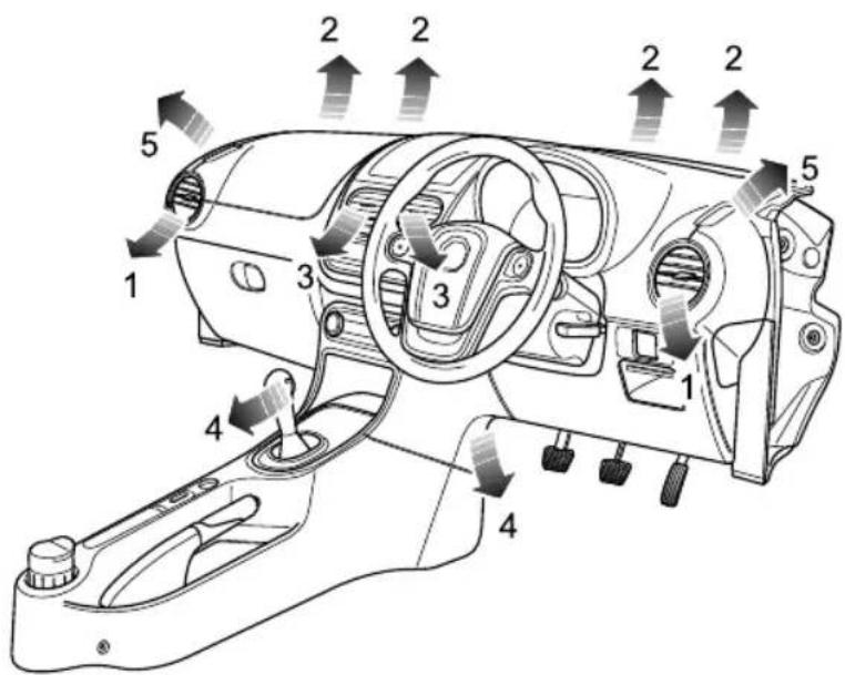
|Sidevents
2Windscreenvents
3Centrevents
4Frontseatfeetvents
5Frontsidewindowvents
Heating, ventilation and air conditioning system provides fresh or heated air to the interior of the car from the air intake grille in front of the windscreen.
Alwayskeeptheairintakegrilleclearof obstructionssuchasleaves,snoworice.
Airoutletsareprovidedtothe windscreen,faceandfeet-thelocation ofthoseventsisshownintheillustration.
Particle/PollenFilter
Theparticle/pollenfilterhelpstokeepthecarinteriorfree frompollenanddust. T oremainfullyeffective,thefilter shouldbereplacedattherecommendedserviceinterval.
Vents
CentreVents
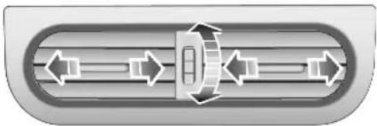
natural_image
Diagram of a vehicle with directional arrows indicating flow or movement (no text or symbols)Rotatethethumb-wheeldowntocloseoruptoopenthe vents.Directtheairflowbymovingthecontrolinthe centreofthelouvres.
Note: Toincreaseoutputfromthecentrevents, shut thesidevents.
SideVents
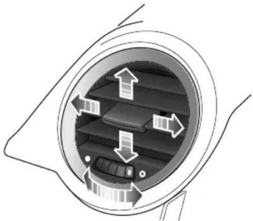
natural_image
Diagram of a car interior showing airflow or traffic direction (no text or symbols)Rotatethethumb-wheellefttocloseortotherightto openthevents.
Directtheairflowbymovingthecontrolinthecentreof thelouvresupordown,orfromsidetoside.
Note: Toincreaseoutputfromthesidevents, closethe centrevents.
CLIMATECONTROL
HeaterControls \*
ControlPanel
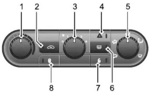
IT emperaturecontrol
2Airrecirculation
3Blower
4Hazardwarninglight
5Airdistribution
6Heatedrearscreen
7Interiorlockunlocking
8Interiorlocklocking
Blower
Rotatetheblowercontrolclockwisetoincreasethe blowerspeedorrotateanti-clockwisetodecreasethe blowerspeed. Theblowerisswitchedoffwhentheblower speed and blowerspeedincrease gradually from 1 to 4.
T emperatureControl
RotatetheTEMPcontrolclockwisetoincreasetheair temperatureinsidethecarorrotateanti-clockwiseto decrease.
AirDistribution
Rotatetheairdistribution,controltoselecttherequired airdistributionmode.

For'face'.Directsairtothesideandcentre
vents.

For'face+feet'.Directstheairtothefeet,sideents.

For'feet'.Directsairtothefeetvents.
Note: In this mode, asmall amount of fair will be directed to the beside and windscreenvents.

For'feet+windscreen'.Directsairtothe
windscreenandfeetvents.
Note: In this mode, asmall amount of fair will be directed to the beside events.

For'windscreen'.Directsairtothewindscreen
vents.
Note: In this mode, asmall amount of fair will be directed to the beside events.
HeatedRearScreen

Theheatingelementsontheinsideoftherear screenareeasilydamaged.DONOTscrape orscratchtheglass.DONOTsticklabels overtheheatingelements.

Presstöoperate;theLEDintheswitchwill
illuminateindicatingtheheatedrearscreenisswitched on.TheLEDextinguisheswhentheheatedrearscreen isurnedtheatedeascreewiswitchoff automaticallyafter 15minutes.
Note: The heatedrearscreenwillonlyfunctionwith theengineoperating.
CLIMATECONTROL
AirRecirculation
Presstöoperate, theLEDintheswitch
illuminates, the air insidethe caris recirculated and the air intake is closed, preventing the entry of traffic fumes.
Whentheengineisoff, theairrecirculationcontrolflap staysincurrentposition.
Note: Leaving the system in recirculation mode can cause the windscreentomist. If this happens, switch offrecirculation and turn the control maximum demisting.
CLIMATECONTROL
AirConditioningControls \*
ControlPanel
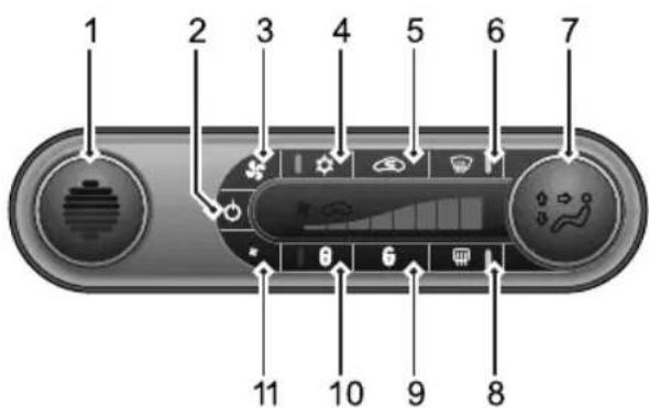
IT emperaturecontrol
2Poweron/off
3Increaseblowerspeed
4A/Con/off
5Airrecirculation
6Defrost/Demist
7Airdistribution
8Heatedrearscreen
9Interiorlockunlocking
10Interiorlocklocking
I I Decreaseblowerspeed
Blower

Pressthebuttonincreaseblowerspeed.
Whether systerswitched, pressing button operates the system.

Preshebuttonodecreaseblowerspeed.
Whether system switched, pressing button operates the system.
CLIMATECONTROL
T emperatureControl
Rotating the temperature control clockwis will increase the air temperature. The controldisplay will gradually changetored. Whent the temperature control is fully increased, the controldisplay will be totally red.
Rotating the temperature control anti-clockwise will decrease the air temperature. The controldisplay will gradually changet blue. Whent the temperature control is fully decreased, the controldisplay will betotally blue.
A/CButton

PresstheA/CButtontoswitchtheair
conditioningsystemon.Pressagaintoswitchoff.
Note:
I Theairconditioningsystemcanonlybeswitched onaftertheengineisstarted;
2When the air conditioningsystem is switched off, the system can still provide heating and ventilation function.
3WhentheAirconditioningisswitchedon,the compressorwillturnitself"on"and"off".
PowerOn/Off

PresthPoweon/offbuttonswitchhe
systemoffandpressagaintoswitchon.
Not Recirculation status will remain the setting selected.
AirDistribution
Rotatetheairdistribution,controltoselecttherequired airdistributionmode.

FolfaceDirectaircheidandentre
vents.

For'face+feet'.Directsairtothefeet,side
andcentrevents.

For'feet'.Directsairtothefeetvents.
Note: In this mode, asmall amount of fair will be directed to the beside and windscreenvents.
For'feet+windscreen'.Directsairtothe
windscreenandfeetvents.
Note: In this mode, as small amount of fair will be directed to the beside events.

For'windscreen'.Directsairtothewindscreen
vents.
Note: In this mode, asmall amount of fair will be directed to the beside events.
Themodesare'face'-face+feet'-feet'-feet+windscreen'-windscreen'clockwiseinorder.T omake furtherselectionsturncounter-clockwise.
Defrost/Demist

With this buttonpressed, air conditioning
isswitchedon,theblowerissettomaximumspeed, airdistributionissettowindscreEnoswitchoff defrost/demist,pressthebuttonagain.
HeatedRearScreen

Theheatingelementsontheinsideoftherear screenareeasilydamaged.DONOTscrape orscratchtheglasDONOTsticklabels overtheheatingelements.
Presstöoperate;theLEDintheswitchwill
illuminateindicatingtheheatedrearscreenisswitched ofTheLEDextinguisheswhentheheatedrearscreen isturnedoftheheatedrearscreenwillswitchoff automaticallyafter 15minutes.
NoteThe heated ascreenwilbnlfunctionwith thengineoperating.
CLIMATECONTROL
AirRecirculation
Withthisbuttonpressed,theiconshowsin
thedisplay, theairinsidethecarisrecirculatedandtheair intakeisclosed, preventingtheentryoftrafficfumes. Press thebuttonagain, thesystementersexternalcirculation
Whentheengineispoweredoff, theairrecirculation controldoorstaysincurrentposition.
Note: Use this function to obtain maximum air conditioning performance and optimum fuel efficiency when A/Cisoperating.
AudioSystem
60CDPlayer * (LowLine)
70CDPlayer * (HighLine)
AUDIOSYSTEM
CDPlayer \* (LowLine)
UseInstructions
I Whencleaningthevehicle,ensurethatwaterdoesnot contacttheaudiosystem.
2Useasoftclothtocleanthedisplay.Usealcohol toremovestubborndirt.Donotusewater,solvent orabrasivecleaner,thesesubstanceswilldamagethe display.
3Donotattempttoplaynonstandarddiscs,orany shapewhichisnotround.Donotusedamageddiscs orplaceanyothermaterialintotheCDslot.
4Theaudiosystemisdesignedtooperatebetween the temperaturesof-20°Cand+70°C.
5Whentravellingonroughorunevenroads, disc reproductionmaybeimpaired.
6Distortion, interference and lack of signal clarity, are often attributed to a fault in the radio. Problem of this kind are usually caused by atmospheric conditions, signal strength, hilly terrain, tall buildings, bridges and even electrical interference from power lines.
7TheUSBinterfaceoftheplayerdoesnotsupporta portableharddrive.
8TheUSBinterfacecansupportsometypesofcard readers, but we are unable to guarantee that it supports all types of cardreaders.
9TheUSBinterfaceofthisplayerdoesnotsupporta USBconcentratorconnectionandextendedharness.
10TheUSBinterfaceofthisplayermaynotrecognize allUSBbrandsandtypes,andsomefilesmaynotbe playedcorrectly.Insuchcases,pleasecontactyour MGAuthorisedRepairer.
IMPORTANT
OnlyusetheCDplayerwhenroadconditionspermit.
CDPlayerControlPanel
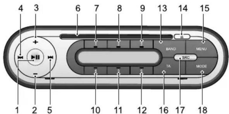
On/OfbPause/Mute
VolumeDown
VolumeUp
(See Downward)
(Seek upward)
6DSlot
PreseButton
ReseButton2
PreseButton3
IReseButton4
IPreseButton5
IPreseButton6
IBAND(Frequency)
(CIEj▲Button)
IMENU
ГБА(TrafficAnnouncement)
ISRC(Source)
18ODE
AUDIOSYSTEM
BasicOperation
On/OffPower
PresstheOn/Offbuttontoswitchonradiosystem, and pressagaintoturnoffthesystem.
When the CD player is off, and a CD is loaded, the CD player will switch on.
30MinutesPlayFunction
Whentheignitionisswitchedoff, press the On/Offbutton to operate the audiounit for up to 30 minutes, after 30 minutesthe player will switch off. T o switch on again, press the On/Off button.
Mute/Pause
PresstheMUTEbuttontomutetheradio.Pressagainto resumeplay.
IfinCD/USBmode, presstheMutebuttontopause.
SelectMode
RepeatedlypresstheSRCbuttontochangetresource oftheoutput. The unit will cycle through the following options: TUNER, CD (if there is adiscin the CD player), USB (if USB is connected), and AUX.
Note: CDplaycanonlybeselectedwhenthereisa discintheCDplayer.
Note: USBcanonlybeselectedwhenaUSB/bluetooth sourceisconnected.
VolumeAdjustment
PressVolumeDownbutton, thevolumewilldecreaseby -1, ifpressandholdthebutton, thevolumewilldecrease quicklyto0.
PresstheVolumeUpbutton, thevolumewillincreaseby +1, ifpressandholdthebutton, thevolumewillincrease quickly to 30.
MenuOperation
ForeachpressofMENUbutton, themodewillcycle throughClock, BASS, TREBLE, BALANCE, FADER, EQ, LOUDNESS, AF, REG, CT, EON and TA Volume.
BASS
InBASSmode, pressbuttonorbuttontadjustthe basseffect(adjustmentrange:-7-+7).
TREBLE
In TREBLEmode, pressbuttonorbuttontadjust thetrebleeffect(adjustmentrange:-7-+7).
BALANCE
InBALANCEmode, press 🏠 buttobotto to adjust the left-right balance effect (adjustment range: L7-R7), '0' represents the left-right speaker balance.
FADER
InFADERmode, postadjust to adjust thefront-rearbalance effect (adjustment range: F7-R7), '0'represents the front-rearspeaker balance.
EQ
InEQmode, piastototon, and select from CLASSIC, ROCK, POPULAR, and OFF.
LOUDNESS
InLOUDNESSmode, pressbook to stop/starttheloudnesscontrol.

AlternativeFrequenciesSetting
Press buttonorbctontoselectAFONorAFOFF. IftheradiostationselectedsupportsAFanditssignal becomesweak,thenthe Tunershouldbeswitchedtothe strongestavailablefrequency.
RegionSetting
PressButtonorbuttontoselectREGONorREG OFF.
Note: AFshowsthattheRDSistuningtothestrongest signalforthestationyouhaveselected.Itreturnstoa differentfrequencywhenyoumoveintoanotherarea.
AUDIOSYSTEM
ClockTimeSetting
PressbuttonorbuttontoselectCTONorCTOFF.
Note: CTsynchronisation(viaRDS) will be automatically deactivated if the user makes manual changestotheclockordate.
EnhancedOtherNetworksSetting
PressButtonorbuttontoselectEONLOorEON DX.
TrafficAnnouncementVolume
PressbuttonorbuttonebadjustTAvolume.
TimeSetting
PressMENUbuttontoentertheclockdisplay,press andholdMENUbuttontoentertheclocksettingmode, andthenpressMENUbuttontoaccessthehour-clock, minute-clock,timedisplaymodes(12HRor24HR),and clockdisplayprotection(openorclose),pressbutton or buttonomakeselection
PlayingMode
InCD/USBmode, pressMODEbutton to select the random or repeat playing modes.
Inrandommode, pressbuttonorbuttonandselect tocloseoropenrandommode.
Notrepeatplayisnotrequired,pressMODE buttontwicetoconfirmtheselectedrandommode.
Inrepeatmode, pressor selects single track, folder or close.
Note: If the track has no corresponding information the information will not be displayed.
Note: If there is no folder in source, therandom folder cannot be used.
FolderMode
WheninCD/USB,pressandholdMODEbuttonontoenter thefolderselectionmode,andpressor buttontoselectthefolderforwardorbackward.
Note:4secondsafterthelastoperationhasbeen made,thesystemwillenterthecurrentplayingmode.
RadioFunction
ModeSelection
PressSRCbuttontoselectradioasthesource.
BandSelection
RepeatedlypresstheBANDbuttontoselectFMI,FM2, FMA,MW,MWAfrequencies.
Note: Iftheradioisinstereo, thebottomofthescreen will display 'ST'.
T une
Thereare3tuningmodes, which are these archtuning, manual tuning and pre-settuning.
SearchTuningMode
pressbuttonorbutton,theradioautomatically searchsthefrequencyrange,lookingforaradiostationof acceptablestrength.Onceastationisfound,thatstation willbeplayed.
AUDIOSYSTEM
Note: Ifnostationcanbefound, thenthesearchwill bestopped, and thescreenwilldisplay 'NOSTATION'.
ManualTuningMode
Pressandholdeitherofthe buttonandbutton,and thenenterthemanualtuningmode,andpressbuttonorbuttonagaintosearchstations.
Note: if noselectionism made after 5 seconds manual tuning will be cancelled.
Pre-setTuningMode
Upto30radiostationscanbestored(FM1,FM2,FMA, MW,MWA).PressnumberbuttonsI-6toselectastored frequency.
StoreStation
Therearemanualandautostoremodes.
ManualStore
- PressBANDbuttontoselectthedesiredwaveband.
- Usesearch,manualorpre-settuningmodestotuneto thedesiredstation.
- Pressanynumberbuttonformorethan2seconds. The frequencieswillbeautomaticallystored.
Note: Manualstoreoverwritesanystationswhich alreadystoredonthepre-setbuttons.
AutoStore
- PressBANDbuttontoselecttheFM/WMfrequency.
- PressandholdtheBANDbutton, Auto-storescans thewavebandtofindthesixstrongestFM/WMradio frequenciesandthenstorestheminFMAorMWA memoryinorderofthesignalstrength.
Ifauto-storeisunabletofindsixstrongstations,the remainingpre-setsarenotused.
No automatistorageoverwritingations alreadystoredontheASTpre-setbuttons.
TA(TrafficAnnouncement)
Press TAbuttontoenable TAfunction,iftheradiois on,theplayerwillsearchautomatically.ifcurrentstation doesn'tsupportTA,presstheTAbuttonagaintodisable TA.WhenaTAisreceivedduringCD/USB playback,the MIXfunction(ifselected)iscancelled.
CDPlaying

TheCompactDisc(CD)playerfittedtoyour carwillonlyacceptonediscatatime.
LoadingaCD
Makesurethatthediscispositionedwiththelabel sideupwards,thengentlypushitintotheslotuntilthe mechanismdrawsthediscinfully.CDplaywillstart immediately.
T rackSearch
I Pressbutton noncetoskiptothebeginningofthe nexttrack.
2Ifthetrackelapsedtimeismorethan1 seconds,Press buttononcetoreturntothestartofthecurrent trackandpressagaintostarttheprevioustrack.If elapsedtimeislessthan3seconds,press button oncetoreturntotheprevioustrack.
FastForward/Rewind
1 Pressandholdbuttontofastrewind. 2 Pressandholdbuttontofastforward.
EjectingCD
PressEjectbutton, thediscwillbeejectedfromtheplayer andcanthenberemoved.
AUDIOSYSTEM
USB
USBConnection
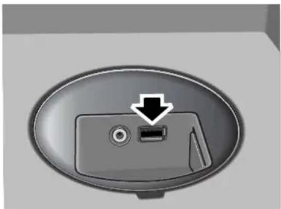
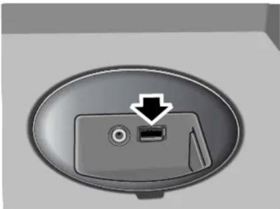
AUSBconnectionissituatedinsidethecentreupper stowagetraylocatedinthefascia.
InsertaUSBmemorystickviatheUSBconnection.
natural_image
Top-down view of a car intake tray with a white arrow pointing to a small electronic component (no text or symbols)USBPlaying
Pressbuttononcetochoosethenexttracktoplay.
Press buttononce,iftheplayingtimeexceeds l second, thetrackwillbeplayedfromthebeginning,pressthe buttonagaintoselecttoplaythepreviousrack;ifthe playingtimedoesnotexceed l second,press once,toplaythepreviousrack.
Note: This system can only play.mp3 and .wma format files.
USBRemoval
DonotforciblyremovetheUSBwhenUSBfilesare displayed, this may cause file damage.
AUX
AUXInputPlaying
AnAUXdeviceconnection(3.5mmjacksocket)islocated insidethecentreupperstowagetraylocatedinthefascia.
Insertanauxiliarydeviceviatheauxiliarysocket,after auxiliaryisconnected.
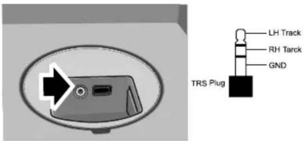
Note: Please use 3.5mm TRSplugsto connect auxiliary audio.
Antenna
natural_image
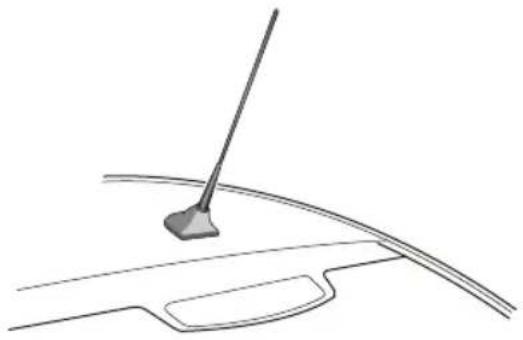
Line drawing of a car's roof and side panel with a antenna (no text or symbols)Theantennaislocatedattherearoftheroof.Avoid bendingtheantenna.Howeverwhenrequired,e.g.when usinganautomaticcarwashingfacility,pleaseensurethat theantennaisremoved.
T oremovetheantennaunscrewtheantennaanti clockwise.
AUDIOSYSTEM
CDPlayer \* (HighLine)
UseInstructions
I Whencleaningthevehicle,ensurethatwaterdoesnot contacttheaudiosystem.
2Useasoftclothtocleanthedisplay.Usealcohol toremovestubborndirt.Donotusewater,solvent orabrasivecleaner,thesesubstanceswilldamagethe display.
3Donotattempttoplaynonstandarddiscs,orany shapewhichisnotround.Donotusedamageddiscs orplaceanyothermaterialintotheCDslot.
4Theaudiosystemisdesignedtooperatebetween the temperaturesof-20°Cand+70°C.
5Whentravellingonroughorunevenroads, disc reproductionmaybeimpaired.
6Distortion, interference and lack of signal clarity, are often attributed to a fault in the radio. Problem of this kind are usually caused by atmospheric conditions, signal strength, hilly terrain, tall buildings, bridges and even electrical interference from power lines.
7TheUSBinterfaceoftheplayerdoesnotsupporta portableharddrive.
8TheUSBinterfacecansupportsometypesofcard readers,butweareunabletoguaranteethatit supportsalltypesofcardreaders.
9TheUSBinterfaceofthisplayerdoesnotsupporta USBconcentratorconnectionandextendedharness.
10TheUSBinterfaceofthisplayermaynotrecognize allUSBbrandsandtypes,andsomefilesmaynotbe playedcorrectly.Insuchcases,pleasecontactyour MGAuthorisedRepairer.
IMPORTANT
OnlyusetheCDplayerwhenroadconditionspermit.
CDPlayerControlPanel
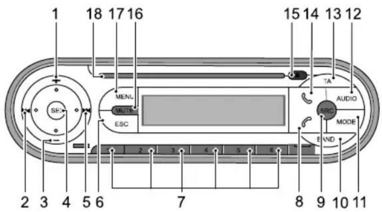
IVolumeUp
2(SeekDownward)
3VolumeDown
SEL
5(SookUpward)
BSC
7NumberButton
8
9SRC(Source)orOn/Off
10BAND(Frequency)
IIMODE
12AUDIO
I3TA(TrafficAnnouncement)
14
15(①EjectButton)
16MUTE
17MENU
18CDSlot
AUDIOSYSTEM
SteeringWheelControlButton
natural_image
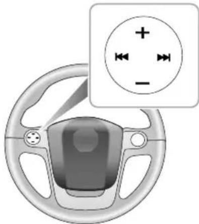
Diagram of a car steering wheel with a circular dial and directional arrows, no text or symbols present.'+'button:volumeup
'-button:volumedown
| (SeekDownward)(SeekUpward) | |||
| Radio | Short Press | Previouspresetin currentBand | Nextpresetincurrent Band |
| Long Press | Previousautomatically searchthefrequency range,lookingfor aradiostationof acceptablestrength. Onceastationis found,thatstationwill beplayed. | Nextautomatically searchthefrequency range,lookingfor aradiostationof acceptablestrength. Onceastationis found,thatstationwill beplayed. | |
| CD/USB /Bluetooth /Audio/lpod /lphone | Short Press | PrevioustrackNexttrack | |
| Long Press | Fastrewind | Fastforward | |
BasicOperation
On/OffPower
PresstheOn/Offbuttontoswitchonradiosystem, and pressagaintoturnoffthesystem.
WhentheCDplayerisoff,andaCDisloaded,CDplayer willswitchon.
30MinutesPlayFunction
Whentheignitionisswitchedoff,presstheOn/Offbutton tooperatetheaudiunitforupto30minutes,after30 minutestheplayerwillswitchoff.T oswitchonagain,press theOn/Offbutton.
Mute/Pause
PresstheMUTEbuttontomutetheradio.Pressagainto resumeplay.
IfinCD/USB/bluetoothmode, press the Mutebutton to pause.
SelectMode
RepeatedlypresstheSRCbuttontochangethesource oftheoutput. The unit will cycle through the following options: radio, CD (if there is adiscin the CD player), USB (if USB is connected), Bluetooth audio (if Bluetooth is connected), and AUX.
Note: CDplaycanonlybeselectedwhenthereisa discintheCDplayer.
Note: USB/bluetoothcanonlybeselectedwhena USB/bluetoothsourceisconnected.
VolumeAdjustment
PressVolumeDownbutton, thevolumewilldecreaseby -1, ifpressandholdthisbutton, thevolumewilldecrease quicklyto0.
PresstheVolumeUpbutton, thevolumewillincreaseby +1, ifpressandholdthisbutton, thevolumewillincrease quicklyto30.
AUDIOSYSTEM
AudioSoundSetting
Press the AUDIO button to adjust the sound setting, press button or button to access BASS, MIDDLE, TREBLE, BALANCE, FADER, EQ, and LOUDNESS. Press the SEL button to access and confirm selection.
BASS
InBASSmode, pressbuttonorbuttontoadjustthe basseffect(adjustmentrange:-7-+7).
MIDDLE
InMIDDLEmode, pressbuttonorbuttontendjust thebasseffect(adjustmentrange:-7-+7).
TREBLE
InTREBLEmode, press buttonorbitontoadjust thetrebleeffect(adjustmentrange:-7-+7).
BALANCE
InBALANCEmode, pressbuttonorbutton:adjust theleft-rightbalanceeffect(adjustmentrange:L7-R7), '0' represents theleft-rightspeakerbalance.
FADER
InFADERmode, pressbutonorbuttontoadjust thefront-rearbalanceeffect(adjustmentrange:F7-R7), '0'representsthefront-rearspeakerbalance.
EQ
InEQmode, pressbuttonorbuttontoselectfrom CLASSICAZZPOPROCKFLATVOCALandOFF.
LOUDNESS
InLOUDNESSmode, pressbook to stop/starttheloudnesscontrol.
Clock, TimeandDate
PressMENUbuttontoenter,selectClockandDate,pressSELbuttontoenterthedateandtimesettingmenu.Press the buttontoenterchosethesub-menu and pressSELtoaccess.
ClockorDateMode
PressSELbuttontoaccessclockmode, pressthe buttontoaccesshour-clock, minute-clock

andtimedisplaymodes(12HRor24HR).PressSELbutton toconfirm,pressSELbuttonagaintoreturntothemenu afterClockSettingshavebeenconfirmed
PressSELbuttontoaccessdatemode, pressthe button or buttontoaccesstheday, month, year. PresstheSEL buttontoselect, pressSELbuttonagaintoreturntothe menuinterface.
PlayingMode
WheninCD/USBmode, pressMODEbuttontoselect Random, or RepeatandDisplayInformation.
Wheninrandommode, pressbuttonorbuttontoselectRandomAll, RandomFolderorRandomOff.
Wheninrepeatmode, pressbuttonorbuttonto selectRepeatTrack, RepeatFolderorRepeatOff.
WheninDisplayInformationmode, pressbutton ▶ buttontosearchFolderNo, TrackNo&SongElapsed Time, ArtistName, AlbumName.
Note: If the track has no corresponding information, the information will not be displayed.
Note: If there is no folder in source, therandom folder selection is unavailable.
FolderMode
WheninCD/USBmode, pressandholdtheMODEbutton toenterthefoldermode, and printoblock to select folder, press theSELbuttontoconfirm, and start to play the first track within these selected folder.
Notdecondefterthlasoperationabeen made,thesystemwillenterthecurrentplayingmode.
AUDIOSYSTEM
MenuOperation
PresstheMENUbuttontoaccessthemenumode.Press buttonorb MontoselectRDSSettings,Bluetooth Settings,ContrastAdjustments,DABSetting.
RDSSettings
Inthemenumode, selectRDSSettings, ClockandDate, and press the SEL button to enter the RDS settings menu. Press button to select AP, REG, CT, EON, TAVolume.
AlternativeFrequenciesSetting
PressButtonorbuttonCloselectAFONorAFOFF, pressSELbuttonontoconfirm.
IftheradiostationcurrentlyselectedsupportsAFandits signalbecomesweak,thentheradioshouldswitchtothe strongestavailablefrequency.
RegionSetting
PressButtonorbuttonObselectREGONorREG OFF,pressSELbuttonontoconfirm.
WhenREGison,theradiocanchangethefrequencyinthe AFlistthestation.WhenREGisoff,theradiowilltuneto anotherstation.
ClockTimeSetting
PressbuttonorbuttontoselectCTONorCTOFF, pressSELbuttonontoconfirm.
If the current selected station carries CT information, the time of the support will synchronise automatically via RDS if CT ON.
EnhancedOtherNetworksSetting
PressbuttonorbuttontoselectEONLOorEON DX, pressSELbuttonontoconfirmtheEONmode.
TrafficAnnouncementVolume
Press buttonorbuttonadjustTAvolume,press SELbuttonontoconfirm.
BluetoothSettings
Inthemenumode, selectBluetoothSettings, and press the SELbutton to enter the Bluetooth Settings menu. Press button or button to select bluetooth function.
BluetoothActivation
Press buttonorbitontoselectBluetoothONor BluetoothOFF, pressSELbuttonontoconfirm.
BluetoothPairing
BluetoothdevicenameandBluetoothpairingpasswordcan beviewed.
PairedList
T oviewarecordofthelast5T elephonesPairedwiththe vehicle,Press buttonorbontomakeaselection fromtherecord.
PressSELbuttontoapairedphoneandenterthenext submenu.Press buttonorbuttontoManually connect,Syncphonebook,Deleterecords.
IncomingCallvolume
Setsthecallvolume.
ContrastAdjustment
Press buttonorbitontoadjustthecontrast, press SELbuttontoconfirm.
DABSetting
DABStationListOrder
PressButtonorbuttonselectList:Alphabetical oListEnsemble, presSELbuttonconfirm.
ServiceFollowing
PressButtonorbuttonCloselectServiceFollowingONServiceFollowingOFF, pressButtono confirm.
DABBackgroundScan
PressButtonorbuttonReselectBackgroundScan ONBackgroundScaOFF, pressButtono confirm.
AUDIOSYSTEM
FM/MW
ModeSelection
PressSRCbuttontoselectradio.
BandSelection
RepeatedlypressBANDbuttontoselectFMI, FM2, FMA, MW, MWADABI, DAB2, DAB3 bands.
Note: Iftheradiostationisinstereophonicsound, the screenwilldisplay'ST'.
T une
Thereare3tuningmodes, which are these archtuning, manual tuning and pre-settuning.
SearchT uningMode
Pressbuttonorbutton,theradioautomatically searchesthefrequencyrange,lookingforaradiostationof acceptablestrength.Onceastationisfound,thatstation willbeplayed.
Note: Ifnostationexistswithintheentireband, then thesearchwillbestoppedafterfinishingacycle, and thescreenwilldisplay'NOSTATION'.
ManualTuningMode
Pressandholdeitherof buttonorbiton,andthen enterthemanualtuningmode,andpressbuttonor buttonagaintosearchstations.
Note:5secondsafterthelastbuttonpress,thesystem willleavethemanualtuningmode.
Pre-setTuningMode
6stationscanbestoredineveryfrequency.Pressnumber buttons l-6toselectastoredfrequency.
StoreStation
Manualstoreandautostoremodes.
ManualStore
- PressBANDbuttontoselectthedesiredwaveband.
- Usesearch,manualorpre-settuningmodestoselect thedesiredstation.
- Pressanynumberedbuttonformorethan2seconds. Thecurrentradiofrequencywillbeautomaticallystored inthepre-setmemory.
Note: Manualstoreoverwritesanystationsalready storedonthepre-setbuttons.
AutoStore
- PressBANDbuttontoselecttheFM/WMfrequency.
- PressandholdtheBANDbutton, Auto-storescans thewavebandtofindthesixstrongestFM/WMradio frequenciesandthenstorestheminFMAorMWA memoryinorderofthesignalstrength.
Ifauto-storeisunabletofindsixstrongstations,the remainingpre-setsarenotused.
Note: Automatic storage overwrites anystations already stored on the AST pre-set buttons.
RDSInfo.
Inradiomode, if the current selection is an RDS station it will display the station names (PSname) and frequency.
PressMODEbuttontoentertheRDSselectionscreen, pressthe buttonbuttonselectRDSTXTdisplay, pressSELtoconfirmandreturntotheFMdisplay.When theradiostationcarriesRDSTXTtheinformationwillbe displayedasrollingtextwithinthedisplay.
TA(TrafficAnnouncement)
PressAttopediatraffic Announcement)function,theradiowillsearchoncevery5secondsforinformation.PresstheTAbuttonagainto close.
AUDIOSYSTEM
DAB\*
PresstheBANDbuttonandselectDABmode,thereare 3DABbands(DABI,DAB2,DAB3).
StationSelect
DABhasthreemodes:EnsembleMode.Alphabetical Mode.Pre-setT uningMode
EnsembleMode
PressMENUbutton,selectandchooseEnsembleMode.
DABradiostationsarefoundwithinanensemble,thiswill containanumberofradiostationsdependentonsignal strength.
Presstheseekbutton
ortresearchforaradio
stationcontainedwithinanensemble,whenalltheavailable stationshavebeenaccessedtheaudiounitwillselectthe nextensemble.
AlphabeticalMode
PressMENUbutton,selectandchooseAlphabeticalMode.
InAlphabeticalModepressthesekbuttonorto <<▶▶▶▶▶▶▶▶▶▶▶▶▶▶▶▶▶▶▶▶▶▶▶▶▶▶▶▶▶▶▶▶▶▶▶▶▶▶▶▶▶▶▶▶▶▶▶▶▶▶▶▶▶▶▶▶▶▶▶▶▶▶▶▶▶▶▶▶▶▶▶▶▶▶▶▶▶▶▶▶▶▶▶▶▶▶▶▶▶▶▶▶▶▶▶▶▶▶▶▶>
Pre-setT uningMode
Sixradiostationscanbestoredwithintheaudiounit. selectbutton1-6toaccessastoredfrequency.
StoreStation
Thereismanualstoremode.
ManualStore
PresstheBANDbuttontoselectthedesiredwaveband.
Usesearch, EnsembleModel, AlphabeticalModeor Pre-set Tuning Modetotune into the desired station.
Pressanynumberbuttonformorethan2seconds. The frequencieswillbeautomaticallystored.
NotManualstoreoverwritesanystationsalready storedonthepre-setbuttons.
EnsembleandStationListView
WheninDABmodepresstheMODEbuttontodisplay alistofensembleBresstbeekto
cyclethroughtheavailableensembles,pressSELtoconfirm selection.Havingselectedanensemble,pressMODEto displayalistofstationsavailableontheselectedensemble. PressESCtoreturntothepreviouslyselectedstation.
YoucanviewthelistinEnsembleortheAlphabeticalMode.
CDPlaying

TheCompactDisc(CD)playerfittedtoyour carwillonlyacceptonediscatatime.
LoadingaCD
Makesurethatthediscispositionedwiththelabel sideupwards,thengentlypushitintotheslotuntilthe mechanismdrawsthediscinfully.CDplaywillstart immediately.
T rackSearch
I PbestonHcetoskiptothenexttrack.
2Ifthetrackelapsedtimeismorethan3seconds,Press buttononcetoreturntothestartofthecurrent trackandpressagaintostarttheprevioustrack. elapsedtimeislessthan3seconds,putton oncetoreturntotheprevioustrack.
AUDIOSYSTEM
FastForward/Rewind
I Pressandholdbuttontofastrewind, once the buttonisreleasedthetrackwillresumenormalplay.
2Pressandholdbuttontofastforward,oncethe buttonisreleasedthetrackwillresumenormalplay.
EjectingCD
PressEjectbutton,thediscwillbeejectedfromtheplayer andcanthenberemoved.
USB
USBConnection
AUSBconnectionissituatedinsidethecentreupper stowagetraylocatedinthefascia.
InsertaUSBdeviceintotheUSBconnection.
natural_image
Top-down view of a device dial with a black arrow pointing to a button (no text or symbols)USBPlaying
Pressbuttononcetochoosethenexttracktoplay.
Pressbuttononce,iftheplayingtimeexceeds3 seconds,thetrackwillbeplayedfromthebeginning,and thenpressthisbuttonagaintoselecttoplaytheprevious track;iftheplayingtimedoesnotexceed3seconds,then press buttononce,todirectlyplaytheprevioustrack.
Pressandholdbuttonorbuttonofastrewindorfast forward,oncethebuttonisreleasedthetrackwillresume normalplay.
Note: This system can only play.mp3 and .wma format files.
USBRemoval
DonotforciblyremovetheUSBwhenUSBfilesare displayed, asthismaycausefiledamage.
iPod/iPhone®
iPod/iPhone® Connection
OncetheiPod/iPhone ^® isinsertedintotheUSBsocket, Track playback will start immediately.
thePod/iPhone ^® has already been connected and details are stored in the player, thenthelast known track and position will be played.
iPod/iPhone® PlayingMode
PresMODEButtonselectRandomRepeatand DisplayInformation.
Press 🏠️ butbontomtomakeanyfurther selection.
Note: Formoreinformation, refertothesection 'Basic Operation' in 'PlayingMode' chapter.
RemovalofiPod/iPhone®
IftheiPod/iPhone ^® has been removed, the CDplayerwill displayontheradiointerface.
AUDIOSYSTEM
AUX
AUXInputPlaying
AnAUXdeviceconnection(3.5mmjacksocket)islocated insidethecentreupperstowagetraylocatedinthefascia.
Insertanauxiliarydeviceviatheauxiliarysocket,after auxiliaryisconnected,thenunitwillplaytheAudio.

Note: Please use 3.5mm TRSplugsto connect auxiliary audio.
Bluetooth
Pairing
TheBluetoothsystemdeviceisnametagged"MG3 CARKIT -*****".
Useyourmobiletelephonetosearchforanavailable Bluetoothdevice.Whenyourtelephonefindsthe"MG3 CARKIT -*****",connect(pair)viathetelephone.
WhenyouarerequestedtoenteraPINcode, input "****" intoyourtelephone.
BluetoothConnection
Beforeusingthebluetoothfunction,pleaseensurethatthe bluetoothconnectionisenabledwithintheaudiounit(see BluetoothSetting,BasicOperation).Itwillbeusedtoa mobilephoneifyourBluetoothenabled.
To access the Bluetooth Function, pleasereferto the chapter, Bluetooth Settings can be accessed via the menu function.
Whenamobilephonehasbeensuccessfullypairedwith theaudiounit.Theaudiounitscreenwilldisplaythatthe phoneisconnected.
IfBluetoothisenabledonthephoneandradiounit(the phoneisinthetop2ofthepairedlist,andnootherdevice isalreadyconnectedtotheunit),thephonewillconnect automatically.
PhoneBookDownload
Onceyourtelephoneisconnected,thesynchronisation phonebookwindowwillbedisplayed,youcanchooseto synchroniseyourphonebookcontacts,(ifyoudon'twant tosynchroniseyourcontactsimmediately,youcanoperate thesynchronisationphonebookfunctioninthephone bookmenulater).
BluetoothMusic
PresstheSRCbuttonandselectBluetoothmusicplay mode,playthetrackonyourmobile.
You can fast-forward and rewind music selections, along with random and repeat play function (not all mobile phones will support this function).
Accept/RejectIncomingCall
Whenreceivingacall,currentaudiostatuswillbepaused, thecallersnumberandnamewillbedisplayed,pressthe buttontoaccessorpressbuttontorejectthecall.
BluetoothFunctionMenu
PressbutontoentertheBluetoothfunctionmenu, pbssdbautontoseleclomCallhistory, Phonebook,Dialnumber,Bluetoothsettings.
CallHistory
PressButtonoccessallistomenif, thephonebookhasnotbeensynchronised,youwillbe promptedtosynchronisencesynchronised,allcall recordscanbeviewed.PresstheSELbuttontoconfirm synchronizationandviewMissedcallIncomingcalls,Outgoingcalls.Pressthe buttonouttoNoselect andpresstheSELbuttontoenterthephonerecords.
AUDIOSYSTEM
Phonebook
PressSELbuttontoaccessthephonebookmenu,press theButtonorbuttontoselectfunctionsfulllistor phonebooksearch.
T osearchthephonebook,pressthebuttoner buttontosearchfornamesorselectthefirstletter,press SELbuttontoconfirm,toenablesearchname.
DialNumber
PresstheSELbuttontoenterthetelephonekeypad,press the buttonorbattontoselectnumbers,pressthe SELbuttontoconfirmselection,press buttonomake atelephonecall.Ifthewrongnumberisselected,select DELandpressSELbuttontodeleteselection.
BluetoothSetting
RefertothechapterofBluetoothSettingswhichisinthe MenuFunction.
Antenna
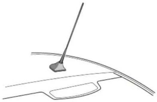
natural_image
Line drawing of a car's roof and side panel with a antenna (no text or symbols)Theantennaislocatedattherearoftheroof.Avoid bendingtheantenna.Howeverwhenrequired,e.g.when usinganautomaticcarwashingfacility,pleaseensurethat theantennaisremoved.
T oremovetheantennaunscrewtheantennaanti clockwise.
Seats&Restraints
88Seats
92SeatBelts
95 AirbagSupplementaryRestraint System(SRS)
103ChildRestraints
SEATS&RESTRAINTS
Seats
CorrectSeatingPosition

Toavoidtheriskoflossofcontroland personalinjury, DONOTadjusttheseats whilethecarismoving.

T akecarewhenadjustingtheheightofthe driver'sseat-thefeetoftherearpassenger couldbecometrappedwhentheseatis lowered.

DONOTallowfrontseatoccupantsto travelwiththeseatbacksreclinedsteeply rearwards. Optimumbenefitisobtained fromtheseatbeltwiththebackrestangle settoapproximately25°fromtheupright (vertical).
Thedriverandfrontpassengerseatsshouldbepositioned asfarrearwardaspractical.Aproperlyadjustedseat helpsreducetheriskofinjuryfromsittingtoocloseto aninflatingairbag.
Ideallytheseatshouldbepositionedsothatthesteering wheelcanbeheldwiththearmsslightlybentandtheseat backinanearlyuprightposition.Makesureyourdriving positioniscomfortableandenablesyoutomaintainfull controlofthevehicle.
SEATS&RESTRAINTS
HeadRestraints

Adjusttheheadrestraintsothatthetopof theheadrestraintisinlinewiththetopof theoccupant'sheadandthebackofthe occupant'sheadisascloseaspossibletothe headrestraint.
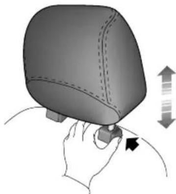
natural_image
Illustration of a person adjusting a seatbelt with directional arrows indicating movement (no text or symbols)Headrestraintsaredesignedtoppreventrearward movementoftheheadintheeventofacollisionor
heavybraking,therebyreducingtheriskofheadandneck injuries.
Pressthebutton(arrowed)andpushtheheadrestraint downwardstoloweritsposition,orlifttheheadrestraint toraiseitsposition.Theheadrestraintcanberemovedby liftingfullyupwards.
SEATS&RESTRAINTS
ManualFrontSeat
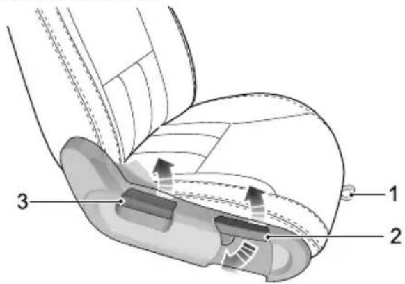
I Forward/rearwardadjustment
2Heightadjustment
3Backrestadjustment
Forward/RearwardAdjustment
Liftthelever(1), slidetheseatintopositionandrelease thelever. Makesuretheseatislockedinpositionbefore driving.
HeightAdjustment \*
Pullthelever(2)upwardswithapumpingactiontoraise theseatasrequired.Pressdownontheleverwitha pumpingactiontolowertheseat.
BackrestAdjustment
Liftthelever(3)andallowtheseattomove,tiltthe backresttothedesiredposition.
SEATS&RESTRAINTS
FoldingtheRearSeats

DONOTcarryobjectsontherearparcel shelf-theycouldbecomedangerous projectilesintheeventofanaccident.
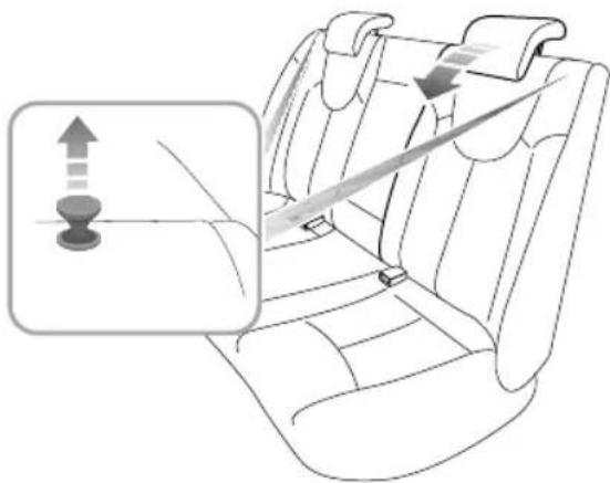
natural_image
Diagram of a car seatbelt with a hand adjusting the seatbelt, showing a finger pressing down (no text or symbols present)DONOTcarryunsecuredequipment,toolsorluggage thatcouldmove,causingpersonalinjuryintheeventof
anaccident, oremergencymaneuver-wherepossible, use theseatbeltstosecureluggagecarriedonseats.
T oincreaseluggagespace,fullylowerallheadrestraints, pullupreleasecatchesandfoldtheseatbackrestforward.
RearSeatBackrests'LatchSecure'Indicators

Ensure that there are seat back rests are securely latched in the upright position when these is in use and when loads are carried in the load space.
When returning these at to the upright position, ensure that the catches are engaged and that the red strip is not visible - this confirm that the back rest is secure.
Note: When returning these at to the upright position, ensure that these at belts are not trapped.
SEATS&RESTRAINTS
SeatBelts
SeatBelts

Theairbagsupplementaryrestraintsystem (SRS)isdesignedtoaddtotheoverall effectivenessoftheseatbelts.Itdoesnot replacethem.SEATBEL TSMUSTALWAYS BEWORN!

Ensure that all seat belts are worn correctly -anim properly worn seat belt increases the risk of death or serious injury in the event of a collision.
Theseatbeltsfittedtoyourvehicleareintendedforuseby adultsizedpersons.Eachbeltisintendedforoneperson only.
IMPORTANT
- DOmakesureallpassengersaresecurelystrapped inatalltimes-evenfortheshortestjourneys.
- ALWAYSadjustseatbeltstoeliminateanyslackin thewebbing.T obefullyeffective,theseatbeltmust remaininfullcontactwiththebodyatalltimes.
• ALWAYSfitthelapstrapaslowonthehipsas possible(neveracrosstheabdomen),andensure thatthediagonalbeltpassesacrosstheshoulder withoutslippingofforpressingontheneck.
• DONOTwearseatbeltsoverhard, sharporfragile itemsinclothing, suchaspens, keys, spectaclesetc. - During pregnancy, women should wear the lapbelt across the hips below the baby.
FasteningtheBelt

DONOTattachanyadditionaldevicetothe seatbeltinanywaywhichmayimpedeits operation.
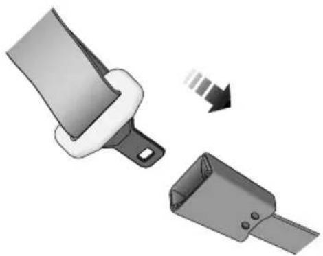
natural_image
Diagram showing a belt buckle being inserted into a separate bracket, with an arrow indicating the process (no text or symbols present)Pulltheseatbeltsteadilyovertheshoulderandacrossthe chestand,ensuringthewebbingisnottwisted,insertthe metaltongueplateintothebucklenearestthewearer.A 'click'indicatesthatthebeltissecurelylocked.
ReleasingtheBelt
Presstheredbuttonontheseatbeltbuckletoreleasethe belt.
CheckingSeatBelts
- Withtheseatbeltfastened,givethewebbingnearest thebuckleaquickpull-thebuckleshouldremain securelylocked.
- Unreelthewebbingtothelimitofitstravel. Check that webbingisfreefromsnagsandcutsandfurthercheck forvisualsignsofwearorfraying. Allowthewebbingto retract, checkingthatretractionissmooth, continuous andcomplete.
- Withthewebbinghalfunreeled, holdthetongueplate andgiveitaquickforwardpull-themechanismmust lockautomaticallyandpreventanyfurtherunreeling.
Ifaseatbeltfailsanyofthesetests,contactyour MGAuthorisedrepairerforinspectionattheearliest opportunity.
SEATS&RESTRAINTS
ReplacingSeatBelts

Alwaysreplaceseatbeltassemblywhere thewebbingshowssignsoffraying.
Regularlyinspectthebeltwebbingforsignsoffraying,cuts andwear;alsopayparticularattentiontotheconditionof thefixingpointsandadjusters.
SeatBeltPre-tensioners

Theseatbeltpre-tensionerswillonly beactivatedonceandthenMUST BEREPLACED.Failuretoreplace the pre-tensionerswillreducetheefficiency of thecar'sfrontrestraintsystems.
Theseatbeltpre-tensionersactivateinconjunctionwith theairbagtoprovideadditionalprotectionintheeventof aseverefrontalimpact. Thepre-tensionersautomatically retracttheseatbelts. Thisreducestheforwardmovement ofthebeltwearerintheeventofaseverecollision.
Note: Theseatbeltpre-tensionerswillINOTbe activatedbyminorimpacts.
Theseatbeltpre-tensionersarelocatedinsidethefront seatbeltreels.
Theairbagwarninglightontheinstrumentpanelwillalert thedrivertoanymalfunctionoftheseatbeltpretensioners (see 'AirbagWarningLight').
If the pre-tensioners have been activated, these at belts will still function as restraints, and must beworn in the event that the vehicler remains in a drivable condition.
IMPORTANT
The removal replacement pre-tensioner must be carried out by MGMotortrained, dealer technicians.
Year so this id a registration (installation data placement deelt pre-tensioner), some components will need to be replaced. The appropriate page of the Warranty and Maintenance Manual must be signed and stamped on eachework has been completed.
SEATS&RESTRAINTS
AirbagSupplementaryRestraint System(SRS)
Airbags

TheairbagSRSprovidesADDITIONAL protectioninasevereimpactonly.ltdoes notreplacetheneedtowearaseatbelt.
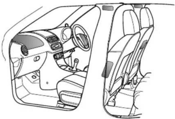
natural_image
Interior view of a car dashboard and steering wheel (no text or symbols visible)The SRSsystemincorporatesfrontandsideairbagsand sideheadimpactprotectionairbagsforboththedriverand frontseatpassenger.
Thefrontairbagsarelocatedinthecentrepadofthe steeringwheelandinthefasciapanelabovetheglovebox.
Sideairbagsarepositionedinthebackrestpaddingonthe outwardsideofbothfrontseats.
Sideheadimpactprotectionairbagsaresituatedbehindthe headliningabovethedoors.
Note: The frontairbags are not designed to operate as a result of rear collision, minor frontal or side impacts, or if the vehicle overturns; nor will it operate as a result of heavy braking.
Note: Inflation and deflation of the front air bag stakes place very quickly and will not protect against the effect of secondary impact that may occur.
Provided the front seat occupants are correctly seated and with seat belts properly worn, the air bags will provide additional protection to the chest and facial areas in the event of the car receiving a severe frontal impact.
SEATS&RESTRAINTS
Sideairbagsandsideheadimpactprotectionairbagsare designedtoofferadditionalprotectiontothesideofthe bodyfacingtheimpact,ifaseveresidecollisionoccurs.
IMPORTANT
•Evenifthevehicleisequippedwithairbags,you shouldalwayswearseatbeltstoreducetheriskof severecasualtyintheeventofacollision.Wearing seatbeltshelpsreducethepossibilityofhittingor beingpushedawayfrom,anyobjectintheinterior ofthecar.Theairbagsaresupplementaryprotection toseatbelts.Theyareanaidto,NOTreplacement of,seatbelts.
•Theairbagstogetherwiththelapand3-pointseat beltsprovideoptimumprotectionforadults,butnot forchildren.Childrenshouldbeprotectedbychild restraints.
AirbagDeployment

Tominimisetheriskofaccidentalinjury frominflatingairbags,seatbeltsshouldbe worncorrectlyatalltimes.Inaddition,both driverandfrontseatpassengersshouldadjust theirseattoprovidesufficientdistancefrom thefrontairbags.Ifsideairbags/sidehead impactprotectionairbagsarefitted,both driverandfrontseatpassengersshouldbe seatedtomaintainsufficientdistancefrom theupperpartofthebodytothesides ofthevehiclehiswillensuremaximum protectionwhenthesideairbags/sidehead impactprotectionairbagsaredeployed.
SEATS&RESTRAINTS
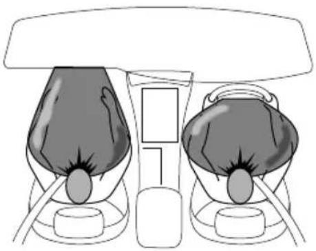
natural_image
Diagram of two identical mechanical components with no visible text or symbolsIntheeventofacollision, theairbagcontrolunitmonitors therateofdecelerationoraccelerationinducedbythe collision,todeterminewhethertheairbagsshouldbe deployed.
Operationoftheairbagisnotdependentonthespeed ofthecar,butonthetypeandsizeofobjecthit,angle ofimpactandtherateatwhichthecarchangesspeedas aresultofacollision.Deploymentoftheairbagisnot dependantontheamountofdamagetothevehicle.
Inthecaseofaseverefrontalcollision, bothfrontairbags will bedeployed. Inthecaseofaseveresidecollision, only thesideairbagandsideheadimpactprotectionairbagon theimpactsideofthevehiclewillinflate.
However,theremayalsobeimpactconditionswhereby onesetofsideandbothfrontairbagsdeployatthesame time,orwherefrontandsideairbagsrespondseparately asaresultofasecondaryimpactoccurringaftertheinitial collisionhastakenplace.
Airbaginflationisvirtuallyinstantaneousandoccurswith considerableforce,accompaniedbyaloudnoise.The inflatedbag,togetherwiththeseatbeltrestraintsystem, limitthemovementofafrontseatoccupant,thereby reducingtheriskofinjurytotheheadanduppertorso.
Note: When an airbag inflates, a fine powder is released. This is not an indication of malfunction, however, the powder may cause irritation to the skin and should be thoroughly flushed from the eyes and any cuts or abrasions of the skin after inflation, air bags deflate immediately. This provides a gradual cushioning effect for the occupant and also ensures that the driver's forward vision is not obscured.
SEATS&RESTRAINTS
IMPORTANT
- Obstructionsbetweenanairbagandtheoccupant mayaffectthecorrectdeploymentoftheairbag. Obstructionsmustnotinterferewiththeairbag inflationpassages.Accessoriesmustnotbeattached toorobscureanairbag.
- Frontseatpassengersshouldnotplacefeet,knees oranyotherpartofthebodyincontactwith,orin closeproximityto,afrontairbag.
• Aninflatingairbagcancausefacialabrasions and otherinjuriesiftheoccupantistooclosetothe airbagatthetimeofitsdeployment.
FrontSeatSideAirbags

Ensuresufficientdistanceexistsbetween thedriverandfrontpassengers'torsosand thesideofthevehicletoensurecorrect deploymentofthefrontsideairbags.
Frontseatsideairbagsaredesignedtoprotecttheheadand chestandwillbedeployedintheeventofthecarreceiving aseveresideimpact.Itwillnotbedeployedintheevent ofafrontorrearimpact.
Intheeventofasevereimpactononesideofthevehicle, theseatsideairbagwillbedeployedfromthesideofthe seat,onthatsideofthevehicle,topprovideacushionofair toprotectthefrontseatoccupant.Theseatsideairbagon theothersideofthevehiclewillnotbedeployed.
Seatswithsideairbagscanbeidentifiedbyan'Airbag' markingonthesideoftheseatbackrest.
Note: The manufacture and material of these is important to ensure correct operation of these at side air bag. Donot fit seat covers unless they are
approvedbythemanufacturer.ContactyourMG AuthorisedRepairertorepairorreplacefrontseats.
SideHeadImpactProtectionAirbags

Ensuresufficientdistanceexistsbetween thedriverandfrontpassengers'torsos andthesideofthevehicletoensure correctdeploymentofthesideheadimpact protectionairbags.
Sideheadimpactprotectionairbagsaredesignedtoprotect theheadandneckandwillbedeployedintheeventofthe carreceivingaseveresideimpact.Itwillnotbedeployed intheeventofafrontorrrearimpact.
Intheeventofasevereimpactononesideofthevehicle, thesideheadimpactprotectionairbagswillbedeployed fromtheroof,onthatsideofthevehicle,topprovidea cushionofairtoprotectthefrontseatoccupant. Theside headimpactprotectionairbagsontheothersideofthe vehiclewillnotbedeployed.
AirbagWarningLight

DONOTservice,repair,replace,modifyor tamperwithanypartoftheairbag,orwiring inthevicinityofanairbagcomponent;this couldcausethesystemtoactivate,resulting inpersonalinjury.
Awarninglight, mountedontheinstrumentpack, will alertyoutoanymalfunctionoftheairbags/pretensioners. Thelightwillilluminateasasystemcheckwhenthe ignitionisswitchedtoposition2andwillextinguishafter approximately6seconds.
Ifanyofthefollowingsymptomsoccur, thesystemshould beinspectedbyyourMGAuthorisedRepairer.
The warning light fail to illuminate when the ignition switch in position 2.
Twrnligbingsinguivithin
approximately six seconds after the ignition switch is in position 2.
The warning light illuminates while the car is being driven.
SEATS&RESTRAINTS
DisablingthePassengerAirbag \*

The Passenger Airbag should only be disabled when are ar facing child seatisfitted to the front passenger seat.

Whenanadultisseatedinthefront passengerseat,ensurethattheairbagis switchedon.
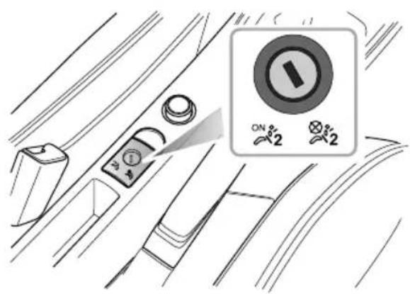
Wherefittedtheairbagdisableswitchislocatedinthe centreconsole.Todisablethepassengerairbag,insertthe keybladeintotheswitch.
Whentheswitchisturnedtothisposition,it atthepassengerairbaghasbeendisabled.
Whentheswitchisturnedtothisposition,it atthepassengerairbagisenabled.
PassengerAirbagOffWarningLight \*
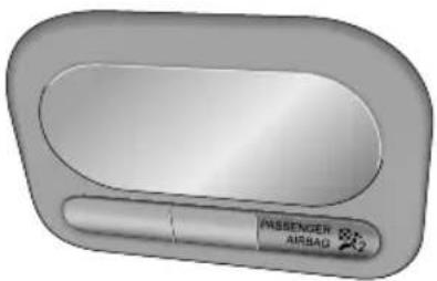
natural_image
3D rendered image of a passenger airbag with a handle and lid (no text or symbols visible)The warninglightislocatedintheinteriorlightassembly. If the passenger airbaghasbeendisabled, the lightwill illuminate until the airbagisenabled, Oncethepassenger airbaghasbeenenabled, the lightwillextinguish.
SpecialNotice

DONOTfitormodifyanairbag.Any changestothevehiclestructureorairbag systemwiringharnessarestrictlyprohibited.
AlwayscontactyourMGAuthorisedRepairerif:
•anairbagwhichinflatesinanaccidentneedsrepairand maintenance.
•anypartofanairbagmodulecovershowsignsof deteriorationordamage,theremaybeapotential safetyhazard.
IMPORTANT
Theemovabreplacementofairbagnodule mustbecarriedoutbyanMGAuthorisedRepairer.
After Year from initial date of registration (or installation date of fareplacement air bag), some components will need to be replaced by an MG Authorised Repairer. The appropriate page of the Warranty and Maintenance Manual must be designed and stamped on each homework has been completed.
SEATS&RESTRAINTS
DisposingoftheVehicle
Whensellingyourvehicle,youmustmakesurethatthe newownerknowsthatthevehicleisequippedwithairbags, andthedateoftheairbagsystemreplacement.
Uninflatedairbagsarepotentiallyverydangerousandmust besafelydeployedinacontrolledenvironmentbyqualified personnel,beforevehicleisscrapped.
ChildRestraints

Childrenmustbesecuredinthevehicleina childrestraintsystemappropriateforweight andsize.

DONOTputthechildonthelaporinarms whensittinginanyseat.


TheISOFIXanchoragesintherearseatare designedforusewithISOFIXsystemsonly.

Wheninstallingandusinganychildrestraint system,alwaysfollowthemanufacturer's instructions.

NEVERusearearwardfacingchildrestraint onaseatprotectedbyanACTIVEAIRBAG infrontofit,DEA THorSERIOUSINJURYto theCHILDcanoccur.

Failuretofollowtheadadvicecouldresultin seriousinjuryorevendeathofthechild.
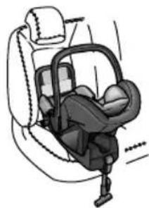
natural_image
Illustration of a car seatbelt with adjustable seat and seatbelt (no text or symbols)ChildRestraintInstructions
It is recommended that children below the age of 12 years old should be seated on there are seat of the vehicle, in a child restraint system appropriate to the children's weight and size.
It is recommended that a child restraint system that complies with UNECER44 standard are fitted in this vehicle. Checkmarkings on the child restraint system.
SEATS&RESTRAINTS
Childrenaremorevulnerablethanadultstoaninflating airbag.Itisrecommendedthatchildrenbelowtheageof 12yearsoldareseatedintherearseats.
Infantslessthan2yearsoldshouldberestrainedinaninfant childrestraintsystem.
Thereareanumberofchildrestraintsystemsavailableof differenttypeandspecification.Foroptimumprotection, itisrecommendedthatyouchooserestraintsystems appropriatetothechild'sageandweight.
It is important to comply with installation instructions supplied by the child restraint manufacturer and that child restraints system is properly secured to the vehicle. Failure to follow these instructions may cause death or serious injury to the child in an event of sudden stop or accident.
Note: Useanappropriatechildrestraintsystem until the child becomes large enough to be properly restrained by the vehicle's seat belts.
Note: DONOTinstallarearfacingchildrestraint systeminthefrontpassengerseat, unlessthefront passengerairbaghasbeendeactivatedorwhenan
airbagmanualdeactivationswitchisnotfittedtothe vehicle.
Note: Frontpassengerseatmustbepositionedfully rearwardsforinstallationofrearfacingchildrestraint systems.
Notre facirghidstrainsystem installationsintherearseatmayrequireforward adjustmentofthefrontseat.
Note: Seatheadrestraintsmayneedtobeadjustedor removedforinstallationofsomeforwardfacingchild restraintsystems.
Note: Rearparcelshelfmayneedtobetemporarily detachedtoenable Toptetheraccesstotheanchorage intherearoftheseatback.
IMPORTANT
- It is recommended that a child restraint system that complies with UNECER44 standard disfitted in this vehicle. Checkmarkings on the child restraint system.
- It is recommended that children should always be seated in therear of the vehicle in a child restraint system. If it is necessary for a child to travel in the front, it is essential that these are fully rearwards and upright seat back and the child dissecured in FORWARD FACING children restraint system.
- Rememberthatintheeventofacollisionorheavy brakingachildrestraintsystemthatisnotcorrectly fittedcouldmoveandinjureotheroccupants.Make surethatachildrestraintsystemisproperlysecured evenifnochildiscurrentlyusingit.
SEATS&RESTRAINTS
ApprovedChildRestraintPositions(forNon-ISOFIXChildRestraints)

If vehicle is not equipped with passenger air bag disables switch, rearward facing child restraints MUST NOT be installed on the front passenger seat.
| WeightGroup | SeatingPositions | ||||
| FrontPassenger | RearOutboardRearCentre | ||||
| Without Passenger AirbagDisable Switch | WithPassenger AirbagDisable Switch | ||||
| Airbag ON | Airbag OFF | ||||
| 0(upto10kg) | XXUUX | ||||
| 0+(upto13kg) | XXUUX | ||||
| I(9to18kg) | XXUUX | ||||
| II(15to25kg) | UUUUX | ||||
| III(22to36kg) | UUUUX | ||||
| U=Suitablefor‘Universal’categoryrestraintsapprovedforuseinthismassgroup.X=Seatpositionnotsuitableforchildreninthismassgroup. | |||||
ApprovedChildRestraintPositions(forISOFIXChildrestraints)
| WeightGroupSizeClass | Fixture | ISOFIXPositions | |
| RearOutboard | |||
| Carrycot | F | ISO/L1 | X |
| GISO/L2 | X | ||
| 0(upto 10kg) | E | ISO/RI | IL |
| 0+(upto 13kg) | E | ISO/RI | IL |
| D | ISO/R2 | X | |
| CISO/R3 | X | ||
| I(9to 18kg) | D | ISO/R2 | X |
| CISO/R3 | X | ||
| B | ISO/F2 | IUF | |
| BI | ISO/F2X | IUF,IL | |
| AISO/F3 | IUF | ||
| II(15to25kg)N/AN/A | X |
SEATS&RESTRAINTS
| WeightGroupSizeClass | Fixture | ISOFIXPositions | |
| RearOutboard | |||
| III(22to36kg)N/AN/A | X | ||
| IUF=SuitableforISOFIXforward-facingchildrestraintsystemsofuniversalcategoryapprovedforuseinthismass group.IL=SuitableforparticularISOFIXchildrestraintsystems(CRS)givenintheattachedlist.TheseISOFIXCRSare thoseofthe'specificvehicle', 'restricted'or'semi-universal'categories.X=NoISOFIXchildrestraintsystemapprovedinthisweightclass.ISOFIXsizeclassandseatdeviceA–ISO/F3=Forward-facingchildrestraintsystemB–ISO/F2=Forward-facingchildrestraintsystemBI–ISO/F2X=Forward-facingchildrestraintsystemC–ISO/R3=Rear-facingchildrestraintsystemD–ISO/R2=Rear-facingchildrestraintsystemE–ISO/RI =Rear-facingchildrestraintsystemF–ISO/LI =LeftLateralFacingpositionCRS(carry-cot).G–ISO/LI =RightLateralFacingpositionCRS(carry-cot).Note:ForChildRestraintsofClassR,thefrontseatmayrequireforwardadjustmentforsomerearwardfacing childrestraintsysteminstallation. | |||
ListofApprovedChildRestraintsSystems
| WeightGroupSizeclassCRSname | FixtureType | Category | ||
| 0+(upto13kg) | E | BritaxBabySafePluswith supportseatframe | ISO/RI | RearFacing Semi-universal |
| I(9to18kg) | BI | BritaxDuoPluswith T opT ether | ISO/F2X | ForwardFacingUniversal |
ISOFIXChildRestraintSystemsFastenvehicle-approvedISOFIXchildrestraintsystemsto
themountingbrackets.
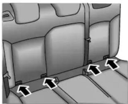
natural_image
Interior view of a car showing seat compartments and rear seats with directional arrows indicating movement (no text or symbols)When using ISOFIX mounting brackets for seat mounting, universally approved child restraints systems for ISOFIX may be used.
T op-tetherChildRestraintSystems

Childrestraintanchoragesaredesigned withstandnlyhosloadimposedy correctfittedhildestrainundero circumstancesaretheytobeusedforadult seatbeltharnessesorfoattachingother itemsorequipmenttothevehicle.
SEATS&RESTRAINTS
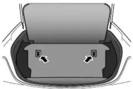
natural_image
Top-down view of a car's front compartment showing two internal compartments with directional arrows indicating movement or force (no text or symbols)- FastentheT op-tetherofthechildrestraintsystem totheanchorattherearoftherearpassengerseat backrest.
Note: When using seat mounting, universally approved childrestraintsystems, Top-tethermustbeused.
Note: Pleaserefertothechildrestraintsystem manufacturer'sinstructionsfordetails.
Starting&Driving
112Key
115 Child-ProofLocks
116AlarmSystem
121 StartingandDriving
I 25EconomicalandEnvironmentalDriving
128 CatalyticConverter
130FuelSystem
133ManualTransmission
134 BrakeSystem
139 Stability Control System (SCS) and Traction Control (TC)
141 Stop/StartIntelligentFuelSaving System
145 CruiseControlSystem *
147ParkingAid-PDC(ParkingDistance Control) *
149 TyrePressureMonitoringSystem (TPMS)
151LoadCarrying
STARTING&DRIVING
Key
Introduction

Pleasekeepthesparekeyinasafeplace-notinthecar!

Itisrecommendedthatsparekeysarenot keptonthesamekeyring, sincethismay causeinterferenceandpreventcorrectkey recognitionandthereforepreventtheengine fromstarting.

Theremotekeycontainsdelicateelectronic componentsandmustbeprotectedfrom impactandwaterdamage,hightemperature andhumidity,directsunlightandtheeffects ofsolvents,waxesandabrasivecleaners.
Differentkeykitsareprovidedaccordingtocar configurations.Onekitincludesaremotekeyanda mechanicalkey;andtheotherkitincludestwomechanical keys.Theycanopenalllocks.
Thekeyssuppliedwithyourcarareprogrammedto yoursecuritysystem.lfakeyhasnotbeenprogrammed accordingtoyourcar, it cannot start the engine.
Theremotekeyonlyworkwithincertainrangeltswork scopeisometimesinfluencedbythekeybatterycondition, physicalandgeographicalfactors.Forsafetyconsideration, afteryoulockyourcarbytheremotekey,pleaserecheck ifthecarislocked.
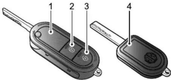
Relmotekey
2 Lockbutton
3 Unlockbutton
4 Mechanicalkey
STARTING&DRIVING
Ifyourkeyislost/stolenorbroken,areplacementcan onlybeobtainedfromanMGAuthorisedRepairer.The lost/stolenkeycanbedeactivated.Ifthelostkeyisfound, MGAuthorisedRepairerscanreactivateit.
Note: ReplacementkeysareonlyavailableviaMG AuthorisedRepairer.
Note: Thenewkeycannotbeofferedtoyou immediatelybecauseitneedssometimetomatchthe newkeywiththevehiclebyMGAuthorisedRepairer.
RemoteKeyBatteryRemovingandRefitting
If the battery needs replacing, the engine immobilisation warning light in the instrument pack flashes whenever the remote key is operated (seewarning lights and indicators in Instruments and Controls chapter).
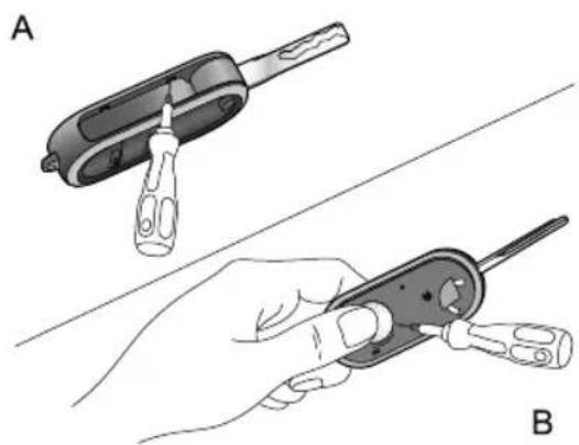
natural_image
Illustration of two hand tools: a handheld tool and a wiredriver, both with no visible text or symbols.I Unfoldtheremotekey.
2Useasmallflatscrewdrivertopriseoutthecapfrom thewholesithekegroove (A).
3Removewaterproofgasket.
4Pressthebatteryandslide,Insertasmallflat screwdrivertothegaptoremovethebattery.Pay attention@thepolarityofthebattery ( B ) .
STARTING&DRIVING
Note: Fingermarkswilladverselyaffectbattery life; if possible, avoid touchingtheflatsurfacesof thebatterywhenreplacingthenewone.
5Fitthenewbattery, ensuring that correct polarity is maintained. Meanwhile, align the waterproof gasket to themounting holes, makes sure that it is fitted correctly.
Note: It is recommended that you fit a CR2032 replacement battery.
6Refitcapinremotekey.
IMPORTANT
- Useofinappropriatebatterymaydamagethekey. Thenewreplacement'sratedvoltage, sizesand specificationsmustbethesamewiththeoldone.
- Inappropriatefittingofthebatterymaydamagethe key.
- Disposaloftheusedbatterymustbestrictlyin accordancewithrelevantenvironmentalprotection acts.
STARTING&DRIVING
Child-ProofLocks

NEVERleavechildrenunsupervisedinthe car.
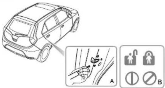
With the child-proof locks engaged, there are doors cannot be opened from insidethe car, but can be opened from outside the car.
LockorUnlocktheChild-proofLocks
- Opentherelevantreardoor, insertasmallscrewdriver intothechildlockslot(A).
•Turntheslottotherequiredposition(B). Note: Turnclockwiseforleftreardoor,andturn anti-clockwiseforrightreardoortoenable. Turnback totheverticalpositiontodisable.
STARTING&DRIVING
AlarmSystem
If the key is not recognised by the engine immobilisation system, the engine will be disabled.
LockingandUnlocking RemoteKey \*
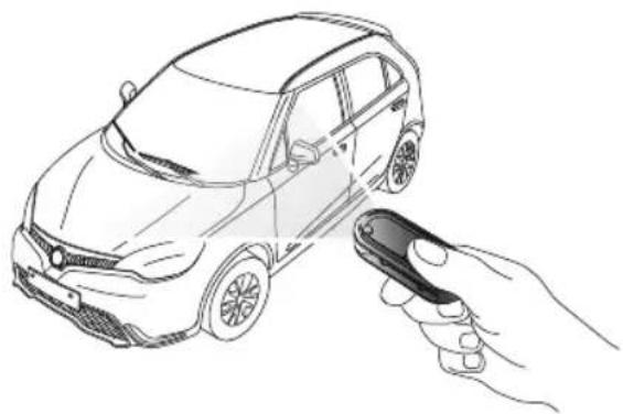
natural_image
Line drawing of a car being held by a handheld device (no text or symbols)Theremotekeymustbewithinrangewhenthebuttons arepressed.
Theoperatingrangemayvarydependinguponremotekey batteryconditionandmaysometimesbelimitedbyphysical andgeographicalfactors.
STARTING&DRIVING
Locking
UsingtheRemoteKey
I Closethedoorsandtailgate.
2Pressthelocbuttononce. Thedirectionindicator lightsflashthreetimestoconfirmthatthecaris securelylockedandthelockstatusalarmindicator lightstartstoflash.
UsingtheMechanicalKey
I Insertthemechanicalkeyintothedriver'sdoorlock andturnclockwisetolockalldoors.
2 Thedirectionindicatorlightsflashthreetimesto confirmthatthecarissecurelylockedandthelock statusindicatorlightstartstoflash.
Mislock
Ifthedriver'sdoorisnotfullyclosedwhentheremotekey lockbuttonispressedorthemechanicalkeyisusedfor locking,noneofthedoorswillbelocked,andanaudible alarmwillsound.
Ifthedriver'sdoorisclosedbutapassengerdooror tailgateisnotfullyclosedwhentheremotekeylockbutton ispressedorthemechanicalkeyisusedforlocking,all closeddoorswillbelocked,theopendoorortailgate willnotbelocked,thelockstatusindicatorlightwillnot illuminate,andanaudiblealarmwillsound.
Oncetheopendoorortailgateisclosed,thesystemwill enterlockingstatus,andthelockstatusindicatorlightwill illuminate.
STARTING&DRIVING
LockStatusIndicator
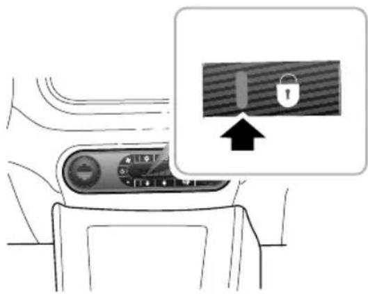
natural_image
Interior view of a car seat with a lock and directional icon (no text or symbols)The indicator is used to indicate the lock status. When the remote key or mechanical key lock sthedoor, the indicator will flash quickly for 10 seconds and then slow. The indicator extinguishes after ther remote key or mechanical key unlock sthedoor. If a mislock occurs, the indicator will not illuminate. When the interior lock switch locks the door, the indicator willilluminate. If the driver's door
isclosedfullybutanyotherdoorortailgateisnotclosed whentheinteriorlockswitchlocksthedoor,theindicator willflash.
Unlocking
UsingtheRemoteKey
Presstheunlockbuttononcetounlockalldoors.The directionindicatorsflashonce.
UsingtheMechanicalKey
I Insertthemechanicalkeyintothedriver'sdoorlock andturncounterclockwiseoncetounlockalldoors.
2 Thedirectionindicatorsflashonce.
Note: If the vehicle is unlocked but a door is not opened within 30 seconds, the vehicle will automatically relock.
InteriorLockSwitch
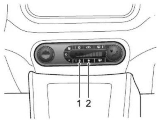
InteriorLockLockingSwitch
2InteriorLockUnlockingSwitch
Presstheinteriorlocklockingswitchtolockalldoors. Whendoorsarelockedhelockstatusindicatorwill illuminate.
STARTING&DRIVING
If the driver's door is not closed, the interior lockings switch will not function.
Ifanyotherdoorortailgateisnotclosedwhentheinterior lockingswitchispressed,thelockstatusindicatorwillflash, indicatingamislock.Theopendoorortailgatewillnotbe protectedwhentheopendoorortailgateisclosed,the systemwillentertheprotectedstatus.
Presstheinteriorlockunlockingswitchtounlockalldoors, andthelockstatusindicatorwillextinguish.
Note: If the doors are locked with theremote key, the interior lock switch will not function.
InteriorDoorHandles
If the door have been locked by the interior lock switch or Speed Related Locking.
Usethedoorhandlestoopenthedoor:
I Firstoperationofthedoorhandleunlocksthedoor.
2Secondoperationofthedoorhandleopensthedoor.
Note: If the car is locked using the key or remote key the doors will be 'super-locked'. Whilst in this locked condition the door handles a rerendered in operative.
SpeedRelatedLocking
Thisfeaturelocksallthedoorsautomaticallywhenthe roadspeedexceeds3MPH(5km/h).Automaticallyallthe doorsareunlockedaftertheremotekeyisremovedfrom theignition.
STARTING&DRIVING
StartingandDriving
DockingStation

DONOTremoveortouchthekeywhilethe carisinmotion.
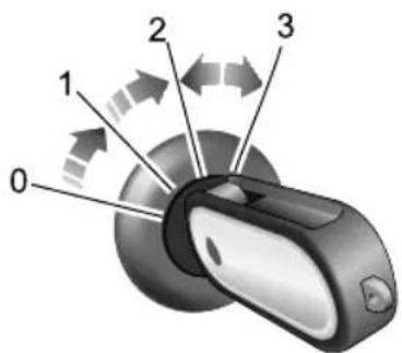
Theignitionswitchislocatedontherightsideofthe steeringcolumn,andusesthefollowingsequencetoinitiate theignitionandstarttheengine.
Position0(LOCK)
•Thekeycanbeinsertedorremoved.
•T oachievetheeeringlock,whenkeyremoved.
Position / (ACC)
• Turnofftheignition, thekeycannotberemoved.
• Someelectricalequipment can be operated, such as wipers, electric windows, mirrors.
Position // (∅N)
- Allinstruments, warninglights and electrical circuits are operational.
Position /// (START)
- Starttheengine.
-Releasethekeyimmediatelywhenenginestarts,the ignitionwillreturntopositionllautomatically.
Note: Whenthekeyisintheignition, if the driver's door is opened, an audible warningsound to indicate that the key is not removed.
Note: Before starting the engine ensure that the gear lever is in the neutral position and the clutch pedal is pressed.
Note: If the steering wheel is locked and the key can not be turned from position 0 to position /turn the
STARTING&DRIVING
steeringwheelleftandrightwhileturningthekeyto unlockthesteeringwheel.
StartingtheEngine

NEVERstartorleavetheengine running in anunventilated building-exhaust gases are poisonous and contain carbon monoxide, which can cause unconsciousness and may even be fatal.

CatalyticConvertercanbedamagedifthe wrongfuelisused,orifanenginemisfire occurs.Beforestartingtheengine,you shouldbeawareoftheprecautionsdetailed underthesection'CatalyticConverter'.
StartingtheEngine
I Switchoffallunnecessaryelectricalequipment (includingtheairconditioning);
2Applytheparkingbrake;
3 Ensure that the gear lever is in the neutral position then pressthe clutchpedaltothefloor;
4Insertthekeyandturntheignitionclockwiseto positionllltostarttheengine.Releasethekeyas
soonastheenginehasstarted,theignitionwillreturn topositionllautomatically.
Note:Continueduseofthestarterwillnotonly dischargethebattery,butmaydamagethestarter motor,starterringgearorcatalyticconverter.
Donotpresstheacceleratorpedalwhenstarting,donot operatethestarterformorethan 15secondsatatime. Iftheenginedoesnotstart,turnofftheignitionswitch andwaitatleast 10secondsbeforerepeatingthestart procedure.
If the key is not recognised by the engine immobilisation system when the key is inserted into the ignition, the engine will be disabled. A warning icon will be illuminated (see warning lights and indicators in Instruments and Controls chapter).
IMPORTANT
Dodeaveignitionswitchpositiondr positionllwhentheengineisnotrunning,otherwise itmayleadstobatterydischarge.
•Engineimmobilisationisavailableforthevehicle.
- Whentheengineisrunning, donotturntheignition switchtopositionIII, thisoperationmaydamagethe startermotor.
ColdClimates
Intemperatures of -10°C cand below, engine cranking times will increase. Its essential that all unnecessary electrical equipment is switched off while cranking.
StoppingtheEngine
Afterbringingthecartostop, ALWAYSapplythe parkingbrake;
Apply the parking brake;
Bnsurethatthegearleverisintheneutralposition;
STARTING&DRIVING
4TurnthekeytoPosition0,removethekeyfromthe switch.
Note: After strenuoustowing or driving at high speed (particularly in hot weather), it suggested to allow the engine to die for a few minutes before switching off, which enable the cooling system to work continuously to lower the engine temperature.
EconomicalandEnvironmentalDriving
Running-in
Theengine, transmission, brakesandtyresneedtimeto 'bed-in' and adjust to the demand so every day motoring. During the first 900 miles (1,500 km), it is essential that you drivewith consideration for the running-in process and heed the following advice:
- Donotallowtheenginetoexceed3000rpmminanygear orthevehiclespeedtoexceed72MPH(120km/h).
- Donotoperateatfullthrottleorallowtheengineto labourinanygear.
- Donotdriveataconstantspeed(eitherhighspeedor lowspeed).
- Avoidheavybrakingwherepossible. After900miles(1,500km),enginespeedscanbegradually increased.
EnvironmentProtection
Yourcarhasbeendesignedwiththelatesttechnologyin ordertominimisetheenvironmentalimpactofexhaust emissions.
DrivingStyle
Thewayinwhichyoudriveyourcarhasasignificant bearingonenvironmentalpollution,aswellasaffectingthe amountoffuelyouuse.
Avoidfullthrottleacceleration
Steady, rather than rapid, acceleration uses considerably less fuel, reduces exhaust pollutants and minimises the weartomechanical components.
Avoiddrivingatmaximumspeed
Fuelconsumption, exhaustemissions and noise levels all increases significantly at high speeds.
Donotdriveinalowgearforlongerthan
necessary
Drivinginlowergearsusesmorefuelandcreatesmore noisChangeuptoahighergearassoonaspossible, provideditdoesNOTcausetheenginetolabour.
STARTING&DRIVING
Drivesmoothly
Anticipatingobstructionsandslowingdownwellin advance,avoidstheneedforunnecessaryaccelerationand harshbraking.Asmoothdrivingstylenotonlyreduces fuelconsumption,butcanreducetheemissionofnoxious gases.
Drivinginrain

Emergencybraking, accelerating and steering onslipperyroadswillreducethevehicle's handlingperformanceandgrip.
When raining the windows may fog, reducing visibility (Use the Air-conditioning demist function).
Gripwillbereduced, sopleasedrivecarefully.
Reducespeedwhenitrains.
Avoidaquaplaning(theeffectofafilmofwaterbetween thetyresandtheroad)affectingsteeringandbraking performance.
Avoiddrivingthroughfloodsafterheavyrain,whichmay leadtoseriousdamagetothevehicle.
Howtosavefuelandextendthelifeofthe vehicle
The following a resomes suggestions on saving fuel and extending the life of the vehicles.
- Maintain the correctty repressure; insufficient air pressure will accelerate tetryrewear and wasteful.
Doctorunnecessaryeigheadvaps willincreasetheengineloadresultinginhigherfuel consumption.
Avoidengineidlingforextendedperiods.
- Maintainslowandsmoothaccelerationandavoidharsh accelerationchangehighergearassoompossible.
- Avoidlabouringtheengineoroverrunningchoose appropriategearsaccordingtotheroadconditions.
- Avoidcontinuousaccelerationdeceleration. stop-godrivingstylewillconsumemorefuel.
Avoidnecessarystoppingdrakingaintain steadyspeedandattempttoanticipatetrafficlights. Keepanappropriatedistancefromothervehiclesto avoidemergencebrakingandreducebrakepadwear.
Avoid traffic congestion area such as possible.
- Donotridethebrakepedal, this can cause premature wear, overheating and increased fuel consumption.
- Maintainanappropriatespeedonthehighway.Higher speedsusemorefuel.Appropriatespeedcansavefuel.
- Maintainthecorrectwheelalignment.Avoidcollision withthekerbandreducespeedonun-maderoads.Out ofspecificationwheelalignmentnotonlywillleadto excessivetyrewear,butalsoincreasestheengineload andfuelconsumption.
- Avoiddrivingonmudorbeaches. This will prevent corrosion of the vehicle underside.
- Maintain the vehicle in accordance with MG recommendations. Dirty air filters, oil etc., will reduce the engine's performance and raise fuel consumption. To extend the life of all components and reduce operating costs, regular MGA approved maintenance is needed.
- Donotstoptheenginestraightafterhighspeedorlong ascentsortowingatrailer.Allowtheenginetoidlefor 20to100secondsdependingupondrivingloadsand conditions.Avoidhardaccelerationonacoldengine.
Maintenance
Havethevehicleregularlyserviced
Regularly servicing will ensure optimum fuel consumption and minimise exhaust, pollutant effectively extending the service life of the car.
Checktyrepressuresregularly
Under-inflatedtyresincreasetherollingresistanceofthe carwhich,inturn,increasesfuelconsumption.Overor under-inflatedtyreswearoutmorerapidlyandalsohavea detrimentaleffectonthecar'shandlingcharacteristics.
Donotcarryunnecessaryloads
The additional weight of unnecessary load swastes fuel, especially top/sta condition whether frequently required to set off from stationary.
STARTING&DRIVING
CatalyticConverter

Exhausttemperaturescanbeextremelyhigh, DONOTparkongroundwherecombustible materialssuchasdrygrassorleavescould comeintocontactwiththeexhaustsystem -indryweatherafirecouldresult.
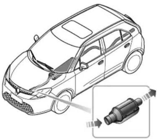
natural_image
Technical line drawing of a car with an inset showing internal components (no text or symbols)Theexhaustsystemincorporatesacatalyticconverter,this convertspoisonousexhaustemissionsfromtheengineinto lessharmfulgases.
Catalyticconvertersareeasilydamagedthroughimproper use,especiallyifthewrongfuelisused.
Pleaseobservethefollowingprecautionstominimisethe chanceofaccidentaldamage.
Fuel
•UseONLYfuelrecommendedforyourcar.
- Neverallowthecartorunoutoffuel-thiscouldcause amisfirewhichcoulddamagethecatalyst.
Starting
Whendriving,youshouldpayattentiontothefollowing points:
- Donotcontinuetooperatethestarterafterafewfailed attempts, seekMGAuthorisedRepairer.
- Donotoperatethestarterifanenginemisfireis suspectedanddonotattempttoclearamisfireby pressingtheacceleratorpedal.
- Donotattempttopushortowstartthecar.
Driving
Whendriving,youshouldpayattentiontothefollowing points:
- Donotoverloadorexcessively'rev'theengine.
- Donotstoptheenginewhenthecarisinmotionwith agearselected.
- SeekMGAuthorisedRepairerifyouthinkyourcaroil consumptionisabnormal.
•lfamisfireissuspected,orthecarlackspowerwhile driving,providedtheenginehasreacheditsnormal operatingtemperature,itmaybedrivenSLOWLY(at riskofcatalystdamage)toanMGAuthorisedRepairer orsuitablyequippedservicinggarage. - Donotdriveonterrainlikelytosubjecttheunderside ofthecartoheavyimpacts.
Note: Anyenginemisfire, lossofengineperformance orenginerun-on, could seriously damagethecatalytic converter. Regularmaintenancemustbecarried outinaccordance with the schedules specified in the 'Warranty and Maintenance Manual'.
STARTING&DRIVING
FuelSystem
FuelRequirements

Useonlytherecommendedfuelwhichmeets nationalstandard!Seriousdamagetothe catalyticconverterwilloccurifthewrong fuelisused.
Pleaseusethefuelwhichisrecommendedandcertified bythemanufacturer.See'MajorParametersofEngine'in 'TechnicalData'.
SafetyontheForecourt

Vehiclefuelgasesarehighlyflammable and,inconfinedspaces,arealsoextremely explosive.
Alwaystakecarewhenrefueling:
- Switchofftheengine.
• Donotsmokeoruseanakedflame. - Donotuseamobilephone.
- Avoidspillingfuel.
- Donotoverfillthetank.
STARTING&DRIVING
FuelFiller
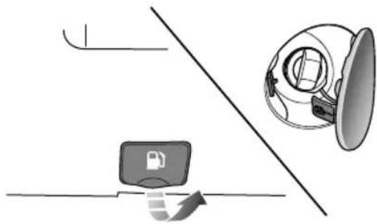
natural_image
Illustration of a computer monitor with a lock icon and a megaphone, connected by a diagonal line (no text or symbols)FuelFillerFlap
Thefuelfillerflapislocatedontherearright-handwing. Pullthefuelfillerflapreleaseleverunderthedriverside instrumentpacktoopentheflap.
FuelFillerCap
Unscrewthefillercapanti-clockwiseandallowany pressureinsidethetanktoescape,beforeeremovingthe cap.
Afterrefuelling,tightenthefillercapclockwisetillhearing 3"click"sounds.
FuelFilling

DONOTfullyfillthetankifthevehicleisto beparkedindirectsunlight,orhighambient temperature-expansionofthefuelcould causespillage.
Asmallcoverflapisincorporatedintothefillerneck. Insertingthecorrectnozzleintothefillerneckwillfully openthecoverflap.
Afterrefueling,iftheengine runsunevenly,switchoff and seekanMGAuthorised Repairer before attempting to restart the engine.
FuelCut-offSwitch

ALWAYScheckforfuelleaksbeforeresetting thefuelcut-offswitch.
STARTING&DRIVING
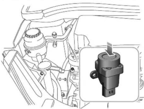
natural_image
Technical diagram of a mechanical component with an inset view showing a disassembled component (no text or labels present)Intheeventofacollisionorsuddenimpact,thefuelcut-off inertiaswitchautomaticallyisolatesthefuelsupplytothe engine,unlocksthedoors,flashestehazardlightsand turnstheinteriorlightson.
Thefuelcut-offInertiaswitchislocatedontherighthand ofinnerwingintheenginecompartment.
Theswitchmustberesetbeforetheenginecanbestarted. Resettheswitchbypassingthetopoftheswitch(arrowed inillustration).
STARTING&DRIVING
ManualT transmission
GearLever
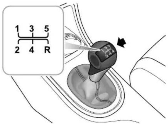
Themanualtransmissionisa5-speedtransmission, which includes6gears, ie. 1, 2, 3, 4, 5 and R (reversegear).
Synchronizersareprovidedonallforwardgears.
PrecautionsWhenDriving:
- Whenswitchingbetweentheforwardgearsandreverse gear,ensurethevehicleiscompletelystationary,wait foramomentandthenfullypresstheclutchpedalto completethegearshift.
- Donotrestyourhandonthegearleverwhiledriving-pressurefromyourhandmaycauseprematurewearto thegearselectormechanism.
- Donotrestyourfootontheclutchpedalwhendriving -excessiveweartotheclutchwillresult.
- Donotholdthecarstationaryonahillbyslippingthe clutch. Thiswillwearouttheclutch.
STARTING&DRIVING
BrakeSystem
FootBrake
Foradded safety, the hydraulic brakingsystem operates through dual circuits. If one circuit should fail, the other will continue to function, but greater pedal pressure will be needed, and increased brake pedal travel, and longer stopping distances will be experienced. In the event of abrake failure where only one circuit is operational, the car should be brought too a halt as soon as a traffic condition safely allow. DONOT continued driving-seek MGA authorised Repairer assistance.
ServoAssistance
Thebrakingsystemisservoassisted,alwaysbeawareof thefollowing:
- Neverallowthecartofreewheelwiththeengineturned off.
- Alwaystakeparticularcarewhenbeingtowedwiththe engineturnedoff.
If the engines should stop for any reason while driving, bring the cartoahaltas quickly a traffic condition safely allow,
anddonotpumpthebrakepedalasthebrakingsystemwill loseanyremainingservoassistance.
BrakePads

DONOTrestyourfootonthebrakepedal whiledriving;thismayoverheatthebrakes, reducetheirefficiencyandcauseexcessive wear.
Forthefirst900miles(1500km),youshouldavoid situationswhereheavybrakingisrequired.
Remember that regular servicing is vital to ensure that all the brake components are examined for wear at the correct intervals, and changed when required to ensure long terms safety and optimum performance.
WetConditions
Drivingthroughwaterorheavyrainmayadverselyaffect brakingefficiency. The SCS (StabilityControlSystem) includes a BrakeDiscWipingfunction which is activated whenthewindscreenwipersareused.
ElectronicBrakeForceDistribution(EBD)
YourcarisequippedwithElectronicBrakeForce Distribution(EBD),which,inordertomaintainbraking efficiency,distributesbrakingforcesbetweenfrontand rearwheels,underallloadconditions.EBDmonitoring systemislinkedtoparkingbrake/brakesystemlightonthe instrumentpack.
If this light illuminates, there is a fault with the braking system, and EBD may not be available. If this occurs, stop the car as soon as safety permits and seek MGA authorised Repairer assistance immediately. DONOT drivethe car with parking brake/brakesystem light illuminated.
ElectronicBrakeAssist(EBA)
YourcarisequippedwithElectronicBrakeAssist(EBA), which, reactstothespeedatwhichthebrakepedalis applied. If, inanemergencysituationthebrakesareapplied faster than the limits set within the system, then full ABS application is applied to bring the cartoastopin the shortest possible distance.
HillHoldControl
HillHoldControlisacomfortfunction.Itworkson inclineswhenthecardetectsithascometoa'standstill status'.Oncetheclutchpedalhasbeenpresseddown and thebrakepedalreleased,thevehiclewillmaintainpressure inthebrakingsystemfor 1–2seconds.Afterthis,theHill Holdwillrelease.
Anti-lockBrakes(ABS)

ABScannotovercomethephysical limitationsofstoppingthecarintooshort adistance,corneringattoohighaspeed,or thedangerofaquaplaning,i.e.wherealayer ofwaterpreventsadequatecontactbetween thetyresandtheroadsurface.
The fact that a car is fitted with ABS must never attempt the driver into taking risk that could affect this / hersafety orthatof other road users. In all cases, it remains the driver's responsibility to drivewith innormalsafety margins, having due consideration for prevailing weather and traffic conditions.
The purpose of the anti-lockbrakingsystem (ABS) is to prevent the wheels from locking while braking, thereby enabling the drivertoretainsteering control of the car.
Undernormalbrakingconditions, ABSwillnotbe activated. However, shouldthebrakingforceexceedthe availableadhesionbetweenthetyresandtheroadsurface causingthewheelstolock, thenABSwillautomatically
comeintooperation. This will berecognizable by a rapid pulsation felt through the brake pedal.
BrakinginanEmergency

DONOTpumpthebrakepedalatanytime; thiswillinterruptoperationoftheABSand mayincreasebrakingdistance.
Ifanemergencysituationoccurs, the drivers should apply full braking effort to even when the roads surface is slippery. ABS will ensure that the wheels donotlock and that the car is brought to a halt in the shortest distance for the prevailing roads surface conditions.
Note: Onsoftsurfacesuchaspowderysnow, sandor gravel, the brakingdistancerequiredbytheanti-lock brakingsystemmaybegreaterthanfornon-ABS brakingventhoughimprovedsteeringwouldbe experience thisisbecausethenaturalactionof lockedwheelsonsoftsurfacesistobuildupawedge of surfacematerialinfrontwhichassiststhecarto stop.
STARTING&DRIVING
Nomatterhowhardyoubrake,youshouldbeableto continuesteeringthevehicleasnormal.
ABSWarningLight
Seethewarninglight'ABS'in'InstrumentsandControls'.
Note: Thenormal(non-ABS)brakingsystemremains fullyoperationalandisnotaffectedbypartialor fulllossoftheABS. However, brakingdistancesmay increase.
ParkingBrake

DONOT drivewith the parking brake applied, or apply the parking brakewhile the carisin motion. This could result in loss of control, prevent the ABS from functioning correctly, and may even caused damage to therear brakes.
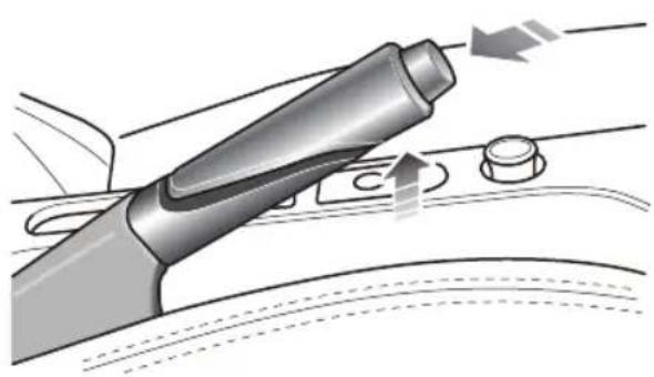
natural_image
Diagram of a mechanical component with directional arrows indicating motion or force (no text or symbols)STARTING&DRIVING
Theparkingbrakeoperatesontherearwheelsonly.T o applytheparkingbrake,pulltheleverup.Alwaysapplythe parkingbrakefullywheneveryouparkthecar.
T orelease,pulltheleverupslightly,pressthebutton (arrowedinillustration)andfullylowerthelever.
Whenparkingonasteepslope, donotrelyontheparking brakealonetoholdthecar.
STARTING&DRIVING
StabilityControlSystem(SCS) and T ractionControl(TC)
StabilityControlSystem(SCS)
SCSisdesignedtoassistthedriverincontrolofdriving direction.
WhenSCSdetectsthatthevehicleisnotmovinginthe intendeddirection,itwillintervenebyapplyingbrakeforce toselectedwheelsorthroughtheenginemanagement systemtopreventslidingandassistinbringingthecarback totherightdirection.
T ractionControl(TC)
The purpose of electronic traction control is to aid traction, thereby helping the driver to maintain a control of the carinsituations where one or both of the driving wheels are spinning (fore example, if onewheel is onice and the other on tarmac).
Thetractioncontrolsystemmonitorthedrivingspeedof eachwheelindividually.Ifspinisdetectedononewheel, thesystemautomaticallybrakesthatwheel,transferring torquetotheopposite,non-spinningwheel.Ifbothwheels
arespinning, thesystemwillreduceenginespeedinorder toregulatewheelrotationuntiltractionisregained.
Note: The individual wheel braking feature of the traction control system will operate at road speeds above 62 MPH (100 km/h). The engine torque reduction feature continues to function up to the car's maximum speed.
STARTING&DRIVING
SwitchingOnandOff
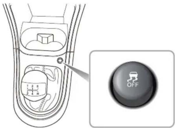
- BrieflypresstheSCSswitch(lessthan2seconds).TC isdisabled, 'TractionControlOff' warninglightwill illuminate.
- Press the SCS switch (more than 2 seconds). TC and SCS are both disabled. 'T raction Control Off warning light and Stability Control System Off warning light will illuminate.
NoPressingEC/SCisablewitcfor morthandcondwillconsidereds mis-operationBothsystemswillremaindisabled untiltheswitchispressedforasecondtimeorthe keyisremoved.
Brieflypress the SCSwitch(les than seconds) again, SCSandTCwillresumeandthewarninglightwill extinguish.
NotDisablingSCSandTCwillnotaffecthe operationofABS.AlwaysdisableTCwhendriving withsnowchainsfitted.
SCS/TCWarningLight
Foinformation: warninglightoperationefero 'WarningghasIndicatorInstruments and Controls'.
STARTING&DRIVING
Stop/StartIntelligentFuelSaving System
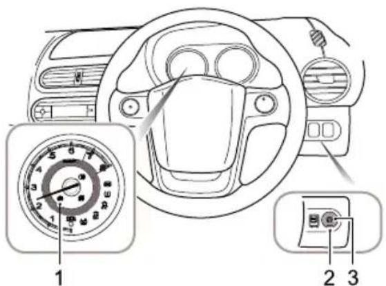
Instrumentindicator
2Switchindicator
3Mainswitch
EngineStop/Starthasbeenincorporatedintovehiclesin anefforttoreduceemissions.Asthenamesuggeststhe systemwillallowtheenginetobeswitchedoffwhenengine powerisnotrequiredandthenautomaticallyberestarted whenitis.Thissystemdefaults"on"atignitionon,the warninglightintheswitch(2)willilluminate,stopstartcan beturnedoffbypassingthemainswitch(3).Whenstop startisswitchedofftheindicatorintheswitchisoff.
Note: If driving through deep, or floodwater, disable the stop starts system by pressing these switch (3).
STARTING AND DRIVING
Automatic Shutdown of Engine
Although the engine will not be running when the vehicle stops and the stop start function cuts in, certain actions could render the vehicle dangerous:
I Driver exiting the vehicle whilst the seat belt is fastened
2 Leaving the ignition switched on when refuelling - ALWAYS remove the key.
Stop/Start Intelligent Fuel Saving will be initiated when the following conditions are met, at this time the indicator lamp in the IPK will illuminate:
- Manual transmission – neutral selected, clutch pedal released, and speed is below 3 mph. Note: Steering effort will increase until the conditions for engine restart occur.
- Vehicle speed prior to parking was in excess of 6 mph
• (10km/h). - Driver's door and bonnet are closed.
- Driver's seat belt is fastened.
Stop Start Intelligent Fuel Saving will be disabled under the following conditions:
• Engine temperature too low.
• Defrost selected in the AC system.
- Blower speed 3 or 4 selected on non A/C cars. Blower speed above 4 selected on A/C cars.
- Low battery power or battery not within the desired range.
• Insufficient brake vacuum.
- Starter motor operated more than 3 times a minute.
- Reverse gear selected or has been selected prior to stopping if the vehicle has not exceeded 6 mph (10km/h).
• High altitude areas.
Automatic Engine Start
The vehicle will automatically restart if the driver carries out the following, at this time the indicator light in the IPK will extinguish:
STARTING&DRIVING
- Manualtransmission-neutralselected,clutchor acceleratorpedalpressed.
Note: Insome individual casethe MIL may illuminate during automatic restart. This is caused by battery voltage reduction, not a fault. If the MIL stays on, seek advice from an MGA authorised Repairer.
Undercertainconditionsthevehiclemayautomatically restartwithoutdirectdriverinput(aslongasthestopstart operationcriteriaismet):
•Defrostofwindscreenisselected.
- Manualheaterblowerspeedselectionismovedabove speed3,ETCACblowerspeedselectionismoved abovespeed5.
- Batteryvoltagedropsbelowapredeterminedlimit. Vehiclemoves/rolls-vehiclespeedsignal.
•Vehiclemoves/rolls-vehiclespeedsignal.
- Brakevacuumdropsbelowapredeterminedlimit.
- Stop/Startmasterswitchispressed.
Note: When under automatic stopstart control, vehicles fitted with manual transmissions will require neutral to be selected to restart the engine.
If any of the following conditions occur after automatic stop start is initialised, the indicator lamp in the IPK extinguishes and the vehicle will require starting with the key.
- Driver'sseatbeltunfastened.
- Driver'sdoorisopened.
•Bonnetisopened.
If the vehicle is stalled when underautomatic stop start control and none of the above are present, the vehicle can be restarted by selecting neutral and pressing the clutch pedal.
Noffeattenpoltage automatic restartingafterstallingmaybeinhibited.
Battery

Whenchargingthebattery, startingthecar withanexternalpowersourcesupplying powerfromthevehicle, thenegativecable mustbeconnectedtoasuitablepositionon thevehiclebody. Failuretodothiswillresult ininaccuratebatterypowercalculation which affectomatStop/Start control.
STARTING&DRIVING

DONOTdisconnectthebatterysensorunless absolutelynecessary.removalwillresultin inaccuratebatterypowercalculationwhich willeffectautomaticStop/Startcontrol.
Note: Failuretooperatewithinthefollowing guidelineswilleffectbatteryperformance and automaticStop/Startcontrol:
I Afterpowerinterruptions(batterydisconnection) theautomaticStop/Startfunctionwill be suspendeduntilthevehicleisleftinalockedstate foratleast4hourswhilstthesystemrelearnsthe stateofthebattery.
2Ifthevehicleisruncontinuallyformorethan100 hoursuninterrupted,theStop/Startfunctionwill besuspendeduntilthevehicleisleftinalocked stateforatleast4hourswhilstthesystemrelearns thestateofthebattery.
If the battery requires replacement, ALWAYSuse agenuine part to the manufacturer specification. Failure to adhere this can affect the automatic Stop/Start system.
Stop/StartIntelligenRtUGlavingSystem Failure
IntheeventofaStop/StartIntelligentFuelSavingSystem failure,contactanMGAuthorisedRepairer.
Thistop/StahtelligerFuSavingsystemare effectedbyfaultswithinothervehiclesystems-inthe eventoffailurecontactanAuthorisedMGRepairer.
SeriousBatteryCapacilyoStarter Inoperative
In case ferious battery powd os automatic Stop/Start and keystart may not be possible. In this case referto the Emergency Information chapter, Emergency Starting section for further details.
STARTING&DRIVING
CruiseControlSystem \*
CruiseControlSystem
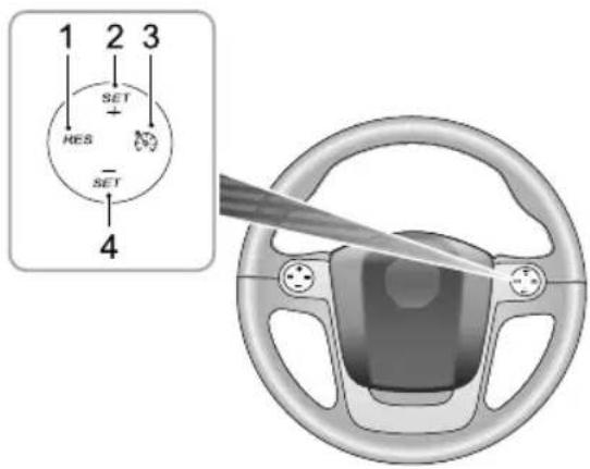
I Resetswitch
2Increasesetswitch
3Mainswitch
4Decreasesetswitch
Cruisecontrolenablethedrivertomaintainaconstant roadspeedwithoutusingtheacceleratorpedal. This isparticularlyusefulformotorwaycruising,orforany journeywhereaconstantspeedcanbemaintainedfora lengthhyperiod.
The following precautions must be observed when using cruise control:
• DONOTattempttousecruisecontrolwhenusing reversegear.
• DONOTusecruisecontrolonwindingorslipperyroad surfaces, intherain, orintrafficconditions wherea constantspeed cannot easily be maintained.
•ALWAYSswitchchoffthemasterswitchwhenyouno longerintendtousecruisecontrol.
CruiseControlSystemOperation
Thecruisecontrolsystemconsistsoffourswitches:the mainswitchresetwitchandwspeedincrease/decrease setwitchesAlswitchesaremountedtherightsidof thesteeringwheel.
Whether vehicle speed above 25 mph (40KM/h), pressdownthemasterswitch (3inthe
STARTING&DRIVING
figure), the indicator lamp in the instrument pack illuminates and the cruises system is activated.
2PressthespeedsetswitchSET+/SET-(2and4shown inthefigure),setthememomoryspeedofthecruise system,andthecruisesystemwilltakeeffect.Atthis time,thecruisecontrolsystemwillmaintaintheset speedwithoutdepressingtheacceleratorpedal.Cruise controlwillonlyoperatebetweenvehiclespeedsof25-125mph(40-200km/h).
Note: Thesetspeedheldinthecruisecontrolmemory will be cancelled when either the cruise control master switch is pressed or the ignition key removed.
Cruisecontrolwillbedisengagedwhenthebrakepedalis pressedoradifferentgearisselected.Toreturntoyour previoussetspeed,presstheRESswitch(figure 1).
Note: The cruise control system can only work when the gear lever is in 3rd gear or above.
ChangetheSetSpeed
Shortlypress(lessthan0.5seconds) theSET+/SET switch decrease/decrease vehicle speed
incrementmph/1km/the vehicle will accelerate/deceleratetothenewsetspeedressand holdset/SE switch vehicle keep accelerating/deceleratinguntiltheswitchisreleased. The selectedspeedissetaccordingly.
The vehicle can also be driven using the accelerator pedal with the cruise control activated. Once the accelerator pedal is released, the system will return to the sets speed.
When accelerating, presstheSET+switch, thesystemwill apply the higher vehicles speed asthenewsetspeed.
STARTING&DRIVING
ParkingAid-PDC(ParkingDistance Control) \*
ParkingAid(UltrasonicParkingRanging WarningDevices)

The purpose of the parking aid to assist the driver during reverting! Thesensors may not be able to detect certain types of obstruction, e.g. narrow posts or small objects nomore than a few inches wide, small objects close to the ground, objects above the level of the boot and some objects with nonreflective surfaces.

Keepthesensorsfreefromdirt,iceandsnow. Ifdepositsbuilduponthesurfaceofthe sensors,theirperformancemaybeimpaired. Whenwashingthecar,avoidaiminghigh pressurewaterjetsdirectlyatthesensors.

Itisimportanttorememberthatthesystem isnomorethananAIDtoparking.Itisnot foolproofinoperation,norisitasubstitute forobservationorpersonaljudgement.
Threeultrasonicsensors,situatedintherearbumper,scan anareabehindthecarsearchingforobstructions.Ifan obstructionisdetected,thesystemcalculatesitsdistance fromtherearofthecarandcommunicatesthisinformation tothedriverbysoundwarningchimes.
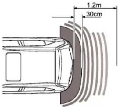
STARTING&DRIVING
Parkingaidoperation:
ThePDCsystemisenabledautomaticallywhentheignition isinposition2andreversegearisselected.Itisswitched offassoonasthegearselectionleverismovedfrom reverse.Ashortbeepisgivenbythesounderinthe instrumentpackwithinl secondafterselectingreverse geartoindicatethatthesystemisoperatingnormally.
Whilereversing, the instrument packsoundergives an audible warning forthed distance between the vehicle and an object:
- Ifanobstructionislocatedwithin1.2mrangeofthe rearparkingaidsensors,thewarningcommences.As thecarmovesclosertotheobstruction,thebeepsare transmittedmorerapidly.
- Oncetheobstructioniswithin30cmrangeoftherear bumper, warningchimeswillmergeintoacontinuous warning. If theobstructionexistsinthe'blindarea'no warningchimeswillbeheard.
Note:ifalonger,higherpitchedsoundisemittedfor 3secondswhenreversegearisselectedthisindicates afaultinthesystem.Inthiscaseseekassistancefrom yourMGAuthorisedRepairer.
T yrePressureMonitoringSystem (TPMS)

The TPMSisnotasubstituteforchecking tyreconditionandpressures.
Note: The TPMSwarnswhenthetyrepressureislow; itdoesnotre-inflatethetyre.
SystemOperation

ThesystemiscontrolledbytheABSsystem, whichconstantlymonitorsthespeedofeachwheel.If, duringnormaldrivingconditionswiththebrakesnot applied,theABSdetectsthatonewheelisrotatingquicker thantheothers,itdeducesthatthepressureofthattyre hasfallenbelowthepredefinedlimitofthesystem.As aresult,thewarninglightontheinstrumentpackwill illuminate.
Checkyourtyresattheearliestopportunityandinflateto thecorrectpressure.Referto'T yrePressures(Cold)'in 'T echnicalData'.
SystemMalfunction
This system misself-monitoring, the TPMS warning lighton the instrument panel will flash if a fault is detected.
The following conditions will not manifest themselves as a fault:
•Anidenticalpressurechangein2ormoretyres simultaneously.
- Atyreblowout.
The following conditions may manifest themselves as fault:
- Drivingonsnoworaslippery surface.
- Excessiveslipratesonfronttyresorexcessive lateral acceleration.
•Tyrechainsarefitted.
•Non-specifiedtyreshavebeenfitted.
- ATPMSresethasnotbeenpreformedaftertyre replacement.
InitialisingTPMS
Ifthecarisfittedwithareplacementtyre/tyres,oraspare tyreorsimplyreinflatingatyreduetolowpressure,itwill benecessarytoinitialisetheTPMSsystem.
STARTING&DRIVING
Stopthevehicle, ensurehandbrakeisapplied,switchon thegnition, repeatedly press ( less than seconds )the buttonlocatedontheendoftheindicatorstalktoget to 'TPMSRESET?'.Pressandhold 'TPMSRESET?'.This willinitializethesystem.Ifsuccessful,'TPMSRESET'will appear.Ifunsuccessful,'TPMSRESET×'willappear,consult yourMGAuthorisedRepairer.
Note: BeforecarryingoutaTPMSresetinspectthe tyresforsignsofdamageandensurethetyresare inflatedtotherecommendedpressures.
Note: ATPMSresetwillbecompletedafterthevehicle hastravelledtotalof1hourormoreataroadspeed greaterthan6mph (10km/h).
STARTING&DRIVING
LoadCarrying

DONOTexceedthegrossvehicleweight orthepermittedfrontandrearaxleloads. Failuremayresultinvehicledamageor seriousinjury.
LoadSpace

Ensure that there are seat back rests are securely latched in the upright position when loads are carried in the load space behind theseats.

If the tail gate cannot be closed due to the type of cargoloaded, besure to close all windows during driving, select the face distribution mode of the air condition, and set the blowert maximum speed, so as to decrease exhaust fumesentering the vehicle.
When luggage is carried in the loadspace, always ensure heavy items are placed slowly and forward possible,
soastoavoidthecargoshiftintheeventofanaccidentor suddenstop.
Drive carefully and avoid emergency braking maneuvers.
Drivingwiththetailgateopenisverydangerous.Ifthe loadbeingcarriedrequiresthetailgatetobeopen,please ensurethecargoissuitablysecuredandeverymeasureis takentopreventexhaustfumesenteringthevehicle.
IMPORTANT
Trafficregulationsmustbeobservedwhenloading cargo,ifthecargoextrudestheloadspaceappropriate warningmeasuresmustbetakentowarnotherroad users.
InternalLoading

DONOTcarryUNSECUREDEQUIPMENT,tools orluggagethatcouldmove,causingpersonal injuryintheeventofanaccident , or emergencybrakesorhardacceleration.
STARTING&DRIVING
Foldingtherearseatscanincreaseluggagespace,referto 'RearSeat'describedinthe'SeatsandRestraints'chapter.
Whencargoisloadedinthevehicle,placeitataposition aslowaspossibleandensurethatitistightlysecured,so astoavoidpersonalinjurycausedbycargomovement.
EmergencyInformation
154HazardWarningDevices
155EmergencyStarting
157 VehicleRecovery
160TyreRepair&WheelReplacement
168FuseReplacement
174 BulbReplacement
EMERGENCYINFORMATION
HazardWarningDevices
HazardWarningLights
TheHazardWarningswitchiseitherlocatedinthecentre consoleorheatercontrolpanel,dependantupontrim level,forinformationabouttheHazardWarningLights referstothe"LightsandSwitches"ofthe"Instruments andControls"chapter.
Note: Before you stop a slow the carinan emergency, always press the hazard warnings switch. All the direction indicators will flash together when road users when your car is causing an obstruction or in an hazardous situation.
WarningT riangle
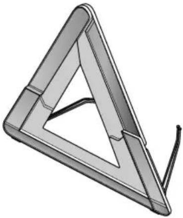
natural_image
3D rendering of a triangular mechanical component with internal cutouts and a curved end (no text or symbols)Thewarningtrianglesuppliedwithyourcarisstowedin theloadspace.
If you havetostopy your carontheroadinan emergency, you must place awarning triangle about between 50 and 100 metres behind the cartowarnotherroad users of your position.
EMERGENCYINFORMATION
EmergencyStarting
UsingBoosterCables

NEVERstarttheenginebypushingortowing.

MakesurethatBOTHbatteriesareofthe samevoltage(12volts),andthatthebooster cablesareapprovedforusewith12voltcar batteries.

Ensuresparksandnakedlightsarekeptwell awayfromtheenginecompartment.
Usingboostercables(jumpleads)fromadonorbattery, orabatteryfittedtoadonorvehicle,istheonlyapproved methodofstartingacarwithaflatbattery.
If the battery from on or vehicle is to be used, the vehicle should be parked with their battery locations adjacent to one another. Ensure that the two vehicles do not touch.
StartingtheVehicle

Ensure that each boostercable connection is securely made. Theremust benorisk of the clips accidentally slipping from the battery terminals (as a result of engine vibration, for example), this could cause sparking, which could lead to fire ore explosion.
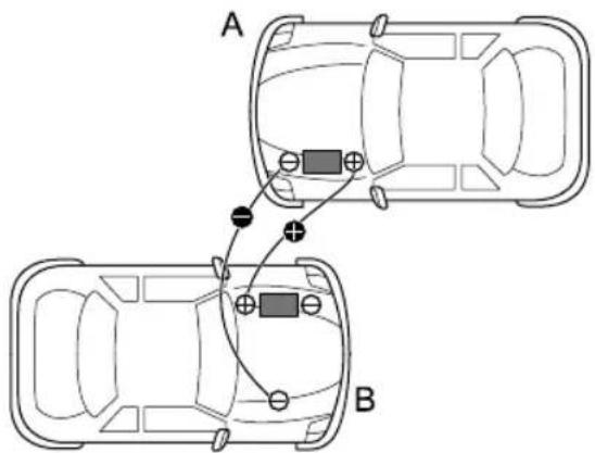
EMERGENCYINFORMATION
RemovetheignitionkeyandswitchoffALLelectrical equipmentofBOTHvehicles,thenfollowtheinstructions below:
ConnecttheREDboostercablebetweenthepositive (+) terminalsofbothbatteries.Connectthe BLACKboostercablefromthenegative (-) terminabthedonobattery(A)tagoodearth point(anenginemountingorotherunpaintedsurface,forexample),atleast0.5mfromthebatteryandwell awayfromfuelandbrakelinesonthedisabledvehicle (B).
IMPORTANT
DONOTconnectaboostercabletothenegative (-)terminalofthedischargedbattery! This may result in damage the electrical components.
2Check that the cables are clear of moving part so both engines, then start the engine of the donor vehicle and allow it to die for a few minutes.
3Nowstarttheengineofthevehiclewiththe dischargebatter(DONO Tranthenginfor morethan 10 seconds).
④once botengineareunningormallyallowthem toidlefortwominutesbeforeswitchingofftheengine ofdonovehiclandisconnectinghebooster cablBONOTswitchonanyelectricalcircuits onthepreviouslydisabledvehicleuntilAFTERthe boostercableshavebeenremoved.
Disconnecting boostecable musbeexact reversals for procedures connected, i.e. disconnect the BLACK cable from the earthpoint on the disabled vehicle FIRST.
IMPORTANT
NEVERurnonanyelectricalequipmentthe startedvehiclebeforeremovingtheboostercables.
EMERGENCYINFORMATION
VehicleRecovery
T owingEye

DONOTuseatowropethatistwisted-anyunwindingforcecouldunscrewthefronttowingeye.
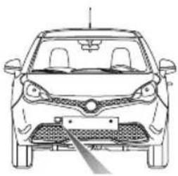
natural_image
Front view line drawing of a compact car (no text or symbols)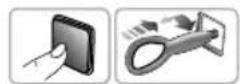
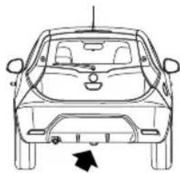
natural_image
Front view line drawing of a car with a black arrow pointing to the side (no text or symbols)Yourcarisequippedwitharemovabletowingeyeatthe front,andwithafixedtowingeyeattherear. Thetowing eyeisstoredinthetoolkitbeneaththeluggageareafloor whennotinuse.
T ofitthetowingeye,removethesmallcoversetintothe bumper,thenscrewthetowingeyeintothethreadedhole inthebumperbeam(seeillustration).Ensurethetowing eyeisfullytightened!
EMERGENCYINFORMATION
Note: Thetowingeyecovermaybesecuredtothe bumperbyaplasticcord.
Bothtowingpointsareintendedforusebyqualified recoveryspecialiststoassistintherecoveryofyourcar shouldabreakdownoraccidentoccur.Theyarenot designedfortowingothervehicles.
T owingforRecovery
If your car need stobetowed, most qualified recovery specialists will use wheel lift equipment to suspend the front wheels, while therear wheels remain on the ground. However, if it is necessary for the cart but owed with all four wheels on the ground, abide by the following procedure:
BeforeBeingT owed:

DONOTremovetheignitionkeywhilethe carisbeingtowedonfourwheels—asthiswill preventthesteeringwheelfrombeingturned.
I Switchtheignitionontoposition2toenablethebrake lights, wipersanddirectionindicatorstobeoperatedif necessary. If, duetoanelectricalfault, it is considered unsafetoswitchtheignitionon, thecarwillneedto berecoveredonatrailer.
2Placethegearleverinneutral.
3Releasethehandbrake.
EMERGENCYINFORMATION
WhileBeingT owed:

Thetowingdistancesshouldnotexceed30 miles(48km). Whiletowingforrecovery, the towingvehicleshouldneverexceed30mph (48km/h)
Withouttheengine running, greater effort will be required to operate the brake pedaland turn the steering wheel. Longer stopping distances will also be experienced.
T ransporterorT railerwithRope

DONOTuseatowropetotowyourcar behindanothervehicle.
If your caristobetransported on the back of a trailer or transporter, it must be secured as illustrated.
Positionthecaronthetrailer,applythehandbrakeand placethegearleverinNeutral.Fitwheelchocks(1)as shown,thenpositiontheantisliprubberblocks(2)around thecircumferenceofthetyre.
Fitthelashingstraps(3)aroundthewheelsandsecureto thetrailer.Tightenthestrapsuntilthecarissecurelyheld.
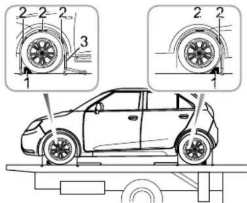
EMERGENCYINFORMATION
T yreRepair&WheelReplacement
T oolldentification\*
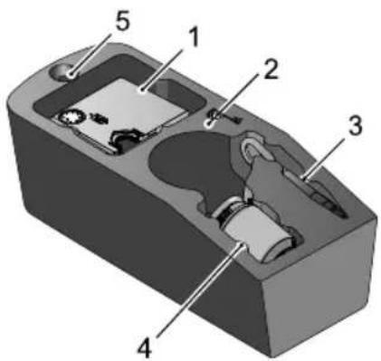
4 Tyrerepairsealant
5Lockingwheelboltadapter
I Electricaircompressor
2 Wheelnutcoverremovaltool
3 T owinghook
EMERGENCYINFORMATION
T yreRepair\*
I RemovethestickerontheT yreSealantBottleand attachittothesteeringwheeltoremindthedriver nottoexceed50MPH(80km/h).(Figure 1)
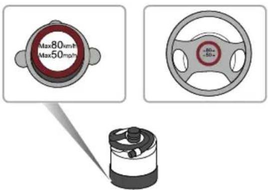
2Connecttheairhoseoftheelectriccompressorto thetyresealantbottle, fittheT yreSealantbottle (Upright)intotheslotonthecompressor.Remove thevalvedustcapfromtheflattyreandconnectthe fillerhosefromthetyresealantbottletothetyre
valve.EnsurethatthepowerswitchoftheElectric aircompressorisswitchedoff(i.e.,press“O”),then inserttheplugfromthecompressorintothecentre consolepowersocket.
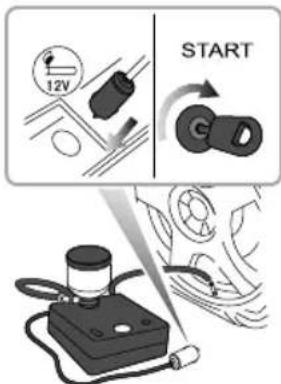
Netsobttendischarge,
recommendedtokeeptheengineerunning.
Switchorthepowerswitchofthelectricompressor (i.e press-")startumpingalarintthe tyre. Thetyresealantbottlewillbecomeemptyafter
EMERGENCYINFORMATION
approximate30seconds. Thetyreshouldreach the specifiedinflationpressureof2.2bar(34psi)within 5or10minutes.
Note: The pressure gaugemaybrieflyreach6 bar(87psi), thenthepressurebeginstodropto normal.
4Whentherequiredpressureisreached,switchoffthe powerswitchoftheelectriccompressor(i.e.,press "O").
Note: If therequired pressure cannot be reached within 10 minutes, pleased disconnect the compressor, drivethe vehicle 10 metres (33 feet) approx forwardor backward to allow these sealant to spread with in the theyre. If therequired pressure can still not bereached, they reisseverely damaged and you should seek assistance from the MGA authorised Repairer.
No consecutive operation of Electric air compressor for more than 10 minutes may result in damaggetothecompressor.
Nadernocircumstance should you continue your journey with a deflated tyre. Driving vehicle with a deflated tyre is extremely dangerous.
5Removethetyresealantbottlefromtheslotinthe compressor, disconnect the hose from the they re valve, removethe compressor plug from the centre console powersocket, return the yrerepair kit to its stowage tray.
6Aftersuccessfullyaddingsealanttothetyre,drive immediatelyforashorttime(aroundoneminute)this willallowthesealanttodistributeevenlyinsidethe tyre.Continuedrivinganddonotexceed50MPH (80km/h).Afterafurther 10minutes,findasafeplace tostopandrecheckthetyrepressure.
If the request has dropped down 0.8 bar (11.6 psi), donot continued driving, seek assistance instead.
If the pressure is greater than 0.8 bar (11.6 psi) after a 10 minutes drive, correct the property of the tyrepressur label and continue Check again after another 0 minute drive of 1.8 bar (26. lpsi) cannot
EMERGENCYINFORMATION
bereached, donotcontinuedrive, seekassistance instead. Donotexceed50MPH(80km/h).
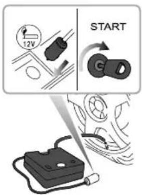
- If the pressure has not dropped after these second 10 minutes drive, continue. If 1.8 bar (26.1 psi) cannot bereached, donot continued drive, seek assistance instead. Donot exceed 50 MPH (80 km/h).
Note: DONOTremoveforeignobjects(eg. screws, nails) from the theyre. Thetyrerepairsystem must only be used when the foreign object is in the
treadpattern(A), DONOTattemptarepairwhen thedamageisinthesidewallofthetyre(B).
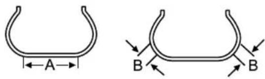
Attheearliestopportunitygetthetyrereplacedbyan AuthorisedMGRepairerortyrespecialistandreplacethe usedtyresealantbottlewithanMGapprovedsealant.
EMERGENCYINFORMATION
AccessingtheSpareWheelandT ools *
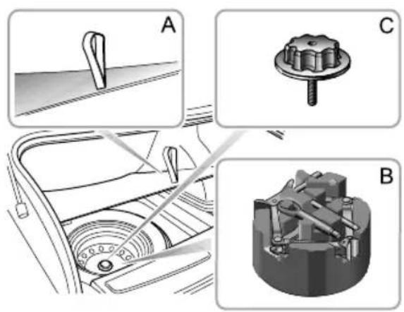
T oaccessthesparewheelandtools:
I Usetheliftingstraptoraisetheluggagecarpet.(A)
2Removethetooltray.(B)
3Unscrewthesparewheelclampandliftthewheelfrom theboot.(C)
T oolldentification*
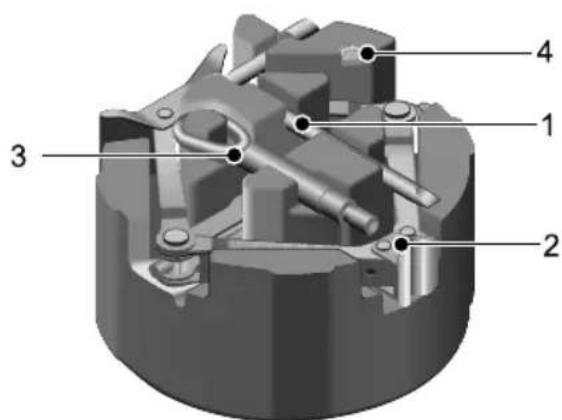
I Wheelnutwrench.
2Jack
3Fronttowingeye.
4Trimremovaltool
EMERGENCYINFORMATION
ChangingaWheel
If possible, choose as a safe placet to stop away from them in thoroughfare. Always ask your passenger to get out of the car and wait in a safe area away from other traffic.
Switchonhazardlights.lfavailable,positionawarning triangleoraflashingamberlight50to150metres(150 to500ft)behindyourvehicletowarnapproachingtraffic.
Beforechangingawheel,ensurethefrontwheelsareinthe straightaheadposition,applytheparkingbrakeandselect firstgear.
Observethefollowingprecautions:
- Ensurethejackispositionedonfirm,levelground; NEVERonsoftground,orovermetalgratingsor manholecovers.DONOTplaceadditionalmaterial betweenthejackandtheground,thismayjeopardise thesafetyofthejackingoperation.
•lfjackingonaslopeisessential,placechocksatthefront andrearofthewheeldiagonallyoppositetheonetobe removed.
- NEVERjackthecarwithpassengersinsideorwitha caravanortrailerconnected!
PositioningtheJack

NEVERworkbeneaththecarwiththejack astheonlymeansofsupport. Thejackis designedforwheelchangingonly!

NEVERjackthecarusinganyjackingpoints othethathdesignatepointshown. Seriousdamagetothecarcouldresult.
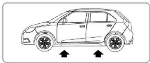
natural_image
Side view line drawing of a car with two upward arrows indicating motion or movement (no text or symbols)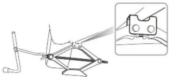
natural_image
Technical line drawing of a mechanical clamp or bracket assembly with an inset showing a close-up view of the component (no text or symbols present)EMERGENCYINFORMATION

Avoidaccidentalcontactwithanyunderbody parts,especiallyhotexhaustsystem components.
Positionthejackonfirmlevelgroundunderthejacking pointnearestthewheeltoberemoved. Notethatthejack headmustfitintothecorrespondingrecessinthesillplate (seeinsetinillustration).
Turningthejackscrewbyhand,adjustthejackuntilthejack headfitssnuglyontothesillinthecorrectarea.Ensurethat thebaseofthejackisinfullcontactwiththelevelground.
ChangingtheWheel

Checksparetyrepressureregularly.Always checktyrepressuresafterchangingawheel.

Ensure that wheel nuts are tightened to correct torque of 105-115Nm.
I Before raising the car, use the wheel wrench to slacken each of the wheel nut half at turnanti-clockwise.
Note: Depending on the style of wheels fitted may be necessary to remove wheel nut covers, centrecapor wheel tripset the special tool located within the tool kittoremov there relevant trim type.
Notæ:helockingwheelnutsonvehiclesfitted withthem(onelockingwheelnutperwheel)can onlybeloosenedortightenedbyusingtheadapter provided.*
2Turnthejackscrewclockwisetoraisethecaruntilthe tyreisclearoftheground.
3Removethewheelnutsandplacetheminthetooltray topreventthemfrombeinglost.
4Removetheroadwheel.
NotAvoidingHEELsacdownthe ground-thesurfacemaybescratched.
5Fitthesparewheelandtightenthewheelnutsuntilthe wheelisseatedfirmlyagainsttthehub.
EMERGENCYINFORMATION
6Lowerthecarandremovethejack, thenFULLYtighten thewheelnutsinadiagonalsequence.
7Finally, return the tool to the tool tray and the wheel (facedown) to the well in the load space floor
Note: Recheck the wheel nuttorque after initial tightening.
Note: Consult your MGA authorised Repairerortyre specialist for areplacement tyre, as soon as possible.
EMERGENCYINFORMATION
FuseReplacement
Fuse
Fusesaresimplecircuitbreakerswhichprotectthevehicle electricalequipmentbypreventingtheelectricalcircuits frombeingoverloaded.Ablownfuseindicatesthatthe itemofelectricalequipmentitprotectsstopsworking.
Thelocationandcapacityofeachfusearelabeledonthe fuseboxlids.
Checkasuspectfusebyremovingitfromthefuseboxand lookingforabreakinthewireinsidethefuse.
Wesuggestthattakesomesparefusesforreplacement. SparefusesareavailablefromMGAuthorisedRepairers.
HealthyandBlownFuses
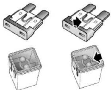
IMPORTANT
- NEVERattempttorepairablownfuse.ALWAYS replaceafusewithoneofthesamerating.
- Ifareplacedfusefailsimmediately,pleasecontactan MGAuthorisedRepairerassoonaspossible.
EMERGENCYINFORMATION
FuseBox
Therearetwofuseboxesinthevehicle:
- PassengerCompartmentFuseBox (belowtheglove boxatthefrontpassengerside).
-EngineCompartmentFuseBox (attheleftsideofthe EngineCompartment).
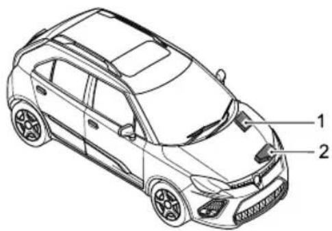
IPassengerCompartmentFuseBox
2EngineCompartmentFuseBox
PassengerCompartmentFuseBox
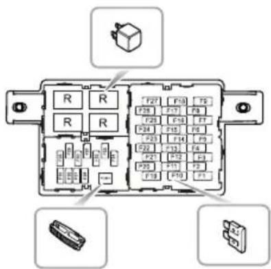
CheckorReplaceaFuse
I Switchofftheignitionswitchandallelectrical equipment, disconnectthebatterynegativecable.
2Remove the closing panel below the glovebox to gain access to the refuse box.
Presthusextractiotootnthfushead andpulltoremovethefusAblownfusecanbe recognisedbyabreakinthewire.
EMERGENCYINFORMATION
4Replacetheblownfusewithasamerating.
FuseSpecification
| Fuse | Rating | Function |
| F1 | 20A | RearWiperRelay,RearWasher Relay(LHD) |
| F215A | CentreConsolePowerSocket | |
| F35AD | DiagnosticSocket | |
| A F4 | ABS,IPK,DC/DC,ECM,BCM,SAS,YawRateSensor | |
| F5 | 10ARearWasherRelay(RHD) | |
| A F6 | AirCondition,BlowerRelay,CentreConsolePowerSocketRelay,HeatedRearWindowRelay,HeadlampLevellingSwitch ,PassengerSideAirbagDisabled Indicator | |
| F7 | 15ASuperLockRelay | |
| F810A | SRSDCU | |
| Fuse | Rating | Function |
| F910A | InertiaSwitch | |
| F105A | LeftPositionLamp,SwitchIllumination,LeftTailLamp | |
| F11 | 5AFront | Interior/MapLamp |
| F125A | RearLicensePlateLamp,RightTailLamp,SwitchIllumination,RightPositionLamp | |
| F1320A | BrakePedalSwitch,ReverseLampSwitch | |
| F1415A | CDLMotor(Lock),TailgateMotor(Lock) | |
| F15 | 10A | ReserveFuse |
| F1615A | CDLMotor(Unlock),TailgateMotor(Unlock) | |
| F17 | 10A | Horn |
| F1810A | BCM,RearWasherRelay,DriverDoorCombinationSwitch,IPK , InCarEntertainment | |
| F195A | LeftBrakeLamp,HighMountedBrakeLamp |
EMERGENCYINFORMATION
| Fuse | Rating | Function |
| F2020A | LeftRear | WindowLiftSwitch |
| F215A | RightBrakeLamp | |
| F2220A | RightRear | WindowLiftSwitch |
| F235A | ECM,BCM | |
| F2425A | Passenger | WindowLiftSwitch |
| F2520A | RearScreenHeating | |
| F2625A | DriverDoorCombinationSwitch | |
| F2710A | ExteriorRearViewMirrorHeating | |
| F2815A | InCarEntertainment | |
| F29 | - | - |
| F3010A | AirCondition | |
| F31 | - | - |
| F3210A | IPK | |
| Fuse | Rating | Function |
| F33 | - - | |
| F345A | DAB | |
| F355A | ReserveFuse | |
| F3610A | ReserveFuse | |
| F3715A | ReserveFuse | |
| F3820A | ReserveFuse |
EMERGENCYINFORMATION
EngineCompartmentFuseBox
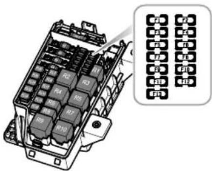
CheckorReplaceaFuse
I Switchofftheignitionswitchandallelectrical equipment, disconnectthebatterynegativecable.
2Pressthebuckletoremovethefuseboxlid.
3Pressthefuseextractiontoolontothefusehead andpulltoremovethefuse.Ablownfusecanbe recognisedbyabreakinthewire.
4Replacethefusewithasamerating.
FuseSpecification
| FuseRatingFunction | ||
| F1 | 10A | RightFrontLowBeamLamp |
| 5A F2 | Post-OxygenSensor,InletCamSolenoid,ExhaustCamSolenoid | |
| F3 L0A FrontLow BeamLamp | ||
| F4 A0A Condition CompressorClutch | ||
| F5 | E0M | |
| 5A F6 | CoolingFanRelay,PurgeControlValve,AirConditionCompressorClutchRelay,FuelPumpRelay,StopStartSwitch | |
| F7 | 30A | FrontWiperEnableRelay,FrontWiperSpeedControlRelay |
| F85A OxygenSensor | ||
| F915A | DayTimeRunningamp,IPKIllumination | |
EMERGENCYINFORMATION
| FuseRatingFunction | ||
| FI010A | RightFrontHighBeamLamp,IPK Illumination | |
| FII | 10ALeftFrontHighBeamLamp | |
| FI230A | IgnitionCoils,Injectors,ECM | |
| FI330A | - | |
| FLI | 2000A | Alternator,Passenger CompartmentFuseBoxFuse F4、FLII |
| FL250A | ASCSECU(Pump) | |
| FL340A | CoolingFan | |
| FL460A | PassengerCompartmentFuseBox FusF20、F22、F24、F26 | |
| FL5 | 80A | PassengerCompartmentFuseBox FusF1、F3、F4、F5、F7、F9、F25、F27,RearScreenHeating Relay |
| FL625A | ASCSECU(Valve) | |
| FL7 | 50AlgnitionSwitch | |
| FL825A | Common | UnlockandLockRelays |
| FL930 | ADC/DCC | Converter |
| FL1025A | HornRelay,WasherPumpRelay | |
| FL11 | 30ABlowerMotor,AirConditioning | |
| FL1225A | DippedBeamRelay | |
| FL1330 | AStarterRelay | |
| FL1425 | ABCMIndicators&RearFogLamp | |
| FL15 | 30A | PositionLampRelay,DayTime RunningLampRelay,Engine CompartmentFuseBoxFuseF9、F10、F11,PassengerCompartment FuseBoxFuseF10、F12 |
| FL16 | - - | |
EMERGENCYINFORMATION
BulbReplacement
BulbSpecification
| LampBulb | Specifications |
| HeadlampHigh/LowBeamH460/55W | |
| SideLight | W5W5W |
| FrontDirectionIndicators | PY21W21W |
| SideRepeater(InMirror) | WY5W5W |
| ReverseLamps | H21W21W |
| RearFogLamps | W21W21W |
| Stop/TailLampsPR21/5W21/5W | |
| LampBulb | Specifications |
| LicensePlateLampsW5W5W | |
| InteriorLamp | C10W10W |
| RearDirectionIndicators | P21W21W |
| LoadSpaceLampR10W10W | |
| HighMountedStopLamp | W5W5W |
| DaytimeRunningLamp | LED(non-serviceable) |
EMERGENCYINFORMATION
BulbReplacement
Beforereplacinganybulb,turnoffthelightingswitchto avoidanypossibilityofashortcircuit.
Note: Only replace bulb with the sametype and specification.
TakecareNOTtotouchtheglasswithyourfingers;always useaclothtohandlethebulb.lfnecessary,cleantheglass withmethylatedspiritstoremovefingerprints.
Ifindoubt,whenreplacingbulbs,contactaspecialist workshop.
Thebulbremovalprocedureisasfollows(Theinstallation procedureisinreverseorder,soitwillnotbedescribed here),forotherbulbsnotlistedandtobereplaced,askan MGAuthorisedRepairerforhelp.
LoadSpaceLamp
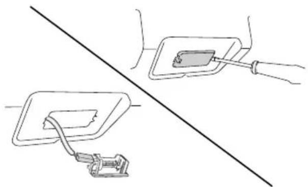
natural_image
Line drawing showing two methods of connecting a cable to a device, one with a cable and the other with a cable inserted (no text or symbols)Insertasmallflat-bladedscrewdriverintotheindenton oneofthenarrowsidesofthelensandcarefullyremove theunitfromitslocation.
EMERGENCYINFORMATION
LicencePlateLights
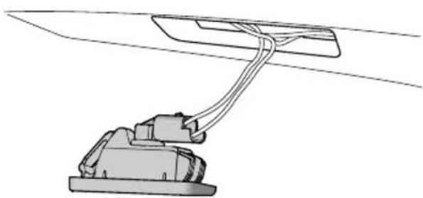
natural_image
Technical line drawing of a mechanical assembly with a lever and base mount (no text or symbols)l Insertasmallflat-bladedscrewdriverintothenarrow gapatonesideofthelicenseplatelight,pryslightly andremovethelens.
2Removethebulbfromthebulbholder.
InteriorLamp
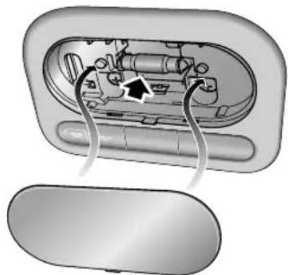
natural_image
Diagram of an open electronic device showing internal components and wiring, with no visible text or symbols.I Useaflat-bladescrewdrivertopythefrontendof thelens, andremovethelens.
2Removethebulbfromthebulbholder.
Maintenance
178Maintenance
182Bonnet
183 EngineCompartment
185Engine
187CoolingSystem
189 Brakes
191PowerSteering
193Battery
197Washers
199 Wiper
202Tyres
207CleaningandVehicleCare
MAINTENANCE
Maintenance
RoutineServicing
Thesafety, reliability and performance of your car will depend partly on how well it is maintained.
Youmustensurethatmaintenanceiscarriedoutwhen requiredandaccordingtotheinformationcontainedinthe 'WarrantyandMaintenanceManual'.
Servicing
Themessagecentreshowsthedistanceremainingbefore thenextservice.
Thedistancedisplaycommencesatthemaximumservice intervaldistanceforyourmarket,andprogressively reducesinincrementsof25miles(50km)asthecaris driven,untilzeroisreached.Therelevantserviceshould becarriedassoonasthedistancedisplayshowszero.
After the completion of each service, the distance display will be reset to the maximum service interval distance for your market.
Note: Because the service interval display reduces in increment of 25 miles (50 km), it is possible to undertake short journey without triggering any movement from the display.
Note: If a service is not carried out (orthedisplay is not reset), the distance indicator, having reached zero, will remain at zero until it is reset.
ServiceHistory
Refertothe 'Warranty and Maintenance Manual' for details. Ensure your MGA authorised Repairersigns and stamp the Service History after each service.
BrakeFluidReplacement
Thebrakefluidrequiresreplacementeverytwoyears, irrespectiveofthedistancethecarhastravelleyour MGAuthorisedRepairerwillreplacethebrakefluidatthe servicenearestttotheconclusionofeachtwoyearperiod.
CoolantReplacement
Theenginecoolant(anti-freezeandwatersolution)needs tobereplacedeveryfouryearsregardlessofthedistance thecarhastravelled.YourMGAuthorisedRepairerwill replacethecoolantattheservicenearesttototheconclusion ofeachfouryearperiod.
EmissionControl
Yourcarisfittedwithemissionandevaporativecontrol equipmentdesignedtomeetspecificterritorialandlegal requirements.Incorrectenginesettingsmayadversely affectexhaustemissions,engineperformanceandfuel consumption,aswellascausinghightemperatures,which couldresultindamagetothecatalyticconverters,and engine.
IMPORTANT
Youshouldbeawarethatunauthorisedreplacement, modificationortamperingwiththisequipmentbyan ownerormotorvehiclerepairercouldresultinthe manufacturer'swarrantybeingdeemedasinvalid.In addition,enginesettingsmustnotbetamperedwith.
OwnerMaintenance

Anysignificantorsuddendropinfluidlevels, oruneventyrewear,shouldbereported withoutdelay.Forfurtherinformation,refer toanMGAuthorisedRepairer.
Inadditiontotheroutineservicesreferredtoppreviously, anumberofsimplechecksmustbecarriedoutmore frequently. Youcancarryoutthesechecksyourselfand adviceisgivenonthepagesthatfollow.
DailyChecks
•Operationoflights,horn,directionindicators,wipers, washersandwarninglights.
•Operationofseatbeltsandbrakes.
- Lookforfluiddepositsunderneaththecarthatmight indicatealeak.
WeeklyChecks
•Engineoillevel
MAINTENANCE
Note: The engine oil level should be checked more frequently if the car is driven for prolonged periods at high speeds.
•Coolantlevel.
- Brakefluidlevel.
•Powersteeringfluidlevel.
•Screenwasherfluidlevel.
•Tyrepressuresandcondition.
- Operateairconditioning.
SpecialOperatingConditions
Ifthecarisfrequentlyusedindustyconditionsoroperated inextremeclimateswheresubzeroorveryhighambient temperaturesarenormal,morefrequentattentionmay needtobepaidtoservicingrequirements.
If you need to carry out special maintenance operations, refer to Parts and Warranty Statement on the MG Distributors website or contact your MG authorised repairer.
SafetyintheGarage

Coolingfansmaycommenceoperatingafter theengineisswitchedoff,andcontinue operatingforanumberofminutes.Keep clearofallfanswhileworkingintheengine compartment.
If you need to carry out maintenance, observ the followingsafety precautions at all times:
- Keepyourhandsandclothingawayfromdrivebeltsand pulleys.
- Ifthecarhasbeendrivenrecently, DONOTTOUCH exhaustandcoolingsystemcomponentsuntiltheengine hascooled.
• DONOTT OUCHelectricalleadsorcomponents while the engine is running, or with the key in the ignition. - NEVERleavetheengine runninginanunventilated area -exhaustgasesarepoisonousandextremelydangerous.
•DONOTworkunderneaththecarwithawheel changingjackastheonlymeansofsupport.
MAINTENANCE
- Ensuresparksandnakedlightsarekeptawayfromthe enginecompartment.
- Wearprotectiveclothing, including, wherepracticable, glovesmadefromanimperviousmaterial.
- Removemetalwristbandsandjewellerybeforeworking intheenginecompartment.
•DONOTallowtoolsormetalpartsofthecartomake contactwiththebatteryleadsorterminals.
PoisonousFluids
Fluidsusedinmotorvehiclesarepoisonousandshouldnot beconsumedorbroughtintocontactwithopenwounds. Theseinclude:batteryacid,antifreeze,brakeandpower steeringfluid,petrol,diesel,engineoilandwindscreen washeradditives.
Foryouwnsafety, ALWAYSreadandobeyall instructionsprintedonlabelsandcontainers.
UsedEngineOil
Prolongedcontactwithengineoilmaycauseseriousskin disorders,includingdermatitisandcanceroftheskin. Washthoroughlyaftercontact.
Usedengineoilshouldbedisposedofcorrectly.Incorrect disposalcancauseathreattotheenvironment.
MAINTENANCE
Bonnet
OpeningtheBonnet
DONOT drivewhenthebonnetisretained onlybythesafetycatch.
1 From the inside of the car, pull the bonnet release handle(A).
2Pushthesafetycatchleverlefttoreleasethesafety catch(B).
3Raisethebonnetandthentthesupportstayintothe cutoutintheundersideofthebonnetrmly.
ClosingtheBonnet
Replacethesupportstayinitsretainingclipthenlowerthe bonnet,allowingittodropforthelast20–30cmtoits closedposition.
Byattemptingtoliftthefrontedgeofthebonnet,checkif thelockisfullyengagedafterclosingthebonnet.Ifitisnot fullyengaged,youmustrepeattheoperation.
WarningWhentheBonnetisOpen
If the bonnet catch is not fully engaged, the warning light that indicates the vehicle panels are not closed will be illuminated when the ignition is in position (seewarning lights and indicators in Instruments and Controls chapter)
EngineCompartment
EngineCompartment(LHD)

While working in the engine compartment, always observethes safety precautions listed under "Safety in the Garage", referto "Maintenance" in "Service and Maintenance" section.
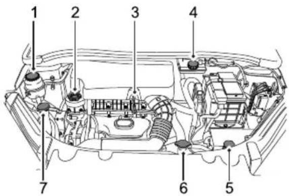
IPowersteeringreservoir(black cap)
2Engineoilfiller(yellowcap)
3Engineoildipstick(yellow)
4Brakereservoir(yellowcap)
5Coolingsystemexpansiontank (whitecap)
6Coolingsystempressurecap (silverywhite)
7Washerreservoir(bluecap)
MAINTENANCE
EngineCompartment(RHD)

While working in the engine compartment, always observethes safety precautions listed under "Safety in the Garage", referto "Maintenance" in "Service and Maintenance" section.
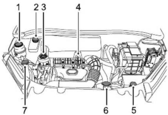
IPowersteeringreservoir(black cap)
2Brakereservoir(yellowcap)
3Engineoilfiller(yellowcap)
4Engineoildipstick(yellow)
5Coolingsystemexpansiontank (whitecap)
6Coolingsystempressurecap (silverywhite)
7Washerreservoir(bluecap)
MAINTENANCE
Engine
EngineOil
ACEASpecification
UseengineoilmeetingACEAspecificationAI/BI, to ensure optimum protection for your engine, alternatively seek advice from the manufacturer.
Note:Mixingoiladditiveswiththeengineoilisnot recommendedandcoulddamagetheengine.
EngineOilLevelCheckandT opUp

Drivingthecarwiththeengineoillevel ABOVEtheuppermark,orBELOWthelower markonthedipstick,willdamagetheengine.

T akecaretoavoidspillingengineoilontoa hotengine-afiremayresult!
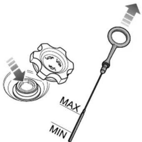
MAINTENANCE
Checktheoillevelweeklyandtopupwithoilifnecessary. Ideallytheoillevelshouldbecheckedwiththeenginecold andthecarrestingonlevelground.However,ifthecaris inuseandtheengineisalreadywarm,waitforatleastfive minutesafterswitchingoffbeforecheckingthelevel.
I Withdrawthedipstickandwipethebladeclean.
2Slowlyinsertthedipstickandwithdrawagaintocheck thelevel,whichshouldNEVERbeallowedtofallbelow the'MIN'markonthedipstick.
3T otopup, removeofftheoilfillercapandaddoilto maintainalevelbetweenthe'MAX' and 'MIN'marks onthedipstick.
4Waitforfiveminutesandthenrecheckthelevel, addingmoreoilifnecessary—DONOTOVERFILL!
5Finally, ensurethedipstickandfillercaparereplaced.
Forengineoiltypeandcapacityrefertothe'T echnicalData' Chapter.
IMPORTANT
Check the engine oil more frequently if the car is driven at high speeds for prolonged periods.
MAINTENANCE
CoolingSystem
CoolantCheckandT opUp

DONOTremovethereservoircapwhenthe coolingsystemishot-escapingsteamor watercouldcauseseriousinjury.
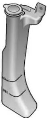
natural_image
3D rendered mechanical part with labeled sections (Max, Min) and a central cylindrical feature (no text or symbols beyond labels)Thecoolantlevelshouldbecheckedweeklywhenthe coolingsystemiscoldandwiththecarrestingonlevel ground.Ifthelevelislowerthan'MIN'mark,openthe
expansiontankandtopupthecoolant. The level should not be higher than 'MAX' mark.
Note: Preventcoolantcomingintocontactwiththe vehiclebodywork, coolantwilldamagepaint.
If the coolant level falls appreciably during a short period, and aleakissuspected, arrange for MGA authorised Repair to examinethecar.
CoolantSpecification
Pleaseusethecoolant(mixofwaterandantifreeze)which isrecommendedandcertifiedbythemanufacturer.Please refer to 'RecommendedFluidsandCapacities'.
Note: In an emergency to pup the cooling system with clean water, but be aware of the resultant reduction infrost protection performance. DONOT topup or refill with other anti-freeze formulations.
Note: DONOT topuporrefillwithrustinhibitoror othercoolantadditives.
MAINTENANCE
Antifreeze

Antifreezeispoisonousandcanbefatal ifswallowed-keepcontainerssealed and outofthereachofchildren. Ifaccidental consumptionissuspected, seekmedical attentionimmediately.

Preventantifreezecomingintocontact withtheskinoreyes.Ifthisoccurs,rinse immediatelywithplentyofwater.
Brakes
BrakeFluid

Brakefluidishighlytoxic-keepcontainers sealedandoutofthereachofchildren. Ifaccidentalconsumptionofbrakefluidis suspected,seekmedicalattentionimmediately.
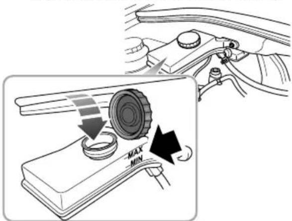
Brakefluidreservoir(RHD)

Preventbrakefluidcomingintocontactwiththe skinoreyes.Ifthisoccurs,rinseimmediately withplentyofwater.
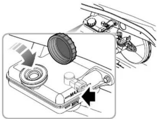
Brakefluidreservoir(LHD)
MAINTENANCE
Thebrakefluidlevelshouldbecheckedweeklywhenthe systemiscoldandwiththecaronlevelground.
Thefluidlevelcanbeseenthroughthereservoirneck andshouldbemaintainedasclosetothe'MAX'markas possible.Donotallowtheleveltodropbelowthe'MIN' mark.
Note: Brakefluidwilldamagepaintedsurfaces. Soak upanyspillagewithanabsorbentclothimmediately andwashtheareawithamixtureofcarshampooand water.
BrakeFluidSpecification
Usethebrakefluidwhichisrecommendedandcertified bythemanufacturer.Referto'RecommendedFluidsand Capacities'in'T echnicalData'.
IMPORTANT
Thebrakefluidmustbereplacedeverytwoyears.
PowerSteering
PowerSteeringFluidCheckandT opUp

Powersteeringfluidishighlytoxic.Keep containerssealedandoutofthereach ofchildren.Ifaccidentalconsumptionof fluidissuspected,seekmedicalattention immediately.

Ifpowersteeringfluidshouldcomeinto contactwiththeskinoreyes,rinse immediatelywithplentyofwater.
Thefluidlevelshouldbecheckedeveryservice. This shouldbedonebeforetheengineisstartedwhenthe systemiscoldandwiththefrontwheelspointingstraight ahead.
Wipethillecapleanprevendinfromentering theeservoRemovehillecapnd,singlean lint-freecloth,wipethedipstickclean.Refitthecapfully andemovagaincheckthuilevefecessary, topupwithafluidmeetingspecificationuntilthelevelis
between the upper and lower marks on the dipstick (see illustration).
No Powersteeringfluidwilldamagepainted surfacesSoakupanspillagewithabsorbentcloth immediatelyandwashtheareawithamixtureofcar shampooandwater.
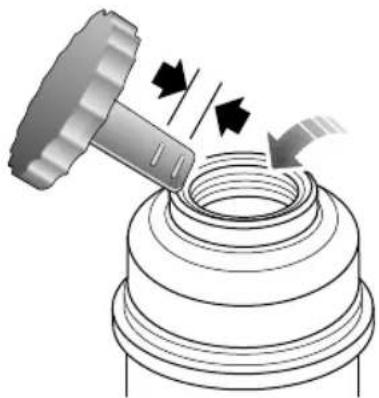
natural_image
Mechanical component diagram showing a turning tool interacting with a threaded cylindrical component (no text or symbols)MAINTENANCE
IMPORTANT
Takecarenottospillpowersteeringfluidontoahot engine-afiremayresult.
PowerSteeringFluidSpecification
Usethepowersteeringfluidwhichisrecommended andcertifiedbythemanufacturer.Pleasereferto 'RecommendedFluidsandCapacities'in'T echnicalData' chapter.
Battery
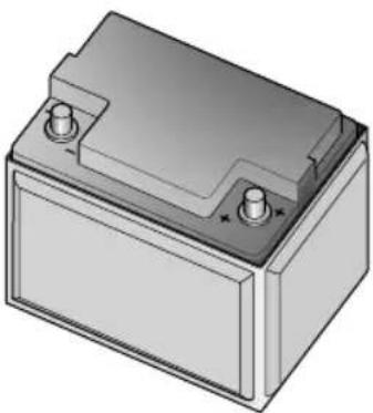
natural_image
3D rendering of a rectangular battery housing with two terminals and mounting holes (no text or symbols visible)T oaccessthebattery,raisethebonnet,releasethefixings andmovethetopofthebatterycoveraside.
BatterySafety
Batteriescontainsulphuricacid,whichiscorrosive.Wear suitableprotectiveequipmentwhenhandlingbatteriesto protectyoureyes,skinandclothing.
Ifaspillageoccurs:
- Onclothingortheskin-removeanycontaminated clothingimmediately,flushtheskinwithlargeamounts ofwater,andseekmedicalattentionurgently.
• Intheeyes-flushwithcleanwaterimmediatelyforat least 15minutes.Seekmedicalattentionurgently. - SwallowingbatteryacidcanbefatalunlessIMMEDIATE actionistaken-seekmedicalattentionurgently.
BatteryDisconnectionandReplacement
Note: NEVERruntheenginewiththebattery disconnected, or disconnectthebatterywhilethe engineisrunning.
IfabatteryrequiresreplacementcontactanMG AuthorisedRepairer.Onlyfitareplacementbatteryofthe sametypeandspecificationastheoriginaltomaintainthe correctvehiclefunctionality.
Before disconnecting or removing the battery, ensure that the starters switch and electrical equipment turned off.
Disconnect the negative (-) cable first and then the positive (+) cable (when reconnecting, connect the positive cable first and then the negative cable).
MAINTENANCE
When lifting the battery from the car, keep the battery upright at all times.
Makesureboththebatteryclampingplateandretaining straparefittedsecurely,thiswillpreventthebatteryfrom movingintheeventofanaccidentorsuddenstop.
Note: On vehicles fitted with Stop/Start, after battery disconnection it will be necessary to leave the vehicle in locked condition for 4 hours in order to assess the battery condition. Failure to this will result in the loss of the Stop/Start function.

The battery must be disposed of using an approved, used batteries can be harmful to the environment. There are recycled by a professional company. Please use an MGA authorised repair or more details.
BatteryCharging
Note: DONOTchargethebatteryifitissuspectedof beingfrozen.
Asthebatteryages, it may not retain its charge as effectively as when it was new. Car that are used infrequently, or are used excessively for short journey motoring, or operation in cold climates, may need the battery to be charged regularly.
PreChargingBatteryAppearanceCheck : : :
If the outercasing is broken or there is a leak, DO NOT charge the battery and replace it after finding the reason.
If the terminal is broken, DONOT charge the battery and replace it after finding there reason.
DONOTattempttochargea'bulging'or'distorted' battery.
Pri: charging unterminal sefeom corrosion, applypetroleum jelly to terminal to help prevent corrosion.
ChargingNotes:
•Alwayswearsafetyglasseswhenconnectingor disconnectingabatterycharger.
•Alwaysensuretheretheareaiswellventilated.Ensure thechargingbatteryhasadequatespaceanddoesnot 'over-heat'.
•DONOTsmokeinthevicinityofachargingbattery, andensuresparksandnakedlightsarekeptwellaway fromtheenginecompartment.
- Beforecharging,connectthepositivecableatfirst.
Aftercharging,disconnectthenegativecableatfirst.
BatteryChargingOperation:
Note: When charging oemergency starting always ensure then negative lead has good connection to a body earth away from the battery (refer to these section 'Emergency Starting' in the 'Emergency Information' Chapter).
- Ifchargingthebatterywhilstonthevehicle,please connectthebatterychargernegativeleadtothevehicle bodyensuringagoodconnection.
-
Ensure all terminals are free from corrosion.
-
Only suitable battery chargers can be used - please consult an MGA authorised Repairer for details.
- During the charging process the battery temperature MUST NOT exceed 40°C.
• DONOTattempttochargeabatteryattemperatures below0°C.
BatteryMaintenance
DONOTleaveelectriccomponentsswitched onwhentheengineisnotrunning,the batterymaybecomeflatandyouwillnotbe abletostarttheengine.
The batter designed to maintain and so topping-up is unnecessary.
Note: If the vehicle is stored from more than 1 month, removal the earth lead from the battery. Makes sure that the ignition switch has been turned off before connecting disconnecting heart on vehicles fitted with Stop/Start, when connecting the earth lead again, the vehicle must be left in a locked state for 4 hour store-calibrated the battery condition.
MAINTENANCE
FailuretoadheretowthiswillinhibittheStop/Start functionality.
Washers
WindscreenWasherCheckandT opUp

Somescreenwashproductsareflammable. DONOTallowscreenwashtocomeinto contactwithnakedflamesorsourcesof ignition.

Whenfillingthewasherreservoirdonotallow thefluidtocontactanypaintedsurfaces.If anycontactismade,washimmediatelywith shampooandwater.
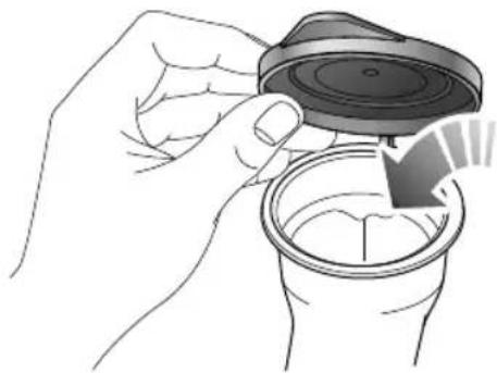
natural_image
Illustration of a hand holding a container with a lid and arrow indicating rotation (no text or symbols)Checkthereservoirleveleveryweek.
Note: DONOTuseananti-freezeorvinegar/water solutioninthewasherreservoir—anti-freezewill damagepaintworkwhilevinegarwilldamagethe windscreenwasherpump.
IMPORTANT
• Only usethewasher fluid recommended by the manufacturer. Misuse of washer fluid in winter may caused damage to the washer motorduetofreezing.
• Using the washerswitch when there is now a washer fluid in the reservoir may cause damage to the washer motor.
- Operatingthewiperswhenthewindscreenaredry maycausedamagetothewindscreenandwipers. Pleasespraythewasherfluidbeforestartingthe wipers
MAINTENANCE
WasherNozzles
Operatethewasherperiodically to check if the windshield washernozzles are clean and they are in the correct direction.
The windshieldwashernozzlesareconfigured during the production, sogenerally there is noneed for adjustments. But, if necessary, you may insert an needle into the nozzle hole, and locate them nozzle by prying it gently, enable the washing fluids spraying directly in the center of the windshield.
If thenozzleisobstructed, insertaneedleorthinmetal wire into the holetoremovetheobstruction.
WashingFluidSpecification
Usethewasherfluidrecommendedandcertifiedby themanufacturer.Referto"RecommendedFluidsand Capacities"inthe"TechnicalData"section.
Wiper
WiperBlade
| IMPORTANT |
| •Grease,siliconandpetrolbasedproductsimpairtheblade'swipingcapability.Wasthewiperbladesinwarmsoapywaterandperiodicallychecktheircondition. |
| •Cleanthewindscreenfrequently,donotusewiperstoremovestubbornoringraineddirt,itwillreducetheireffectandtheirlifespan. |
| •Ifsignsofhardnessorcrackingintherubberarefound,orifthewipersleavestreaksorunwipedareasonthescreen,thenthewiperbladesshouldbereplaced. |
| •Cleanthewindscreenregularlywithanapprovedglasscleanerandensurethescreenisthoroughlycleanedbeforefittingreplacementwiperblades. |
| •Onlyfitreplacementwiperbladesthatareidenticaltotheoriginalspecification. |
| •Cleaniceandsnowfromaroundwipersandensuretheyarenotfrozenorotherwisestickingtothewindscreenbeforeattemptingtooperatethem. |
MAINTENANCE
ReplacingFrontWiperBlades
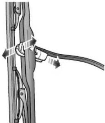
natural_image
Diagram of a rope knot being inserted into a vertical pole, showing rope routing and movement arrows (no text or labels)I Liftthewiperarmawayfromthewindscreen.
2Squeezethelocatingtagstobothsidesasarrowedand pivotthebladeawayfromthewiperarm.
3Unhookthebladefromthewiperarmanddiscard.
4Locatethetipofthenewwiperbladeintheslotinthe wiperarm.
5Pivotthewiperbladetowardsthearmuntilthe locatingtagsengage.
6Checkthatthebladeisfittedcorrectlytothearm beforepositioningonthewindscreen.
ReplacingRearWiperBlades
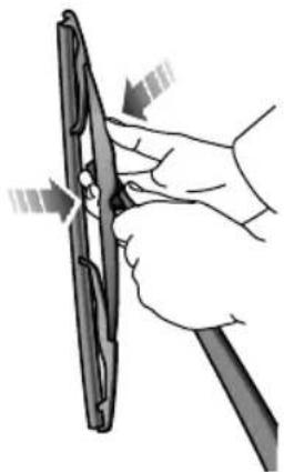
natural_image
Illustration of a hand holding a tool with arrows indicating motion or force (no text or symbols)I Liftthewiperarmawayfromthetailgate.
2Pivotthebladeawayfromthewiperarmasarrowed.
3Unhookthebladefromthewiperarmanddiscard.
MAINTENANCE
4Locatethetipofthenewwiperbladeintheslotinthe wiperarm.
5Pivotthewiperbladetowardsthearmuntilthe locatingtagsengage.
6Checkthatthebladeisfittedcorrectlytothearm beforepositioningonthetailgate.
MAINTENANCE
T yres
Overview
•Takeextracarewhenusingnewtyresforthefirst300 miles(500km).
- Avoidexcessivecorneringatspeed.
- Regularlychecktyresfordamageandforeignobjects-removeanyforeignobjectsfromthetread.
- Avoidtyrecontactwithoils,greaseandfuel.
- Ensurevalvecapsarealwaysfitted.
- Ifthetyreistoberemovedalwaysmarkthetyre/wheel orientationtoensurecorrectrefitment.
NewT yres
Newtyresmaynothavethesameadhesionpropertiesof theoldtyres,pleasetakeextracarefor500km.This actioncouldbenefittyrelife.Tyreorrimdamagecan happenunnoticed.Ifabnormalvibrationsorhandlingis experienced,oryouthinktyreorrimdamagehasoccurred pleasecontactanMGAutorisedRepairer.
DirectionalT yres
Directionaltyresaremarkedwith'directionofrotation'(DOR).T omaintainhandlingcharacteristics,tyre performance,lowroadnoiseandextendtyrelife, tyres/wheelsmustalwaysbefittedwithindicationarrow showingthecorrect'DOR'.
T yreLife
Correcttyrepressuresandmoderatedrivingstylecan extendtyrelife.Recommendations:
- If the vehicle is restored for a lengthy time, please move at least one time in two weeks to 'rotatethetyres'
- Tyrepressures should be checked regularly when the tyres are cold.
- Avoidcorneringatexcessivespeeds.
- Regularlychecktyresforabnormalwearpatterns.
The following factors affect theetyrelife.
T yrePressures
Incorrecttyrepressurescanresultinpoordriving characteristicsandashortenedtyrelife.T yrepressures
shouldbecheckedatleastonceamonth, and onceprior to each long-distance journey.
DrivingStyle
Excessivelyharshaccelerationandbrakingwhilstcornering willreducetyrelife.
WheelBalance
Shakingorvibrationofthevehicleorsteeringmechanism canindicateoutofbalancewheels.Itisimportanttorectify thisquicklyastopreventwearonsteeringandsuspension componentsandshortentyrelife.
WheelAlignment
Incorrectwheelalignmentcancauseexcessivetyrewear and affect vehicles safety. If the tyresshowsignsofabnormal wearseek advice from MGA authorised repairer.
CaringforY ourT yres

DEFECTIVETYRESAREDANGEROUS! DONOTdriveifanytyreisdamaged,is excessivelyworn,orisinflatedtoanincorrect pressure.
Always drivewith consideration for the condition of the tyres, and regularly inspect the thread and sidewalls for any sign of distortion (bulges), cuts or wear.
Note: If possible, protecttyres from contamination by oil, grease and fuel.
T yrePressures

Beforealongdistancejourney,thetyre pressuremustbechecked.
Checkthepressures(includingthesparewheel)atleast everymonth,whenthetyresarecold.
Ifitisnecessarytocheckthetyreswhentheyarewarm, youshouldexpectthepressurestohaveincreasedby0.3 to0.4bar(4.35to5.8psi).Inthiscircumstance,NEVERlet
MAINTENANCE
airoutofthetyresinordertomatchtherecommended pressures(cold).
Valves
Keepthevalvecapsscreweddownfirmly-thypreventdirt fromenteringthevalve.Checkthevalveforleaks(listen foratell-talehissing)whenyoucheckthetyrepressure.
PuncturedT yres
Yourvehicleisfittedwithtyreswhichmaynotleakif penetratedbyasharpobject,providedtheobjectremains inthetyre.Ifyouareawareofthisoccurring,reducespeed immediatelyanddrivewithcautionuntilthesparewheel canbefitted,orrepairsundertaken.
Note: If the sidewallothetyreisdamagedor distorted, replacethetyreimmediately, donot attemptarepair.
T yreWearIndicators
Tyresfittedasoriginalequipmenthavewearindicators mouldedintothetreadpatternatseveralpointsaround thecircumference.
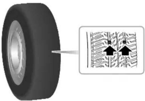
natural_image
Diagram showing a tire with an arrow pointing to a textured surface, and a magnified inset illustrating the machining process (no text or symbols present)Whenthetreadhasworndownto 1.6mm,theindicators willcometothesurfaceofthetreadpattern,producing theeffectofacontinuousbandofrubberacrossthewidth ofthetyre.
IMPORTANT
AtyreMUSTbereplacedassoonasawearindicator becomesvisible.
ReplacementT yres

DONOTreplacethewheelswithwheels ofanyothertype.Alternativewheels,ofa differentspecification,mayadverselyaffect thecar'sdrivingcharacteristics.
Alwayshavereplacementwheelsandtyresbalancedbefore use.
WheelFitmentRotation
Inordertobalancetyrewear, it may benefit from rotating tyreposition. Wheels can be swapped front to ear in ordertoevenspread tyrewear across all tyres.

flowchart
graph TD
    A["Terr 1"] --> B["Terr 2"]
    C["Terr 3"] --> D["Terr 4"]
    E["Terr 5"] --> F["Terr 6"]
    G["↑"] --> A
    H["×"] --> I["←"]
    J["↓"] --> K["←"]
DirectionaltyresCANNOTbeswappedfromsidetoside.
SnowChains
Unsuitablesnowchainscoulddamagethetyres, wheels, suspension, brakesorbodyworkofyourcar.
Inuse, always observethe following precautions:
•Fitsnowchainstothefrontwheelsonly.
- Thethicknessofsnowchainsshouldn'texceed20mm.
MAINTENANCE
•Alwaysadheretothesnowchainfittingandretensioning instructionsandthespeedlimitationsforvaryingroad conditions.
•DONOTexceedspeedsof50km/h.
- Avoidtyredamageandexcessivechainwearby
removingsnowchainswhendrivingonsnowfreeroads.
Note: If you drive on the snowy and icy roads, it is recommended to use wintertyres. Consultant MG
AuthorisedRepairerfordetails.
CleaningandVehicleCare

Observeallsafetyprecautionsoncleaning products;donotdrinkfluidsandkeepthem awayfromtheeyes.
WashingY ourCar

Somehighpressurecleaningsystemswill penetratedoor, windowseals, and damage lockmechanisms. DONOTaimwaterjets directly at componentsthatmightbeeasily damaged.
Inordertopreservethepaintfinishonyourcar, please observethefollowingcarepoints:
•DONOTusehotwatertowashthecar.
•DONOTusedetergentsorwashingupliquid.
• Inhotweather, DONOTwashthecarindirectsunlight.
- When using a hose, DONOT aim the water directly at window, door seals, orthrough wheel apertures onto the brake components.
Ifthecarisparticularlydirty,useahosetoflushgrime and gritfromthebodywork,priortowashing. Then,washthe carusingcoldorlukewarmwatercontainingagoodquality washandwaxshampoo.Alwaysuseplentyofwaterto ensurethatgritisflushedfromthesurfaceandnotground intothepaintworAfterwashing,rinsethebodywork withcleanwateranddryoffwithachamoisleather.
CleaningtheUnderside

DONOTuseahighpressurehosetoclean theenginecompartment-damagetothe car'selectronicsystemsmayoccur.
Fromtimetotime, but particularly during winter months when salthas been used on theroads, use ahosetowash the underside of the car. Flush away accumulation of mud and thoroughly clean those areas where debriscane easily collect (wheel arches and panelseams, forexample).
RemovingT arSpots
Usewhitespirittoremovetarspotsandstubborngrease stainsfromthepaintwork. Thenwashtheareaimmediately withsoapywatertoremovealltracesofthespirit.
MAINTENANCE
BodyProtection
Afterwashing,examinethepaintworkfordamage.Ifthe damagehasrevealedbaremetal,useacolouredprimer first,thenapplythecorrectcolourbasecoatandfinish offwithalacquerpencil,ifappropriate.Carryoutthis treatmentafterwashingbutbeforepolishingorwaxing.
Moreextensivedamagetopaintorbodyworkmust berepairedinaccordancewiththemanufacturer's recommendations.Failuretodothiswillinvalidatethe Anti-CorrosionWarranty.Ifindoubt,askyourMG AuthorisedRepairer.
PolishingthePaintwork

DONOTusecarpolishcontainingcoarse abrasives—thesewillremovethepaintfilm anddamagetheglossfinish.
Occasionally treat the paints surface with an approve polish containing the following properties:
Verymildabrasivestoremovesurfacecontamination withoutremovingordamagingthepaint.
Fillingcompoundsthatwillfillscratchesandreduce theirvisibility.
Waxtoprovideaprotectivecoatingbetweenthepaint andtheelements.
Notfpossible, avoidapplyingpolishorwax productstowindowglassandrubberseals.
WiperBlades
Washinwarmsoapywater.DONOTusespiritorpetrol basedcleaners.
WindowsandMirrors
Regularlycleanallwindows,insideandout,usingan approvedglasscleaner.
Windscreen: In particular, clean the outside of the screen with glass clean after washing the car with wash and wax products, and before fitting new wiper blades.
Reascreenclearthensidewith soft cloth usingside tosidemotion to avoid damaging the heating elements.
Note: DONOTscrapeoruseabrasivecleanersonthe insideoftherearscreen—thiswilldamagetheheating elements.
Mirrors: Washwithsoapywater. Useaplasticscraperto removeice. DONOTuseabrasivecleaning compounds ormetalscraper.
VehicleGraphicsCare
WashRegularly
Washwheneverthevehicleappearsdirty.Contaminants allowedtoremainonthevehiclegraphicsmaybemore difficulttoremoveduringcleaning.Rinseoffasmuchdirt andgritaspossiblewithalowpressuresprayofwater.
Useawet, non-abrasivedetergents such as 3M™ CarWash Soap 39000 or Meguia's NXT Generation® CarWash, or Deep Crystal® CarWash and as soft, clean cloth or sponge.
Rinsethoroughlywithcleanwater.T oreducewater spotting,immediatelyuseasiliconesqueegeetoremove water(takingcarearoundtheedgesofthegraphics)to removewaterandfinishwithacleanmicrofibercloth.
AutomatedCarWash
Brush-typecarwashesarenotrecommendedastheycan abradethegraphicsandcausetheedgestoliftorchip,as wellasdullingthegraphic'sappearance.
MAINTENANCE
PressureWashing
Theuseofapressurewasherisnotrecommendedasthis maydamagethevehiclegraphic.
DifficultContaminants
Softendifficultcontaminantssuchasbugsplatter,bird droppings,treesapandsimilarcontaminantsbysoaking themforseveralminuteswithhotsoapywater.Rinse thoroughlyanddry.Iffurthercleaningisneeded,testone oftheseproductsinaninconspicuousareatoensureno damagethegraphics:Meguiar'sGoldClass™ Bug&Tar Removeror3M™ CitrusBaseCleaner.Spotcleanthe contaminants.Donotuseroughscrubbingorabrasive tools,whichwillscratchhegraphics.Washandrinseoff allresidueimmediately.
FuelSpills
Wipeoffimmediately to avoid degrading the graphics and adhesive. Then wash, rinse and dry as soon as possible.
CleaningtheInterior
PlasticMaterials
Cleanplastic-faced materials with diluted upholstery cleaner, then wipewith adamp cloth.
Note: DONOTpolishdashboardcomponents—these shouldremainnon-reflective.
CarpetandFabrics
Cleanwithdilutedupholsterycleaner-testaconcealed areafirst.
Leather
Cleanleathertrimwithwarmwaterandanon-detergent soap.Dryandpolishtheleatherwithadry,clean,lint-free cloth.
Note: DONOTuspetrodetergents, furniture creamsorpolishesascleaningagents.
MAINTENANCE
InstrumentPack, Clock, AudioSystemand
NavigationDisplay
Cleanwithadryclothonly.DONOTusecleaningfluids orsprays.
AirbagModuleCovers

DONOTallowtheseareastobefloodedwith liquidandDONOTusepetrol,detergent, furniturecreamorpolishes.
T oprotectdamagetotheairbagSRS, the following areasshouldbecleanedsparinglywithadampclothand upholsterycleanerONLY:
•Steeringwheelcentrepad.
• Areaofdashboardcontainingthepassengerairbag.
- Areaofroofliningandfrontpillarfinisherswhich enclosethesideheadimpactprotectionmodules.
SeatBelts

DONOTusebleaches, dyesorcleaning solventsonseatbelts.
Extendthebelts,thenusewarmwaterandanon-detergent soaptocleanAllowthebeltstodrynaturally;DONOT retractthemorusethecarunittheyarecompletelydry.
TechnicalData
214 TechnicalDataDimensions
215Weights
216 MajorParametersofEngine
217RecommendedFluidsand Capacities
218WheelAlignment(Unladen Condition)
218 WheelsandTyres
218TyrePressures(Cold)
TECHNICALDATA
T echnicalDataDimensions
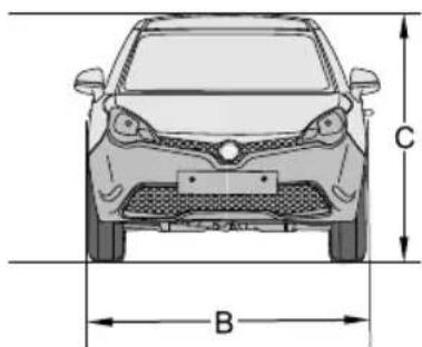
natural_image
Front view of a car with labeled dimensions B and C (no text or symbols beyond labels)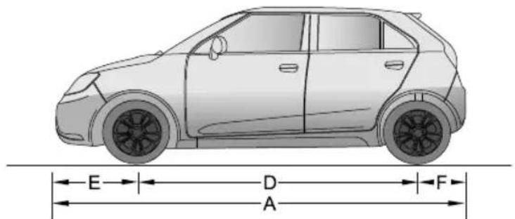
| Item,units | Parameter |
| OveralllengthA,mm4018 | |
| OverallwidthB,mm(includingexterior-viewmirror) | 1728(1887) |
| OverallheightC(unladen),mm1507 | |
| WheelbaseD,mm | 2520 |
| FrontOverhangE,mm | 859 |
| RearOverhangF,mm | 639 |
| Item,units | Parameter |
| Frontwheeltrack,mm | 15051513(7J×16) |
| Rearwheeltrack,mm | 14931501(7J×16) |
| Minimumturningcirclediameter,kerb-to-kerb | 10.4 |
| Fueltankcapacity,l | 45 |
| Luggagecapacity,l | 256 |
Weights
| Item,unitsParameter | |
| Personincab,person5 | |
| Unladenvehicleweight(kerb),kg|126to|165 | |
| Grossvehicleweight,kg|665to|685 | |
| ExtraGrosstrainweight,kg|865to|885 |
Note: PleaserefertothevehicleidentificationlabelfortheexactGTW(grosstrainweight)foryourvehicle.
T owingWeights
| Item,unitsParameter | |
| T owinglimitun-braked,kg | 200 |
| T owinglimitbraked,kg | 200 |
TECHNICALDATA
MajorParametersofEngine
| Item,unitsParameter | |
| Bore×Stroke,mm×mm75×84.8 | |
| Capacity,11.498 | |
| Compressionratio10.5:1 | |
| Maximumpower,kw | 78 |
| Enginespeedtodevelopmaximumpower,rev/min6000 | |
| Maximumtorque,Nm | 137 |
| Enginespeedtodevelopmaximumtorque,rev/min4700 | |
| Noloadidlespeed,rev/min670±50 | |
| C Fueltype,RON/CN |
oEN228SPEC
RecommendedFluidsandCapacities
| NameFluidtype | Capacity | |
| Engineoil,l | A1/B15W-204.5 | |
| Enginecoolant,l | Glycol(OAT)4.9(0.7forexpansiontank) | |
| Manualtransmissionfluid,IMTF941.8 | ||
| Brakefluid,IDOT4(LowViscosity)0.73 | ||
| Powersteeringfluid,l | DexronIII | 0.92 |
| Washerfluid,IQx35 | ||
| Aircondi234jngrefrigerant,g |
TECHNICALDATA
WheelAlignment(UnladenCondition)
| Item | Parameter | |
| Front | Camberangle | -0°36'±45' |
| Kingpincasterangle | 3°33'±45' | |
| T oein(oneside) | 0°8'±15' | |
| Kingpininclination (nonadjustable) | 12°22'±45' | |
| Rear | Camberangle | -1°16'±45' |
| T oein(T otal) | 0°29'±20' | |
T yrePressures(Cold)
| TyreUnladen | |
| FrontWheel | 210kPa/2.1bar/31psi |
| RearWheel | 210kPa/2.1bar/31psi |
WheelsandT yres
| WheelSize5.5J×146.5J×167 | 0J×16 | |
| TyreSize185/70 | 195/55 | 195/55 |
| R14 | R16 | R16 |
A
ABS (Anti Lock Braking System) 136
ABS Warning Light 22,137
Accessory Power Socket 45
Aerial (Antenna) 69, 86
Air Conditioning (Climate Control) 50
A/C Air Distribution 50, 51
A/C Air Distribution Control 55–57
A/C Air Recirculation 58
Air Vents 50–51
Airbag SRS 95–102
Airbag SRS Warning Light 21, 99
Airbag, Driver And Passenger 95
Airbag – Side/Head/Curtain 99
Ambient Temperature 12, 16
Anti Freeze 188
Audio Equipment 59–86
Audio Sound Settings 63, 74
Automatic Function – Courtesy Lights 44
Auto Lights 26
Aux Devices – Audio 69, 84
Average Fuel Consumption 13, 17
Average Speed 14, 18
B
Band Button - Audio Controls 65, 78
Battery - Handset 113
Battery Charging 21, 194
Battery Disconnection And Removal 193-195
Battery Maintenance 193-195
Blower (Heater) 52
Blower (A/C)* 55
Bluetooth Settings 77
Bonnet Opening 182
Booster Cables 155
BDW (Brake Disc Wiping) 134
Brake Fluid 178, 189
Brake Fluid Specification 190
Brake Lights 174
Brake Warning Light 22
Brakes 134
Braking in an Emergency 136
Bulb Replacement 175
Bulb Specification 174
C
Capacities 217
Catalytic Converter 128
CD Player 60, 70
INDEX
CD Playing 67
Changing a Wheel and Tyre 165 - 167
Child Proof Locks 115
Child Restraints and Seats 103 - 110
Cleaning - Car Interior 210 - 211
Cleaning - Paintwork 207 - 209
Climate Control 50
Clock and Time 74, 76
Cold Climates 123
Coolant Check, Top-Up And Replacement 178, 187
Coolant Specification 187 - 188
Cooling System 187
Cruise Control* 25, 145, 146
Cup Holders 48
D
Daily Checks 179
Data - Technical 214 - 218
Daytime Running Lights 29
Dimensions 214
Dipped Beam Headlights 26, 28, 172
Dipstick 185
Direction Indicator Bulb - Front 172
Direction Indicator Bulb - Rear 172
Direction Indicator Lights 20, 28
Disabling Passenger Air-Bag 100
Door Open Indicator 24
E
Ejecting A CD 67, 82
Ejecting USB Device Safely 68, 83
EBA (Electronic Brake Assist) 135
EBD (Electronic Brake Force Distribution) 135
Emission Control 179
Engine Fault Light 22, 23
Engine Immobilisation 24, 116
Engine Number 3
Engine Coolant Temperature 23
Engine Oil 185-186
Environmental Driving 125
F
Fast Forward – Audio Controls 67, 82
Fog Light Bulb - Rear 174
Fog Lights - Rear 21, 27
Follow-Me-Home Lights (Lights Off Delay) 29
Foot Brake 134
Front Passenger Lower Cubby Box 47
Front Wiper Operation 32
Front Wiper Blade Replacement 199
Fuel Consumption 13, 17
Fuel Cut-Off Switch 131
Fuel Filler 131
INDEX
E
Fuel Filling 131
Fuel Gauge 8
Fuel Specification 216
Fuel System 130
Fuses, Replacement And Colour 168
Fuse Specifications 170-172
Fuse Box (Passenger Compartment) 169-171
Fuse Boxes (Engine Compartment) 172-173
G
Gear Change Display 10
Gear Change Warning Indicator 10
Glovebox 47
H
Handbrake 137
Hazard Warning Lights 29, 30
Hazard Warning Triangle 154
Head Restraints 89
Headlight Bulb 174
Headlight Flash 28
H
Headlight Levelling 30, 31
Heated Mirrors 37
Heated Rear Screen 53, 57
Heavy Loads 151
Hill Hold Function 135
Horn 36
↓
Identification Numbers 3
Ignition Switch 121
Indicators 28
Instrument Pack 7
Instrument Panel Storage 47
Intelligent Stop Start, Automatic Shutdown 142
Intelligent Stop Start, Automatic Start 142
Intelligent Stop Start, Failure 144
Intelligent Stop Start, Isolation control 141
Intelligent Stop Start, Operation 141
Intelligent Stop Start, Status Lamp 25
Intelligent Stop Start, Warning Lamp 25
Interior Door Handles 120
Interior Lights 44, 176
INDEX
Jacking and Jack Positioning 165 - 167 Jump Leads 155- 156 Jump Starting 155- 156
↓
Key 112
K
Lighting Switch 26
Load Carrying |51-152
Loadspace Light Bulb 175
Locking 112, 116, 117
Locking - Speed Related 120
Locking Wheel Nuts 160, 166
Low Oil Pressure 21
L
M
Main Beam Headlights 20, 28, 174
Maintenance 127, 177-211
Manual Transmission 133
Message Centre 9-19
Mirrors - Door 37- 38
Mirrors - Interior 39
Mirrors Cleaning 208-209
Mirrors - Folding 39
Mislock 117
N
Next Service 14, 18
Number Plate Lamps 174, 176
O
Odometer 11, 15
Oil Level Check – Engine 185
Oil Top-Up 185
"One-Touch" Windows 43
Owner Maintenance 179-180
P
Parking Aid 147-148
Particle/Pollen Filter 51
Passenger Air-Bag Disabling 100, 101
Phone Connection Via Bluetooth® 84
Poisonous Fluids/Gases 181
Power Steering Fluid Check And Top-Up 191-192
R
Rain Sensor* 32
Rear Fog Guard Lights 21
Rear Light Bulbs 174
Rear Seats - Folding 91
Rear Wiper Operation 33
Rear Wiper Blade Replacement 200
Rear Window Isolation Switch 42
Recirculation 54 58
Recommended Fluids 217
Recovery 157
Remote Handset 116 - 119
Reverse Light Bulbs 174
Routine Servicing 178
Running-In 125
S
Safety In The Garage 180
Search Tuning – Audio Controls 65, 78
Seat Belt Care 93
Seat Belt Pre-Tensioners 94
Seat Belts 92 - 94
Seat Belt Warning 21
Seat Cushion Height (Driver Only) 90 - 94
Seats 88 - 90
Steering Column Adjustment 35
Steering Lock 121-122
Sun Visor 41
T
TA - Traffic Announcement Button – Audio Controls, 66, 79
Tachometer 8
Telephones 85-86
Thirty-Minute Play Function - Audio Controls 62, 73
Tool Kit Identification 160
Top Tether Restraint 109
Towing Eyes 157
Towing Weights 215
Towing For Recovery Precautions 157-159
Track Search - Audio Controls 67, 81
Traction Control (TC) 24, 139, 140
Transporter or Trailer Lashing 159
Transmission Number 3
Trip Computer 10-19
Trip Recorder 11, 15
Tyre Pressures 202, 203, 218
Tyre Repair 161-163
TPMS - (Tyre Pressure Monitoring System) 14, 18, 24, 149
Tyre Wear Indicators 204
Tyres 202–206, 218
INDEX
U
Unlocking 112, 116, 117, 119
USB Socket 68, 82
Used Engine Oil 181
V
Vanity Mirrors 41
Variable Delay - Wipers 32
Vehicle Identification Number 3, 4
Vehicle Information Display 10, 11, 15
Vehicle Recovery 157-159
Ventilation 50, 51
VIN Plate 3, 4
W
Warning Lights 20-25
Warning Triangle 154
Washer Jets, Fluid and Top-Up 197 - 198
Washing the Car 207
Weekly Checks 179
Weights 215
Wheel Changing 165
Wheels 218
Wheel Nut Torque 165
Wheel Alignment 218
Windows 42 - 43
Window Lift Switch 42
Windscreen Wipers 199
Wiper Blade Replacement 200-201
Wiper Controls 32-34


- CONTENTS
- Preface....I
- Introduction......
- VehicleIdentificationInformation....3
- I InstrumentsandControls....5
- InstrumentsandControlsOverview......6
- InstrumenPack....7
- MessageCentre....9
- 4Seats&Restraints....87
- EconomicalandEnvironmentalDriving....125
- CatalyticConverter....128
- FueSystem....130
- Manual transmission....133
- BrakeSystem....134
- 6EmergencyInformation....153
- CoolingSystem....187
- Brakes....189
- PowerSteering....191
- Battery....193
- Washers....197
- Introduction
- TheOwner'sHandbook
- StatusatTimeofPrinting
- SymbolsUsed
- Warning
- Important
- Note
- PREFACE
- Asterisk
- IllustrationInformation
- InanEmergency
- Rememberthebreakdownsafetycode
- VehicleIdentificationInformation
- VINLocation
- EngineNumberLocation
- T ransmissionNumberLocation
- VehicleIdentificationLabel
- InstrumentsandControls
- InstrumentsandControlsOverview
- InstrumentPack
- T achometer
- Speedometer
- FuelGauge
- MessageCentre
- GearSelectionDisplay
- VehicleInformationInImperialMessage Centre\*
- Odometer
- T ripDistanceAandT ripDistanceB
- AmbientT emperatureDisplay
- FuelRangetoEmpty
- InstantaneousFuelConsumption
- AverageFuelConsumption
- AverageSpeed
- NextService
- TPMSReset
- T ripDistanceAandTripDistanceB
- WarningLightsandIndicators
- MainBeam-Blue
- SideLamps-Green
- DirectionIndicators-Green
- RearFogLight-Y ellow
- Airbag-Red
- SeatBeltWarning-Red
- LowOilPressure-Red
- BatteryCharging-Red
- ABS-Y ellow
- ParkingBrake/BrakeSystemLight-Red
- EngineEmissionFault-Y ellow
- EngineCheck-Y ellow
- EngineCoolantT emperatureWarningLight-Red/Blue
- StabilityControSystem(SCS)Y ellow
- StabilityControSystem(SCS)OffYellow
- T ractionControl(TC)WarningOff-Y ellow
- T yrePressureMonitoringSystem(TPMS)-
- Y ellow
- EngineImmobilizer/KeyBatteryLow-Red
- PanelOpeningWarning-Red
- CruiseControl-Y ellow/Green\*
- IntelligentStop-StartEnergy-SavingSystem
- Status-Green
- MalfunctionWarning-Y ellow
- LightsandSwitches
- MainLightSwitch
- SideLights,T ailLights,InstrumentPackLight
- Headlights
- AUTOLights \*
- FogLightsSwitch
- RearFogLights
- DirectionIndicators/MainBeamLever
- DirectionIndicators
- HeadlightMainandDippedBeam
- HeadlightsFlash
- FollowMeHome(HeadlightsDelayedOFF)
- DaytimeRunningLights
- HazardWarningLights
- HeadlightLevelling-ManualAdjustment
- T ouringAbroad
- WipersandWashers
- SingleWipe
- VariableDelay-intermittentwipe
- RainSensor \*
- FrontWindscreenWasher
- SteeringColumn
- SteeringColumnAdjustment
- Horn
- Mirrors
- DoorMirrors
- MirrorGlassManualAdjustment \*
- HeatingElements \*
- InteriorRear-viewMirror
- SunVisor
- Windows
- WindowOperation
- 'One-T ouch'Down\*
- InteriorLights
- InteriorLamp
- AutomaticOperation
- ManualOperation
- CentreConsolePowerSocket
- StorageEquipment
- Instructions
- StorageBox
- InstrumentPanelStorageBox
- FrontPassengerLowerStorageBox \*
- CupHolder
- ClimateControl
- Ventilation
- Particle/PollenFilter
- Vents
- CentreVents
- SideVents
- HeaterControls \*
- ControlPanel
- Blower
- T emperatureControl
- AirDistribution
- HeatedRearScreen
- AirRecirculation
- AirConditioningControls \*
- A/CButton
- Note:
- PowerOn/Off
- vents.
- Defrost/Demist
- AudioSystem
- CDPlayer \* (LowLine)
- UseInstructions
- BasicOperation
- On/OffPower
- 30MinutesPlayFunction
- Mute/Pause
- SelectMode
- VolumeAdjustment
- MenuOperation
- BASS
- TREBLE
- BALANCE
- FADER
- EQ
- LOUDNESS
- AlternativeFrequenciesSetting
- RegionSetting
- ClockTimeSetting
- EnhancedOtherNetworksSetting
- TrafficAnnouncementVolume
- TimeSetting
- PlayingMode
- FolderMode
- RadioFunction
- ModeSelection
- BandSelection
- T une
- SearchTuningMode
- ManualTuningMode
- Pre-setTuningMode
- StoreStation
- ManualStore
- AutoStore
- TA(TrafficAnnouncement)
- CDPlaying
- LoadingaCD
- T rackSearch
- FastForward/Rewind
- EjectingCD
- USB
- USBConnection
- USBPlaying
- USBRemoval
- AUX
- AUXInputPlaying
- Antenna
- CDPlayer \* (HighLine)
- AudioSoundSetting
- MIDDLE
- Clock, TimeandDate
- ClockorDateMode
- RDSSettings
- BluetoothSettings
- BluetoothActivation
- BluetoothPairing
- PairedList
- IncomingCallvolume
- ContrastAdjustment
- DABSetting
- DABStationListOrder
- ServiceFollowing
- DABBackgroundScan
- FM/MW
- SearchT uningMode
- RDSInfo.
- DAB\*
- StationSelect
- EnsembleMode
- AlphabeticalMode
- Pre-setT uningMode
- EnsembleandStationListView
- iPod/iPhone®
- iPod/iPhone® Connection
- iPod/iPhone® PlayingMode
- RemovalofiPod/iPhone®
- Bluetooth
- Pairing
- BluetoothConnection
- PhoneBookDownload
- BluetoothMusic
- Accept/RejectIncomingCall
- BluetoothFunctionMenu
- CallHistory
- Phonebook
- DialNumber
- BluetoothSetting
- Seats&Restraints
- Seats
- CorrectSeatingPosition
- HeadRestraints
- Forward/RearwardAdjustment
- HeightAdjustment \*
- BackrestAdjustment
- FoldingtheRearSeats
- RearSeatBackrests'LatchSecure'Indicators
- SeatBelts
- FasteningtheBelt
- ReleasingtheBelt
- CheckingSeatBelts
- ReplacingSeatBelts
- SeatBeltPre-tensioners
- Note: Theseatbeltpre-tensionerswillINOTbe activatedbyminorimpacts.
- AirbagSupplementaryRestraint System(SRS)
- Airbags
- AirbagDeployment
- FrontSeatSideAirbags
- SideHeadImpactProtectionAirbags
- AirbagWarningLight
- DisablingthePassengerAirbag \*
- PassengerAirbagOffWarningLight \*
- SpecialNotice
- DisposingoftheVehicle
- ChildRestraints
- ChildRestraintInstructions
- ApprovedChildRestraintPositions(forNon-ISOFIXChildRestraints)
- T op-tetherChildRestraintSystems
- Starting&Driving
- Key
- RemoteKeyBatteryRemovingandRefitting
- Child-ProofLocks
- LockorUnlocktheChild-proofLocks
- AlarmSystem
- LockingandUnlocking RemoteKey \*
- Locking
- UsingtheRemoteKey
- UsingtheMechanicalKey
- Mislock
- LockStatusIndicator
- Unlocking
- InteriorLockSwitch
- InteriorDoorHandles
- SpeedRelatedLocking
- StartingandDriving
- DockingStation
- Position0(LOCK)
- Position / (ACC)
- Position // (∅N)
- Position /// (START)
- StartingtheEngine
- ColdClimates
- StoppingtheEngine
- EconomicalandEnvironmentalDriving
- Running-in
- EnvironmentProtection
- DrivingStyle
- Avoidfullthrottleacceleration
- Avoiddrivingatmaximumspeed
- Donotdriveinalowgearforlongerthan
- necessary
- Drivesmoothly
- Drivinginrain
- Howtosavefuelandextendthelifeofthe vehicle
- Maintenance
- Havethevehicleregularlyserviced
- Checktyrepressuresregularly
- Donotcarryunnecessaryloads
- CatalyticConverter
- Fuel
- Starting
- Driving
- FuelSystem
- FuelRequirements
- SafetyontheForecourt
- FuelFillerFlap
- FuelFillerCap
- FuelFilling
- FuelCut-offSwitch
- ManualT transmission
- BrakeSystem
- FootBrake
- ServoAssistance
- BrakePads
- WetConditions
- ElectronicBrakeForceDistribution(EBD)
- ElectronicBrakeAssist(EBA)
- HillHoldControl
- Anti-lockBrakes(ABS)
- BrakinginanEmergency
- ABSWarningLight
- ParkingBrake
- StabilityControlSystem(SCS) and T ractionControl(TC)
- StabilityControlSystem(SCS)
- T ractionControl(TC)
- SCS/TCWarningLight
- STARTING AND DRIVING
- Automatic Shutdown of Engine
- Automatic Engine Start
- Battery
- Stop/StartIntelligenRtUGlavingSystem Failure
- SeriousBatteryCapacilyoStarter Inoperative
- CruiseControlSystem \*
- CruiseControlSystem
- CruiseControlSystemOperation
- ChangetheSetSpeed
- ParkingAid-PDC(ParkingDistance Control) \*
- ParkingAid(UltrasonicParkingRanging WarningDevices)
- T yrePressureMonitoringSystem (TPMS)
- SystemOperation
- SystemMalfunction
- InitialisingTPMS
- LoadCarrying
- LoadSpace
- InternalLoading
- EmergencyInformation
- HazardWarningDevices
- WarningT riangle
- EmergencyStarting
- UsingBoosterCables
- StartingtheVehicle
- VehicleRecovery
- T owingEye
- T owingforRecovery
- BeforeBeingT owed:
- WhileBeingT owed:
- T ransporterorT railerwithRope
- T yreRepair&WheelReplacement
- T oolldentification\*
- T yreRepair\*
- ChangingaWheel
- PositioningtheJack
- ChangingtheWheel
- FuseReplacement
- Fuse
- HealthyandBlownFuses
- FuseBox
- PassengerCompartmentFuseBox
- CheckorReplaceaFuse
- BulbReplacement
- Note: Only replace bulb with the sametype and specification.
- LicencePlateLights
- RoutineServicing
- Servicing
- ServiceHistory
- BrakeFluidReplacement
- CoolantReplacement
- EmissionControl
- OwnerMaintenance
- DailyChecks
- WeeklyChecks
- SpecialOperatingConditions
- SafetyintheGarage
- PoisonousFluids
- UsedEngineOil
- Bonnet
- OpeningtheBonnet
- ClosingtheBonnet
- WarningWhentheBonnetisOpen
- EngineCompartment
- EngineCompartment(LHD)
- EngineCompartment(RHD)
- Engine
- EngineOil
- CoolingSystem
- CoolantCheckandT opUp
- CoolantSpecification
- Antifreeze
- Brakes
- BrakeFluid
- BrakeFluidSpecification
- PowerSteering
- PowerSteeringFluidCheckandT opUp
- PowerSteeringFluidSpecification
- BatterySafety
- BatteryDisconnectionandReplacement
- Note: NEVERruntheenginewiththebattery disconnected, or disconnectthebatterywhilethe engineisrunning.
- BatteryCharging
- PreChargingBatteryAppearanceCheck : : :
- ChargingNotes:
- BatteryChargingOperation:
- BatteryMaintenance
- Washers
- WindscreenWasherCheckandT opUp
- WasherNozzles
- WashingFluidSpecification
- Wiper
- WiperBlade
- T yres
- Overview
- NewT yres
- DirectionalT yres
- T yreLife
- T yrePressures
- WheelBalance
- WheelAlignment
- CaringforY ourT yres
- Valves
- PuncturedT yres
- T yreWearIndicators
- ReplacementT yres
- WheelFitmentRotation
- SnowChains
- CleaningandVehicleCare
- WashingY ourCar
- CleaningtheUnderside
- RemovingT arSpots
- BodyProtection
- PolishingthePaintwork
- WiperBlades
- WindowsandMirrors
- VehicleGraphicsCare
- WashRegularly
- AutomatedCarWash
- PressureWashing
- DifficultContaminants
- FuelSpills
- CleaningtheInterior
- PlasticMaterials
- CarpetandFabrics
- Leather
- InstrumentPack, Clock, AudioSystemand
- NavigationDisplay
- AirbagModuleCovers
- TechnicalData
- A
- B
- C
- INDEX
- D
- E
- F
- G
- H
- ↓
- R
- S
- T
- U
- V
- W
Brand : MG
Model : 3 (2016)
Category : Automobile