
5 EV (2020) - Automotive MG - Free user manual and instructions
Find the device manual for free 5 EV (2020) MG in PDF.


| Product Type | Electric Vehicle (EV) |
| Brand | MG |
| Model | 5 EV (2020) |
| Overall Length | 4544 mm |
| Overall Width (excluding mirrors) | 1818 mm |
| Overall Height (unladen) | 1513 mm (body) / 1536 mm (with roof bars) |
| Wheelbase | 2665 mm |
| Kerb Weight (Exclusive/Excite) | 1550 kg / 1532 kg |
| Gross Vehicle Weight | 1992 kg (Exclusive) / 1974 kg (Excite) |
| High Voltage Battery Type | Ternary Lithium-ion |
| High Voltage Battery Energy | 52.5 kWh |
| High Voltage Battery Voltage | 350 V |
| Traction Motor Type | Three-phase permanent magnet synchronous motor |
| Peak Power | 120 kW |
| Peak Torque | 260 Nm |
| Charging Port | Combined Charging Unit (CCU) for AC and DC charging |
| Wheel Size | 6.5J × 16 |
| Tyre Size | 205/60R16 96V |
| Tyre Pressure (cold, unladen) | 220 kPa (2.2 bar, 32 psi) |
| Brake Fluid | DOT4, 0.8 L |
| Air Conditioning Refrigerant | R1234yf, 600 ± 20 g |
| Regenerative Braking | KERS with selectable levels |
| Safety Systems | ABS, ESC, TC, TPMS, Hill Hold, Auto Hold, EPB, Airbags (front, side, curtain) |
| Driving Modes | Eco, Normal, Sport (via MODE switch) |
Frequently Asked Questions - 5 EV (2020) MG
User questions about 5 EV (2020) MG
0 question about this device. Answer the ones you know or ask your own.
Ask a new question about this device
Download the instructions for your Automotive in PDF format for free! Find your manual 5 EV (2020) - MG and take your electronic device back in hand. On this page are published all the documents necessary for the use of your device. 5 EV (2020) by MG.
USER MANUAL 5 EV (2020) MG
VehicldentificationInformation....4
Vehicle identification....4
VehicleIdentificationLabel....5
Instructions for Use to Electric Vehicle....7
Effects Ambient Temperature....7
Instructions for High Voltage Battery Pack Recycling....7
DrivingRange....8
EqualisationCharging....9
HighVoltageSystem....10
Precautions the Event of Accident....12
I InstrumentsandControls....13
CONTENTS
InstrumentsandControls....14
InstrumenPack....16
MessageCentre....17
Warning lights and indicators....27
LightsandSwitches....35
MastelighSwitch....35
HeadlampLevelingManualAdjustment....37
DirectionIndicator/MainBeanSwitch....38
ReaFogLamps....39
Hazard Warningamps....39
WipersandWashers....40
FrontWindscreenWipeOperation....40
RealWindscreenWipeOperation....42
SteeringSystem....44
Adjustment of Steering Column....44
ElectricPowerSteering....45
Horn....46
Mirrors....47
CONTENTS
DooMirrors....47
InteriorRearviewMirror....49
Sunvisor....51
Windows....52
PowerOperatedWindowSwitch....52
WindowOperation....52
InteriorLight....55
FrontInterior Lamp....55
AutomaticOperation....55
PowerSocket....56
FrontConsolePowerSocket....56
RearConsolidUSBChargingPorts* 57
Storage Devices....58
Instructions....58
GloBox....58
CubbyBox....59
GlasseBox....59
Loadspace....60
CupHolder....61
CONTENTS
CentreConsoleCupHolder....61
RearArmrestandRearCupHolder * 61
RoofLuggageRack * 62
2AirConditioning....63
Ventilation....64
Particle/PollerFilter....65
Vents....65
ElectronicT emperatureControl....67
ControPanel....67
InterfaceDisplay....68
BloweSpeedControl....68
EconomyMode....68
CoolingOn/OfButton....69
TemperatureControl....69
AiDistributionMode....69
Defrost/Demist....70
HeatedRealWindow....71
AiRecirculationMode....71
CONTENTS
AutomaticT emperatureControl....72
ControPanel....72
InterfaceDisplay....73
SystemOn/Off....73
AutoMode....73
EconomyMode....74
Cooling On/OfButton....74
TemperatureControl....74
BloweSpeedControl....75
AiDistributionMode....75
Defrost/Demist....76
HeatedRealWindow....76
AiRecirculationMode....77
Seats&Restraints....79
Seats....80
Overview....80
HeadRestraints....80
FronSeats....81
ReaSeats....83
CONTENTS
FrontSeatHeating * 84
SeaBelts....86
Protection Provided by Sea Belts....87
WearingSeaBelts....88
Children and Sea Belts....92
SeaBelPre-tensioners....93
SeaBelChecksMaintenancandReplacement....94
AirbagSupplementaryRestraintSystem....97
Overview....97
AirbagDeployment....98
Conditions: Which Airbags Will No Deploy....101
ServicandReplacementAirbags....102
DisposabAirbags....103
ChildRestraints....105
Important Safety Instructions about Using Child Restraints....105
ChildRestraintsGroups....107
ApprovedChildRestrainPositions....110
Starting&Driving....115
CONTENTS
Keys....116
Overview....116
Replacing key battery....118
ChildProofLocks....120
Anti-thefSystems....121
PowerImmobilisation....121
BodyAnti-thefSystem....122
Tailgate....126
StartingandStoppingthePowerSystem....128
START/STOR switch....128
READ Mode....129
Switching the Power System OFF....131
PedestrianAlerControSystem....132
EconomicalandEnvironmentalDriving....133
Running-in....|33
Economic Driving and Maintenance....133
DrivingSpecialEnvironment....134
VehicleControl....135
VehicleControSystem....135
CONTENTS
PowerLimitElectricalAppliances....135
ChargingRequirements....137
Charging you vehicle Home....139
InstalledChargingPoints....139
HomeChargingGuide....139
Charging and Medical Condition Awareness....140
ChargingPort....140
RapidCharging....143
SlowCharging....143
ChargingInformation....147
EqualisationCharging....148
Charging Times....148
ElectricDriveTransmission....151
Instructions....151
GeaShifControl....151
VehicleStart-off....154
DrivingorHills....155
DrivingMode(MODE)....155
EnergyRegeneration(KERS)....157
CONTENTS
ProtectionMode....159
BrakeSystem....161
FooBrake....161
ElectronicHydraulicBrakeApplicationSystem(EHBS)....161
HydrauliBoosterCompensationSystem(HBC)....162
Cooperative Regenerative Braking System (CRBS)....162
Electronic Brake Force Distribution(EBD)....163
Electronic Brake Assistance(EBA)....163
Anti-loclBrakSystem(ABS)....164
HillHoldControl(HHC)....165
AutoHold....167
Emergency Braking Hazard Warning Lights Control System(HAZ)....169
Electronic Parking Brake(EPB)....169
StabilityControlSystem(SCS)andTractionControlSystem(TCS)....172
T yrePressureMonitoringSystem(TPMS)....173
CruiseControlSystem \* 175
ParkingAid....178
UltrasoniSensorParkingAid....178
ParkingCamera....179
CONTENTS
LoadCarrying....181
Loadspace Loading....181
InternalLoading....181
5EmergencyInformation....183
HazardWarning Devices....184
HazardWarning lights....184
Warning Triangle....184
eCalSO Emergency Assistance....185
EmergencyStarting....187
Using Booster Cables....187
StartingheCar....187
VehicleRecovery....190
Towing/ehicle....190
TransporterTrailerwithRope....193
T yreRepairandWheelReplacement....194
Toolidentification....194
TyrRepair....194
ChangingaWheel *197
CONTENTS
FuseReplacement....201
Fuse....201
FusBox....201
BullReplacement....209
BullSpecification....209
BullReplacement....210
6Maintenance....221
Maintenance....222
RoutinServicing....222
Bonnet......225
Opening Bonnet 225
ClosinghBonnet....225
BonneOpenWarning....225
FronCompartment....227
CoolingSystem....228
CoolanCheckandTopUp-EDS....228
CoolanCheelandTopUp-ESS....229
CoolanSpecification....229
CONTENTS
Brake....231
BrakePads....231
BrakeFluidCheckandTopUp....231
Brake Fluid specification....232
Battery....233
Battery Maintenance....233
Battery Replacement....233
High Voltage Battery Pack....235
Precautions and restricted conditions for use of battery....235
Washer....237
WindscreenWasherFluidCheckandTopUp....237
Washei Nozzles....238
WasherFluidSpecification....238
Wipers....239
WipeBlades....239
ReplacingFrontWindscreenWiperBlades....240
Replacing Real Wipe Blades....241
Tyre....242
Overview....242
CONTENTS
Caring for Your Tyres 244
Tyre Wear Indicators 244
Replacement of Tyres 245
Wheel Fitment Rotation 245
Tyre/Snow Chains 246
Cleaning and Vehicle Care....248
Exterior 248
Cleaning the Interior....251
7 Technical Data 253
Technical Data Dimensions 254
Weights....256
Major Parameters of High Voltage Battery Pack....257
Parameters of Traction Motor 258
Recommended Fluids and Capacities 259
Wheel Alignment (Unladen)....260
Wheels and Tyres 260
Tyre Pressure (Cold) 260
Index 261
Introduction
TheOwner'sHandbook
This handbook describes all of the vehicles and standard equipments specification within the model range. Some of the information therefore, may not apply to your particular car.
Alwaysrememberthatifyouhaveanyqueriesconcerning theoperationorspecificationofyourcar,yourMG AuthorisedRepairerwillbegladtoadviseyou.
The illustrations in the Owner's Handbook are for reference only.
The information presented in this manual may vary slightly depending on vehicle configuration, software version and sales area.
StatusatTimeofPrinting
MGoperatesapolicyofconstantproductimprovement andthereforereservestherighttochangespecifications withoutnoticeatanytime.Whilsteveryeffortis madetoensurecompleteaccuracyoftheinformation inthispublication,noliabilitiesforinaccuraciesorthe
consequencesthereof,includinglossordamageto property,orinjurytopersons,canbeacceptedbythe manufacturerorMGAuthorisedRepairerwhosupplied thepublication,exceptinrespectofpersonalinjurycaused bythenegligenceofthemanufacturerorMGAuthorised Repairer.
Warranty
Pleaseonsulwww.mg.co.ufotheehichwarranty termsandconditions,warrantystatementandexemptions.
PREFACE
SymbolsUsed
The following symbols used within the handbook can your attention to specific types of information.
Warning

This warningsymbolidentifies procedures that must be followed precisely, or information that must be considered with great care, inordertoreducetherisk of personal injury or serious damage to the car.
Important
IMPORTANT
Thestatementsstatedheremustbefollowedstrictly, otherwiseyourcarcouldbedamaged.
Note
Note: This describes helpful information.

Thissymbolindicatesthatpartsdescribedmustbe dofbyauthorisedpersonsorbodiestoprotectthe ment.
Asterisk
Anasterisk(*)appearingwithinthetext,identifiesfeatures oritemsofequipmentthatareeitheroptional,orareonly fittedtosomevehiclesinthemodelrange.
IllustrationInformation

Identifiescomponentsbeingexplained.

Identifies movement of components being explained.
InanEmergency
IMPORTANT
Rememberthebreakdownsafetycode
Ifabreakdownoccurswhiletravelling:
- Whereverpossible,consistentwithroadsafetyand trafficconditions,thecarshouldbemovedoffthe mainthoroughfare,preferablyintoalay-by.lfa breakdownoccursonamotorway,pullwelloverto theinsideofthehardshoulder.
- Switchonhazardlights.
•Ifavailable,positionawarningtriangleoraflashing amberlight50to150metres(150to500ft)behind yourvehicletowarnapproachingtraffic.Noteitisa legalrequirementofsomecountriesthatawarning triangleiscarriedinthevehicle,ifindoubtconsult thelocalhighwaysagencyforfurtherinformation. - Considerevacuatingpassengersthroughnearside doorsontothevergetoreduceriskofinjuryinthe eventofcollision.
PREFACE
VehicleIdentificationInformation
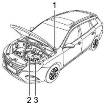
VehicleIdentification
text_image
Technical diagram of a car with numbered parts for identificationI VehicleIdentificationNumber(VIN)
2DriveMotorNumber
3ElectricDriveT transmissionNumber
AlwaysquotetheVehicleIdentificationNumber(VIN) when communicating with MGAuthorised Repairer. If the drivemotororelectric drivetransmission is involved, it
mayberequiredtoprovidetheidentificationnumbersof theseassemblies.
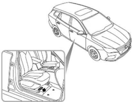
VehicleIdentificationLocation VehicleIdentificationNumber(VIN)
natural_image
Line drawing of a car interior showing the exterior and side view of the seat (no text or symbols)•Onthefloorunderthedriver'sseat;
•Ontheidentificationplate;
- Stampedonaplatevisiblethroughthebottomlefthand cornerofthewindscreen;
PREFACE
- Ontheinnersideofthetailgatevisiblebyopeningthe tailgate.
Note: The DLC is located in the driver footwell at the base of the fasci panel on the RH side. The VIN information can be extracted from the vehicle using the approved diagnostice equipment.
DriveMotorNumber
Stampedonthelowerpartofthedrivemotorhousing.
ElectricDriveTransmissionNumber
Stampedontheupperpartoftheelectricdrive transmissionhousing.
VehicleIdentificationLabel
The VehicleIdentificationLabelcontainsthefollowing information:
•T ypeApprovalNumber
•VehicleIdentificationNumber(VIN)
•GrossVehicleWeight
•GrossT rainWeight
•MaxFrontAxleWeight
•MaxRearAxleWeight
•Model
- EngineType
- DateofProduction
•Country
PREFACE
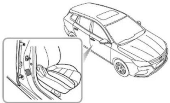
LocationofVehicleIdentificationLabel
TheVehicleIdentificationLabelislocatedatthelowerside ofpassengersideBpillar.
natural_image
Line drawing of a car showing side panel and seat assembly (no text or symbols)InstructionsforUseofElectricVehicle
EffectsofAmbientT emperature
The working performance of the high-voltage battery pack fitted to your vehicle is related to the ambient temperature, this battery power the vehicle power system and therefore it is recommended that where possible the vehicles should be used within the temperature range of 15 to 45°C. This will ensure that the vehicle is at the optimum working state, and help extend the service life of high-voltage battery pack. Extremely higher low temperatures will affect the performance of high-voltage battery pack and vehicle.
InstructionsforHighVoltageBatteryPack Recycling
The high-voltage battery pack fitted to your vehicle contains several lithium-based battery cells, it is installed central motor-vehicle auxiliary disposalmay cause pollution, hazard and damage to the environment. The high-voltage battery pack must be recycled by an MGA authorised repairer or a professional
approveddismantlingagent.Pleaserefertothefollowing informationandrequirements.
ONLYqualifiedpersonnelshouldworkwiththehigh voltagesystemtherisdangerofDEA TH.
Highvoltagesafety:thehighvoltagesystemfittedto yourvehiclefeaturesaHVbatterycontaininghigh voltagecomponentssuchaslithiumbatterypacks andhighvoltagewiringharness;DONOTattempt todismantleanyareaofthissystem,suitablytrained professionalshipobserverisulation safety protectionbeforeworkingonornearthehighvoltage system.
Transportation high-voltage attack classed as a Category 9 hazardous material and must be transported by vehicles qualified in transporting Category 9 hazardous materials.
StorageAllHVcomponents(includingbatteries) shouldbestoredatroomtemperatureandinadry environment. They must be kept away from dangerous sources, such as flammable objects, heat and water sources.
PREFACE
- Internal composition: The high-voltage battery pack consist of lithium batteries (pack), PCB, HV and normal electric wiring, metal casing and other components. It is strongly recommended that the used high-voltage battery pack generated from vehicle scrappage or any other reasons should be disposed of by an MGA authorised Repairer. See official Website for details: www.mg.co.uk.
Note: Instructions: If you decide no to set the recommended MGA authorised Repair to dispose of your high voltage battery, the responsibility of the consequences of environmental pollution or accidents must be bourne by the owner.
DrivingRange
The driving range of your vehicle depends on the HV battery condition, quantity of available electricity, vehicle age (current remaining battery life), weather, temperature, road conditions and driving habit etc.
Therangecanbeaffectedbyotherelectricloads(suchas A/C, lightsetc), drivingstyleandgeneralroadconditions.
Itshouldbenotedthat:
• Thedrivingrangeisrelatedtorateofdischarge. In ordertoavoidahighrateofdischargefromaffecting theperformanceofthehigh-voltagebatterypack, it is recommended that the vehicle is connected to asuitable charger upon illumination of the low battery warning lamp in the instrument pack.
• The actual driving range of vehicle will reduce with the increase of vehicle age.
•TheuseofA/Cwillreducethedrivingrange.
• Thedrivingrangevariesatdifferentspeeds.
- Atlowtemperatures, the driving rangewill bereduced duetotemperature characteristics of the battery during use.
somistance:trentemperatureand lowbatteryvoltage,youmayexperienceinsufficient accelerationorpowerreduction,thisisduetobattery characteristics.
To help increase the range of the vehicle please observe the following:
- Havethevehicleregularlymaintainedasperservice schedule.
•Alwaysensurethetyrepressuresarecorrect.
•T ryandusethevehiclebetweentherecommended ambienttemperatures.
- Donotparkorstorethevehicleforlongperiodswith alowstateofcharge,wherepossiblechargethevehicle as soonaspossiblepriortostorage.
- Removeunnecessaryarticlestoreducethevehicleload.
- UseofhighpowerconsumingsystemssuchasA/Cand heatingwilluselargeamountsofpower, thiswillreduce thedrivingrange.
- Atahighspeed, where possible, closetehindowsto reduce wind resistance and power consumption.
- T rytomaintainasteadyspeedatalltimes, avoid constantaccelerationandbraking.
- Duringacceleration,applytheacceleratorpedalas gentlyaspossible.
- During deceleration, releasethe accelerator pedal; under certain conditions when not applying the brake orgently applying the brake, the energy regeneration system (KERS) will assist in charging the HV battery and extend the driving range.
EqualisationCharging
Inordertoassistinextendingtheservicelifeofthehigh voltagebatterypackisrecommendedthatanequalisation chargeiscarriedoutatregularintervals.
Pleaseesee"EqualisationCharging"inthe"Starting&Driving"section.
PREFACE
HighVoltageSystem

•Thehighvoltagesystemusedonyour vehiclefeaturesACandDCvoltagesupto 410V.Allhighvoltagecomponentshave warninglabelsattached-pleaseobserve these warningsandanyrequirements whenoperatingwithinorclosetothese areas.
•ONLYqualifiedpersonnelshouldworkon, orwith,thehighvoltagesystem-thereis dangerofDEA TH.
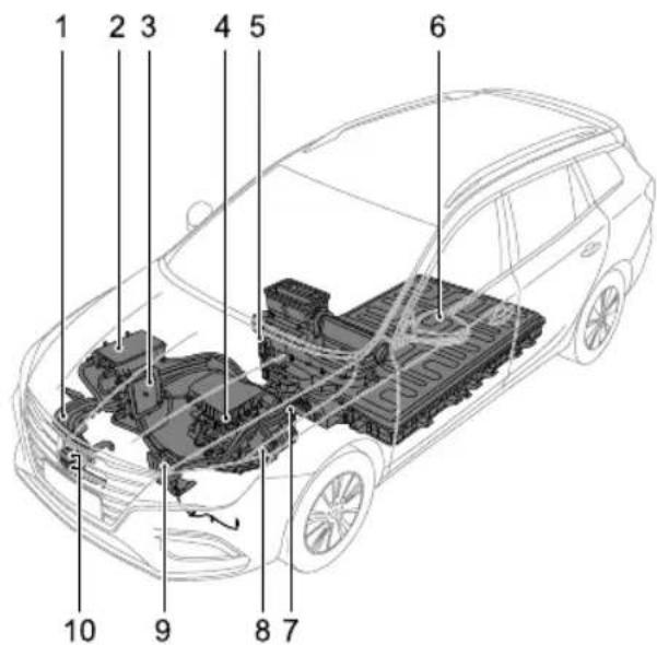
The highvoltagesystemcomponentlayoutis shown below:
text_image
1 2 3 4 5 6 10 9 8 7I HighVoltageHarness
2CombinedChargingUnit (CCU)
3PowerDistributionUnit (PDU)
4ElectricDriveTransmission
5ElectricHeater
6HighVoltageBattery(ESS)
7ManuaServiceDisconnect (MSD)
8ElectricA/CCompressor
9HVBatteryHeater
10ChargingPort
PREFACE
PrecautionsintheEventofanAccident

- EnsurethevehicleisinP , theparkingbrakeisappliedandthevehiclepowersystemisOFF .
•Ifanycablesonthevehicleareexposed,inordertopreventelectricshockorevendeathDONOT makeanycontactwithanycable.
•Ifthevehiclecatchesfire,andthefireissmallandslow,acarbondioxideextinguishercanbeusedto extinguishthefire,andcontactthefireservicesassoonaspossible;ifthefireislargeandspreading quickly,immediatelyevacuatethevehicleandcontactthefireservicesimmediately.
• If the vehicle is involved in a collision and cannot be started, the Manual Service Disconnect(MSD) MUST be disconnected prior to rescue. - When the vehicle is completely or partially immersed in water, switch off the vehicle powers system and evacuate the car immediately. The Manual Service Disconnect (MSD) MUST be disconnected prior to rescue or as soon as the vehicle is reflected or removed from the water. Observethewater/vehicle for any abnormalities such as excessive bubbles or noises, this may indicate battery short circuit issues, if no signs are evident there should not be a shock risk from the body work and recovery can commence.
- If your car is being recovered by an independent recovery agent, please contact MGA authorised Repairer forguidance.
•Thevehicleissuppliedwithanemergencyresponseinformationcard(intheglovebox).Pleaseshow thecardtotherescuepersonnelwhentheyarrive.
InstrumentsandControls
14InstrumentsandControls
16 InstrumentPack
17MessageCentre
27WarningLightsandIndicators
35LightsandSwitches
40 WipersandWashers
44SteeringSystem
46Horn
47 Mirrors
51 Sunvisor
52 Windows
55InteriorLight
56 PowerSocket
58 StorageDevices
61 CupHolder
62RoofLuggageRack
INSTRUMENTSANDCONTROLS
InstrumentsandControls
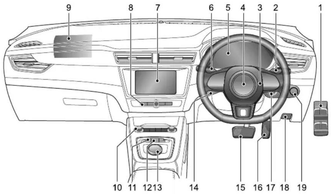
text_image
1 2 3 4 5 6 7 8 9 10 11 12 13 14 15 16 17 18 19INSTRUMENTSANDCONTROLS
PowerWindowSwitch12EnergyRegeneration(KERS)SelectionSwitch
2WiperStalkSwitch | 3ShiftControlKnob
3 HornButton
4DriverAirbag
5 InstrumentPack
6DirectionIndicator/MainBeamStalkSwitch
7 OnboardEntertainmentSystem18
8EntertainmentControls I 9START/STOPSwitch
9FrontPassengerAirbag
10AirConditioningControls
II DrivingModeSelectionSwitch
14 CruiseControlStalkSwitch
15 BrakePedal
16AcceleratorPedal
17 HeadlampLevellingandMirrorAdjustmentSwitch BonnetReleaseHandle
INSTRUMENTSANDCONTROLS
InstrumentPack
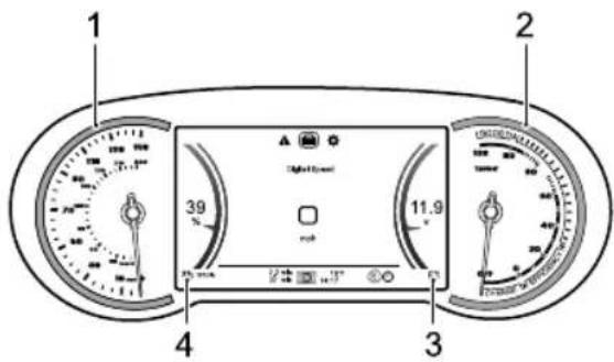
text_image
1 2 3 4 5 6 7 8 9 10 11.9 Digital Range Control PanelSpeedometer(I)
Indicate the vehicles speed in mph and km/h.
PowerMeter(2)
Indicate the power status of the power drives system as a percentage. The blue CHARGE segment indicates that the power drives system is converting part of the kinetic energy into electric energy; the green EFFICIENCY segment indicates that the vehicle is running using an economic
poweroutput;theyellowBOOSTsegmentindicates that thevehicleisrunningusingahighpoweroutput.
ElectricityMeterofLow-voltageBattery(3)
Displaysthevoltageoflow-voltagebattery.
ElectricityMeterofHigh-voltageBatteryPack and RangetoEmpty(4)
Display the current level of high voltage battery charge as a percentage and theremaining range of the vehicle before the high voltage battery becomes flat.
The high-voltage battery pack low battery warning lamp will illuminate when the high voltage battery charge is low. If the voltage continues to drop, this lamp will flash.
IMPORTANT
Whether high tag battery indicator displays alow charge condition, connect to charger and charge immediately.
• Before undertaking any journeys please ensure the high voltage battery contains enough power.
INSTRUMENTSANDCONTROLS
MessageCentre
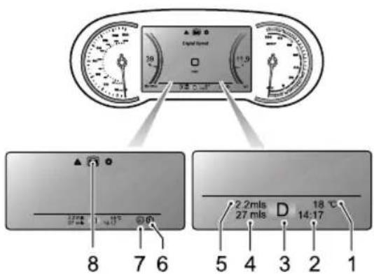
text_image
Digital Speed 8 1.54 17 6 2.2ms 27 mls D 18 °C 5 4 3 2 1 27 ms 14:17Themessagecentreprovidesthefollowinginformation:
IT emperature
2DigitalClock
3GearDisplay
4Odometer
5AccumulativeTripMeter
6EnergyRegenerationLevel
7DrivingMode
8VehicleInformationDisplay
T emperature
Displaysthecurrentambienttemperature.
DigitalClock
Displaysthecurrenttime.
GearDisplay
Displaysthecurrentgearposition(P, R, N, D).
If EP is displayed, it indicates a serious functional failure with the gear shift system in this case, please contact an MGA authorised Repairer immediately.
Odometer
Displaysthetotaldistancethecarhastravelled.
INSTRUMENTSANDCONTROLS
AccumulativeT ripMeter
Displaysthetripdistancesincerereset.
EnergyRegenerationLevel
Displaysthecurrentenergyregenerationlevelofthe vehicle.Formoreinformation,pleasereferto"Energy Regeneration(KERS)"in"Starting&Driving"section.
DrivingMode
Display the current driving mode of the vehicle. Form more information, pleasereferto "Driving Mode (MODE)" in "Starting & Driving" section.
VehicleInformationDisplay
WiththeST ART/STOPSwitchintheON/READYposition, thevehicleinformationdisplayfunctioncanbeselectedas follows:
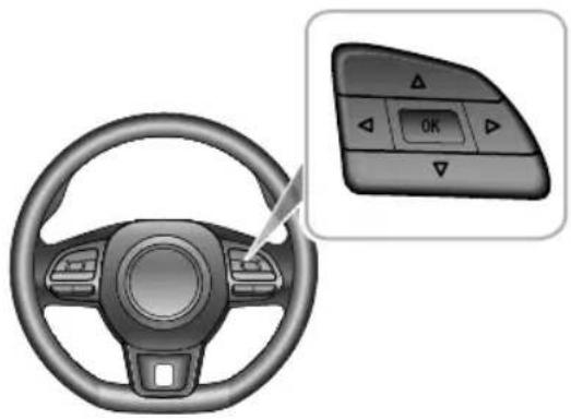
natural_image
Interior view of a car steering wheel with a control panel showing OK button (no text or symbols on the dashboard)- PresstheUP/DOWN/LEFT/RIGHTbuttonintheRH steeringwheelmultifunctionswitchpack,thiswill accessanddisplaythegeneralinformationoptions.
- PresstheUP/DOWNbuttonintheRHsteeringwheel multifunctionswitchpacktoscrollthroughtheoptions.
- PresstheOKbuttonintheRHsteeringwheel multifunctionswitchpacktoconfirmyouroption selectionorlongpresstheOKbuttontoreset.
INSTRUMENTSANDCONTROLS
text_image
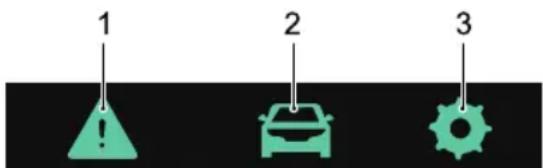
1 2 3The vehicle information display contains the following information:
I WarningInformation
2T ripComputer
3Setting
WarningInformation
Displaysanywarninginformationorimportantnotesthat arecurrentlyrelevanttothevehicle.
TripComputer
Thetripcomputerfunctioncontainsthefollowing:
•EnergyFlow
•DigitalSpeed:displaysthecurrentvehiclespeed.
- CurrentJourney: displaystherange, duration, average speed and average power consumption since startup. It can be reset by long pressing the "OK" button in the RH steering wheel multifunction switchpack.
•Accumulated Total:displaystheranguration, average speed and overpower consumption since the last reset. It can be reset by long pressing the "OK" button or steering wheel multifunction switch pack.
- ElectricInformation:displaytheurrentoperation stateofthevehicleincludingthevoltage,currentand motorspeed.
- TPMSMonitor: Display the current trepressures and temperatures.
INSTRUMENTSANDCONTROLS
EnergyFlow
Theenergyflowinterfaceautomaticallyswitchesbetween displaygraphicstodepictthecurrentdrivestate.The displayrevertstothedefaultscreenthatdisplaysnopower flowwhenthevehiclepowersystemisswitchedtothe READYstate.Othermodesareasfollows.
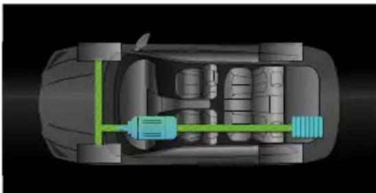
EnergyRegenerationMode
Themotorrecycleskineticenergytochargethe high-voltagebatterypack.
natural_image
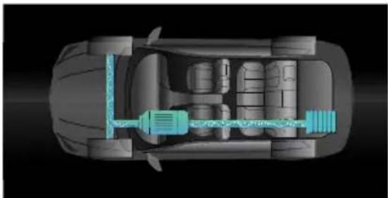
Top-down schematic of a car showing internal battery and transmission line (no text or symbols)ElectricDriveMode
Thevehicleisdrivenbymotor.
natural_image
Top-down technical illustration of a car's internal components, showing engine, battery, and transmission lines (no text or labels)Setting
LuminanceLevel
Displaysthecurrentlevelandallowsadjustmentofthe backlightbrightness.
OverSpeedThreshold
Allowsthesettingoftheover-speedalarmthreshold, pleasenote,theover-speedalarmfunctionisturnedoff when"OFF"isdisplayed.
INSTRUMENTSANDCONTROLS
WarningMessage
Warningmessagesandpromptsaredisplayedinthe informationmessagecentreintheinstrumentpack.Any communicationsaredisplayedin'popup'messages,these canbedividedintothefollowingcategories:
•OperationInstruction
•SystemStateInstruction
•SystemMalfunctionAlert
Please follow the instructions displayed in the 'popup' message or in the case of awarning message, pleaserefer to therelevant section of the owners manual to follow the correct instructions.
The following are a selection of warning message that may appear in the information message centre.
| WarningMessage | Action |
| CruiseControl SystemFail | Indicatesthatthecruisecontrol systemhasdetectedafault.PleasecontactanMGAuthorised Repairerassoonaspossible. |
| IgnitionSystem Fault | Indicatesthatthepowermode hasdetectedafault.Please contactanMGAuthorised Repairerimmediately. |
| StartStopButton Fail | IndicatesthattheSTART/STOP Switchhasdetectedafault.PleasecontactanMGAuthorised Repairerimmediately. |
| PassiveEntryFault | Indicatesthatthepassivekeyless entryfunctionhasdetectedafault.PleasecontactanMG AuthorisedRepairerassoonas possible. |
INSTRUMENTSANDCONTROLS
| WarningMessage | Action |
| ABSFail | Indicatesthattheanti-lockbrake system(ABS)hasdetectedafault. andtheABSfunctionisabout tobedisabled.Pleasecontact anMGAuthorisedRepairer immediately. |
| BrakeFail | Indicatesthatafaulthas beendetectedwithinthe brakingsystem,suchasbrake fluidlow/lossorElectronic Brake-forcedistributionfailure hasoccurred,stopthevehicleas soonassafetypermitsswitchthe vehiclepowersystemOFF ,check thebrakefluidlevelandcontact anMGAuthorisedRepairer immediately. |
| WarningMessage | Action |
| StabilityControl SystemFail | Indicatesthatthedynamic stabilitycontrolsystem(SCS)has detectedafault.PleasecontactanMGAuthorisedRepairerimmediately. |
| TractionControl SystemFail | Indicatesthatthetractioncontrol system(TCS)hasdetectedafault.PleasecontactanMGAuthorised Repairerimmediately. |
| ParkBrakeForce NotEnough | Indicatesthattheelectronic parkingbrakesystemhas detectedafaultwhenparking.PleasecontactanMGAuthorised Repairerassoonaspossible. |
| AutoholdFail | Indicatesthattheautohold functionhasdetectedafault.PleasecontactanMGAuthorised Repairerassoonaspossible. |
INSTRUMENTSANDCONTROLS
| WarningMessage | Action |
| EPSPerformance Decrease | Indicatesthattheelectric powersteeringsystem(EPS) hasageneralfailureandthe performanceisreduced.As soonasconditionspermit,safely stopthevehicleandswitchthe vehiclepowersystemtothe OFFposition.Afterashort while,switchthevehiclepower systemtotheREADYposition, drivethevehicleashortdistance andmonitortheoperationof thesteering,ifthemessageis stilldisplaydorthesteering assistancereducedpleasecontact anMGAuthorisedRepairer immediately. |
| WarningMessage | Action |
| PowerSteering SystemFault | Indicatesthattheelectricpower steeringsystem(EPS)hasfailed.PleasecontactanMGAuthorised Repairerimmediately. |
| SteeringAngle SensorFault | Indicatesthatthesteeringangle sensorhasfailed.Pleasecontact anMGAuthorisedRepaireras soonaspossible. |
| SASUncalibrated SeeHandbook | Indicatesthatthesteeringangle sensorisnotcalibrated.Please contactanMGAuthorised Repairerassoonaspossible. |
| ESCLFault | IndicatesthattheESCLsystem hasdetectedafault.Stopthecar assoonassafetypermits,shut downtheengineandcontact anMGAuthorisedRepairer immediately. |
INSTRUMENTSANDCONTROLS
| WarningMessage | Action |
| ParkAidSystem Fault | IndicatesthatPDCsystemhas detectedafault.Pleasecontact anMGAuthorisedRepaireras soonaspossible. |
| AirbagFault | IndicatesthattheSDMhas detectedafault.Assoonas conditionspermit,safelystop thevehicleandswitchthe vehiclepowersystemtothe OFFpositionandcontactanMG AuthorisedRepairerimmediately. |
| AirbagLampFail | Indicatesthattheairbaglamp hasfailed.PleasecontactanMG AuthorisedRepairerassoonas possible. |
| WarningMessage | Action |
| T yrePressure MonitoringFail | Indicatesthatthetyrepressure monitoringsystem(TPMS)has detectedafault.PleasecontactanMGAuthorisedRepaireras soonaspossible. |
| FrontLeft/Front Right/Rear Left/RearRight T yreSensor BatteryLow | IndicatesthattheTPMShas detectedasensorhasalow battery.PleasecontactanMG AuthorisedRepairerassoonas possible. |
| PedestrianAlert SystemFault | Indicatesthatthepedestrian alertsystemhasdetectedafault.PleasecontactanMGAuthorised Repairerassoonaspossible. |
| DCDCCharge Fault | IndicatesthattheDC-DC converter(DCDC)hasdetectedafault.PleasecontactanMG AuthorisedRepairerimmediately. |
INSTRUMENTSANDCONTROLS
| WarningMessage | Action |
| 12VBatteryChargingSystemFault | Indicatesthatthe12Vbattery chargingsystemhasdetectedafault.PleasecontactanMG AuthorisedRepairerimmediately. |
| BatteryMaintenanceRequiredRefer toHandbook | PleasecontactanMGAuthorised Repairerimmediately. |
| CheckHVBattery | IndicatesthattheHVbatteryhas detectedafault.Pleasecontact anMGAuthorisedRepairer immediately. |
| Escapefrom thevehicle immediately! | Assoonasconditionspermit, safelystopthevehicle andevacuateallooccupants immediately,andcontactanMG AuthorisedRepairerimmediately. |
| WarningMessage | Action |
| SystemFault | Indicatesthatthepowersystemhasdetectedafault.PleasecontactanMGAuthorisedRepairerassoonaspossible. |
| MotorOverheating | Indicatesthatthemotorhasoverheated.PleasecontactanMGAuthorisedRepairerassoonaspossible. |
| EDUCoolantOverheating | IndicatesthattheEDScoolanthasoverheated.PleasecontactanMGAuthorisedRepaireras soonaspossible. |
| MotorFault | Indicatesthatthedrivemotorhasdetectedafault.Assoonasconditionspermit,safelystopthevehicleandswitchthevehiclepowersystemtotheOFFpositionandcontactanMGAuthorisedRepairerimmediately. |
INSTRUMENTSANDCONTROLS
| WarningMessage | Action |
| eCallSystemFault ConsultHandbook | Indicatestothedriverviaa yellowSOSwarninglampthat theeCallsystemhasdetectedafaultandisnotoperatingwithinitsparameters.TheSOSbutton LEDstatusindicatorflashestwice persecond.Pleasecontactalocal MGAuthorisedRepairerassoon aspossible. |
| eCallSystem FailureConsult Handbook | Indicatestothedriverviaa redSOSwarninglampthatthe eCallsystemhasfailedandis notcapableofsupportinginthe eventofanaccident.TheSOS buttonLEDstatusindicatoris notilluminated.PleasecontactalocalMGAuthorisedRepairer immediately. |
| WarningMessage | Action |
| eCallinProgress | IndicatestothedriverviaagreenSOSwarninglampthatanemergencyservicescalliscurrentlyinprogress.TheSOSbuttonLEDstatusindicatorflashesoncepersecond. |
| AutoeCallDisabledConsultHandbook | IndicatestothedriverviaaredSOSwarninglampthatautomaticeCallserviceisdisabled.PleasecontactalocalMGAuthorisedRepairertoreactivatetheautomaticeCallfunction. |
WarningLightsandIndicators
Somewarninglampsilluminateorflashaccompaniedbya warningtone.Certainwarninglampswillbeaccompanied byamomentarywarningsymbolandtextmessage displayedintheinformationcentreintheinstrumentpack.
MainBeamIndicator-Blue

Thisindicatorilluminateswhentheheadlamp
highbeamisturnedon.
SideLampIndicator-Green

Thisindicatorilluminateswhenthesidelamps
areon.
RearFogLampIndicator-Y ellow

Thisindicatorilluminateswhentherearfog
lampsareon.
DirectionIndicators-Green

Theleftandrightdirectionindicatorlampsare representedbydirectionalarrowsthatarelocatedatthe topoftheinstrumentpack.Whentheturningsignallamp flashes,thedirectionindicatorlamponthecorresponding sidealsoflashes.Ifthehazardwarninglampsareoperated, bothdirectionindicatorlampswillflashtogether.lfeither directionindicatorlampintheinstrumentpackflashes veryrapidly,itindicatesthattheturningsignallightonthe correspondingsidehasfailed.
Note: Failureofasiderepeaterlampwillhaveno effectontheflashfrequencyofdirectionindicator lamp.
AirbagWarning-Red

If this lamp illuminates, it indicates that the
SRSortheseatbelthasfailed.Assoonasconditions permit,safelystopthevehicleandswitchthevehicle powersystemtotheOFFpositionandcontactanMG
INSTRUMENTSANDCONTROLS
Authorisedimmediately.AnSRSorseatbeltfaultmay meanthecomponentsmaynotbedeployedintheevent ofanaccident.
SeatBeltUnfastenedWarningLamp-Red

If this lamp illuminates or flashes, it indicates that theseatbeltforthedriverorfrontpassengerremains unfastened.
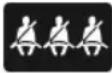
Thisvehicleisequippedwithrearseatbelt warningstoremindyoutoensureanyreseatpassengers havefastenedtheirseatbelts. Thedicatedwarninglamp consistsofthe3sections, I foreachreseatposition, itwillilluminateredoneveryignitioncycleandremain illuminateduntilapre-setspeedisreachedandaftera pre-settmeperiod. Ifall3reseatbeltsarefastened thislampwillextinguishimmediately. Wheneachindividual reseatbeltisfastenedthecolourofthatparticularseat beltwarninglampwillchangefromredtogrey, theother seatpositionswillremainilluminatedred, all3seatbelt
warninglampswillextinguishafterthepre-setspeedis reachedandthepre-settimehasbeensurpassed.
CruiseControlIndicator-Green/Yellow
Ifthecruisecontrolisswitchedon,thesystem willenterintostandbystate,andtheindicatorilluminates in yellow.
Whenthecruise control system operates, this indicator illuminates green, indicating the cruise control system is activated.
Ifafaultinthecruise control system is detected, the indicator will flash in yellow. Please seek an MGA authorised Repairer urgently.
Low-voltageBatteryChargingSystem MalfunctionWarning-Red
Whenthevehiclepowersystemisswitched totheONpositionthislampilluminatesaspartofaself test,whenthesystemisswitchedtoREADYthewarning
INSTRUMENTSANDCONTROLS
lightwillextinguish.Ifthewarninglightilluminateswhilst drivingcontactanMGAuthorisedRepairerattheearliest opportunity.
Ifthebatterypowerislow, thislampilluminatesanda promptmessageappearsintheinformationcentre. In this case, thesystemwillrestrictorturnoffsomeelectrical devices, pleaseensurethevehiclepowersystemisin READYmodetochargethebattery.
StabilityControl/T ractionControlSystem OperationandFaultWarning-Y ellow
If this lamp illuminates, it indicates that the
stabilitycontrolsystem/tractioncontrolsystemhas detectedafault.PleasecontactanMGAuthorised immediately.
If this lamp flashes while driving, it indicates that the system is operating to assist the driver.
StabilityControl/T ractionControlSystemOFF
Warning-Yellow
Ifthestabilitycontrolsystem/tractioncontrol
systemisswitchedoffmanually, this warninglamp will illuminate.
ABSWarning-Y ellow

If this lamp illuminates, it indicates that the ABS
hasdetectedafault.PleasecontactanMGAuthorised immediately.
IfanABSfailureoccurswhiledriving,theABSfunction willbedisabledwhilenormalbrakingwillstillbeavailable. PleasecontactanMGAuthorisedimmediately.
BrakeSystemWarning-Red

Thislampislocatedinthespeedometerface.
If this lamp illuminates, it indicates a fault or issue has
INSTRUMENTSANDCONTROLS
beendetectedinthebrakesystemsuchasbrakefluid lossorelectronicbraking-forcedistributionfailure.Please stopthevehicleassoonassafetypermits,turnoffthe START/STOPSwitch,checkthebrakefluidlevel(referto "BrakeFluidCheckandT opUp"in"Maintenance"section) andcontactanMGAuthorisedimmediately.
BoosterSystemWarning-Y ellow/Red

Thislampislocatedinthemessagecentre.If theboostersystemdetectsafault, thislampilluminates yellow, pleaseslowdown, stopthevehicleassoonas safetypermitsandcontactanMGAuthorisedRepairer immediately.
Iftheboostersystemsuffersaseriousfailure, thislamp illuminatesred, stopthevehicleassoonassafetypermits, turnofftheSTART/STOPSwitchandcontactanMG AuthorisedRepairerimmediately.
ElectricPowerSteering(EPS)/ElectricSteering ColumnLock(ESCL)Warning-Y ellow/Red

Thewarninglampisusedtoindicateelectric tedsteeringfailureorelectronicsteering failure.
If this lamp illuminates yellow, it indicates the electric power assisted steering system has general failure and the performance is reduced. Please stop the car as soon as safety permits. If the lamp still illuminates after restarting the vehicle and driving for short while, please contact an MGA authorised Repairer immediately.
If this lamp illuminates red, it indicates the electric power assisted steering system has a general failure relevant to steering angles sensing. Please contact an MGA authorised repairer as soon as possible.
If this lamp illuminates red and flashes, it indicates the electric power assisted steering system has a severe failure. Please contact an MGA authorised Repairer immediately.
INSTRUMENTSANDCONTROLS
Ifthelampilluminatesyellowandcontinuallyflashes accompaniedwithanaudiblewarning,itindicatesthe electricsteeringcolumnlockhasdetectedafaultor failed.PleasecontactanMGAuthorisedRepaireras soonaspossible.Ifthislampextinguishesafterflashing forawhile,itindicatesthatthesteeringwheelislocked, pleaseattempttorotatethesteeringwheeltoremoveany adverseloads.
T yrePressureMonitoringSystem(TPMS)
Warning-Y ellow

If this warning lamp illuminates it indicates that
atyrepressureislow,pleasecheckthetyrepressures.
If this lamp flashes first and then remains illuminated after a period of time indicate the system has detected a fault. Please contact an MGAuthorised Repairer as soon as possible.
ImmobiliserSystemWarning-Red
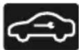
Ifnovalidkeyisdetected, thislampwill
illuminatedPleasestheorredeyoputhe
smartkeyatthebottomofthecentreconsoleupholder.
Forspeciflocationrequirements;eferto"Alternative StartingProcedure"in"Starting&Driving"section.
WiththeST ART/STOPSwitchirtheON/READYposition, ifremotekeybatteryislow, thislampflashes, please replacethebatteryassoonaspossible.
WithSTART/STOBwitchOfPosition the lampflashesifthevehicleisfullyarmedorpartiallyarmed withsecuritysystem.
Electron ParkingBrak(EPB)AutHold
StatusIndicator-Red/Green

If this lamp illuminates red, it indicates the EPB
systemisenabledfthislampilluminatesredandflashes, itindicatesthattheEPBsystemhasfailedPleasecontact anMGAuthorisedassoonaspossible.
INSTRUMENTSANDCONTROLS
Whentheautoholdsystemisoperatingtoassistthedriver, thislampilluminatesgreen.
ElectronicParkingBrake(EPB)System MalfunctionWarning-Yellow

IfanEPBsystemfailureisdetectedorthe
systemisunderdiagnosis, thislampwillilluminate. Please contactanMGAuthorisedassoonaspossible.
READYIndicator-Green

Thislampisusedtoindicatethatthevehicleis
readyfordriving.
ChargingStatusIndicator-Yellow

Thislampwillilluminatewhenthevehicleis
connectedtoachargepoint,itwillremainonduring chargingandextinguishafterchargingiscompleted.
ChargingConnectionIndicator-Red

Thislampwillilluminatewhenthevehicleis
connectedtoachargepoint.
PowerSystemMalfunctionWarning-Red
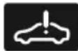
temperatureistoohigh.PleasecontactanMGAuthorised as soon as possible.
MotorMalfunctionWarning-Red
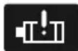
Ifafaultorfailureisdetectedinthemotoror
thepowerelectronicboxofelectricdrivesystem,thislamp
willilluminate.Pleasestopthevehicleassoonassafety permits,turnofftheSTART/STOPSwitchandcontactan MGAuthorisedimmediately.
High-voltageBatteryPackLowBattery
Warning-Y ellow

Thislampwillilluminatewhenthehighvoltage batterychargeislow,ifthevoltagecontinuestodrop,this lampwillflash.Wherepossiblepleasechargethehigh voltagebatterybeforethislampenterstheflashingstage.
High-voltageBatteryPackDisconnection
Warning-Y ellow

Whenthehigh-voltagebatterypackis connected, this lamp will not illuminate. This lamp will only illuminate when the high voltage battery is disconnected or isolated.
High-voltageBatteryPackMalfunctionWarning
Red

Thislampwillilluminateifafaultisdetected orthehighvoltagebatteryfails.PleasecontactanMG AuthorisedRepairerimmediately.
Thislampwillflashifthehighvoltagebatterytemperature istoohigh.Pleasestopthecarassoonassafetypermits, switchthevehiclepowersystemtotheOFFposition,and leavethevehicleimmediately.ContactanMGAuthorised Repairerattheearliestopportunity.
High-voltage battery pack relay, desiosfailuris recorded, lamjas Resascontact MG Authorised Repairerassoonaspossible.
DrivingPowerLimitedWarning-Y ellow

This lamp will illuminate the vehicle power has
beenreduced.
INSTRUMENTSANDCONTROLS
eCallSOSIndicator-Red/Y ellow/Green

If the system is ready and an emergency services
call(eCall)isinprogress,theindicatorilluminatesgreen.
Ifthesystemisstillcapableofsendingoutvehicle informationmessagetothecallcentre,butothereCall capabilitiesarelimitedduetoafaultinthesystem,the indicatorwillilluminateyellow.IftheeCallsystemhas failedandnotoperational,theindicatorilluminatesred. Iftheyelloworredindicatorisilluminatedpermanently aftersystemself-test,pleasecontactanMGAuthorised Repairerimmediately.
SystemFaultMessagesIndicator-Yellow/Red

Thisindicatorisusedtoalertthedriverofa
storedwarning,itisinyellowforgeneralfailuresandin redforseriousfailures.Pleasereferto"MessageCentre" inthissectionforthesefailures.
INSTRUMENTSANDCONTROLS
LightsandSwitches
MasterLightSwitch
text_image
3 2 1 R D X G 4 AUX 5 B C A A A A A A A A A A A A A A A A A A A A A A A A A A AIAUTOLamp
2SideLampandSwitchIllumination
3DippedHeadlamps
4LampsOff
AUTOLamp
WhentheSTART/STOPSwitchisintheACCposition,the autolightingsystemdefaultstotheONposition(1).The AUTOlightingsystemwillautomaticallyswitchtheside lampsandswitchilluminationonandoffaccordingtothe intensityofcurrentambientlight.
WiththeSTART/STOPSwitchintheON/READ Yposition, theAUTOlightingsystemwillautomaticallyswitchtheside lamps, switchilluminationanddippedbeamheadlampson andoffaccordingtotheintensityofcurrentambientlight.
Note: This function uses alightsensor that monitors exterior ambient light levels. Forsomodels, the sensor is fitted in the centre of the fasci panel near the windscreen. DONOT mask cover this area. Failure toadheret this may result in headlampson when not necessary.
SideLamp/SwitchIllumination
Rotatethemasterlightswitchtoposition2toswitch onthesidelampsandswitchillumination.Withthe START/STOPSwitchintheOFFposition,ifthesidelamps
INSTRUMENTSANDCONTROLS
stayonwhenthedriver'sdoorisopened,anaudiblealarm willsound.
Headlamps
When the START/STOP switch is in the ON/READY position, rotatethemaster light switch to position 3 to switch on the dipped beam head lamps and sidelamps.
LampsOff
Rotatethemasterlightswitchtoposition4toswitchchoff thelamps.Releasingtheswitchwillallowittoreturnto theAUTOswitchposition
FollowMeHome
AftertheSTART/STOPSwitchisturnedoff,pullthelight levertowardsthesteeringwheel.Thiswillenablethe FollowMeHomefunction,dippedbeamheadlampsand sidelampswillilluminatedependinguponthevehicle configuration.Forsomemodels,itcanbesetinthe "ComfortandConvenience"in"Vehicle"settingsonthe entertainmentdisplay.
DaytimeRunningLamps
Thedaytimerunninglampsilluminateautomaticallywhen theSTART/STOPSwitchisintheON/READ Yposition.
FindMyCar
Afterthevehiclehasbeenleftinalockedconditionin excessof2minutes,pressingthelockbuttonagainonthe remotekeywillenabletheFindMyCarfunction.This functionwillidentifythecarbymeansofanaudibleand visualalert.PressingtheLockbuttononthehandsetagain willsuspendthisoperation.PressingtheUnlockbutton willcancelthisoperation.
INSTRUMENTSANDCONTROLS
HeadlampLevelingManualAdjustment
text_image
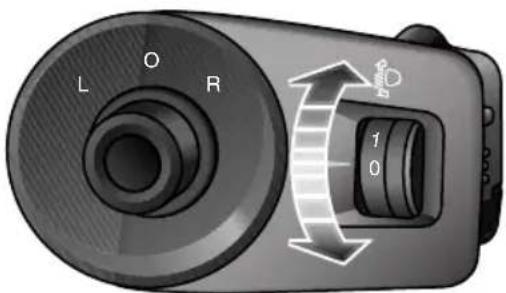
L O R 1 0Position0istheinitialpositionoftheheadlamplevelling adjustmentswitch. Theheadlamplevelingcanbeadjusted asperthefollowingtableaccordingtothevehicleload.
| Location | Load |
| 0Driver,ordriver&frontpassenger | |
| 1 | Alltheseatsoccupiedwithnoloadinthe bootspace |
| 2 | Alltheseatsoccupiedplusanevenly distributedloadinthebootspace |
| 3 | Driveronly,plusanevenlydistributedload inthebootspace |
INSTRUMENTSANDCONTROLS
DirectionIndicator/MainBeamSwitch

T akecarenottodazzleoncomingvehicles whendrivingusingmainbeamheadlamps.
text_image
Diagram showing a car steering wheel with numbered components and a close-up of the steering wheel's head view.DirectionIndicators
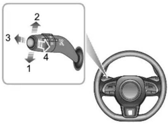
MovethelightstalkswitchdowntoindicateaLEFTturn (1). MovethelightstalkswitchuptoindicateaRIGHT turn(2). The corresponding GREENdirectionindicatorin
theinstrumentpackwillflashwhentheturnsignallamps areworking.
Rotating thesteeringwheelwillcancel theindicator operation(smallmovementsofthesteeringwheelmay notoperatetheselfcancelling). T oindicatealanechange, movetheleverbrieflyandrelease,theindicatorswillflash threetimesandthencancel.
Main/DippedBeamHeadlampsSwitching
WiththeST ART/STOPSwitchintheON/READ Yposition andtheheadlampson, pushthelightstalkswitchtowards theinstrumentpanel(3)toturnonmainbeams. At this time, themainbeamindicatorintheinstrumentpackwill illuminateandthemessagecentrewillprompt"MainBeam On". Pushthelightstalkswitch(3)onceagaintoswitchto dippedbeams.
MainBeamFlash
T obrieflyflashthemainbeamonandoff, pullthelever towardsthesteeringwheel(4) and then release.
INSTRUMENTSANDCONTROLS
RearFogLamps

Foglightsshouldonlybeusedwhenvisibility isbelow100m-otherroaduserscouldbe dazzledinclearconditions.
text_image
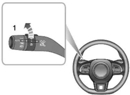
1 2 3 4 5 6 7 8 9 10 11 12 13 14 15 16 17 18 19 20 21 22 23 24 25 26 27 28 29 30 31 32 33 34 35 36 37 38 39 40 41 42 43 44 45 46 47 48 49 50 51 52 53 54 55 56 57 58 59 60 61 62 63 64 65 66 67 68 69 70 71 72 73 74 75 76 77 78 79 80WiththeSTART/STOPSwitchintheON/READYposition andtheheadlampson,rotatetheoglampswitchto position I toturnontherearfoglamps.Therearfoglamp
indicatorilluminatesintheinstrumentpackwhentherear foglampsareon.
Note: Therearfoglampswillturnoffautomatically whenthemasterlightswitchisswitchedoff.
HazardWarningLamps
Pressthehazardwarninglampbuttontoturnonthe hazardwarninglamps.Atthistime,allturnsignallamps anddirectionindicatorswillflashtogether.Pressthe buttonagaintoturnoffthehazardwarninglamps.All turnsignallampsanddirectionindicatorswillstopflashing. Formoredetailsandlocationreferto'HazardWarning Devices'under'EmergencyInformation'.
INSTRUMENTSANDCONTROLS
WipersandWashers
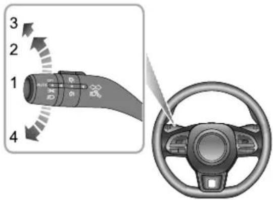
FrontWindscreenWiperOperation
text_image
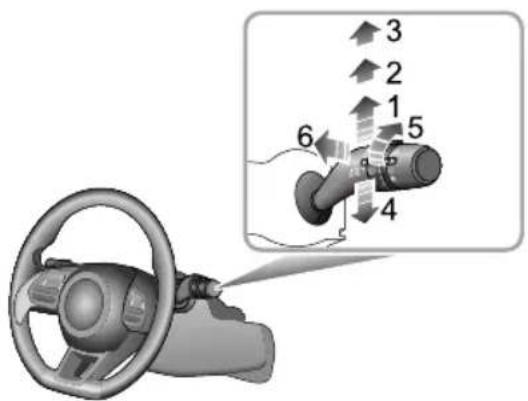
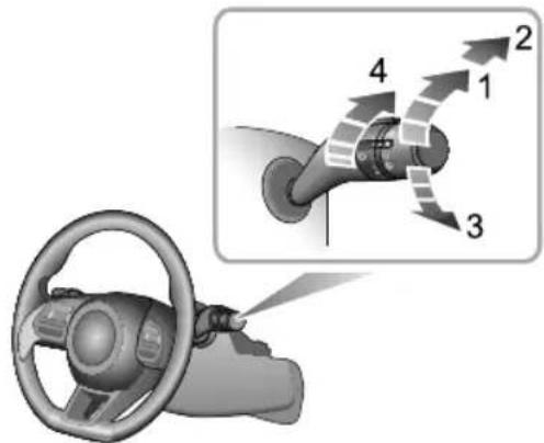
Diagram showing car steering wheel and hand valve with numbered directional arrows indicating motion or movement.Thefrontwipersandwasherswillonlyoperatewhen theSTART/STOPSwitchisintheON/READYposition. Operatethestalkswitchtoselectdifferentwipingmodes: Intermittentwipe(1) Slowwipe(2)
- Fastwipe(3)
•Singlewipe(4)
•Automaticwipeintervaladjustment * /Rainsensor sensitivityadjustment *(5)
•Programmedwipe(6)
IntermittentWipe
BypushingtheleveruptothelIntermittentwipeposition (1), thewiperswilloperateautomatically. T urntheswitch (5) * toadjusttheintermittentwipefrequency. Thisspeed will also changewith the vehiclespeed. Asthevehicle speed increases, thewiperfrequency increases. Asthe vehiclespeed decreases, thewiperfrequency decreases.
Somemodelsareequippedwitharainsensorfitted totheinteriorrearviewmirrorbasetodetectvarying amountsofwaterontheoutsideofthewindscreen.With Intermittent/Automaticselected,thevehiclewilladjust thewipingspeedaccordingtothesignalsprovidedbyrain sensor.T urntheswitch(5) * toadjustthesensitivity of rainsensor.Asthesensitivityincreases,thewipinginterval decreases.
INSTRUMENTSANDCONTROLS
Note: Immediately operating the wiperonetime can be achieved by increasing the sensitivity of frainsensor. If therainsensor detects continuous rainwater, the wiperwill keep working. Whennorain is detected, it is recommended to switch automatic wipe.
SlowWipe
Bypushingtheleveruptotheslowspeedwipingposition
(2), thewiperswilloperateslowly
FastWipe
Bypushingtheleveruptothefastspeedwipingposition
(3), thewiperswilloperateatfastspeed.
SingleWipe
Pressingthelever(4)downandreleasingwilloperate asinglewipe,iftheleverishelddown,thewiperswill operateathighspeeduntiltheleverisreleased.
Note: Whenthevehicleisstationary, if the bonnet is opened, the frontwiper/washer will stop working immediately.
IMPORTANT
- Avoidoperatingthewipersonadrywindscreen.
- Infreezingorextremelyhotconditions,makesure thatthewiperbladesarenotfrozenoradheredto thewindscreen.
• Inwinter, removesnoworicefromaroundthearms andblades, includingthewipedareaofthescreen beforeuse.
ProgrammedWipe
Pullthestalkswitchtowardthesteeringwheel(6),the windscreenwasherswilloperateimmediately.After ashortdelay,thewiperswillcommenceoperatingin conjunctionwiththewashers.
Not the wipers continue operating for further three wipes after the stalk switch is released after severalseconds, there will be further wiping to remove any washer fluid from the screen.
INSTRUMENTSANDCONTROLS
IMPORTANT
Ifthewashersfaltodeliverthewindscreenwasher fluid, releasethestalkswitchimmediately. This will preventthewipersfromoperating,andtheconsequent riskofvisibilitybeingimpairedbydirtsmearingacross theunwashedwindscreen.
RearWindscreenWiperOperation
text_image
Diagram showing a car steering wheel and its directional flow path with numbered arrows indicating motion or movement.Therearwiperandwasherwillonlyoperatewhenthe START/STOPSwitchisintheON/READYposition.Rotate therearwindowwiperswitchtoyourdesiredselection:
- Intermittentwiping(I)
•Wipeandwash(2)
•Wipeandwash(3)
•Wiperintervaladjustment(4)
INSTRUMENTSANDCONTROLS
Intermittentwipe
Rotatetherarwindowwiperswitchtointermittentwipe (1),therearwindowwiperwilloperate,afterseveral consecutivewipes,thewiperswillenterintointermittent mode. Thetimeperiodbetweenthewipscanbe increased/decreasedviatheintermittentwipefrequency adjustmentswitch(4).
Washandwipe
T urntherearwindowwiperswitchtothewashandwipe (2)positionandhold,therearwindowwiperandwasher willoperate,therearwindowwiperwipesquickly.release theswitchallowingittoreturntointermittentwipe(1), therearwindowwasherwillstopoperating,andthewiper wipesslowly,changethestalkswitchposition4toadjust thewipespeed.T urntherearwindowwiperswitchto washandwipe(3)andhold,therearwindowwiperand washerwilloperate.releasetheswitchallowingitto returntotheOFFposition,therearwindowwasherwill stopoperating,andtherearwindowwiperwipesfor3 times,afterseveralseconds,thewiperwillwipeoncemore toremovethewasherfluidontherearscreen.
Note: Whenthetailgate is opened dearwiper operations will be disabled.
Note: Whenthefrontwindscreenwipersareturned on, iftheshiftcontrolknobisturnedtoRposition, the rearwiperwilloperate.
INSTRUMENTSANDCONTROLS
SteeringSystem
AdjustmentofSteeringColumn

DONOTattempttoadjusttheheightor angleofthesteeringcolumnwhilethecaris inmotion. Thisisextremelydangerous.
natural_image
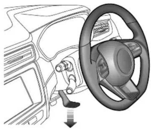
Interior view of a car showing steering wheel and dashboard (no text or symbols)T oadjusttheangleorheightofthesteeringcolumntosuit yourdrivingposture:
I Fullyreleasethelockinglever.
2Holdthesteeringwheelinbothhandsandtiltthe steeringcolumnupordowntomovethewheelinto themostcomfortableposition.
3Pushorpullthesteeringwheeltowardsorawayfrom thebody.
4Oncecomfortabledrivingpositionhasbeenselected, pullthelockingleverfullyuptolockthesteering columnintoitsnewposition.
INSTRUMENTSANDCONTROLS
ElectricPowerSteering

If the electric power steering fails or cannot operate the steering will appear very heavy, this will affect drivings safety.
Theelectricpowersteeringsystemonlyworkswhenthe vehicleisinREADYmode.Thesystemoperatesviaa motorwithassistancelevelsautomaticallyadjustedbased onvehiclespeed,steeringwheeltorqueandsteeringwheel angle.
IMPORTANT
Holdingthesteeringwheelonfulllockforlongperiods willresultinateductioninpowerassistancecausinga heavierfeeltothesteeringforashortperiodoftime.
ElectricPowerSteering(EPS)WarningLamp
Referto"WarningLightsandIndicators"in"Instruments andControls"section.
If the battery has been disconnected for any reason, upon reconnection the warning lamp willilluminate yellow. Movement of the steering wheel from lock to lock will initial is the system and the lamp will be extinguish.
INSTRUMENTSANDCONTROLS
Horn
natural_image
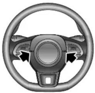
Top-down view of a car steering wheel with three blades and a central hub (no text or symbols)Pressthehornbuttonarea(indicatedbythearrow)onthe steeringwheeltooperatethehorn.
Note: The vehicle horn button and the driver's air bag are located in close proximity on the steering wheel. The illustrations show the position of the horn (indicated by arrow), please ensure that you press
inthisareatoavoidanypotentialconflictwiththe operationoftheairbag.
IMPORTANT
T oavoidpossibleSRSissues, pleasedonotpresswith excessiveforceorhittheairbagcoverwhenoperating thehorn.
INSTRUMENTSANDCONTROLS
Mirrors
DoorMirrors
Note: Objectsviewedindoormirrorsmayappear furtherawaythantheyactuallyare.
ElectricDoorMirrorGlassAdjustment
natural_image
Interior view of a car dashboard with steering wheel and rotary knob (no text or symbols)-
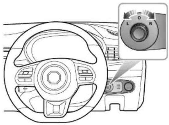
Rotatetheknobtoselectleft(L)orright(R)door mirror.
-
Movetheknobinthedesireddirectiontoadjustthe angleofthedoormirrorglass.
- Upon completion of the adjustment, rotatetheknob back to the central position; this will ensure no accidental adjustment of the mirror.
HeatingElements \*
The doormirror have integral heating elements which disperse ice or mist from the glass. The heating elements operate while the heated Rear Window is switched on.
Note: The heating element so frear window and door mirror will only work when the powers system is in READY mode.
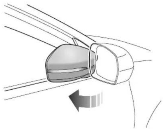
MirrorFolding
Themirrorscanbefoldedbacktowardsthesidewindows intoa'park'positiontoenablethecartonegotiatenarrow openingsandavoidcollisions.
INSTRUMENTSANDCONTROLS
natural_image
Diagram of a car's wheel and dashboard with directional arrow (no text or symbols)ManualFoldingofDoorMirror
Forvehiclesnotfittedwiththeelectricdoormirrorfold option,theexteriormirrorscanonlybefoldedbackwards manually.
ElectricFoldingofDoorMirror
Forvehiclesfittedwithelectricdoormirrorfolding, rotate theknobtothemiddleposition, and pushtheknobdown.
Thedoormirrorswillbefoldedautomatically.Pushing
theknobdownwardsagainwillreturnthemirrorstotheir originalposition.
Note: Electrical folding doormirrorsthath have been moved from their positions by manual or accidental means must be reset by operating the knob to complete fold and deployment on time.
IMPORTANT
- Doormirrorglassadjustmentsareoperatedby electricalmotors. Operatingthemdirectlybyhand maydamagetheinternalcomponents.
- Washingorflushingdoormirrorswithhighpressure waterjetsorcarwashesmayresultinelectrical motorfailure.
INSTRUMENTSANDCONTROLS
InteriorRearviewMirror
Adjustthebodyoftheinteriorrearviewmirrortoachieve thebestpossibleview.Theanti-dazzlefunctionofthe interiorrearviewmirrorhelpstoreduceglarefromthe headlampsoffollowingvehiclesatnight.
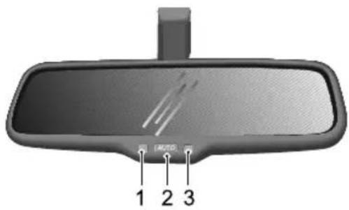
AutomaticAnti-dazzleInteriorMirror \*
text_image
1 2 3I OperationIndicator3LightSensor 2AutomaticAnti-dazzleFunctionSwitch
AfterthecarisplacedinREADYmode,theautomatic anti-dazzlefunctionisswitchedonautomatically(operation indicatorON).Ifthesystemdetectsafollowingvehicle wheretheheadlampsmaydazzlethedriver,thelightsensor switchesontheanti-dazzlefunction.Presstheautomatic anti-dazzlefunctionswitch(operationindicatorOFF)to switchofftheautomaticanti-dazzlefunction,andpressit againtore-startthisfunction.
Theautomaticanti-dazzlefunctionmaybeimpairedor limitedinthefollowingsituations :
Thelightsofthefollowingvehiclearenotdetectedby thelightsensor.
Reservegearisselected.
Not attaching film month rear window may have influence the stage automati anti-dazzle function.
INSTRUMENTSANDCONTROLS
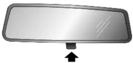
ManualAnti-dazzleInteriorRearviewMirror *
natural_image
Simple diagram of a rectangular mirror with an arrow pointing downward (no text or symbols)Movetheleveratthebaseoftheinteriorrearviewmirror tochangeitsangle,soastoachievetheanti-dazzlefunction. Normalvisibilityisrestoredbypullingtheleverbackagain.
Note: In some circumstances, the view reflected in 'dipped' manual mirror can confuseth driver as to the preciselocation off following vehicles.
INSTRUMENTSANDCONTROLS
Sunvisor

Thevanitymirroronthedriversideshould onlybeusedwhenthevehicleisstationary.
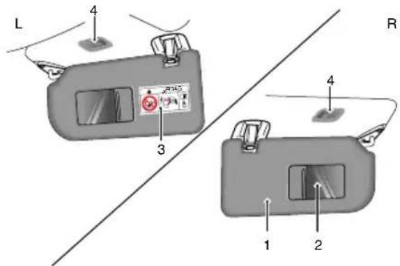
Sunvisor(1)andvanitymirror(2)arearrangedontheroof aheadofboththedriverandthefrontpassenger.Certain modelsarefittedwithvanitymirrorlights(4)depending onthevehicleconfiguration.
text_image
L 4 3 R 1 2 4Pullthesunvisordownwardtousethevanitymirror.If theroofhasvanitymirrorlights,thevanitymirrorlightis switchedonwhenthecoverisopened,anditisswitched offwhenthecoverisclosed.
Note:Warningsandinstructionsontheuseofachildrestraint(3)areattachedtobothsidesofthepassengersunvisor.
NEVERuserearwardfacingchildrestraintsonaseat protectedbyanACTIVEAIRBAGinfrontofit,DEATH orSERIOUSINJURYtotheCHILDcanoccur.
INSTRUMENTSANDCONTROLS
Windows
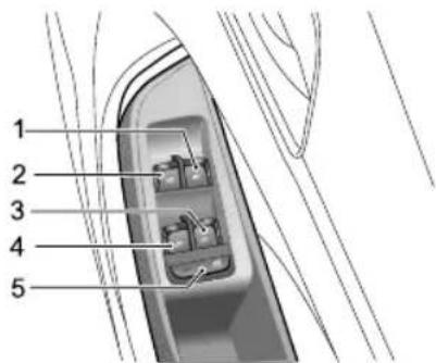
PowerOperatedWindowSwitch
text_image
1 2 3 4 5FrontRightWindowSwitch
2FrontLeftWindowSwitch
3RearRightWindowSwitch
4RearLeftWindowSwitch
5 RearWindowIsolationSwitch
WindowOperation

Ensurechildrenarekeptclearwhenraisingor loweringawindow.

Improperuseoractivationoftheelectric windowsbychildrencouldcauseseriousharm orevendeath.Itistheresponsibilityofthe driverandadultpassengerstoensurethat whencarryingchildrenthenecessarysteps aretakentoisolatethewindowoperation. Thisshouldincludetheremovalofthekey whenchildrenareleftaloneinthevehicle.
Pushtheswitch(1-4)downtolower, andpulltheswitchuptoraisethewindow. Thewindowwillstopmovingassoon astheswitchisreleased(unlessthe'One-T ouch'function isactive).
Note: The front and rear passenger windows can also be operated by individual window switch, mounted on each door. Therear window switches will not operate if therear windowisolations switch has been activated.
INSTRUMENTSANDCONTROLS
Note: The electric windows can be operated with the vehicle powersystem in the ACC, ON and READY positions. (Forsafety: door should be closed).
RearWindowIsolationSwitch
Pressthebutton(5)toisolatetherearwindowcontrols, pressagaintorestorecontrol.
Note: It is recommended that you ISOLATE therear windows switches when carrying a child.
"One-T ouch"Down
Thewindowcontrolswitch(1-4)has2positions.Short presstthewindowcontrolswitchtothe"2"positionand release. Thewindowautomaticallydescendstofullyopen. Windowmovementcanbestoppedatdesiredposition atanytimebyoperatingthecorrespondingswitchduring descent.
"OneT ouch" Upwith "Anti-T rap"
Dependingonvehiclespecification,somewindowsmay havethe"OneTouch"upfunction.Liftingtheswitchtothe
"2"positionforashorttimeandreleasingwillautomatically closetehindowcompleteWindowmovementcan bestoppedatadesiredpositionatanytimebybriefly operatingtheswitchagain.
The "Anti-Trap" functionisasafetyfeaturewhichprevents thewindowfromfullyclosingifanobstructionissensed-ifthishappensthewindowwillopenslightlytoallowthe obstructiontoberemoved.
Note: DONOToperatethepowerwindowcontrols continuouslyseveraltimesinashorttimeframe, otherwisethepowerwindowcontrolsmaybedisabled toprotectthemotor. If this occurs, please wait a few seconds until the motor cools down in the case of the driver's window with "One T ouchand Anti-Trap" please wait 30 seconds prior to operation some cases it may take 30 minutes completely cooldown, during which timethenegative battery lead should not be disconnected.
Note: If the battery is disconnected, the "One-Touch" and "Anti-Trap" features will belost. T orestorethis
INSTRUMENTSANDCONTROLS
feature,fullyopenandthenfullyclosethewindow holdingtheswitchfor5secondsintheclosedposition.
"LazyLock"Function \*
The "LazyLock" function can open or close all the windows by using theremote key from outside the vehicle as long as it is with indetection range.
Pressandholdtheremotekeyunlockbuttonuntilthe windowsstarttoopen, releasetheunlockbutton, all windowswillopenfully. Withthewindowsopen, press andholdtheremotekeylockbuttonuntilthewindows starttoclose, releasethelockbutton, thewindowswill completely close.
INSTRUMENTSANDCONTROLS
InteriorLight
FrontInteriorLamp
text_image
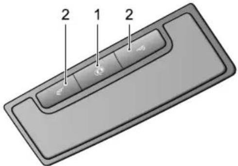
2 1 2ManualOperation
Pressoneoftheswitches2toturnthecorresponding courtesylighton,pressagaintoswitchoff.
AutomaticOperation
Preshewitch(1) tselectrontourteslamp automaticoperation, pressagaintoturnoffthefunction.
Whentheautomaticoperationisenabled,courtesylights willilluminateautomaticallywheneverthefollowingoccur.
•Thecarisunlocked.
•Anydoorisopened.
Note: Undernormal circumstances, if a door or the tailgate is left open for longer than 15 minutes, the courtesylightswillextinguish automatically. In case of low battery, the courtesylightswillextinguish quicker.
INSTRUMENTSANDCONTROLS
PowerSocket
FrontConsolePowerSocket

Pleaseensurethesocketlidisinsertedwhen thepowersocketisnotinuse. Thiswill ensurenodebrisorforeignobjectssenter thesocketpreventingitsuseorcauseshort circuits.
text_image
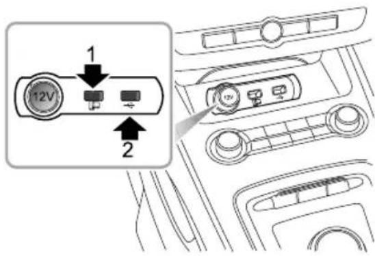
12V 1 2The 12Vfrontconsolepowersocketislocatedinthe storageboxinfrontoftheshiftcontrolknob.When
theSTART/STOPSwitchisintheACCorON/READY positions, itcanbeusedasapowersupply.
Thereare2USBports(1&2)equippedtotherightof the12Vfrontconsolepowersocket.TheUSBportscan providea5Vvoltagewhenservingasapoweroutlet,or realizedatatransmission.USBportIcanalsoprovide 'Vehicle-MobilePhoneInterconnection'function.
Note: The voltage of the front console powers socket is 12 volt, and the power rating is 120 watt. Do not use electrical equipment with the power exceeding the rating.
Note: Duetoconfiguration differences, some of the vehicle's USBports may not support some fast charging devices.
Note: Extended use of the accessory powers socket and USB socket when the vehicle power system is switched off will cause premature discharging of the vehicle battery.
Note:Nocigarettelighterisavailableonthevehicle. Ifrequired,pleaseconsultanMGAuthorisedRepairer.
INSTRUMENTSANDCONTROLS
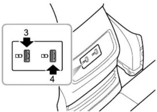
RearConsoleUSBChargingPorts*
text_image
3 4Note: Use of the front console powers socket or USB port when the vehicle is not in READY mode will consume the battery power; extended use will cause premature discharging of the vehicle battery, and the vehicle may thus cannot be switched into READY mode.
Thereare2USBports(3&4)locatedonrearconsole plate,whentheSTART/STOPSwitchisintheACCor ON/READYpositions,theUSBportscanprovide5V voltageservingaspoweroutlets.
Note: Duetoconfiguration differences, some of the vehicle's USB ports may not support some fast charging devices.
INSTRUMENTSANDCONTROLS
StorageDevices
Instructions
- Pleasecloseallstoragedeviceswhenthecarisin motion.Leavingthesstoragedevicesopenmaycause personalinjuryincasesofasuddenstart-off,emergency brakingandacaraccident.
- Donotplaceflammablematerialssuchasliquidor lightersinanystoragedevices. Theheatinhot conditionsmayigniteflammablematerialsandleadto afire.
GloveBox
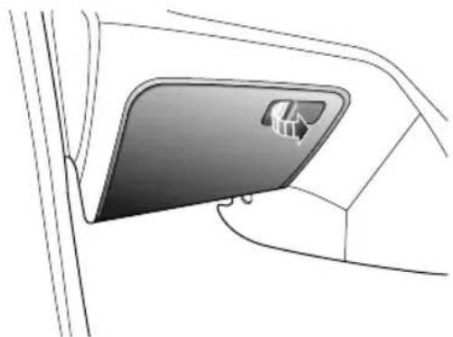
natural_image
Diagram of a car door with a mounted door panel showing a house symbol (no text or labels)T oopentheglovebox, pullthehandleontheglovebox cover(asindicatedbythearrow).
Pushthelidforwardtoclosetheglovebox.Makesurethe gloveboxisfullyclosedwhenthecarisbeingdriven.
INSTRUMENTSANDCONTROLS
CubbyBox
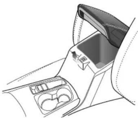
natural_image
Interior view of a car's rearview and dashboard compartment showing intake, vent, and seat (no text or symbols)Liftthearmrest(arrowed)toopenthecompartmentcover. Putthecoverdowntocloseit.
GlassesBox

Theglassesboxshouldonlybeusedwhenthe carisstationary.
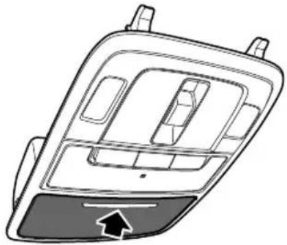
natural_image
Line drawing of a car interior panel with no text or symbolsTheglassesboxislocatedintheproximityofthefront interiorlamps.Pressthepanel(asindicatedbythearrow) toopentheglassesbox.Closetheglassesboxwhenitis notinuse.
Note: Not all glasses will fit insidethe glasses box, fit is dependant upon frametype.
INSTRUMENTSANDCONTROLS
Loadspace

DONOTplacearticlesontherearparcel shelf,theycouldmovecausingpersonal injuryintheeventofanaccident emergencybrakingorhardacceleration.
Therearparcelshelfisconnectedtothetailgateusing strapsandhooks.Whenopeningthetailgate,theshelfwill automaticallyberaised.
Thesparewheel/tyrerepairkitandtoolkitarestowed beneaththeloadspacecarpet,liftthecarpetforaccess. Alwaysrefitthecarpetafteruse.
INSTRUMENTSANDCONTROLS
CupHolder

DONOTplacehotdrinksinthecupholder whilstdriving. Spillagemayresultinpersonal injuryordamage.
CentreConsoleCupHolder
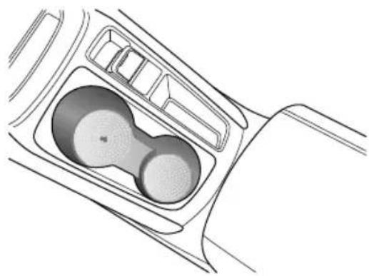
natural_image
Top-down line drawing of a car gear shift lever (no text or symbols)Thecentreconsolecupholderissituatedatthefrontend of thecentreconsolearmrestassembly.
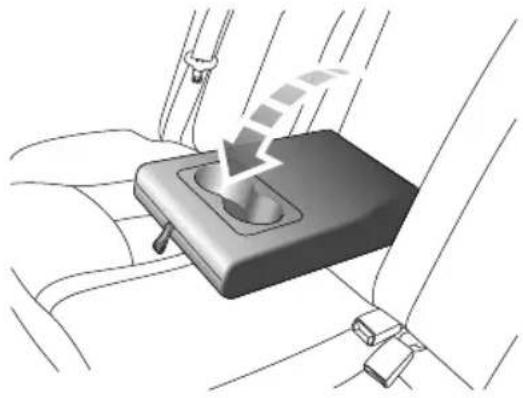
RearArmrestandRearCupHolder
natural_image
Diagram of a car seatbelt switch with a downward arrow indicating left motion (no text or symbols present)Foldforwardtoopenthereararmrest. Therearecup holdersatthefrontendofthereararmrest.
INSTRUMENTSANDCONTROLS
RoofLuggageRack \*

Theroofluggagerackisanon-load-bearing roofrack, which is used only as a decoration. Donotplace any load on the oroofluggage rack, otherwise it may result in an accident ordamageto the vehicle.
AirConditioning
64Ventilation
67ElectronicTemperatureControl *
72 AutomaticTemperatureControl *
AIRCONDITIONING
Ventilation
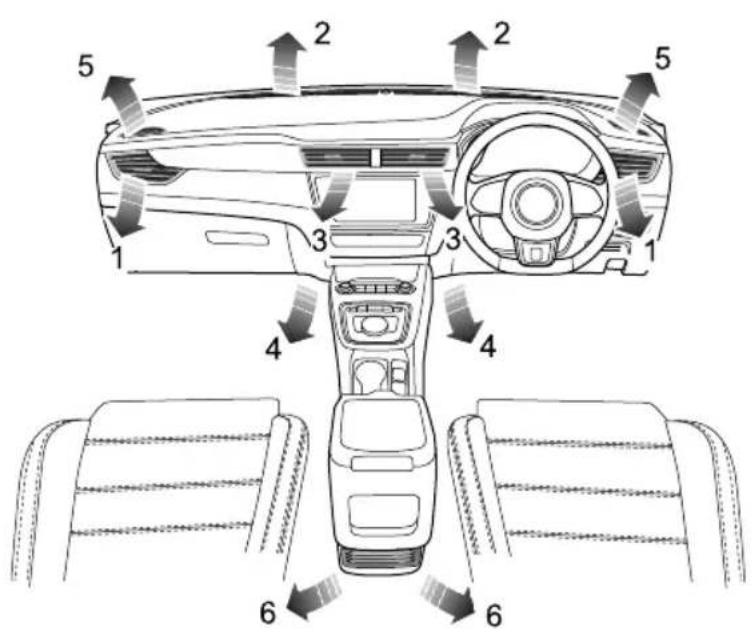
text_image
1 2 2 5 3 3 4 4 6 6I Side Vents
2Windscreen/DefrostVents
3CentreV ents
4FrontFootwellV ents
5FrontSideWindowV ents
6RearFootwellV ents
AIRCONDITIONING
Theheating,ventilationandairconditioningsystem providesfresh,coolingorheatedairtotheinteriorofthe car.Freshairisdrawninthroughtheairintakegrilleat thebaseofthefrontwindscreenandparticle/pollenfilter.
Alwayskeeptheairintakegrilleclearofobstructionssuch asleaves,snoworice.
Particle/PollenFilter
Theparticle/pollenfilterhelpstokeepthecarinteriorfree frompollenanddust. T oremainfullyeffective, thefilter shouldbereplacedattherecommendedserviceinterval.
Vents
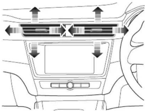
CentreVents
natural_image
Interior view of a car dashboard with directional arrows indicating traffic flow (no text or symbols)Slidethebuttoninthecentreofthelouvrescompletely to theleftorrighttoopenorclosethevent. T oggleitupand down, leftandrighttoadjusttheairdirection.
AIRCONDITIONING
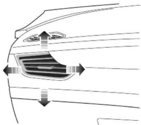
SideVents
natural_image
Diagram of a car's side profile showing airflow or traffic flow around the window (no text or symbols)Slidethebuttoninthecentreofthelouvrescompletelyto theleftorrighttoopenorclosethevent.T oggleitupand down,leftandrighttoadjusttheairdirection.
ElectronicT emperatureControl\*
ControlPanel
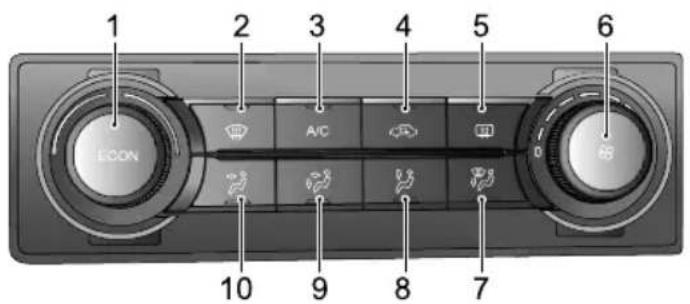
text_image
1 ECON 2 A/C 3 4 5 6 D 8 9 10IT emperatureControl Knob/EconomyModeButton
2Defrost/DemistButton
3CoolingOn/OffButton
4AirRecirculationmodeButton
5HeatedRearWindowButton
6BlowerSpeedControlKnob
7WindscreenandFeetMode Button
8FeetmodeButton
9FaceandFeetModeButton
10FaceModeButton
AIRCONDITIONING
InterfaceDisplay
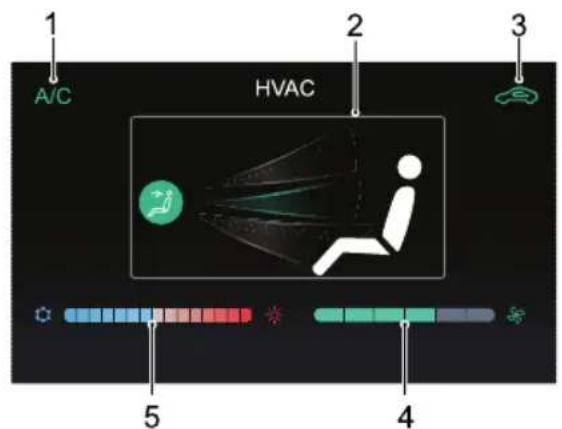
text_image
1 A/C HVAC 2 3 5 4I CoolingOn/OffDisplay
2AirDistributionModeDisplay
3AirRecirculationModeDisplay
- Externalcirculation
•Internalrecirculation

4BlowerSpeedDisplay
5T emperatureDisplay
BlowerSpeedControl
Rotatetheblowerspeedcontrolclockwisetoincrease theblowerspeedorrotateanti-clockwisetoreducethe blowerspeed.
Note: Selectblowerposition0toswitchtheair conditioningsystemOFF. Rotatetheblowerspeed knobtoblowerspeed lorabovetoswitchtheair conditioningsystemON.
EconomyMode
ECON
PresstheECONbuttononthecontrolpanel,
theairconditioningsystemwillenterEconomyMode, theindicatorinthebuttonwillilluminate.InEconomy Mode,theairconditioningsystemwillrunatlowenergy consumptionasprolongthedrivingrange.
AIRCONDITIONING
Note:
I SelectionofECONmodewillimpactsituations thatrequiremaximumheatingorcooling.
2 Whenthedefrost/demistfunctionisactivated, theairconditioningsystemwillautomaticallyexit ECONmode, andtheECONmodeindicatorwill extinguish.
CoolingOn/OffButton
A/C
Presstöoperate;theindicatorintheswitchwill
illuminateindicatingthattheaircoolingfunctionisswitched on.Pressagaintoswitchoff.
Note:
I Theventilationandheatingfunctionisstill availablewhentheaircoolingisswitchedoff.
2Thecooling/heatingmodeoftheairconditioning willonlyoperatewhenthevehicleisintheREADY state
3A smallamountofwatermayremaininthe airconditionerafterusage, this may produce a peculiarsmell. If this is a particular issue, it is recommended to switch the cooling function and run the blower for awhile.
TemperatureControl
Rotatethe TemperatureControlKnobtoadjusttheair temperatureinsidethecar.
AirDistributionMode
Select corresponding button to regulate their distributionmode as required.
| Operation Button | Interfacedisplay | AirDistribution Mode |
 | 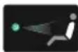 | FaceMode |
 |  | FaceandFeet Mode |
AIRCONDITIONING
| Operation Button | Interfacedisplay | AirDistribution Mode |
 | 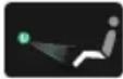 | FeetMode |
 |  | Windscreenand FeetMode |
FaceMode : Directsairtothesideandcentrevents.
FaceandFeetMode : Directsairtoside,centreand footwellvents.
FeetMode: Directsairtothefootwellvents.
Note: In this mode, as small amount of airflow will be directed to the beside, windscreen/defrost and front side windowvents.
WindscreenandFeetMode:Directsairtothefootwell, windscreen/defrostandfrontsidewindowwents.
Note: In this mode, asmall amount of airflow will be directed to the side events.
Defrost/Demist

Pressthisbuttononthecontrolpanelto
operatethedefrost/demistfunction,theindicatorwill illuminate. Thesystemwillautomaticallysetitselftoa presettemperatureandblowermotorspeedtoeffectively clearthesidewindowsandwindscreen.
Pressagaintoswitchoff. Thentheindicatorwillgooff, and thesystemwillreturntothepreviousstate.
Whilstthedefrost/demistisselected,operatetheA/C on/offbuttontoturnthecompressoron/off;operate theairrecirculationbuttontoswitchbetweeninternal recirculationandexternalcirculation,operationofeither ofthesefunctionswillnotaffectthedefrost/demist function,operationofanyotherairdistributionmodes willquitdefrost/demist.
HeatedRearWindow

Theheatingelementsontheinsideoftherear windowareeasilydamaged.DONOTscrape orscratchtheinsideoftheglass.DONOT sticklabelsovertheheatingelements.
Pressthisbuttononthecontrolpanelto operatetheheatedrearwindowfunction,theindicatorintheswitchwillilluminate.Theheatedrearwindowfunctionwillautomaticallyturnoffafteroperatingfor15minutes.Iftheswitchispressedagainwithin5minutes,theheatedrearwindowwilloperateandthenremainonforafurther8minutes.Pressingtheswitchwhilsttheheatedrearwindowisonwillswitchchoffthefunctionandextinguishtheindicatorintheswitch.
Note: The heated rear window will only operate when the vehicle is in the READY state.
AirRecirculationMode
Presstheairrecirculationmodebuttonto
switchtheairrecirculationmodetointernalrecirculation orexternalcirculation.Whentheindicatorilluminates,it isintheinternalrecirculationmode.
During internal recirculation, the air conditioningsystem circulate the air insidethe cartomeet therequirements of rapid cooling or heating, and at the same time, it can prevent the entry of traffic fumes.
During the external circulation, the air conditionings system draws air from outside the vehicle to ensure fresh air enters the vehicle.
Not leaving the systemininternalrecirculation mode can cause the windscreen to this happens, turn on the defrost/demist mode, adjust the blowerspeed and air temperature to are reasonable range.
AIRCONDITIONING
AutomaticT emperatureControl
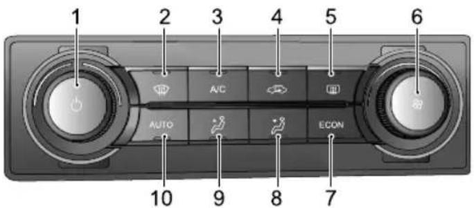
ControlPanel
text_image
1 2 3 4 5 6 AUTO A/C ECON 7 9 10IT emperatureControl
Knob/SystemOn/OfButton
2Defrost/DemisButton
3CoolingOn/OfButton
4AirRecirculationModeButton
5HeatedRealWindowButton
6BloweSpeedControKnob
7EconomyModeButton
AirDistributionModeButton
AiDistributionModButton2
10AutoModButton
AIRCONDITIONING
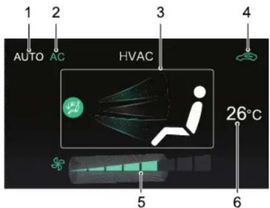
InterfaceDisplay
text_image
1 AUTO AC 3 HVAC 4 26°C 5 6IAutoModeDisplay
2CoolingOn/OffDisplay
3AirDistributionModeDisplay
4AirRecirculationModeDisplay
Externalcirculation
Internalrecirculation


5BlowerSpeedDisplay
6T temperatureDisplay
SystemOn/Off
PresstheSystemOn/OffButtononthecontrol paneltoswitchthesystemon, allfunctionswillrevertto thestatebeforeshutdown. Pressagaintoswitchoff.
NotTheconditioningsystemshouldonlyeswitchedoffviatheOn/Offbutton.
AutoMode
AUTO
Setthetargettemperaturerequiredandthen presstheAUTObuttontoenabletheautomodefunction. Iautomodeheidistributiomodandblower speedareautomaticallyadjustedtoreachandmaintainthe requiredtemperature.
Note: ensure the autamode operates efficiently, all windows and the sunroof musbeclosed and their inlet grill mus be clear of obstruction. In addition,
AIRCONDITIONING
thesolarsensorontheupperpartoftheinstrument panelshouldnotbecovered.
Manuallyadjusttheairdistributionmodeorblowerspeed toexitautomode.InthiscasetheAUTOindicatorwill extinguish.
EconomyMode
ECON
PresstheECONbuttononthecontrolpanel, theairconditioningsystemwillenterEconomyMode, theindicatorinthebuttonwillilluminate.InEconomy Mode, the air conditioningsystem will run at low energy consumption, soastoprolongthedrivingrange.
Note:
ISelectionofECONmodewillimpactsituations thatrequiremaximumheatingorcooling.
2Whenthedefrost/demistfunctionisactivated, theairconditioningsystemwillautomaticallyexit ECONmode,andtheECONmodeindicatorwill extinguish.
CoolingOn/OffButton
A/C
Presstöoperate;theindicatorintheswitchwill
illuminateindicatingthattheaircoolingfunctionisswitched on.Pressagaintoswitchoff.
Note:
I Theventilationandheatingfunctionisstill availablewhentheaircoolingisswitchedoff.
2Thecooling/heatingmodeoftheairconditioning willonlyoperatewhenthevehicleintheREADY state
3A smallamountofwatermayremaininthe airconditionerafterusage, this may produce a peculiarsmell. If this is a particular issue, it is recommended to switch the cooling function and run the blower for awhile.
TemperatureControl
Rotatthe TemperaturContröckwistet increase the temperature inside a rotate anti-clockwisetodecrease.
AIRCONDITIONING
BlowerSpeedControl
Rotatetheblowerspeedcontrolclockwisetoincrease theblowerspeedorrotateanti-clockwisetoreducethe blowerspeed.
AirDistributionMode
Selectandtoselecttheairdistributionmodeas required.Y oucanselectfacemode,faceandfeetmode, feetmodeorwindscreenandfeetmode.
| InterfacedisplayAirDistributionMode | |
| FaceMode | |
| FaceandFeetMode | |
| FeetMode | |
| InterfacedisplayAirDistributionMode | |
 | WindscreenandFeet Mode |
FaceMode : Directsairtothesideandcentrevents.
FaceandFeetMode : Directsairtoside,centreand footwellvents.
FeetMode: Directsairtothefootwellvents.
Note: In this mode, as small amount of airflow will be directed to the beside, windscreen/defrost and front side windowvents.
WindscreenandFeetMode:Directsairtothefootwell, windscreen/defrostandfrontsidewindowwents.
Note: In this mode, asmall amount of airflow will be directed to the beside events.
AIRCONDITIONING
Defrost/Demist

Pressthisbuttononthecontrolpanelto operatethedefrost/demistfunction,theindicatorwill illuminate.Thesystemwillautomaticallysetitselftoa presettemperatureandblowermotorspeedtoeffectively clearthesidewindowsandwindscreen.
Pressagaintoswitchoff. Thentheindicatorwillgooff, and thesystemwillreturntothepreviousstate.
Whilstthedefrost/demistisselected,operatetheA/C on/offbuttontoturnthecompressoron/off;operate theairrecirculationbuttontoswitchbetweeninternal recirculationandexternalcirculation,operationofeither ofthesefunctionswillnotaffectthedefrost/demist function,operationofanyotherairdistributionmodes willquitdefrost/demist.
HeatedRearWindow

Theheatingelementsontheinsideoftherear windowareeasilydamaged.DONOTscrape orscratchtheinsideoftheglass.DONOT sticklabelsovertheheatingelements.
Pressthisbuttononthecontrolpanelto operatetheheatedrearwindowfunction,theindicatorintheswitchwillilluminate.Theheatedrearwindowfunctionwillautomaticallyturnoffafteroperatingfor15minutes.Iftheswitchispressedagainwithin5minutes,theheatedrearwindowwilloperateandthenremainonforafurther8minutesBressingtheswitchwhilsttheheatedrearwindowisonwillswitchchoffthefunctionandextinguishtheindicatorintheswitch.
Note: The heated rear window will only operate when the vehicle is in the READY state.
AirRecirculationMode
Presstheairrecirculationmodebuttonto
switchtheairrecirculationmodetointernalrecirculation orexternalcirculation. Whentheindicatorilluminates, it isintheinternalrecirculationmode.
During internal recirculation, the air conditioningsystem circulate the air inside the cartome et therequirements of rapid cooling or heating, and at the same time, it can prevent the entry of traffic fumes.
During the external circulation, the air conditionings system draws air from outside the vehicle to ensure fresh air enters the vehicle.
Note:Leavingthesystemininternalrecirculation modecancausethewindscreentomist. If this happens, turnonthedefrost/demistmode, adjust the blowerspeedandairtemperaturetoareasonable range.
Note: WhenswitchingthesystemOFF, the vehicle automatically enters internal recirculation mode and the indicator illuminates.
Seats&Restraints
80Seats
86SeatBelts
97 AirbagSupplementaryRestraint System
105ChildRestraints
SEATS&RESTRAINTS
Seats
Overview

To avoid personal injuries duethelossof control, DONOT adjust theseatswhile the carismoving.
Anidealpositionoftheseatshouldmakesureyourdriving positioniscomfortable,whichallowsyoutoholdthe steeringwheelwithyourarmsandlegsslightlybentand controlalltheequipment.Makesureyourdrivingposition iscomfortableandenablesyoutomaintainfullcontrol ofthevehicle.T akecarewhenadjustingtheheightof frontseats-thefeetoftherearpassengercouldbecome trappedwhenteseatislowered.
DONOTinclinethefrontseatbackrestexcessively. Optimumbenefitisobtainedfromtheseatbeltwiththe backrestanglesettoapproximately25°fromtheupright (vertical). Thedriverandfrontpassengerseatsshould bepositionedasfarrearwardaspractical. Aproperly adjustedseathelpsreducetheriskofinjuryfromsitting tooclosetoaninflatingairbag.
HeadRestraints

Adjusttheheightoftheheadrestraintsothat thetopofitisinlinewiththetopofthe occupant'shead. Thislocationmayreduce theriskofheadandneckinjuriesintheevent ofacollision.DONOTadjustorremovethe headrestraintswhilethecarismoving.

DONOThanganythingonanyheadrestraint orheadrestraintrod.
Theheadrestraintisdesignedtopreventrearward movementoftheheadintheeventofacollisionor emergencybraking,therebyreducingtheriskofheadand neckinjuries.
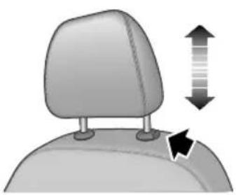
natural_image
Illustration of a car headrest with directional arrows indicating movement or change (no text or symbols)Whenadjustingaheadrestraintfromlowtohighposition, pulltheheadrestraintdirectlyupward,andgentlypress itdownwardafteritreachesthedesiredposition to makesurethatitislockedinposition.T oremovethe headrestraint,pressandholdtheguidesleevebutton(as indicatedbythearrow)ontheleftoftheheadrestraint, thenpulltheheadrestraintupwardtoremoveit.
Whenadjustingaheadrestraintfromhightolowposition, presstheguidesleevebutton(asindicatedbythearrow)on theleftoftheheadrestraint,andpresstheheadrestraint downward;releasethebuttonafteritreachesthedesired position,andgentlypresstheheadrestraintdownwardto makesurethatitislockedinposition.
FrontSeats
ManualSeat
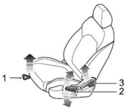
text_image
1 2 3•Forward/BackwardAdjustment
Liftthelever(1)undertheseatcushion, slidetheseat intoanappropriatepositionandreleasethelever.Make surethattheseatislockedinplace.
SEATS&RESTRAINTS
• CushionHeightAdjustment
Liftthelever(2)repeatedlytoraisetheseatcushion, presstheleverdownwardtolowertheseatcushion.
- BackrestAdjustment
Liftthelever(3),adjustthebackrestuntiltreachesthe desiredangle,returnthelevertotherestpositionand ensurethebackrestisinalockedposition.
PowerSeat *

text_image
B A 1 2 3•Forward/BackwardAdjustment
Pushtheswitch(I)forwardorbackward(A)tomove theseatforward/backward.
• CushionHeightAdjustment
Pulltheswitch(I) upwardorpushdownward(B) to raise or lower these at cushion.
- BackrestAdjustment
Movetheswitch(2)forwardorbackwardtoadjust backrestuntiltreachesthedesiredangle.
•LumbarSupportAdjustment
Movethelever(3)toadjustthelevelofthelumbar support.
RearSeats
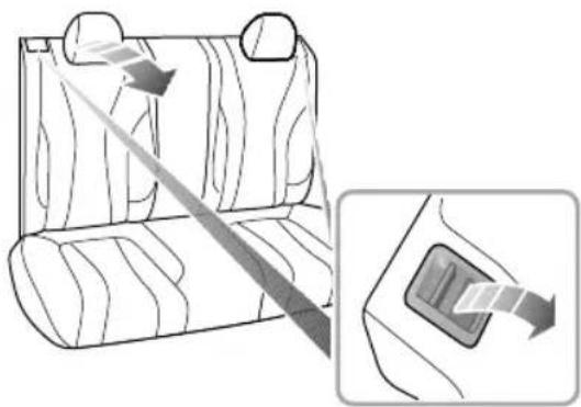
natural_image
Diagram showing a car seatbelt with a diagonal arrow indicating direction, and an inset view of the seatbelt (no text or symbols present)T oincreaseteluggagespace,therearseatbackrest canbefoldedfullyforward.Whenfoldingthebackrest completely, firstlyinserttherearseatbeltbuckleinto thecorrespondingslot,thenfullylower(orremove)all headrestraints,pulltherespectivecontrolleveratthetop oftheseatbackrestupwardsandfoldtheseatbackrest forward.
SEATS&RESTRAINTS
T oreturnthebackresttoanuprightposition,pullthe respectivecontrolleverupwardtoreleasethelock,raise thebackresttothedesiredposition,aclickwillbeheard whentheseatislocked.
Note: When returning therearseatbackrest to the desired position, makesure that therearseatbelt is not trapped.
Note: If therearseatheadrestraints are not fully lowered or the backrest of the front seat is inclined backward excessively, the folding of therearseatis very likely to damage the back of the front seat, small storage compartment or rearseat head restraint.
Note: If therearseatbeltbuckleisnotcompletely inserted into the correspondingslot, folding the backrest is very likely to damagetherearseatbackrest coverorfoam.
FrontSeatHeating \*

Ifbareskinisincontactwiththeheatedseats forexcessiveperiodsoftime,itmaycause burns.
Theseatcushionandbackrestareprovidedwithheating elements. AfterthevehiclepowermodeissettoREADY, pressiwillactivatetheheaters.
Whenpressingaseatheaterswitch, the corresponding seatwillbecomewarm. Presstheswitchagaintostop the heating function. Whenteseatheating function is activated, the operating indicator in the switchilluminates. Whenthe cushion temperature reaches approximate 38^ C or the backrest to approximate 40^ C, the heating function will be deactivated automatically.
IMPORTANT
•DONOTcovertheheatedseatswithblankets, cushionsorotherinsulationtypeobjectors materials.
- Iftheseatcushionisheatedupto38°Corthe seatbackrestisheatedupto40°Candcontinues gettinghotterwhenusingtheseatheatingsystem, pleaseturnofftheseatheatingandcontactanMG AuthorisedRepairer.
• Overuseofthedriver'sheatedseatmaycause drowsinessandcouldaffectsafety.
SEATS&RESTRAINTS
SeatBelts

It is important that all seat belts are worn correctly. Always check that all passengers are wearing seat belts. DONOT carry passenger that are unable to wear correctly positioned seat belts. Wearing seat belts incorrectly may cause serious injury over death in the event of a collision.

Airbags cannot replace seat belts. Airbags carry out support trigger air traffic accidents will trigger airbags. Whether airbags are triggered, seat belt can reduce the risk of serious injury or death in accidents. Therefore, seat belts must beworncorrectly.

NEVERunfastenaseatbeltwhilstdriving. Seriousinjuryordeathmayoccurinthecase ofanaccidentoremergencybraking.
Thisvehicleisequippedwithseatbeltwarning indyoutofastenyourseatbelt.
Duringdriving, seatbeltsmustbefastened, this is because: You came very predict if you wil be involved a collision accident and how serious it maybe. Many cases of collision accidents, passengers with seatbelts correctly fastened are well-protected, while passengers with seatbelts not fastened suffer from serious injury overvendeath.
Therefore, all passengers must wear seat belts correctly, evendurings short-distance journeys.
ProtectionProvidedbySeatBelts

Itisofequalimportanceforpassengersinthe rearseattofastentheirseatbeltscorrectly. Otherwise,passengerswithseatbeltsnot correctlyfastenedwillbethrownforwardin accidents,andwillendangerthemselvesas wellasthedriverandotherpassengers.
Whenthevehicleisinmotion,thetravellingspeedofthe occupantsisidenticaltothatofthevehicle.
Intheeventofa'headoncollision'oremergencybraking, thevehiclemaystop,buttheoccupantswillcarryon travellinguntiltheycomeintocontactwithastationary object. Thisobjectmaybethesteeringwheel,dashboard, windscreenandothers.
Acorrectlyfastenedseatbeltwilleliminatethisriskof injury. Whentheseatbeltisworncorrectly, itwilllock automaticallyincollisionaccidentsoremergencybraking toreduceyourspeedtogetherwiththevehicle, soas topreventtheout-of-controlmovementwhichmaycause seriousinjurytodriverandpassengers.
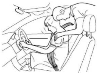
natural_image
Line drawing of a person assisting another in a car seatbelt (no text or symbols)SEATS&RESTRAINTS
WearingSeatBelts

Incorrectlywornseatbeltscouldcauseinjury ordeathintheeventofanaccident.

Seatbeltsaredesignedforoneperson.DO NOTshareseatbelts.

DONOTwrapaseatbeltaroundwhen holdingababyorchildinyourarms.

Removeanyheavycoatsorclothingwhen wearingaseatbelt,failuretodosocanaffect protectionprovidedbytheseatbelt.

Seatbeltsshouldnotbewrappedaround hardorsharpobjectssuchaspens, spectacles orkeys.

Seatbeltscannotfunctioncorrectlywhenthe seatsarereclinedexcessively.DONOTdrive whentheseatsareexcessivelyreclined.
Theseatbeltsfittedtoyourvehiclearedesignedforuse bynormalsizedadults. Thispartoftheliteraturerefersto adultuse.Foradviceonseatbeltusewithchildren,please see'ChildrenandSeatBelts'.
Allseatbeltsare3pointlap-shoulderbelts.
Inordertomaintaineffectiveprotection, the passengers must sit in the correct orientation, feet placed on the floor in front of them, with an upright body (no excessiverecline) and these at belt correctly fastened.
SEATS&RESTRAINTS
FasteningSeatBelts
Please follow the instructions below to fast these seat belts correctly.
I Holdthemetaltab, pull theseatbeltoutsteadily over the shoulder and across your chest. Ensure the belt is not twisted.
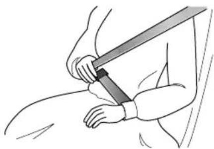
natural_image
Illustration of a person using a bandage to lift a wrist (no text or symbols)2Insertthemetaltabintothebuckleuntilyouheara 'click', this indicates these at belt is securely locked.
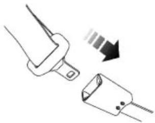
natural_image
Diagram showing two electrical connectors with a downward arrow indicating direction (no text or symbols)3Removeanyslacknessinthebeltbypullinguponthe diagonalsectionofthebelt.
4T oreleasetheseatbelt, presstheredbuttononthe buckle. Theseatbeltwillretractautomaticallytoits originalposition.
SEATS&RESTRAINTS
IMPORTANT
•Alwaysensuretheseatbeltwillnotbecometrapped inthedooraperturewhenclosingthedoor ,damage willoccur.
- Pullingtheseatbeltouttooquicklymaycauseitto 'lock'.Inthiscase,allowtheseatbelttoretract slightlyandthenpullitacrossyourbodyslowly.
- Ifitisdifficulttopulltheseatbeltout, itmaybe due to twistedwebbing. If this is the case, fully extract theseatbelt, removethetwist, allow theseatbelt to retract slowly.
- Whenusingtherearseatbeltspleaseensurethey arefullyretractedintothecorrectpositionto avoidjammingintherearseatcatches.Itisalegal requirementtowearseatbelts.Eveniftheseatbelt istwisteditmustbeworn.Wherepossibleavoid thetwistedsectioncontactingthebodyandseek advicefromanMGAuthorisedRepairerassoonas possible.
CorrectRoutingoftheSeatBelts

Ensuretheseatbeltiscorrectlypositionedon thebody,NEVERcrosstheneckorabdomen, NEVERpasstheseatbeltbehindthebackor underthearms.
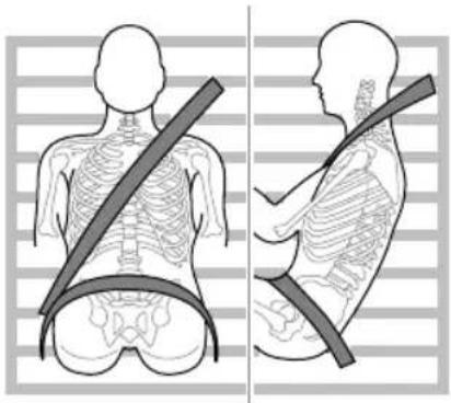
natural_image
Side-by-side illustrations of human torso showing skeletal contours and a belt, no text or symbols presentWhenwearingseatbelts,thelapbeltsectionsshouldbe positionedaslowaspossibleacrossyourhipNEVER crosstheabdomen.Intheeventofacollision,thelapbelt canapplyaforceonthehipsandreducethepossibilityof
SEATS&RESTRAINTS
youslippingunderthelapbelt.Ifyouslipunderthelap belt,thebeltwillapplyforceonyourabdomen,whichmay causeseriousorfatalinjuries.Thediagonalsectionofthe beltshouldcrossthemiddleoftheshoulderandthechest. Intheeventofemergencybrakingorcollision,thediagonal sectionofthebeltwillbelocked.NEVERpositionaseat beltacrossyourneck,acrossthebodyunderyourarmsor behindyourback.
To ensure that these seat belts always provide maximum protection, ensure the belt is flat, not loose and contacts the body.
SeatBeltsDuringPregnancy
Wearingcorrectlypositionedseatbeltswillprovide protectionforbothmotherandunbornchildintheevent ofacollisionoremergencybraking.
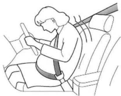
natural_image
Illustration of a person sitting in a car seat using a seatbelt, with no visible text or symbols.Thediagonalsectionoftheseatbeltshouldpassacross thechestasnormal,thelapsectionofthebeltshouldpass belowthebelly,lowandsnugonthehipbones.NEVER positionthebeltonorabovethebelly.
Please consult your physician for further details.
SeatBeltsandDisabilities
Itisalegalrequirementthatallooccupantswearseatbelts, thisincludepeoplewithdisabilities.
Dependinguponthedisability,consultyourphysicianfor furtherdetails.
SEATS&RESTRAINTS
ChildrenandSeatBelts

Properprotectionmeasuresmustbetaken forchildrenduringdriving.
Forsafetyreasons, childrenmustrideinachildrestraint devicefixedtotherearseat.
Infants

Only recommended child restraint suitable for the age, height and weight of the child should be used.

NEVERcarryachildorinfantwithyourarms duringdriving. Whencollisionaccidents occur, theweightofchildwillproducesuch agreatforcethatyoucannotholdthechild. Thechildwillbethrownforwardandsuffer seriousinjuryorevendeath.
Theseatbeltsfittedtoyourvehiclearedesignedforadults, theyarenotsuitableforchildren.Intheeventofan accidentorcollisionthechildrenarenotsecure,itcould causedeathorseriousinjury.
InfantsMUSTuseasuitablechildrestraintdevice.Please consultthechildseatmanufacturersguidelineswhen selectingthecorrectseat.Followthemanufacturers instructionsoninstallation.Pleasereferto"Child Restraints"inthischapterformoredetails.
OlderChildren

NEVERshareaseatbeltamongstchildren. Intheeventofanaccidentorcollisionthe childrenarenotsecure,itcouldcausedeath orseriousinjury.
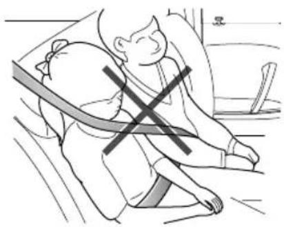
natural_image
Illustration of a person sitting on the floor with a cross symbol indicating pressure or stress (no text or symbols present)Aschildrengrowandbecomeolder/largeritwillgettothe stagewhentheynolongerrequirechildseatrestraints,at thispointtheywillrequireuseofthevehiclestandardseat belt.Pleaseensuretheseatbeltiscorrectlypositionedon thebodyofthechild.
When fastening seat belt for a child always check it for correct positioning. Adjust the height of seat belt to ensure the shoulder belt is kept away from the child's face and neck. Position the lap belt acrosst he hips as low as possible, and tighten adequately. Correct positioning means that these seat belt can pass the applied force to the strongest part of child's body in accidents.
If the shoulder belt to oocloseto child's face or neck, it may be necessary to use a child boost or cushion (always ensure that it meets any relevant laws or standards.
SeatBeltPre-tensioners

Theseatbeltpre-tensionerswillonly beactivatedonceandthenMUST BEREPLACED.Failureretoreplacethe pre-tensionerswillreducetheefficiencyof thevehicle'sfrontrestraintsystem.

If the pre-tensioners have been activated, the seat belt will still function as restraints, and must beworn in the event that the vehicle remains in drivable condition. These at bel pre-tensioners should bere placed at the earliest opportunity by an MGA authorised Repairer.
The vehicle is fitted with seat beltpre-tensioners, these are designed to retract these seat belts and work in conjunction with the air bags in the event of a severe collision. They are designed to retract these seat belt and secure the occupant in these at.
Theairbagwarninglightonthinstrumentpackwill alertthedrivertoanymalfunctionoftheseatbelt
SEATS&RESTRAINTS
pre-tensioners.(see 'WarningLampsandIndicators' in the 'InstrumentsandControls' chapter).
Theseatbeltpre-tensionerscanonlybeactivatedonce, afteractivationtheymustbereplaced. Thismayalso involvereplacementofotherSRScomponents.Please referto'ReplacingAirbagSystemParts'.
IMPORT ANT
- Seatbeltpre-tensionerswillnotbeactivatedby minorimpacts.
• Theremovalorreplacementofapre-tensionermust becarriedoutbythemanufacturertrained, dealer technicians. - 10 years from the initial date of registration (or installation date of fare placement seat belt pre-tensioner), some components will need to bereplaced. The appropriate page of the Service Portfolio must be signed and stamped for the vehicle servicerecords updated on each homework has been completed.
SeBled Maintenance Replacement
SeatBeltChecks

Split, wornofrayeseatbeltmaynot functioncorrectlyintheeventofacollision, ifthereareanysignsofdamage,replacethe beltimmediately.

Alwaysensuretheredreleasebuttononthe seatbelbuckleispointingupwardstoensure easyreleaseintheeventofanemergency.
Please follow the instruction below to check theseabelt warninglamp, seatbelt, metaltab, buckle, retractor and fixing device regularly:
- Inserttheseatbeltmetaltabintothecorresponding buckleandpullseatbeltwebbingclosetothebuckle quicklytocheckthatthebeltclasplocks.
Hold themetatabanqultheseabelforward quickly to check that theseatbeltreellocksautomatically, preventing the webbing from extending.
SEATS&RESTRAINTS
- Fullyextracttheseatbeltandvisiblyexaminefortwists, fraying,splitsorwornareas.
- Fullyextracttheseatbeltandallowtoreturnslowlyto ensurecontinualandcompletesmoothoperation.
- Visiblyexaminetheseatbeltformissingorbroken components.
- Ensuretheseatbeltwarningsystemisfullyfunctional. Iftheseatbeltfailsanyoftheabovetestsorinspections contactanMGAuthorisedRepairerimmediatelyfor repairs.
SeatBeltMaintenance

DONOTattempttoremove, install, modify, disassembleordisposeoftheseatbelts. Have anynecessaryrepairscarriedoutbyyourMG AuthorisedRepairer.Inappropriatehandling mayleadtoincorrectoperation.

Ensure no foreign sharp objects become lodged in these at belt mechanisms. DO NOT allow liquid to contaminate these at belt buckle, this could affect the buckle engagement.
Seatbeltsshouldonlybecleanedwithwarmsoapywater. DONOTuseanysolventtocleantheseatbelt.DONOT attempttobleachordyetheseatbelt,itmayweakenthe seatbelt.Aftercleaning,wipewithaclothandallowto dry.DONOTallowtheseatbelttofullyretractbeforeit iscompletelydry.Keepseatbeltscleananddry.
If there are contaminants accumulated in theretractor, the retraction of these at belt will be slow. Please use a clean and dry cloth to remove any contaminants.
SEATS&RESTRAINTS
ReplacingSeatBelts

Collisionaccidentsmaydamagetheseat beltsystem. Theseatbeltsystemmaynot beabletoprotectusersafterdamageand maycauseseriousinjuryorevendeathwhen anaccidentoccurs. Aftertheaccident,seat beltsshouldbecheckedimmediately and replacedasnecessary.
Seatbeltsshouldnotrequirechangeafterminorcollisions, however, someotherpartsoftheseatbeltsystemmay requireattention. PleaseconsultanMGAuthorised Repairerforadvice.
SEATS&RESTRAINTS
AirbagSupplementaryRestraint System
Overview

TheairbagSRSprovidesADDITIONAL protectioninaseverefrontalimpactonly.It doesnotreplacetheneed,orrequirementto wearaseatbelt.

The airbagstogether with these at belts provide optimum protection for adults, but it is not the case for infants. These at belt and air bags systems in the vehicle are not designed for protecting infant protection required by infant should be provided by child restraints.
TheAirbagSupplementaryRestraintSystemgenerally consistsof:
- FrontAirbags(fittedtothecentreofthesteeringwheel anddashboardabovetheglovecompartment)
- SeatSideAirbags(fittedtotheoutersideoftheseatsquab)
- SideHeadImpactProtectionAirbags(fittedbehindthe headlining)
Pleasenotethatthisismodelandtrimleveldependant.
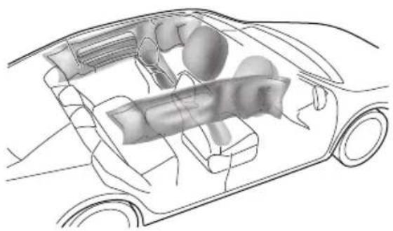
natural_image
Technical line drawing of a car interior showing internal components (no text or labels)SEATS&RESTRAINTS
In the corresponding position where air bags are fitted, there is awarningsignstating 'AIRBAG'.
AirbagWarningLight

Theairbagwarninglightislocatedinthe
instrumentpack.Ifthislampdoesnotextinguishor illuminatesduringdriving,itindicatesthatthereisafailure intheSRSorseatbelt.PleaseseekanMGAuthorised Repairerattheearliestopportunity.AnSRSorseatbelt faultmaymeanthecomponentsmaynotbedeployedin theeventofanaccident.
AirbagDeployment

Frontseatpassengersshouldnotplacefeet, kneesoranyotherpartofthebodyincontact with,orincloseproximitytoafrontairbag.

Tominimisetheriskofaccidentalinjuryfrom inflatingairbags,seatbeltsshouldbeworn correctlyatalltimes.Inaddition,bothdriver andfrontseatpassengersshouldadjusttheir seattoprovidesufficientdistancefromthe frontairbags.Ifsideairbags/sideheadimpact protectionairbagsarefitted,bothdriverand frontseatpassengeshouldbseatetb maintainsufficientdistancefromtheupper partofthebodytothesidesofthevehicle, thiswillensuremaximumprotectionwhen thesideairbags/sideheadimpactprotection airbagsaredeployed.
SEATS&RESTRAINTS

Whenairbagsaredeployed, childrenwithout properprotectionmaysufferfromserious injuryorevendeath.DONOTcarrychildren inthearmsoronthekneesduringtraveling. Childrenshouldwearseatbeltssuitableto age.DONOTleanoutofwindows.

Aninflatingairbagcancausefacialabrasions andotherinjuriesiftheoccupantistooclose totheairbagatthetimeofitsdeployment.

DONOTaffixorplaceanyobjectson, or adjacenttotheairbags. This may affect the airbagpassageorcreateprojectilesthatmay cause injuryorseriousharmintheeventof airbagdeployment.

Afterdeploymenttheairbagcomponents becomeveryhot.DONOTtouchanyairbag relatedcomponents,itmaycauseburnsor seriousinjury.

DONOTknockorstrikethepositionwhere airbagsorrelatedpartsarelocated,soas toavoidaccidentalairbagdeploymentwhich maycauseseriousinjuryorevendeath.
Intheeventofacollision, theairbagcontrolunitmonitors therateofdecelerationoraccelerationinducedbythe collision,todeterminewhethertheairbagsshouldbe deployed.Airbagdeploymentisvirtuallyinstantaneous andoccurswithconsiderableforce,accompaniedbya loudnoise.
Provided the front seat occupants are correctly seated and with seat belts properly worn, the air bags will provide additional protection to the chest and facial areas in the event of the car receiving a severe frontal impact.
Sideairbagsandsideheadimpactprotectionairbagsare designedtoofferadditionalprotectiontothesideofthe bodyfacingtheimpact,ifaseveresidecollisionoccurs.
SEATS&RESTRAINTS
IMPORTANT
•Airbags cannot protect lower body part sof passengers.
- Airbagsarenotdesignedforrearcollision,minor frontalorsideimpacts,orifthevehicleoverturns; norwillitoperateasaresultofheavybraking.
- Deployment and retraction of the frontal and side air bag stakes place every quickly and will not protect against the effect of secondary impact that may occur.
- Whenanairbaginflates,afinepowderisreleased. Thisisnotanindicationofamalfunction,however, thepowdermaycauseirritationtotheskinand shouldbethoroughlyflushedfromtheeyesandany cutsorabrasionsoftheskin.
•Afterinflation,frontandsideairbagsdeflate immediately. Thisprovidesagradualcushioning effectfortheoccupantandalsoensuresthatthe driver'sforwardvisionisnotobscured.
FrontAirbags

NEVERusearearwardfacingchildrestraint onaseatprotectedbyanACTIVEAIRBAG infrontofit,DEA THorSERIOUSINJURYto theCHILDcanoccur.

Frontseatpassengersshouldnotplacefeet, kneesoranyotherpartofthebodyincontact with,orincloseproximitytoafrontairbag.

lextremeasedrivingenyneven surfacesaycausirbagdeployment. Plesetakeextracarewhendrivingon unevenroads.
Airbagsaredesignedtodeployduringseriousimpacts,the followingconditionsmaycauseairbagdeployment.
- Afrontalcollisionwithunmovableornondeformable solidobjectsatahighspeed.
- Conditionsthatcancauseseriouschassisdamage,such asacollisionwithkerbstones,roadedges,deepravines orholes.
SeatSideAirbags

Themanufactureandmaterialoftheseat iscriticaltothecorrectoperationofside airbags. Therefore,pleaseDONOTfit seatcoverswhichmayaffectsideairbag deployment.
Intheeventofaserioussideimpact,therelevantsideairbag willdeploy(onlytheaffectedside).
• The airbag will be deployed in the event that the side of the vehicle is impacted with a solid object or another vehicle.
SideHeadImpactProtectionAirbags
thevenoferiousidempactheelevanside curtainairbagwilldeploy(onlytheaffectedside).
- Thesidecurtainairbagwillbedeployedintheeventthat thesideofthevehicleisimpactedwithasolidobjector anothervehicle.
Condition Which Airbag Not Deploy
The deployment of airbags does not depend on the vehicle speed, which has a single impact and therate at which the carchangess speed as result of a collision. When the impact force of collision is absorbed, dispersed to vehicle body, airbags may not deploy; however, airbags may sometimes deploy according to impact condition. Therefore, the deployment of airbags shall not be judged based on these severity of vehicle damage.
FrontAirbags
Undercertainconditionsthefrontairbagsmaynotbe deployedSomeexamplesarelistedbelow:
•Theimpactpointisnotcentraltothefrontofthe vehicle.
•Theimpactisnotofsufficientforce(theimpactiswith anobjectthatisnotsolid,suchasalamppostorcentral barriers).
•Theimpactareaishigh(collisionwiththetailgateofatruck).
- Impactstotherearorsideofthevehicle.
SEATS&RESTRAINTS
•Thevehiclerollingover.
SeatSideAirbagsandSideHeadImpact
ProtectionAirbags
Undercertainconditiontheseatsideandsidehead airbagsmaynotbedeployed.Someexamplesarelisted below:
•Sideimpactsatcertainangles.
•Lightsideimpactssuchasamotorcycle.
- Impactsthatarenotcentraltothesideofthevehicle, eithertoofartowardthefrontcompartmentorthe loadspace.
•Thevehiclerollingover .
•Theangledimpactisnotofsufficientforce(theimpact iswithanobjectthatisnotsolid,suchasalamppost orcentralbarriers).
•The impact is not of sufficient force (with another vehicle, stationary or moving).
•Theimpactisfromtherearofthevehicle.
ServiceandReplacementofAirbags
ServiceInformation

DONOTinstallormodifytheairbag.Any changestothevehiclestructureorairbag systemwiringharnessarestrictlyprohibited.

Changestovehiclestructureisprohibited. This may affect thenormaloperationofthe SRS.

DONOTallowSRSareastobefloodedwith liquidandDONOTusepetrol,detergent, furniturecreamorpolishestocleasIRS components..

IfwatercontaminatesorenterstheSRSit maycausedamageandaffectdeployment. InthiscasecontactanMAuthorised Repairerimmediately.
T opreventdamagetotheairbagSRS, the following areasshouldbecleanedsparinglywithadampclothand upholsterycleanerONLY:
•Steeringwheelcentrepad.
• Areaofdashboardcontainingthepassengerairbag.
- Areaofroofliningandfrontpillarfinisherswhich enclosethesideheadimpactprotectionmodules.
If the airbag warning lamp fail to illuminate, stay on, or if there is damage to the front side of the vehicle, or the air bag covers shows sign of damage, contact an MG Authorised Repairer immediately.
IMPORTANT
- Theremovalorreplacementofanairbagmodule shouldbecarriedoutbyanMGAuthorisedRepairer.
•After 10 years from the initial date of registration (or installation date of fare replacement airbag), some components will need to be replaced by an MG Authorised Repairer. The appropriate page of the Service Portfolio must be designed and stamped, or the vehicles servicere records updated on each homework has been completed.
ReplacingAirbagSystemParts

Eveniftheairbagdoesnotdeploy,collisions maycausedamagetoSRSinthevehicle. Airbagsmaynotfunctionproperlyafter damage,andcannotprotectyouandother passengerswhenasecondcollisionoccurs, whichmaycauseseriousinjuryoreven death.ToensurethattheSRScanfunction properlyafteracollision,pleasegotoan MGAuthorisedRepairertocheckairbags andrepairasnecessary.
Airbagsaredesignedforusingonceonly.Oncetheairbag isdeployed,youmustreplaceSRSparts.
PleasegotoanMGAuthorisedRepairerforreplacement.
DisposalofAirbags
When your vehicle is sold, ensure that the new owner knows the vehicle is equipped with air bags, and is aware of there replacement date of SRS.
SEATS&RESTRAINTS
If the vehicle is scrapped, the undeployed air bags may have potential risks, therefore, before the disposal, they must be deployed safely in a certain environment by a professional from MGA authorised Repairer.
ChildRestraints
ImportantSafetyInstructionsaboutUsing ChildRestraints
It is recommended that children below the age of 12 years old should be seated on there are seat of the vehicle, in a childrestraintsystem appropriateto the children's weight and size. Infants less than 2 years old should be restrained in an infant childrestraintsystem.
It is recommended that a child restraint system that complies with UNECE-R44 or ECE-R129 standard are fitted in this vehicle. Checkmarkings on the child restraint system.
Thereareanumberofchildrestraintsystemsavailableof differenttypeandspecification.Foroptimumprotection, itisrecommendedthatyouchooserestrainsystems appropriatetothechild'sageandweight.
It is important to comply with installation instructions supplied by the child restraint manufacturer and that child restraints system is properly secured to the vehicle. Failure to follow these instructions may cause death or serious injury to the child in an event of sudden stop or accident.
- Allooccupants, including children must wear seat belts or use an appropriate child restraint.
•MGstronglyrecommendsthatchildrenunder 12 years ofageorlessthan1.5metrestallshouldusethe appropriatechildrestraintfittedtotherearseat.
•Onlyonechildcanbecarriedinanyonerestraint.
•DONOTputthechildonthelaporinarmswhensitting inanyseat.
•Alwaysadjusttheseatbackresttoacentralposition andensureitislockedinpositionwheninstallingachild seatorrestraint.
• Ifinstallingarearfacingchildrestrainttotherear seat, thecorrespondingfrontseatshouldbeadjusted forward; ifinstallingaforwardfacingchildrestraint totherearseat, youmayneedtoadjusttheheight oftheheadresttothelowest; ifinstallingaforward facingchildrestrainttothefrontseat, youmayneedto removeitsheadrest. - Neverletyourchildstandorkneelontheseatduring driving.
•Alwaysensurethechilddisseatedcorrectlyinthechild restraint.
SEATS&RESTRAINTS
- Thewaysofusingseatbeltshaveagreatinfluenceon themaximumprotectionofferedbytheseatbelt,you mustcomplywiththechildrestraintmanufacturer's instructionsonproperuseofseatbelts.Ifseatbelts arenotproperlyfastened,aminortrafficaccidentmay alsoleadtoinjury.
- Childrestraintsthatarenotfittedcorrectlymaymove andinjureotheroccupantsintheeventofanaccident oemergencybraking. Therefore, evenifthereisno infantorchildinthechildrestraint, italsoshouldbe fittedproperlyandsecurelyinthevehicle.
WarningsandInstructionsonUseofChild RestraintonFrontPassengerSeat
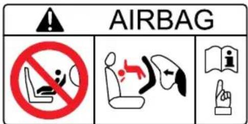
text_image
AIRBAG NO STOPPER SHEESE A B C D E F G H I J K L M N O P Q R S T U V W X Y Z
NEVERusearearwardfacingchildrestraint onaseatprotectedbyanACTIVEAIRBAG infrontofit,DEATHorSERIOUSINJURYto theCHILDcanoccur.

If you choosetoinstallachildrestraint on the front passenger seat at your front passenger seat as far rearward as possible.

Useonechildrestraintperchild.
Pleasestudythesafetywarningbelonthesunvisor. Wherepossiblealwaysinstallchildrestraintsontherear seatfinecessaryinstallchildrestrainorthefront seatpleaseobservethewarningsabove.
Children's Safety and Side Airbags

Children should not be allowed in areas where air bag map deployed theria risk of serious injury.

Only recommended child restraint suitable for the age, height and weight of the child should be used.

DONOTplaceanyitemsinareaswhere airbagsmaybedeployed,thereisariskof seriousinjury.
Intheeventofasidecollision,thesideairbagscanprovide betterprotectionforthepassenger .However ,when theairbagistriggeredaverystrongexpansionforceis generated,ifthepassenger'sseatingpositionisnotcorrect, theairbagsoritemsinthesideairbagdeploymentarea maycauseinjury.
Whenthecorrectchildrestraintisusedtosecurethe childproperlyintherearseatandthechild'sseating positioniscorrect,thereisenoughspacebetweenthe childandtheideairbagdeploymentregionfortheirbag todeploywithoutanyhindrance,andthusprovidethe bestprotection.
ChildRestraintsGroups
SecuredUsingPointapDiagonaBelts

Please DONOT put therear facing child restraint in the front passenger seat, this may cause serious injury or death.
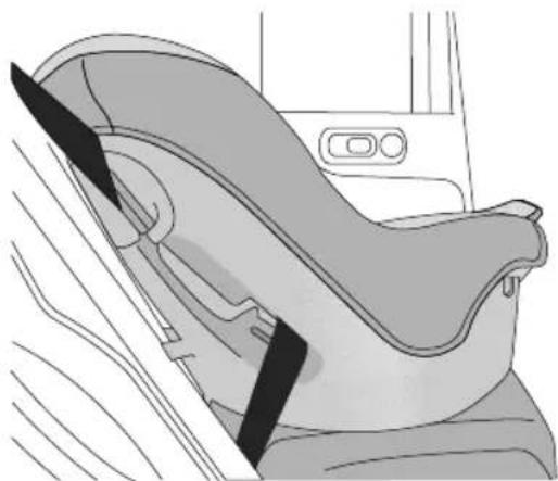
natural_image
Line drawing of a car seatbelt seat with black bandages, no text or symbols presentSEATS&RESTRAINTS
It is recommended that children should always be seated in therearof the vehicle in a child restraint or restraint system, and fixed with 3 point, lap diagonal seat belts.
ISOFIXChildRestraintSystems

TheISOFIXanchoragesintherearseatare designedforusewithISOFIXsystemsonly.

Childrestraintanchoragesaredesigned towithstandonlythoseloadsimposed by correctlyfittedchildrestraints. Underno circumstancesaretheytobeusedforadult seatbelts,harnesses,orforattachingother itemsorequipmenttothevehicle.
Note: When installing and using any child restraint system, always follow the manufacturer's instructions.
Note: Therearseatsfittedtothisvehicleareprovided withtheISOFIXinterface(asindicatedbythearrowin thefollowingimage),thesearedesignedtoconnectto anISOFIXchildseat.
Fastenvehicle-approvedISOFIXchildrestraint systemstothemountingbrackets.
2Whenusing|SOFIXmountingbracketsforseat mounting,universallyapprovedchildrestraintsystems forISOFIXmaybeused.
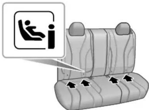
text_image
Diagram showing a car seat with a person inside the seatbelt and directional arrows indicating movement or movement.3T ofastentheT optetherstrapofthechildrestraint system, routethetetherstrapundertheheadrestraint andattachtotheanchoragehookbeingcarefulnotto twistthestrap.IfnotusinglSOFIXloweranchorages, usingtheseatbelt,completetheinstallationinlinewith thechildrestraintmanufacturesinstructions.
Note: When using seat mounting, universally approved child restraints systems, T optether must be used.
4Afterinstallationapplysuitableforcetoensurethe restraintissecurelyfastened.
Note: Pleaserefertothechildrestraintsystem manufacturer'sinstructionsfordetails.
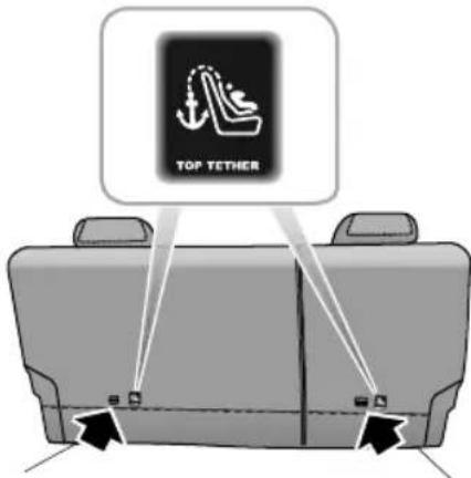
text_image
TOP YETHERSEATS&RESTRAINTS
ApprovedChildRestraintPositions
It is recommended that a child restraints system that complies with UNECE-R44 or ECE-R129 standard are fitted in this vehicle. Checkmarkings on the child restraints system.
ApprovedChildRestraintPositions(fornonISOFIXChildRestraints)
| MassGroup | SeatingPositions | ||
| FrontPassenger | RearOutboard | RearMiddle | |
| 0gtbup(lessthan10kg) U | X | ||
| 0+lgroup(lessthan13kg) U | X | ||
| lgldup(9 ~ 18kg) U | X | ||
| llgtbup(15 ~ 25kg) U | X | ||
| lllgloup(22 ~ 36kg) U | X | ||
| Note:Descriptionoflettersinthetable:U=Suitableforuniversalchildrestraintsystemsapprovedforthismassgroup;X=Seatpositionnotsuitableforchildrestraintsystemsinthismassgroup. | |||
ApprovedChildRestraintPositions(forISOFIXChildRestraints)
| SeatingPosition | Massgroupcategories | ||||
| 0group0+group | Igroup | ||||
| RearfacingForwardfacingRearfacing | |||||
| Upto29lbs(13kg)20-40lbs(9~18kg) | |||||
| FrontPassenger Seat | SizeClass | NotISOFIXequipped | |||
| SeatT ype | |||||
| RearOutboard SeatISOFIX | SizeClassC,D,E | 1 | A,B,B11 | C,D1 | |
| SeatT ype | IL2 | IL2,IUF3 | IL2 | ||
| RearCentreSeat | SizeClass | NotISOFIXequipped | |||
| SeatT ype | |||||
Not suitable for particular SOFIX child restraint of semi-universal category Please refer to vehicle list recommended by child restraint manufacturer;
IUF suitable for forward-facing SOFIX hildestraints universal category approved by this mas group and ISOFIX size class;
The SOFIX size class of both universal and semi-universarial child restraints defined by the capita letter grade to G. These identification letters are displayed on the SOFIX child restraints;
SEATS&RESTRAINTS
^2 Attimeofpublishingtherecommendedgroup0+ISOFIXchildrestraintistheBritaxRomerBabySafePlus;
^3 AttimeofpublishingtherecommendedgroupIIISOFIXchildrestraintistheBritaxRomerDuoPlus.
Note:AttimeofpublishingtherecommendedGroupII-IIIISOFIXchildseatistheKidFixXP .
T ableofl-Sizechildseats
Thetablegivesarecommendationforwhichl-Sizechildseatssuitwhichlocations,andforwhatsizeofchild.
ThechildseatmustbeapprovedinaccordancewithUNRegR129.
T ypeofchildseat
FrontpassengerseatRearoutboardseatsRearcentreseat
I-Sizechildrestraintsystems
XI-UX
Note:I-USuitableforusewithforwardandrearfacingl-Sizechildrestraintsystems.
XNotsuitableforusewithl-Sizerestraintsystems.
SEATS&RESTRAINTS
Group0/0+ChildRestraint

Whenthefrontpassengerairbagisactive, neverplacearearfacingchildrestraint on thefrontpassengerseat,severeinjuryoreven deathcanoccur.
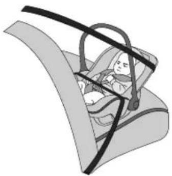
natural_image
Illustration of a baby car seatbelt in a car seatbelt (no text or symbols)Childrestraintsthatcanbeadjustedtolyingposition aremostsuitableforinfantswhoarelighterthan10kg (normallyforthoseyoungerthan9months)orthosewho arelighterthan13kg(normallyforthoseyoungerthan24 months).
GrouplChildRestraint

Whenthefrontpassengerairbagisactive, neverplacearearfacingchildrestraint on thefrontpassengerseat,severeinjuryoreven deathcanoccur.
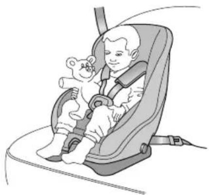
natural_image
Illustration of a child in a baby car seat with a teddy bear, no text or symbols presentBackward/forwardchildrestraintsaremostsuitablefor infantswhoseweightis9 \~ 18kg(normallyforthoseolder than9monthsandyoungerthan4yearsold).
SEATS&RESTRAINTS
GroupIIChildRestraint

Thediagonalsectionoftheseatbeltshould passacrosstheshoulderandupperbody, awayfromtheneck. Thelapsectionofthe beltshouldpassacrossthehips,awayfrom theabdomen.
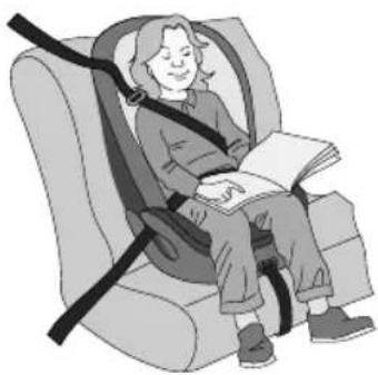
natural_image
Illustration of a person sitting in a car seat with a bandaged seatbelt, no text or symbols presentThe combination of child restraint and 3 point lap diagonal seat beltismost suitable for children whose weight is 15 \~ 25 kg (normally forthose older than 3 years old and younger than 7 years old).
GroupIIChildRestraint

Thediagonalsectionoftheseatbeltshould passacrosstheshoulderandupperbody, awayfromtheneck. Thelapsectionofthe beltshouldpassacrossthehips,awayfrom theabdomen.
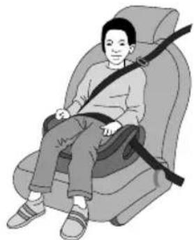
natural_image
Illustration of a person sitting in a car seat with a belt (no text or symbols)The combination of child booster seat and vehicle 3 point lap diagonal seat belt is most suitable for children whose weight is 22 \~ 36 kg and whose height is below 1.5 m (normally forthose about 7 years old to those older than 7 years old).
Starting&Driving
116Keys
120 ChildProofLocks
121 Anti-theft Systems
128StartingandStoppingthePower System
132 PedestrianAlertControlSystem
I33EconomicalandEnvironmentalDriving
I35VehicleControl
137ChargingRequirements
151 ElectricDriveT transmission
16 | BrakeSystem
I 72 StabilityControlSystem(SCS) and TractionControlSystem(TCS)
173TyrePressureMonitoringSystem (TPMS)
175 CruiseControlSystem *
178ParkingAid
181 LoadCarrying
STARTING&DRIVING
Keys
Overview

Pleasekeepthesparekeyinasafeplace-notinthevehicle!

Itisrecommendedthatsparekeysarenot keptonthesamekeyring , sincethismay causeinterferenceandpreventcorrectkey recognitionandthereforepreventthevehicle powersystemfromenteringREADYmode.

Thesmartkeycontainsdelicatecircuitsand mustbeprotectedfromimpactandwater damage,hightemperatureandhumidity, directsunlightandtheeffectsofsolvents, waxesandabrasivecleaners.
T wosmartkeysshallbeprovided.Bothofthemcan operatealllocks.
Thekeysprovidedtoyouhavebeenprogrammedto thesecuritysystemyourvehicle.Anykeythatisnot programmedtoyourvehiclecannotstartthevehicle.
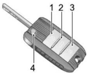
text_image
1 2 3 4ILockButton
2T ailgateReleaseButton
3UnlockButton
4SmartKey
Thesmartkeywillonlyworkwithinacertainrange.lts workingrangeissometimesinfluencedbythekeybattery condition,physicalandgeographicalfactors.Forsafety reasons,afterlockingthevehicle,checktoconfirmthat theoperationwassuccessful.
If your key is lost/stolenordamaged, are replacement can be obtained from a MG Authorised Repairer. The lost/stolen key can be deactivated. If the lost key is found, a MG Authorised Repairer can reactivate it.
Note:AnykeymadeindependentlyoutsideoftheMG AuthorisedRepairerNetworkmaynotallowyourcar toenterREADYmode,andmayaffectthesafetyof yourcar.Toobtainasuitablekeyreplacement,itis recommendedthatyoucanconsultMGAuthorised Repairer.
Not there can be offered by immediately because it requires programming to the vehicle by an MGA authorised Repairer.
Note: When operating the vehicle with a smart key, take care not to place the smart key closet devices with strong interference electron products
sudotebodomputerst,thenormal functionsofthekeymaybeaffected.
STARTING&DRIVING
ReplacingtheKeyBattery
Pleaseusethepictureguidetoreplacethekeybatteryif anyofthefollowingconditionsoccur:
• The effective operating range of the key is significantly reduced;
•Thevehicleimmobilisationwarninglamponthe instrumentpackflashes(Referto"WarningLightsand Indicators"in"InstrumentsandControls"section).
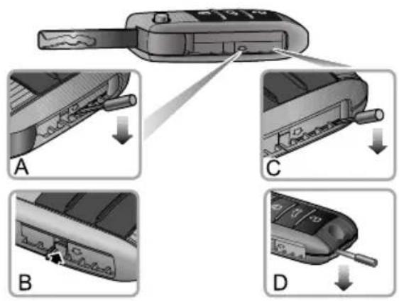
text_image
Diagram showing four steps of a mobile phone key being inserted, labeled A, B, C, and D.E
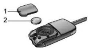
text_image
Diagram of a mobile phone with labeled parts, showing internal components and casing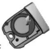
F
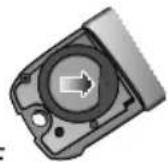
I Unfoldtheremotekey.
2Insertaflat-bladedtoolintoposition(A)showninthe figure,andapplypressureinthedirectionindicatedby thearrowuntiltheclipdisengages(B).
3 Insertaflat-bladedtoolintotheposition(C), and apply pressureinthedirectionindicatedbythearrowuntil agapappearsatthetailendofthekey.
4Insertaflat-bladedtoolintothegapatthetailofthe key,asshowninthefigure(D),slightlyprythebattery coveruntilthetwoclipsatthetailofbatterycover disengagecompletely.
5Carefullypriseoffthebatterycover.(1).
6Pressthefrontpartofbuttonbatteryusingslightforce (E)toremovethebattery(2).
7Positionthenewbattery, ensuring that correct polarity is maintained ("+" sidefacingup), slideitforward(F) ensuring it is fully inserted into the slot.
Note: Makesurethatthepolarityofbatteryis correct(positivesideupwards).
Note: It is recommended to use a CR2032 battery for theremote control.
8Refitthecoverandpresstightly.Checkthegaparound thecoveriseven.
9SetthevehiclepowermodetoREADYto resynchronizethekeywiththevehicle.
IMPORTANT
- Useofanincorrectorinappropriatebatterymay damagetheremotekey. Thenewreplacement's ratedvoltage, sizesandspecificationsmustbethe sameastheoldone.
•Incorrectfittingofthebatterymaydamagethekey.
- Disposaloftheusedbatterymustbestrictlyin accordancewithrelevantenvironmentalprotection acts.
STARTING&DRIVING
ChildProofLocks

NEVERleavechildrenunsupervisedinthe car.
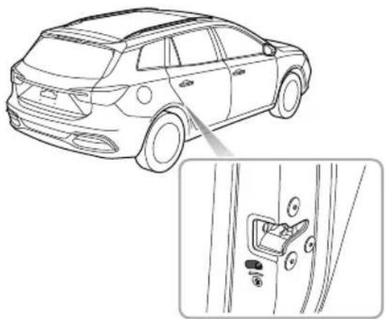
natural_image
Line drawing of a car showing the front side and side profile of the door (no text or symbols present)Stepsforenablingordisablingthechildprooflocksareas follows:
- Openthereardooratcorrespondingside,move thechildprooflocklevertothelockpositioninthe directionofthearrowtoengagethechildprooflock;
- Movethelevertotheunlockpositioninthereverse directionofthearrowtodisablethechildprooflock.
With the child proof locks engaged, there are doors cannot be opened from insidethe car, but can be opened from outside the car.
Anti-theftSystems
Y ourvehicleisfittedwithanpowerimmobiliseranda bodyanti-theftsystem.T oensuremaximumsafetyand operationconvenience,westronglyrecommendyouread thissectioncarefullytofullyunderstandtheactivationand deactivationofanti-theftsystems.
PowerImmobilisation
PowerImmobilisationisdesignedtosafeguardthevehicle fromtheft. Thepowerimmobilisationsystemcanonlybe deactivatedtostartthecarbyusingthematchedkey.
When the START/STOP switch is pressed and valid key is detected inside, the immobiliser is deactivated automatically.
Ifthemessagecentredisplays"SmartKeyNotDetected"or "PutKeyIntoBack-upPosition"orthepowerimmobiliser systemwarninglampilluminates,pleaseputthesmartkey atthebottomofthecentreconsolecupholder(referto "AlternativeStartingProcedure"in"StartingandStopping thePowerSystem"section),ortrytousethesparekey.If
thevehiclewillstillnotenterREADYmode,pleasecontact anMGAuthorisedRepairer
STARTING&DRIVING
BodyAnti-theftSystem
LockingandUnlocking
Whenthevehicleislocked, theindicatorlampsflashthree times; whenitisunlocked, theindicatorlampsflashonce.
KeyLocking
- Usingtheremotekeytolock:pressthelockbutton ontheremotekeytolockthevehicleafterclosingthe doors,bonnetandtailgate.
- Usingthemechanicalkeytolock:partiallyoperate thedoorreleasehandle,usingasuitableflatblade tool,insertthetoolintotheundersideofthetrimand carefullyremovethedoorlocktrimcover ,insertthe keyintothedriverdoorlockandturncounterclockwise tolockthecar.
KeyUnlocking
- Usingtheremotekeytounlock:presstheunlock buttononthekeytounlockthecar .
- Usingthemechanicalkeytounlock:partiallyoperate thedoorreleasehandle,usingasuitableflatblade tool,insertthetoolintotheundersideofthetrimand
carefullyremovethedriverdoorlocktrimcover,insert thekeyintothedriverdoorlockandturnclockwise tounlockthecar.
Note: If the vehicle powers system is not switched to the ACC/ON/READY position within 15 seconds after the vehicle is unlocked with the mechanical key, the immobilisation alarm will be triggered.
Note: If nop anels are opened within 30 seconds after the vehicle unlocked by using the remotkey all doors will automatically re-lock.
OperationofDoorLockSystem(Keyless) *
Thekeylessentrysystemcanlockandunlockthedoors andtailgateaslongasyoucarrythesmartkeyandapproach thecar.
IMPORTANT
Thesmartkeymustbewithin 1.5metresofthevehicle forthekeylesssystemtooperatecorrectly.
STARTING&DRIVING
KeylessLocking
AfterswitchingthevehiclepowersystemtoOFFusingthe START/STOPSwitchandexitingthecar,pressthedoor handlebuttononcebeforemovingawayfromthecarto lockalldoorsandtailgate(noneedtopressthelock buttononthekey).Note,thiswillalsoarmthealarmand immobilisethevehicle.
KeylessUnlocking
Pressthebuttononthefrontdoorhandleoncetounlock thecar,thenpullthedoorhandletoopenthedoor.
Note: Whenthevehicleislocked, if you are within the smart key range and operate the door handle button, but carry out no further action, after 30 seconds the vehicle will automatically re-lock itself to remain secure.
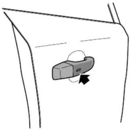
natural_image
Simple line drawing of a car door with a device inside, no text or symbols presentIMPORTANT
Afterthedoorislockedbyusingthekey,pressthe buttononthedoorhandletounlockthecar.Ifthecar cannotbeunlockedorlockednormally,seekanMG AuthorisedRepairer.
STARTING&DRIVING
Mislock
Ifthedriver'sdoorisnotfullyclosedwhenthesmartkey lockbuttonispressed,orthevehiclepowersystemhas notbeenswitchedOFF ,thevehiclehornwillsoundonce, indicatingamislock.Inthiscase,noneofthedoorswill lock,thealarmsystemwillnotbearmedandthedirection indicatorlightswillnotflash.
Ifthedriver'sdoorisclosed,thepassengerdoor ,bonnet andtailgatearenotfullyclosed,thehornsoundsonceto indicatemislockwhenthecarundergoeslockingoperation. However ,the'partialarming'attributesofthesecurity systemwillenableasmuchofthesystemtobearmedas possible(allfullycloseddoors,bonnetortailgateapertures willbeprotected,butanopendoorwillnot!).Thealarm indicatorwillflash.Assoonastheopenapertureisclosed, thesystemwillautomaticallyreverttoanarmedstate
InadvertentLockingofKeysinVehicle
If the vehicle is locked using the mechanical key blade or handset whilst a smart key/s remain inside, the following actions will occur:
- Onesmartkeylockedinthevehicle-The immobilisationreleasefunctionofthesmartkeylocked inthevehicleissuspended,thelockandunlockfunction ofthesmartkeyisretained.Thevehiclewillnotchange powerataeinstathienmobiliserelease functionofthesmartkeylockedinthevehiclethe secondsmartkeyshouldbeusedtounlockthevehicle. Thefunctionwillautomaticallybereinstated.
- Bothsmartkeyslockedinvehicle-Theimmobilisation releasefunctionofbothsmartkeyslockedinthevehicle issuspended,thelockandunlockfunctionofthesmart keyisetaineThevehiclewilllochangpower state.Thereinstatementofkeyfunctionscanonlybe carriedoutusingtheapproveddiagnostictool.Consult anMGAuthorisedRepairerimmediately.
Anti-TheftAlarmSounder
If the anti-theftalarm has been triggered, the car horn will sound continuously press the UNLOCK button the key, the anti-theftalarm will be deactivated.
STARTING&DRIVING
InteriorLockandUnlockSwitch
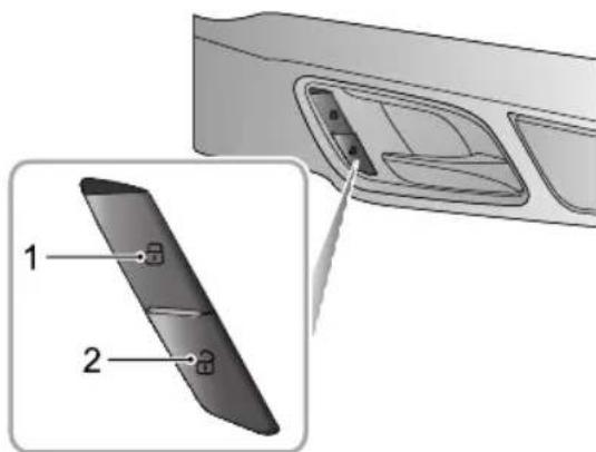
text_image
Diagram showing a device's internal structure with labeled parts 1 and 2, including a close-up view of the interior panel.ILockSwitch
2UnlockSwitch
Whenthevehicleanti-theftsystemisnotset,pressthelock switch(1)afterclosingalldoorstolockalldoors;pressthe unlockswitch(2)tounlockalldoors.
Note: If the vehicle anti-theft system is set, pressing the lock/unlock switch will not lock/unlock the doors but will trigger the alarms system.
Ifthedoors, bonnetandtailgateareclosed, press the interior lockswitch, they yellow indicator on the interior lockswitchilluminates.
lfamislockiscausedbyanon-driverdoor ,tailgateor bonnet,presstheinteriorlockswitch,theyellowindicator ontheinteriorlockswitchilluminates.
STARTING&DRIVING
InteriorDoorHandles
Usetheinteriordoorhandletoopenthedoor: 1 Pulltheinteriordoorhandleoncetounlockthedoor. 2 Pulltheinteriordoorhandleagaintoopenthedoor.
SpeedLock
Allthedoorswillbelockedautomaticallywhentheroad speedexceeds 10mph(15km/h).
AutomaticUnlock
When the START/STOP switched to the OFF position, all the doors will be unlocked automatically.
T ailgate
T ailgateOpenMode
Themanualtailgatecanbeopenedusingthefollowing2 methods:
I Longpressthereleasebuttononthesmartkey(B)for morethan2secondstounlockthetailgate. Then the tailgatecanbeliftedopen.
2Whenthevehicleisunlocked, directlypress the releaseswitch(A)onthetailgate. Thenthetailgate canbeliftedopen.
Note: Onvehiclesequippedwithkeylessentry, if a matchedkeyisdetectedwithinalmrangeofthe tailgatepressthereleaseswitch(A)onthetailgate, the tailgatecanthenbeliftedopen.
STARTING&DRIVING
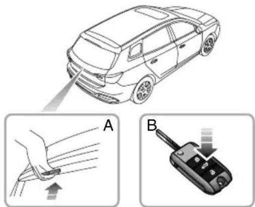
text_image
Diagram illustrating car safety instructions with labeled steps A and B showing hand positioning and device insertion.STARTING&DRIVING
StartingandStoppingthePower System
START/STOPSwitch
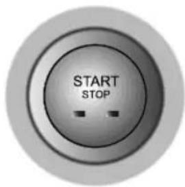
text_image
START STOPThekeylessSTART/STOPSwitchislocatedinthefasciato therightofthesteeringcolumn,itisapushbuttonstyle switch.T ooperatetheswitchthesmartkeymustbeinside thevehicle.
Theoperationalstatusdisplaysareasfollows:
IndicatorOff(OFF)
If the switch has not been operated and there are no indicators illuminated, the powersystem is OFF. The power electric doormirrors remain operational.
YellowLight(ACC)
PressingtheST ART/STOPSwitchwithoutthefootbrake beingappliedwhilstthevehiclepowersystemisOFFwill placethesystemintheACCstate,thiswillilluminatethe yellowindicatorintheswitchbuttonTheACCposition allowoperationcertaimcillariesucpower windows.
GreenLight(ON/READY)
WhilstintheACCstatpressingtheSTART/STOP Switchwithoutthefootbrakebeingappliedwillplace thesystemintheONstate,thegreenindicatorwill illuminateThiswillallowsomeelectricalsystemsto operate.
PressingtheST ART/STOPSwitchwithPselectedand theotbrakappliedwillacthehicliche READYstate,thegreenindicatorwillilluminatedThis indicatesthatalelectricalsystemswilloperateandthe vehicleisreadytobedriven.
Note: WhilstintheOFFstate, ifthedriverexitsthe vehicleleavingthesmartkeyinside, thehornwill soundthreetimesinquicksuccessionuponclosure ofthedriver'sdoor. Subsequentre-openingofthe driver'sdoorwilldisplayawarningmessageinthe instrumentpackmessagecentretoidicatethatthe keyisstillinthecar.
Note: T oremovetheelectronicshiftcontrolknobfrom PthevehiclemustbeinanON/READYstateandthe footbrakeapplied.
If your carissubjecttostrongradiosignalsthekeyless entry and start systemsmaysuffer from interference and not function correctly. Please see the 'Alternative Starting' procedure.
READYMode
SettingthepowersystemintoREADYmode:
I Ensure all unnecessary electrical loads (incAC) are switched off.
2 Ensure the parking brake is applied.
3EnsurePorNisselected(Iftheshiftcontrolknob isinanyotherpositionthepowersystemcannotbe switchedtotheON/READYstate).
4Pressbrakepedal.
5PresstheSTART/STOPSwitch(donotholdthebutton in, releaseimmediately).
6ThegreenindicatorwillilluminateandREAD Ywillbe displayedintheinstrumentpackmessagecentre.
STARTING&DRIVING
IMPORTANT
- If the vehicle will not enter a READY state, please check for any warning indicators or messages displayed in the instrument pack message centre. In extremely low temperatures please allow 5 minutes between power up attempts, if after 3 attempts the power state cannot be set to READY please consult an MGA authorised Repairer or breakdown service.
- DonotleavethepowersysteminanACCor ON/READYstateforlongperiodsoftime,excessive useofelectricalequipmentmayleadtotoadischarged battery.
•Thevehicleisfittedwithananti-theftsystem. Independentlysourcedkeysmaynotallowvehicle entryandsystempowerup.Anynewkeyswillrequire programmingusingthemanufacturerssoftware. - Yourcarisfittedwithcomplexelectroniccontrol systempleaseasuretherdio transmissionorelectromagneticdevicesarekept awayfromthesmartkeyandcentreconsolecubby areas. Theymaycauseinterferenceandoperational issues.Pleaseesethe'AlternativeStarting'procedure.
AlternativeStartingProcedure
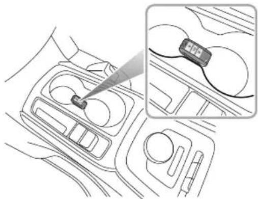
natural_image
Diagram showing a car interior with a device being inserted, and a close-up of a handheld device on the right side (no text or symbols present)If the vehicle is located in an area where there are strong radiosignals causing interference or the smart key battery condition is low, please use the following step to attempt to start the car:
Placethesmartkeycentrallyinthecentreconsolecup holdercubbyboxwiththebuttonsfacingupward-as shownintheillustration.
STARTING&DRIVING
2EnsurePorNisselected, pressthebrakepedaland thenpressSTART/STOPSwitchtopowerthevehicle.
Note: The Alternative Starting Procedures should only berequired if the smart key battery is very low or flat. Once the vehicle has been removed from the area of excessive radio interferencethe key less entry and START/STOP system should return on normal.
SwitchingthePowerSystemOFF
SettingthepowersystemtoOFF:
I After bringing the cartoahalt, ALWAYS maintain brake pedal application.
2Usingtheelectronicshiftcontrolknobselect(P)and applytheparkingbrake-pleasecheckthattheparking brakeisapplied.
3PresstheSTART/STOPSwitchtoshutdownthe powersystem.
Note: Pleaseobservetheparkbrakewarninglight andmessagedisplayedintheinstrumentpack
messagecentreconfirmingthattheparkingbrake isappliedbeforeexitingthevehicle.
Note: Should the powersystem require to be shut down in the case of an emergency, press and hold the START/STOP switch in excess of 4 seconds.
STARTING&DRIVING
PedestrianAlertControlSystem
Inordertoimprovethesafety,yourcarisfittedwitha
PedestrianAlertSystem.Whenthevehicleistravellingat alowspeed,thesystemcontrolsaspeakerthatsoundsto remindpedestriansinthevicinityofyourpresence.
SoundStrategies
Thespeakersoundswhenallofthefollowingconditions aremet:
I ThevehicleisREAD Y;
2ThePedestrianAlertSystemisfaultfree;
3Duringacceleration,thevehiclespeedisabove0mph (0km/h)andlessthan19mph(30km/h);during deceleration,thevehiclespeedisgreaterthan0mph (0km/h)andlessthan,orequalto15mph(25km/h).
EconomicalandEnvironmentalDriving
Running-in
Thebrakesandtyresneedtimeto'bed-in'andadjustto thedemandsofeverydaymotoring.Duringthefirst900 miles,pleaseavoidheavybrakingwherepossible.
EconomicDrivingandMaintenance
The following a resomes suggestions on saving power and extending the life of the vehicles.
- Maintain the correctty repressure; low pressures will result in accelerated tyrewear and increase power consumption.
- Donotcarryunnecessaryweight.Heavyloadswill increasethevehicleloadresultinginhigherpower consumption.
- Avoidcontinuousaccelerationordeceleration.A stop-godrivingstylewillconsumemorepower.
- Avoidunnecessarystoppingandbraking,maintaina steadyspeedandattempttoanticipatetrafficlights.
Note: Keepanappropriatedistancefromother vehiclestoavoidemergencybrakingandreduce brakepadwear.
- Avoidtrafficcongestionandjamareasasmuchas possible.
- Anticipatingobstructionsandslowingdownwellin advance,avoidstheneedforunnecessaryacceleration andharshbraking.Asmoothdrivingstylecanreduces powerconsumption.
- Donotridethebrakepedal, this can cause premature wear, overheating and increased power consumption.
- Maintainanappropriatespeedonthehighway. Higher speedsusemorepower. Appropriatespeedcansave power.
- Maintainthecorrectwheelalignment.Avoidcollisions withthekerbandreducespeedonunevenroad surfaces.Outofspecificationwheelalignmentwillnot onlyleadtoexcessivetyrewear,butalsoincreases the vehicleloadandpowerconsumption.
- AvoiddrivingonmudorbeacheThiswillprevent corrosionofthevehicleunderside.
STARTING&DRIVING
- Maintain the vehicle in accordance with MG recommendations..
Note: To extend the life of all components and reduce operating costs, regular MGA approved maintenance is needed.
- Useofelectricalequipmentwillreducethepower availablefromthebattery.Whilstitisessentialto maintainacomfortableinteriorenvironment,excessive useofsystemsuchasA/Cwillincreasepower consumptionandreducethevehiclerange.
DrivinginSpecialEnvironment
DrivinginRainorSnow

Emergencybraking, accelerating and steering onslipperyroadswillreducethevehicle's handlingperformanceandgrip.
- Whenrainingthewindowsmayfog,reducingvisibility (UsetheAir-conditioningdemistfunction).
•Gripwillbereduced,sopleasedrivecarefully. - Avoidaquaplaning(theeffectofafilmofwaterbetween thetyresandtheroad)thiswilleffectsteeringand brakingperformance.
DrivingthroughWater
Avoiddrivingthroughfloodsafterheavyrain,whichmay leadtoseriousdamagetothevehicle.
VehicleControl
VehicleControlSystem
The vehicle control system is used to collect data regarding the requirements from the driver (accelerator pedal, brake pedal, gear shift selection etc), it uses this information to adjust the driving stability and ride comfort, and to limit the output torque of the vehicle according to the vehicle condition (practical capabilities of current high-voltage battery pack and drivemotor).
DrivingMode
The driver is a bit to select different driving modes, suit their requirement. Indifferent driving modes, the vehicle control system can be used different control strategies for output control. For operation mode, please refer to 'Driving Mode' in Electric Drive Transmission chapter.
EnergyRegeneration
Whilst the vehicle is in an over-run, coasting or braking condition the vehicle will enter the KERS mode, converting part of the kinetic energy into electric energy by driving
themotor, which is then stored in the high-voltage battery pack.
The driver can choose different energy recovery levels as required for operation mode, pleasereferto 'Energy Regeneration' in ElectricDrive Transmission chapter.
CruiseControl
Thecruisecontrolfunctionenablesthedrivertokeep the vehicle Advancingtonstanspeed without the requirement to operate the accelerator pedal. Thedriver can select the cruisesettings by operating the leverswitch. Pleasereferto "CruiseControlSystem" chapter for the operation mode.
PowerLimitofElectricalAppliances
According to the current load condition and the status of low-voltage battery vehicle limit the power of some comfort electrical appliances, such as restricting partial lighting, air conditioning blower at the same time, the prompt information will be displayed in the information centre in the instrument pack.
STARTING&DRIVING
IMPORTANT
Ifanyoftheconditionsdescribedaboveoccur,please chargethelowvoltagebatteryassoonaspossible.
STARTING&DRIVING
ChargingRequirements

Undernormalcircumstancesitisstrongly recommended that you use as low charging method, avoid constant or regular use of rapid chargers.

Priortousinganychargingequipmentplease inspectthesockets,plugsandcablesforany damage.DONOTuseanyequipmentthat showssignsofmisuseordamage.

It is recommended that the charging cable be connected to the charging device before connecting to the vehicle and charging commences.

DONOTattempttoswitchthevehiclepower systemtoREADYduringcharging.

Afterchargingcompletion,switchoffthe charger(wherenecessary),disconnectthe cablefromthevehicle,fittthewaterproof blankingplugs(2pinsocketcoverfirst),close thechargingpointdoor.Ifnecessaryyoucan thendisconnectthecablefromthecharger (whereapplicable).

Whilstchargingthecaronrainydays, where possible, please avoidconnectingthecharger duringtorrentialrainorstorms. If excessive waterisevidentaroundthechargingplugs please use as suitable clothdodrythearea as best possible before removing the waterproof blankingplugs and connecting the charging cables.

DONOTtouchthechargingconnector chargingplugwhenyourhandiswet.

DONOTstandinwaterorsnowwhen connectingordisconnectingthecharging cable.
STARTING&DRIVING

DONOTattempttochargewhenthe chargingconnectorandplugarewet.

Alwayskeepthechargingconnector and chargingplugincleanandinadrycondition. Besuretokeepthechargingcable in a condition where there is now water or moisture.

Onlyusethecorrectchargerforchargingthe electricvehicle. Usinganyotherchargeror connectorconfigurationmaycausefailure.

T akecarenottodropthechargingconnector. Thiscouldresultindamage.

STOPchargingimmediatelyify you find anythingabnormal such as park burning or smoke.

Always hold the charging onnect handle op luy hen o nnect ing rem oving the charging able to put the able t self (without using the handle), the internal wires may disconnectogetdamaged. This may leadtoelectricshockorfire.

Highvoltagechargingequipmentcancause interferencewithelectronicmedicaldevices. When using medical electric devices such as apacemaker, please consult you doctor about whether charging your electric vehicle will impact the operation of the device. In some instances, electromagnetic waves that are generated from the chargercanseriously impact medicalelectric device operation.

NEVERuseahighpoweredjetwashdirectly onthechargerdoorortocleanaroundthe chargepoint.
ChargingY ourVehicleatHome
Whilst your MG has been supplied with a home charging kit its essential that you check with a qualified electrician that the infrastructure of your property will support the charging equipment. Please seek qualified advice that your current electrical supply and circuit will support the requirement of the charging equipment.
InstalledChargingPoints
Various companies will supply and install charging points to your property, MG insist that only qualified reputable suppliers and installers are used - failure to have the correct equipment installed by a qualified professional may result in overloaded circuits and fire.
HomeChargingGuide
ONLYusecertifiedapprovedequipment.
ONLYusequalifiedsuppliersandinstallers.
Whenthebatteryisfullycharged, disconnect the cable plug from the vehicles socket-ifitis necessary to interrupt the charging of the vehicle, disconnect the vehicle plug first, then isolat the powers supply.
NEVERallowwaterorfluidstoenterorcontaminateyour chargerorvehiclechargingsockets.
NEVERusedamagedchargingpoints, equipmentor sockets.
STOPchargingimmediatelyifyouseeanythingunusual, smellburningorseesparks.
ALWAYSfollowtheoperatinginstructionssuppliedwith yourchargingequipment.
Not charging in power supply infrastructure, installed service by suitable qualified personnel approved installation companying by materials recommended by them.
STARTING&DRIVING
ChargingandMedicalConditionAwareness

Highvoltagechargingequipmentcancreate areasofstrongelectromagneticinterference, thismaycauseoperationalissueswith electronicmedicaldevices.
When using medicalelectrical device such as pacemakers or cardioverter defibrillators (ICD's) please consult your doctor about whether charging you are electric vehicle will impact on the operation of the device. Insome instances, electromagnetic waves that are generated from the charger can seriously impact medicalelectric device operation.
Note: Therearenocautionsissuedaboutmedical deviceswhenthecarisnotconnectedtoachargepoint andcharging.Itisperfectlysafeforindividualsfitted withpacemakersorcardioverterdefibrillatorstodrive orrideinthevehicle.
ChargingPort
Thechargingportislocatedbehindthechargingportdoor centrallymountedinthefrontbumper.
T oopenthedoor,ensurethevehicleisunlocked,pressthe MGbadgeandrelease-thedoorwillopentorevealthe waterproofplugcovers.
Removetheplugcoverstorevealthecombinedcharging port.
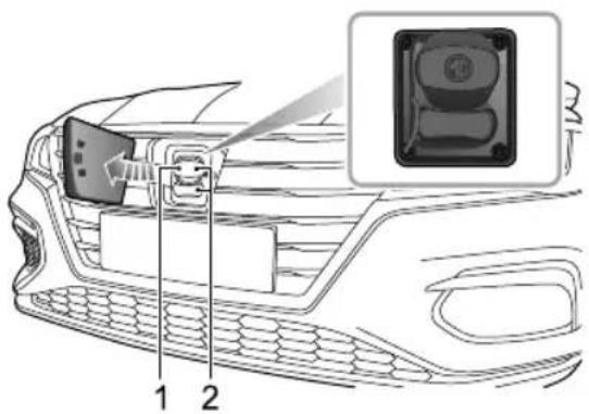
text_image
Diagram of a car front panel with labeled parts and an inset showing a close-up of the camera module.ISlowandFastChargePort-7Pin-T ype2Plug
2RapidChargePort-7Pinand2Pin-CCST ypePlug
Theupperplugcoversthe7pinslow/fastchargingsocket (1),thelowerplugcoverstherapidchargingsocket(2).
Note: Inordertousetherapidchargersocketboth waterproofplugcoverswillrequireremoval.
Aftercharging, refitthewaterproofplugcovers(2pinrapid chargesocketcoverfirst), closethechargingportdoorand usingtheMGbadge, pushthedoorfullyhomeuntilthe latchlocates.
ALWAYSensurethatanyexcesswaterisremovedfrom theportareabeforeconnectinganychargingdevice.
ChargingPortElectronicLock
Inordertopreventthechargingconnectorandcablebeing disconnectedinadvertentlyduringcharging,thecharging socketfeaturesanelectroniclockingmechanism.
Theelectroniclockisactivatedassoonasthevehicle islocked, and remainsinalockedstateuntilthecaris unlocked.
Whilst the charging cable is connected and the vehicle locked DONOT attempt to remove the plug.
Onlywhenthevehicleisunlockedcanthecharging connectorbeunplugged.
Note: The car will not chargewhilstinan unlocked state. During charging if the charging ports unlocked charging will be suspended, it will reinstate when the charging port is locked again. Charging does not automatically recommence pleaseremove and refit the charging cable.
STARTING&DRIVING
ManuallyReleasingtheChargingPortLockin EmergencySituations
The vehicle features an emergency released device for the charging portlock.
T oaccessthemanualrelease,raisethebonnetandremove thefrontcompartmentdecorativecover-seepicture.
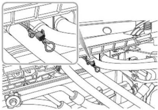
natural_image
Technical line drawing of a mechanical assembly with no visible text or symbolsPullthereleasecablehandle,removetheconnectorplug whilstmaintainingtensiononthecablethiswillreleasethe lockingdevice.
RapidCharging
Note: Pleasereadanyequipmentoperating instructionscarefullypriortousingtherapidcharging station. Eachtypeofchargermayusedifferent instructions.
Note: The cable of the charging plug should be shorter than 30m.
If you have any doubts please seek professional assistance.
RapidChargingSafetyPrecautions
- Beforeconnectingtherapidcharger, switchthevehicle powersystemOFFandwait10seconds.
Note: If at any time during the charging process you should want to check the state of charge, please switch the vehicle powers system to the ON position. The high voltage battery state of chargewill bed displayed in the message centre in the instrument pack.
SlowCharging
Note Carrying out a full slow charge is the only way for high voltage battery contact optimal equilibrium state (equalisation charge).
Highkoltagbatterychargerareavailablewithvarious poweroutputChargerwithOutputSP&W aregenerallyconsideredasslowchargers,7-22kWare consideredfastchargersandrapidchargersareavailablein ACorDCOutputs.GenerallytheACchargersarerated at43kWandtheDCchargersat50kWplus.
Chargingtimesaredependantonchargeroutput.
T ocarryoutanequalisationslowchargeitisrecommended thatthechargeroutputdoesnotexceed7kW .
STARTING&DRIVING
ACChargingPoints
IMPORTANT
PleaseensurethatonlychargepointsthatmeetIEC61851andIEC62196areusedtoconnecttoyour vehicle.
UsinganACchargingdevice:
I Ensure vehicle powersystem is OFF and all doors are closed.
2Openthechargingportdoor,removethewaterproof plugcoverfromthe7pinchargingplugconnector.
3Plugthecablefromthechargerpointintothevehicle. Lockthevehicle.
4Oncompletionofthechargeunlockthevehicleand disconnecttheplugfromthevehicle.
5Ensurethechargesocketisfreefromdebris,fitthe waterproofplugcover.Closethechargingpointdoor.
Note: If at any time during the charging process you should want to check the state of charge, please switch the vehicle powers system to the ON position. the high
voltagebatterystateofchargewillbedisplayedinthe messagecentreintheinstrumentpack.
Note: If the vehicle is unlocked during the charging process, charging will be suspended charging while a time in the charging does not automatically resume, it may be necessary to remove and fit the chargercable.
ResidentialCharging
Y ourvehiclewillhavebeensuppliedwitharesidential chargingdevice. This device can be plugged into a standard household 3 pin socket.
During the charging operation the vehicle powers system must be OFF. Carry out the following procedure to charge the car using the chargers supplied with the vehicle:
I Ensure vehicle powers system is OFF and all doors are closed.
2Openthechargingportdoor,removethewaterproof plugcoverfromthe7pinchargingplugconnector. Ensurethesurroundingsareclean,dryandfreefrom debris.
3Connectthe7pinchargingplugtothesocketonthe vehicle.
4Connectthechargingdevice3pinplugtothedomestic electricitysupply.Lockthevehicle.
5Oncompletionofthechargeunlockthevehicle, disconnectthechargingcablefromthevehicle,and thenthedomesticplug.
6 Ensure the charges socket is free from debris, fit the waterproof plug cover. Close the charging point door.
Note: If at any time during the charging process you should want to check the state of charge, please switch the vehicle powers system to the ON position. The high voltage battery state of chargewill bed displayed in the message centre in the instrument pack.
Note: If the vehicle is unlocked during the charging process, charging has spent charging while a time in which it does not automatically resume, it may be necessary to remove and fit the chargercable.
STARTING&DRIVING
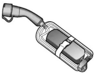
natural_image
3D rendering of a mechanical device with a curved handle and internal components (no text or symbols visible)Slowchargingkit(suppliedwiththevehicle)
ChargingInformation
Atthebeginningofthechargingprocess,thefollowinginformationwillbedisplayedwithintheinstrumentpackmessage centre.
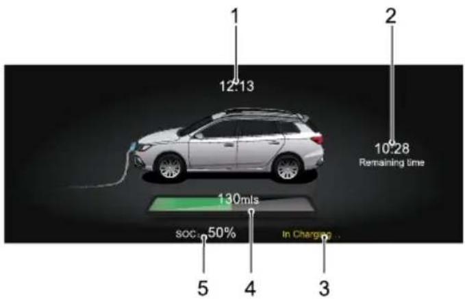
text_image
1 12.13 2 10.28 Remaining time 130 mls SOC 50% In Charge 5 4 3I Currenttime
2Chargingtimeuntilfull
3Chargingstatus
4Drivingrange
5Highvoltagebatterypackstatus
STARTING&DRIVING
EqualisationCharging
Equalisationchargingmeansthatafteranormalcharging processthebatterymanagementsystemwillenteramode whereitwillattempttoequalisethechargeofevery batterycell.
Ifanequalisationchargehasnotbeencarriedoutforsome timethemessagecentreintheinstrumentpackwilldisplay 'PleaseChargeforBMSBalance'.Pleasereferto'Slow Charging'inthe'StartingandDriving'section.
Onaverageittakesatleast7.5hourstocompletecharge thatincludestheequalisationcharge.
Note: Ambienttemperatureshaveaneffecton chargingtimes, it may takelongertocompletea chargewhentheambienttemperaturesarelow.
ChargingTimes
Chargingtimesofthehighvoltagebatterycanvary dependinguponnumerousfactors,theseinclude:current capacity,chargingmode,ambienttemperatureanddevice type/power.
RapidChargingTime
Rapidchargerswillvaryinpoweroutput,onaverageit willtakeapproximately40-60minutestochargethehigh voltagebatteryupto80%(80%displayedinIPK)usingan averagerapidcharger.
Note: Ambienttemperatureshaveaneffecton chargingtimes, it may takelongertocompletea chargewhentheambienttemperaturesarelowor high.
SlowChargingTime
Onaverageittakesapproximately7hourstochargethe highvoltagebatteryfromlowbatterywarningto100% (chargequantitycarbecheckedusingtheinstrumentpack).
Atowtemperaturesthechargingtimewilbæxtended.
STARTING&DRIVING
- Ifanequalisationchargehasnotbeenconductedfora longtimetherequiredchargetimewillbeextended.
- Anequalisationchargemustbecarriedoutpriorto usingthecarafteralongperiodofstorageornonuse. Inthesecasesthechargingtimewillbeextended.
Note: Theslowchargingnotesaboverelatetousingan ACchargingdevicewithanoutputratingof7kW. Use of the slow charging devices supplied with the car using adomestic powersupply can increase the charging times by up to 3 times.
IndicativeChargingTimes
Note: Thesetimesareonlyaguide.
| Rapidcharging | Fromalarmstatus(thehighvoltagebatterylowwarningdisplayedintheinstrumentpackmessage centre)to80%,ittakesalmost40minutes. | |||
| Slow charging | Residential electricity | Fromalarmstatus(thehigh voltagebatterylowwarning displayedintheinstrument packmessagecentre)to100% (thehighvoltagebattery stateofchargedisplayedin theinstrumentpackmessage centre),ittakesalmost20 hours. | Fromalarmstatus(thehigh voltagebatterylowwarning displayedintheinstrument packmessagecentre)to100% (thehighvoltagebattery stateofchargedisplayedin theinstrumentpackmessage centre)andequalisation, takesalmost20.5hours. | takeapproximatedequalisationchargeforfirstuseaftervehiclehasbeenparkedorstoredforalong time. |
| AC charging station | Fromalarmstatus(thehigh voltagebatterylowwarning displayedintheinstrument packmessagecentre)to100% (thehighvoltagebattery stateofchargedisplayedin theinstrumentpackmessage centre)dealmosthours. | Fromalarmstatus(thehigh voltagebatterylowwarning displayedintheinstrument packmessagecentre)to100% (thehighvoltagebattery stateofchargedisplayedin theinstrumentpackmessage centre)andequalisation, takesalmost7.5hours. | Ittakesapproximately9hours tocompleteequalisation chargeforistuseafterthe vehiclehasbeparkedor storedforalongtime. | |
ElectricDriveT transmission
Instructions
The following information is very important, pleaseread carefully before use:
•Theelectricdrivetransmissionconsistsofahighvoltage unit.DONOTtouchanydrivecomponentsunlessyou havethecorrecttrainingandqualifications.
- BeforesettingthevehiclepowersystemtoON,please ensurethatPorNisselected,theparkingbrakeAND footbrakeareapplied.
- WhenthevehiclepowersystemisREADY, usetheshift controlknobtoselectyourrequiredgear.
- Releasetheparkingbrakebutmaintainfootbrake applicationuntilyouarereadytomanoeuvre.Onaflat road,onceyoureleasethefootbrakeyouwillbeginto move,slowlyapplytheacceleratortoincreaseyour speed.
GearShiftControl
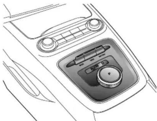
natural_image
Line drawing of a car interior air intake console with control panel and buttons (no text or symbols)Note: The highlighted letters in the information centre indicate these selected gearormode.
STARTING&DRIVING
ShiftControlKnobPosition

DoNOTturntheshiftcontrolknobtoeither PorRfromtheDpositionwhilstdriving orwhilstthevehicleisinmotion. This will cause severityedamagetotheelectricdrive transmissionorcauseanaccident.
•PPark
Whentheshiftcontrolknobisinthisposition, the electronicparkingbrakeisapplied. Onlyselectthisgear whenthevehicleisstationary.
Note: The electronic parking brakesystem must be released via the EPB switch. See "Electronic Parking Brake (EPB)" under the "Brake System" section.
Note: Whentheelectronicparkingsystemfailsto beactivated, the vehicle will enable the parking function of the electric drivetransmission, the P gear indicator on the shift control knob will flash. Operating the shift control knob to select any other gear will exit Park.
•RReverse
Select this gear only when the vehicle is stationary and you wish to drive backwards.
•NNeutral
Select this gear when the vehicle is stationary (for example, waiting for traffic lights).
•DDrive
Thisisusedfornormaldriving.
ShiftControlKnobOperation

DONOTpresstheshiftcontrolknobwhilst driving.
STARTING&DRIVING
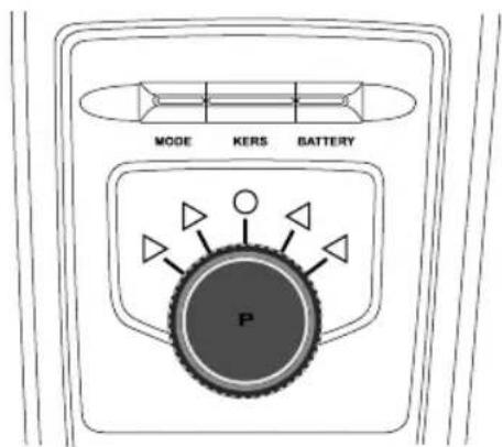
text_image
MODE KERS BATTERY PTheshiftcontrolknobhas5availablepositions:
Thepositionisthedefaultandtheonlyfixedposition, anymovementoftheknobwillreturntothisposition.
The and positions aresprungloaded momentary positions, after selection the knob will automatically return to the central default position.
Inordertopreventaccidentaloperationbypassingthe buttontheshiftontrdnobekquirearmpresso
operateandselectPaslongastheotherspecificselection requirementsaremet.
T ocarryoutagearshift,operatetheshiftcontrolknobas perthefollowinginstructions:
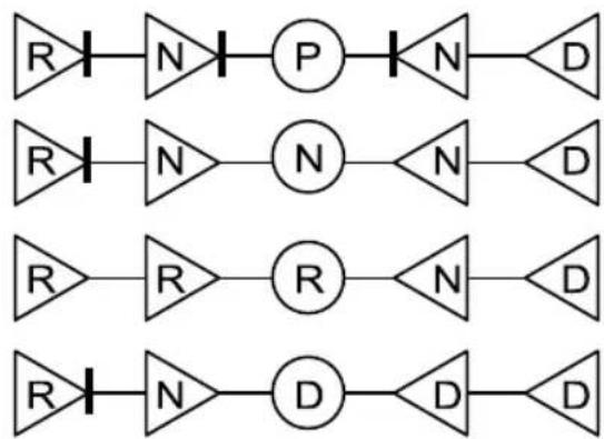
flowchart
graph TD
    A["R"] --> B["N"]
    B --> C["P"]
    C --> D["N"]
    D --> E["D"]
    F["R"] --> G["N"]
    G --> H["N"]
    H --> I["N"]
    I --> J["D"]
    K["R"] --> L["R"]
    L --> M["R"]
    M --> N["N"]
    N --> O["D"]
    P["R"] --> Q["N"]
    Q --> R["D"]
    R --> S["D"]
O Currentgear.
▶ △ Unlockedpositions.
Applyfootbraketoallowselection.
STARTING&DRIVING
Precautions:
•The initial gear position after powering the vehicle will be P . Whenswitching to the R, Dor N position the footbrake MUST be applied.
- WhenswitchingtotheRpositionfromtheNposition, thefootbrakeMUSTbeapplied.
- If the vehicles speed is below 1 mph (2 km/h), the shift control knob can be pressed to select and engage P.
• If the vehicles speed is below 1 mph (2 km/h) and the START/STOP switch is operated top power the vehicle OFF, P will automatically be selected and engaged.
- If the vehicles speed is below 1 mph (2km/h), the footbrakereleased, the river seat belt unfastened and the river door opened, will automatically be selected and engaged.
- ForsafetyreasonsALWA YSapplythefootbrakewhen shiftingbetweenRandDpositions.
VehicleStart-off
The vehicle can only be switched to a READY modewith Por N selected and the foot brake applied.
Afterselectingyourdesiredgearposition,waitinga veryshorttimefortheelectricaldrivetransmissionto engageandreleasingthebrakepedal,youshouldpressthe acceleratortostartdriving.
DrivingonHills

Incaseswhereashortstoponahillis required,suchasatrafficjam,DONOT momentarilyapplytheacceleratororto prevent"rollback".Thiscouldcausethe electricdrivetransmissiontooverheator evensystemdamage.
HillStart
Incasesofahillstart,thestartassistfunctionofthe electronicparkingbrake(EPB)canbeusedtopreventthe vehiclefromrollingbackwards.Fordetailsofthisfunction, pleasereferto"ElectronicParkingBrake(EPB)"in"Brake System'section.
Models fitted with HillHoldControlcanusethisfunction to assist hillstarts. Fordetailsonhillholdcontrolsystem, pleasereferto "HillHoldControlSystem" in "Brake System'section.
Note: Theaidofthesefunctionscannotdefythe law#physicDONO Drivathvehiclbeyonds physicallimitations,lossofcontrolwillstilloccur.
DrivingMode(MODE)

Please avoid itching between driving Modeswhilstdriving, this may divert the driver's attention away from road conditions and cause accident.
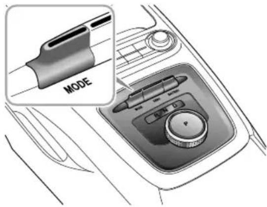
text_image
MODEThedrivercanmanuallyselectthreedrivingmodesby operatingtheMODEswitchonthecentreconsole:Eco ModeNormaModeandSporMode.
STARTING&DRIVING
- Themessagecentreintheinstrumentpackwilldisplay: E(EcoMode), N(NormalMode), S(SportMode).
T oggletheMODEswitchforwardorbackwardtoswitch betweenthreedrivingmodes.
Everytimethevehiclepowersystemiscycledandthe systemsettoREADY ,thedrivingmodedefaultstoNormal Mode.
Indifferentdrivingmodes, the control system uses different control strategies for output control.
EcoMode
EconomyModeoptimisesenergyconsumption, this will provide the best results regarding the range of the vehicle.
NormalMode
NormalModecombineseconomyandperformanceto meetthedrivingrequirementsofmostdrivers.
SportMode
SportModeconcentratesonprovidingmorepowerto enhancetheperformance.
Note: ConstantuseofSportModewilldecreasethe rangeofthevehicle.
Note: It is recommended to choose the Sport Mode when driving inspecial road conditions such as mountainroads.
Selectingdifferentdrivingmodeswillalsoautomatically selectthesettingsofthersystemssuchaselectronic steeringandA/C-pleaseseethechartbelow:
| Driving Mode | Power Mode | Steering Mode | A/C Mode | Brake Mode |
| Eco Eco | ||||
| Normal | Normal | Normal | ||
| Spont | Dynamic | Spont |
NotchilscModelectedhA/Gill operateinalowenergyconsumptionstatetoprovide anincreaseinvehiclepower.
EnergyRegeneration(KERS)

Decelerationeffectedbyenergyregeneration isNOTasubstituteforbrakingsafely. The drivermustALWAYSbepreparedtomake brakingmanoeuvrestomaintainsafedriving.
Whenthevehicleisinabraking,over-runorcoasting state,theenergyregenerationfunctionisactivated,and themotorconvertspartofthekineticenergyofthevehicle intoelectricenergy,whichisthenstoredinthehighvoltage battery.
Energy cannot be generated or is limited undersome conditions, such as:
• Ngearisselected(DuringdrivingdonotcoastinN gear);
- During torque intervention (SCSorption control operation);
• Highvoltagebatteryisfullycharged;
•Highvoltagebatterytemperatureistoohighortoolow.
Theenergyregenerationsystem(KERS)hasthreelevels:
Heavy
HeavyLevel:Maximumenergyisregenerated,thevehicle exhibitsshortercoastingdistancesandastrongsensation ofover-rundragormotorbraking.Theinformationcentre displays ③.
Moderate
ModerateLevel: moderateenergyregenerated. The informationcentredisplays ②。
Light
LightLevel: Minimumenergyisregenerated, the vehicle exhibits on coasting distance and significant sensation of over-rundragormotorbraking information centredisplays ①。
STARTING&DRIVING
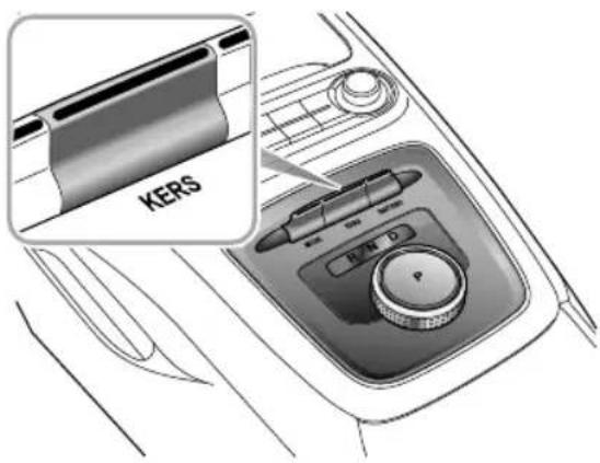
text_image
KERS R/N DThe driver can manually select three energy regeneration levels by operating the KERS switch in the centre console.
T oggletheKERSswitchforwardorbackwardtoswitch between three energy regeneration levels.
Everytimethevehiclepowersystemiscycledandthe systemsettoREADY ,theenergyregenerationlevels defaultstoHeavyLevel.
ItisrecommendedtochooseLightorModeratelevelson surfacesthathavelowadhesionlevels(e.g.icyroads).
ProtectionMode

When parking the vehicle, please ensure the vehicle is sparked safely and that all traffic by-laws are observed.
MotorOverheatingProtectionofElectricDrive
T transmission
The electric drivetransmission may become every hot in a high-temperature environment with frequent starting, frequent rapid acceleration and deceleration, long-term continuous steep climbing, and overload of the electric drivetransmission. In order to prevent damage to the motor, the system will perform an overheating protection function, the warning indicator illuminates, and the warning message "Motor Overheating" displays simultaneously. After a few seconds, the warning message will disappear but the warning indicator will remain on.
Inthiscase, park your vehicles safely or keeping a low load, continuet drive your vehicle at a constants speed to cool the motor. Only when the motor temperature has
decreased, the warning indicator is off, and the warning message disappears, can the vehicle bedriven normally. If the electric drivetransmission has cooled down for a longtime (about 20 minutes) and the warning indicator has disappeared please park the vehicles safely and seek an MGA authorised Repairer immediately, otherwise it may seriously damage the electric drivetransmission.
IMPORTANT
Whenthemotoroftheelectricdrivetransmission isdeoverheatingprotectionordet avoid damagethemotor,thepowerofthevehiclewill belimited(theinformationcentrewilldisplay"Power LimitedLimitingSpeedandWarning Indicator willilluminate).Afterdecelerating,thewarningswill disappearhethermotemperaturereturn to normal.

MotorFaultofElectricDriveTransmission
ifufailunidetecteihmotothe powerelectronicboxofelectricdrivetransmission,the warningindicaltonmates,andthewarningmessage
STARTING&DRIVING
"MotorFault" displayssimultaneously.PleaseseekanMG AuthorisedRepairerimmediately.
ParkingSystemFaultofElectricDrive
T transmission
Ifafaultorfailureisdetectedintheelectricalparkmotor controlunit,thewarningindicatorilluminates,and thewarningmessage"ParkingSystemFault"displays simultaneously.Afterafewseconds,thewarningmessage disappearsbutthewarningindicatorwillremainon, pleaseseekanMGAuthorisedRepairerimmediately.
LimpMode
Insomecases,whenafaultorfailureisdetected,the electricdrivetransmissionwillenterLimpModeandwill onlyfunctionatcertainspeedshewarningindicator illuminates,andthewarningmessage“SystemFault” displayssimultaneously.Afterafewseconds,thewarning messagedisappearsbutthewarningindicator remainopleaseseekanMAuthorisedRepairer immediately.
SevereFunctionalMalfunction
Insomecases,whenafaultorseverefailureisdetected inthelectricdrivetransmission,thewarningindicator illuminates,andthewarningmessage“SystemFault” displayssimultaneously.Afterafewseconds,thewarning messagedisappearsbutthewarningindicator remainon.T oprotecttheelectricdrivetransmission,the powersystemwillisolatethepowertransmission,andthe vehiclecannotbedriven,pleaseseekanMGAuthorised Repairerimmediately.
Insomecases,whenafaultorseverefailureisdetectedin thegearshiftsystem,theinformationcentrewilldisplay "ERForsafetyreasons,ifthevehiclespeedisbelow apresetspeed,thepowersystemwillisolatethepower transmissionandthevehiclecannobdrivenpleaseseek anMGAuthorisedRepairerimmediately.
BrakeSystem
FootBrake
Foradded safety, the hydraulic braking system operates through dual circuits. If one circuit should fail, the other will continue function, but greater pedal pressure will be needed, brake pedal travel will increase, and longer stopping distances will be experienced. In the event of a brake failure where only one circuit is operational, the car should be brought to a halt as soon as a traffic conditions safely allow. DONOT continued driving-seekan MG Authorised Repairer.
WetConditions
Drivingthroughwaterorheavyrainmayadverselyaffect brakingefficiency.Inthiscase,keepasafedistancefrom othervehiclesandintermittentlyapplythebrakepedalto keepthebrakediscsurfacedry.
ElectronicHydraulicBrakeApplication System(EHBS)
The vehicle is equipped with an electronic hydraulic brake applications system; always be aware of the following during the operation:
•TheEHBSsystemfunctionswiththevehiclepower systeminREADYmodeonly.Neverallowthevehicle tofreewheelwiththepowersystemturnedoff.
- If the powersystem should switch off for any reason while driving, bring the cartoahaltas quickly astraffic condition safely allow, and depress the brake pedal with greater force. DONOT continued driving-seeking MGA authorised Repairer immediately.
- If the EHBS system performed degrades dueto allow battery or other reasons, you need to apply more force than usual to the brake pedal to stop the vehicle.
- If the EHBS system fails, the instrument pack message centre will illuminate the yellow warning lamp
thispoint, the hydraulic booster compensation system start stop provide power assist, while the power assist performance is relatively low, please slow downto
STARTING&DRIVING
astopassoonassafetypermitsandcontactanMG AuthorisedRepairerassoonaspossible.
BrakingResponseMode
EHBSprovides2differentbrakingresponsemodes:
- Standard: provides normal brake boost and brake pedal feel.
- Sport: provides extrabrake boost and amoresensitive brake pedal feeling.
Theuserisabletoselecttheresponsemodeviathe drivemodeselectionfunction-referto"ElectricDrive Transmission"inthe"StartingandDriving"section.
Note: If the driving mode is switched whilst driving, the braking response may not change immediately. After the vehicle comesto ahalt and the brake pedal released themodewill switch automatically.
HydraulicBoosterCompensationSystem (HBC)
The vehicle equipped with hydraulic booster compensation system. If the EHBS system fails, the HBC system begins to provide power assist. If anyone of the
HBCorEHBSsystemsfailswhiletheotheriscapable ofprovidingpowerassistnormally,theinstrumentpack messagecentrewillluminatetheyellowlamp ①At thispoint,thepowerassistperformanceisrelativelylow, pleaseslowdowntoastopassoonassafetypermitsand contactanMGAuthorisedRepairerassoonaspossible.
If both the HBC and EHBS systems fail, the instrument pack message centrewillilluminatethered lamp ①. Insucha case, please stop the vehicle as soon as safety permits and contact an MGA authorised repairer as soon as possible.
Note: When the yellow paint instrument pack message centre illuminates and the HBC system begins to provide braking assist, abuzzing noisem maybe heard when pressing the brake pedal, this is normally system operation in these second conditions.
CooperativeRegenerativeBrakingSystem (CRBS)
The vehicle is equipped with a cooperative regenerative braking system, this converts the kinetic energy of the vehicle into electric energy while braking and store the energy in the battery state prolong the driving range.
Note: Whenthecooperativeregenerativebraking energyfunctionistriggered, thedrivermayhearasmallmotoroperationalnoiseandfeelaslight vibrationonthebrakepedalatlowroadspeeds. This isanormalsensationwhenthesystemistriggered.
ElectronicBrakeForceDistribution(EBD)
The vehicle is equipped with EBD, which, in order to maintain braking efficiency, distributes braking forces between front and rear wheels, under all load conditions.
EBDintegratesamonitoringsystem.Themonitoring systemislinkedtothebrakesystemmalfunctionindicator lampontheinstrumentpack.Referto"WarningLights and Indicators"in"InstrumentsandControls"section.
If the indicator lamp illuminates while driving, or remains illuminated after the START/STOP switchisturned on (ON/READY position), it indicates there is a failure with the braking system, and EBD may be in operative. In such acase, stop the car as soon as safety permits and seek an MGA authorised Repairer immediately. DONOT drive the car with the brakesystem malfunction indicator lamp illuminated.
ElectronicBrakeAssistance(EBA)
The vehicle is equipped with Electronic Brake Assistance (EBA). When the brake pedal is applied for emergency braking, EBA system will help the driver increase the braking force acted on each wheel to reach the working point of ABS, thereby shortening the braking distance.
STARTING&DRIVING
Anti-lockBrakeSystem(ABS)

ABScannotovercomethephysical limitationsofstoppingthecarintooshort adistance,runningattoohighaspeed,or indangerofaquaplaning,i.e.wherealayer ofwaterpreventsadequatecontactbetween thetyresandtheroadsurface.
The purpose of the anti-lock brakes system ABSisto prevent the wheels from locking while braking, thereby enabling the drivertoretain steering control of the car.
The fact that a car is fitted with ABS must never attempt the driver into taking risk that could affect this / hersafety orthatof other road users. In all cases, it remains the driver's responsibility to drivewith innormalsafety margins, having due consideration for prevailing weather and traffic conditions.
UndernormalbrakingconditionABSwillnotbe activatedHowever ,oncethebrakingforceexceedsthe availableadhesionbetweenthetyresandtheroadsurface, therebycausingthewheelstolock,ABSwillautomatically
comeintooperation. This will berecognisable by a rapid pulsation felt through the brake pedal.
BrakinginanEmergency

DONOTpumpthebrakepedalatanytime; thiswillinterrupttheoperationofABSand mayincreasethebrakingdistance.
Ifanemergencysituationoccurs,thedriversshouldapply fullbrakingeffortevenwhentheroadsurfaceisslippery. ABSwillensurethatthewheelsdonotlockandthatthe caribroughtohaltirtheshortespossibledistancefor theprevailingroadsurfaceconditions.
Note: Onsoftsurfacesuchaspowderysnow, sand orgravel, the braking distance produced by the ABS system may be greater than that for non-ABSystem, even improved steering would be experienced. This is because then natural action of locked wheelson soft surfacesist build up a wedge of material in front of the yrecontact patch. This effect assists the carin stopping.
Nomatterhowhardyoubrake,youarestillableto continuesteeringthevehicleasnormal.
IMPORTANT
ABScannotreliablymakeupforthedriver's mis-operationorlackofexperience.
ABSMalfunctionIndicatorLamp
Referto"WarningLightsandIndicators"in"Instruments andControls"section.
Note: Thenormal(non-ABS)brakingsystemremains fullyoperationalandisnotaffectedbypartialor fulllossofABS. However, the brakingdistances may increase.
HillHoldControl(HHC)
HHChaslimitationswhensubjecttoadverse conditionssuchaswetoricysurfaces andsteepslopes. Thedrivermustalways maintaincontrolofthevehicleandattention shouldnotbereducedjustbecauseHHCis enabled.
HHCisnotsubstituteforparkingbrake applicationwhencarryingoutahillstart. DONOTexitthevehiclewithonlyHHC applied,itmayleadtoaseriousaccident whenHHCreleases.
Thecarmayrollif'pull-away'isnotachieved immediatelyafterreleasingthebrakepedal. Alwaysensurethebrakepedalispressedor electronicparkingbrakeapplieduntildriveis takenup.
Firmapplicationofthebrakepedalwhen stoppingisrequiredbyHHCtogenerate sufficientbrakepressureotmaintainhold.
STARTING&DRIVING
HillHoldControlisacomfortfunction.Itworkson inclineswhenthecardetectsithascometoa'standstill status'.Itassiststhedriverby'holding'thevehicleduring hillstarts.
The following conditions must be fulfilled to activate HHC:
- Thedriver'sdoorisclosedandthedriverseatbeltis fastened.
• The vehicle is stopped on a slope in excess of 4%.
•SCSisactiveandfaultfree.
•EPBisreleasedandfaultfree.
•InDorRgear.
•PowersystemisREADY/RUNNING.
- Sufficientbrakepedalapplicationforcehasbeenapplied.
AslongasDorRisselectedandthebrakepedalreleased, thevehiclewillmaintainpressureinthebrakingsystemfor 1 \~ 2seconds. Afterthis,theHillHoldwillrelease.
If the driver releases the brake pedalonahill, HHC will maintain brake pressure for 1 \~ 2 seconds, after this period the vehicle may rollback backwards.
Note: WhentheHHCsystemisoperatingtokeep thevehiclestill, even if the driver releasesthebrake
pedal, thepedalwillnotreturntoitsinitialposition, it willremaininthepressedposition. Whenthebrake isreleased, thebrakepedalwillreturntoitsinitial position.
Note: HHCisavailableinbothforwardandbackward directionswhenpullingawayonuphillslopes.
Note: If "HillHoldUnavailable" is displayed in the information message centre it indicates that the system has detected a faultor an othersystem maybe preventing correct operation. Please contact an MG Authorised Repairer as soon as possible.
STARTING&DRIVING
AutoHold

Whenautoholdstopsthevehicleforreasons suchaspowersystemshutdown,releasingthe seatbeltorpressingtheautoholdswitch, theelectronicparkingbrakeisapplied.It cannotbeguaranteedthatthevehiclewill bestabilisedinallcases.Forexample,the rearwheelsareonaslipperyroadsurface, orthevehicleinclineistoogreat(largerthan 20%).Pleasemakesurethatthevehicleis safelystabilisedpriortoexiting.

DONOTtakeanyextrariskshwhendriving duetothefactthevehicleisfittedwith additionalconveniencefunctions. Thedriver shouldpayfullattentionandobservethe surroundingsevenifthevehicleisequipped withautoholdsystem.

The autohold function cannot guarantee the stability of the vehicle when starting off for braking on hills especially on slippery or icy surfaces.

DONOTleavethevehiclewhenthepower systemisperatingantheautboldis active.

Autohold cannot guarantee the electronic parking brake operation in all cases where the powersystemisturnedoff. Please ensure the electronic parking brake is applied and the vehicle is stabilised prior to exiting the vehicle.

The autohold functions should be switched off during the use of automatic car washes, the electronic parking brakemays suddenly apply and cause vehicle damage.
With the powersystemactive, if the vehicle is required to stop frequently for length of time (such as traffic lights, traffic queues or stop/start), the auto holds system consists instabilising the vehicle, enabling you to remove your foot from the brake pedal when the vehicle is stationary and the AutoHoldactive.
Autoholdhas3mainstates: IOff:FunctioninOffstate.
STARTING&DRIVING
2Standby:FunctioninStandbystate;thefunctionis activatedbutthevehicleisnotparked.Oncethe vehiclehasstopped,andallotherconditionsaremet, thesystemwillautomaticallyselectPark.
3Parking:FunctioninParkedstate.Inthisstatethe greenlampintheinstrumentpackilluminates.
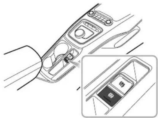
natural_image
Diagram of a car interior showing the dashboard and side view of the backrest door (no text or symbols present)Withthedriver'sseatbeltfastened,thedoorclosedand thepowersystemoperating,presstheautoholdswitchto switchtheautoholdfunctionfromOfftoStandbysstate.
With the brake pedal firmly pressed and the vehicle completely stopped the autohold function will switch from the Standby stat eto the Parking state.
WhentheautoholdisintheParkingstate,engagingDorR andpressingtheacceleratorwillautomaticallyreleasethe autoholdfunction.
I someircumstances such asleasing the belt, switchingoffthepowersystemorremainingstaticfora lengthoftimeitwillresultinthevehicleexitingtheauto holdParkingstatAtthistimetheelectronicparking brakewillremainappliedandwillrequirethedriverto releaseitusingtheswitch.
Note: Whentheautoholdisintheparkingstate, even ifthedriverreleasesthebrakepedal, thepedalwill notreturntoitsinitialposition, itwillremaininthe pressedposition. Whentheautoholdautomatically releasesorexitingtheparkingstateandenablingthe EPB, thebrakepedalwillreturntoitsinitialposition.
Note: With the brake pedal pressed, operating the switch to turn the autoholdoff, the system will NOT apply the parking brake.
Note: It is recommended to turn off the autohold function when reversing into the garage.
EmergencyBrakingHazardWarningLights ControlSystem(HAZ)
Ifthevehicleistravellingathighspeedandthedriver makesanemergencybrakingmanoeuvre,thesystemwill automaticallyflashthebrakelampstowarnthefollowing drivers,therebyeffectivelyreducingtheriskofrear-end collisionaccidents.
Note: If the hazard warning lights are being operated manually, this suspend the HAZ function.
Whentheemergencybrakingmanoeuvreisexited(no severedecelerationdetected)thenthefunctionwillbe switchedoffafterafewseconds.
ElectronicParkingBrake(EPB)

IntheeventofEPBmalfunctionwhereEPB releaseisnotpossible,pleaseconsultanMG AuthorisedRepairerinordertocarryoutan emergencymanualreleaseoftheparking brake.
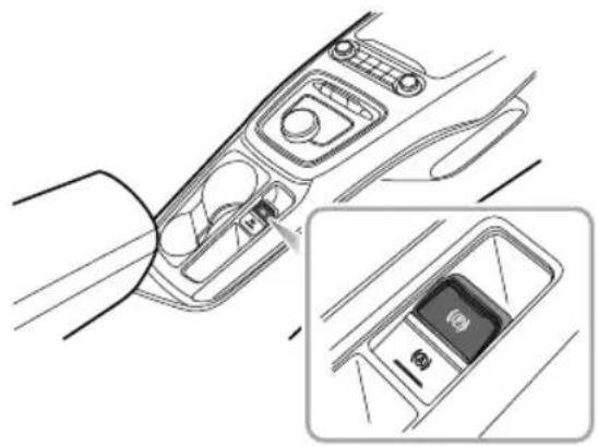
natural_image
Diagram of a car interior showing the left side with handle and seat, and the right side with a close-up of the back panel (no text or symbols)STARTING&DRIVING
ApplyingtheEPB
Whenthevehicleisparkedsafely,selectingPonthe gearshiftcontrolknobwillautomaticallyapplytheEPB. IfautomaticapplicationoftheEPBfails,itisnecessaryto manuallyapplytheparkingbrakeusingtheEPBswitch
- PulltheEPBswitchupwarduntiltheindicatorintheEPB switchilluminates.
- If the indicator lamp in the EPB switch and the indicator lamp (P) in the instrument pack to illuminate, it indicates that the EPB is applied.
• If the EPBMIL (P) in the instrument pack stay on, it indicates that the EPB has a fault. Please contact an MG Authorised Repairer immediately.
Note: Anaudiblemotornois may be heard when applying or releasing the EPB.
IMPORTANT
• DONOTleavethevehiclebeforetheindicatorin EPBswitchilluminatesandthegearindicatordisplays P, thevehiclemaynotbesafelyparkedduetoEPB failureandslip.
• Intheeventofaflatbatteryorpowerfailureitis notpossibletoapplyorreleasetheEPB.Ifusing 'jumpleads'totemporarilysupplypowerpleaseesee 'EmergencyStarting'intheEmergencyInformation.
ReleasingtheEPB
If the vehicle is stably parked on a flat road or slight incline/decline, the vehicle powers system is READ Y, press the brake pedalandus et heshift control system to switch from PtoN, DorR, the EPB will automatically released.
Ifonasteepslope, switching from the P position will not automatically releasethe EPB. In this case, manually release the EP Bas follows or apply the start assist function of the EP B to releasethe EPB.
STARTING&DRIVING
- PlacetheSTART/STOPSwitchintheON/READY position, pressthebrakepedal, and presstheEPB switch;
•TheindicatorintheEPBswitchandtheindicatorlamp (P) intheinstrumentpackareextinguished,theEPBis released.
StartAssist
TheEPBcanpredictthedriver'sintentionand automaticallyreleasetheEPB.
If the driver's seat belt is fastened, the powers system is READY, Dor R gear is selected and the accelerator pedal is pressed in order to pull away, the EPB will automatically release.
EmergencyBrakingFunction

InappropriateuseoftheEPBcanleadto accidentsandinjuries.DonotapplytheEPB forvehiclebraking,unlessinemergency.

During emergency braking using the EPBDO NO Tswitch off the vehicle power system, this could result in serious injury.
In the event of normal brake failure, emergency braking using the EPB can be initiated by pulling and holding the EPB switch upward.
- PullingandholdingtheEPBswitchupwardcanrealize emergencybrakingduringemergencybrakingusing EPB,anaudiblewarningwillsound.
- T ocanceltheemergencybrakingprocess,releasethe EPBswitch.
STARTING&DRIVING
StabilityControlSystem(SCS) and T ractionControlSystem(TCS)
StabilityControlSystem(SCS)
SCSisdesignedtoassistthedriverincontrolofdriving direction. TheSCSautomaticallyentersStandbymode afterthepowersystemisstarted.
WhenSCSdetectsthatthevehicleisnotmovinginthe intendeddirection,itwillintervenebyapplyingbrakeforce toselectedwheelsorthroughthepowermanagement systemtopreventslidingandassistinbringingthecarback totherightdirection.
T ractionControlSystem(TCS)
The purpose of TCSistoaid traction and driving stability, thereby helping the drivertomaintain control of the car. TCS monitor the drivingspeed of each wheel individually. If spin is detected on one wheel, the system automatically brakes that wheel, transferring torque the opposite, non-spinning wheel. If both wheels are spinning, the system will reduce the output torque of the powersystem in order to regulate wheel rotation until traction is regained.
SwitchingOn/Off
SCSandTCSareautomaticallyswitchedonwhenthe START/STOPSwitchplacedintheON/READYposition. Theycanbeswitchedoffbyusingthe"StabilityControl" switchlocatedwithintheinfotainmentsystemdisplay.
WhenSCSandTCSareswitchedoff,Stability Control/T ractionControlSystemOFFWarningLamps inthemessagecentreofinstrumentpackwillilluminate. Referto"WarningLightsandIndicators"in"Instruments andControls"section.
NotDisablingCSandTCSwillaffected the operationofABS.AlwaysdisableSCSandTCSwhen drivingwithsnowchainsfitted.
StabilityControl/TractionControlWarning Lamps
Referto"WarningLightsandIndicators"in"Instruments andControls"section.
T yrePressureMonitoringSystem (TPMS)

TPMScannotreplaceroutinemaintenance andcheckofthetyreconditionorpressure.

Usingequipmentthattransmitson frequenciessimilartothatoftheTPMS mayinterferewiththeoperationofthe TyrePressureMonitoringSystem, thismay illuminateawarningorregisteratemporary fault.
Note: TPMSonlygivesthedriverawarningwhenthe tyrepressureislow, itwillnotinflatethetyre.
TPMSusespressuresensorsbuiltintotyrevalvesto continuouslymonitorpressureandtransmitssignaltoECU insidethevehicleusingRFsignals.Ifitdeducesthatthe pressureofthattyrehasfallenbelowthepredefinedlimit ofthesystem,thewarninglightontheinstrumentpackwill illuminate(alwaysyellow).Formoreinformation,please referto'InstrumentPack'in'InstrumentsandControls'
section.Checkyourtyresattheearliestopportunityand reinflatetothecorrectpressure.Pleasereferto'Tyre Pressure(Cold)'in'T technicalData'section.
SystemMalfunction

Thissystemisself-monitoring,ifamalfunction
isdetected, the TPMSwarninglamp(yellow) on the instrumentpackwillflashfor90secondsfirstandthen remainilluminated.
Note: When apuncture is detected, the system will requires sometime to analyse information prior to illuminating the warning lamp.
Undercertainconditionsthewarninglightmayilluminate whenafaultisnotpresent,theseconditionsinclude: Anonrecommendedtyrefitted(includingsparetyre). Roughterraindrivingforexcessiveperiods. Bendingormountaintypeterraindrivingforexcessive periods. TPMSwillnotrespondimmediatelyifatyre'blowsout'.
STARTING&DRIVING
TPMSSelf-learning
TheTPMSsystemisa'selflearning'system,afterresetting tyrepressuresitwillbenecessarytoallowthesystemto gothroughaselflearningprocess.Thisisdonebydriving thecar,duringthisprocessthesystemissuspendedandthe datadisplayedmaynotbecorrect.Ifsensororreceiver modulearereplacedthesystemrequiresprogramming, consultanMGAuthorisedRepairer .Ifthewheelsare swappedorrotatedthesystemrequiresreprogramming tolearnthenewtransmitterpositions,consultanMG AuthorisedRepairer.
CruiseControlSystem \*

text_image
1 7 3 6 2 4 5•Acceleration(I)
•CruiseResume(5)
•Deceleration(2)
•CruiseSet(6)
• CruiseCancel(3)
•CruiseOFF(7)
•CruiseOn/Standby(4)
Cruisecontrolenablesthedrivertomaintainaconstant roadspeedwithoutusingtheacceleratorpedal. This isparticularlyusefulformotorwaycruising,orforany
journeywhereaconstantspeedcanbemaintainedforalengthyperiod.
CruiseControlSystemActivation
Cruisecontrolsystemisoperatedwithaleverlocatedat theleftsideofthesteeringwheelunderneaththelighting stalkswitch.
IWiththeSTART/STOPSwitchintheON/READY position,iftheleverswitchisinthe'OFF'position (7),thenthecruisecontrolisOFF .Iftheleverswitch isinthe'ON'position(4),thenthesystemisin standby.Pulltheleverswitchtothe'ON'position(4), theyellowindicatorlamp intheinstrumentpack illuminates,indicatingthesystemisin'standy'mode.
With the system in Standby 'wher the current vehicle speeds above 20 mph (30 km/h) pres the Set button (6) at end of the device witch The yellow indicator lamp in the instrument pack will chan get o green and the system will enter the activated state. The targetspeed of the cruises system will beset at the currentspeed, and the cruises system will take effect. At thistime, the cruise control system will maintain
STARTING&DRIVING
thesetspeedwithoutpressingtheacceleratorpedal. Theoperatingrangeofthecruisecontrolsystemis20-100mph(30-160km/h).
Note: Thesetspeedheldinthecruisecontrolmemory willbecancelledwheneitherthecruisecontrollever isswitchedto'OFF'position(7)ortheSTART/STOP Switchturnedoff.
T argetCruiseSpeedAdjustment
Whenthecruise controlisactive:
Pushtheleverupwards(1)andhold,thiswillincrease the speed.Releasetheleverswitchwhenthedesiredspeedis reached.
Pushtheleverdownwards(2)andhold,thiswilldecrease thespeed.Releasetheleverswitchwhenthedesiredspeed isreached.
Pushtheleverswitchupwards(1)ordownwards(2) brieflytoincreaseordecreasethevehicletargetspeed inincrementsoflmph(lkm/h),thevehiclewill accelerate/deceleratetothenewtargetspeed.
Pressingtheacceleratoratanytimewilloverridethecruise controlandallowaccelerationtoundertakemanoeuvres suchasovertakingReleasingtheacceleratorwillreturn thevehicletothesettargetspeed.
Pause/Standby
Cruise control wil belisengaged and etd Standbyif:
LeverswitchmovedoCancelposition(3).
Brakepedalpressed.
ShifControKnobmovedPBoN.
ConditionsinitiateSCSintervention.
Anincline causes excessive decline speed.
TheEPBbuttonisoperated.
Resume
the ruis control emainstedisengagement, movingtheleverswitchthe'Resume'positio(5) willreinstatethetargetspeedtothesettingprior to disengagement.
Note:
Neveusethcruiscontrosystemirreversgear.
STARTING&DRIVING
•DONOTusethecruise controlin unsuitable conditions, such as on slipper surfaces, excessively heavy rain or in traffic condition that donotsuit maintenance of constants speeds.
- Whennotinuse,ensuretheleverswitchisinthe 'OFF'position(7).
- Whenthelectricdrivetransmissionisin'Sport' mode, it is not recommended to set the cruise control system.
- During the operation of the cruise control system, the actual speed may deviate from the target cruise speed to some extent duetoroad conditions (such as uphill, downhill, etc.).
- If the actualspeedis excessively lower than the targetspeedor SCS is activated dueto the hill or roadsurfaces, the cruise control system may automatically revert to Standby mode.
•DONOToperatetheswitchforexcessivelylong periods,orpressmultipleswitchessimultaneously, thismaycausethesystemtofail.Ifthissituation occurs,whenitissafetodoso,cyclethevehicle powersystem.
STARTING&DRIVING
ParkingAid
UltrasonicSensorParkingAid

The purpose of the parking aid to assist the driver in reversing! Thesensors may not be able to detect certainty types of obstruction, e.g. narrow posts or small objects nomore than a few inches wide, small object closet to the ground, objects above the target gate and some objects with nonreflectives surfaces.

Keepthesensorsfreefromdirt,iceandsnow. Ifdepositsbuilduponthesurfaceofthe sensors,theirperformancemaybeimpaired. Whenwashingthecar,avoidaiminghigh pressurewaterjetsdirectlyatthesensors fromcloserange.
RearParkingAid
The ultrasonicsensors in therear bumper monitor the area behind the vehicle to search for obstacles. If an obstruction is detected, the system calculates its distance from therear of the car and communicates this information to the driver by sound warning chimes.
ParkingAidOperation
WhentheSTART/STOPSwitchisintheON/READY position,therearparkingaidisenabledautomatically whenreversegearisselected,itisswitchedoffassoonas reversegearisdisengaged.Ashortbeepisgivenbythe parkingaidwithinl secondafterselectingreversegearto indicatethatthesystemisoperatingnormally.
Note: falonger, higher pitched soundisemitted for 3 seconds when reverse gear is selected, this indicates afaultinthesystem. In this case seek assistance from your MGA authorised Repairer.
With the parking aid function enabled, if an obstruction is detected, the audibles sounds indifferent frequencies are transmitted (theremightbeblind zones).
STARTING&DRIVING
• Ifanobstructionislocatedwithin 1.2mrangeoftherear parkingaidsensors,thewarningcommences.Asthecar movesclosertotheobstruction,theaudiblesoundsare transmittedmorerapidly.
- Oncetheobstructioniswithin30cmrangeoftherear bumper, theaudiblesoundswillmergeintoacontinuous warning.
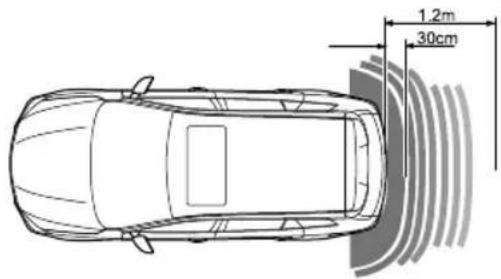
text_image
1.2m 30cmParkingCamera

The purpose of the parking camerasystem is to assist the driver in reversing! The camera has limited field of view and cannot detect obstructions outside the field of view.
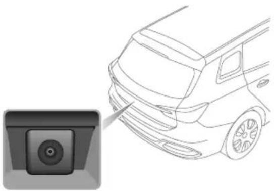
natural_image
Side view of a car with a camera lens icon pointing to the side panel (no text or symbols present)Arearparkingcameraisfittedbetweenthelicenseplate lamps. When reverse gear is selected, the camerawill
STARTING&DRIVING
displayanimageofwhatisimmediatelybehindthecar.This imagewillbeshownontheentertainmentsystemscreen.
Modelsfittedwiththeparkingcamerasystemdisplayan overlaygridonthecameraimageintheentertainment displaytoassistparking,thisissupportedbythesilhouette imageshowingobjectdistancefromeachsensor.
LoadCarrying

DONOTexceedthegrossvehicleweight orthepermittedfrontandrearaxleloads. Failuremayresultinvehicledamageor seriousinjury.
LoadspaceLoading

Ensure that there are seat backrests are securely latched in the upright position when loads are carried in the load space behind theseats.
When luggage is carried in the load space, always ensure heavy items are placed as low and as far forward as possible, so to avoid the cargoshift in the event of an accidentor sudden stop.
Driverefullydoichergenkayaking manoeuvres.
Drivingwiththetailgateopenisverydangerous. If the loadbeingcarriedrequiresthetailgatetobeopen, please ensure the cargo suitably secured.
IMPORTANT
Traffic regulations must be observed via loading cargo, if the cargo extrude the load space appropriate warning measures must be taken to warn other road users.
InternalLoading

DONOT carry unsecured equipment, tools or luggage that could move, causing personal injuries, accidents, emergency braking or hard acceleration.

DONOTobstructthedriver'sorpassenger's visionwithloads.
Foldingtherearseatscanincreaseluggagespace; refer to "RearSeats" described in the "SeatsandRestraints" section.
Whencargoisloadedinthevehicle,placeitataposition aslowaspossibleandensurethatitistightlysecured,soas toavoidpersonalinjurycausedbycargomovementwhen trafficaccidentsoremergencybrakingoccurs.lfthecargo
STARTING&DRIVING
hastobeplacedonaseat, thentheseat must not be used by an occupant during that time.
EmergencyInformation
184HazardWarningDevices
185eCall-SOSEmergencyAssistance
187 EmergencyStarting
190VehicleRecovery
194TyreRepairandWheel
Replacement
201 FuseReplacement
209BulbReplacement
EMERGENCYINFORMATION
HazardWarningDevices
HazardWarningLights

natural_image
Interior view of a car showing the dashboard and steering wheel with a warning sign (no text or symbols on the diagram itself)Note: Before you stop a slow the carinan emergency, always press the hazard warnings switch. All the direction indicators will flash together to warn other road users when your car is causing an obstruction or in a hazardous situation. Remembertoswitch off before driving away.
WarningT riangle
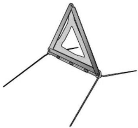
natural_image
3D diagram of a triangular structure with three legs and internal cutouts, no text or symbols presentThewarningtrianglesuppliedwithyourcarisstowedin theloadspace.
If you havetostopy our carontheroadinan emergency, you must place awarning triangle approximately 50-150 metres behind the car, if possible, to warn other road users of your position.
EMERGENCYINFORMATION
eCall-SOSEmergencyAssistance
Inanaccident, your vehicle's eCall–SOSEmergency Assistance can either be triggered manually or in severe cases automatically up on detection by vehicles sensors.
TheeCallserviceisapublicserviceandisaccessiblefree ofcharge.Theemergencycallcentrewillestablishverbal communicationwiththevehicleoccupantsinorderto understandtheextentoftheemergencyandthelevel ofassistancerequired.Ifverbalcommunicationisnot achievableanattemptwillbemadetosendthefollowing vehicleinformationtotheemergencycallcentre.The appropriateemergencyserviceswillbedeployedtothe vehicle'scurrentlocationifknown.
•Currenttime,locationanddirectionoftravel
•Vehicletype
•Vehicleidentificationnumber(VIN)
- Whetherthecallwasautomaticallyormanuallyinitiated
•Vehiclecategory
This system will ensure that your personal data is securely protected. It is designed to ensure that it is not traceable and other external systems are not available. When the
eCalltriggers, thesystemwillonlytransmitthe data informationtotherelevantpublicsafetyansweringpoints designated byrespectivpublicauthorities the countryonwhichterritorytheyarelocated, whichwill receiveandprocessyouremergencycallrequest. The systemwillretainatalocallyfor13hoursaftertriggering.
You havetherighttoaccessthdatainformationstored in this system, and to request the rectification, erasure or blocking of data information that does not meet the requirements of the regulation. When you think your personal data is infringed, you havetherighttocomplain to the competent dataprotection authority.
Formanualactivation, pressandreleasetheSOSbutton theoverheadonsolfeconductivaten emergencyservicescall.Asinglebeepwillbeheardwhen theeCallistriggeredandamessagewillbedisplayedon thevehicle'smessagecentreandentertainmentplayer.The entertainmentplayerwillbemutedwhilsttheemergency servicesaktManuallyrigeredemergency servicecallsmaybecancelledbypassingandreleasing theSOSbuttonagainwithin5secondsoftheinitialpress, twobeepswillbeheardconfirmingthattheemergency
EMERGENCYINFORMATION
servicescallhasbeencancelledandthemessageswillbe removed.
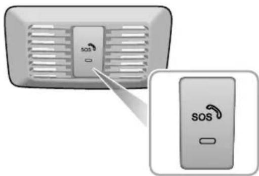
text_image
SOS SOSTheemergencyservicescall(eCall)systemwillperform aself-testwhenthevehiclepowersystemisON.During aSelf-T esttheemergencyservicescall(eCall)LEDstatus indicatorontheSOSbuttonwillflashquicklyuntil completion.TheLEDstatusindicatorwillbeilluminated solidifnosystemfaultsarepresent.TheLEDstatus indicatorwillnotilluminateorflashslowlyifafaultis
detected. Faultsdetectedduringtheself-testwillbe displayedonthevehiclesmessagecentre.
Note: The operation of Call-SOSEmergency Assistancer lies on cellular coverage and maybe affected by signal outages or low signal strength.
Note: The automatic emergency services call (eCall) function may be disabled by the local MGA authorised Repairer upon request.
EMERGENCYINFORMATION
EmergencyStarting
UsingBoosterCables

NEVERattempttopowerthevehicleby pushingortowing.

Makesurethatbothbatteriesareofthesame ratedvoltage(12volts),andthatthebooster cablesareapprovedforusewith12voltcar batteries.

Ensuresparksandnakedflamesarekeptwell awayfromthefrontcompartment.
Usingboostercables(jumpleads)fromadonorbattery, orabatteryfittedtoadonorvehicle,istheonlyapproved methodofpoweringacarwithaflatbattery.
If the battery from adonor vehicle is to be used, makes sure that the vehicles are parked so that the two batteries are adjacent to one another and that both the vehicles donot touch.
StartingtheCar

Ensure that each boostercable connection is securely made. Theremust benorisk of the clips accidentally slipping from the battery terminals, this could cause sparking, which could lead to fire ore explosion.
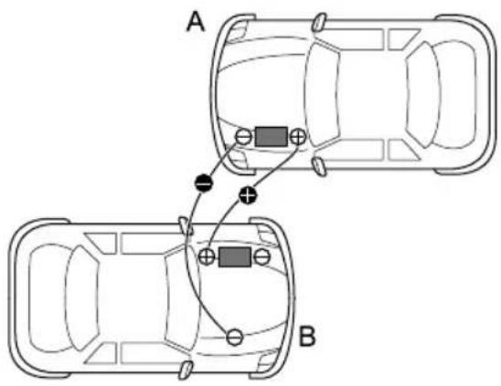
text_image
A BEMERGENCYINFORMATION
EnsuretheSTART/STOPSwitchisturnedoffandswitch offALLelectricalequipmentofBOTHvehicles,thenfollow theinstructionsbelow:
I ConnecttheREDboostercablebetweenthepositive (+)terminalsofbothbatteries. ConnecttheBLACK boostercablefromthenegative(-)terminalofthe donorbattery(A)toagoodearthpoint(theCCU mountingorotherunpaintedsurface,forexample),as farawayfromthebatteryaspossibleandwellaway frombrakelinesonthedisabledvehicle(B).
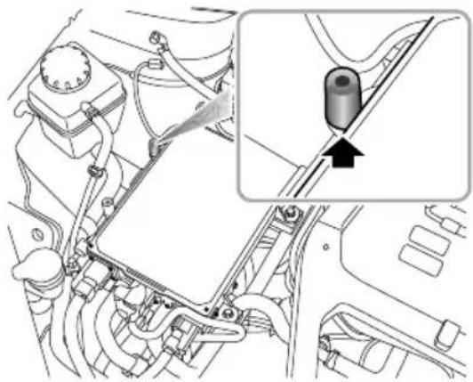
natural_image
Technical diagram of a vehicle engine compartment with a close-up inset showing a component (no text or symbols present)2Startthedonorvehicleandallowittorunforafew minutes.
3Nowswitchthevehiclepowersystemofthevehicle withthedischargedbatterytoREAD Y .Ifthedisabled vehiclewillnotswitchtoREADYitmayneedtobe repaired.PleasecontactanMGAuthorisedRepairer.
4Afterboththevehicleshavenormally started/powered,leavethevehiclesconnectedinthis
EMERGENCYINFORMATION
stateformorethan2minutesbeforeswitchoffthe donorvehicleanddisconnectingtheboostercables.
IMPORTANT
DONOTswitchonanyelectricalapplianceinthe disabledvehicleuntiltheboostercableshavebeen disconnected.
5Disconnectingtheboostercablesmustbeanexact reversaloftheprocedureusedtoconnectthem,i.e. disconnecttheBLACKcablefromtheearthpointon thedisabledvehicleFIRST .
Note: It is recommended to ensure that the disabled vehicler remains powered or runs more than 1 hour afteritis started, in order to recover the battery power.
EMERGENCYINFORMATION
VehicleRecovery
T owingV ehicle

Whenpushingortowingthevehicleontothetransporter,thespeedmustremainbelow3mph(5km/h) andbecompletedwithin3minutes.

Whenpushingortowingthevehicleontothetransporter,thedriver'ssideseatbeltshouldbeinserted intothelockandmaintainedintheinsertedstateinordertoreleasetheEPB.
T owingHook

DONOTuseatowropethatistwisted-orthetowinghookmaybeunscrewed.

DONOTtowthevehiclewiththedrivenfrontwheelsincontactwiththeroadsurface.
EMERGENCYINFORMATION
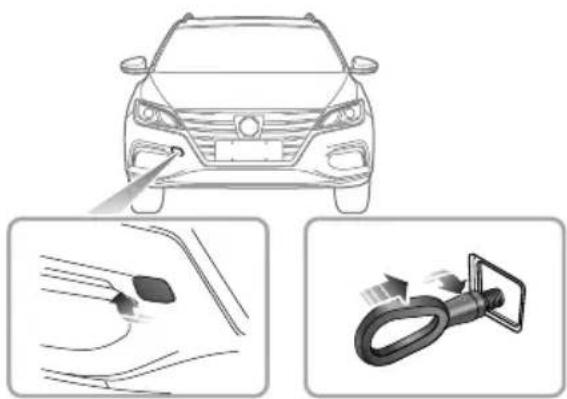
natural_image
Top-down illustration of a car head with a close-up of the front wheel and a close-up of a car's steering wheel (no text or symbols)
natural_image
Illustration showing a car head with a tool interacting with a car surface and a close-up of the handle (no text or symbols)Y ourcarisequippedwith2towingeyes(locatedatthefrontandtherearofthevehicle),whichareusedforfittingthe towinghookinthetoolkit.Thetoolkitisplacedbeneaththeloadspacefloor.
T ofitthetowinghook,removethesmallcoversetintothebumper,thenscrewthetowinghookviathesmallholeintothethreadedholeinthebumperbeam(seeillustration).Ensurethetowinghookisfullytightened!
Note: Thetowingeyecovermaybesecuredtothebumperbyaplasticcord.
Bothtowingpointsareintendedforusebyqualifiedrecoveryspecialiststoassistintherecoveryofyourcarwhenabreakdownoraccidentoccur .Theyarenotdesignedfortowingothervehicles,andmustNEVERbeusedtotowatrailerorcaravan.
EMERGENCYINFORMATION
T owingforRecovery

If, duetoanelectrical fault, potential safety hazards may exist, please ensure the vehicle powersystem miss switched OFF.

Whentowing, DONOTaccelerateorbrake suddenly, this can cause accidents.

DONOTtowthevehiclewithall4wheelsin contactwiththeroad,thiswillcausedamage totheelectricdrivetransmission.
SuspendedT owing

Whenusingsuspendedtowing, be careful not tolet the high voltage battery pack touch the ground.
Suspendedtowingisthebestmethodforvehiclethat needstobetowed. ThedrivenwheelsMUST besuspended abovetheground, thisistoavoidanydamagetoelectric drivetransmissionandpossibleinadvertentpoweringof
thevehicle.EnsuretheEPBisreleased,thehazardlamps areONandnopassengersareinthevehicle.
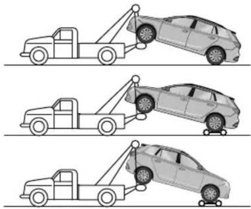
natural_image
Three line drawings of a car being towed from a pole, showing different collision scenarios (no text or symbols)EMERGENCYINFORMATION
T ransporterorT railerwithRope
If your caristobetransported on the back of a trailer or transporter, it must be secured as illustrated:
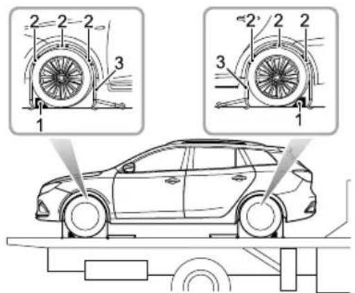
text_image
Technical diagram showing car wheel assembly with numbered components and a supporting vehicle belowI Apply the parking brake and placethe electric drive transmission in park.
2Fitwheelchocks(1)asshown,thenpositiontheanti sliprubberblocks(2)aroundthecircumferenceofthe tyre.
3Fitthelashingstraps(3)aroundthewheelsandsecure tothetrailer.Tightenthestrapsuntilthecaris securelyheld.
EMERGENCYINFORMATION
T yreRepairandWheelReplacement
T oolldentification
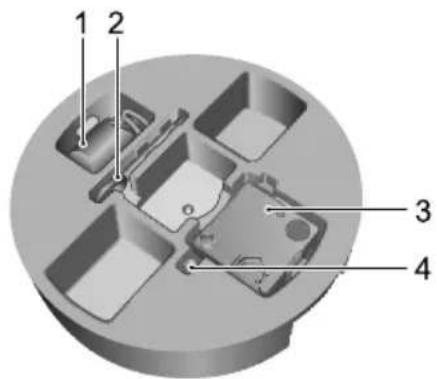
text_image
1 2 3 4I RepairFluidReservoir
2T owingHook
3ElectricAirPump
4WheelBoltCapRemovalTool
T yreRepair
I Removethelabelatthebottomoftherepairfluid reservoirandattachittothesteeringwheeltoremind thedrivernottoexceed50mph(80km/h).
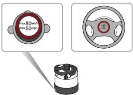
text_image
max80km/h max50mph2Connecttheairhoseoftheelectricairpumpto therepairfluidreservoir,fitthetyresealantbottle (upright)intotheslotonthecompressor.Remove thevalvedustcapoftheflattyre,andconnectthe fillerhosefromthetyresealantbottletothetyre
EMERGENCYINFORMATION
valve.Ensurethatthepowerswitchoftheelectric aircompressorisswitchedoff(i.e.,press“O”),then inserttheplugfromthecompressorintothecentre consolepowersocket,andturnthevehiclepower systemtoON/READY.
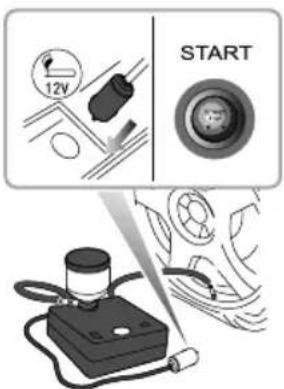
text_image
12V STARTNote: To avoid battery discharges, recommended to keep the vehicle and READY mode.
Switch the powers switch the electric compressor (i.e press-") start pumping a laint the tyre. Thetyresealant bottle will become empty after approximately 30 seconds. Thetyreshould reach the specified pressure within 5 or 10 minutes.
Not the pressure gaugemaybrieflyreach6 bar(87psi), thenthe pressure beginstodropto normal.
When therequire pressures are each switch of the powerswitch of the electric compressor (i.e., press "O").
Nafrequirpressurannbe reachedwithin 10minutes, pleasedisconnectthe compressor, drivethevehicle 10metres(33feet) approxforwardorbackwardtoallowthesealant tospreadwithinthetyre. Iftherequiredpressure castilltreachedtheyneverely damagedandyoushouldeekassistancefromthe MGAuthorisedRepairer.
EMERGENCYINFORMATION
Note: Consecutive operation of Electric air compressor for more than 10 minutes may result in damaggetothecompressor.
Note: Undernocircumstances should you continue your journey with a deflated tyre. Driving vehicle with a deflated tyre is extremely dangerous.
5Removethetyresealantbottlefromtheslotinthe compressor, disconnect the hose fromthetyre valve, removethe compressor plug from the centre console powersocket, returnthetyrerepair kitto its stowage tray.
6Pleasedrivethevehiclewithinoneminuteafter completingtheaboveoperations,sothatthesealantis evenlydistributedinthetyre.PleaseDONOTdrive exceed50mph(80km/h).
Please take different measures based they're pressure measured:
Ifthetyrepressurehasdroppedtolessthan0.8bar (11.6psi),donotcontinuedriving,seekassistance instead.
Ifthetyrepressureisbetween0.8bar(11.6psi)and specifiedpressure,connectthehoseofelectricairpumptothetyrevalve,andconnecttheplugoftheelectricairpumptothepowersocket,thenswitchon theelectricairpumptoinflatethetyreuntilreaches thespecifiedpressure.Repeattheoperationsofstep 6afterdrivingamaximumdistanceof3miles(5km).
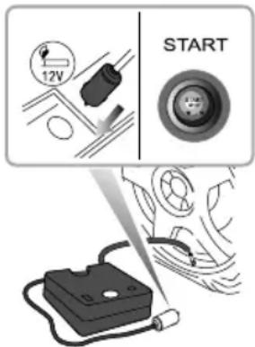
text_image
12V STARTIfthetyrepressurehasnotdropped,youmaycontinue driving,butthevehiclespeedmustnotexceed50mph
EMERGENCYINFORMATION
(80km/h), and the driving mileagemust not exceed 125 miles (200km).
Note: DONOTremoveforeignobjects(eg. screws, nails) from the theyre. Thetyrerepair system must only be used when the foreign object is in the tread pattern(A), DONOT attempt are pair when the damage is in the sidewall of the theyre(B).
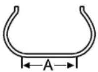
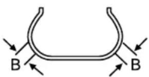
text_image
B BChangingaWheel \*
Ifyouneedtochangethewheelduringthejourney,choose asafeplacetostopawayfromthemainroadifpossible. Alwaysaskyourpassengerstogetoutofthecarandwait inasafeareaawayfromothertraffic.
Switchonhazardwarninglampfavailable,position awarningtriangleabout50to150metresbehindyour vehicletowarnapproachingtraffic.
Beforechangingwheel,ensurethefrontwheelsareinthe straightaheadposition.Applytheparkingbrakeandplace theshiftcontrolknobintheNposition.
Observethefollowingprecautions:
- Ensurethejackispositionedonfirm,levelground.
- Ifthevehiclemustbeparkedonthehill,placechocks infrontofandbehindother3wheelstoppreventthe vehiclemoving.
PositioningtheJack

NEVERworkbeneaththecarwiththejack astheonlymeansofsupportthejackis designedforwheelchangingonly!
EMERGENCYINFORMATION

NEVERjackthecarusinganyareasother thanthedesignatedjackingpoints.Serious damagetothecarcouldresult.
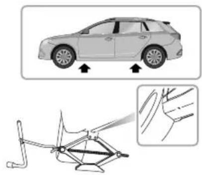
natural_image
Diagram showing a car with directional arrows and a mechanical linkage mechanism, no text or symbols present.
Avoidaccidentalcontactwithanyunderbody parts,especiallyhighvoltagecomponents.
Positionthejackonfirmlevelgroundunderthejacking pointnearestthewheeltoberemoved. Notethatthe
domedheadofthejackmustfitintothecorresponding recessinthesillplate(Thereisatriangleindicatorinthe areashownbythearrowhead.Seetheillustrationabove).
T urningthejackscrewbyhand,adjustthejackuntilthejack headfitssnuglyontothesillinthecorrectarea.Ensurethat thebaseofthejackisinfullcontactwiththelevelground.
FittingtheSpareWheel

Regularlycheckthesparewheeltyre pressure, it maybe used for long periodsoftmax after fitment, at the first opportunit checked adjustyre pressure.

Thewhedoltnusbightenedthe specifiedtorqueafterchangingawheel (115 ≈ 125Nm).
Before raising the car , usethespecial tools supplied with the vehicle to remove each wheel bolt cap. Use the wheel bolt spannertoslackeneach bolthalfaturn anti-clockwise.
EMERGENCYINFORMATION
2T urnthehandleinaclockwisedirectionuntilthetyre isclearoftheground.
3Removethewheelboltsandplacetheminthetooltray topreventthemfrombeinglost.Makesurethevehicle issteadyandthereisnoriskofslipormovement beforeremovingwheelbolts.
4Removetheroadwheel.
Note: Avoidplacingwheelsfacedownonthe ground-thesurfacemaybescratched.
5Fitthesparewheelandtightenthewheelboltswith wheelboltspanneruntilthewheelisseatedfirmly againstthehub.
6Lowerthecarandremovethejack, thenFULLYtighten thewheelboltsinadiagonalsequence.
7Finally, return the tool to the toolbox, put the toolbox into theellofthe bootfloor, tightenthesparewheel retaining nuts, and put there placed wheel above the toolbox in the well in the load space floor (facedown). Lower the bootfloor, and put the boot storage box on the bootfloor.
Note: DONOT standon the handle of the wheel bolt spanner or use extension tube on the handle of the spanner.
Note: When replacing the wheel, please fully tighten the bolts in the diagonal sequence twice.
Note: ConsultyourMGAuthorisedRepairer.ortyre specialistforareplacementtyre, as soon as possible.
SpacesaverSpareWheel

Onlyonespacesaversparewheelcanbeused atanyonetime,otherwisetheoperational performanceandbrakeperformancemaybe reduced,therebyleadingtoaccidentorinjury toyourselfandothers.

Whendrivingonicyorslippery surfacesitis advised to fit the spacesaverwheel to therear of the vehicle to maintain a quatestability. This may means swapping a front wheel with arear wheel.
EMERGENCYINFORMATION

Snowchains cannot be used on the spacesaversparewheel, this can cause damagetothecarandsnowchain.
Whenthespacesaversparewheelisfitted,thevehicle speedshouldnotexceed50mph(80km/h).Pleasehave thefull-sizetyrerepairedandreplacethesparewheelas soonaspossible.Thiswillextendthelifespanofthespare wheelforotheremergencies.
Note: DONOTuseanautomaticcarwashwhen thespacesaverwheelisfitted, theguiderailsofthe carwashmayconflictwiththewheel/tyreandcause damage.
EMERGENCYINFORMATION
FuseReplacement
Fuse
Fusesaresimplecircuitbreakerswhichprotectthecar's electricalequipmentbypreventingtheelectricalcircuits frombeingoverloaded.Ablownfusemaybeindicated whentheitemofelectricalequipmentitprotectsstops working.
Ifyoususpectafuseitcanbecheckedbyremovingitfrom thefuseboxandlookingforabreakinthewireinsidethe fuse.
It is recommended to have spare functions in the vehicle, which can be obtained from local MGA authorised repairer.
IMPORTANT
- NEVERattempttorepairablownfuse.ALWA YS replaceafusewithoneofthesamerating,failureto usethecorrectlyratedfusecouldresultinafireor electricalcircuitdamageduetooverloading.
• Ifareplacedfusefailsimmediately, pleasecontactan MGAuthorisedRepairerassoonaspossible.
FuseBox
Thevehicleisequippedwith2fuseboxes:
- Passengercompartmentfusebox(behindthedriver sidelowertrimpanel)
- Frontcompartmentfusebox(frontleftofthefront compartment)
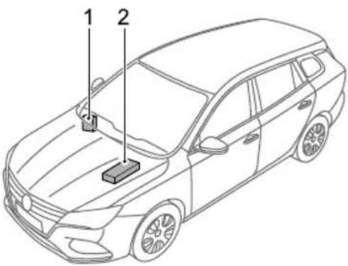
text_image
Technical diagram of a car with labeled parts 1 and 2, showing front and side views.I Passengercompartmentfusebox
2Frontcompartmentfusebox
EMERGENCYINFORMATION
PassengerCompartmentFuseBox
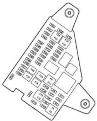
text_image
Technical diagram of a vehicle rear panel with labeled components and mounting pointsCheckorReplaceaFuse
IT urnofftheStart/StopSwitchandallelectrical appliances, and disconnectthenegativebatterycable.
2Removethedriversidedashboardendcoverplate and lowertrimpaneltoaccessthefusebox.
3Checkasuspectfusebyremovingitfromthefusebox andlookingforabreakinthewireinsidethefuse.
4lfafuseisblown, replaceitwithanotherfuseofthe sametypeandsameamperevalue.
FuseSpecification
| CodeSpecs | Function | ||
| F1 | 15A | FrontConsolePower Socket | |
| 5A | F2 | InterMirr &ear Consol UCBarging Ports | |
| F3-F17 | - | - | |
| 5A | F18 | TBOXehiControl UnSensingDiagnostic Module(Airbag hifter Control Unit,Instrument Pack | |
| ACB | AntP419 | ||
EMERGENCYINFORMATION
| CodeSpecs | Function | |
| F2010AA | CControlModule | |
| F2110AF | rontRightSeat | Heater |
| F225AD | agnosticSocket | |
| F2310AF | frontLeftSeat | Heater |
| F245APE | PSControlModule | |
| F25 | - | - |
| F2630A | FrontLeftWindowLift,RearRightWindowLift | |
| F27 | - | - |
| F285AB | ckupImmobilizerCoil | |
| F2915AE | entertainmentSystem | |
| F305A | InstrumentPack | |
| F315AEP | BSwitch | |
| F325ARai | nLightSensor | |
| CodeSpecs | Function | |
| F3310A | SensingDiagnosticModule (Airbag) | |
| F3410A | DriverDoorSwitchPack, Gateway | |
| F35-F36 | - | - |
| F3725A | DriverElectricSeat Adjustment | |
| F38 | - | - |
| F3940A | Blower | |
| F40-F43 | - | - |
| F445A | Radiating ReceptionModule | |
| F4510A | Electronic ColumnLock | |
| F46 | - | - |
EMERGENCYINFORMATION
| CodeSpecs | Function | |
| F475A | HighVoltageElectric Heater | |
| F48 | - | - |
| F495ATBOX | ||
| F5010AG | gateway | |
| F51 | 5A | ShifterControlUnit, T yrePressureMonitoring System |
| F525A | DoorMirrorsand HeadlampLevelling AdjustmentSwitch | |
| F535A | PedestrianAleControl Module | |
| F54 | - | - |
FrontCompartmentFuseBox
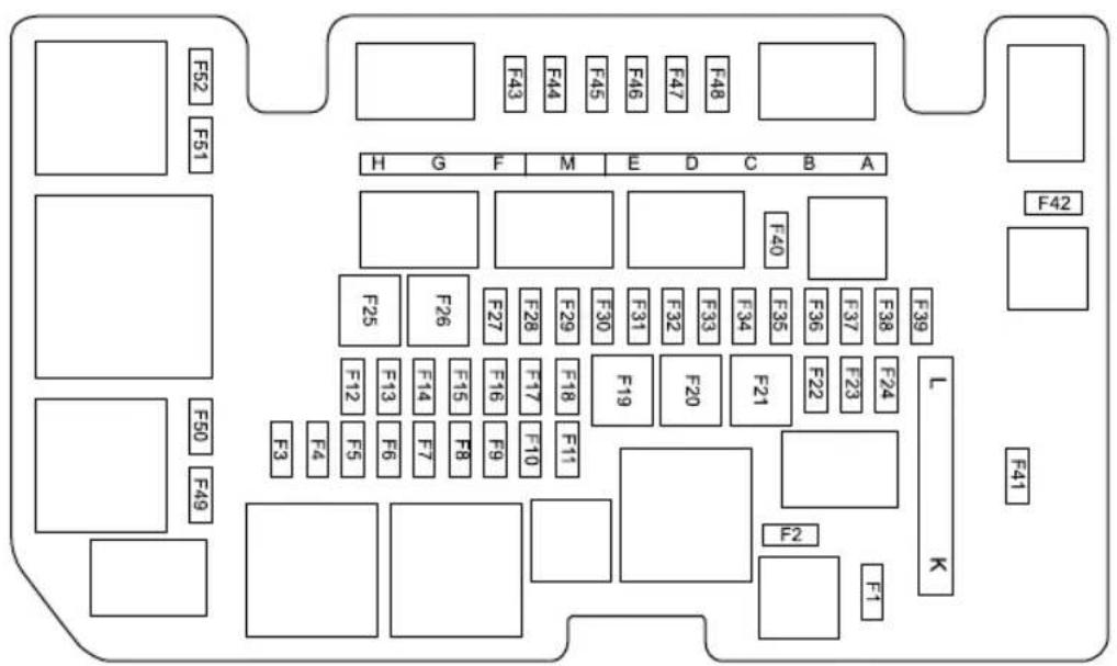
text_image
F52 F51 F43 F44 F45 F46 F47 F48 H G F M E D C B A F40 F25 F26 F27 F28 F29 F30 F31 F32 F33 F34 F35 F36 F37 F38 F39 F12 F13 F14 F15 F16 F17 F18 F19 F20 F21 F22 F23 F24 L K F30 F10 F11 F8 F9 F12 F5 F6 F7 F3 F4 F2 F1EMERGENCYINFORMATION
CheckorReplaceaFuse
IT urnofftheStart/StopSwitchandallelectrical appliances, and disconnect thenegative batterycable.
2Pressthelockcatchtoopentheuppercoveroffront compartmentfusebox.
3Checkasuspectfusebyremovingitfromthefusebox andlookingforabreakinthewireinsidethefuse.
4lfafuseisblown, replaceitwithanotherfuseofthe sametypeandsameamperevalue.
FuseSpecification
| CodeSpecs | Function | |
| F1 | 120 | On-boardNetworkT erminal Resistance |
| F2120Ω | On-boardNetworkT erminal Resistance | |
| F330ABodyControl | Module | |
| F420ABodyControl | Module | |
| CodeSpecs | Function | |
| F5 | 15A | BodyControlModule |
| E65Aging | PlugLatch | |
| F7 | Vehicle | ControlUnit |
| F830A | EledRaidNugorControlUnit | |
| F915A | HornRelay,Horn | |
| F10 | - | |
| F11 | 15A | HighVoBatteryPlacVehicleCommunicationController,BatteryHeater |
| F12-F24 | - | |
| 30A F25 | DriverDockSwitchPack,DriveWindowLift,RearLeftWindowLift |
EMERGENCYINFORMATION
| CodeSpecs | Function | |
| F2630A | StabilityControlSystem(Valve) | |
| F2715AW | Windscreen | WasherSystem |
| F2810AB | BodyControl | Module |
| F2920AB | BodyControl | Module |
| F3025AF | FrontWiper | System |
| F3110A | PowerElectronicBox | |
| F3225AB | BodyControl | Module |
| F3320AS | Superlock | System |
| F3415A | Mainrelay,PowerElectronicBoxWaterPump,BrakeLampSwitch | |
| F355AC | combinedCh | argingUnit |
| CodeSpecs | Function | |
| F365A | ElectricAirConditioning Compressor | |
| F3710A | MainBeamRelay,Mainbeam | |
| F3815ARearWiperSystem | ||
| F3915A | High—VoltagBatterPack CoolantPump | |
| F40-F42 | - | |
| 7.5A F43 | HeatedExterioRearview Mirror | |
| F4425A | HeatedRearWindow | |
| F45 | - | |
| F465A | DoorMirrorsandHeadlamp LevellingAdjustmentSwitch, ManualHeadlampLevelling | |
| F47 | - | |
EMERGENCYINFORMATION
| CodeSpecs | Function | |
| F485AChargingFlapMotor | ||
| F49-F52 | - | |
| FUSEA80A | ElectricPowerSteering Module | |
| FUSEB | - | |
| FUSEC40A | StabilityControlSystem (Pump) | |
| FUSED | - | |
| FUSEE | - | |
| FUSEF30A | ElectricalParkingBrake ControlModule | |
| FUSEG50ACoolingFan | ||
| FUSEH50A | iBooster | |
| FUSEM150CombinedChargingUnit | ||
| CodeSpecs | Function | |
| FUSEL30A | ElectroParkBrakeControlModule | |
| FUSEK100A | PassagepartmentFuseBox |
BulbReplacement
BulbSpecification
| Bulb | Specifications |
| HeadlampHigh/Low Beam | HB360W |
| FrontDirection Indicators | WY2IW2IW |
| ReverseLamps | W16W16W |
| StopLampsW2IW2 | IW |
| Bulb | Specifications |
| LicensePlateLampsW5W | W5W |
| RearDirectionIndicators | WY16W16W |
| FrontCourtesyLamps | W5W5W |
Note: Other lightsources not included in the list are LED, which cannot be replaced individually.
EMERGENCYINFORMATION
BulbReplacement
Beforereplacinganybulb,turnofftheSTART/STOPSwitch andlightingswitchtoavoidanypossibilityofashortcircuit.
Note: Only replace bulb with the sametype and specification.
If the bulbglassisscratchedorcontaminated, it may mean the bulbcannotconcentratethelight. Take care NOT to touch the glass with your fingers; If necessary, clean the glass with methylated spirit store move fingerprints.
ConsultanMGAuthorisedRepaireronspecific replacementoperation.
High/LowBeamBulbRenewal
I Openthebonnet——see "Bonnetthe "Maintenance" section.
2Disconnectthebatterynegativeterminal.
3Remove 10screwsfixingthefrontcompartmenttrim covertothebody,andremovethefrontcompartment trimcover.
4Identifyandlocatethehigh/lowbeambulbcoverplug. Rotatethecoveranti-clockwiseandremovethecover plug.
EMERGENCYINFORMATION
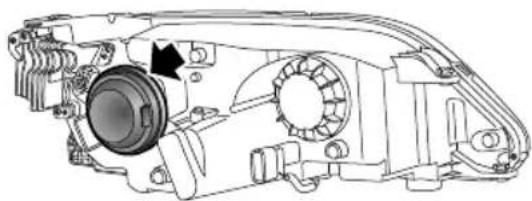
natural_image
Technical line drawing of a mechanical assembly with no visible text or symbols10Connectthenegativebatteryterminal.
IIT estlampoperation.
12Refitthefrontcompartmenttrimcovertothebody.
13Closethebonnet——see“Bonnet”inthe “Maintenance”section.
5Rotatethebulbanti-clockwiseandremove.
6Removethewiringconnectorfromthebulb.
7Refitthewiringconnectortothenewbulb.
8Locatethebulbholderinthelamp,rotateclockwise untilfullysecured.
9Refitthebulbcoverplug, rotateclockwiseuntilfully secure.
EMERGENCYINFORMATION
FrontDirectionIndicatorsBulbRenewal
I Openthebonnet——see "Bonnet" in the "Maintenance" section.
2Disconnectthebatterynegativeterminal.
3Remove 10screwsfixingthefrontcompartmenttrim covertothebody,andremovethefrontcompartment trimcover.
4Identifyandlocatethebulbcoverplug.Rotatethe coveranti-clockwiseandremovethecoverplug.
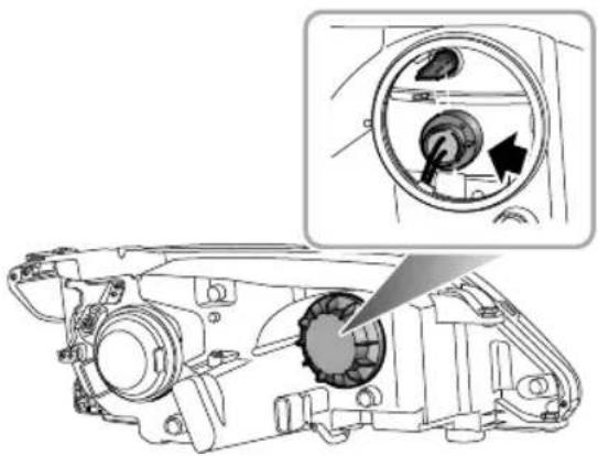
natural_image
Technical diagram of a mechanical component with an inset showing a circular dial and a knob (no text or symbols present)5Removethebulbholderfromthelampunit.Remove thebulb.
6Fitnewbulb.Locatethebulbholderinthelamp assembly,ensureitisfullysecured.
7Locatethebulbcover ,rotateclockwiseuntilfully secure.
8Connectthenegativebatteryterminal.
EMERGENCYINFORMATION
9T estlampoperation.
10Refitthefrontcompartmenttrimcovertothebody.
IIClosethebonnet——see“Bonnet”inthe “Maintenance”section.
ReverseLampsBulbRenewal
I Disconnect the battery negative terminal.
2Openthetailgate.
3Usingasuitableprybarorlever,carefullyremovethe covertrim.
4Rotatethebulbholderanti-clockwiseandremovethe bulbfromholder.
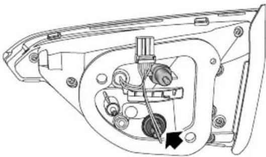
natural_image
Technical line drawing of a mechanical assembly with no visible text or symbolsEMERGENCYINFORMATION
5Fitthenewbulbintotheholder.
6Insertbulbholderinlampassembly, rotateclockwise untilfullysecure.
7Connectthenegativebatteryterminal.
8T estlampoperation.
9Refitthecovertrim.
10Closetailgate.
StopLampsBulbRenewal
I Disconnect the battery negative terminal.
2Openthetailgate.
3Usingasuitableprybarorlever,carefullyreleaseand removethesecuringscrewcovertrim.
4Removethe2screwssecuringthelamptothebody.
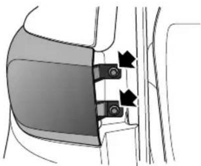
natural_image
Diagram of a car seatbelt mechanism with arrows indicating movement or force (no text or symbols present)5Releasethelampfromthefrontfixingandwithdraw frombody,disconnectthewiringconnector.
6Rotatethebulbholderinananti-clockwisedirection.
EMERGENCYINFORMATION
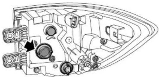
natural_image
Technical line drawing of a mechanical assembly with gears and housing (no text or symbols)I I Refitscrewcovertrim.
12Reconnectbatterynegativeterminal.
13T estlampoperation.
14Closetailgate.
7Removebulbholderandremovebulb.
8Fitnewbulbtobulbholder.
9Insertbulbholderinlampassembly, rotateclockwise untilfullysecure.
10Reconnectthewiringconnector ,positionthelampto thebody,ensurethefrontretainingclipisalignedand fullylocated.Pushthelampforwardstolocateinthe clip.Fitscrewsandtightento2.7-3.3Nm.
EMERGENCYINFORMATION
LicensePlateLampsBulbRenewal
I Disconnect the battery negative terminal.
2Openthetailgate.
3Usingasuitabletool, carefullyremovethetailgate lowerpanelretainingscrewcovers,andremove2 screwsfixingthetailgatelowertrimpanelassembly tothetailgate.
4Usingasuitableprybar,releasethetailgatesecuring clipsandremovethetailgatetrim.
5Carefullyleverthelampoutoftheaperture.
6Releasethebulbfromthebulbholder.
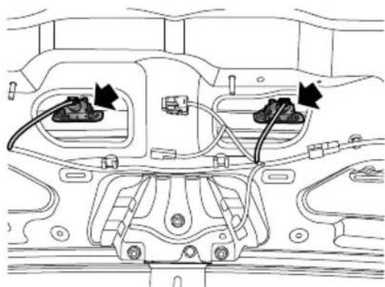
natural_image
Technical diagram of a vehicle engine bay with two sensors and wiring (no text or labels)7Insertthenewbulbinthelampbulbholder.
8Positionthelampinthetailgate,andpushuntilfully secured.
9Positionthetailgatetrimtoaligntheclips, gentlytap thetrimtowardthetailgatetoensuretheclipsare fullylocatedsecureandrefit2screwsfixingthetailgate lowertrimpanelassemblytothetailgate.
EMERGENCYINFORMATION
10Refitthelowertailgatetrimpanelretainingscrew covers.
I IReconnectbatterynegativeterminal.
12T estlampoperation.
13Closetailgate.
RearDirectionIndicatorsBulbRenewal
I Disconnect the battery negativeterminal.
2Openthetailgate.
3Usingasuitableprybarorlever,carefullyreleaseand
removethesecuringscrewcovertrim.
4Usingasuitable10mmspanner/socketwrench, removethe2screwssecuringthelamptothebody.
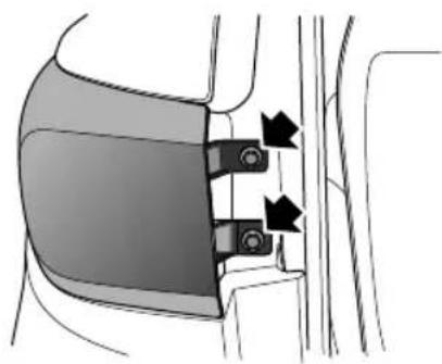
natural_image
Diagram of a car seatbelt mechanism with directional arrows indicating movement (no text or labels)5Releasethelampfromthefrontfixingandwithdraw frombody,disconnectthewiringconnector.
6Rotatethebulbholderinananti-clockwisedirection.
EMERGENCYINFORMATION
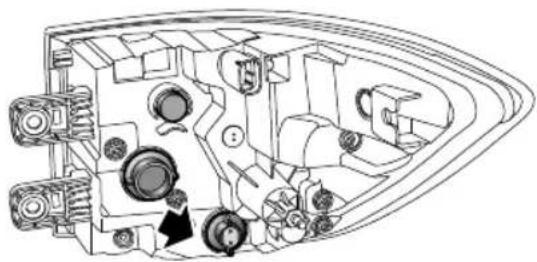
natural_image
Technical line drawing of a mechanical assembly with gears and housing (no text or symbols)7Removebulbholderandremovebulb.
8Fitnewbulbtobulbholder.
9Insertbulbholderinlampassembly, rotateclockwise untilfullysecure.
10Reconnectthewiringconnector ,positionthelampto thebody,ensurethefrontretainingclipisalignedand fullylocated.Pushthelampforwardstolocateinthe clip.Fitscrewsandtightento2.7-3.3Nm.
I I Refitscrewcovertrim.
12Reconnectbatterynegativeterminal.
13T estlampoperation.
14Closetailgate.
EMERGENCYINFORMATION
FrontInteriorLampBulbRenewal

natural_image
Interior view of a car dashboard with control panel and door handle (no text or symbols visible)I Disconnect the battery negative terminal.
2Useasmallflat-bladedscrewdrivertogentlyprisethe lensfromthelampassembly.
3Pullthebulbfromitsmountingtoremove.
Installationofthebulbisareversaloftheremovalprocess. Wheninstallingthelens,locatethetwoprongsatthefront ofthelensandthencarefullyflexthelenstolocatethetwo prongsattherearofthelensintothelampassembly.Push thelensupwardsuntil‘clicks’intoposition.
Maintenance
222Maintenance
225Bonnet
227 FrontCompartment
228CoolingSystem
231 Brake
233 Battery
235HighVoltageBatteryPack
237Washer
239Wipers
242 Tyre
248CleaningandVehicleCare
MAINTENANCE
Maintenance
RoutineServicing
Thesafety, reliability and performance of your car will depend partly on how well it is maintained. You must ensure that maintenance is carried out when required and according to the information contained in the "Service Schedule"-seewww.mg.co.uk-owners section.
Servicing
Firnextserviceinformationpleaseconsultyourservice records.
SomemarketsfeatureaservicereminderinthelPK messagecentre.
ServiceHistory
EnsureMGAuthorisedRepairerregisterstheService Historyaftereachservice.
BrakeFluidReplacement
Replacethebrakefluidaccordingtotheinformation containedinthe"ServiceSchedule"-seewww.mg.co.uk-ownerssection.
Note: Brakefluidreplacementwillbeanadditional cost.
CoolantReplacement
Thecoolant(anti-freezeandwatersolution)needstobe replacedaccordingtotheinformationcontainedinthe "ServiceSchedule"-seewww.mg.co.uk-ownerssection.
Note: Coolantreplacementwillbeanadditionalcost.
OwnerMaintenance

Anysignificantorsuddendropinfluidlevels, oruneventyrewear,shouldbereported withoutdelaytoMGAuthorisedRepairer.
In addition to other routines services referred to previously, an number of simple checks must be carried out more frequently. Advice is given on the page that follows.
DailyCheck
•Operationoflights,horn,wipers,washersandwarning lamps.
•Operationofseatbeltsandbrakes.
- Lookforfluiddepositsunderneaththecarthatmight indicatealeak.
- Checktyreappearance.
WeeklyCheck
•Coolantlevels.
- Brakefluidlevel.
•Windscreenwasherfluidlevel.
- Operateairconditioning.
SpecialOperatingConditions
If your car is frequently used industry conditions, or operated in extreme climates where sub-zero or very high ambient temperatures are normal, more frequent attention may need to be paid to servicing requirements. You need to carry out special maintenance operations (refertoService Schedule) or contact an MGA authorised Repairer.
SafetyintheGarage

Coolingfansmaycommenceoperatingafter thevehicleisswitchedoff,andcontinue operatingforanumberofminutes.Keep clearofallfanwhileworkingthefront motorcompartment
If you need to carry out maintenance, observ the following safety precautions at all times:
- Ifthecarhasbeendrivenrecently,DONOTTOUCH coolingsystemcomponentsuntilthedrivemotorhas beenfullycooleddown.
MAINTENANCE
•DONOTTOUCHelectricalleadsorcomponents whentheSTART/STOPSwitchison.
•DONOTworkunderneaththecarwithawheel changingjackastheonlymeansofsupport.
- Wearprotectiveclothingandworkgloves.
- Removewatchesandjewelrybeforeworkinginthe frontcompartment.
- DONOTallowtoolsormetalpartsofthecartomake contactwiththebatteryleadsorterminals.
T oxicLiquid
Fluidsusedinmotorvehiclesarepoisonousandshould notbeconsumedorbroughtintocontactwithopen wounds. Theseinclude:batteryacid,coolant,brakefluid andwindscreenwasherfluid.
Foryouwnsafety, ALWA YSreadandobeyall instructionsprintedonlabelsandcontainers.
MAINTENANCE
Bonnet
OpeningtheBonnet

DONOTdrivewhenthebonnetisnotclosed orretainedonlybythesafetycatch.
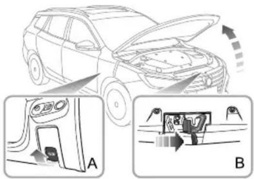
text_image
Diagram illustrating car engine compartment and driver's seat, showing front opening, rear door, and side view with Chinese labels.I Fromtheinsideofthevehicle,pullthebonnetrelease handle(FigureA).
2Movethesafetycatchreleasehandleonthebonnet lockassemblyinthedirectionofthearrow(FigureB) toreleasethebonnetsafetycatch.
3Raisethebonnet, holditup, insertthebonnetsupport rodintothepertureprovided(indicatedwithan arrow). Ensurethebonnetsupportrodissecurely locatedandreleasethebonnet.
ClosingtheBonnet
Supportthebonnetbyonehand,releasethesupportrod usingtheotherhand,andplaceitfirmlyintothesupport rodbase.Thenholdthebonnetusingbothhandsand lowerit,allowingittodropforthelast20cm \~ 30cmto fullyclosethebonnet.
Byattemptingtoliftthefrontedgeofthebonnet,checkif thelockisfullyengagedafterclosingthebonnet.lfitisnot fullyengaged,youmustrepeattheoperation.
BonnetOpenWarning
Ifthebonnetisnotfullyengaged,whentheSTART/STOP switchisintheON/READYposition,thecorresponding alarmiconwillbedisplayedintheinformationmessage
MAINTENANCE
centreoftheinstrumentpack.Ifitisdetectedthatthe bonnetisnotfullyengagedwhilstdriving,anaudible warningwillsound.
IMPORTANT
- Forsafetyreasons,thebonnetshouldbefullylatched whendriving.Thereforeeverytimethebonnetis opened,youmustcheckafterclosingthatthebonnet issecurelylatched,e.g.thebonnetedgeisflushwith thebodyofthecar.
• Y oushouldstopthecarimmediatelywhensafety permitsandclosethebonnetifitisnotclosedfully whendriving. - Bewareofinjurytohandswhilefullyclosingthe bonnetwithadownwardforce.
FrontCompartment

While working in the front compartment, always observethes safety precautions listed under 'Safety in the Garage', refer to 'Maintenance' in 'Maintenance' section.
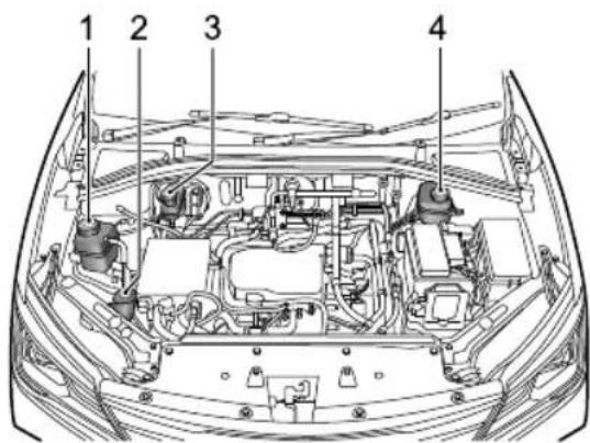
text_image
1 2 3 4I Electric drivetransmissioncoolant expansiontank (blackcap)
2Washerfluidreservoir(bluecap)
3Brakefluidreservoir(blackcap)
4Batterycoolantexpansiontank (blackcap)
MAINTENANCE
CoolingSystem

DONOTremovethecoolantpressurecap whenthecoolingsystemishot-escaping steamorhotcoolantcouldcauseserious injury.
Note: Preventcoolantcomingintocontactwiththe vehiclebodywhentoppingup.Coolantwilldamage paint.
If the coolant level falls appreciably during short period, and you suspect that therem maybe leak, please seek an MGA authorised Repairer for service.
CoolantCheckandT opUp-EDS
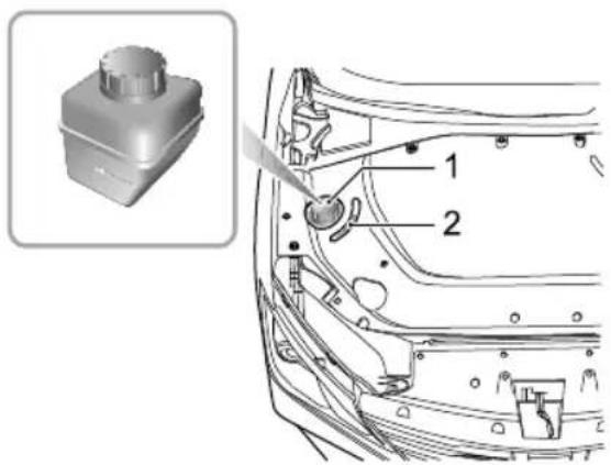
text_image
Technical diagram of a car's front panel with labeled parts, including a component labeled '1' and part '2'.ICoolantExpansionT ankCap
2Viewport
Thecoolingsystemshouldbecheckedweeklywhenthe coolingsystemiscoldandwiththecarrestingonlevel ground.Openthebonnettocheckthecoolantlevelfrom theviewport.Ifthecoolantlevelisbelow"MIN"mark,
MAINTENANCE
openthecoolantexpansiontankcapandtopupcoolant. Thecoolantlevelshouldnotbehigherthan"MAX"mark.
CoolantCheckandT opUp-ESS
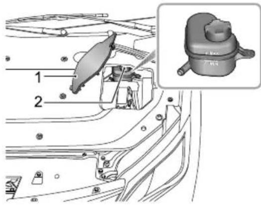
text_image
Technical diagram of a vehicle's internal components with numbered parts and an inset image of the engine cylinder.I BatteryCover
2CoolantExpansionT ankCap
Thecoolingsystemshouldbecheckedweeklywhenthe coolingsystemiscoldandwiththecarrestingonlevel
ground.Openthebonnet,liftthebatterycoverandcheck thecoolantlevel.Ifthecoolantlevelisbelow"MIN"mark, openthecoolantexpansiontankcapandtopupcoolant. Thecoolantlevelshouldnotbehigherthan"MAX"mark.
CoolantSpecification

Coolantispoisonousandcanbefatalif swallowed-keepcoolantcontainerssealed andoutofthereachofchildren.Ifaccidental contactofcoolantbychildrenissuspected, seekmedicalassistanceimmediately.

Prevent the coolant coming into contact with the skinoreyes. If this occurs, in immediately with plenty of water, are still red, painful or uncomfortable, seek medical attention immediately.
Pleaseusethecoolant(mixofwaterandantifreeze)which isrecommendedandcertifiedbyMGUK.Pleasereferto 'RecommendedFluidsandCapacities'in"TechnicalData" chapter.
MAINTENANCE
Note: In an emergency, topup the coolant expansion tank with a small amount of clean water, but be aware of the resultant reduction in frost protection.
Note: The addition of corrosion inhibitors or other additive the coolingsystem of this car may severely disrupt the efficiency of the system and cause electric drivesystem (EDS) and high voltage battery pack (ESS) damage. For cooling system issues please consult an MGA authorised Repairer.
Brake
BrakePads

DONOTrestyourfootonthebrakepedal whiledriving; thismayoverheatthebrakes, reducetheirefficiencyandcauseexcessive wear.
Forthefirst900miles(1500km)youshouldavoid situationswhereheavybrakingisrequired.
Remember that regular servicing is vital to ensure that all the brake components are examined for wear at the correct intervals, and replaced when required to ensure long terms safety and optimum performance during the intervals outlined in the Service Schedule.
Thevehicleneedstoruninfor500miles(800km)after brakepadordiscreplacement.
BrakeFluidCheckandT opUp

Brakefluidishighlytoxic, keepcontainers sealed and out of thereachofchildren. If accidental contact of brakefluidissuspected, seek medical attention immediately.

Preventbrakefluidcomingintocontact withtheskinoreyes.Ifthisoccurs,rinse immediatelywithplentyofwater.Ifeyes arestillred,painfuloruncomfortable,seek medicalattentionimmediately.
Thebrakefluidlevelshouldbecheckedweeklywhenthe systemiscoldandwiththecaronlevelground.
Thebrakefluidlevelcanbeseenthroughthereservoir andshouldbemaintainedbetweenthe"MAX"and"MIN" marks.
Note: Donotallowthebrakefluidleveltodropbelow the "MIN" markorriseabovethe "MAX" mark.
MAINTENANCE
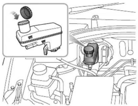
natural_image
Diagram of a car engine intake system with a camera component and a close-up inset showing the engine compartment (no text or labels)Note: Brakefluidwilldamagepaintedsurfaces. If you accidentally spill the brakefluid on the painted surface, soak up any spill agewith an absorbent cloth immediately and wash the area with water or car shampoo.
BrakeFluidSpecification
Usethebrakefluidrecommendedandapprovedby themanufacturer. Referto"RecommendedFluidsand Capacities"inthe"TechnicalData"section.
IMPORTANT
ReplacebrakefluidregularlyaccordingtotheService Schedule.
Battery
BatteryMaintenance

DONOTleaveelectriccomponentsswitched onwhenthevehicleisnotinREADYmode, otherwisethebatterymaybecomeflat, resultinginthefailuretostartthevehicle andthereductionofbatterylife.

Alwaysstorebatteriesupright, tiltingmay allow the corrosivesubstances contained within the battery to leakout.

Neverattempttodismantleabattery, they aresealedunits.
The battery will be visible after the bonnet or the front compartment trim panel is opened. The battery is maintenance-free, therefore there is none to refill fluid.
Note: It is recommended to set the power model to READY for half an hour every week to help extend the service life of the battery. If the vehicle is stored for more than 1 month, removal the negative terminal from
thebattery.Makesurethatthevehiclepowersystem hasbeenturnedoffbeforeconnectingordisconnecting thenegativeterminal.
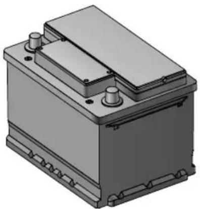
natural_image
3D rendering of a battery housing with mounting feet and internal components (no text or symbols visible)BatteryReplacement

The battery contains sulphuric acid, which is corrosive.
MAINTENANCE
The battery contains sulphuric acid, which is corrosive. Please go to an MG Authorised Repair to remove and refit the battery. Only fit are replacement battery of the sametype and specification as the original to maintain the correct vehicle functionality.

Theusedbatteryshouldnotbediscardedatwill,
foritisharmfultotheenvironment.Itmustberecycledby professionalinstitutes.PleaseconsultanMGAuthorised Repairerformoredetails.
HighVoltageBatteryPack
Precautionsandrestrictedconditionsfor useofbattery

If the vehicle is not going to be used, parked, or stored for all time it is necessary to charge the vehicle at least once every 3 months. During this time, the High Voltage battery state of charges should not be allowed to drop below 50%.

If the battery is initial state of charge and the instrument pack displays'—this indicates that there are less below 10 miles (15km), in this case the vehicle MUST NOT be left in a stored state for more than 7 days without being charged to above 50%.

Failuretofollowtheseguidelineswillresult inHVbatterydamageandinvalidatethe warranty.

DONOTattempttodismantlethebattery packoranyHighVoltagecomponents-THESEAREDANGEROUS.Anysignsof dismantlingordamagecausedbyattempts todismantlewillinvalidatethewarranty.
IDONOTparkthevehicleinconditionswherethe ambienttemperatureexceeds45°Cformorethan15 days. Thiswilleffecttheperformanceandservicelife ofthehighvoltagebattery.
2T omaintainorimprovetheservicelifeofthehigh voltagebattery,itisrecommendedthatyouuseaslow chargingmethodwhereverpossible,rapidcharging shouldonlybeusedforlongdistancejourneysor emergencies.
3Itisrecommendedusingthevehicleatleastoncea month.
Wherepossibleitisrecommendedthatyoucarryout aslowcharging(equalisationcharging)everymonth toextendtheservicelifeofhigh-voltagebattery pack. The batterymanagementsystemwillmonitor thestatusofthehigh-voltagebatterypack;after
MAINTENANCE
monitoringforaperiodoftime,ifanequalisingcharge hasnotbeencarriedoutforsometimethemessage centreintheinstrumentpackwilldisplay'Please ChargeforBMSBalance'.Atthistimeyoumustcarry outanequalisingcharge.Foroperationmode,please referto'EqualisationCharging'in'Starting&Driving' section.
4Intheeventofanaccident,damagetothehigh voltagebatteryoranyofitsrelatedcomponents,or anyrepairsmadetothehighvoltagesystemthecar mustbeinspectedbyqualifiedpersonelatanMG AuthorisedRepairer.
5Intheeventofanyaccidentorbodyrepairsbeing requiredpleaseconsultthequalifiedpersonnelatan MGAuthorisedRepairer .Therepairmayrequirehigh voltagebatteryisolationorspecialistHVcomponent removal.
IMPORT ANT
Onlyfullytrainedandqualifiedpersonelare allowedtoworkonthehighvoltagesystemsand componentsofthisvehicle.Anydisassemblyof suchsystemsorcomponentsisstrictlyprohibited.
Washer
WindscreenWasherFluidCheckandT op Up

Whenfillingthewasherfluid,DONOTlet thewasherfluidspillonthepaintsurface ofvehiclebody.Incasethewasherfluidis spilledonhandsorotherpartsofthebody, pleaseimmediatelywashwithcleanwater.
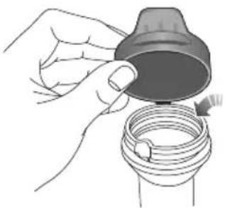
natural_image
Illustration of a hand holding a cap and a coiled tube with a small inset showing a plug (no text or symbols)Checkthewasherfluidleveleveryweek. Whenthelevel ofwasherfluidislow, pleasetopupthewasherfluidas instructed.
Note: DONOTuseananti-freezeorvinegar/water solutioninthewasherreservoir-anti-freezewill damagepaintworkwhilevinegarwilldamagethe washerpump.
IMPORTANT
- Use the washer fluid recommended and certified by the manufacturer. Misuse of washer fluid in winter may caused damage to the washer motordueto freezing.
• Usingthewasherswitchwhenthereisnowasher fluidmaycausedamagetothewashermotor. - Operatingthewiperswhenthewindscreenisdry andthereisnowasherfluidmaycausedamageto thewindscreenandwipers. Pleasespraythewasher fluidandstartthewiperswhenthereisadequate washerfluid.
MAINTENANCE
WasherNozzles
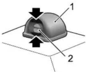
natural_image
3D diagram of a mechanical component with labeled parts (1 and 2), showing directional arrows and no readable text or symbols.Operatethewashersperiodicallytocheckthatthenozzles areclearandproperlydirected.
Thewindscreenwashernozzlesareconfiguredduringthe production,sogenerallythereisnoneedforadjustments.
T oadjustthewindscreenwashernozzle,youcaninserta smallflat-bladedscrewdriverintheupperandbottomgaps (asindicatedbythearrow)between thehousing(1)andthe nozzle(2)andturndownwardorupwardslightlytoadjust toappropriateinjectionangle.
If thenozzleisobstructed, insertaneedleorthinmetal wireintotheholetoremovetheobstruction.
WasherFluidSpecification
Usethewasherfluidrecommendedandcertifiedby themanufacturer .Referto"RecommendedFluidsand Capacities"inthe"TechnicalData"section.
Wipers
WiperBlades
IMPORTANT
- Grease, silicon and petroleum products impair the blade's swiping capability. Cleanthewiper blades in warm soap water, and check their status periodically.
- Cleanthewindscreenfrequently.DONOTusewiperstoremovestubbornoringraineddirt,itwillreducetheir effectandtheirlifespan.
- Ifsignsofhardnessorcrackingintherubberarefound, orifthewipersleavestreaksorunwipedareasonthescreen, thenthewiperbladesshouldbereplaced.
- Cleanthewindscreenregularlywithanapprovedglasscleanerandensurethewindscreenisthoroughlycleaned beforefittingreplacementwiperblades.
- Onlyfitreplacementwiperbladesthatareidenticaltotheoriginalspecification.
- Cleaniceandsnowfromthewipersandensuretheyarenotfrozenorotherwisestickingtothewindscreenbefore attemptingtooperatethem.
MAINTENANCE
ReplacingFrontWindscreenWiperBlades
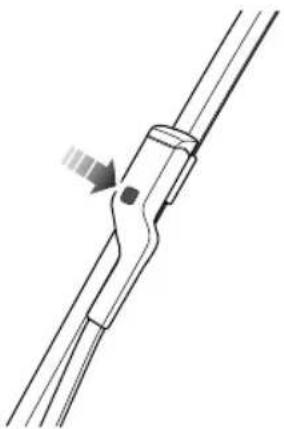
natural_image
Pure mechanical component diagram without any text, numbers, or symbolsIWiththebonnetinclosedstate,andwithin20seconds ofsettingtheSTART/STOPSwitchtotheOFFposition, operatethewiperstalkswitchbypassingdownand releasing,thewiperswillenterthe'serviceposition' andstoponthewindscreen.
2Liftthewiperarmawayfromthewindscreen.
3Pressthebuttononthewiperarm(asillustrated), andpulltheupperendofthewiperbladeoutwardto disengagefromthewiperarm.
4Unhookthebladefromthewiperarmanddiscard.
5Locatethenewwiperintotheslotofthewiperarm.
6Pushthewiperbladetowardsthearmuntilthewiper bladeisengaged.
7 Check whether the wiper blade is fitted correctly to the arm before positioning on the windscreen.
8Operatethewiperstalkswitchbypassingdownagain andreleasing,orsettheSTART/STOPSwitchtoON, thewiperswillexittheservicemodeandautomatically returntoitsoriginalposition
ReplacingRearWiperBlades
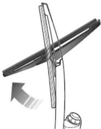
natural_image
Diagram of a wind turbine blade with a rotating arm and base mount (no text or symbols)I Liftthewiperarmawayfromtherearwindow.
2Rotatethewiperbladeasshowninthefigure,to removeitfromthewiperarmanddiscard.
3Positionthefittingofthenewwiperbladeintotheslot ofthewiperarm.Ensurethewipersbladeisproperly securedonthewiperarm.
4Placethewiperassemblybackontherearwindow.
MAINTENANCE
T yre
Overview
• T akeextracarewhenusingnewtyresforthefirst300 miles(500km).
- Avoidexcessivecorneringatspeed.
- Regularlychecktyresforsignsofdamage.DONOT removeforeignobjectssuchasscrewsornailsfromthe tyre.lfatyreshowsanysignsofdamagepleaseensure itisinspectedbyareputabletyrefitterforadvice.
•Preventtyrescomingintocontactwithanychemicals suchasoil,greaseorfuel.
- Ensurevalvecapsarealwaysfitted.
- Ifthetyreistoberemovedalwaysmarkthetyre/wheel orientationtoensurecorrectreinstallation.
- Ifremovedtyresaretobestored, pleaseensurethey arekeptindark,dryandcoolconditions.
NewT yres
Newtyresmaynothavethesameadhesionproperties oftheoldtyres,pleaseruninatmoderatespeedin
appropriatelycarefuldrivingstyleforthefirst300miles (500km). Thisactioncouldbenefittyrelife.
Thedamageofatyreorrimmayhappenunnoticed. If abnormalvibrationorhandlingisexperienced, that means thetyreorrimmayhavebeendamaged. Pleaseslowdown andparkyourvehicleinasuitable, safelocation, thencheck thetyreandrirffyoucan'tseethedamagefromthe outsidecontinuetodrivethevehicleslowlytoareputable tyrefitterorMGAuthorisedRepairerforinspectionand advice.
DirectionalT yres
Directionaltyresaremarkedwith'directionofrotation'(DOR)maintaindliqcharacteristics;re performance,lowroadnoiseandextendtyrelife,tyres mustalwaysbefittedwithindicationarrowshowingthe correct'DOR'.
T yreLife
Correctypressureandoderatdrivingstylean extendtyrelifeRecommendations:
MAINTENANCE
- If the vehicle is restored for lengthy time, please move your vehicle at least once every two weeks to 'rotatethetyres'.
•T yrepressures should be checked monthly when the tyres are cold. - Avoidcorneringatexcessivespeeds.
•Regularlychecktyresforabnormalwearpatterns.
The following factors affect theetyrelife:
TyrePressures
Incorrecttyrepressurescanresultinpoordriving characteristicsandashortenedtyrelifeduetoabnormal wear.
DrivingStyle
Excessivelyharshaccelerationandbraking(tyresemita harshnoise)whilstcorneringwillreducetyrelife.
WheelBalance
Everynewvehicleleavesthefactoryhavinghadthewheels dynamicallybalanced. Outofbalancewheelsmaybedue tomanyfactors.
lfwheelsareoutofbalance, shakingorvibrationofthe steeringmechanismmayoccurandthetyresmaystartto wearexcessively. It is important to restore wheel balance as quick as possible. Each wheel should be balanced after installing anewtyreor having atyrerepair.
WheelAlignment
Incorrectwheelalignmentcancauseexcessivetyrewear and affectvehiclesafety.Ifthetyresshowsignsofabnormal wear,checkthewheelalignmentandseekadvicefroman MGAuthorisedrepairer.
MAINTENANCE
CaringforY ourT yres

DEFECTIVETYRESAREDANGEROUS!
DONOTdriveifanytyreisdamaged, is excessivelyworn, orisinflatedtoanincorrect pressure.
Alwaysdrivewithconsiderationfortheconditionofthe tyres,andregularlyinspectthetreadandsidewallsforany signofdistortion(bulges),cutsorwear.
Note: Avoidtyrecontactwithoils, grease and fuel.
T yrePressures

Beforealongdistancejourney,thetyre pressureshouldbechecked.
Check the pressures at least every month, when the tyres are cold.
Ifitisnecessarytocheckthetyreswhentheyarewarm, youshouldexpectthepressurestohaveincreasedby0.3 \~ 0.4bar(4.35 \~ 5.8psi)thiscircumstanceNEVERair outtheyreordetmatchthecommended pressures(cold).
Valves
Keepthevalvecapsfirmlysecured-theypreventdirtfrom enteringthevalve.Checkthevalveforleaks(listenfora tell-talehissing)whenyoucheckthetyrepressure.
PuncturedT yres
Yourehiclittedwithrewhichmaydeal penetratedbyasharpobject,providedtheobjectremains inthetyre.Ifyouareawareofthisoccurring,reducespeed immediatelyanddrivewithcautionuntilthesparewheel canbefitted,orrepairsundertaken.
Notchesidewallofthetyreisdamagedor distorted, placetyinmediatelpot attemptarepair.
T yreWearIndicators
Theoriginaltyretreadshavea1.6millimeterhighwear markindicatorthatisperpendiculartothewheelrolling directionthe indicator are nouldehtoheread patternteverpointaroundheircumference. markonthesideofatyresuchasuppcaselettering TWloratriangleindicate thepositionofthewearmark.
Whenthetreadhasworndownto1.6mmorbelow,the indicatorswillcometothesurfaceofthetreadpattern, producingtheeffectofacontinuousbandofrubberacross thewidthofthetyre.
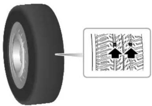
natural_image
Diagram showing a tire with an arrow pointing to a cross-section of a textured surface with two upward-pointing arrows (no text or symbols present)IMPORTANT
AtyreMUSTbereplacedassoonasawearindicator becomesvisible.
ReplacementofT yres

Whenreplacingtyresitisstrongly recommendedthatthenewtyresareof thesamespecificationastheoriginaltyres. Alternativetyres,ofadifferentspecification, orunqualifiedtyresmayadverselyaffectthe car'sdrivingcharacteristicsandsafety.In ordertomaintaincomfortandsafetyitis recommendedtoseekadvicefromanMG AuthorisedRepairer.
Alwayshavereplacementwheelsandtyresbalancedbefore use.
WheelFitmentRotation
It is not recommended that you swap wheels from side to side or front to rear in order to equalisetyewear. Y our vehicle is fitted with T yrePressureMonitoringSystem which means that each wheel is programmed to the relative position.
MAINTENANCE
If youdowishtoswapwheelsandtyresaroundonthe vehiclepleaseconsultanMGAuthorisedRepairerasextra codingwillberequired.
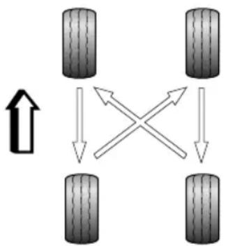
flowchart
graph TD
    A["Terr 1"] --> B["Terr 2"]
    B --> C["Terr 3"]
    C --> D["Terr 4"]
    D --> A
    style A fill:#f9f,stroke:#333
    style B fill:#f9f,stroke:#333
    style C fill:#f9f,stroke:#333
    style D fill:#f9f,stroke:#333
    note1["↑"] above A
    note2["×"] above B
    note3["↓"] above C
    note4["↓"] above D
T yre/SnowChains
Unsuitabletyre/snowchainsmaydamagethetyres, wheels, suspension, brakesorbodyworkofyourcar.
Please pay attention to the following requirements in the usage:
- Thetyre/snowchainscanonlybefittedonthefront wheels;
- Thethicknessoftyre/snowchainsmustnotexceed 12mm;
- Pleasealwaysobservetheinstallationandtension instructionsforthetyre/snowchains,aswellasthe speedlimitationsofdifferentroads;
• Donotdrivefasterthan30mph(50km/h);
•T oavoidthetyredamageandexcessivewearof thetyre/snowchains,thetyre/snowchainsmustbe removedwhiledrivingontheroadwithoutsnow.
Forthisvehicle, theonlyspecification of wheelsandtyresthatwillsupporttyre/snow chainsareasfollows:
Wheelrimsize:6.5J×16
MAINTENANCE
T yresize:205/60R16
Note: If you drive on snow covered and icy roads, it is recommended to use wintertyres. Consultant MG Authorised Repairerford details.
MAINTENANCE
CleaningandVehicleCare

Observeallsafetyprecautionsoncleaning products;donotdrinkfluidsandkeepthem awayfromtheeyes.
Exterior
WashingY ourCar

Somehighpressurecleaningsfystemswill penetratedoor, windowandsunroofseals, anddamagelockmechanisms. DONOTaim waterjetsdirectlyatcomponentsthatmight beeasilydamaged.Ensurethevehiclepower systemisOFFwhenwashingyourcar.

Donotcleanthefrontcompartmentwith highpressurewatersinceitmaydamagethe electricalsystemofthevehicle.
Inordertopreservethepaintfinishonyourcar, please observethefollowingcarepoints:
•DONOTusehotwatertowashthecar.
•DONOTusedetergentsorwashingupliquid.
• Inhotweather, DONOTwasthecarindirectsunlight.
- Whenusingahose, DONOTaimthewaterdirectly atwindow, doororsunroofseals, orthroughwheel aperturesontothebrakecomponents.
Ifthecarisparticularlydirty,useahosetoflushgrimeand gritfromthebodywork,priortowashing.Then,washthe carusingcoldorlukewarmwatercontainingagoodquality washandwaxshampoo.Alwaysuseplentyofwaterto ensurethatgritisflushedfromthesurfaceandnotground intothepaintwork.Afterwashing,rinsethebodywork withcleanwateranddryoffwithachamoisleather.
Cleaningtheunderside
Note: DONOTuseahighpressurehosetocleanthe frontcompartment-damagetothecar'selectronic systemsmayoccur.
Fromtimetotime, but particularly during winter months when salthas been used on theroads, use ahosetowash the underside of the car . Flush away accumulation of mud and thoroughly clean those areas wherede briscaneasily collect (wheel arches and panelseams, forexample).
IMPORTANT
- Avoidcleaningthevehicleindirectsunlight.
- Whencleaningthevehicleinwinteravoidspraying waterdirectlyontodoorlocksandpanelgapsdue toriskoficing.
- Donotuseroughspongesorclothocleanthecar, thiswilldamagethepaintworkfinish.
- Whencleaningtheheadlampsdonotuseadrycloth or sponge, useonlywarmsoapywater.
CleaningwithaHighPressureCleaner
Note: Alwaysreadthemanufacturersoperating instructions.
When using high pressure washers, always ensure there is adequate distance between the spray nozzle and any soft materials, decals or rubber seals.
Note: DONOTdirectthepressurewashernozzledirectlytowardthehighvoltagechargingpointorhighvoltagebatteryconnectionsontheundersideofthevehicle.
IMPORTANT
- Please pay attention to the operating instructions of high pressure cleaner.
• Highpressurecleaners should not be closely directed at soft part of the vehicle.
Removingtarspots
Usewhitespirittoremovetarspotsandstubborngrease stainsfromthepaintwork. Thenwashtheareimmediately withsoapywatertoremovealltracesofthespirit.
BodyProtection
Afterwashing,examinethepaintworkfordamage.Ifthe damagehasrevealedbaremetal,useacoloredprimerfirst, thenapplythecorrectcolourbasecoatandfinishoffwith alacquerpencil,ifappropriateCarryouthistreatment afterwashing,beforepolishingvaxiMore extensivedamagetopaintorbodyworkmustberepaired inaccordancewiththemanufacturer'srecommendations. Failureability validationAnti-Corrosion Warranty.lfindoubt,askyourMGAuthorisedRepairer.
MAINTENANCE
PolishingthePaintwork

DONOTusecarpolishcontainingcoarse abrasives—thesewillremovethepaintfilm anddamagetheglossfinish.
Occasionally treat the paints surface with an approved polish containing the following properties:
- Verymildabrasivestoremovesurfacecontamination withoutremovingordamagingthepaint.
- Fillingcompoundsthatwillfillscratchesandreduce theirvisibility.
- Waxtoprovideaprotectivecoatingbetweenthepaint andtheelements.
Note: If possible, avoid applying polishor wax product stowindow glass and rubber seals.
WiperBlades
Washinwarmsoapywater.DONOTusespiritorsolvent basedcleaners.
WindowsandMirrors
Regularlycleanallwindows,insideandout,usingan approvedglasscleaner.
Windscreen: In particular, clean the outside of the screen with glass clean after washing the car with wash and wax products, and before fitting new wiper blades.
Rearscreen: Cleantheinsidewithasoftcloth, usingaside tosidemotiontoavoiddamagingtheheatingelements.
Note: DONOTscrapeoruseabrasivecleanersonthe insideoftherearscreen—thiswilldamagetheheating elements.
Mirrors: Washwithsoapywater. Useaplasticscraperto removeice. DONOTuseabrasivecleaning compounds ormetalscraper.
PlasticComponents
Aplastomponenstoubleaneding conventionalcleaningmethodsandnotbetreatedwith abrasivematerials.
PaintDamage
Anypaintdamageorstonechipsshouldbetreatedwith suitablepaint/lacquermaterialsimmediatelytoavoid invalidatingtheAntiCorrosionWarranty.
WeatherStripsandRubberSeals
Anyweatherstripsorrubberaperturesealshouldbe treatedwithsuitablematerials(silicagel)iftheyarecleaned usingstrongdetergents,thisshouldavoidanystickingand maintaintheservicelifeoftheseal.
Wheels

Whencleaningthewheelsanymaterialsor waterthatcontactthebrakediscdirectly mayeffectbrakingefficiency.
Inordertoensurethewheelsarekeptinoptimum conditiontheyshouldbecleanedregularly.
Only use are recommended non-acidic propriety wheel cleaner. Always read the instructions on the product.
CleaningtheInterior
Plasticmaterials
Cleanplastic-faced materials with diluted upholstery cleaner, then wipewith adamp cloth.
Note: DONOTpolishdashboardcomponents—these shouldremainnon-reflective.
Carpetandfabrics
Cleanwithdilutedupholsterycleaner-testaconcealed areafirst.
Leather
Cleanleathertrimwithwarmwaterandanon-detergent soap.Dryandpolishtheleatherwithadry,clean,lint-free cloth.
Note: DONOTusepetrol, detergents, furniture creams or polishes as cleaning agents.
MAINTENANCE
InstrumentPack, AudioandNavigationDisplay
Cleanwithadryclothonly.DONOTusecleaningfluids orsprays.
Extendthebelts, thenusewarmwaterandanon-detergent soaptoclean. Allowthebeltstodrynaturally; DONOT retractthemorusethecaruntiltheyarecompletelydry.
AirbagModuleCovers

DONOTallowtheseareastobefloodedwith liquidandDONOTusepetrol,detergent, furniturecreamorpolishes.
T oprotectdamagetotheairbagSRS, the following areasshouldbecleanedsparinglywithadampclothand upholsterycleanerONL Y:
•Steeringwheelcentrepad.
• Areaofdashboardcontainingthepassengerairbag.
- Areaofroofliningandfrontpillarfinisherswhich enclosethesideheadimpactprotectionmodules.
SeatBelts

DONOTusebleaches, dyesorcleaning solventsonseatbelts.
TechnicalData
254TechnicalDataDimensions
256Weights
257 MajorParametersofHighVoltage BatteryPack
258ParametersofT ractionMotor
259RecommendedFluidsand Capacities
260 WheelAlignment(Unladen)
260WheelsandTyres
260TyrePressure(Cold)
T echnicalDataDimensions
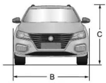
natural_image
Front view of a car with labeled dimensions B (base) and C (height), no text or symbols present.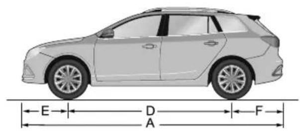
text_image
E D A F| Item,UnitsParameter | |
| OveralllengthA,mm4544 | |
| OverallwidthB,mm1818 | |
| OverallheightC(unladen),mm | 1513(bodyheight)1536(withroofbars) |
| WheelbaseD , mm | 2665 |
| FrontoverhangE,mm | 934 |
TECHNICALDATA
| Item,UnitsParameter | |
| RearoverhangF ,mm | 945 |
| Frontwheeltrack,mm | 1558 |
| Rearwheeltrack,mm | 1553 |
| Minimumgroundclearance(laden),mm|16.1 | |
| Minimumturningcirclediameter,m | 11.3 |
Note: Vehicle length not including the license plate.
Note: Rearviewmirrorsandtheformedportionoftyrewalldirectlyabovethetouchdownpointarenotincluded inthetotalwidth.
TECHNICALDATA
Weights
| Item,Units | Parameters | |
| ExclusiveExcite | ||
| Personincab,person5 | ||
| Unladenvehicleweight(kerb),kg|550|532 | ||
| Grossvehicleweight,kg|992|974 | ||
| Unladenfrontaxleweight,kg887877 | ||
| Unladenrearaxleweight,kg | 663655 | |
| Grossfrontaxleweight,kg99|981 | ||
| Grossrearaxleweight,kg|001993 | ||
MajorParametersofHighVoltage BatteryPack
| ItemParameterValues | |
| T ypeT ernarylithiumionbattery | |
| Ratedenergy,kWh | 52.5 |
| Ratedvoltage,V | 350 |
| Weight,kg | 361 |
| WaterproofGradelP67 |
TECHNICALDATA
ParametersofT ractionMotor
| ItemParameterValues | |
| T ractionmotortypeThree-phasepermanentmagnetsynchronousmotor | |
| ContinuousPower/PeakPower,kW73/120 | |
| RatedT orque/PeakT orque,Nm87.1/260 | |
| RatedSpeed/MaximumSpeed,Rotation/Score8000/15000 | |
| WindingType | winding |
| WaterproofGradeIP67 | |
RecommendedFluidsandCapacities
| Name | GradeCapacity | |
| High-voltagebatterypackcoolant,L | Glycol(OAT)4.4 | |
| Electricdrivetransmissioncoolant,L | Glycol(OAT)4.2 | |
| Electricdrivetransmissionoil,L | ShellSL28080.9 | |
| Brakefluid,LDOT40.8 | ||
| Screenwasherdetergent,L | ZY -VIII | 2.5 |
| Airconditioningrefrigerant,gR1234yf | 600 ± 20 |
TECHNICALDATA
WheelAlignment(Unladen)
| ItemParameter | ||
| Front | Camber | -0^7' ± 45' |
| Castor | 5^12' ± 45' | |
| T oein(T otal) | 0^12' ± 15' | |
| KingpinInclination | 13^06' ± 45' | |
| Rear | Camber | -1^13' ± 45' |
| T oein(T otal) | 0^6' ± 20' | |
T yrePressure(Cold)
| WheelUnladen | |
| FrontWheels | 220kPa/2.2bar/32psi |
| RearWheels | 220kPa/2.2bar/32psi |
WheelsandT yres
| Wheelsize | 6.5J×16 |
| T yresize | 205/60R1696V |
INDEX
A
ABS (Anti-Lock Braking System) 22, 29, 164, 165
ABS Warning 22, 29
Accessory Power Socket 56
Accident Precautions 12
Adaptive Cruise Control 178-187
Air Conditioning 15, 64-77, 134-135, 207, 223, 259
Air Distribution 68-76
Air Recirculation 67, 68, 70-73, 76, 77
Air Vents 64-66, 70, 75
Airbag SRS 80, 86, 93, 97-107, 113, 202, 203, 252
Airbag SRS Service Information 102-104
Airbag SRS Warning 24, 27, 98
Airbags Driver and Front Passenger 100
Airbags – Side Head Curtain 102
Airbags – Side Pelvis/Thorax 101, 102
Alarm System 122-125
Alternative Starting Position 130-131
Anti Theft 121-125, 130
Auto Hold 22, 167-169
Auto Lamps 35
B
Backrest Adjustment – Seats 80, 82-85, 181
Battery - Key 31, 117, 118
Battery (12V) Maintenance 233-234
Battery (12V) Replacement 233-234
Blower 67-77, 135, 203
Bonnet15, 41, 122, 124, 125, 142, 183, 210-213,
225-226, 228, 229, 233, 240
Booster Cables 187-189
Britax Child Seats 112
Brake Fluid 22, 30, 222, 223, 227, 231-232, 259
Brake Fluid Specification 259
Brakes 135, 223, 231, 246
Braking in an Emergency 58, 60, 80, 134, 163, 169, 171, 181
Bulb Replacement 209-219
Bulb Specification 209
C
Capacities 259
Car Wash Precautions 48, 167, 200, 248
INDEX
Centre Vents 64-65, 70, 75
Charging 9, 11, 25, 29, 32, 56-57, 137-150, 206-208
235-236
Charging Ports 9, 57, 140-145, 202
Charging Times 143, 148-150
Child Proof Locks 120
Child Restraints and Seats 51, 92, 97, 105-113
Cleaning – Car Interior 251-252
Cleaning – Paint Work 248-250
Clock 17
Coolant Check and Refill 228-229
Coolant Level 223, 228-229
Coolant Specification 229, 259
Cooperative Regenerative Braking System 162-163
Cruise Control 15, 21, 28, 135, 175-177
Cup Holder 61
Current Journey (Trip Computer) 19
D
Daily Checks 223
Data - Technical 254-260
Daytime Running Lamps 36
Dimensions 254
Dipped Headlamps 35-38
Direction Indicators 27, 38, 39, 184, 209, 212, 227
Direction Indicator Bulb 209, 212, 227
Driving on Hills 155
Driving Mode 15, 17-18, 135, 155-156, 162
Driving Range 8, 68, 74, 147, 162
Door Mirror 47-48, 128, 204, 207
Door Mirror Heater 47, 207
E
EBA (Electronic Brake Assistance) 163
EBD (Electronic Brake Force Distribution) 22, 30, 163
E Call 26, 34, 185-186
Economical Driving 133-134
Electric Drive Number 4-5
Electric Drive Transmission 4-5, 11, 151-152, 159-160, 227, 259,
Electric Motor4, 5, 19-20, 25, 32, 159-160, 258
Electric Motor Number 4-5
Electric Vehicle 7, 138, 140, 206
Electronic Hydraulic Brake Application System 161
INDEX
Electronic Parking Brake 22, 31, 32, 152, 155, 165, 167-169, 208
Electronic Steering Column Lock (ESCL) 23, 30
Emergency 3, 12, 26, 34, 80, 86, 87, 91, 94, 106, 131, 133-134, 142, 163, 164, 169-171, 183-219, 230
Emergency Braking Hazard Control System (HAZ) 169
Emergency Starting 187-189
Energy Flow 20
Energy Regeneration (KERS) 9, 15, 17, 18, 20, 135, 157-158
Environmental Driving 133-134
EPS (Electric Power Steering) 23, 30, 45-46
Equalisation 9, 143, 148-149, 235-236
ETC (Electronic -Temperature Control) * 67-71
F
Fog Lamps and Switch 27, 36, 39
Follow Me Home Lights 36
Foot Brake 161
Front Wiper Operation 40-41, 207
Front Wiper Blade Replacement 240
Fuses, Replacement 201-208
Fuse Box (Passenger Compartment) 202-204
Fuse Box (Front Compartment) 205-208
G
Gauges and Indicators 16
Gear Shift 15, 17, 43, 151-154, 176, 202
Glovebox 58
H
HAZ (Emergency Braking Hazard Warning Light Control) 169
Hazard Warning Lamp 3, 27, 39, 169, 184, 192
Hazard Warning Triangle 184
Head Restraints 80, 83-84,
Headlamp Bulb 209-210
Headlamp Flash 38
Headlamp Levelling 37, 207
Headlamps 35-39, 49, 204, 207, 209, 249
Heated Mirrors 47, 207
Heated Rear Window 47, 67, 71, 72, 76, 207
INDEX
Heavy Loads 133
High Voltage 7-11, 16-17, 20, 33, 135, 138, 140, 143, 148-151, 157, 192, 198, 204-206, 230, 235-236, 257, 259
High Voltage Battery Pack 7-9, 16, 20, 33, 135, 147, 206-207, 230, 235-236, 257
Hill Hold Function 155, 165-166
Horn 15, 46, 124, 129, 206, 223
Hydraulic Booster Compensation System 161-162
|
Identification Numbers 4-6, 111, 185
Immobilisation 31, 110, 121-124, 213
Information Centre 18-19, 21, 27, 29
Instrument Pack 8, 14-16, 21, 26-27, 38-39, 45, 74, 93, 98, 118, 129-131, 135, 143-150, 156, 161-165, 168, 170-175, 202-203, 226, 235-236, 252
Interior Door Handles 126
Interior Lights 55
Interior Locking Switch 125
ISOFIX Restraints 108-112
J
Jump Leads 170, 187
Jump Starting 187
K
KERS 9, 15, 18, 135, 157-158
Keys 31, 36, 52, 54, 88, 116-119, 122-126, 129-131
L
License Plate Lamps 179, 209, 216
Lighting Switch 35-36, 39, 210
Load Carrying 181-182
Locking 117, 122-124, 141-142, 164
M
Main Beam 27, 38, 217
Maintenance 25, 94, 95, 133, 134, 173, 222-224, 233
Manual Front Seats 81-82
Master Lighting Switch 35
Medical Advice and Awareness 138, 140
Mirrors – Door 47-48, 128, 204, 207
INDEX
Mirrors - Interior 49-50
Mirrors Cleaning 250
Mirrors – Folding 48
Mislock 124-125
N
Next Service 222
Number Plate Lamps 179, 209, 216
O
Odometer 17
"One- Touch" Windows 52-53
Opening the Bonnet 225
Overspeed 20
P
Parking Aid * 178-180
Parking Camera * 179-180
Parking Brake 12, 22, 31-32, 129, 131, 151-152, 155, 165, 167-169, 193, 197, 208
Passenger Compartment Fuses 202-204
Pedestrian Alert System 24, 132, 204
Polishing the Paintwork 102, 249-252
Pollen Filter 65
Power Limitation 33, 135, 159
Power Socket 56-57
Power System 7, 12, 20, 22-29, 32-33, 47, 53, 56, 116,
121-124, 128-131, 137, 143-145, 151, 156, 158,
160-161, 166, 168-172, 177, 186, 188, 192, 195, 233
Power - Operated Windows 52-55, 128, 250
Programmed Wash/Wipe 40-41
Protection Mode 159-160
Punctured Tyres 173, 244
R
Rear Fog Lamps 27, 36, 39
Rear Seats – Folding 83, 108, 181
Rear Window Isolation Switch 52-53
Rear Wiper Replacement 241
Rear Wiper Switch and Operation 42-43
Recirculation 67-68, 70-73, 76-77
Recommended Fluids 259
Recovery 12, 190-191
Remote Key 31, 36, 54, 118-119, 122
INDEX
Remote Key Battery 31, 118
Roof Luggage Rack * 62
Routine Maintenance 173, 222-223
Running In 133
S
Safety in The Garage 223
Seat Belt Pre-Tensioners 93-94
Seat Belts 27-28, 80, 83-84, 86-99, 105-108, 114, 154, 166-168, 171, 190, 223, 252
Seat Belt Warning 28
Seat Cushion Height 81-85
Seat – Electric 82-83
Seat - Manual 81-82
Security 31, 116, 124
Side Lamps 27, 35-36
Stability Control System (SCS) 22, 29, 172, 207-208
Snow Chains 246-247
Speed Locking 126
Speedometer 16, 20
SRS Service and Replacement 102
Starting 130-131, 159, 167, 187
Steering Column Adjustment 44
Start/Stop 15, 18, 21, 128-131
Storage Devices 7, 58
Sunvisor 51
Symbols 2
T
Tailgate Opening 116, 122-123, 126
Target Speed 175-177
Technical Data 254-260
Temperature Control - ATC * 72-77
Temperature Control – ETC * 67-71
Top Tether Restraint 109
Towing Eyes 191
Towing For Recovery Precautions 190-193
Traction Control (TC) 22, 29, 172
Transporter or Trailer Recovery 190-193
Trip Computer 19
Trip Meter 17-18
Tyre Pressures 8, 19, 24, 31, 133, 173-174, 196, 198,
204, 242-245, 260
TPMS - (Tyre Pressure Monitoring System) * 24, 31,
INDEX
173, 204, 245
Tyre Wear Indicators 254
Tyres 133-134, 242-246, 260
U
Unlocking 116, 122-125
USB Socket 56-57
V
Vanity Mirrors 51
Vehicle Control 135, 202, 206
Vehicle Identification Numbers4-6
Vehicle Information Display 17-19
Vehicle Recovery 190-193
Ventilation 64-65, 69-71
VIN Plate 4
W
Warning Lights 27-34
Warning Messages21-26
Warning Triangle 3, 184, 197
Warranty I, 235, 249, 251
Washer Jets, Fluid and Refill 223, 237-238
Washing the Car 48, 178, 248-250
Weekly Checks 223, 228-231
Weights 256
Welcome Lights (Find My Car) 36
Wheels 163-164, 167, 172, 174, 190-193, 197, 199,
243, 245-246, 251, 260
Wheel Alignment 260
Windows 52-55
Window Lift Switch 15, 52-53
Windows – Cleaning 250
Windscreen Washer Check and Top-Up 237-238
Windscreen Wipers 40-43, 223, 237
Wiper Blade – Cleaning 239
Wiper Blade Replacement 240-241
Wiper Controls 40-43