
Bee 50-C - Light Hive - Free user manual and instructions
Find the device manual for free Bee 50-C Hive in PDF.


| Product Type | Smart LED Light |
| Brand | Hive |
| Model | Bee 50-C |
| Dimensions | 12 cm diameter x 15 cm height |
| Weight | 200 g |
| Power Supply | AC 100-240V, 50/60 Hz |
| Power Consumption | 10W (max) |
| Light Source | LED (non-replaceable) |
| Color Temperature | 2700K - 6500K adjustable |
| Brightness | Up to 800 lumens, dimmable |
| Connectivity | Wi-Fi 2.4 GHz, Bluetooth 5.0 |
| Compatibility | Works with Hive app, Alexa, Google Assistant |
| Functions | On/Off, dimming, color tuning, scheduling, scenes |
| Material | Aluminum heat sink, polycarbonate diffuser |
| Installation | Plug and play, no hub required |
| Protection Rating | IP20 (indoor use only) |
| Operating Temperature | 0°C to 40°C |
| Package Contents | 1x Bee 50-C light, 1x user manual |
| Warranty | 2 years |
| Maintenance | Wipe with a soft, dry cloth. Do not use abrasive cleaners. |
| Safety Instructions | Do not expose to water. Disconnect power before cleaning. |
| Spare Parts & Repairability | Contact Hive customer service for any issues. The LED is non-replaceable. |
| General Information | This product is designed for residential use. For commercial use, consult manual. |
Frequently Asked Questions - Bee 50-C Hive
User questions about Bee 50-C Hive
0 question about this device. Answer the ones you know or ask your own.
Ask a new question about this device
Download the instructions for your Light in PDF format for free! Find your manual Bee 50-C - Hive and take your electronic device back in hand. On this page are published all the documents necessary for the use of your device. Bee 50-C by Hive.
USER MANUAL Bee 50-C Hive
natural_image
Black hexagonal logo with a white letter 'H' in the center (no additional text or symbols)C-SERIES USER MANUAL
natural_image
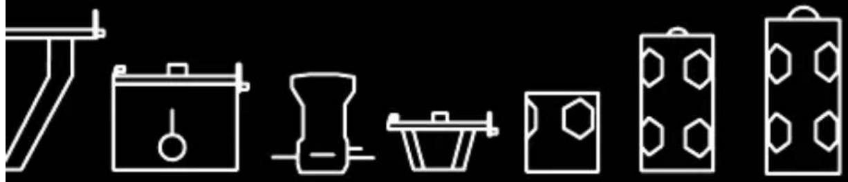
Pure line drawings of six household items (no text or symbols)BEE 50-C
WASP 100-C
HORNET 200-C
OPERATING INSTRUCTIONS
HIVELIGHTING.COM
INFO@HIVELIGHTING.COM
(310) 773 4382
HIVE LIGHTING
525 S HEWITT ST.
LOS ANGELES CA 90013
NOTE: Most up to date version of this manual, along with other support info, can be found at: hivelighting.com/documentation
Welcome,
Thank you for your purchase of a Hive Omni-Color LED. The C-Series luminaires from Hive Lighting are designed for use in permanent, semi-permanent and mobile lighting applications.
Combining energy efficient LEDs with our Perfect S.H.O.T. controls we hope you find the LED to be the perfect instrument for any lighting application. We hope this manual serves as a helpful companion to your new light and answers all the questions you may have, but please do not hesitate to take advantage of our website and tech support services.
Sincerely,
Hive Lighting
TABLE OF CONTENTS
5 SAFETY INFORMATION
6 General Guides
7 FCC Info
7 Maintenance
9 BEE 50-C
11 WASP 100-C
13 HORNET 200-C
15 OPTICAL ACCESSORIES
15 Par Reflector
16 Super Spot Reflector
16 Leko Spot
17 Adjustable Fresnel
18 Profoto Compatibility
19 Lenses
20 Barndoors
21 MOUNTING ACCESSORIES
21 Standard Yoke
22 Studio Yoke
23 Safety Chain
23 Power Mounting
24 Profoto Yoke
27 POWER
28 AC/DC
28 Battery
29 CONTROLS
29 Control Panel
31 Perfect S.H.O.T.
33 Local Controls
35 Effects, Sources, Profiles
39 DMX
41 CMRX (Wireless DMX)
45 DMX/ CMRX Table
47 Firmware Updates
48 Mobile App
49 POLICIES
49 Product Modification Warning
49 Limited Warranty
50 Returning an Item for Repair
52 Refund Policy
53 Freight Policy
SAFETY INFORMATION

WARNING: Risk of Electric Shock! All C-Series lights are a lighting product powered by sufficient electricity to cause harm to the human body. Do not install or operate fixture while standing in water or underwater. Failure to observe this safety information or to ignore common sense may cause serious injury or even death.

CAUTION: High Beam Intensity! Do not look directly into the light source for an extended period. Hive C-Series fixtures emit light in the visible spectrum, and do not emit Ultraviolet or Infrared portions of the electromagnetic spectrum. Incidental heat generation from the standard operation of any electronics may occur.

CAUTION: Devices and accessories must always be properly secured against falling when mounted above floor level. Always observe common and local safety regulations.
GENERAL GUIDES:

Defective components, attached cables or electronic devices connected to it must not be used. If you suspect there is damage to the product's internal components, do not open the housing. Doing so will void all warranties.

Do not operate the light if damaged, or if any cables or devices that the light is connected to have been damaged.

Product complies with DMX512 standards only. Light may not be operated with aid of an AC dimming system.


Do not sit or submerge product in water. (IP65)

ONLY use approved DC Power Sources within acceptable voltage. Check that power source complies before handling. It is strongly recommended that the user powers light with either the provided AC/DC adapter or a Hive-approved Battery Adapter.

Do not position or mount the product near open flames.

Unobstructed airflow is required for effective cooling. Allow minimum of one inch clearance around air vents for proper ventilation.
FCC Information
This equipment has been tested and found to comply with the limits for a Class A digital device, pursuant to Part 15 of the FCC rules. These limits are designed to provide reasonable protection against harmful interference when the equipment is operated in a commercial environment. This equipment generates, uses, and can radiate radio frequency energy and, if not installed and used in accordance with the instruction manual, may cause harmful interference to radio
MAINTENANCE:
communications.
Help prevent damage and prolong the
life of your equipment by following these suggestions:
With the unit unplugged, lightly wipe the outer metal housing with a soft, clean towel and blow with compressed air.
Clean the control panel with cotton swabs wetted with isopropyl alcohol.
Clean the reflector and lenses with a dry chamois or compressed air. Avoid touching any of these components with your fingers directly.

Do not operate product when operating environment is in excess of 40^ C ( 115^ F).
Do not misuse the power connector to hold, move or suspend the fixture.
Disconnect all cables prior to transport.
Store light in a cool, dry place (between 5 - 23°C).
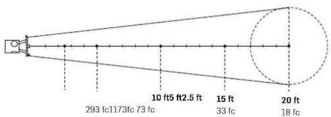
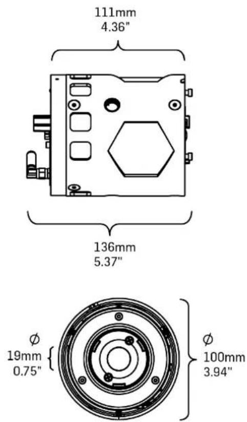
BEE 50-C
SOURCE: Omni-Color LED
LIGHT INDEX: Up to 98 CRI / 97 TLCI
DIMMING: 0 - 100% Control
COLOR TEMP: 1,650K - 8,000K
CONTROL: DMX, Smartphone
AC POWER: 100 - 240 V input
DC POWER: 12 - 18 V input via XLR
LENGTH: 5" / 127mm
DIAMETER 4" / 100mm
WEIGHT: 1.5 lbs. / 0.7 kg.
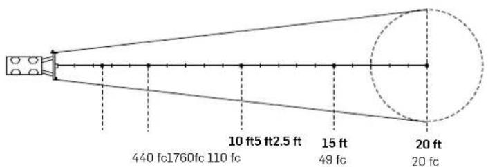
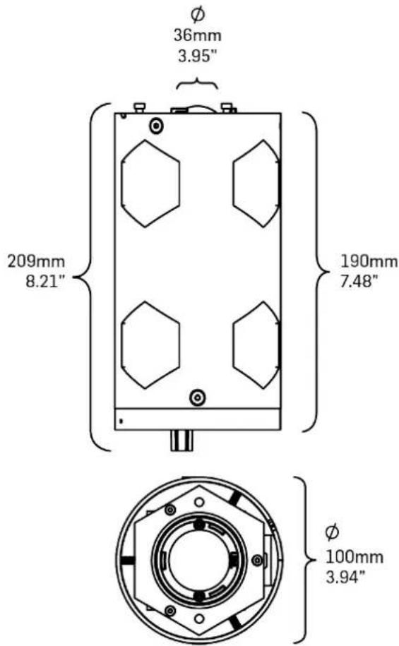
WASP 100-C
SOURCE: Omni-Color LED
LIGHT INDEX: Up to 98 CRI / 97 TLCI
DIMMING: 0 - 100% Control
COLOR TEMP: 1,650K - 8,000K
CONTROL: DMX, Smartphone
AC POWER: 100 - 240 V input
DC POWER: 12 – 20 V input via XLR
LENGTH: 8.25" / 210mm
DIAMETER 4" / 100mm
WEIGHT: 2.3 lbs. / 1.1 kg.
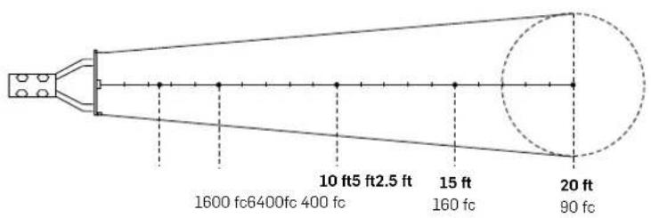
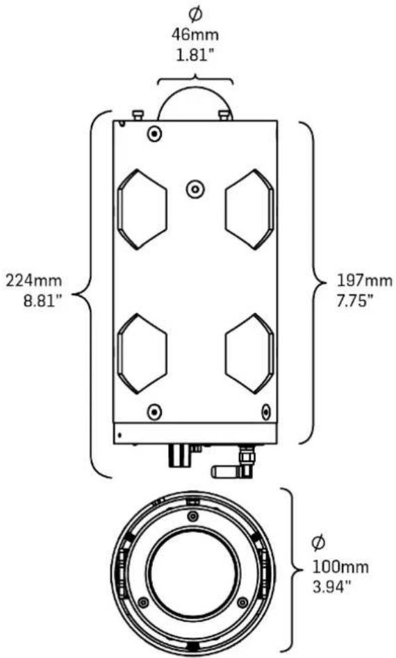
HORNET 200-C
SOURCE: Omni-Color LED
LIGHT INDEX: Up to 98 CRI / 97 TLCI
DIMMING: 0 - 100% Control
COLOR TEMP: 1,650K - 8,000K
CONTROL: DMX, Smartphone
AC POWER: 100 - 240 V input
DC POWER: 24 - 36 V input via XLR
LENGTH: 9" / 229 mm
DIAMETER 4" / 100mm
WEIGHT: 2.6 lbs. / 1.2 kg.
C-SERIES ACCESSORIES
OPTICS

PAR REFLECTOR
The Par Reflector and protective cage can be detached in order to accommodate a different accessory, such as an alternative reflector or softbox. Pull back the locking plunger on the arm of the Par Reflector. With the plunger disengaged press firmly on reflector cage and twist counterclockwise to release the reflector plate from locking pins. Rotate counterclockwise and pull gently to loosen. To reattach, center the reflector's keyed grooves over the housing pins, insert, and rotate clockwise.
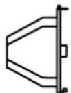
The Super Spot Reflector and protective cage can be detached in order to accommodate a different accessory, such as an alternative reflector or softbox. Pull back the locking plunger on one arm of the Super Spot Reflector. With the plunger disengaged press firmly on the reflector cage and twist counterclockwise to release the reflector plate from locking pins. Rotate counterclockwise and pull gently to loosen. To reattach, center the reflector's keyed grooves over the housing pins, insert, and rotate clockwise.

LEKO SPOT
The Mini ETC© Source 4 Lens and Shutter Barrel Housing and Leko Spot Adapter Plate can be detached in order to accommodate a different accessory, such as an alternative reflector or softbox. To remove, rotate counterclockwise and pull gently to loosen. To reattach, center the adapter plate's keyed grooves over the housing pins, insert, and rotate clockwise.

ADJUSTABLE FRESNEL
The Adjustable Fresnel can be removed from the housing in order to accommodate a different accessory, such as an alternative reflector or softbox. To attach or reattach the Adjustable Fresnel slide the Fresnel Attachment into the "spot" or fully extended position. Once fully extended lock the slide by tightening the knob on the side of the Adjustable Fresnel. Once the slide is locked, pull up on the locking plunger on the back plate of the Adjustable Fresnel. With the plunger disengaged, grip the Adjustable Fresnel firmly and twist counterclockwise to release the backplate from the locking pins. Rotate counterclockwise and pull loosely until free. To reattach, center the Adjustable Fresnel's keyed grooves over the housing pins, insert, and rotate clockwise.
The Adjustable Fresnel is designed to adjust its beam angle over 40 degrees between a tight spot and a broad flood. To adjust the beam the front fresnel lens optic can be slid closer or farther away from face of the light.
To adjust the fresnel lens position loosen the knob on the side rail of the Adjustable Fresnel. Once fully loose, slide the lens into the desired position to create the desired beam of light. Once in position hold the fresnel in place and tighten the side knob, fully securing the lens and locking the slide.

PROFOTO © COMPATABILITY
All C-Series lights have a 100mm diameter. This diameter allows for the light to easily be paired with all accessories designed for the strobe lights produced by Profoto©. This allows for the use of a wide variety of light modifiers from third party manufacturers originally designed for both still and motion photography. Hive Lighting also produces a number of accessories designed for this standard diameter.
To attach a light modifier using a Profoto© style mounting ring be sure to first remove any other light modifier from the front of the fixture. When the light is set up as an "open face" fixture with only the domed diffuser on
the front of the fixture, carefully slide the mounting ring over the body of the light. Each light modifier can be positioned differently to create the optimal desired lighting effect. Once the desired position of the light modifier to the domed diffuser is achieved, secure the ring in place by closing the locking clamp attached to the rubber collar on the outside of the mounting ring.
ADDITIONAL OPTICS:
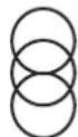
Lenses
Separately purchased lens kits include 3 interchangeable HDP Lenses: Medium, Wide and Super Wide. To affix these to the device, follow these steps: Rotate the top clip until it is parallel to the reflector face. Slide the desired lens into the reflector cage's inner lens stage, or slot (pictured on Page 16). Rotate the top clip back into its locked position. Rotate lenses with elliptical beams in order to position light projection in desired location.
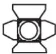
Barndoors
The barndoors can allow for greater control in shaping the light. To attach: Rotate the top clip until it is parallel to the reflector face
Slide the barndoors into the reflector cage's outer lens stage, or slot. Rotate the top clip back into its locked position. Adjust one or more of the leaves (i.e. "doors") of the barndoors to cut or shape the beam of light emitted by a C-Series Light™.
MOUNTING
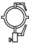
STANDARD YOKE
All C-Series lights may be operated when securely mounted to a separate apparatus, such as a stand (purchased separately). Carefully position the light above stand. Place the top of the stand into the 5/8th (16mm) receiver mount, located on the base of the yoke. Continue to hold the light securely with one hand, and use the other to twist the Yoke's locking knob clockwise until tight.
Tilting (Vertical Adjustment)
Loosen the tilt lock on the yoke until the light can move freely. Adjust the light upward or downward at any angle between 0^ and 180^ (vertical). Secure the tilt lock once desired angle is reached.
Panning (Horizontal Adjustment)
Loosen the mount lock on the yoke. Freely adjust the light left to right up to a full 360° horizontal rotation. Secure the mount lock once desired angle is reached.
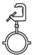
STUDIO YOKE
All C-Series lights may be operated with Hive's studio yoke when securely mounted to a permanent or temporary lighting grid or truss (sold separately). Carefully position the light below the pipe or truss. Place the opening of the pipe clamp located on the base of the yoke so that the top of the hook rests securely on the pipe or rod. Continue to hold the light securely with one hand, and use a wrench, vice grip or similar tool (sold separately) to twist the mount's locking screw clockwise until tight.
Tilting (Vertical Adjustment)
Loosen the tilt lock on the yoke until light can move freely. Adjust the light upward or downward at any angle between 0^ and 180^ (vertical). Secure the tilt lock once the desired angle is reached.
Panning (Horizontal Adjustment)
Loosen the mount lock screw on the pipe clamp. Freely adjust the light left to right up to a full 360° horizontal rotation. Secure the mount lock once the desired angle is reached.
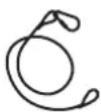
SAFETY CHAIN ATTACHMENT
A standard safety chain may be attached to any C-series Light either through a key ring on the Standard Yoke tab, or through an eye bolt with 1/4"-20 on the light's interface
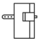
POWER ACCESSORY MOUNT
Both the Standard Yoke and Studio Yoke have mounting tabs 180 degrees apart, at 90° and 270°, on the outer diameter of the yoke. These tabs allow for a variety of power accessories to be mounted directly to the C-Series fixture. The primary accessories that can be mounted here are the Power Supply Mounting Bracket and the Battery Plate mount.
To mount power accessories to the yoke, use the receiver tab on the back of each accessory, which mates with the mounting tab on the yoke. The receiver tab has a pull pin lock, pull up on the pin lock until the pin fully clears the receiver tab. When the receiver tab is clear, center the mounting tab on the yoke inside
NOTE: Please visit www.hivelighting.com to learn more information about all of the C-Series' different power accessories and mounting options.
the receiver tab on the accessory so that the pull pin can drop down into the through hole on the receiver tab. It is properly mounted and immovable when the pin has fully descended into the hole.
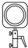
PHOTO YOKE
All C-Series lights may be operated with the Photo Yoke when securely mounted to a separate apparatus, such as a stand (purchased separately). Carefully position the light above stand. Place the top of the stand into the 5/8th (16mm) receiver mount, located on the base of the yoke. Hold the light securely with one hand, and use the other to twist the mount's locking knob clockwise until tight.
The C-Series fixture is secured inside of the Photo Yoke using a Profoto© style mounting ring around the outer diameter of the C-Series fixture. Once the desired position of the C-Series fixture is achieved, secure the ring in place by closing the locking clamp attached to the rubber collar on the outside of the mounting ring.
Attaching Light Modifiers
The Photo Yoke is designed with two unique mounting points unlike the Standard Yoke or Studio Yoke. The Photo Yoke itself also serves as a Four-Point Speed Ring, allowing Square and Rectangular Softboxes to be connected directly to the yoke itself without the need for additional mounting accessories.
The Photo Yoke also has a mounting point in the base of the yoke for photographic umbrella attachments. To attach a standard photo umbrella insert the metal pole of the umbrella into the mounting point on the top half of the photo yoke base, just above the tilt lock. Once the umbrella is inserted securely position the umbrella the desired distance from the face of the C-Series fixture. Then secure the umbrella position by tightening the threaded knob above the tilt lock until the bolt of the threaded knob is holding the umbrella pole inside the mounting point securely. The umbrella will now pan and tilt with the fixture.
Tilting (Vertical Adjustment)
Loosen the tilt lock on the yoke until the light can move freely. Adjust the light upward or downward at any angle between 0^ and 180^ (vertical). Secure the tilt lock once the desired angle is reached.
Panning (Horizontal Adjustment)
Loosen the mount lock on the yoke. Freely adjust the light left to right up to a full 360° horizontal rotation. Secure the mount lock once the desired angle is reached.
POWER
ONLY use Hive Lighting provided power supplies with the C-Series lights. Each C-Series fixture has a specific power supply and CANNOT be used on other models. There are two options for powering the light:
BEE 50-C:
AC/DC: 12VDC Power Source within acceptable voltage range of 12-18V DC.
Battery: 12V, 14.4V, 14.8V (60Wh or higher)
WASP 100-C:
AC/DC: 19VDC Power Source within acceptable voltage range of 12-20V DC.
Battery: 14.4V (90Wh or higher)
HORNET 200-C:
AC/DC: 36VDC Power Source within acceptable voltage range of 24-36V DC.
Battery: 14.4V run in series*, 26V, 28V (160Wh or higher)
* NOTE: Only use Hive Lighting's Y-Cable adapter for running 14.4V batteries in series to the Hornet 200-C. Only use two of the same battery packs and ensure that both packs are fully charged before using.
AC/DC ADAPTER (INCLUDED)
- Connect the provided AC/DC adapter to the light via the 4-pin XLR cable (XLR pin wiring pin 1 - DCV In and pin 4 + DCV In), which is inserted into the corresponding power socket on the light's control panel.
- Connect the adapter's power cable into the wall or to a generator.
- Turn the fixture on by flipping the power switch to the "on" position (up), located on the control panel, causing the power indicator light to illuminate.
BATTERY (SOLD SEPARATELY)\*
- Attach the battery's D-Tap to 4-Pin XLR adapter cable to the battery, with the other end connecting to the light via the power socket in the control panel.
- Turn the light on by flipping the power switch to the "on" position (up), located on the control panel. This will cause the power indicator light to illuminate.
CONTROLS
CONTROL PANEL
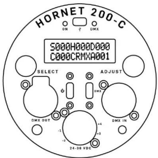
- On/Off Switch - Controls Power. The power indicator light above the display illuminates when power is on.
- DMX Mode On/Off Switch - Controls DMX mode when unit is attached to a DMX board (See Page 20 for more instructions). The DMX indicator light, above the display, illuminates when the fixture is in DMX mode.
- Left "Selector" Knob - Selects the S.H.O.T. ^™ property.
- Right "Adjustment" Knob - Selects the S.H.O.T. ^TM property's desired value. When in DMX mode, this knob is used to adjust the light's starting DMX address.
-
DMX IN Socket - Connect fixture to your DMX board via a 5-pin XLR cable.
-
DMX OUT Socket - Connect fixture to another light via a 5-pin XLR cable when using one DMX board to control multiple units. All C-Series lights follow DMX512 standards, allowing multiple lights to be "daisy chained" together. The device is self-terminating to maintain data integrity.
- Power Socket - Connect the fixture to valid power source via the 4-Pin XLR power cable that comes included with adapter (For XLR Pin wiring Pin 1- DCV In and Pin 4+ DCV In).
- Display - Provides digital readout for values of all controllable light properties.
- USB Port - Used to connect light to computer when firmware updates are made available by Hive.
PERFECT S.H.O.T. SYSTEM
The light emitted by all C-Series LEDs can be configured via Hive's Perfect S.H.O.T. ^™ system, which controls these four properties:
Saturation
(denoted by "S" on the display)
Hue
(denoted by "H" on the display)
Output or Dimming
(denoted by "D" on the display)
Color Temperature
(denoted by "K" for degrees in Kelvin when in local mode, or by "C" when in DMX mode.)
There are three ways to use the Perfect S.H.O.T. ^™ system:

LOCAL CONTROL
Using the light's own digital control panel. Local control is useful for those who don't have access to a DMX board, or who are working on simpler projects.
DMX/CRMX
Via a DMX/CRMX board (purchased separately). When in this mode, the Perfect S.H.O.T. ^™ system is controlled via this external device, with a fifth property - the board's starting address - controlled on the light itself.
SMARTPHONE
Via the Hive iOS App, which allows your iphone or ipad to control the app via a bluetooth connection.
LOCAL CONTROL
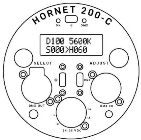
- Engage Local Mode: Flip the DMX On/Off Switch to the down position, causing the DMX light to turn off. You are now in LOCAL MODE, and the digital display will look like this:
- IMPORTANT: In local mode, color temperature is indicated by the letter "K" because the color temperature range of 1650 - 8000 is in Kelvin.
- Select Property With Left Dial: Turn the left dial in either direction to toggle through the four properties.
- Select Property Value with Right Dial: There are two ways to select the property value with the right dial.
- Fine Adjustment: Click the ADJUST dial in once if in coarse control, then turn in either direction to change the active property's value by increments of 1. (The only exception is Color Temperature, which adjusts in increments of 25K).
- Coarse Adjustment: Click once if in fine control then turn the ADJUST dial in either direction. The active property's value will now change in increments of 10 (with Color Tem-
perature incrementing by 200K).
- Dial Lock: The local control dials can be locked to prevent accidental changes in the settings of the light. To lock the dials push and hold the ADJUST knob for four seconds until a small lock icon appears on the bottom right hand corner of the OLED screen. To unlock the dials again push and hold the ADJUST knob for four seconds until the lock icon disappears.
ACCESSING EFFECTS, SOURCES, AND PROFILES
C-Series lights have three additional menus for unique controls not available through the standard S.H.O.T. control menu. These three menus can be accessed by double clicking the selection knob on the on the back of the C-Series fixture. This will bring up the Additional Menus Screen and offer you 3 Menu choices: EFFECTS, SOURCES, PROFILES.
EFFECTS MENU
To access the Effects menu first double click the SELECT knob to access the additional menus screen. There single click the SELECT knob when the screen reads "MENU 1/3 Effects".
To select different effects turn the SELECT knob to scroll between 8 different effects: Police Car, Club Lights, Paparazzi, Color Chase, Fire, Fireworks, Pulsing, TV.
* NOTE: Additional Menus and the settings within are subject to change with new firmware updates! Check www.hivelighting.com for current firmware and Menu options.
The effects can be adjusted either with dimming control or speed control or both dimming and speed control. To adjust the dimming or speed control on any effect turn the ADJUST knob to reach the desired level as indicated on a scale of 1-100%. To toggle between adjusting speed and dimming on an effect with both controls click the SELECT knob once.
To exit the Effects menu to the Additional Menus Screen single click the ADJUST knob.
SOURCES MENU
To access the Sources menu first double click the SELECT knob to access the additional menus screen. There single click the SELECT knob when the screen reads "MENU 2/3 Sources".
To select different sources turn the SELECT knob to scroll between 40 preset sources:
Violet Glo Stick, Pink Glo Stick, Yellow Glo Stick, Red Glo Stick, Green Glo Stick, Blue Glo
Stick, Red Traffic Light, Yellow Traffic Light, Green Traffic Light, Amber Caution, Road Flare, Blow Torch, Bioluminescence, Computer Monitor, Mobile Phone, Sun Blue Hour, Sun Overcast, Sun Direct, Gaslight, Candlelight, Antique Bulb, Warm Antique Bulb, Christmas Lights, Night Light, Heat Lamp, Grow Light, Tungsten, Incandescent, Halogen, HMI, High Pressure Sodium, Low Pressure Sodium, Mercury Vapor, Metal Halide, Ceramic, Carbon Arc, Xenon, Blacklight, Cool White Fluorescent, Warm White Fluorescent
The sources can be adjusted with dimming control. To adjust the dimming turn the ADJUST knob to reach the desired level as indicated on a scale of 1-100%.
To exit the Effects menu to the Additional Menus Screen single click the ADJUST knob.
PROFILES MENU
To access the Profiles menu first double click the SELECT knob to access the additional menus screen. There single click the SELECT knob when the screen reads "MENU 3/3 Profiles".
To select different Profiles turn the SELECT knob to scroll between 3 different profiles: Photo, Cinema, Broadcast
To exit the Effects menu to the Additional Menus Screen single click the ADJUST knob.
Once the profile is selected and the Additional Menu Screen is exited the OLED display will indicate the selected profile with a letter in the upper right hand corner of the display. "P" for Photo, "C" for Cinema, "B" for Broadcast.
DMX MODE
- Connect DMX Board: Connect your DMX512-compliant device to the fixture via the DMX "In" Socket on the right side of the Control Panel
NOTE: Any values for S, H, D & C that have been provided by the DMX board will persist even after the DMX board has been unplugged. Conversely, if the controls on the DMX board are adjusted post-separation and then the board is reconnected, the light will overwrite the previous ones.
-
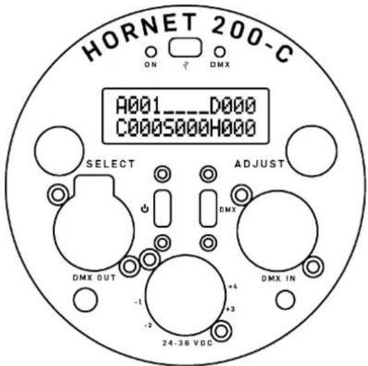
Engage DMX Mode: Flip the DMX Mode On/Off Switch to the up position, the DMX indicator light will turn on. You are now in DMX mode and can use a DMX board to control the light. Your digital display will look like the facing graphic and will register value changes via the connected DMX board.
-
Adjust Starting Address: You will also notice that there is a fifth symbol when in DMX mode - "A". This indicates the light's starting address, and its value determines which controls on the DMX board are used to operate the light. The starting address can be any value between 1 and 512. Selecting the one you want can be achieved in two different ways via the control panel's Right Dial:
a. Coarse Adjustment: Turn the right dial in either direction to change the address' value in increments of 10.
b. Fine Adjustment: Press the right dial in slightly, then continue to press in while turning in either direction to change the value by increments of 1.
CRMX (WIRELESS DMX) BY LUMENRADIO
-
Engage DMX Mode: Flip the DMX Mode On/Off Switch to the up position, causing the DMX indicator light to turn on. This light tells you that you are now in DMX mode and can use a DMX board or CRMX transmitter to control the light.
-
To Select Lumen Radio from the DMX input menu:
a. Double click the selection knob to enter the DMX menu.
b. Once the DMX menu is open single click the selection knob to select DMX input.
c. Rotate the selection knob to select between CRMX and Local Wire. Select CRMX for wireless control, then single click the selection knob to exit to the main DMX menu double click to exit the menu.
- When you have successfully selected Lumen-Radio the DMX menu will now read CRMX on the OLED display on the back of the C-Series fixture.
- Link your LumenRadio transmitter. To successfully use wireless DMX with the C-Series lights, you must have a LumenRadio (CRMX) enabled transmitter connected to your DMX controller. To link your transmitter:
a. Ensure the antenna is connected.
b. Power on the transmitter and receiver(s).
c. Ensure that the RF Link indicators on all receivers are off to indicate
that the receiver(s) are ready to be linked (If necessary, follow the unlink procedure).
d. On the transmitter, press and release the link button.
e. The transmitter will search for any unlinked receivers. Its RF Link indicator will flash for 10 seconds and normal operation will resume.
f. The RF Link indicator will change to a steady on-state on successfully linked receivers.
- To Unlink from a LumenRadio transmitter select:
a. Double click the selection knob to enter the DMX menu.
b. Once the DMX menu is open single click the selection knob to select linking.
c. Click the selection knob to unlink, then confirm unlink.
DMX CONTROLS
DMX CONTROL
Menu Symbol A
Value Control 1-512
Fast Control Right Knob default
Fine Control Right Knob, push & hold
Fast Control Increments 10
Fine Control Increments 1
DMX CHANNELS
CHANNEL PROPERTY DMX 0 DMX 255
Channel 1 Dimming Off Full Brightness
Channel 2 CCT 1650 K 8000K
Channel 3 Saturation 0% (White) 100% Full Color
Channel 4 Hue 0° Hue 360° Hue
| 130 | 4900 K | 130 | 51 % | 130 | 51 % | 130 | 184 ° |
| 140 | 5150 K | 140 | 55 % | 140 | 55 % | 140 | 198 ° |
| 150 | 5400 K | 150 | 59 % | 150 | 59 % | 150 | 212 ° |
| 155 | 5525 K | 155 | 61 % | 155 | 61 % | 155 | 219 ° |
| 160 | 5650 K | 160 | 63 % | 160 | 63 % | 160 | 226 ° |
| 165 | 5755 K | 165 | 65 % | 165 | 65 % | 165 | 233 ° |
| 170 | 5900 K | 170 | 67 % | 170 | 67 % | 170 | 240 ° |
| 175 | 6052 K | 175 | 69 % | 175 | 69 % | 175 | 247 ° |
| 180 | 6150 K | 180 | 71 % | 180 | 71 % | 180 | 254 ° |
| 185 | 6275 K | 185 | 73 % | 185 | 73 % | 185 | 261 ° |
| 190 | 6400 K | 190 | 75 % | 190 | 75 % | 190 | 268 ° |
| 195 | 6525 K | 195 | 76 % | 195 | 76 % | 195 | 275 ° |
| 200 | 6650 K | 200 | 78 % | 200 | 78 % | 200 | 282 ° |
| 205 | 6775 K | 205 | 80 % | 205 | 80 % | 205 | 289 ° |
| 210 | 6900 K | 210 | 82 % | 210 | 82 % | 210 | 296 ° |
| 215 | 7025 K | 215 | 84 % | 215 | 84 % | 215 | 304 ° |
| 220 | 7150 K | 220 | 86 % | 220 | 86 % | 220 | 311 ° |
| 225 | 7275 K | 225 | 88 % | 225 | 88 % | 225 | 318 ° |
| 230 | 7400 K | 230 | 90 % | 230 | 90 % | 230 | 325 ° |
| 235 | 7525 K | 235 | 92 % | 235 | 92 % | 235 | 332 ° |
| 240 | 7650 K | 240 | 94 % | 240 | 94 % | 240 | 339 ° |
| 245 | 7775 K | 245 | 96 % | 245 | 96 % | 245 | 346 ° |
| 250 | 7900 K | 250 | 98 % | 250 | 98 % | 250 | 353 ° |
| 255 | 8025 K | 255 | 100 % | 255 | 100 % | 255 | 360 ° |
| DMX | DIMINE | DMX | SATURATION | DMX | HUE |
| 0 | 0% | 0 | 0% | 0 | 0° |
| 5 | 2% | 5 | 2% | 5 | 7° |
| 1775K | S | S | S | S | 7° |
| 1700K | 10 | 10 | 4% | 10 | 14° |
| 2025K | 25 | 25 | 8% | 20 | 28° |
| 2400K | 30 | 30 | 12% | 25 | 35° |
| 2625K | 35 | 35 | 14% | 30 | 49° |
| 2650K | 40 | 40 | 16% | 35 | 56° |
| 2775K | 45 | 45 | 18% | 40 | 64° |
| 2900K | 50 | 50 | 20% | 45 | 85° |
| 3025K | 55 | 55 | 22% | 50 | 71° |
| 3275K | 60 | 60 | 24% | 60 | 85° |
| 3500K | 65 | 65 | 25% | 65 | 92° |
| 3625K | 70 | 70 | 27% | 70 | 99° |
| 375K | 75 | 75 | 29% | 75 | 106° |
| 3850K | 80 | 80 | 31% | 80 | 113° |
| 3775K | 85 | 85 | 33% | 85 | 120° |
| 3900K | 90 | 90 | 35% | 90 | 127° |
| 4050K | 95 | 95 | 37% | 95 | 134° |
| 4150K | 100 | 100 | 39% | 100 | 141° |
| 4275K | 105 | 105 | 41% | 105 | 148° |
| 4400K | 110 | 110 | 43% | 110 | 155° |
| 4505K | 115 | 115 | 45% | 115 | 162° |
| 4650K | 120 | 120 | 47% | 120 | 169° |
FIRMWARE UPDATES
All C-Series Lights are designed to receive periodic firmware updates, which will be made available via Hive. Once notified, connect your unit to your computer via a USB cable using the USB port in order to complete the firmware installation.
PHONE APP
- App Control (Via Bluetooth)
- Download the iOS app to your iphone or ipad that is running iOS 8.1 or later as well as Bluetooth 4.0 or later.
- Make sure fixture is switched on.
- Turn on your iOS device's bluetooth connection.
- Open the app on your device & click "Scan."
- Find your fixture in the scan results, indicated by the serial number of the LED array itself. This is the unique address of the light.
- Click on your light in scan results and your mobile device will attempt to make a bluetooth connection.
- Once connected, use the sliders for the four S.H.O.T. ^™ properties to control the light wirelessly. Your unit will respond in real time. For more information on the value ranges in the app, see the tables on the following pages.
NOTE: Control of the light via the app will override any input from DMX board or local controls. However, adjustment of S.H.O.T. ^™ values in app will NOT be reflected in the light's onboard digital display.
POLICIES
PRODUCT MODIFICATION WARNING
Hive Lighting Inc. products are designed and manufactured to meet the requirements of United States and International safety regulations. Modifications to the product could affect safety and render the product noncompliant to relevant safety standards. Any evidence of attempted repair by non-authorized staff, such as opening of the light's housing, will void all warranties.
LIMITED WARRANTY
All C-Series lights and all additional accessories are covered by a two year, limited, non-transferable warranty, which may entitle the original owner of the product to repair and/or replacement services by a Hive-certified technician, provided damage is incurred as a result of reasonable use. ^1 Coverage begins on the date of original purchase. ^2 For information on shipping protocol in the event of damage to your unit, see the next section on returns.
1) For any questions on what constitutes reasonable use, please ensure that product operation adheres to the safety guidelines at the beginning of this manual.
Housing: An extended warranty may be purchased on the housing. Please contact Hive for more details.
Electronics: Do not attempt to open the housing if owner suspects any damage to the electronic components enclosed within. Doing so will immediately void the warranty. Instead, contact Hive about repair services that you may be entitled to.
Shipping Damage: Although rare, this warranty also covers any damage incurred during initial shipment of the equipment. If this happens, please contact Hive immediately so that we may resolve the issue as quickly as possible. Please include your order number with all email correspondence.
RETURNING AN ITEM UNDER WARRANTY FOR REPAIR
Once you are certain that the requested repair adheres to the warranty outlined above, follow these return instructions to ensure prompt service from Hive. Email Hive at sales@hivelighting.com with the following information prior to shipment:
- Owner's Name
- Owner's Phone Number
2) It is the owner's responsibility to furnish receipts or invoices for verification of purchase, date, and dealer or distributor. If purchase date cannot be provided, date of manufacture will be used to determine warranty period.
- Components Damaged
- Description of Damage
- Date of Purchase
- Serial Number of Unit (This is laser etched into the body of the light itself both on the inside and outside of the Interface Back Cap).
- Order Number, which can be located on Invoice or Receipt from Hive Lighting or a Hive Lighting authorized reseller.
Hive will need this information when making the final determination as to whether or not the unit is covered by warranty. Please expect a response within 5-7 business days. If approved, Hive will assign your repair request with a Return Material Authorization (RMA) number, which will be provided to you via email.
Once approved, carefully package the equipment so as to ensure its protection during shipment. This packaging must be clearly and prominently marked to indicate that the package contains returned product units or parts. Owner must pay for shipping costs when returning equipment for repair. ^3
3) Because of this, we strongly recommend that you return the item(s) to us via a recorded delivery service or courier that will offer proof of delivery. We also recommend that you insure the return shipment as Hive is not responsible for packages that are lost or damaged in transit.
Include your RMA number along with equipment being returned.
Ship returned equipment to:
Hive Lighting Inc.
525 South Hewitt St.
Los Angeles, CA 90013
Once item has been received, Hive will contact you within 2 business days with an estimate of repair time needed. Hive will cover shipping costs when returning repaired or replaced equipment to purchaser within continental United States only. See Freight Policy below for more information.
REFUND POLICY
Hive provides refunds equal to the original purchase price, less any shipment costs incurred in original shipment or upon return. This refund may be obtained if the purchased equipment (light and all accessories included in shipment) fulfills the following acceptance criteria:
- Unit is returned to Hive within 14 business days after owner receives it.
- There is no damage to unit or any of its accessories.
- Unit has not been altered from the original
condition in which it was purchased
- Unit is returned with all the packaging intact.
- All accessories included in the original shipment are returned in addition to the fixture. Hive does not provide partial refunds.
- Equipment shows no signs of heavy use. ^3
If you believe all acceptance criteria is met, follow these steps to ensure refund eligibility:
Notify us at sales@hivelighting.com of your intention to return the item within 7 days after the date you receive the product. Please be sure to include your name, phone number, serial number (laser-etched on the unit itself) and the order number of your purchase in the email. The order number can be found on the invoice or receipt from Hive Lighting or a Hive Lighting authorized reseller.
Ship equipment in its original packaging to: ^4
Hive Lighting Inc.
525 South Hewitt St.
Los Angeles, CA 90013
Hive will issue a refund to the owner for the returned item(s) (minus the initial delivery charge) to the original credit or debit card used during purchase, once it is determined that all acceptance criteria has been met.
FREIGHT POLICY
The purchaser will pay all shipping charges. Items under warranty shall have return shipping paid by the manufacturer only in the continental United States. Under no circumstances will freight collect shipments be accepted. Prepaid shipping does not include rush expediting such as airfreight. Airfreight can be sent customer collect in the continental United States. REPAIR OR REPLACEMENT AS PROVIDED FOR UNDER THIS WARRANTY IS THE EXCLUSIVE REMEDY OF THE CONSUMER. HIVE LIGHTING INC. MAKES NO WARRANTIES, EXPRESS OR IMPLIED, WITH RESPECT TO ANY PRODUCT, AND HIVE LIGHTING INC. SPECIFICALLY DISCLAIMS ANY WARRANTY OF MERCHANTABILITY OR FITNESS FOR A PARTICULAR PURPOSE. Warranty is void if the product is misused, damaged, modified in any way, or for unauthorized repairs or parts. This warranty gives you specific legal rights; you may also have other rights, which vary from state to state. Freight damage claims are invalid for fixtures shipped in non-factory boxes and packing materials.
natural_image
Abstract geometric logo design with a stylized letter 'H' inside a hexagon (no text or symbols)
natural_image
Line drawing of five different lighting fixtures (lamp, bulb, funnel, circle, lamp) on black background, no text or symbols present- C-SERIES USER MANUAL
- Welcome,
- TABLE OF CONTENTS
- SAFETY INFORMATION
- GENERAL GUIDES:
- FCC Information
- MAINTENANCE:
- BEE 50-C
- WASP 100-C
- HORNET 200-C
- C-SERIES ACCESSORIES
- OPTICS
- PAR REFLECTOR
- LEKO SPOT
- ADJUSTABLE FRESNEL
- PROFOTO © COMPATABILITY
- ADDITIONAL OPTICS:
- Lenses
- Barndoors
- MOUNTING
- STANDARD YOKE
- Tilting (Vertical Adjustment)
- Panning (Horizontal Adjustment)
- STUDIO YOKE
- SAFETY CHAIN ATTACHMENT
- POWER ACCESSORY MOUNT
- PHOTO YOKE
- Attaching Light Modifiers
- POWER
- BEE 50-C:
- WASP 100-C:
- HORNET 200-C:
- AC/DC ADAPTER (INCLUDED)
- BATTERY (SOLD SEPARATELY)\*
- CONTROLS
- CONTROL PANEL
- PERFECT S.H.O.T. SYSTEM
- Saturation
- Hue
- Output or Dimming
- Color Temperature
- LOCAL CONTROL
- DMX/CRMX
- SMARTPHONE
- ACCESSING EFFECTS, SOURCES, AND PROFILES
- EFFECTS MENU
- SOURCES MENU
- PROFILES MENU
- DMX MODE
- CRMX (WIRELESS DMX) BY LUMENRADIO
- DMX CONTROLS
- DMX CONTROL
- DMX CHANNELS
- FIRMWARE UPDATES
- PHONE APP
- POLICIES
- PRODUCT MODIFICATION WARNING
- LIMITED WARRANTY
- RETURNING AN ITEM UNDER WARRANTY FOR REPAIR
- REFUND POLICY
- FREIGHT POLICY
Brand : Hive
Model : Bee 50-C
Category : Light