
Eminent 35 R - Central heating boiler Nibe - Free user manual and instructions
Find the device manual for free Eminent 35 R Nibe in PDF.


| Product Type | Central Heating Boiler |
| Brand | Nibe |
| Model | Eminent 35 R |
| Heating Output | 35 kW |
| Fuel Type | Natural Gas |
| Power Supply | 230 V ~ 50 Hz |
| Dimensions (H x W x D) | 700 x 400 x 300 mm |
| Weight | 35 kg |
| Installation Type | Wall-hung |
| Efficiency | Up to 95% (condensing) |
| Functions | Central heating, domestic hot water (optional external tank) |
| Control System | Electronic with room thermostat connection |
| Safety Features | Overheat protection, frost protection, safety valve |
| Maintenance | Annual service recommended, clean heat exchanger |
| Cleaning | Wipe exterior with damp cloth, no solvents |
| Spare Parts | Available from Nibe authorized distributors |
Frequently Asked Questions - Eminent 35 R Nibe
User questions about Eminent 35 R Nibe
0 question about this device. Answer the ones you know or ask your own.
Ask a new question about this device
Download the instructions for your Central heating boiler in PDF format for free! Find your manual Eminent 35 R - Nibe and take your electronic device back in hand. On this page are published all the documents necessary for the use of your device. Eminent 35 R by Nibe.
USER MANUAL Eminent 35 R Nibe
SE MONTERINGS- OCH SKÖTSELANVISNING EMINENT
FI ASENNUS- JA HOITO-OHJEET EMINENT
GB INSTALLATION AND MAINTENANCE INSTRUCTIONS EMINENT
NL INSTALLATIE- EN ONDERHOUDSINSTRUCTIES EMINENT
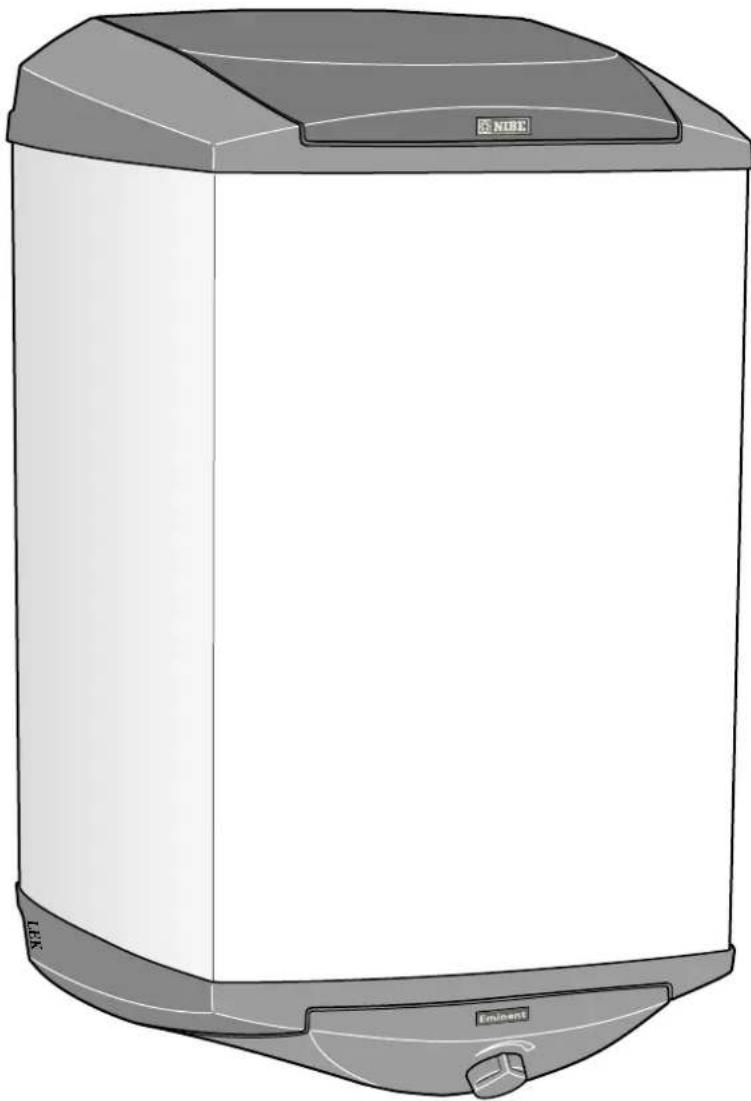
natural_image
Illustration of a NIBE water heater with no visible text or symbols on the bodyMONTERINGS- OCH SKÖTSELANVISNING
EMINENT
E/CU/R 35, 55, 100, 120
3 Plastlock, anod (EMINENT-E)
natural_image
Hand holding a tool applying material to a circular object (no text or symbols visible)Tömning
natural_image
Line drawing of a hand pointing at a device with a circular base and arrow, no text or symbols presentTyhjennys
Anturien asennus
Dimensions and location of components
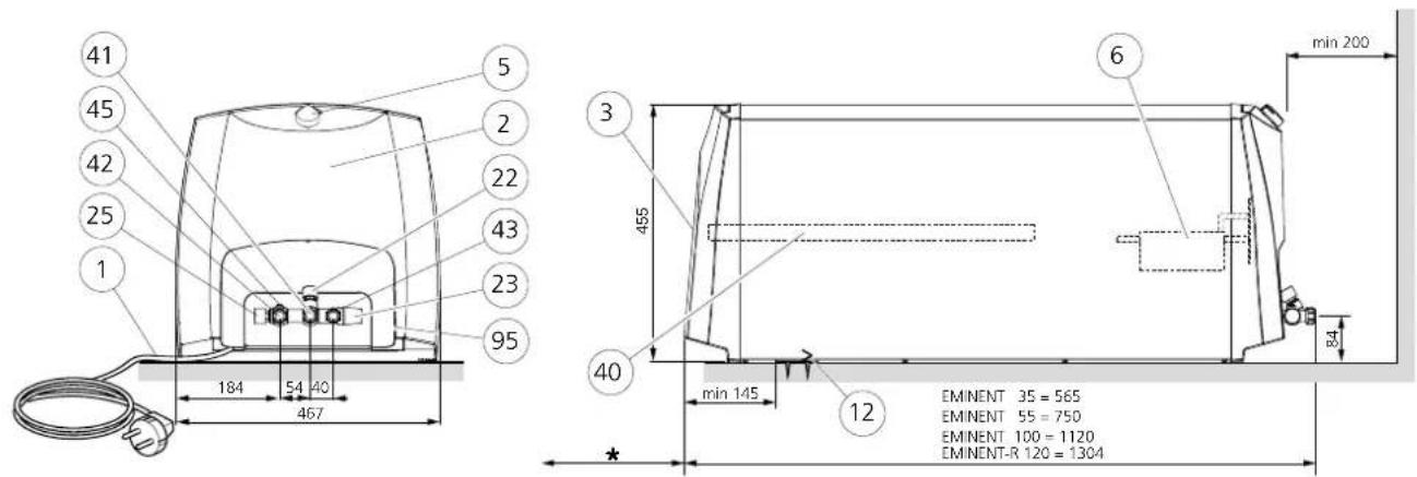
* Required space (EMINENT-E) for replacing/checking the sacrificial anode.
35 litres: 180 mm
55 litres: 250 mm
100 litres: 390 mm
The chain anode can be used for vertical hanging installation, which only requires 180 mm above the water heater.
The serial number (95), should always be stated with all correspondence with NIBE.
072
List of components
1 Power cord with earthed plug, length 850 mm
2 Plastic cover, electrical connection box
3 Plastic cover, anode (EMINENT-E)
5Thermostat/temperaturelimiter
6Immersionheater
12Hangingbracket
13Securingbracket
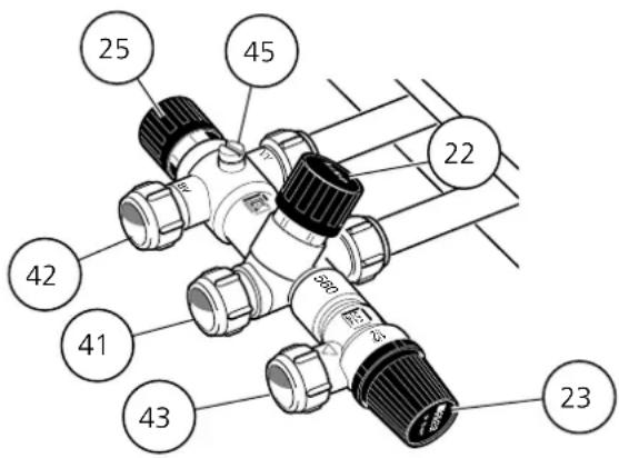
22Shutoff/non-returnvalve
23 Safety/drainage valve
25 Mixing valve
40 Sacrificial anode (EMINENT-E)
41 Cold water connection, compression fitting ∅15 mm
42 Hot water connection, compression fitting ∅15 mm
43 Connection safety/drainage valve, compression ring coupling ∅15 mm
45 Venting screw (for air supply when draining)
95 Serial number sticker
This appliance can be used by children aged from 8 years and above and persons with reduced physical, sensory or mental capabilities or lack of experience and knowledge if they have been given supervision or instruction concerning use of the appliance in a safe way and understand the hazards involved. Children shall not play with the appliance. Cleaning and user maintenance shall not be made by children without supervision.
Rights to make any design or technical modifications are reserved.
©NIBE 2015.
Installation
Mounting
It is recommended that the water heater is installed in a room with existing floor drainage. The water heater can be mounted hanging vertically on a flat surface (with the connections downward) or lying horizontally (with the reverse down).
Use the supplied suspension brackets (12) when hanging on a wall, these are secured first ( 8 - 10 mm screws), see the figure below. The water heater is then mounted on the bracket. The water heater can now be slid sideways to some extent, which facilitates the fitting of the pipes.
For further fastening, the enclosed securing bracket (13) is fitted on the wall against the top of the water heater as a tip guard, see the figure below.
An area of 200 mm is required in front of/under the water heater for service work.
* EMINENT-E requires free space behind /above the water heater for inspection of the sacrificial anode (40). See the section "Care and maintenance - Sacrificial anode".
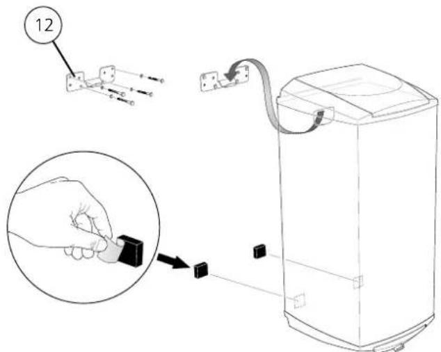
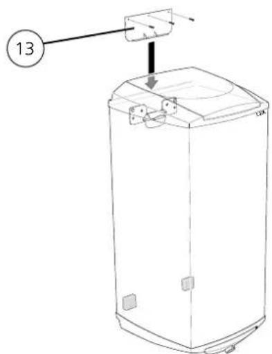
Pipe installation
The water heater is equipped for compression ring couplings for copper or plastic pipes. Internal support bushes should be fitted when a plastic or annealed copper pipe is used.
All necessary valve equipment: shut-off/non-return valve, safety/drain valve and the mixing valve installed on delivery.
An overflow pipe should be routed from the safety valve to an appropriate drain. The dimension of the overflow pipe must be the same as the safety valve's, (∅15 mm), the pipe must be routed to prevent water pockets, and be frost-proof and well supported.
If uncertain contact pipe installer alternatively see applicable standards.
If the hot water heater is installed without a mixing valve, the thermostat setting must be such that the tap water temperature does not exceed 65 °C. Should a higher temperature be required, follow the applicable directions.
Filling
The water heater must be filled with water before the mains supply is switched on. Filling takes place as follows:
1 Check that the bleed screw°(45) is tightened.
2 Check that the safety/drainage valve (23) is closed.
3 Open the shut off valve by turning the knob (22) anti-clockwise.
4 Bleed the water heater by opening a hot water tap in the system. When only water comes out of the tap this can be closed.
The water heater is now filled and the power can be switched on.
Setting the mixing valve
Increase/decrease the tap water temperature by turning the mixing valve knob (25) anti-clockwise/clockwise. Setting range approx. 50 – 65°C.
Electrical installation
NOTE!
Electrical installation and service must be carried out under the supervision of a qualified electrician.
The water heater is connected to an earthed socket power cord for 1 phase installation (1 kW).
1-phase installation provides the best service life for the immersion heater.
If the power cable is damaged, replacement must be carried out under the supervision of a qualified electrician.
The lowest point of the power cord should be below the power socket when you connect the hot water heater to the socket. This prevents any drops of water from being led into the socket.
If 3 kW is required hot water heater is connected with fixed installation (2x400V). At fixed installation the water heater is preceded by an isolator (at least with signal lamp) with at least 3 mm breaker gap. Existing connection cable can be used if one cuts off the plug.
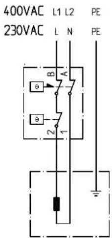
Electrical circuit diagram
Thermostat/temperature limiter (5)
Immersion heater (6)
Installing a thermostat
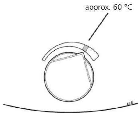
A setting of 60\ °C (max about 80\ °C ) is recommended for the best operating conditions.
Maintenance
Safety valve
The safety valve (23) must be inspected regularly, about 4 times a year, to prevent clogging. The check is made by turning the safety valve's knob anticlockwise, water should then flow through the overflow pipe. If this does not happen then the safety valve is defective and must be replaced.
The safety valve sometimes releases a little water after hot water has been used. This discharge is caused by the expansion of cold water entering the water heater, resulting in a pressure increase, whereby the safety valve opens.
Sacrificial anode (only EMINENT-E)
The water heater is equipped with a magnesium anode (40) that provides extra corrosion protection. The anode is used partly because it sacrifices itself for pores in the enamel, partly because it uses itself depending on the chemical composition of the water.
Check the anode within a year. Then regularly in relation to its use. When the anode is new it has a diameter of approx. 21 mm. When this diameter has reduced, in the most consumed area, to less than 10mm the anode is consumed and must be replaced.
If the anode has not been consumed after a few years, it may be due to poor conductivity in the water and a water analysis is recommended.
NOTE!
The anode is a consumable.
Replacing/checking the sacrificial anode
The anode can be replaced/checked, without the water heater needing to be emptied, if there is a hot water tap in the pipe system situated below the water heater's highest point. If there is not a hot water tap or the water heater is installed horizontally it must be drained, see section "Draining".
1 Turn off the power to the water heater.
2 Open the shut off valve/ non-return valve by turning the knob (22) clockwise until it bottoms.
3 Open the hot water tap mentioned above.
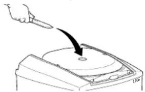
4 Remove the plastic cover (3) and the insulation plug, see image.
5 The sacrificial anode (40) is unscrewed using the 27 mm, or 24 mm, socket.
When replacing the anode in tight spaces, a chain anode is available that only requires approx. 180 mm space above the water heater. The chain anode can only be used in vertically mounted water heaters and must be cut according to the table, see "Technical data".
natural_image
Hand holding a pen striking a circular object on a base (no text or symbols visible)Emptying
Draining is through the safety valve overflow pipe and is carried out as follows:
1 Turn off the power to the water heater.
2 Open the shut off valve/ non-return valve by turning the knob (22) clockwise until it bottoms.
3 Turn the mixer valve (25) fully anticlockwise.
4 Open the safety valve by turning the knob (23) slowly anticlockwise a quarter of a turn until it is fixed in the raised position.
NOTE!
Water splashes may occur at the overflow pipe.
5 Remove the vent screw (45) and open the hot water tap positioned lowest in the pipe system.
NOTE!
Hot water may squirt out of the air screw hole.
It can take a few minutes for draining to start.
To speed draining, air can be introduced via the vent screw (45).
Keep the valves' positions after the above actions until the water heater is to be used again.
A small amount of water may remain at the bottom of the water heater after performing draining stages 1–5.
NOTE!
The overflow pipe must be connected to pos (43).
Dealing with malfunctions
NOTE!
Electrical installation and service must be carried out under the supervision of a qualified electrician.
If the power cable is damaged, in order to prevent a hazard it must be replaced by the manufacturer, its authorised service agent or other qualified person.
Check the installation's fuses as well as the thermostat and mixer valve settings.
Wait a few hours without tapping any hot water and then check whether the temperature level has risen. If there is still no hot water, contact the installation engineer.
Resetting the temperature limiter
If the temperature limiter (5) tripped, the water heater must cool for at least one hour before it can be reset.
- Remove the plastic cover (2).
- Press the button on the temperature limiter lightly, max 15 N (approx. 1.5 kg).
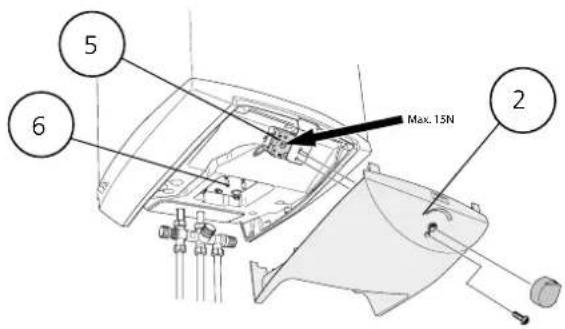
Max 15 N (approx. 1.5 kg)
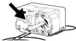
Reconnecting sensors
If the immersion heater has been replaced, the sensors for the thermostat and temperature limiter must be re-installed in the order displayed in the image.

Service
For service, contact the installer. The serial number (95), (14 digits) and installation date should always be stated. Only electrical equipment supplied by NIBE AB in Markaryd may be used.
Technical specifications

IP 24 PED 97/23/EC
| Volume (litres) 35 55 100 120 | |||||
| Max workingpressure (MPa/bar) 0,9/9 | |||||
| Voltage 230 VAC + PE / 2 x 400 VAC | + PE | ||||
| Enclosure class IP 24 | |||||
| Output (kW) 1/3 | |||||
| Fuses required at 1/3 kW (A) 6/10 | |||||
| Heating time to 45 °C at 1/3 kW* | (hours) | 1,4/0,5 | 2,3/0,8 | 4,1/1,4 | 4,9/1,6 |
| Heating time to 80°C at 1/3 kW* | (hours) | 2,9/1,0 | 4,5/1,5 | 8,1/2,7 | 10,1/3,5 |
| Net weight E/CU/R | (kg) | 19/21/17 | 25/28/22 | 36/40/31 | -/-/34 |
| Sacrificial anode EMINENT-E | (mm) | 165 | 280 | 435 | - |
| Corrosion protection EMINENT-E | Enamel | - | |||
| Corrosion protection EMINENT-CU | Copper | - | |||
| Corrosion protection EMINENT-R | Stainless | ||||
* With incoming cold water of 10 °C.
Energy labelling
| Supplier | NIBE AB | ||||
| Model | EVH 16 - 35 | EVH 16 - 55 | EVH 16 - 100 | EVH 16 - 120 | |
| Declared load profile | S | M | L | -/-/L | |
| Water heating energy efficiency class E/CU/R | C/C/B | C/C/C | C/C/C | -/-/C | |
| Water heating energy efficiency, ηvh E/CU/R | % | 34,2/33,7/35,6 | 36,5/36,5/37,0 | 37,3/37,3/38,1 | -/-/37,8 |
| Annual energy consumption water heating, AEC E/CU/R | kWh | 539,6/547,8/518,6 | 1406,8/1407,7/1389,1 | 2748,3/2745,8/2688,9 | -/-/2709,8 |
| Thermostat setting | °C | 60 | |||
| Daily electrical consumption, Qelec E/CU/R | kWh | 2,56/2,61/2,44 | 6,57/6,58/6,47 | 12,77/12,76/12,54 | -/-/12,54 |
| Amount of hot water (40 °C), V40 E/CU/R | l | 47/46/43 | 78/77/71 | 140/141/135 | -/-/167 |
| Sound power level LW/A | dB | 15 | |||
| Applied standards | EN 50440 | ||||
INSTALLATIE- EN ONDERHOUDSINSTRUCTIES
EMINENT
E/CU/R 35, 55, 100, 120
NIBE Energy Systems Ltd, 3C Broom Business Park, Bridge Way, Chesterfield S41 9QG
Tel: 0845 095 1200 Fax: 0845 095 1201 E-mail: info@nibe.co.uk www.nibe.co.uk

NIBE Energietechniek B.V., Postbus 634, NL 4900 AP Oosterhout
Tel: 0168 477722 Fax: 0168 476998 E-mail: info@nibenl.nl www.nibenl.nl

© "EVAN" 17, per. Boynovskiy, Nizhny Novgorod
Tel./fax +7 831 419 57 06 E-mail: info@evan.ru www.nibe-evan.ru



- MONTERINGS- OCH SKÖTSELANVISNING
- EMINENT
- Tömning
- Tyhjennys
- Anturien asennus
- Dimensions and location of components
- List of components
- Installation
- Mounting
- Pipe installation
- Filling
- Setting the mixing valve
- Electrical installation
- NOTE!
- Electrical circuit diagram
- Installing a thermostat
- Maintenance
- Safety valve
- Sacrificial anode (only EMINENT-E)
- Replacing/checking the sacrificial anode
- Emptying
- Dealing with malfunctions
- Resetting the temperature limiter
- Reconnecting sensors
- Service
- INSTALLATIE- EN ONDERHOUDSINSTRUCTIES
Brand : Nibe
Model : Eminent 35 R
Category : Central heating boiler