
Eminent 100 R - Central heating boiler Nibe - Free user manual and instructions
Find the device manual for free Eminent 100 R Nibe in PDF.


| Product Type | Central Heating Boiler (Water Heater) |
| Brand | NIBE |
| Model | Eminent 100 R |
| Volume | 100 liters |
| Dimensions (L x Ø?) | L=1120 mm (vertical installation) |
| Weight | 36 kg (E), 40 kg (Cu), 31 kg (R) net |
| Power Supply | 230 VAC + PE / 2 x 400 VAC + PE |
| Heating Output | 1 kW or 3 kW (selectable) |
| Max Cut-off Pressure | 0.9 MPa / 9 bar |
| Enclosure Class | IP24 |
| Thermostat Setting Range | Approx. 50°C – 65°C (mixer valve); max 80°C (immersion heater) |
| Heating Time to 45°C (1/3 kW) | 4.1 h / 1.4 h |
| Heating Time to 80°C (1/3 kW) | 8.1 h / 2.7 h |
| Water Heating Energy Efficiency Class | C (for 100R model) |
| Corrosion Protection | Stainless steel (R model) |
| Sacrificial Anode | Not present in R model; stainless steel tank |
| Safety Features | CE marked, temperature limiter, safety/drain valve, shut-off/non-return valve |
| Installation Type | Vertical wall-hung or horizontal |
| Connections | Cold/hot water: compression ring coupling ∅15 mm; overflow pipe: same as safety valve ∅15 mm |
| Maintenance | Check safety valve 4x/year; drain via safety valve; for E/Cu models check/replace anode annually |
| Spare Parts / Reparability | Thermostat, immersion heater, temperature limiter, safety valve, mixer valve available |
Frequently Asked Questions - Eminent 100 R Nibe
User questions about Eminent 100 R Nibe
0 question about this device. Answer the ones you know or ask your own.
Ask a new question about this device
Download the instructions for your Central heating boiler in PDF format for free! Find your manual Eminent 100 R - Nibe and take your electronic device back in hand. On this page are published all the documents necessary for the use of your device. Eminent 100 R by Nibe.
USER MANUAL Eminent 100 R Nibe
GB User and Installer manual Eminent
natural_image
Product display featuring three white industrial devices and a gray tool icon, with NIBE logo in corner (no text or symbols on main objects)Table of Contents
Svenska
____ ____ ____
4Viktig information
5Användarhandbok
This manual describes installation and service ures for implementation by specialists.
The manual must be left with the customer.
The serial number can be found on the underside of product. proced-

Caution
Always give the product's serial number when reporting a fault.
This appliance can be used by children
aged from 8 years and above and with reduced physical, sensory or
capabilities or lack of experience and
knowledge if they have been given vision or instruction concerning use
appliance in a safe way and under the hazards involved. Children shall
play with the appliance. Cleaning a maintenance shall not be made by without supervision.
Rights to make any design or technical modi cations are reserved.
©NIBE 2018.
persons RECOVERY ental

Leave the disposal of the packaging to the in staller who installed the product or to special waste stations.

Do not dispose of used products with normal household waste. It must be disposed of at a waste station or dealer who provides this typ
children disposal of the product by the user results administrative penalties in accordance with current legislation.
SYMBOLS

NOTE
This symbol indicates danger to person or machine.

Caution
This symbol indicates important information about what you should observe when maintaining your installation.
MARKING
CE The CE mark is obligatory for most products sold in the EU, regardless of where they are made.
IP24 Classi cation of enclosure of electro-technical equipment.
INSPECTION OF THE INSTALLATION
Current regulations require the heating installation to be inspected before it is commissioned. The ins be carried out by a suitably qualified person.
| √ | DateSignat | |||
| Hot water (page 16) | ||||
| Shut off valves | ||||
| Cold water (page 16) | ||||
| Shut off valves | ||||
| Non-return valve | ||||
| Mixing valve | ||||
| Safety valve | ||||
| Electricity (page 14) | ||||
| Connected supply | ||||
ureNotesDe
User manual
MAINTENANCE
SAFETY VALVE

NOTE
The anode is a consumable.
REPLACING/CHECKING THE SACRIFICIAL
ANODE
The safety valve (FL1) must be inspected regularly, about
4 times a year, to prevent clogging. The check is made by turning the safety valve's knob anticlockwise, water should then ow through the over ow pipe. If this does not happen, then the safety valve is defective and must be replaced. If there is a hot water tap in the pipe system situ below the water heater's highest point, the anode can be replaced/checked, without the water heater needing to be emptied. If there is not a hot water tap or ter heater is installed horizontally it must be drained,
The safety valve sometimes releases a little water after hot water has been used. This discharge is caused by see section Draining. Turn off the power to the water heater.
the expansion of cold water entering the water heater. Open the shut off valve/non-return valve by turning resulting in a pressure increase, whereby the safety the knob (QM35) clockwise until it bottoms. valve opens.
SACRIFICIAL ANODE (ONLY EMINENT-E)
- Open the hot water tap mentioned above.
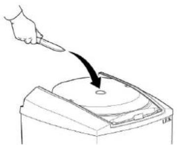
The water heater is equipped with a magnesium anode. Remove the plastic cover (QQ4) and the insulation (FR2) that provides extra corrosion protection. The plug, see image.
is consumed partly because it sacri ces itself for the pores in the enamel and partly because it consumes itself, or 24 mm, socket wrench.
depending on the chemical composition of the water.
Check the anode within a year. Then check regularly, in relation to its use. When the anode is new, it has a diameter of approx. 21 mm. When this diameter has reduced, in the most consumed area, to less than 10 mm, the anode is consumed and must be replaced.
If there is no anode consumption after a few years, this could be due to poor conductivity in the water and analysis of the water is recommended.
natural_image
Line drawing of a hand holding a knife striking a circular object on a machine (no text or symbols)EMPTYING
Draining is through the safety valve over ow pipe and is carried out as follows:
- Turn off the power to the water heater.
- Open the shut off valve/non-return valve by the knob (QM35) clockwise until it bottoms.
- Turn the mixer valve (FQ1) fully anticlockw
- Open the safety valve by turning the knob anticlockwise a quarter of a turn, until it is raised position.

NOTE
Water splashes may occur at the overflo
- Remove the vent screw (QM5) and open tap positioned lowest in the pipe system.

NOTE
Hot water may squirt out of the vent hole.
It can take a few minutes for draining to start work.
To speed up draining, air can be introduced screw (QM5).
Keep the valves' positions after the above actions until
the water heater is to be used again.
A small amount of water may remain at the bottom of the water heater after the draining stages described -1 -5.

NOTE
The over ow pipe must be connected to pos. (XL48).

turning Installer manual
INSTALLATION
MOUNTING
The water heater must be installed in a room with ing oor drainage. The water heater can be mounted hanging vertically on a at wall (with the connections downward) or horizontally (with the rear facing down).
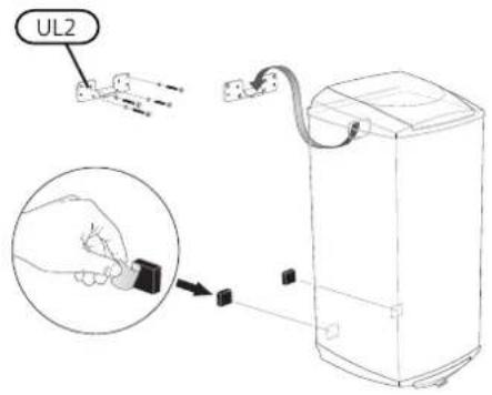
ow/sep the enclosed suspension bracket (UL2) when hanging on a wall; this is set up rst (∅8 - 10 r (crevo), water the dimensions diagram and gure below). The water heater is then hung on the bracket. The heater can now slide sideways a little, which facilitates the installation of the pipes. To secure further, the closed securing bracket (UL3) is mounted on the wall against the top of the water heater as a tip guard, the gure below. An area of 200 mm free space is quired in front of/under the water heater for servicing tavork.
via EMtheNTventquires free space behind/above the water heater for inspection of the sacrificial anode (FR2). See the section "Care and main
ance - Sacri cial anode'.


NOTE
For suspended installation, these spacers must be glued onto the heater to keep it parallel with

PIPE INSTALLATION
Pipe installation must be carried out in accordance current norms and directives.
The water heater is supplied with compression ring couplings for copper or plastic pipes. Internal support bushes must be fitted when a plastic or annealed pipe is used.
All necessary valve equipment: the shut-off/non-return valve, the safety/drain valve and the mixer valve a stalled on delivery.
When the water heater is installed without a Thier water, heater is supplied with a power cable with the thermostat setting must be such that the earthwater plug for 1 phase installation (1 kW). 1 phase temperature does not exceed 65 °C. Should astallighen provides the best service life for the immers temperature be required, follow the relevant directions
for the application.
An over ow pipe must be routed from the safety valve socket when you connect the water heater to a suitable drain. The dimension of the over ow the pipe socket. This prevents any drops of water from must be the same as the safety valve's (015 being) led into the socket.
pipe must be routed to prevent water pocket: frost-proof and well supported.
If uncertain, contact a plumber alternatively see able standards.
For more information see nibe.eu.

NOTE
Ensure that incoming water is clean. When using a private well, it may be necessary to supplement with an extra water liter.
Filling
The water heater must be lled with water before t mains supply is switched on. Filling takes place as t lows:
- Check that the vent screw (QM5) is tightened.
- Check that the safety/drainage valve (FL1) is closec
- Open the shut off valve by turning the knob (ON) on clockwise.
the Bivwall.the water heater by opening a hot water 1 the system. This can be closed when only water comes out of the tap. The water heater is now and the power can be switched on.
Setting the mixer valve
Increase/decrease the tap water temperature by turning the mixer valve knob (FQ1) anti-clockwise/clockwise.
Setting range approx. 50 - 65 °C.
ELECTRICAL INSTALLATION

NOTE
Electrical installation and service must be carried out under the supervision of a qualified electrician, and in accordance with applicable electrical safety regulations.
If the power cable is damaged it must be replaced by the manufacturer, its authorised service agent or another qualified person, in order to prevent a hazard.
The lowest point of the power cable should be belc safety power socket when you connect the water heater to the pipoet. This prevents any drops of water from being) led to the socket.
If 3 KW is required, the water heater must be connected as a permanent installation (2x400V). For permanent installation, the water heater is preceded by an isolator (preferably with a signal lamp) with at least 3 mm breaker gap. The existing power can be used if the plug is cut off.
Electrical circuit diagram


Setting thermostat
For best operating conditions, we recommend a setting of 60 °C (max approx. 80 °C).

DEALING WITH MALFUNCTIONS

NOTE
Electrical installation and service must be carried out under the supervision of a qualified electrician, and in accordance with applicable electrical safety regulations.
If the power cable is damaged it must be replaced by the manufacturer, its authorised service agent or another Service qualified person, in order to prevent service a hazard. (14 digits)

Reconnecting sensors
If the immersion heater has been replaced, the sense for the thermostat and temperature limiter must be r installed in the order shown in the image.

vent service, contact the installer. The serial number (P (14 digits) and installation date should always be stat Only electrical equipment supplied by NIBE AB in Markand may be used.
Check the installation's fuses as well as the and mixer valve settings.
Wait a few hours without hot water usage and then check whether the temperature level has risen. If there is still no hot water, contact the installation engineer.
Resetting the temperature limiter
If the temperature limiter (FD1) tripped, the water heater must cool for at least one hour before it can be reset.
- Turn off the power to the water heater
- Remove the plastic cover (QQ3).
- Press the button on the temperature limiter lightly, max 15 N (approx. 1,5 kg).
TECHNICAL DATA
COMPONENT LOCATION, DIMENSIONS AND SETTING-OUT COORDINATES

List of components
FD1 Thermostat/temperature limiter
EB1 Immersion heater
UL2 Hanging bracket
FL1 Safety/drainage valveX1 Power cable with earthed plug,
FQ1 Mixer valveQQ3 Plastic cover, junction box
FR2 Sacri cial anode (EMINENT- E)QQ4 Plastic cover, anode
XL3 Cold water connection, compression ring coupling ∅15 mm
XL4 Hot water connection, compression ring coupling ∅15 mm
XL48 Connection safety/draining valve, compression ring coupling ∅15 mm
QM5 Vent screw (for air supply during draining)UL3 Securing
PF3 Serial number plateQM35 Shutoff/non-return valve
Dimensions and setting-out coordinates
Eminent 35 litres:180 mm
Eminent 55 litres:250 mm
Eminent 100 litres:390 mm
L=Total length water heater.*Required space (EMINENT-E) for replacing/checking the
Eminent 35: L=565 mm
Eminent 55: L=750 mm
Eminent 100: L=1120 mm
Eminent -R 120: L=1304 mm
When installed hanging vertically, the chain anode, which only requires 180 mm above the water h used.
| 1 E/Cu/R | 1201005535Model | ||||||
| 2 ef ciency class E/Cu/R | -/-/LLMSDeclared tar. | ||||||
| -/-/CC/C/CC/C/CC/C/Bt | |||||||
| 1201005535Volume | |||||||
| MPa/barMax cut-off pressure 0,9/9 | pressure | ||||||
| Voltage | 230 VAC + PE / 2 x 400 VAC + PE | ||||||
| Enclosure class | IP24 | ||||||
| Output | kW | 1/3 | |||||
| Fuses required at 1/3 kW | A | 6/10 | |||||
| Heating time to 45 °C 1/3 kW 3 | h | 1,4/0,5 | 2,3/0,8 | 4,1/1,4 | 4,9/1,6 | ||
| Heating time to 80 °C 1/3 kW 3 | h | 2,9/1,0 | 4,5/1,5 | 8,1/2,7 | 10,1/3,5 | ||
| 4 | 22518510060lHot w. | ||||||
| Net weight E/Cu/R | kg | 19/21/17 | 25/28/22 | 36/40/31 | -/-/34 | ||
| Length sacri cial anode Eminent E | mm | 165 | 280 | 435 | - | ||
| Corrosion protection Eminent E | Enamel | - | |||||
| Corrosion protection Eminent Cu | Copper | - | |||||
| Corrosion protection Eminent R | Stainless | ||||||
| RSK no. Eminent E | 694 43 10 | 694 43 11 | 694 43 12 | - | |||
| RSK no. Eminent Cu | 694 43 13 | 694 43 14 | 694 43 15 | - | |||
| RSK no. Eminent R | 694 43 16 | 694 43 17 | 694 43 18 | 694 43 19 | |||
1 Scale for declared tap pro le 3XS - 4XL
2 Scale for hot water heating efficiency class A+ - F.
3 For incoming cold water at 10irc C
4Applies to suspended installation and to an incoming cold water temperature of 10ircC , outgoing hot water temperature of 40ircC , a tap ow of 12 litres per minute and a thermostat setting of 75ircC . In the case of horizontal installation, the hot water capacity is approx. 15% less.
ENERGY LABELLING
| Supplier | NIBE AB | ||||
| Model | EVH 16 - 35E/CU/R | EVH 16 - 55E/CU/R | EVH 16 - 100E/CU/R | EVH 16 - 120E/CU/R | |
| Declared load pro le | S | M | L | - / - / L | |
| Water heating energy ef ciency class | C/C/B | C/C/C | C/C/C | - / - / C | |
| Water heating energy ef ciency, ηwh | % | 34,2/33,7/35,6 | 36,5/36,5/37,0 | 37,3/37,3/38,1 | - / - / 37,8 |
| Annual energy consumption water heating, AEC | kWh | 540/548/519 | 1407/1408/1389 | 2748/2746/2689 | - / - / 2710 |
| Quantity 40-degree hot water, V40 | l | 47/46/43 | 78/77/71 | 140/141/135 | - / - / 167 |
| Thermostat setting | °C | 60 | 60 | 60 | 60 |
| Daily electrical consumption, Qelec | kWh | 2,56/2,61/2,44 | 6,57/6,58/6,47 | 12,77/12,76/12,54 | - / - / 12,54 |
| Sound power level LWA | dB | 15 | 15 | 15 | 15 |
| Applied standards | EN 50440 | ||||
Suomeksi
Tärkeää
TURVALLISUUSTIEDOT
natural_image
Line drawing of a hand holding a knife striking a circular object on a machine (no text or symbols)TYHJENNYS
Anturien asennus
-/-/CC/C/CC/C/CC/C/BH
1201005535|Tilavuus
OPOFFERINGSANODE (ALLEEN EMINENT
natural_image
Line drawing of a hand holding a knife striking a circular object on a machine (no text or symbols)SYSTEEM LEEGMAKEN
This manual is a publication from NIBE Energy Systems. All product illustrations speci cations are based on current information at the time of the publication's NIBE Energy Systems makes reservations for any factual or printing errors in




- Table of Contents
- Caution
- persons RECOVERY ental
- SYMBOLS
- NOTE
- MARKING
- INSPECTION OF THE INSTALLATION
- User manual
- MAINTENANCE
- SAFETY VALVE
- REPLACING/CHECKING THE SACRIFICIAL
- ANODE
- SACRIFICIAL ANODE (ONLY EMINENT-E)
- EMPTYING
- turning Installer manual
- INSTALLATION
- MOUNTING
- PIPE INSTALLATION
- Filling
- Electrical circuit diagram
- Setting thermostat
- DEALING WITH MALFUNCTIONS
- Reconnecting sensors
- Resetting the temperature limiter
- TECHNICAL DATA
- COMPONENT LOCATION, DIMENSIONS AND SETTING-OUT COORDINATES
- List of components
- Dimensions and setting-out coordinates
- Suomeksi
- Tärkeää
- TURVALLISUUSTIEDOT
- TYHJENNYS
- Anturien asennus
- OPOFFERINGSANODE (ALLEEN EMINENT
- SYSTEEM LEEGMAKEN
Brand : Nibe
Model : Eminent 100 R
Category : Central heating boiler