
Lynton 53050 - Fan HONEYWELL - Free user manual and instructions
Find the device manual for free Lynton 53050 HONEYWELL in PDF.

| Product Type | Ceiling Fan |
| Brand | Honeywell |
| Model | Lynton 53050 |
| Usage | Indoor or Damp Locations |
| Number of Blades | 3 |
| Net Weight | 9.44 kg |
| Minimum Floor Height | 2.13 m |
| Minimum Side Clearance | 76.2 cm |
| Maximum Ceiling Angle | 10° |
| Power Supply | 120 V~, 60 Hz (hardwired) |
| Light Power | 23 W (integrated LED) |
| Color Temperature | 2200 K - 6500 K (adjustable) |
| Number of Speeds | 6 |
| Reverse Function | Yes (summer/winter) |
| Control Type | Remote control with receiver |
| Remote Control Batteries | 2 AAA 1.5 V batteries (alkaline) |
| Special Features | Timer 2/4/8 h, Home Shield, variable breeze, delayed light shut-off |
| Materials | Metal and plastic (durable quality) |
| Cleaning | Lint-free cloth, soft brush |
| Motor Warranty | Lifetime (limited) |
| Parts Warranty | 1 year |
Frequently Asked Questions - Lynton 53050 HONEYWELL
User questions about Lynton 53050 HONEYWELL
0 question about this device. Answer the ones you know or ask your own.
Ask a new question about this device
Download the instructions for your Fan in PDF format for free! Find your manual Lynton 53050 - HONEYWELL and take your electronic device back in hand. On this page are published all the documents necessary for the use of your device. Lynton 53050 by HONEYWELL.
USER MANUAL Lynton 53050 HONEYWELL
Read and save these instructions before use
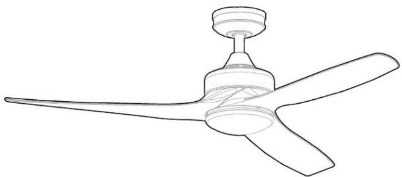
natural_image
Line drawing of a three-blade propeller with a central hub and spout (no text or symbols)Model #53050
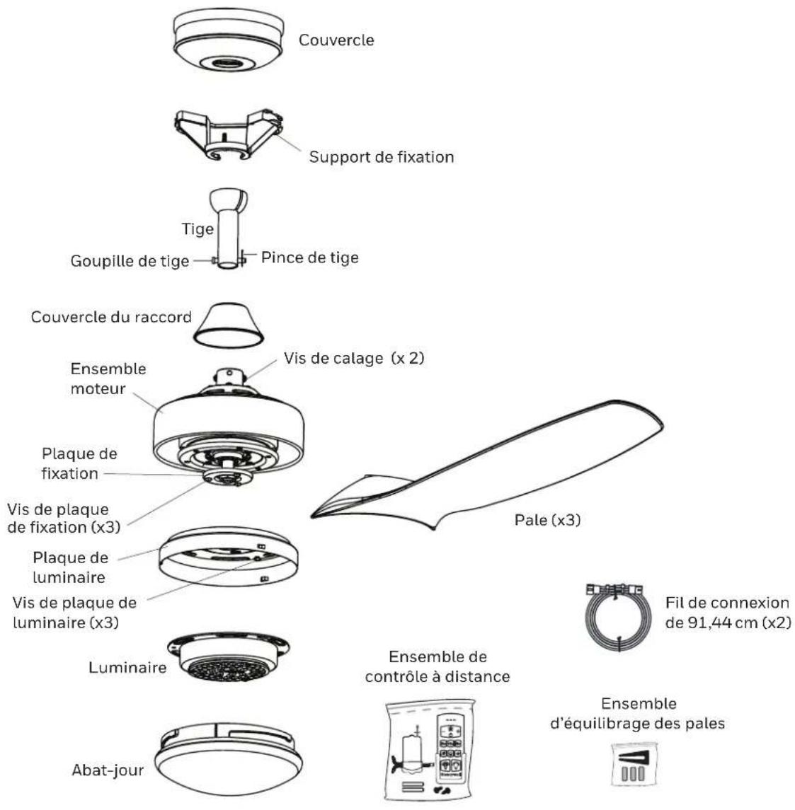
PACKAGE CONTENTS
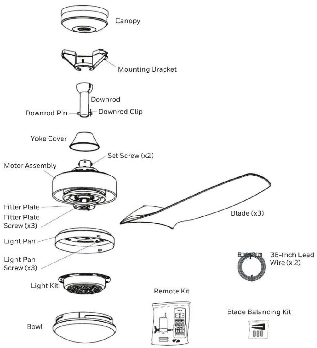
HARDWARE CONTENTS
Note: Some extra hardware may be included. The quantity listed above is the number required for installation.
THANK YOU
Honeywell Ceiling Fans feature a collection of fans in various sizes and specifications to ensure your choice of indoor or outdoor fan delivers optimum performance for your room's size. You can trust the quality of Honeywell Ceiling Fans to deliver maximum airflow and stylish lighting options. Honeywell Ceiling Fans use high-quality materials that are long lasting and durable to deliver a great look and last for years to come.
SAFETY INFORMATION
Please read and understand this entire manual before attempting to assemble, operate or install the product.
- Before you begin installing the fan, disconnect the power by removing fuses or turning off the circuit breakers.
- Make sure all electrical connections comply with local codes, ordinances, the National Electrical Code and ANSI/NFPA 70-199. Hire an electrician or consult a do-it-yourself handbook if you are unfamiliar with installing electrical wiring.
- Make sure the installation site you choose allows a minimum of 7 feet from the blades to the floor and at least 30 inches from the tip of the blades to any obstruction.
- RATED FOR DAMP LOCATIONS. This fan is intended for indoor or damp locations. It is not suitable for outdoor locations.
• The weight of the fan is 21.56 pounds.
DANGER: When using an existing outlet box, make sure it is securely attached to the building structure and can support the full weight of the fan. Failure to this can result in serious injury or death. The stability of the outlet box is essential in minimizing wobble and noise in the fan after installation is complete.
WARNING: To avoid personal injury, the use of gloves may be necessary while handling fan parts with sharp edges.
WARNING: Using a full-range dimmer switch to control fan speed will cause a humming sound from the fan. To reduce the risk of fire or electric shock, do NOT use a full-range dimmer switch to control fan speed.
WARNING: To reduce the risk of fire, electric shock or personal injury, mount the fan to an outlet box marked "ACCEPTABLE FOR FAN SUPPORT" and use the mounting screws provided with the outlet box. Most outlet boxes commonly used for the support of lighting fixtures are not acceptable for fan support and may need to be replaced. Consult a qualified electrician if in doubt. Secure the outlet box directly to the building structure. The outlet box and its support must be able to support the moving weight of the fan (at least 35 lbs.).
WARNING: To reduce the risk of fire, electric shock or personal injury, wire connectors provided with this fan are designed to accept only one 12-gauge house wire and two lead wires from the fan. If your house wire is larger than 12-gauge and/or there is more than one house wire to connect to the two fan lead wires, consult an electrician for the proper size wire connectors to use.
WARNING: To reduce the risk of fire, electric shock or personal injury, do not bend the blade arms when installing them, balancing the blades or cleaning the fan. Do not insert objects between the rotating fan blades.
WARNING: To reduce the risk of personal injury, use only parts provided with this fan. The use of parts other than those provided with this fan will void the warranty.
CAUTION: Be sure the outlet box is properly grounded or a ground (green or bare) wire is present.
CAUTION: Carefully check all screws, bolts, and nuts on the fan assembly ensure they are secured.
SAFETY INFORMATION
CAUTION: This device complies with Industry Canada license-exempt RSS standard(s). Operation is subject to the following two conditions: (1) this device may not cause interference, and (2) this device must accept any interference, including interference that may cause undesired operation of the device (if applicable).
CAN ICES-003 (B) / NMB-003 (B)
CAN ICES-005 (B) / NMB-005 (B)
This device complies with Part 15 of the FCC Rules. Operation is subject to the following two conditions: (1) this device may not cause harmful interference, and (2) this device must accept any interference received, including interference that may cause undesired operation.
This equipment has been tested and found to comply with the limits for a Class B digital device, pursuant to Part 15 of the FCC Rules. These limits are designed to provide reasonable protection against harmful interference in a residential installation. This equipment generates, uses and can radiate radio frequency energy and, if not installed and used in accordance with the instructions, may cause harmful interference to radio communications. However, there is no guarantee that interference will not occur in a particular installation. If this equipment does cause harmful interference to radio or television reception, which can be determined by turning the equipment off and on, the user is encouraged to try to correct the interference by one or more of the following measures:
--Reorient or relocate the receiving antenna.
--Increase the separation between the equipment and receiver
--Connect the equipment into an outlet on a circuit different from that to which the receiver is connected.
--Consult the dealer or an experienced radio/TV technician for help.
Please note changes or modifications not expressly approved by the party responsible for compliance could void the user's authority to operate the equipment.
HKC-US
3350 Players Club Parkway #225
Memphis, TN 38125
1-877-361-3883
CARE AND MAINTENANCE
At least twice each year, lower the canopy to check the downrod assembly and tighten all screws on the fan. Clean the motor housing and blades with a soft brush or lint-free cloth to avoid scratching the finish.
Total fixture wattage is 23 watts; do not attempt to replace.
Battery Replacement: Use 1.5 V, AAA alkaline batteries. WARNING: Keep batteries out of reach of children. May be fatal if swallowed. In the event that a battery is swallowed, immediately consult a doctor. Non-rechargeable batteries are not to be recharged. Do not mix different types of batteries such as alkaline, carbon-zinc, or rechargeable batteries. Do not mix old and new batteries. Batteries are to be inserted with the correct polarity. Exhausted batteries are to be removed from the product. Do not dispose of batteries in fire, as they may explode or leak.
Important: Shut off the main power supply before you begin any maintenance task. Do NOT use water or a damp cloth to clean the fan.
PREPARATION
Before beginning the assembly of this product, ensure all parts are present. Compare all parts with the package contents list and hardware contents list. If any part is missing or damaged, do not attempt to assemble the product.
Estimated assembly time: 2 hours
Tools required (not included): Phillips and Flat-head Screwdrivers, Safety Glasses, Step Ladder, Wire Cutter, and Wire Stripper.
-
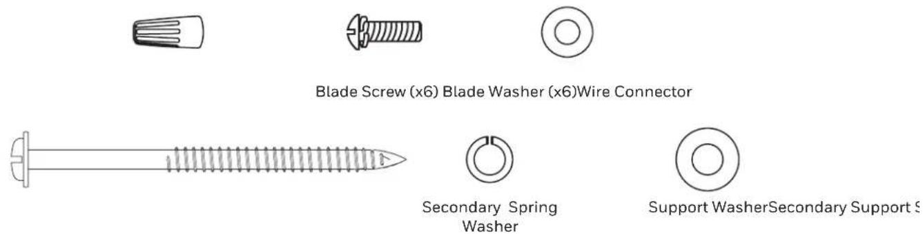
Turn off power to the fan at the breaker box and the wall switch (Figure 1.1). DANGER: Failure to disconnect the power supply prior to installation may result in serious injury or death.
-
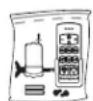
Choose one of the following mounting options (Figure 1.2):
Standard Mount - best suited for ceilings 8 feet or higher. For very high ceilings, use a longer downrod (not included).
Angle Mount - best suited for angled or vaulted ceilings. A longer downrod is sometimes necessary to ensure proper blade clearance. Ensure the ceiling angle is not steeper than 10 degrees.
Flushmount Installation - not available for this model.
Closemount Installation - not available for this model.
- Ensure the blades will be at least 30 inches from any obstructions. Also check the downrod length to ensure the blades will be at least 7 feet above the floor (Figure 1.3).
Figure 1.1
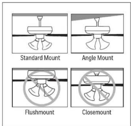
Figure 1.2
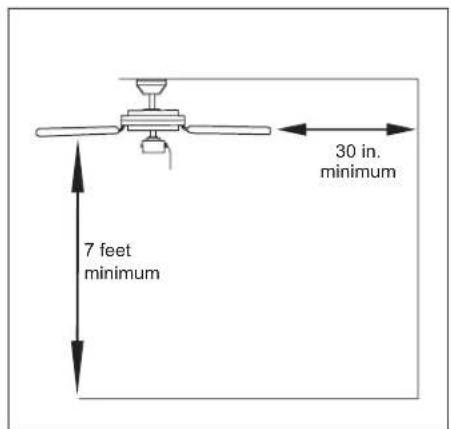
Figure 1.3
INITIAL INSTALLATION
- Firmly hold canopy while twisting the mounting bracket counterclockwise to remove (Figure 2.1).
- Install the mounting bracket to the outlet box (not included) using the screws and washers provided with the outlet box.
WARNING: To reduce the risk of fire, electric shock, or personal injury, mount to the outlet box marked "acceptable for fan support". (Figure 2.2).
- Remove and dispose of the orange packing material from the yoke of the motor assembly (Figure 2.3).
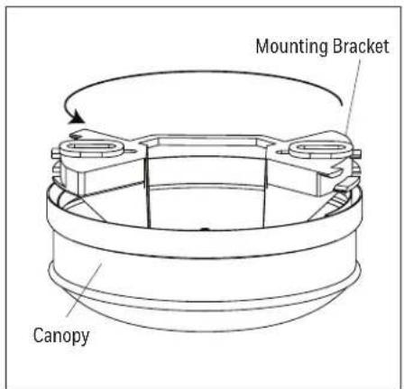
Figure 2.1
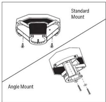
Figure 2.2
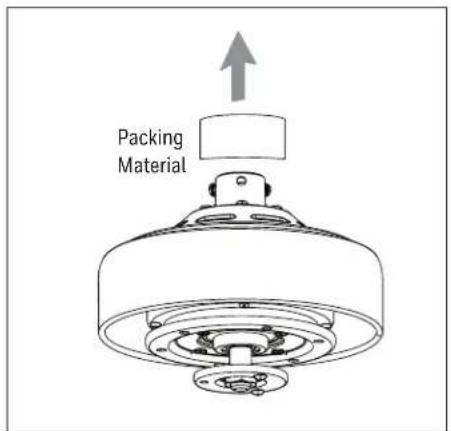
Figure 2.3
STANDARD OR ANGLE MOUNT INSTRUCTIONS
- Remove the downrod clip and downrod pin from the downrod. Then partially loosen the two set screws in the yoke at the top of the motor assembly (Figure 3.1).
- Insert the downrod through the canopy and yoke cover. Feed the wires and braided cable from the fan through the downrod and then through the downrod ball. Depending on the length of downrod you use, you may need to use the 36-inch lead wires to accommodate a 36 or 48-inch downrod (sold separately). When necessary, connect the 3-pin and 3-pin connector extending from the center of the downrod to one end of the 36-inch lead wires. Note: The downrod included with this fan will not utilize the 36-inch lead wires (Figure 3.2).
- Slide the downrod into the yoke of the motor assembly, align the holes, then re-install the downrod pin and downrod clip. Secure with the two set screws and slide the yoke cover down until it rests on top of the motor assembly (Figure 3.3).
- Install the ball end of the downrod into the opening of the mounting bracket. Rotate the downrod until the tab in the mounting bracket is seated in the slot in the downrod ball (Figure 3.4). WARNING: Failure to align the slot in the ball with the tap on the mounting bracket may cause the fan to fall, which could result in injury or death.
- Insert the receiver in the mounting bracket with antenna end first and flat side facing up. Note: The receiver rests directly on the downrod (Figure 3.5).
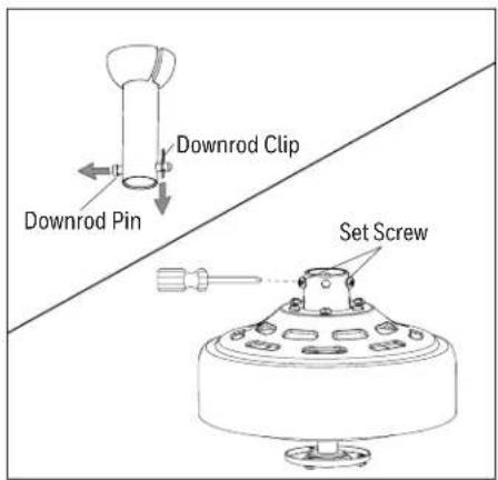
Figure 3.1
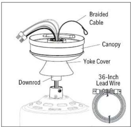
Figure 3.2 Figure 3.3
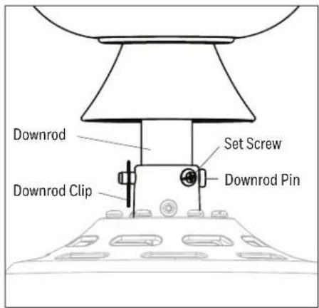
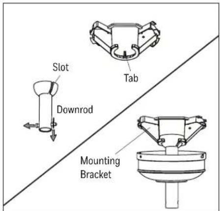
Figure 3.4
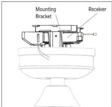
Figure 3.5
SECONDARY HANGING SYSTEM INSTRUCTIONS
For installation in the United States: Building codes in the U.S.A. do not require installation of a Secondary Hanging System. If desired, the braided cable can be cut and removed using wire cutters (sold separately). Skip to FINAL INSTALLATION. For installation in Canada: In compliance with building codes in Canada, installation of the Secondary Hanging System is required.
- WARNING: Secondary support is required for this product. Failure to follow the steps below could result in property damage and/or personal injury. Feed the loop of the braided cable, preassembled to the motor assembly, up through the outlet box mounted in the ceiling (Figure 4.1).
-
Install secondary support screw, spring washer and support washer partly into the side of the brace installed in the ceiling. Then loop the braided cable up and over the ceiling brace and place the open loop of the braided cable around the secondary support screw. Note: The ceiling support brace may not be accessible from below. If not, it must be accessed from above. Important: The braided cable must make a complete circle around the support brace to secure the fan (Figure 4.2).
-
Tighten the secondary support screw, securing the braided cable (Figure 4.3).
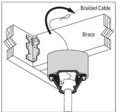
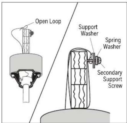
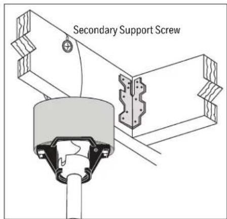
Figure 4.2 Figure 4.1 Figure 4.3
FINAL INSTALLATION
- Make the following wire connections according to the diagram and these steps (Figure 5.1):
- Use wire connector from hardware bag to connect the green wires from the downrod, mounting bracket, and receiver to the bare/green (ground) supply wire.
- Lift the lever and then push the White (neutral) supply wire into the empty hole of the wire connector preassembled to the white wire from receiver and then lower the lever to secure wire.
- Lift the lever and then push the Black (hot) supply wire into the empty hole of the wire connector preassembled to the black wire from the receiver and then lower the lever to secure wire.
- Connect the pin connectors on the wires from motor assembly to the connector ports in the receiver from remote pack. Important: If household supply wires are different colors than referred to above, a professional electrician should determine proper wiring.
- Lift the canopy over the mounting bracket and rotate clockwise until secure (Figure 5.2).
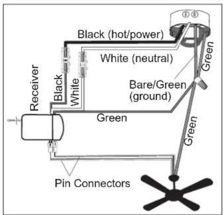
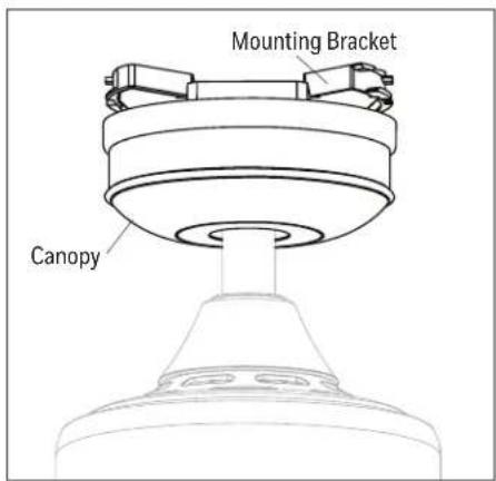
Figure 5.2 Figure 5.1
FINAL INSTALLATION
- Align the holes of one blade with two blade screw holes in underside of the motor assembly. Secure with the two blade screws and blade washers. Repeat this step for the remaining blades (Figure 5.3).
- Remove one of the three fitter plate screws preassembled to the fitter plate and loosen the other two but do not remove. Feed the 3-pin connectors through the center hole in the light pan. Align the keyhole slots in the light pan with the loosened screws in the fitter plate. Turn light pan clockwise and replace the previously removed fitter plate screw. Tighten all screws (Figure 5.4).
- Remove one of the three light pan screws from the light pan and loosen the other two but do not remove. Connect the 3-pin connector from the light pan to the 3-pin connector from the light kit. Lift the two keyhole slots in the light kit over the two loosened light pan screws and turn in a clockwise direction. Then, use the previously removed light pan screw to secure the light kit to the light pan. Tighten all screws (Figure 5.5).
- Attach the bowl to the light kit by twisting the bowl firmly in a clockwise direction until it is secure. CAUTION: Avoid cross-threading the bowl during installation. Improper installation could cause the bowl to be difficult to remove or fall, which could cause serious injury (Figure 5.6).
- Remote control comes equipped with a wall bracket. If you wish to install the wall bracket, remove the small plate to expose the screw holes. Insert wall brackets screws through holes and into wall, then cover with the previously removed small plate. The remote can be stored in the wall bracket for easy access (Figure 5.7).
- Turn on power to fan at breaker box and the wall switch (Figure 5.8). Assembly is complete.
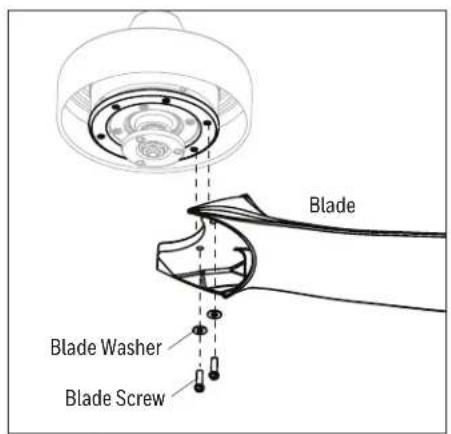
Figure 5.3
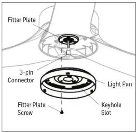
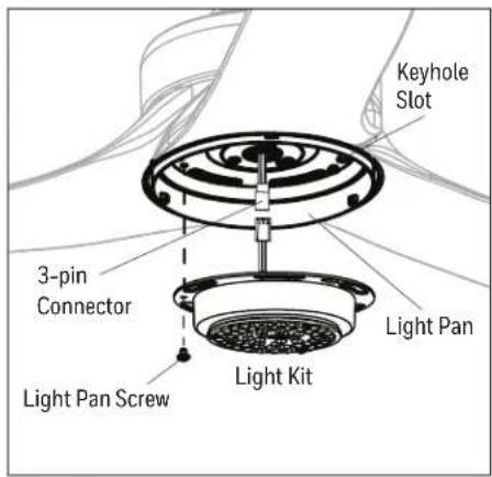
Figure 5.5 Figure 5.4
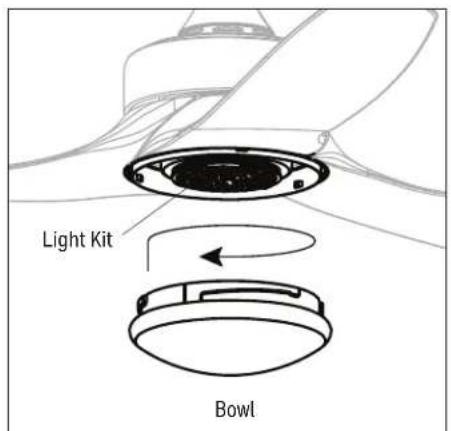
Figure 5.6
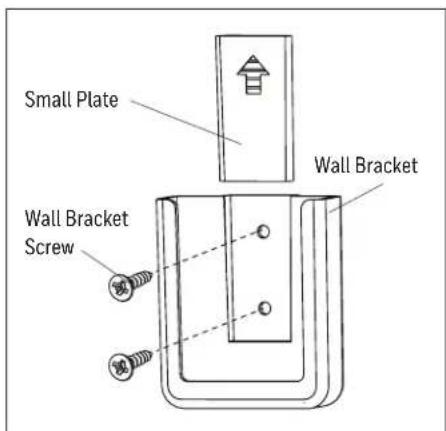
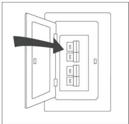
Figure 5.8 Figure 5.7
OPERATING INSTRUCTIONS
- Use a flat-head screwdriver, if necessary, to remove the battery cover from the back of the remote found in remote pack. Insert the battery into the remote; ensure polarity of battery matches the polarity indicated in the battery compartment -- positive (+) to positive (+) and negative (-) to negative (-). Replace the back cover and press the fan on/off button on the remote to ensure the LED indicator illuminates and the remote turns on the fan (Figure 6.1).
- To operate the fan using the remote, press and release the following buttons (Figure 6.2):
- LED Indicator - Indicates the six speeds of the fan. It should illuminate when any remote button is pressed. If not, replace the 1.5 V, AAA batteries.
- \* + Fan Power button has three options:
*/Turns the fan off or turns fan on at previously selected speed.
+ Increase fan speed
— Lower fan speed
2hr Sleep Timer - Turn off fan after 2 hours (2hr). Press Fan Power button to deactivate.
4hr Sleep Timer - Turn off fan after 4 hours (4hr). Press Fan Power button to deactivate.
8hr Sleep Timer - Turn off fan after 8 hours (8hr). Press Fan Power button to deactivate.
Reverse Switch - In warmer weather, push the reverse switch left, which will result in downward airflow creating a wind chill effect. In cooler weather, push the reverse switch right and the fan to low, which will result in upward airflow that can help move stagnant, hot air off the ceiling area. Important: Wait for the fan to stop before moving the reverse switch. The reverse switch must be set either completely left or right in order for the fan to function correctly. If the reverse switch is set in the middle position, the fan will not operate.
Light Delay - Delays turning off light for one minute which allows safe exit from room. Light blinks to confirm function is active. Press Light Control button to deactivate and turn the light off.
Home Shield™ - Simulates occupancy while away from home. Fan remains off and the light randomly turns on for a minimum of five minutes and a maximum of 20 minutes. The light remains off for 60 minutes between events. Press and hold button to activate. Light will blink to confirm Home Shield is active. Press any button to cancel.
Variable Breeze - Simulates a breeze in nature. Press and hold button to activate. Press any fan speed button to cancel.
Light Control - Tap button to turn the light off and on. Press and hold button to dim or brighten the lights.
Light Color - Press and hold button to cycle through the color temperatures from 2200K (warm white) to 6500K (daylight).
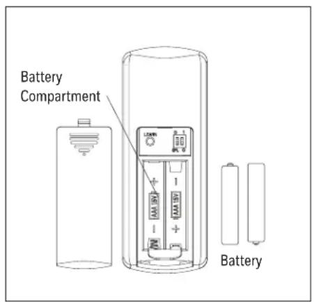
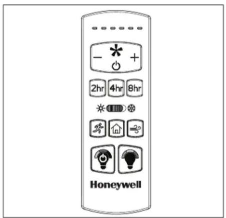
Figure 6.2 Figure 6.1
TROUBLESHOOTING
If you experience any faults, please check the Troubleshooting section below. If a problem cannot be remedied or you are experiencing difficulty in installation, please contact Customer Service: 1-877-361-3883, Monday-Friday, 8am - 5pm, Central Time.
WARNING: Shut off the power supply before you begin any maintenance task.
PROBLEM CORRECTIVE ACTION
| The fan does not move. | 1. Firmly push the reverse switch completely left or right.2. Make sure the wall switch is turned on.3. Turn the power on or check the fuse (breaker).4. Turn the power off and check all connections at the ceiling outlet box. |
| The fan is noisy. | 1. Check and tighten all screws that hold the fan blades to the motor.2. Replace the cracked blade.3. Do not use a full range dimmer switch to control the fan speed.4. Ensure the outlet box is secured to the building structure.5. Ensure the mounting bracket is secured to the outlet box and that the screws are tight. |
| The fan wobbles excessively. | 1. Check and tighten all screws that hold the fan blades to the motor.2. Switch one blade with a blade from the opposite side, or balance the fan using the blade balancing kit.3. Turn off the power. Loosen the canopy and verify that the mounting bracket is secure to the electrical outlet box. The bracket must be flush without movement against the outlet box. Verify the outlet box is secure.4. Use a longer downrod (sold separately) or move the fan to another location.5. Lift up the yoke cover and tighten the set screws on the yoke until secure. |
| The fan operates correctly but the lights are not working. | 1. Ensure the 3-pin connectors are properly secured.2. Turn the power off and check all connections at the ceiling outlet box. |
| Remote does not work. | 1. Power surge may have cleared the memory and remote needs to be resynced to the receiver.Syncing instructions:Turn off the power at the breaker box for at least 10 seconds and then turn the power back on. Within 30 seconds, press and hold the “LEARN” button (Figure 6.1) on the back of the remote for 3 seconds. The fan will turn on at high speed and light will blink twice and stay on, signaling a successful synchronization.2. Insert new AAA batteries in battery compartment of the wall control.3. If there are several remote fans in proximity, turn the power off to those fans and re-sync the fan. |
LIMITED LIFETIME WARRANTY
Set forth below, the manufacturer, Hong Kong China Electric Appliance Company (HKC) warrants the fan motor for this ceiling fan to be free from defects in workmanship and material for the life of the product. Also, subject to the limitations below, HKC warrants all ceiling fan parts (“ceiling fan parts” excludes the motor and parts made in whole or in part with glass) to be free from defects in workmanship and material for a period of one year after the date of purchase by the original purchaser at retail.
All claims must be made by the original purchaser, whether such purchaser purchased the product through a store or contractor. Ceiling fan part defects must be reported within the first year from the date of purchase. Parts made in whole or in part with glass and the finishes of metal and other surfaces are not warranted.
Purchasers are responsible for all costs of removing and reinstalling the product. Any damage to any part caused by ordinary wear and tear, accident, misuse, or improper installation, is not covered by this warranty. HKC assumes no responsibility whatsoever for fan installation. Any service performed by a non-licensed electrician will render the warranty invalid.
HKC's sole responsibility shall be to repair or replace the motor, parts, or product within the terms stated above. HKC shall not be liable for any loss or damage of any kind, including any incidental or consequential damages resulting directly or indirectly, from any breach of warranty, express or implied, or any other failure of this product. Some states do not allow the exclusion or limitation of incidental or consequential damages so this limitation may not apply to you.
If the original purchaser ceases to own the fan, this warranty is voided.
Should the purchaser encounter a problem with your fan related to defects in workmanship or materials within the warranty period associated with the defective part, HKC agrees to replace the defective part without charge, or at its option, to replace the ceiling fan with a comparable or superior model.
HKC's warranties are limited to the written warranties set out in this HKC ceiling fan limited lifetime warranty. All other express and implied warranties, including, without limitation, the implied warranty of fitness for a particular purpose and the implied warranty of merchantability are disclaimed. Some states do not allow the disclaimer of implied warranties, so this disclaimer may not apply to you.
REPLACEMENT PARTS LIST
For replacement parts, call our customer service department 1-877-361-3883, Monday-Friday, 8am - 5pm, Central Time.

DB

natural_image
Simple line drawing of a symmetrical mechanical or architectural component with curved ends and a central slot (no text or symbols)


53050
| A Light Kit | 4A000031240 |
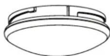
| B Bowl | 4A167620001 |
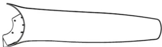
| C Blade (x3) | 4A086280005 |
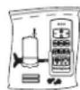
| D Remote Pack | 4A000031210 |
| HW Hardware Bag | 4A000031180 |
The Honeywell Trademark is used under license from Honeywell International Inc.
Honeywell International Inc. makes no representations or warranties with respect to this product.
This product is manufactured for Hong Kong China Electric Appliance, LTD. 3350 Players Club Parkway, Suite 225
Memphis, TN 38125
1 (877) 361-3883
10297·072225
EN | 11
Honeywell
Honeywell
natural_image
Line drawing of a three-blade propeller with a central hub and spout (no text or symbols)Modèle #53050
CONTENU DE L'EMBALLAGE
3350 Players Club Parkway #225
Memphis, TN 38125
1-877-361-3883
ENTRETIEN
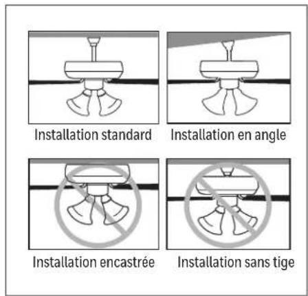
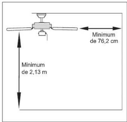
Figure 1.1 Figure 1.2 Figure 1.3
INSTALLATION INITIALE
Figure 2.1 Figure 2.2 Figure 2.3
INSTRUCTIONS POUR L'INSTALLATION STANDARD OU EN ANGLE
Figure 4.2 Figure 4.1 Figure 4.3
INSTALLATION DÉFINITIVE
Figure 5.5 Figure 5.4
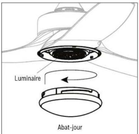
Figure 5.6
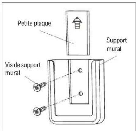
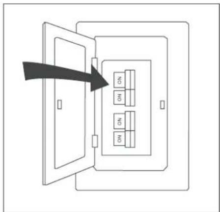
Figure 5.8 Figure 5.7
MODE D'EMPLOI
Figure 6.2 Figure 6.1
DÉPANNAGE
natural_image
Simple line drawing of a curved object with a circular cutout on the left side (no text or symbols)


53050
Hong Kong China Electric Appliance, LTD.
3350 Players Club Parkway, Suite 225
Memphis, TN 38125
1 (877) 361-3883
10297·072225
FR | 22
Honeywell
Honeywell
natural_image
Line drawing of a three-blade propeller with a central hub and spout (no text or symbols)Modelo #53050
3350 Players Club Parkway #225
Memphis, TN 38125
1-877-361-3883
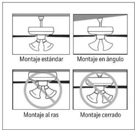
Figure 2.1 Figure 2.2 Figure 2.3
INSTRUCCIONES DE MONTAJE ESTÁNDAR O EN ÁNGULO
Figure 5.5 Figure 5.4
Figure 5.8 Figure 5.7
Figure 6.2 Figure 6.1
natural_image
Simple line drawing of a symmetrical object with a curved top and side profile (no text or symbols)O

O

HW
53050
| A Kit de illuminación | 4A000031240 |
| B Pantalla | 4A167620001 |
| C Aspa (x3) | 4A086280005 |
| D Paquete remoto | 4A000031210 |
| HW Bolsa de aditamentos | 4A000031180 |
Honeywell International Inc.
Honeywell International Inc. No representa o establece
Hong Kong China Electric Appliance, LTD.
3350 Players Club Parkway, Suite 225
Memphis, TN 38125
1 (877) 361-3883