
RVW417770 - Wine cellar GAGGENAU - Free user manual and instructions
Find the device manual for free RVW417770 GAGGENAU in PDF.


| Brand | Gaggenau |
| Model | RVW417770 |
| Product type | Built-in wine cellar |
| Dimensions (H x W x D) | 178 cm x 76 cm x 73 cm |
| Weight | 70 kg |
| Bottle capacity | 46 bottles (standard 0.75 L) |
| Temperature range | +5 °C to +20 °C |
| Number of temperature zones | 1 zone |
| Power supply | 220-240 V ~ 50 Hz |
| Annual energy consumption | 180 kWh |
| Climate class | SN-ST (from +10 °C to +38 °C) |
| Noise level | 38 dB(A) |
| Interior lighting | Warm white LED, dimmable |
| Controls | Electronic with digital display |
| Door type | Solid, reversible, with lock |
| Shelf material | Solid wood (beech) with telescopic slides |
| Special functions | Open door alarm, child lock, charcoal filter |
| Care and cleaning | Clean with a soft cloth and soapy water; do not use abrasive products |
| Spare parts and repairability | Parts available via Gaggenau after-sales service; repairable |
| Included accessories | Anti-tilt brackets, door key |
Frequently Asked Questions - RVW417770 GAGGENAU
User questions about RVW417770 GAGGENAU
0 question about this device. Answer the ones you know or ask your own.
Ask a new question about this device
Download the instructions for your Wine cellar in PDF format for free! Find your manual RVW417770 - GAGGENAU and take your electronic device back in hand. On this page are published all the documents necessary for the use of your device. RVW417770 by GAGGENAU.
USER MANUAL RVW417770 GAGGENAU
natural_image
Blue circular icon with a white human figure reading a book (no text or symbols)
en-us Installation Instructions

IMPORTANT SAFETY INSTRUCTIONS
READ AND SAVE THESE INSTRUCTIONS
Observe the following safety instructions.
WARNING
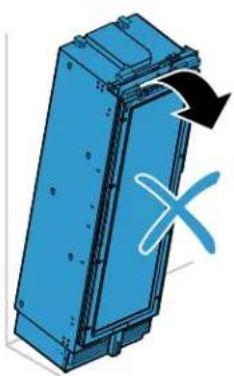
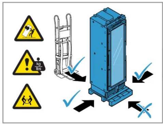
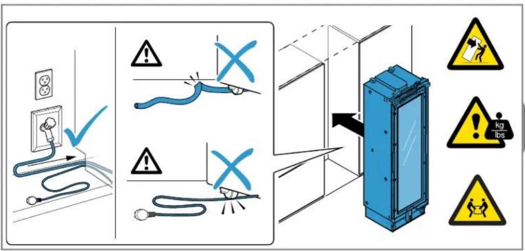
The appliance is very top-heavy and may tip over.
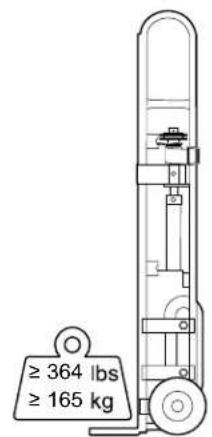
▶ The appliance must be transported by two or more people.
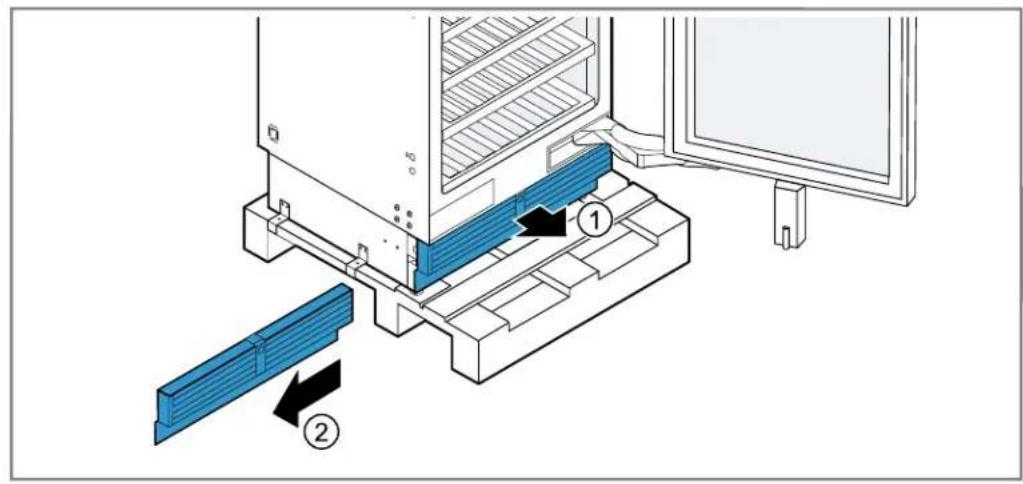
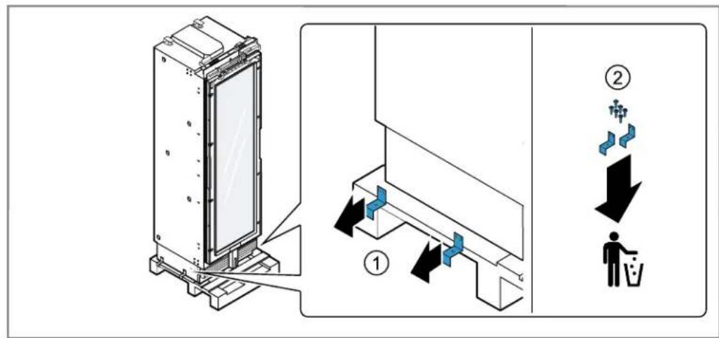
- Do not remove the appliance from the pallet until it is ready for installation.
- Keep the doors and drawers closed until the appliance is fully installed.
WARNING
The heavy weight of the appliance may result in injury when lifted.
▶ Do not lift the appliance on your own.
WARNING
Incorrect installation is dangerous.
▶ Never equip the appliance with an external switching device, e.g. a timer or remote control.
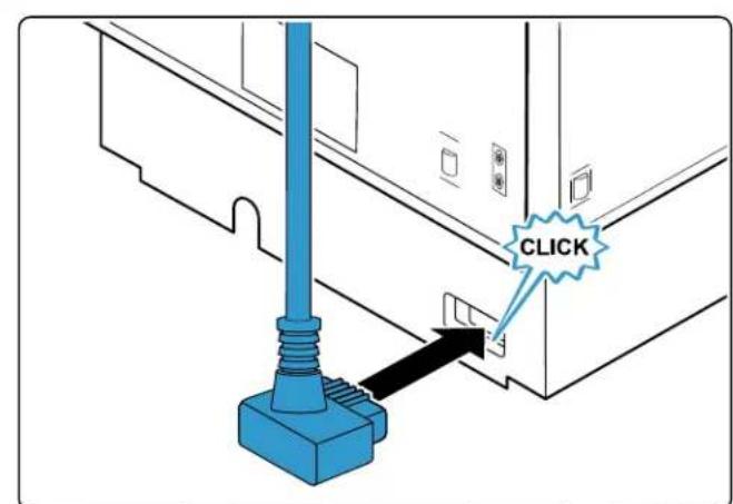
- When the appliance is installed, the mains plug of the power cord must be freely accessible. If free access is not possible, an isolating switch must be integrated into the permanent electrical installation according to the installation regulations.
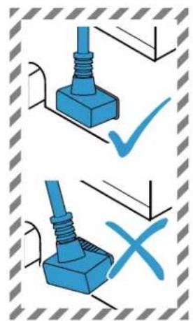
- When installing the appliance, check that the power cord is not trapped or damaged.
If the insulation of the power cord is damaged, that can be dangerous.
▶ Never let the power cord come into contact with heat sources.


IMPORTANT SAFETY INSTRUCTIONS
READ AND SAVE THESE INSTRUCTIONS
WARNING
If the appliance's ventilation openings are closed off, a leak in the refrigeration circuit may result in a flammable mixture of gas and air.
- Keep ventilation openings in the appliance casing or in the integrated casing clear of obstruction.
WARNING
It is dangerous to use an extended power cord and non-approved adapters.
- Do not use extension cords or multiple socket strips.
▶ Only use adapters and power cords approved by the manufacturer.
▶ If the power cord is too short and a longer one is not available, please contact an electrician to have the domestic installation adapted.
Portable multiple socket strips or portable power supply units may overheat and cause a fire.
- Do not place portable multiple socket strips or power supply units on the back of the appliance.
WARNING
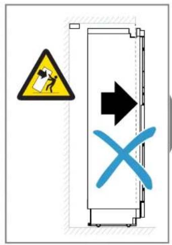
The appliance is very top-heavy and may tip over.
▶ The appliance must be installed by two or more people as soon as it is no longer secured and is removed from the pallet.
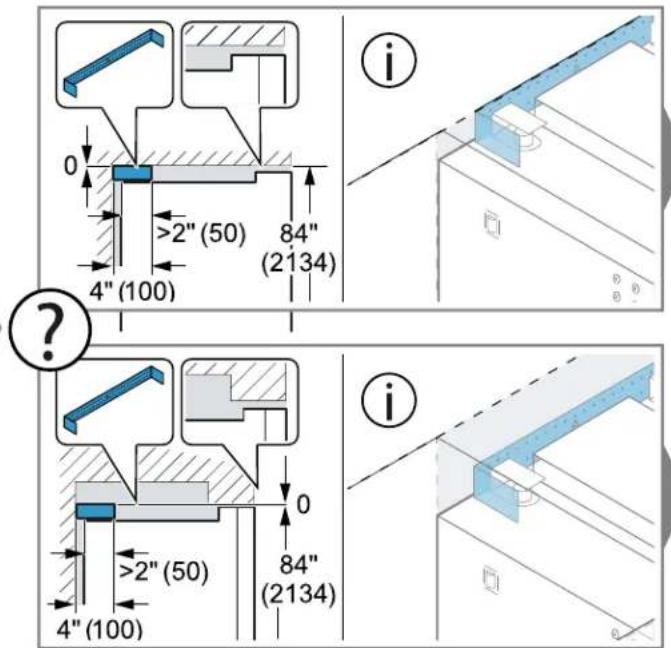
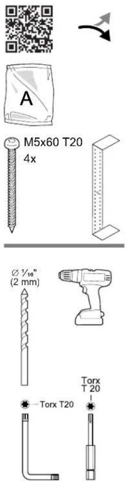
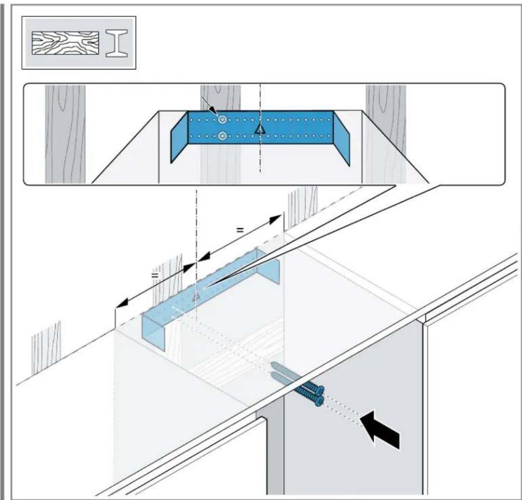
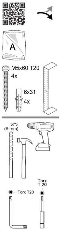
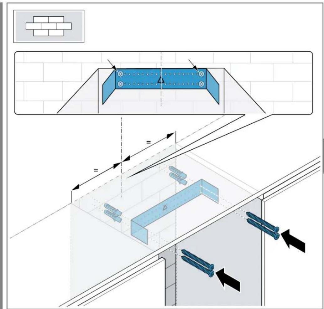
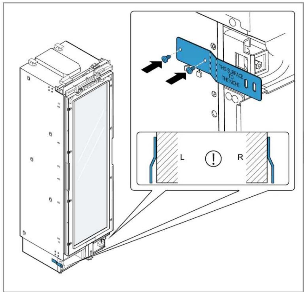
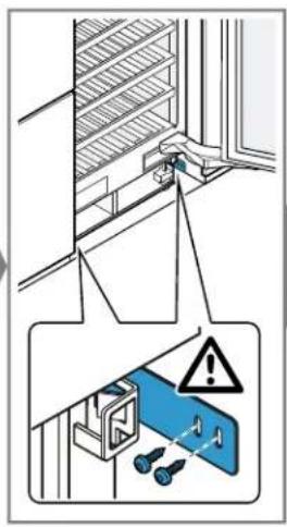
- Secure the unit using the supplied anti-tip bracket.
▶ Do not leave the appliance unattended during installation.


IMPORTANT SAFETY INSTRUCTIONS
READ AND SAVE THESE INSTRUCTIONS
CAUTION
Touching sharp edges on the appliance may lead to cuts.
▶ Wear protective gloves.
Preventing material damage
NOTICE:
The high weight of the appliance or, if not rolled in a straight line, the appliance's castors may damage the floor when the appliance is moved.
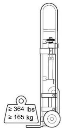
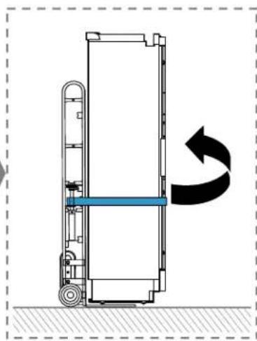
▶ Transport the appliance using a hand-cart.
▶ Use floor protection when moving the appliance, and do not move it in a zigzag fashion. Using the base, runners or appliance doors as a seat or climbing surface may damage the appliance.
Do not stand or lean on the base, runners or doors.


IMPORTANTES CONSIGNES DE SÉCURITÉ LIRE ET CONSERVER CES INSTRUCTIONS

IMPORTANTES CONSIGNES DE SÉCURITÉ
LIRE ET CONSERVER CES INSTRUCTIONS

IMPORTANTES CONSIGNES DE SÉCURITÉ LIRE ET CONSERVER CES INSTRUCTIONS
AVERTISSEMENT


natural_image
Shopping cart icon with a curved arrow indicating direction (no text or symbols)not supplied
non fourni
no suministrado
≤ 163 lbs (≤ 74 kg)

natural_image
Simple geometric diagram of a diagonal line within a dashed rectangle labeled T3 (no text or symbols beyond label)
≤ 156.5 lbs (≤ 71 kg)

natural_image
Simple geometric diagram of a diagonal line within a dashed rectangle labeled T3 (no text or symbols beyond label)
natural_image
Simple line drawing of a wrench and a curved arrow above it (no text or symbols)not supplied
non fourni
no suministrado


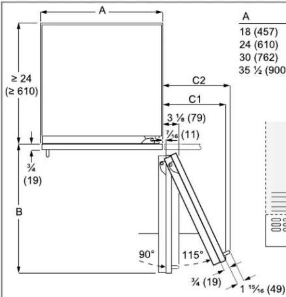
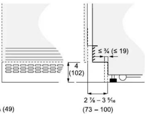
| A | B | C1 | C2 |
| 18 (457) | 20 3/3 (525) | 9 1/4 (235) | 10 7/16 (265) |
| 24 (610) | 26 % (677) | 11 3/4 (299) | 12 5/8 (330) |
| 30 (762) | 32 11/16 (830) | 14 5/16 (364) | 15 9/16 (395) |
| 35 1/2 (900) | 38 3/16 (970) | 16 1/2 (420) | 17 3/8 (442) |

natural_image
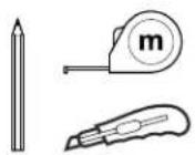
Pure technical diagram showing a vertical beam, a measuring tape, and a pencil (no text or symbols)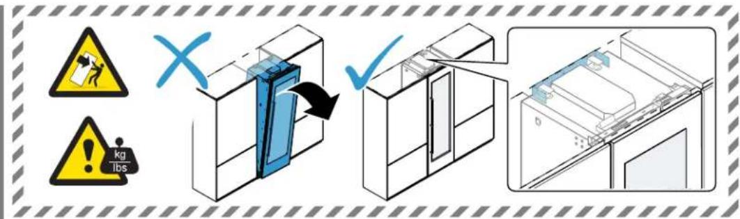

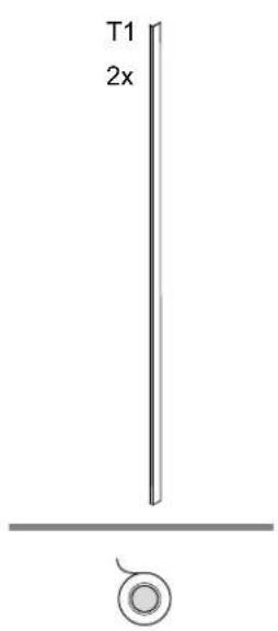
natural_image
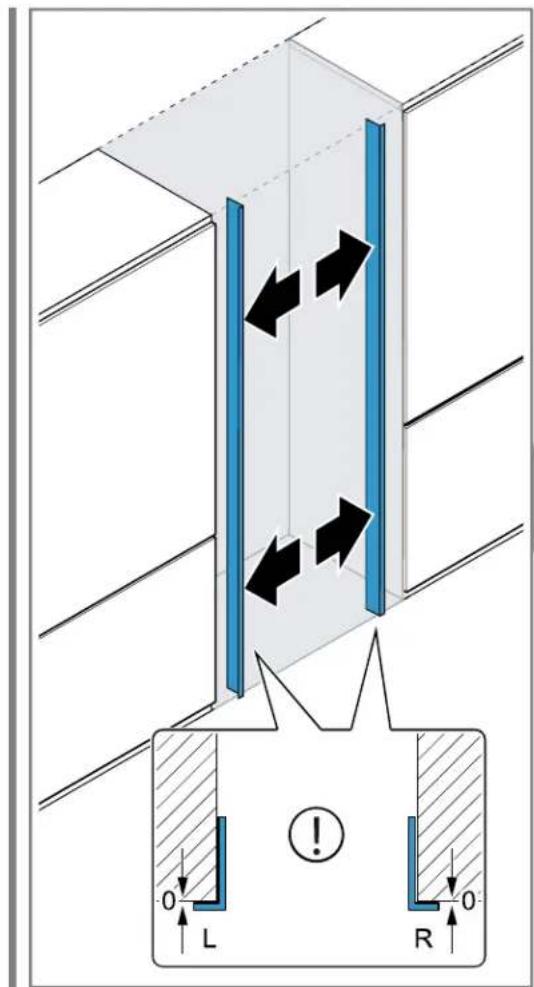
Architectural diagram showing structural components with blue vertical bars and gray beams, no text or symbols present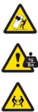
natural_image
3D diagram of a blue mechanical component with an arrow indicating rotation and a cross symbol (no text or labels)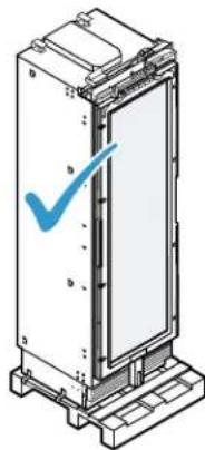
natural_image
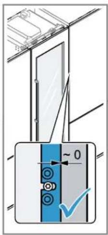
Technical line drawing of a vertical mechanical or electrical component with a blue checkmark indicating a detail (no text or symbols present)
natural_image
Diagram of a refrigerator with an open door and black arrow indicating rotation (no text or symbols)
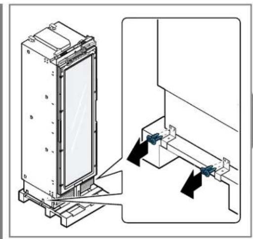
natural_image
Technical diagram showing a vertical panel mounted on a base with arrows indicating assembly or connection (no text or symbols present)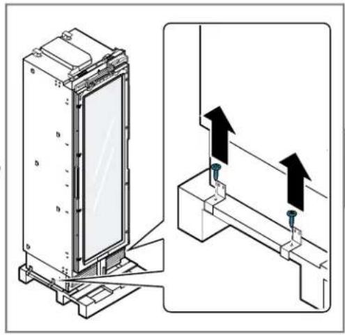
natural_image
Diagram of a vertical mechanical device with a blue horizontal bar and black curved arrow indicating rotation (no text or symbols)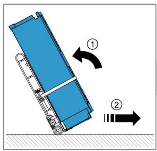
natural_image
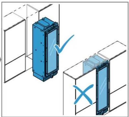
Isometric diagram of two blue rectangular panels inside a storage unit, with checkmark and cross symbols indicating inspection or validation (no text or labels present)
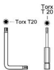
M4.2x6.5 T20

4x
natural_image
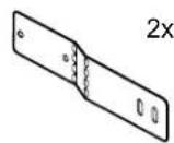
Technical line drawing of a vertical rectangular device with mounting holes and a diagonal line extending from its side (no text or symbols)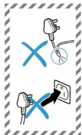


natural_image
Technical diagram showing a mechanical assembly with an inset view of a device mounted on a base (no text or symbols present)
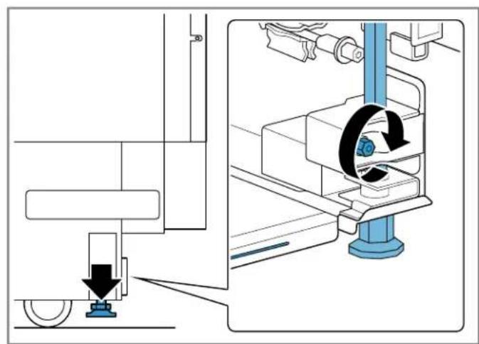
natural_image
Technical diagram showing a mechanical assembly with a blue tool and rotating component (no text or symbols)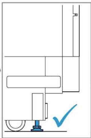
natural_image
Pure mechanical diagram showing a lever and shaft assembly without any text, numbers, or symbols
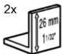
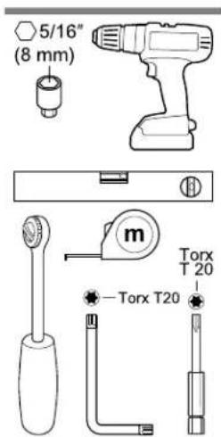
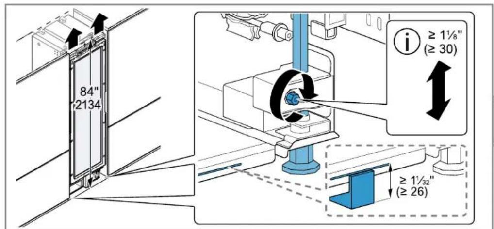
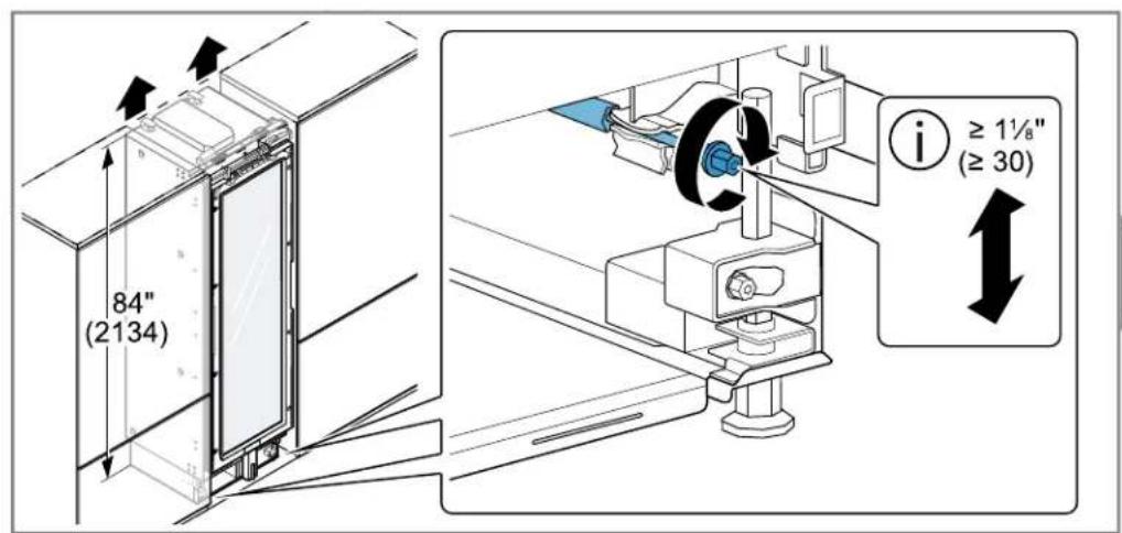
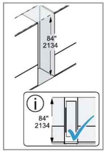
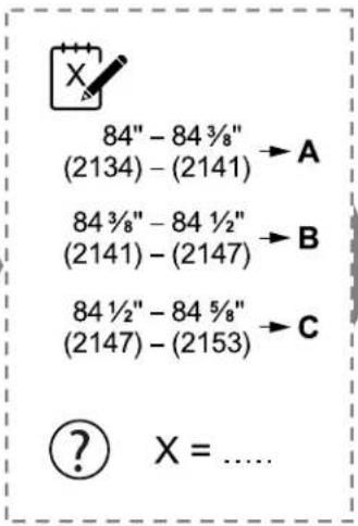
i
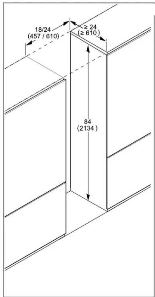
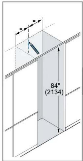
84"
(2134)
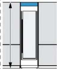
natural_image
Pure diagram of a vertical structure with horizontal arrows indicating depth or dimension (no text or symbols)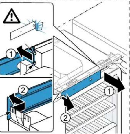
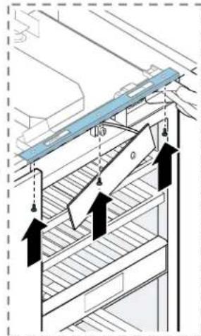
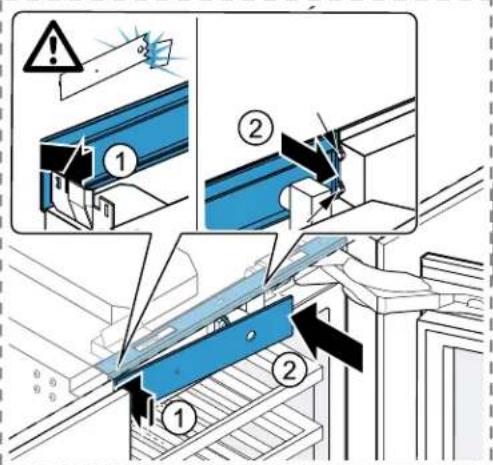
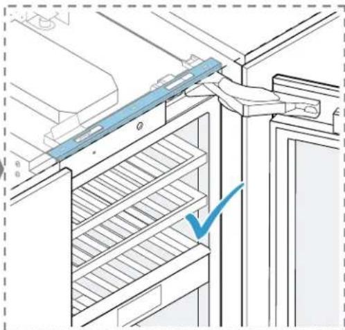
natural_image
Diagram of a refrigerator interior with a blue checkmark indicating a location or inspection (no text or symbols present)
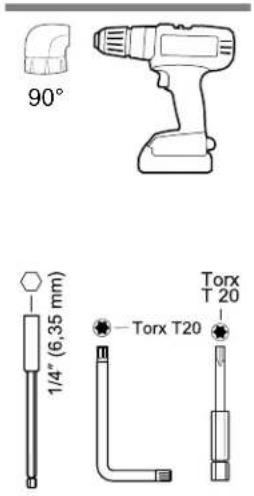
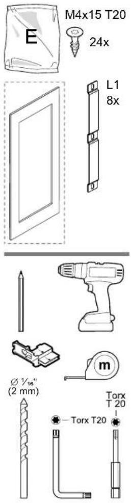
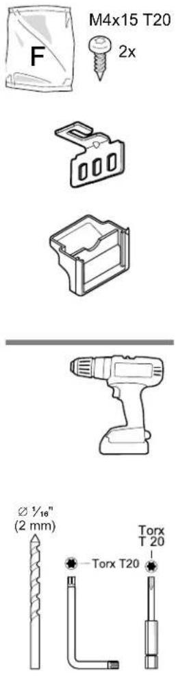
M4x15 T20

8x
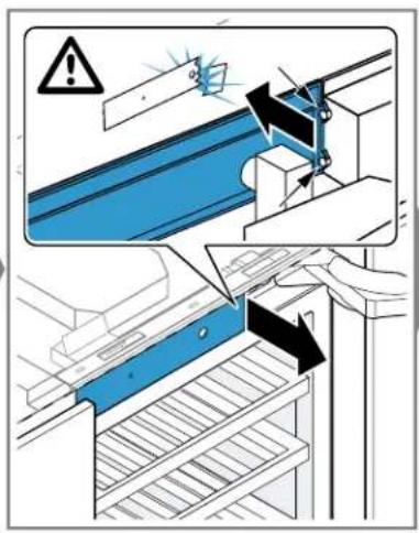

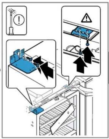
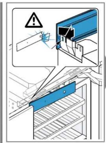
natural_image
Technical line drawing of a door frame assembly with mounting brackets and arrows indicating components (no text or symbols)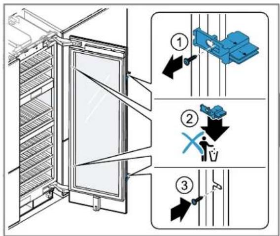
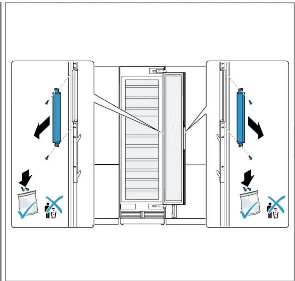
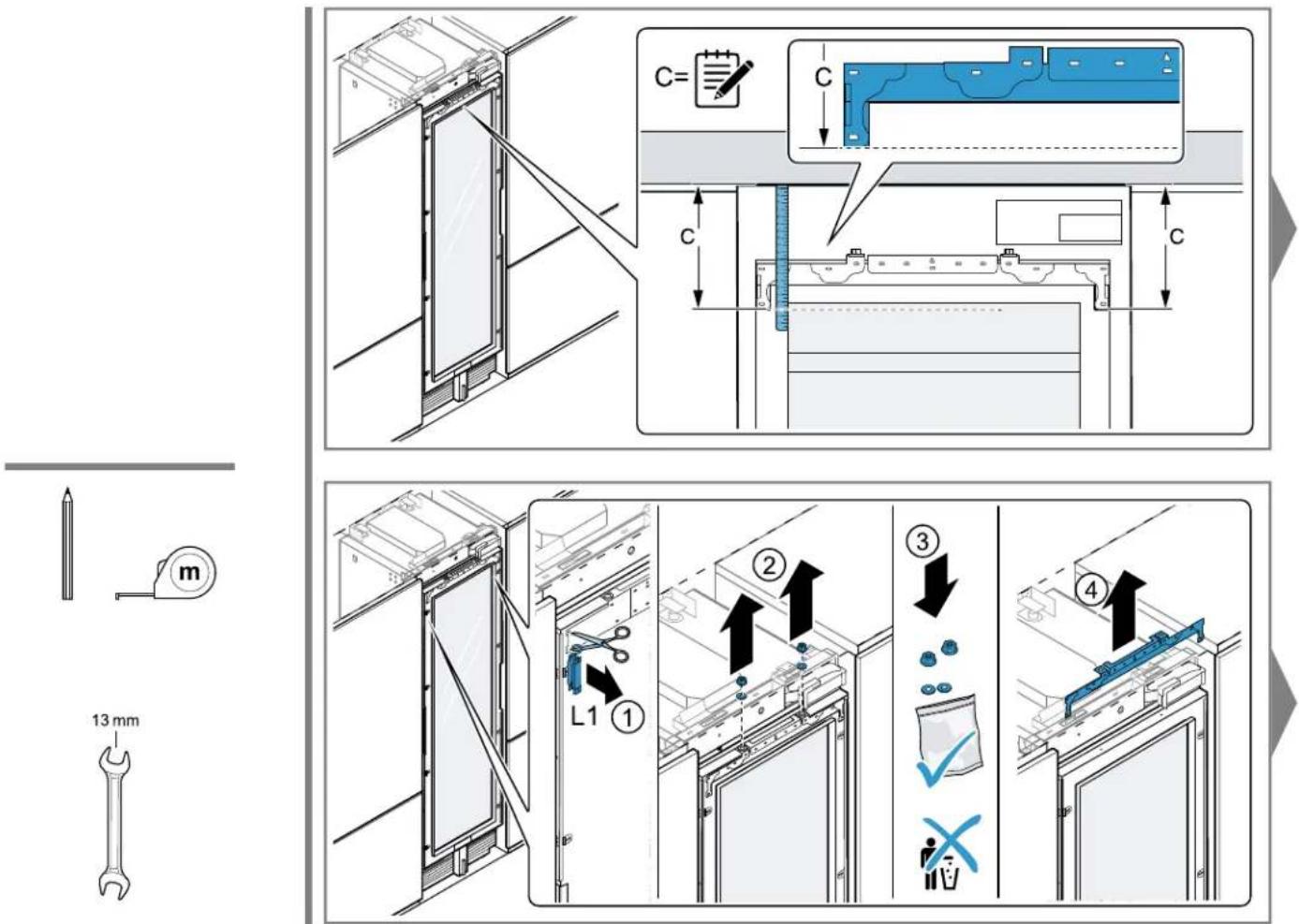
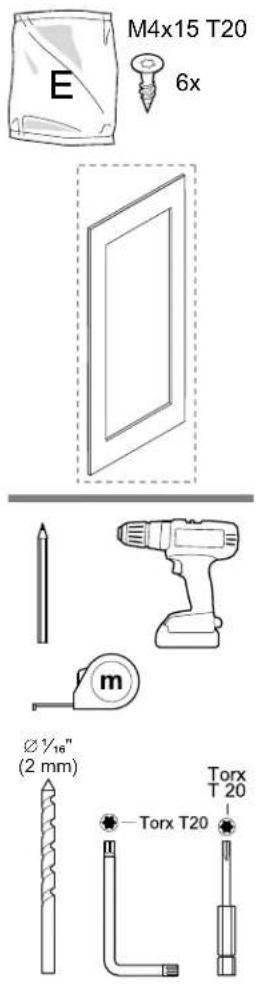

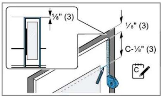
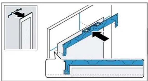
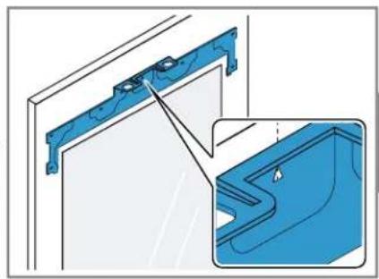
natural_image
Technical illustration of a blue mechanical bracket assembly with an inset close-up view (no text or symbols)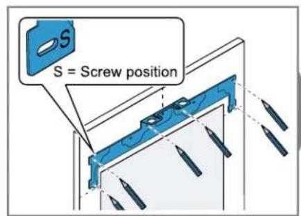
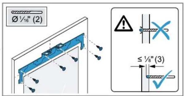
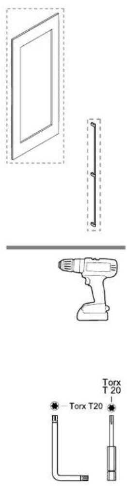

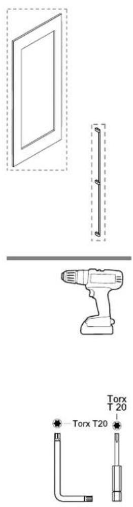
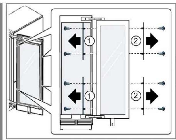
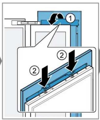
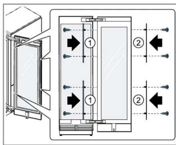
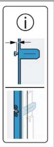
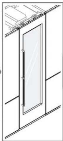
natural_image
Technical line drawing of a door frame with glass panel and window (no text or symbols)

natural_image
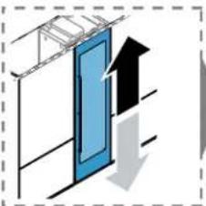
Diagram showing a blue panel with an upward arrow and a gray downward arrow, enclosed in a dashed border (no text or symbols)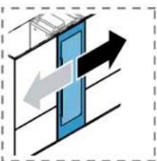
natural_image
Diagram showing two opposing arrows pointing left and right within a blue rectangular frame, enclosed in a dashed border (no text or symbols)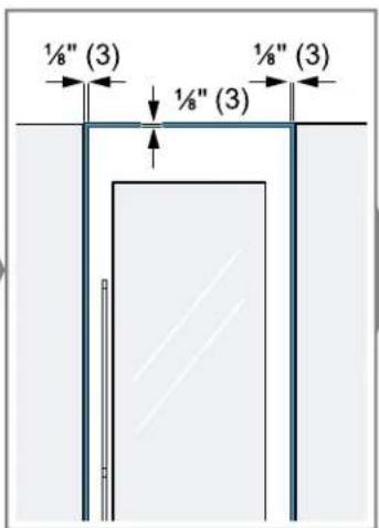
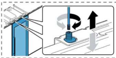
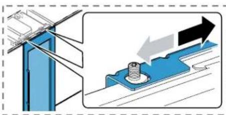
natural_image
Technical illustration showing a mechanical assembly with a blue frame and a bolted component, no text or symbols present.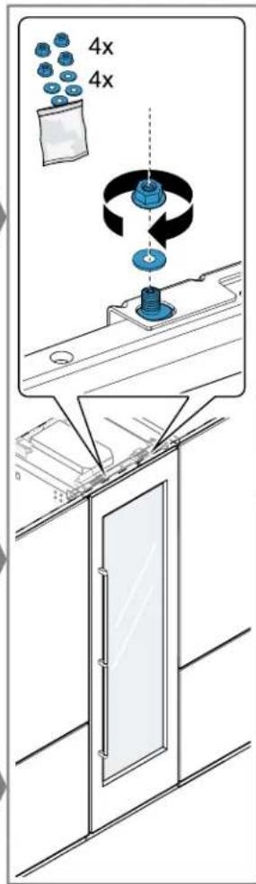
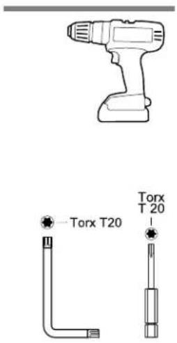
natural_image
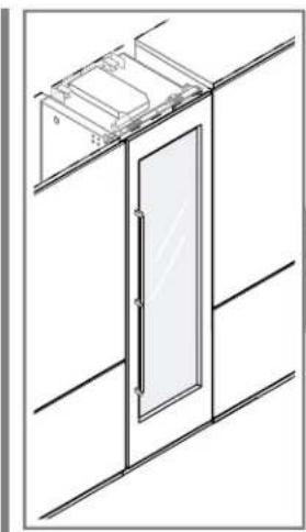
Technical line drawing of a door with an open lid and glass panel, mounted on a wall (no text or symbols)
natural_image
Diagram of a mechanical or fluidic system with directional arrows and a central blue component (no text or symbols)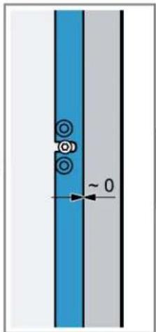
natural_image
Pure diagram of a vertical structure with blue and gray sections, showing circular features and a dimension arrow labeled '0' (no text or symbols beyond basic geometry)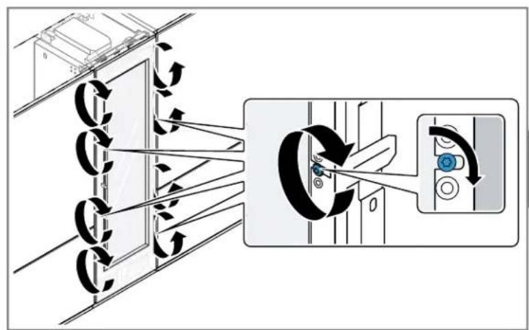
flowchart
graph TD
    A["Device Array"] --> B{Air Condition}
    B -->|Flow to| C["Control Loop"]
    C --> D["Device Placement"]
    D --> E["Return to Air"]
    style A fill:#f9f,stroke:#333
    style E fill:#bbf,stroke:#333
natural_image
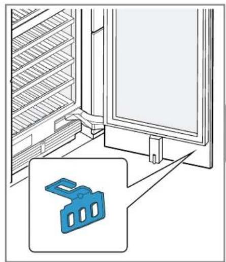
Interior view of a server room with rack-mounted shelves and a door, featuring a blue plastic component icon (no text or symbols)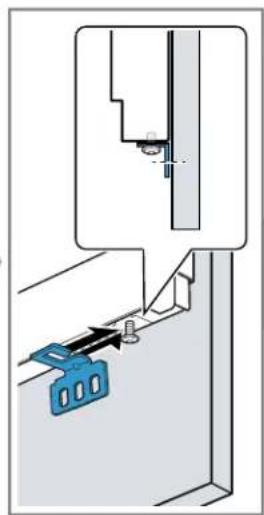
natural_image
Technical diagram showing a mechanical assembly with a blue tool and a bracket, no visible text or symbols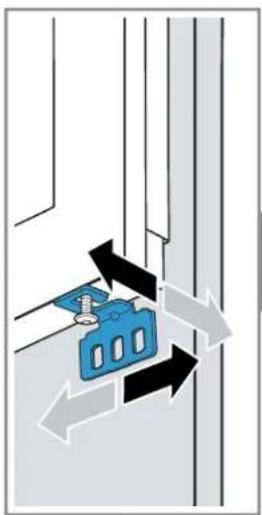
natural_image
Diagram showing a blue electrical switch mounted on a wall with directional arrows indicating motion (no text or symbols)
natural_image
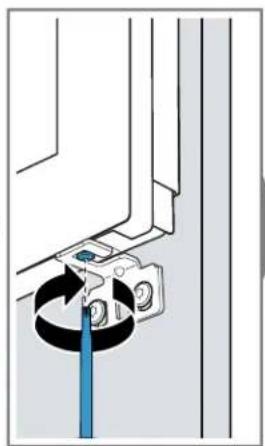
Diagram of a mechanical assembly with a blue tool inserted into a circular component (no text or symbols visible)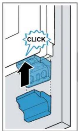
natural_image
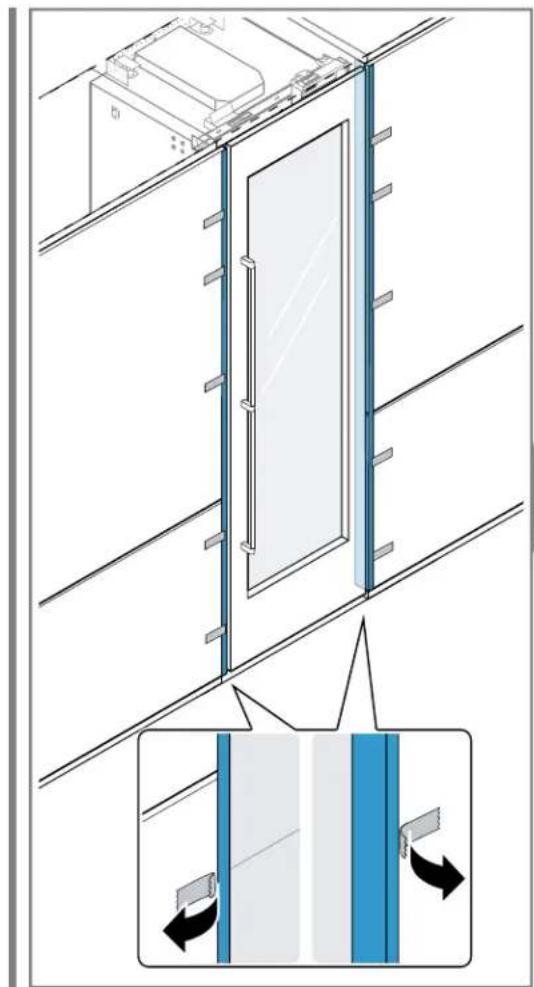
Diagram of a door assembly with directional arrows indicating movement, showing structural components and flow direction (no text or symbols)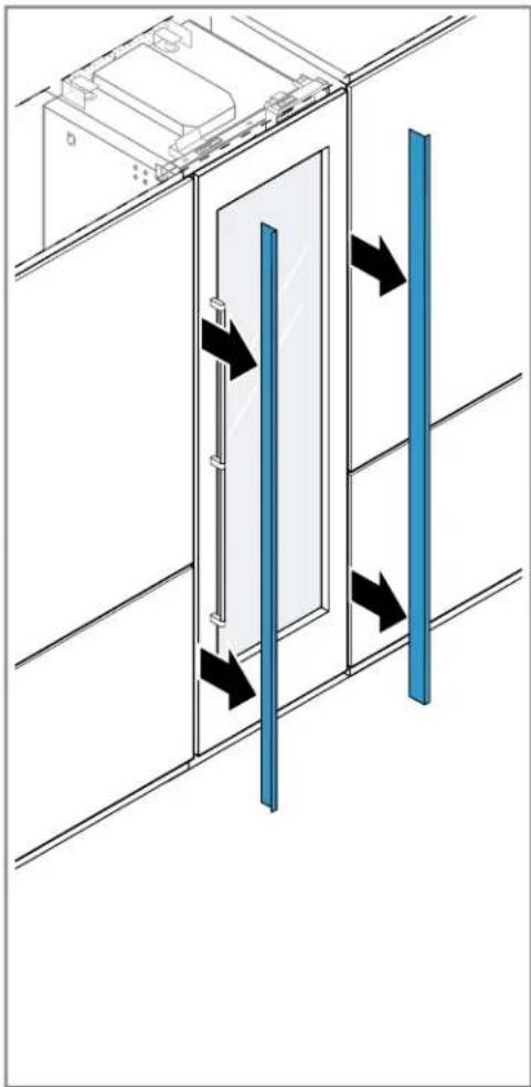
natural_image
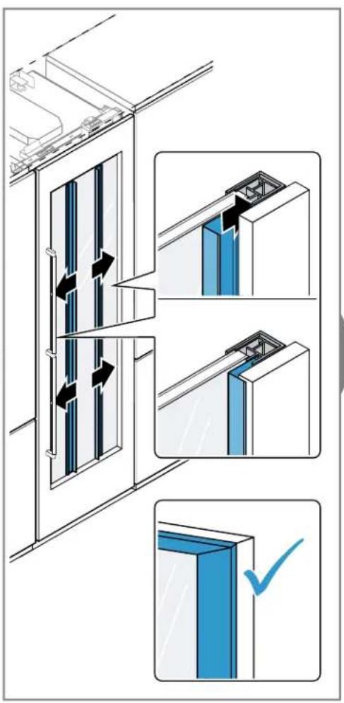
Diagram of a door with blue vertical bars and black arrows indicating movement or force, mounted on a wall (no text or symbols)
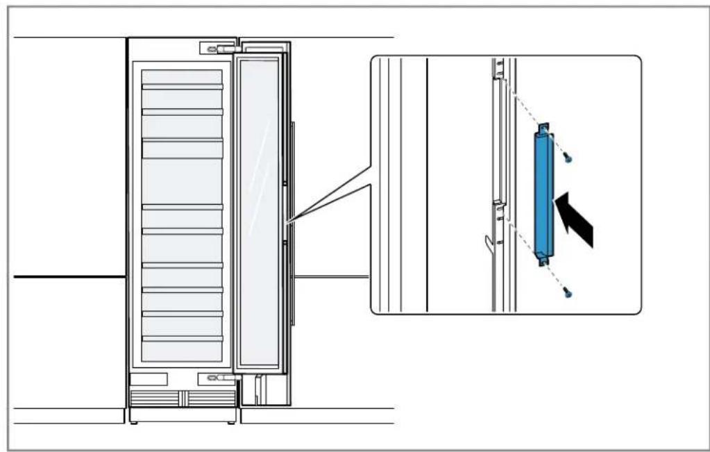
natural_image
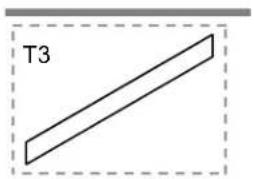
Simple geometric diagram showing a diagonal line inside a dashed rectangle labeled T3 (no text or symbols beyond label)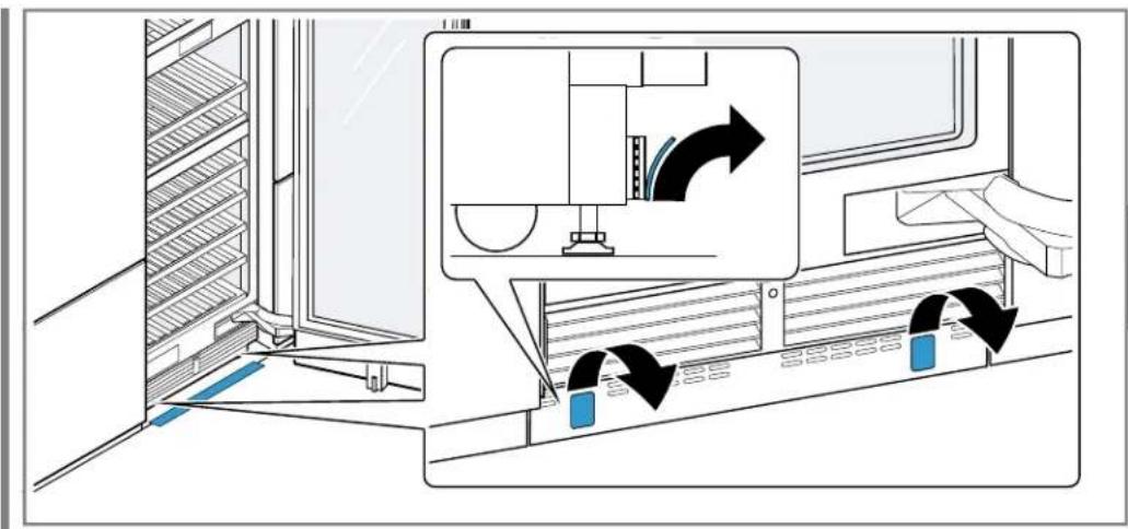
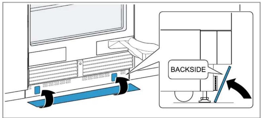
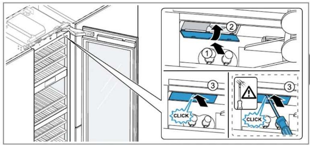
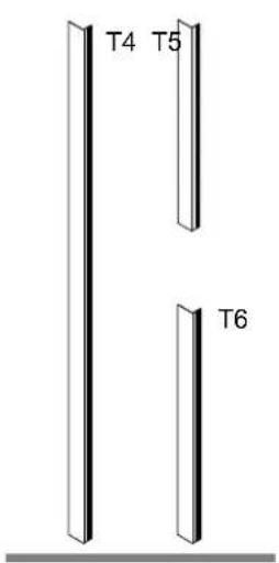
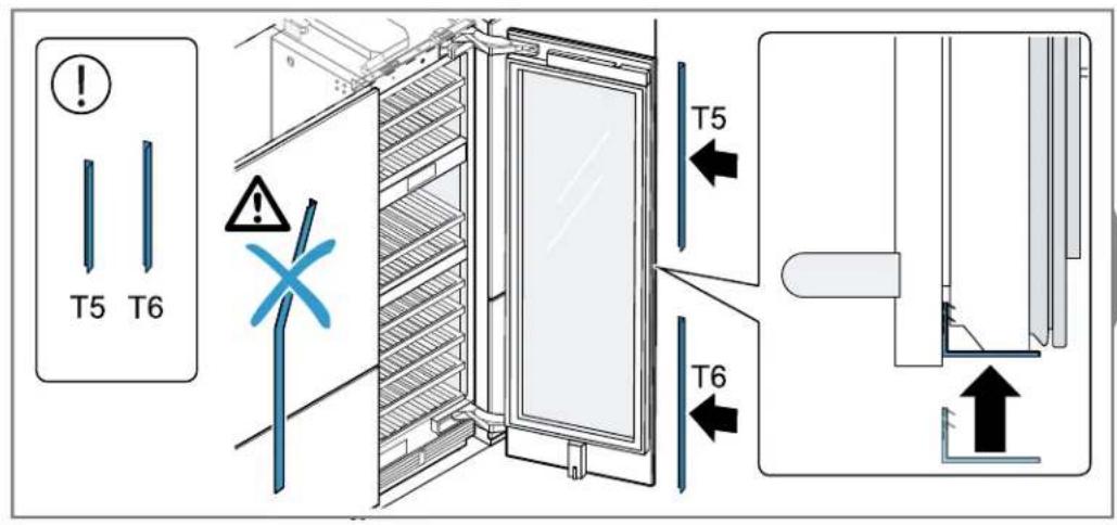
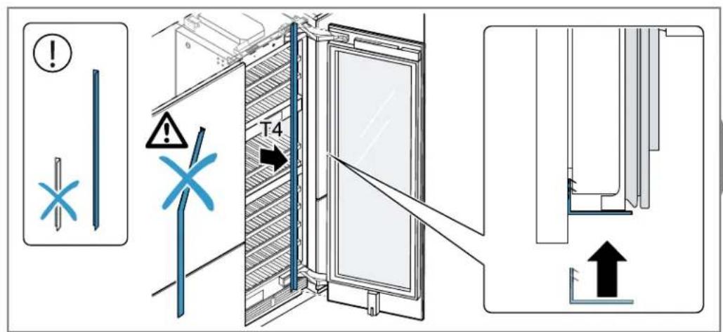
natural_image
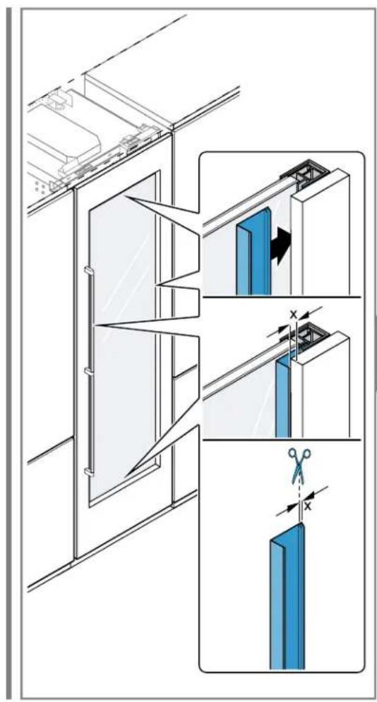
Technical diagram showing a door opening with blue insulation panels and a close-up of the interior panel (no text or symbols)
[FIGURE]

natural_image
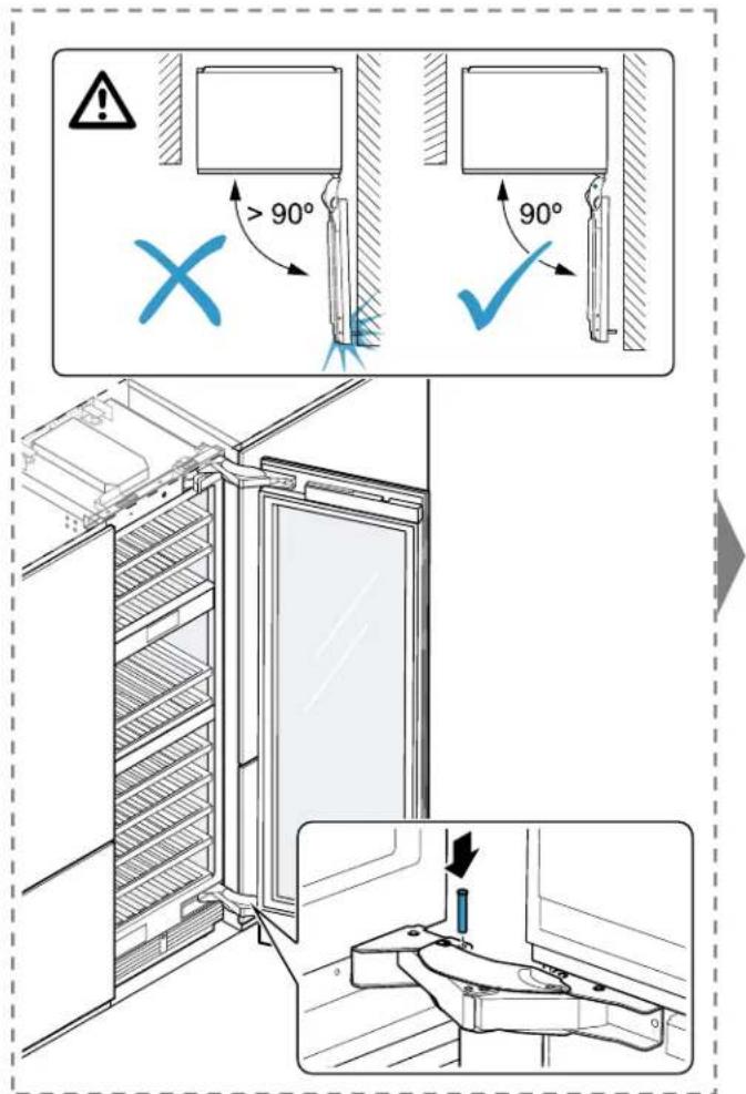
Technical line drawing of a door assembly with mounting bracket and safety checkmark (no text or symbols)
64

Brand : GAGGENAU
Model : RVW417770
Category : Wine cellar