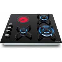
TGV4V-176 - Cooker Beldeko - Free user manual and instructions
Find the device manual for free TGV4V-176 Beldeko in PDF.


| Product type | Built-in mixed gas and ceramic hob |
| Brand | Beldeko |
| Model | TGV4V-176 |
| Cut-out dimensions (W x D) | 560 x 480 mm |
| Power supply | AC 220-240 V, 50/60 Hz |
| Total gas power | 6200 W |
| Total electric power | 1200 W |
| Auxiliary burner (gas) | 1.0 kW |
| Semi-rapid burner (gas) | 1.8 kW |
| Double crown wok burner (gas) | 3.4 kW |
| Ceramic hob Ø165 mm | 1.2 kW |
| Ignition | Integrated electronic |
| Safety device | Thermocouple (automatic gas shut-off if flame goes out) |
| Residual heat indicator | Yes |
| Surface material | Ceramic glass and stainless steel |
| Cleaning | Lukewarm water and non-corrosive detergent; scraper for encrusted residues |
| Safety instructions | Do not use steam cleaner, never leave unattended |
| Gas conversion | Possible (butane/propane to natural gas and vice versa) |
| Installation | Ventilation required, minimum distance of 420 mm from hood |
| Repairability | Spare parts available from manufacturer; after-sales service |
| Environmental information | Recycling via WEEE |
Frequently Asked Questions - TGV4V-176 Beldeko
User questions about TGV4V-176 Beldeko
0 question about this device. Answer the ones you know or ask your own.
Ask a new question about this device
Download the instructions for your Cooker in PDF format for free! Find your manual TGV4V-176 - Beldeko and take your electronic device back in hand. On this page are published all the documents necessary for the use of your device. TGV4V-176 by Beldeko.
USER MANUAL TGV4V-176 Beldeko
MANUEL D'UTILISATION
PLAQUE DE CUISSON À GAZ ET VITROCÉRAMIQUE ENCASTRABLE
RÉFÉRENCE : TGV4V-175 (PRG6040EG-A) TGV4V-176 (PRG6041EG-E)
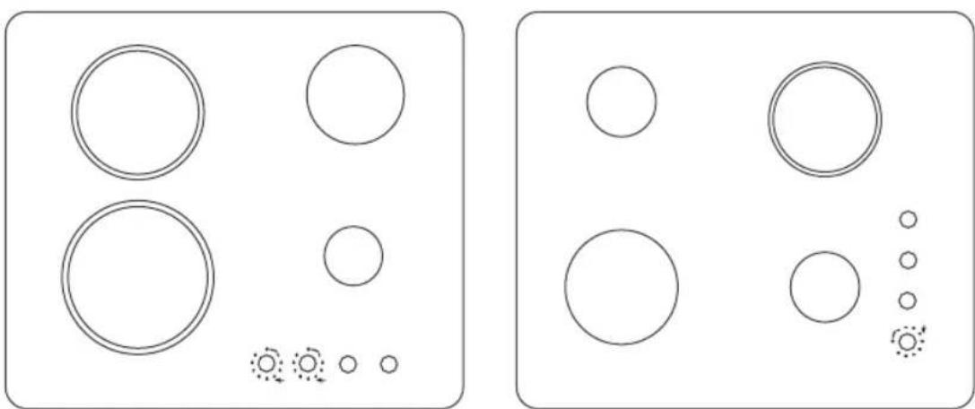
natural_image
Two identical diagrams showing circles arranged in rows and columns, with small circular elements and a few circled symbols (no text or labels)
natural_image
A plain white diagonal stripe on a white background, no text or symbols present.
natural_image
Pure white circular shape on white background with no text or symbolsBELDEKO


Chère Cliente,
Cher Client,
MERCI POUR VOTRE ACHAT
FÉLICITATIONS POUR VOTRE NOUVELLE TABLE DE CUISSON À GAZ ET INDUCTION ENCASTRABLE.
natural_image
Illustration of a hand using a brush to brush the material from a circular object (no text or symbols visible)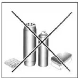
natural_image
Crossed black-and-white diagram showing three cylindrical objects and a rectangular object, no text or symbols present.Fig. 1 Fig. 2
natural_image
Simple line drawing of a house interior with a stove, roof, and air duct (no text or symbols)natural_image
Simple line drawing of a house with a stove and air duct (no text or symbols)natural_image
Technical line drawing of a door with a side-mounted device and a magnified inset showing internal components (no text or symbols)natural_image
Simple line drawing of a room with doors, a lamp, and a coffee cup (no text or symbols)text_image
700mm 400mm 800mm 400mm 150mm 3mm A Ø FO 0812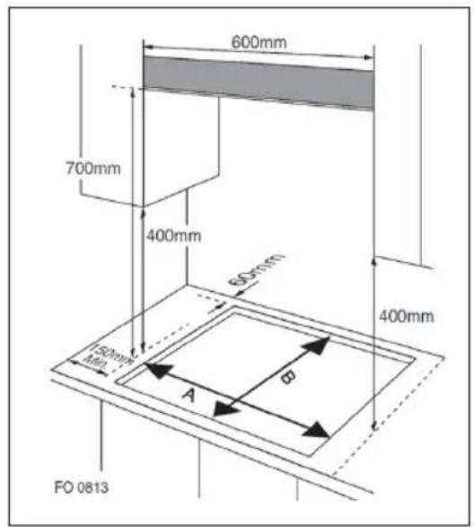
text_image
600mm 700mm 400mm 600mm 400mm 150mm Min A φ FO 0813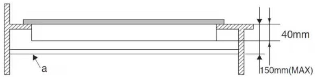
text_image
40mm 150mm(MAX) aFig. 6
natural_image
Technical line drawing of a mechanical component or assembly (no text or symbols visible)natural_image
Cross-sectional technical drawing of a mechanical assembly (no text or symbols visible)natural_image
Cross-sectional technical drawing of a mechanical assembly (no text or symbols visible)natural_image
Technical line drawing of a structural support frame with two horizontal bars and vertical supports (no text or symbols)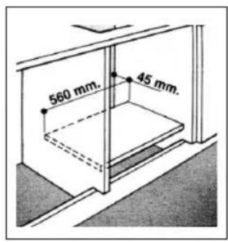
text_image
560 mm. 45 mm.natural_image
Simple line drawing of a circular mechanical component with an arrow pointing to its center (no text or symbols)REMPLACEMENT DE L'INJECTEUR DU BRÛLEUR
natural_image
Diagram of a mechanical assembly with a cylindrical component inserted into a base, showing no text or symbols.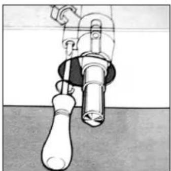
natural_image
Illustration of a mechanical valve or connector with a handle and shaft (no text or symbols)Fig.7
SÉLECTION DE LA FLAMME
We recommend that you spend some time to read this Instruction / Installation. Manual in order to fully understand how to install correctly and operate it. For installation, please read the installation section. Read all safety instructions carefully before use and keep this Instruction / Installation Manual for future reference.
1 - SAVE THESE INSTRUCTIONS
Risk of electric shock
- Disconnect the appliance from the power outlet before performing any work or maintenance.
- Connection to a proper grounding system is essential and mandatory.
- Any modification to the household wiring must be done by a qualified electrician.
- Failure to follow this advice may result in electric shock or death.
Risk reduction
- Be cautious – the edges of the panel are sharp.
- Lack of caution may cause injuries or cuts.
- Read these instructions carefully before installing or using this appliance.
- No combustible materials or products should ever be placed on this appliance.
- Provide this information to the person installing the appliance, as it may help reduce installation costs.
- To avoid any hazard, this appliance must be installed in accordance with the installation instructions.
- This appliance must be correctly installed and grounded by a qualified person.
- This appliance must be connected to a circuit that includes a breaker capable of fully cutting off the power supply.
- Improper installation may void any warranty or liability claims.
Risk of electric shock
- Do not cook on a broken or cracked cooktop. If the surface becomes broken or cracked, unplug the appliance immediately (from the wall switch) and contact a qualified technician.
- Unplug the cooktop before any cleaning or maintenance.
- Failure to follow this advice may result in electric shock or death.
Health risk
- This appliance complies with electromagnetic safety standards.

DANGER : Hot Surface s
- During use, accessible parts of this appliance will become hot enough to cause burns.
- Do not allow your body, clothing, or anything other than proper cookware to contact the induction glass surface until it has cooled.
- Metal objects like knives, forks, spoons, and lids should not be placed on the cooktop as they can become hot.
- Keep children away.
- Pan handles may be hot to the touch. Ensure handles do not extend over other active cooking zones and keep them out of children's reach.
- Failure to follow this advice can result in burns or scalds.
Risk reduction
- The blade of a cooktop scraper is exposed when the safety cover is retracted. Use with care and always store safely and out of reach of children.
- Lack of caution may result in injuries or cuts.
- Never leave the appliance unattended while in use. Boil-overs can cause smoke, and greasy residue may ignite.
- Never use your cooktop as a worktop or storage space.
- Never leave objects or utensils on the appliance.
- Never use the cooktop to heat or warm a room.
- After use, always turn off the cooking zones and the cooktop as described in this manual (i.e., using the control buttons).
- Do not let children play with or sit, stand, or climb on the appliance.
- Do not store items of interest to children in cabinets above the cooktop. Children climbing on the cooktop may be seriously injured.
- Do not leave children alone or unsupervised in the area where the appliance is in use.
- Children or people with disabilities that limit their ability to use the appliance must be accompanied and instructed by a responsible and competent person to use the appliance safely. The instructor must be confident that they can use it without danger to themselves or others.
- Do not attempt to repair or replace any part of the appliance unless specifically recommended in the manual. All other repairs must be done by a qualified technician.
-
Do not use a steam cleaner on your cooktop.
-
Do not place or move heavy objects on your cooktop.
- Do not stand on your cooktop.
- Do not use pots with rough edges or drag cookware across the induction glass surface as this can scratch it.
- Do not use abrasive cleaners or scouring pads, as they can scratch the glass surface.
- If the power cord is damaged, it must be replaced by the manufacturer, its service agent, or similarly qualified personnel to avoid danger.
- This appliance is intended for domestic use only.
WARNING : The appliance and its accessible parts become hot during use. Avoid touching heating elements.
- Children under 8 years old must be kept away unless continuously supervisede.
- This appliance can be used by children aged 8 and over and by persons with reduced physical, sensory, or mental capabilities, or lack of experience and knowledge, if supervised or instructed on safe usage and understanding of the risks.
- Children must not play with the appliance. Cleaning and maintenance must not be done by children without supervision.
WARNING : Unattended cooking with grease or oil can be dangerous and may cause fire. NEVER attempt to extinguish a fire with water. Instead, turn off the appliance and cover the flame with a lid or fire blanket.
WARNING : Fire hazard - do not store items on the cooktop.
WARNING : If the surface is cracked, turn off the appliance to avoid electric shock (applies to ceramic or similar glass surfaces that protect live components).
- Do not use a steam cleaner.
- This appliance is not designed to be operated by an external timer or separate remote control system.
WARNING : Cooking must be monitored. Short-term cooking must be continuously supervised.
WARNING : This cooktop must be installed stably to prevent tipping. Refer to the installation instructions.
WARNING : Use only the flame guards designed by the cooktop manufacturer or those specified as suitable in the user manual. Improper flame guards can cause accidents
This appliance must be grounded for user safety.
2 - CLOSE-UP VIEW
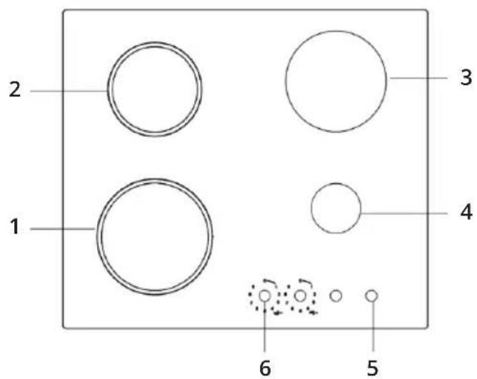
PRODUCT OVERVIEW 1 : TGV4V-175
text_image
1 2 3 4 5 6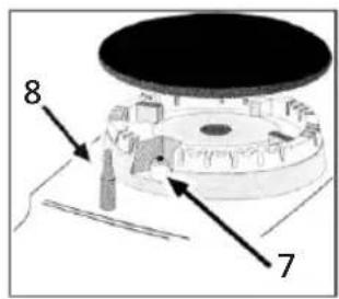
text_image
8 7- Semi-rapid burner : 1800 W
- Wok burner : 3400 W
- Ceramic burner : ∅ 165, 1200 W
- Ceramic burner : ∅ 200 mm, 1800 W
- Control knobs for ceramic burners
- Control knobs for gas burners
- Ignitor for gas burners (only on certain models)
- Safety device (only on certain models) - Activates if the flame accidentally goes out (spills, drafts, etc), interrupting the delivery of gas to the burner.
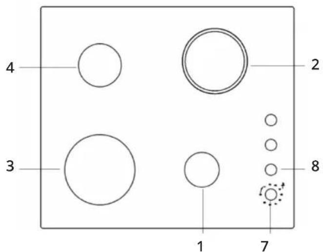
PRODUCT OVERVIEW 2 : TGV4V-176
text_image
4 3 1 2 8 7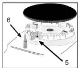
text_image
6 5- Auxiliary burner : 1000 W
- Ceramic burner : ∅ 165 mm, 1200 W
- Wok burner : 3400 W
- Semi-rapid burner : 1800 W
- Ignitor for gas burners (only on certain models)
- Safety device (only on certain models) - Activates if the flame accidentally goes out (spills, drafts, etc), interrupting the delivery of gas to the burner.
- Control knobs for ceramic burner
- Control knobs for gas burners
USE
3 - HOW TO USE THE APPLIANCE
The position of the corresponding gas burner is indicated on each control knob.
GAS BURNERS
• The burners are different in size and power.
- Choose the most appropriate one for the diameter of the cookware being used.
The burner can be regulated with the corresponding control knob by using one of the following settings :

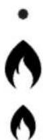
OFF HIGH LOW
ON THOSE MODELS FITTED WITH A SAFETY DEVICE
The knob must be pressed for about 6 seconds until the flame is lighted and warmed up.
ON THOSE MODELS FITTED WITH AN IGNITOR
The electric ignition button, identified by the ★ symbol, must be pressed first, then the corresponding knob is pushed and turned in the counter-clockwise direction to the «High" setting.
TO LIGHT A BURNER
Simply press the corresponding knob and turn it in the counter-clockwise direction to the High setting, keep press until the burner is lighted.
CAUTION
If the flame goes out accidentally, turn off the gas with the control knob and try to light it again at least 1 minute later.
TO TURN OFF A BURNER
Turn the knob in the clockwise direction until it is stopped (it should be on the « ● » setting).
flowchart
graph TD
    A["0"] --> B["1"]
    B --> C["2"]
    C --> D["3"]
    D --> E["4"]
    E --> F["5"]
    F --> G["6"]
    G --> H["7"]
    H --> I["8"]
    I --> J["9"]
CERAMIC BURNER
TO TURN ON THE CERAMIC BURNER
Turn the knob in the clockwise direction.
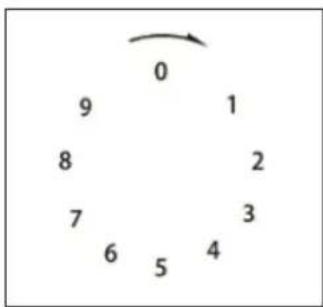
TO SELECT A HEATING LEVEL
The number around the outside of knob indicates the power level that you have set the zone. Each cooking zone can be adjusted between 1 and 9, one being the coolest zone setting and nine being the hottest zone setting.
TO TURN OFF A BURNER
Turn the knob in the anti-clockwise direction until it stops (it should be on the 0 position).
RESIDUAL HEAT INDICATOR
To the left of the control knob, there is one residual heat indicator.
TO CHOOSE THE RIGHT COOKWARE
Do not use cookware with jagged edges or a curved base.

Make sure that the base of your pan is smooth, sits flat against the glass, and is the same size as the cooking zone. Always centre your pan on the cooking zone.
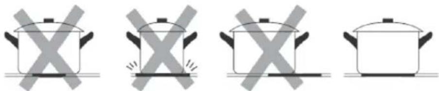
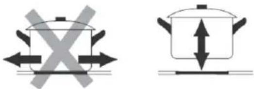
Always lift pans off the ceramic hob - do not slide, or they may scratch the glass.
CLEANING THE HOB
4 - CLEANING
Before cleaning or performing maintenance on your gas hob, disconnect it from the electrical power supply (included battery power). To extend the lifespan of the gas hob, it is absolutely indispensable that it is cleaned carefully, thoroughly and usually
Please keep in mind to the following :
- The enameled parts and the glass top, must be washed with warm water without using abrasive powders or corrosive substances which could ruin them.
- The removable parts of the burners should be washed usually with warm water and soap, make sure to remove caked-on substances.
• Automatic ignitor pin, the end must be cleaned carefully and usually, make sure ignition keep working normally.
- Stainless steel top plate and other steel parts can be stained if keep touch with high concentration calcareous water or corrosive detergents (containing phosphorus). To extend the lifespan, we advise these parts be rinsed thoroughly with water and dry them by blowing, It is a good idea to clean up any spills too.
• After glass hob working, the surface must be cleaned by a damp cloth to remove dust or food residues. Glass surface should be cleaned regularly with warm water and non-corrosive detergent.
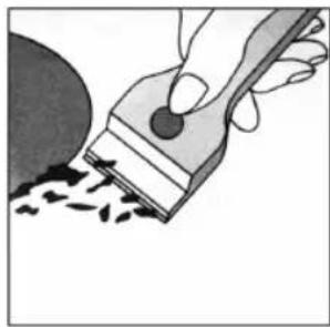
- First, to remove all food residues or greases with a cleaning scraper, e.g. Cleaning scraper (not supplied) (Fig. 1).
- While the cooking surface is warm, clean it with a suitable cleaning product and paper towels, then rub with a damp cloth and dry surface. Such as aluminum foil, plastic items, objects made of synthetic material, sugar or foods with a high sugar content that have been melted onto the surface, it must be removed immediately.
- While the cooking surface is still hot, clean it with a scraper and a transparent protective film which prevent to make more dirt. This also protect the surface from damage caused by food with a high sugar content.
- Do not use abrasive sponges or cleaning products, these holds true for chemically aggressive cleaners, like oven sprays and stain removers (Fig.2).
natural_image
Illustration of a hand using a brush to brush the material from a circular object (no text or symbols visible)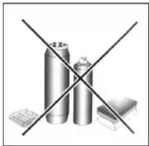
natural_image
Crossed black-and-white diagram showing three cylindrical objects and a rectangular block, no text or symbols present.Fig. 1 Fig. 2
- Cleaning the grill/pan support, it is recommended to clean it while it is still hot. To move grill away from the hob and put it in sink, remove the food residues or grease first, after grill has cooled, rinse it with water.
GREASING THE GAS VALVES
Over time, the gas valves may be sticked, and it is difficult to turn on/off. For this case, should clean the inside of valve and greased it.
→ Kind reminder : This procedure must be performed by a technician authorized by the manufacturer.
PRACTICAL ADVICE ON USING BURNERS
5 - PRACTICAL ADVICE
- Use the appropriate cookware for each burner (see table) in order to prevent the flame to reach the side of the pot or pan.
• Always use cookware with a flat bottom and keep the lid on.
- When the contents come to a boil, turn the knob to «Low».
| BURNER | ∅ COOKWARE DIAMETER(CM) |
| AUXILIARY BURNER | 10 - 14 |
| RAPID BURNER | 16 - 20 |
| WOK BURNER | 24 - 26 |
| CERAMIC BURNER∅ 165 MM | 16.5 |
| CERAMIC BURNER∅ 200 MM | 20 |
To identify the type of burner, refer to the designs in the section entitled, «Burner and Nozzle Specifications».
TROUBLESHOOTING
6 - TROUBLESHOOTING GUIDE
If you find the gas hob cannot work suddenly or cannot work properly. Before calling customer service for assistance, let us check what we can do. First of all, check and confirm there have no interruptions to the gas and electrical supplies, particularly, if the gas valves keeping turn on.
GAS BURNER
The burner cannot be lighted or the flame is not uniform around the burner :
- The gas holes on the burner are not clogged.
- All of the movable parts of burners are fixed correctly.
- There is no air flow around the cooking surface.
The flame does not keep lighting to the burner with thermocouple :
- You press the knob all the way.
- You keep pressing the knob for enough time to activate the thermocouple.
- The gas holes are not clogged in the area corresponding to the thermocouple.
The flame goes out while turning knob to « Low » setting :
• The gas holes are not clogged.
- There is no air flow around the cooking surface.
- The minimum has been adjusted correctly (see the section entitled « Minimum Regulation »).
The cookware is not stable :
- The bottom of the cookware is perfectly flat.
• The cookware is centered correctly on the burner. - The support grids have not been inverted.
CERAMIC BURNER
THE COOKING ZONES HAVE BECOME SOILED
This may be caused by burnt on remnants of food. This will not affect the working of the appliance. However, you should make sure that the cleaning instructions are being followed regularly.
THE RESIDUAL HEAT INDICATOR CANNOT WORK
If the cooking zone does appear to be hotter than 60 °C and the residual heat indicator has not come on, you should call the Service Department.
After checked all of these, the gas hob still does not work properly, please call the Customer Service Center and inform them of :
- Tile type of problem.
- The gas hob model number (Model....) as indicated on the packing carton.
→ Never call the technicians who is not authorized by your supplier, and refuse to use the spare parts which are not from manufacturer.
INSTALLATION
7 - INSTALLATION INSTRUCTIONS FOR THE HOB
The following instructions are directed at the qualified installer, so the installation and maintenance procedures may be followed in the most professional and expert manner.

IMPORTANT : UNPLUG THE ELECTRICAL CONNECTION BEFORE PERFORMING ANY MAINTENANCE OR REGULAR UPKEEP WORK.
→ The following requirements must be observed
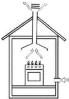
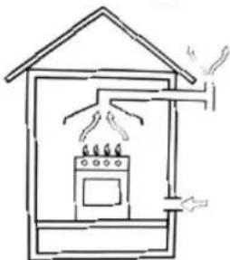
a) The room must be fitted with a ventilation system which ventilates smoke and gases from combustion to the outside of rooms. This must be done by hood or electric ventilator.
natural_image
Simple line drawing of a house interior with a stove, roof, and air conditioning unit (no text or symbols)Fig.1 Fig.2
In a chimney stack or branched flue. (exclusively for cooking appliances)
natural_image
Simple line drawing of a house with an oven and heating elements (no text or symbols)Directly to the Outside
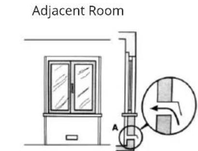
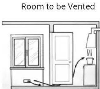
b) The room must be allowed for the influx of the air which is for proper combustion. The air flow for combustion purposes must not less than 2 m^3/h per kW of installed capacity. The air supply will be effected by influx from the outside through a duct, its inner cross section is at least 100 cm^2 and must not be blocked accidentally.
The gas hob without safety devices, to prevent flame go out accidentally, must have a ventilation working on twice volume. For example, a minimum of 200 ~cm^2 (Fig. 3). Otherwise, the room can be vented indirectly through adjacent rooms which is fitted with ventilation ducts to the outside. Although the adjacent rooms are not shared areas, bedrooms, but fire risk is hidden (Fig. 4).
text_image
Adjacent Room AExamples of ventilation holes for comburent air
text_image
Room to be VentedEnlarging the ventilation slot between window and floor
Fig. 4 Fig. 3
c) Intensive and prolonged working of the gas hob that needs to intensify ventilation, e.g. opening windows or increasing the power of the air intake system (if present).
d) Liquefied petroleum gases are heavier than air, so settle it downward. Rooms in which LPG tanks are installed must be fitted with ventilation to the outside to avoid of gas leakage. Therefore, LPG tanks which are empty or partially full, must not be installed or stored in rooms or spaces below ground level (cellars, etc). It is a good idea to keep only the tank which is working currently in the room, and make sure that it is not closed to heating source (ovens, fireplaces, stoves, etc).
INSTALLATION OF BUILT-IN GAS & CERAMIC HOB
The gas hobs are designed with protection degree against excessive heating, the appliance can be installed next to cabinets, and the height should not exceed the hob.
For a correct installation, the following precautions must be followed :
a) The hob may be located in a kitchen, a diner or bed/ sitting room, but not in a bathroom or shower room.
b) The furniture standing near to the unit, it is higher than the working boards, it must be placed at least 110mm distance to the edge of the board.
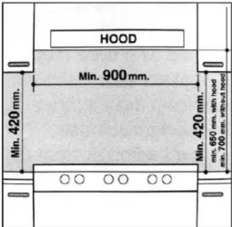
c) The cabinets should be positioned near to the hood at a height of 420 mm at least (Fig. 5).
text_image
HOOD Min. 900 mm. Min. 420 mm. Min. 420 mm. min. 650 mm. with hood min. 700 mm. without hoodFig. 5
d) Hob should be installed directly under a cupboard, the latter should be at least 700mm from the worktop, as shown in (Fig. 5).
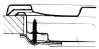
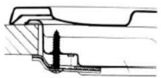
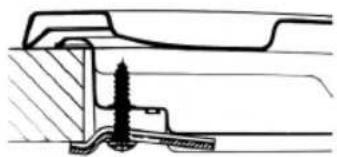
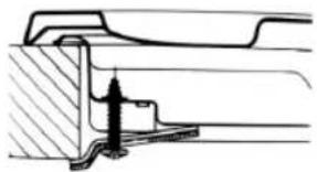
e) Fixing fittings (hooks, screws) are provided to place the hob on work top, measure 20 to 40 mm in thickness (see Fig. 6).
INSTALLATION SIZE
| MODEL A (MM) B (MM) | ||
| 60 CM 560 480 |
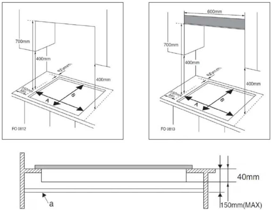
Fig.6
natural_image
Technical cross-sectional diagram of a mechanical assembly (no text or labels)Hook position for H = 20 mm top
natural_image
Technical line drawing of a mechanical assembly with no visible text or symbolsHook position for H = 30 mm top
natural_image
Technical cross-section diagram of a mechanical assembly (no text or labels)Hook position for H = 40 mm top
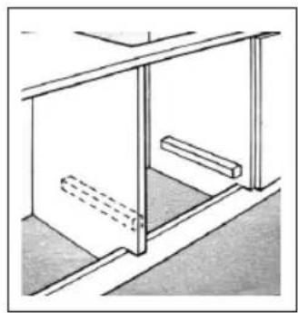
In the event the gas hob is not installed on a built-in oven, a wooden panel must be inserted for insulation. This panel must be placed at least 20 mm distance from the bottom of hob.
IMPORTANT: When installing the hob on a built-in oven, the oven should be placed on two wooden strips, in the case of a joining cabinet surface, remember to leave a space of 45 x 560 mm at least from the back side.
natural_image
Technical line drawing of a structural support frame with two horizontal bars and a dashed floor (no text or symbols)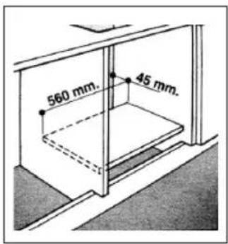
text_image
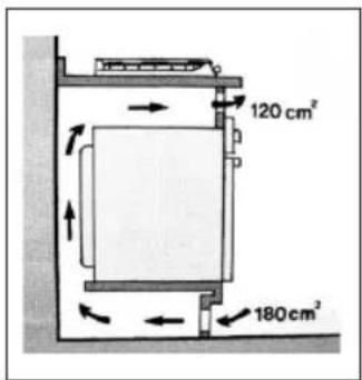
560 mm. 45 mm.When install hob on a built-in oven without forced ventilation, ensure that have air inlets and outlets to ventilate the interior of the cabinet adequately.
text_image
120 cm² 180 cm²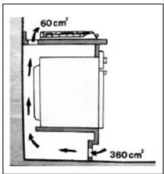
text_image
60 cm² 360 cm²HOB CONNECTION
- The gas hob should be connected to the gas-supply by a registered installer. During installation it is essential to fit an approved gas tap to isolate the supply from the hob for the convenience of any subsequent removal or servicing.
- Connect the hob to the gas mains or liquid gas, it must be carried out according to the prescribed regulation in force, and only after it is ascertained that it is adaptable to the type of gas to be used. If not, follow the instructions indicated in the paragraph headed « Adaptation to different gas types ».
- In the case of connection to liquid gas by tank, use pressure regulators that conform to the regulation in force.
IMPORTANT : For safety, for the correct regulation of gas use and long life of the hob, ensure that the gas pressure conforms to the indications given in table 1 « Burners and Nozzle Specifications ».
CONNECTION TO NON-FLEXIBLE TUBE (COPPER OR STEEL)
- Connection to the gas source must be done in such a way as to not create any stress points at any part of the gas hob.
- The hob is fitted with an adjustable « L » shape connector and a gasket to the gas supply.
- The connector should be dismounted and the gasket must be replaced. The feeding connector of the gas to the hob is threaded 1/2 gas cylinder.
CONNECTION TO FLEXIBLE STEEL TUBE
- The gas feed connector to the hob is threaded, 1/2» connector for round gas pipe. Only use pipes and sealing gaskets that conform to the standards currently in force. The maximum length of the flexible pipes must not exceed 2000 mm.
- Once the connection has been made, ensure that the flexible metal tube does not touch any moving parts and not be crushed.
CHECK THE SEAL
- Once the hob was installed, make sure all the connections are properly sealed, use a soapy water to test, never use flame.
ELECTRICAL CONNECTION
- The hob fitted with a tripolar electrical supply cord which are designed to be used alternating current. According to the indications on the rating plate located under the hob. The earthing wire can be identified by its yellow-green colour.
- In the case of installation over a built-in electric oven, the electrical connections for the hob and oven should be independent, not only for safe purpose, but also be convenient to remove them in the future.
ELECTRICAL CONNECTION FOR GAS HOB
- Fit the supply cord with a standard plug for the demand rate indicated on the rating plate or connect it directly to the electrical mains. In the latter case, a single pole switch must be placed between the hob and the mains, with a minimum opening between the contacts of 3mm in compliance with current safety codes (the earthing wire must not be interrupted by the switch).
- The power supply cord must be positioned so that it does not reach a temperature in excess of 50^ than room temperature at any point.
→ Before actual connection make sure that :
- The fuse and electrical system can withstand the load required by the hob.
- The electrical supply system is equipped with an efficient earth hook-up according to the norms and regulations prescribed by law.
- The plug or switch are easily accessible.
IMPORTANT : The wires in the main lead are coloured in accordance with the following code
As the colours of the wires in the main lead may not correspond with the coloured markings identifying the terminals in your plug, proceed as follows: Connect the Green & Yellow wire to terminal marked « E » or or coloured Green or Green & Yellow.
1/ Connect the Brown wire to the terminal marked «L» or coloured Red.
2/ Connect the Blue wire to the terminal marked «N» or coloured Black.
SPECIFIC TABLES
8 - BURNERS AND NOZZLE SPECIFICATIONS
Adapting the gas hob for different types of gas
| G30 | G20 (optional) | |||
| Burner | Thermal power (kW) | Nozzle 1/100 (mm) | Thermal power (kW) | Nozzle 1/100 (mm) |
| Auxiliary (small) (A) | 1.0 1.0 | 52 71 | ||
| Semi rapid (medium) | 1.8 1.80 | 67 97 | ||
| Rapid (R) | 2.40 2.40 | 77 110 | ||
| Triple ring (TR) | 3.40 3.40 | 93 125 | ||
| Supply pressures | 30 MBAR 20 MBAR | |||
At 15°C and 1013 mbar - dry ga
P.C.I.G20 37.78 MJ/m ^4
P.C.I.G25.1 32.51 MJ/m ^4
P.C.I.G25 32.49 MJ/m ^4
P.C.I.G27 30.98 MJ/m ^4
P.C.I.G2.350 27.20MJ/m ^4
P.C.I.G30 49.47MJ/Kg
natural_image
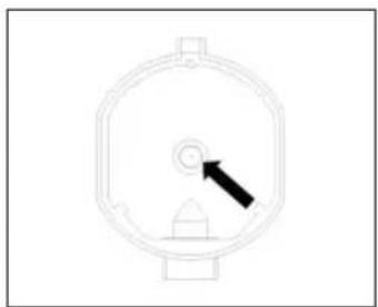
Simple line drawing of a circular mechanical component with an arrow pointing to its center (no text or symbols)REPLACEMENT OF BURNER NOZZLE
- Loosen the nozzle with a dedicated wrench (7).
- Fit the new nozzle according to the required gas type (see table 1 for reference).
→ After you have converted the gas hob to another gas type, make sure you have placed a label containing that information on the appliance.
9 - TABLE 2 : HOW TO CONVERT GAS SOURCE
Adjustment of the reduced valve flow
| Burners | Flame | Converting the hob from LPG to natural gas | Converting the hob from natural gas to LPG |
| Regular burners | Full flame | Replace the burner nozzle according to the guidelines in table 1 | Replace the burner nozzle according to the guidelines in table 1 |
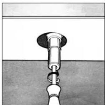
| Saving flame | Loosen the adjustment spindle (see fig.7 below) and adjust the flame | Loosen the adjustment spindle (see fig.7 below) and adjust the flame |
VALVE ADJUSTMENT
- Valve adjustment should be done with the control knob set at Burner ON saving flame position.
- Remove the knob, and adjust the flame with a tiny screwdriver (see fig.7 below).
natural_image
Diagram of a mechanical assembly with a cylindrical component inserted into a base, showing no text or symbols.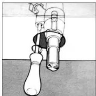
natural_image
Technical illustration of a mechanical component with no visible text or symbolsFig.7
To check the adjusted flame : heat the burner at full open position for 10 minutes. Then turn the knob into the saving setting. The flame should not extinguish nor move to the nozzle. If it extinguish or moves to the nozzle, readjust the valves.
FLAME SELECTION
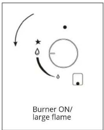
As the burners are adjusted correctly, the flame should be light blue, and the inner flame should be clear. The size of flame depends on the position of the related control knob.
Fig.8
text_image
Burner ON/ large flame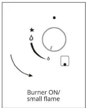
text_image
Burner ON/ small flame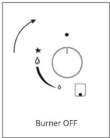
text_image
Burner OFFSee fig.8 for various operating options (flame size selection), the burner should be set at a large flame during the initial phase of cooking, it make food boil quickly. Then should turn knob to the saving flame position to maintain the cooking. It is possible to adjust the flame size stepless.
IT IS PROHIBITED TO ADJUST THE FLAME BETWEEN THE BURNER OFF AND BURNER ON LARGE FLAME POSITIONS
High quantity of energy can be conserved if the hob is used correctly, parameters are designed correctly, and appropriate cookware is used.
The energy conservation be as follows :
- Up to 60% are conserved when proper pots are used.
- Up to 60% are conserved when the unit is operated correctly and the suitable flame size is chosen.
It is a prerequisite for efficient and energy-saving operation of hob that the burners are kept clean at all times (in particular the flame slots and nozzles).
10 - TABLE 3 : ADAPTING TO DIFFERENT TYPES OF GAS
APPLIANCE CATEGORY : I2H I2E I2E+ I2L I2HS I2ELS I2ELW I3+ I3B/P I3B/P I3B/P I3P I2H3+ II2E3B/P II2HS3B/P II2ELWLS3B/P II2ELL3B/P
| Burner | Type of Gas | Pressure | Nozzle diameter | Nominal Charge | Reduced Charge | ||||
| mbar | 1/100mm | g/h | l/h | kW | kcal/h | kW | kcal/h | ||
| Auxiliary | Natural G20 | 20 | 71 | — | 95 | 1.0 | 860 | 0.40 | 344 |
| Butane G30 | 30 | 52 | 72.6 | — | 1.0 | 860 | 0.40 | 344 | |
| 37 | 47 | 72.6 | — | 1.0 | 860 | 0.40 | 344 | ||
| 50 | 45 | 72.6 | — | 1.0 | 860 | 0.40 | 344 | ||
| Semi-rapid | Natural G20 | 20 | 97 | — | 171 | 1.8 | 1548 | 0.60 | 516 |
| Butane G30 | 30 | 67 | 130.8 | — | 1.8 | 1548 | 0.60 | 516 | |
| 37 | 64 | 130.8 | — | 1.8 | 1548 | 0.60 | 516 | ||
| 50 | 59 | 130.8 | — | 1.8 | 1548 | 0.60 | 516 | ||
| Rapid | Natural G20 | 20 | 110 | — | 228 | 2.4 | 2064 | 0.90 | 774 |
| Butane G30 | 30 | 77 | 174 | — | 2.4 | 2064 | 0.90 | 774 | |
| 37 | 73 | 174 | — | 2.4 | 2064 | 0.90 | 774 | ||
| 50 | 67 | 174 | — | 2.4 | 2064 | 0.90 | 774 | ||
| Triple-ring wok | Natural G20 | 20 | 125 | — | 323 | 3.4 | 2924 | 1.50 | 1290 |
| Butane G30 | 30 | 93 | 247 | — | 3.4 | 2924 | 1.50 | 1290 | |
| 37 | 88 | 247 | — | 3.4 | 2924 | 1.50 | 1290 | ||
| 50 | 82 | 247 | — | 3.4 | 2924 | 1.50 | 1290 | ||
11 - TABLE 4 : GAS SOURCE AND NATIONAL COMPARISON TABLE
This hob conforms to the following European Economic Community directives :
- REGULATION(EU) 2016/426 (GAR)
- DIRECTIVE 2014/30/EU (EMC)
- DIRECTIVE 2014/35/EU (LVD)
| Gas group Supply pressure Country | ||
| I2H | G20 20mbar | AT, BG, CZ, DK, EE, FI, GR, HR, HU, IS, IE, IT, LV, LT, NO, PT, RO, SK, SI, ES, SE, CH, TR, GB |
| I2E | G20 20mbar | DE, LU |
| I2E+ | G20/G25 at 20/25 mbar | BE, FR |
| I2L | G25 25 mbar | NL |
| I2HS | G20/G25.1 25 mbar | HU |
| I2ELS | G20 20 mbar,G2.350 13 mbar | PL |
| I2ELW | G20/G27 20 mbar | PL |
| I3+ | G30-G31 (28-30)-37 mbar | BE, CY, CZ, EE, FR, GR, IE, IT, LT, LU, LV, PT, RO, SK, ES, CH, GB |
| I3B/P | G30 30 mbar | BE, CY, CZ, DK, EE, FI, GR, HR, LV, LT, LU, MT, NL, NO, SK, SI, SE, TR |
| I3B/P | G30 37 mbar | PL |
| I3B/P | G30 50 mbar | AT, DE, HU, CH |
| I3P | G31 37 mbar | CH,FR,GR,IE,ES,GB |
| I2H3+ | G20 20 mbarG30-G31(28-30)-37mbar | GR,IE,IT,PT,ES,GB,CH,CZ,SI,SK |
| II2E3B/P | G20 20 mbar, g30 30mbar | RO |
| II2HS3B/P | G20/G25.1 25mbar,G30 30mbar | HU |
| II2ELWLS3B/P | G20/G27 20mbar,G2.350 13mbar, G30 37mbar | PL |
| II2ELLL3B/P | G20 20mbar,G25 25mbar,G30 50mbar | DE |
12 - NOTICE
- Prior to installation, ensure that the local distribution condition (nature of the gas pressure) and the adjustment of the appliance are compatible.
- The adjustment conditions for this appliance are stated on the rating label.
- This gas hob is not connected to combustion products evacuation device. It shall be installed and connected in accordance with current installation regulations. Particular attention shall be given to the relevant requirement regarding ventilation.
CAUTION : The use of a gas hob leads to the production of heat, moisture and products of combustion in the room in which it is installed.
Ensure that the kitchen is well ventilated especially when the hob is in working: keep natural ventilation holes open or install a mechanical ventilation device.
13 - TECHNICAL INFORMATION
BUILT-IN GAS & CERAMIC HOB
| MODEL | TGV4V-175 (PRG6040EG-A) |
| SUPPLY VOLTAGE | 220-240 V 50-60 HZ |
| GAS POWER | 5200 W |
| ELECTRICAL POWER | 3000 W |

text_image
BELDEKO CE| MODEL | TGV4V-176 (PRG6041EG-E) |
| SUPPLY VOLTAGE | 220-240 V 50-60 HZ |
| GAS POWER | 6200 W |
| ELECTRICAL POWER | 1200 W |
CAUTION : Do not immerse in water.
WARNING: To avoid the risk of electric shock, unplug the appliance before cleaning.
WARNING: The hot plate becomes very hot! Do not touch! Keep children and anyone requiring supervision at a distance.
14 - AFTER SALES SERVICES
To learn more about our products or contact us, you can :
√ Consult our website: www.beldeko.com
√ Write to us at the following email address : beldeko@battentier.com
√ Write to us at the following postal address :
BATTENTIER MANFIL - BELDEKO
√ We call Monday to Friday, 9:00 a.m. to 5:00 p.m. at
+ 33 (0) 4 72 25 77 06
Before contacting customer service, please have the complete reference information of your device and your purchase receipt ready.
15 - PROTECTION OF THE ENVIRONMENT

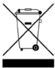
Recycle materials bearing the symbol.
Dispose of packaging in the appropriate recycling containers.
The symbol on the product or its packaging indicates that this product must not be treated as household waste. It should be taken to an appropriate collection point for the recycling of electrical and electronic equipment. By ensuring proper disposal of this product, you help prevent potential negative consequences for the environment and human health that could result from inappropriate waste handling.
For more information about recycling this product, please contact your local authorities, household waste collection center, or the store where you purchased the product.
NOTE : In order to constantly improve our products, we reserve the right to make any changes to their technical, functional or aesthetic.
BELDEKÔ




+33(0)472257706

beldeko@battentier.com