
WHAT102-2CW - Air-conditioner WHIRLPOOL - Free user manual and instructions
Find the device manual for free WHAT102-2CW WHIRLPOOL in PDF.

| Product Type | Through-the-Wall Air Conditioner (Cooling Only) |
| Brand | Whirlpool |
| Model | WHAT102-2CW |
| Cooling Capacity | 10,000 BTU/h |
| Refrigerant | R32 (odorless, flammable) |
| Power Supply | 115 V ~ 60 Hz, 12 A max |
| Rated Power (Recommended Fuse) | 15 A (time-delay circuit breaker) |
| Dimensions (Standard Wall Sleeve) | Height 15 1/4 in, Width 26 in, Depth 16 3/4 in |
| Weight (Estimated) | Approximately 29.5 kg (65 lb) |
| Operating Modes | Cool, Dry, Fan, Auto, Eco, Sleep |
| Timer | Shut-off and delayed start timer from 0.5 h to 24 h |
| Remote Control | Yes, with AAA batteries |
| Air Filter | Washable, cleaning reminder after 500 hours |
| Maintenance | Clean filter every month, clean front panel with damp cloth |
| Safety Feature | Power cord with test/reset (built-in GFCI), overload protection |
| Warranty | 1 year (parts and labor) – limited by XLS Products |
| Repairability | Spare parts available via Whirlpool / XLS Products customer service |
| Installation | Requires standard wall sleeve and 3° rear tilt |
| Country of Origin | Manufactured under license by XLS Products, Pennsylvania, USA |
Frequently Asked Questions - WHAT102-2CW WHIRLPOOL
User questions about WHAT102-2CW WHIRLPOOL
0 question about this device. Answer the ones you know or ask your own.
Ask a new question about this device
Download the instructions for your Air-conditioner in PDF format for free! Find your manual WHAT102-2CW - WHIRLPOOL and take your electronic device back in hand. On this page are published all the documents necessary for the use of your device. WHAT102-2CW by WHIRLPOOL.
USER MANUAL WHAT102-2CW WHIRLPOOL
For questions about features, operation/performance, parts, or service, call: 1-800-207-1156. In Canada, for assistance, installation, or service, call: 1-800-207-1156.
Table of Contents
AIR CONDITIONER SAFETY 2
INTRODUCTION TO REFRIGERANTS R32....3
INSTALLATION REQUIREMENTS....4
Electrical Requirements—All Models 4
Model BTUs—Cooling Only 115 V 8000, 10000, 12000 ....4
Model BTUs—Cooling Only 230 V 10000, 12000, 14000 .... 4
Recommended Grounding Method....4
Power Supply Cord—All Models 5
Tools Required—All Models 5
Packing List 5
Universal Wall—Sleeve Dimensions....6
INSTALLATION INSTRUCTIONS....7
Prepare Air Conditioner for Installation....7
Dual Intake Grille 8
Trim Kit Installation Instructions 9
USING AIR CONDITIONER 10
Turning on the Air Conditioner....10
Selecting the Mode 10
Features....10
Selecting the Fan Speed 10
Adjusting the Temperature....10
Using the Timer 11
Changing Air Direction....11
Normal Operating Sounds....11
Clean Filter Reminder....11
Using the Remote Control....12
Replacing the battery 12
AIR CONDITIONER CARE....13
Air Filter Removal 13
Cleaning the Air Filter 13
Cleaning the Front Panel 13
Repairing Paint Damage....13
Winter Storage....13
TROUBLESHOOTING....14
ASSISTANCE OR SERVICE....15
XLS PRODUCTS WARRANTY FOR WHIRLPOOL® AIR CONDITIONERS 16
Models:
WHAT081-1BW WHAT121-1BW
WHAT101-1BW WHAT122-2BW
WHAT102-2CW WHAT142-2BW
©/TM ©2023 Whirlpool. All rights reserved. Manufactured under license by XLS Products, Pennsylvania. Limited warranty provided by XLS Products.
AIR CONDITIONER SAFETY
Your safety and the safety of others is very important.
We have provided many important safety messages in this manual and on your appliance. Always read and obey all safety messages.

This is the safety alert symbol.
This symbol alerts you to potential hazards that can kill or hurt you and others.
All safety messages will follow the safety alert symbol and either the word "DANGER" or "WARNING."
These words mean:
DANGER
You can be killed or seriously injured if you don't immediately follow instructions.
WARNING
You can be killed or seriously injured if you don't follow instructions.
All safety messages will tell you what the potential hazard is, tell you how to reduce the chance of injury, and tell you what can happen if the instructions are not followed.


IMPORTANT SAFETY INSTRUCTIONS
WARNING: To reduce the risk of fire, electric shock, or injury when using your air conditioner, follow these basic precautions:
■ Plug into a grounded 3 prong outlet.
■ Do not remove ground prong.
■ Do not use an adapter.
■ This appliance is not intended for use by people (including children) whose physical, sensory or mental capacities are different or impaired or who lack the necessary experience or knowledge/expertise to do so, unless such persons are supervised or are trained to operate the appliance by a person who accepts responsibility for their safety.
■ Do not use an extension cord.
■ Unplug air conditioner before servicing.
■ Use two or more people to move and install air conditioner.
■ Do not drink water collected in the water tray.
■ Children should be supervised to ensure that they do not play with the appliance.
SAVE THESE INSTRUCTIONS
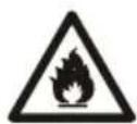
INTRODUCTION TO REFRIGERANTS R32
The refrigerants used in our air conditioners are environmentally safe hydrocarbons. This kind of refrigerant is odorless and combustible, meaning it can burn and explode under certain circumstances. However, there is no danger of burning or exploding if you comply with the below table when installing your air conditioner in a room with an appropriate area and use it correctly.
Compared to ordinary refrigerants, Refrigerant R32 is environmentally friendly, does not destroy the ozone, and has a very little value of greenhouse effect.
Room area requirements for air conditioner with Refrigerant R32
| Refrigerant | Capacity(Btu) | Room Area |
| R32 | ≤9K/12K | Above 4m2(43 sq.ft) |
| ≤18K | Above 15m2(161 sq.ft) | |
| ≤24K | Above 25m2(269 sq.ft) |
WARNING
■ Please read the manual before installation, operation, and maintenance.
■ Do not use means to accelerate the defrosting process or to clean, other than those recommended by the manufacturer.
■ Do not pierce or burn the appliance.
■ The appliance must be stored in a room without continuously operating ignition sources (for example: open flames, an operating gas appliance) and ignition sources (for example: an operating electric heater) close to the appliance.
■ Please contact the nearest after-sale service center when maintenance is necessary. At the time of maintenance, the maintenance personnel must strictly comply with the Operation Manual provided by the corresponding manufacturer and any non-professional is prohibited to maintain the air conditioner.
■ It is necessary to clear away the refrigerant in the system before maintaining or scrapping an air conditioner. Be aware the refrigerant may not contain an odor and is flammable.
■ Unit operation limits: Outdoor side 65\~110°F, 80%RH; indoor side 61\~90°F, 80%RH.
- Keep ventilation openings clear of any obstruction.
■ Any person who is involved with working on or breaking into a refrigerant circuit should hold a current valid certificate from an industry-accredited assessment authority, which monitors their competence to handle refrigerants safely in accordance with an industry recognized assessment specification.
INSTALLATION REQUIREMENTS
Electrical Requirements—All Models
WARNING

Electrical Shock Hazard
Plug into a grounded 3 prong outlet.
Do not remove ground prong.
Do not use an adapter.
Do not use an extension cord.
Failure to follow these instructions can result in death, fire, or electrical shock.
The electrical ratings for air conditioner are listed on the model and serial number label. The model and serial number label is located on the right-hand side of the air conditioner cabinet.
Specific electrical requirements are listed in the "Electrical Requirements" sections. Follow the requirements for the type of plug shown in these sections.
Model BTUs—Cooling Only 115 V 8000, 10000, 12000
All models
■ 115 V - (103.5 min. - 126.5 max.)
If there is a "Single Circuit Only" label on the unit, use on a dedicated single-outlet circuit only.
If a dedicated single-outlet circuit is not available, then it is the customer's responsibility to have a single-outlet circuit installed by a qualified electrician.
If there is no "Single Circuit Only" label on the unit, the unit may be used on any branch circuit of correct voltage and adequate current protection rating.
8,000 BTU 115 V Cooling Only models
0-8 A
■ 10 A time-delay fuse or circuit breaker
0-12 A
■ 15 A time-delay fuse or circuit breaker
10,000-12,000 BTU 115 V Cooling Only models
Model BTUs— Cooling Only 230 V 10000, 12000, 14000
10,000-14,000 BTU 230 V Cooling Only models
■ 230 V (208 min. - 240 max.)
0-9 A
■ 10-15 A time-delay fuse or circuit breaker
Recommended Grounding Method
This air conditioner must be grounded. This air conditioner is equipped with a power supply cord having a grounded 3 prong plug. To minimize possible shock hazard, the cord must be plugged into a mating, grounded 3 prong outlet and grounded in accordance with all local codes and ordinances. If a mating outlet is not available, it is the customer's responsibility to have a properly grounded 3 prong outlet installed by a qualified electrical installer. It is the customer's responsibility:
■ To contact a qualified electrical installer.
■ To assure that the electrical installation is adequate and in conformance with National Electrical Code, ANSI/NFPA 70—latest edition, and all local codes and ordinances.
Copies of the standards listed may be obtained from:
National Fire Protection Association
1 Batterymarch Park
Quincy, MA 02269
Power Supply Cord—All Models
WARNING

Electrical Shock Hazard
Plug into a grounded 3 prong outlet.
Do not remove ground prong.
Do not use an adapter.
Do not use an extension cord.
Failure to follow these instructions can result in death, fire, or electrical shock.
NOTE: The air conditioner's power supply cord may differ from those shown.
The air conditioner is equipped with a power supply cord that is required by UL. This power supply cord contains state-of-the-art electronics that sense leakage current. If the cord is damaged, the electronics detect leakage current and power will be disconnected in a fraction of a second.
To test your power supply cord:
- Plug power supply cord into a grounded 3 prong outlet.
- Press RESET (on some models, a green light will turn ON).
- Press TEST (listen for click; Reset button will trip, and on some devices, a green light will turn OFF).
- Press and release RESET (listen for click; Reset button will latch, and on some devices, a green light will turn ON). The power supply cord is ready for operation.
NOTES:
■ The Reset button must be pushed in for proper operation.
■ The power supply cord must be replaced if it fails to trip when the test button is pressed or fails to reset.
■ Do not use the power supply cord as an OFF/ON switch. The power supply cord is designed as a protective device.
A damaged power supply cord must be replaced with a new power supply cord obtained from the product manufacturer and must not be repaired.
■ The power supply cord contains no user-serviceable parts. Opening the tamper-resistant case voids all warranty and performance claims.
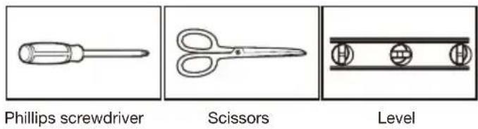
Tools Required—All Models
Gather the required tools and parts before starting installation. Read and follow the instructions provided with any tools listed here.
Tape measure
Cordless drill and 3/16" bit
Pencil
1/8"Drill bit
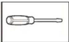
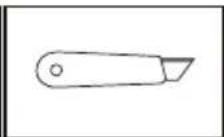
Flathead screwdriver Putty knife
Packing List
| IMAGE PART QUANTITY | ||
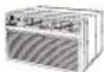 | Through-The-Wall Air Conditioner | 1 |
 | Remote Control | 1 |
 | Trim Frame 1 (Left & Right legs) | 2 |
 | Trim Frame 2 (Top & Bottom legs) | 2 |
 | Grille Aluminum | 1 |
 | Rear plastic net | 1 |
| DAWWD | 1/2" Long Hex-head Screw | 4 |
 | Grounding wire with tooth washer | 1 |
DIMENSIONS PART QUANTITY
| 1" x 3/4" x 14" Seal Sponge 2 | ||
| 1" x 3/8" x 14" Seal Sponge 2 | ||
| 1" x 3/8" x 25" Seal Sponge 3 | ||
| 1" x 1 12 "x 25" Seal Sponge 3 | ||
| 1" x 1 12 " x 14" Seal Sponge 2 | ||
| 1" x 1 12 " x 84" Seal Sponge 1 | ||
| 3 34 " x 1 12 " x 4" Seal Cotton 4 | ||
| 3/4" x 1 12 " x 17" Seal Cotton 2 |
Universal Wall—Sleeve Dimensions
- Identify the wall-sleeve brand installed in the wall, and make sure that dimensions of wall-sleeve are as per the below table:
| Type | Wall-sleeve Dimensions | ||
| Height W | dth Depth | ||
| Standard Dimension 15 34 " | 26" 16 34 " | ||
NOTE:
■ All wall sleeves used to mount the new air conditioner must be in sound structural condition and have a rear grille that securely attaches to the sleeve, or rear flange that serves as a stop for the air conditioner.
If non-Whirlpool brand wall-sleeve installed, make sure that the dimension is suitable for the product.
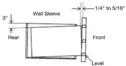
■ The selected wall-sleeve must be installed and fastened to the wall with the screws. Be sure that there will be a 3 tilt angle backward.
IMPORTANT: When the installation is complete, a replacement unit must have rearward slope as shown in below figure:
- Remove the old air conditioner from the wall sleeve and prepare as follows:
■ Clean interior (Do not disturb seals).
■ Check the wall sleeve to make sure that it is securely attached to the wall before installing.
■ Repair painted surface if needed.
- If the ground wire hole does not exist, drill a 3/16" pilot hole for the ground screw through the left hand side of the sleeve, in a clear area about 3 inches max. back from the front edge as shown in the below figure:
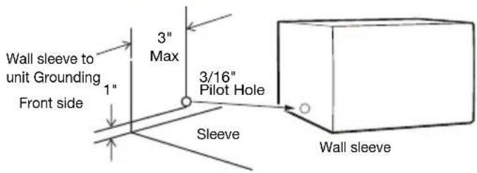
- Pull the loose end of the ground wire out of the front of the sleeve and bend it away from the opening. This will be attached to the air conditioner once installed.
INSTALLATION INSTRUCTIONS
Prepare Air Conditioner for Installation
WARNING
Excessive Weight Hazard
Use two or more people to move and install air conditioner.
Failure to do so can result in back or other injury.
1. Unpack the Air Conditioner
natural_image
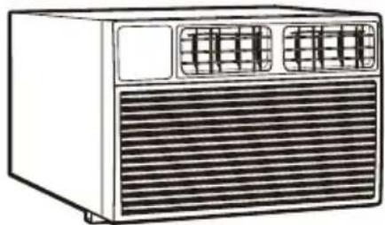
Line drawing of a portable air conditioner unit with ventilation grilles and ventilation grilles (no text or symbols)Remove Packaging Materials:
■ Gently handle the air conditioner while unpacking the unit.
■ Place the air conditioner on a hard, flat surface.
■ Remove tape and glue residue from surfaces before turning ON the air conditioner. Rub a small amount of liquid dish soap over the adhesive with the fingers. Wipe with a damp cloth and dry.
Do not use sharp instruments, rubbing alcohol, flammable fluids, or abrasive cleaners to remove tape or glue. These products can damage the surface of the air conditioner.
■ Dispose of/recycle packaging materials in an appropriate way.
2. Removal of the Old Grille
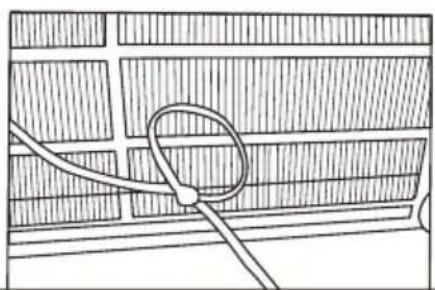
natural_image
Simple line drawing of a rope tied to a circular object on a grid-patterned surface (no text or symbols)NOTE: Single intake grille must be removed when used with the dual intake Through The Wall (TTW) unit.
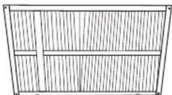
natural_image
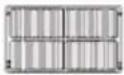
Simple line drawing of a rectangular frame with vertical slats and a horizontal panel (no text or symbols)Single intake grille
IMPORTANT:
While removing the old grille, please hold it to
prevent it from falling.
While holding the grille by the leash with one hand, the retaining screws can be removed and the grille can be brought inside through the front of the sleeve as shown below.
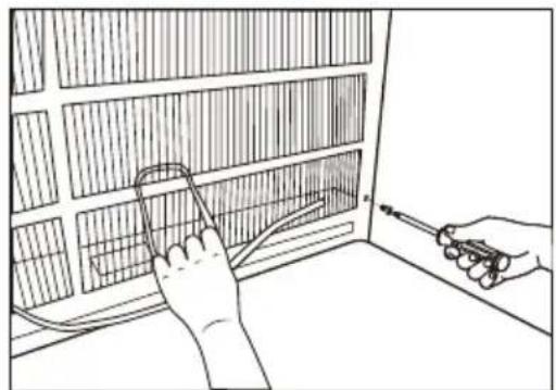
natural_image
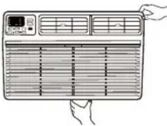
Line drawing of a hand using a tool to connect electrical wiring inside a grid-patterned cabinet (no text or symbols)3. Installation of the New Grill
New Dual Intake Grille
NOTES:
This unit's increased performance characteristics are the result of having two rear intakes.
It is very important that installation instructions are followed so the unit can operate at maximum efficiency.
■ If there is an existing sleeve and rear grille, check whether the dimensions are correct, otherwise replace them.
Existing Sleeves may have older single-sided intake grilles.
Single-sided intake grilles must be replaced with the dual intake grille type as shown in the above figure.
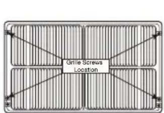
■ Remove the existing grille and save the mounting screws.
■ Place the grille included with the new air conditioner towards the inside rear of the sleeve.
■ Attach the new grille by aligning the four mounting holes.
■ Re-insert the self-tapping screws into the nylon retainers.
- Direct Unit Mounting
In cases, where the dual intake grille cannot be mounted directly to the sleeve it is desirable to attach the grille to the back of the TTW unit to the hole predrilled in the unit.
- Attach the 2 seals (1" x 3/8" x 14"), as shown in above figure.
- Position the grille over the rear of the unit to make sure that:
■ The double set of screw holes are at the bottom.
■ The intake fins on either side are pointed away from the unit.
- Align the top of the grille with the top of the unit. The overhang on each side is equal.
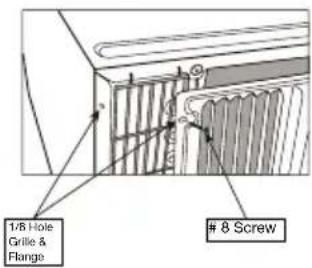
- If the unit has not been predrilled (some models), drill 4-1/8" holes through the grille and into the side flange of the unit approximately 1½" to 2" from the top and bottom, as shown in below figures. (Do not break the copper pipe.)
- Install 4-#8 self-tapping screws to affix the grille to the unit.
-
Insert the unit into the sleeve.
-
Install the Seal
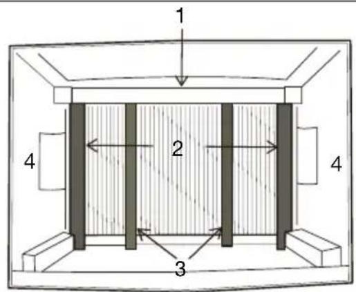
- Install the 1" x 3/8" x 25" long seal in the center at the top of the sleeve. Remove the back paper and press into position.
- Install the 1" x 3/8" x 14" seals to the left and right sides of the sleeve.
- Cut the 1" x 3/8" x 25" long seals to 14" long each and attach to the vertical sections of the grille.
- Install the 1/2" x 3½" x 1½" centering blocks one on each side wall. Place in center of side wall with the tapered end facing the opening.
- Gently slide unit into sleeve.
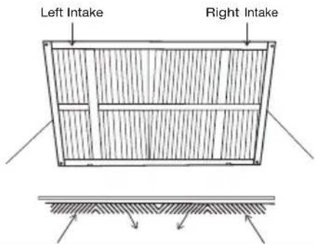
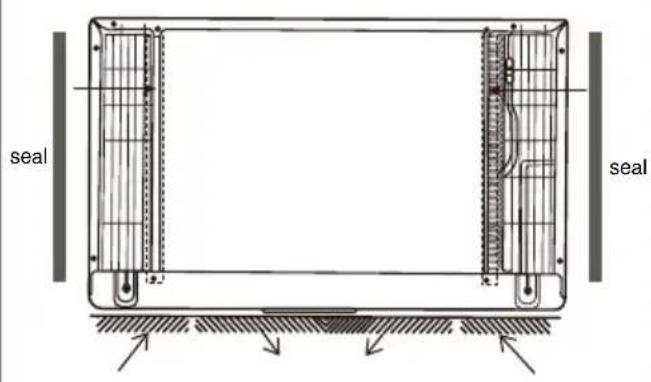
Dual Intake Grille
In cases, where the existing sleeve is a dual intake grille, the existing grille may be left in place.
Make sure the outer 3½" to 4½" louvers are angled from the left and right sides of the sleeve toward the center, as shown in below figure. This provides proper flow of outside air into the unit.
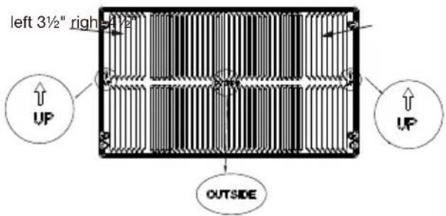
From the installation kit, apply two 1" x 3/4" x 14" seals along the flat metal flange of the unit, as shown in below figure:
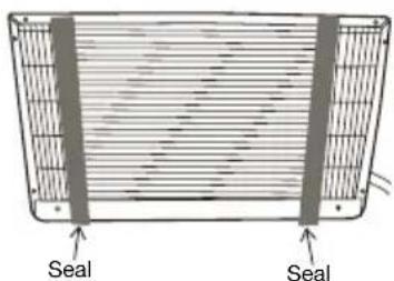
Insert the unit with the seals attached into the sleeve pushing it all the way to the rear, making sure the seals are against the rear grille. The seals are necessary to reduce recirculation of hot air into the intakes which would reduce system performance.
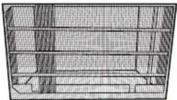
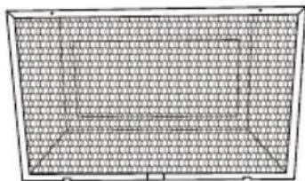
natural_image
Cross-sectional diagram of a mechanical or architectural structure with layered components (no text or symbols visible)An option is to purchase 3/4" diamond cut aluminum grille and cut it to fit inside the sleeve. Secure it with screws. Attach the dual intake grill directly to the back of the unit. Slide the entire unit into the sleeve.
natural_image
Grid-patterned panel with no visible text, numbers, or symbols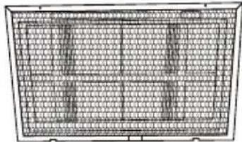
natural_image
Grid-patterned diagram of a rectangular grid structure with vertical bars, no text or symbols presentTrim Kit Installation Instructions
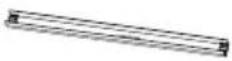
- Install the 1" x 1½" x 84" long stuffer seal between the wall sleeve and the unit. A flat-bladed screwdriver or putty knife is needed.
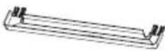
- Assemble the trim frame by inserting the top and bottom pieces into side pieces and snapping into place.
- Pull the power cord through the trim frame and slide the trim over the unit until flush with the wall.
natural_image
Line drawing of a hand inserting a fan into an air conditioner unit (no text or symbols)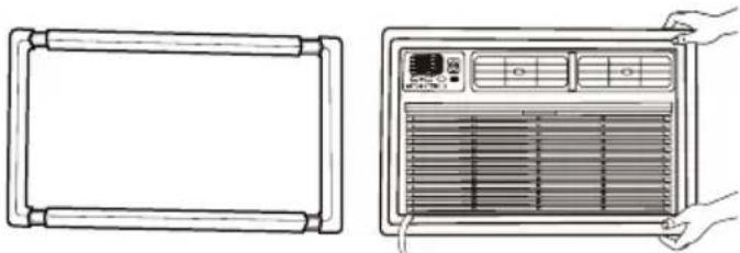
natural_image
Line drawing of two views of an air conditioner unit with a handle and control panel (no text or symbols)Energy saving suggestion: In order to reach the maximum energy saving and comfortability, it is necessary to use an appropriately sized cover to provide additional insulation and air sealing when the unit is not in use during the off-using-season.
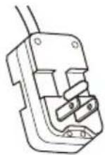
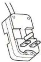
6. Install Ground Wire
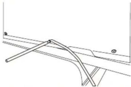
natural_image
Pure technical line drawing of a mechanical assembly without any text, numbers, or symbols- Attach the one end of the ground wire inside the sleeve with the screw according to preparation instruction.
- Before sliding unit all the way back remove the second screw (2/5" screw) from the left side of the unit.
- Remove the plastic washer from the screw.
- Attach the other end of the ground wire to the unit with screw as shown above. Make sure that the toothed washer is against the cabinet.
- Slide unit completely to the rear.
USING AIR CONDITIONER
Operating the air conditioner properly helps you to obtain the best possible results.
This section explains proper air conditioner operation.
IMPORTANT:
If you turn OFF the air conditioner, wait at least 3 minutes before turning it back on. This is to avoid the air conditioner from blowing a fuse or tripping a circuit breaker.
■ Do not try to operate the air conditioner in the Cool mode when the outside temperature is below 65^ F ( 18^ C). The inside evaporator coil will freeze up, and the air conditioner will not operate properly.
NOTE: In the event of a power failure, the air conditioner will operate at the previous settings when the power is restored.
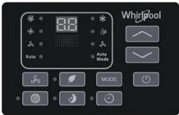
Turning on the Air Conditioner
- Press POWER to turn ON the air conditioner.
- Press POWER to turn OFF the air conditioner.
Selecting the Mode
- Press MODE button to cycle through the various modes.
- Choose modes: Cool, Dry, or Fan.
- (*)Cool: The cooling function allows the air conditioner to cool the room and at the same time reduces air humidity. Press the MODE button to set the cooling function. Press the up or down arrow button to adjust the temperature.
■ (✗)Dry: This function reduces the humidity of the air to make the room more comfortable. Press MODE button to set the DRY mode. An automatic function of alternating cooling cycles and air fan is activated.
■ (S)Fan : In this mode, only the fan runs to provide ventilation. Press MODE button to set the FAN mode. Press S(FAN SPEED)to select High, Med, or Low.
NOTE: After 5 seconds, the display will show the current room temperature.

Features
■ ( )ECO:Conserves energy by turning off compressor when the room reaches the desired temperature. The fan motor will run for 1 minute, stop for 5 minutes, then run again. The compressor will turn back on when the room temperature rises above the set temperate Press ECO to turn Eco feature on and off. When the unit is in Eco mode, the light will turn on.

■ (:) SLEEP: Automatically adjusts the temperature (SLEEP) and fan speed to make the room more comfortable during the night. Press and hold the (SLEEP) button until the sleep light turns on. All other lights will turn off.

The set temperature will automatically increase by 1 degree every 30-60 minutes. At the end of the sleep cycle, the temperature will switch back to the originally set temperature.
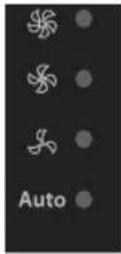
Selecting the Fan Speed
- Press FAN SPEED button until the LED indicator for the desired setting is lit.
- Choose Low, Med, or High.
■ (∞) Low—Low fan speed
■ (✗) Med—Normal fan speed
■ (※) High—Maximum fan speed
NOTES:
(Auto) Auto-Auto fan speed and temperature cannot be selected in Fan Only mode.
■ In SLEEP modes, Auto fan speed is selected automatically.
Adjusting the Temperature
Press the up arrow button to increase the set temperature.

Press the down arrow button to decrease the set temperature.

Using the Timer
Delayed Shutoff:
Use the Ⓐ(TIMER) button to set the air conditioner to turn off automatically after 0.5- to 24-hour delay (the air conditioner must be on):

- Press ⏻(TIMER) button. The display will show remaining time before the air conditioner will turn off.
- Press the up or down arrow button to change the delayed shutoff time from 0.5 to 24 hours. The time can be set in 0.5-hour increments below 10 hours and 1-hour increments for 10 hours or above.
- Press ⏻(TIMER)button again to confirm setting.
NOTE: The Set light will turn on while setting.
Delayed Start:
It can be set to automatically turn off or on in 0.5-24 hours delay.
NOTE: After the set delay, the air conditioner will turn on with the previous settings. Change the mode, fan speed, and/or temperature before setting the timer, if desired.
- Turn off the air conditioner.
- Press Ⓐ(TIMER) button. Set the temperature by pressing the up or down arrow button.
- Press Ⓐ(TIMER) button a second time to set the rest time. Press the up or down arrow button to change the delay time from 0.5 to 24 hours.
- Press☑(TIMER) button again while the time remaining is shown on the display.
To Cancel Timer:
After the timer has been set, press ⏻(TIMER)button.
Changing Air Direction
Use of the Directional Louvers
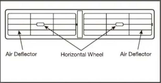
To direct the airflow, use the horizontal wheel to control the horizontal direction and the air deflector to control the vertical direction.
Normal Operating Sounds
When the air conditioner is operating normally, you may hear sounds such as:
■ Droplets of water hitting the condenser, causing a pinging or clicking sound. The water droplets help cool the condenser.
■ Air movement from the fan.
■ Clicks from the thermostat cycle.
■ Vibrations or noise due to loose material in the wall or window construction.
■ A high-pitched hum or pulsating noise caused by the modern high-efficiency compressor cycling ON and OFF.
■ Water will collect in the base pan during rain or days of high humidity. The water may overflow and drip from the outside part of the unit.
Clean Filter Reminder
To help maximize energy efficiency, this air conditioner features a Clear Filter reminder.
After 500 hours of operation, FILTER will illuminate as a reminder that it is time to clean the filter. After cleaning the filter, pressing the FILTER button will turn off the light and reset the filter timer. See the "Air Conditioner Care" section for instructions on how to clean the filter.

Using the Remote Control
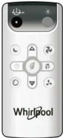
(⏻) POWER
- Press POWER to turn ON the air conditioner.
- Press POWER to turn OFF the air conditioner.
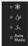
(★)COOL
Press COOL to enter Cool mode.
( )FAN SPEED
- Press FAN SPEED until the bar LED on the air conditioner control panel display for the desired setting.
- Choose Low, Medium, or High.
NOTES:
■ Auto fan speed and Temperature cannot be selected in Fan mode.

(①)Eco
(ECO)ECO:Conserves energy by turning off compressor when the room reaches the desired temperature. The fan motor will run for 1 minute, stop for 5 minutes, then run again. The compressor will turn back on when the room temperature rises above the set temperature. Press ECO to turn Eco feature on and off. When the unit is in Eco mode, the light will turn on.

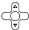
Adjusting Temperature
Press the up arrow button to increase the set temperature. Press the down button to decrease the set temperature.
( )SLEEP
Automatically adjusts the temperature and fan speed to make the room more comfortable during the night. Press and hold the Ⓐ(SLEEP) button until the sleep light turns on. All other lights will turn off. The set temperature will automatically increase by 1 degree every 30-60 minutes. At the end of the sleep cycle, the temperature will switch back to the originally set temperature.

( TIMER )
Delayed Shutoff:
Use the timer to set the air conditioner to turn off automatically after a 0.5- to 24-hour delay the air conditioner must be ON):

- Press Ⓜ(TIMER).The display will show remaining time before the air conditioner will turn OFF.
- Press the up or down arrow button to change the delayed shut-off time from 0.5 to 24 hours. The time can be set in 0.5-hour increments below 10 hours and 1-hour increments for 10 hours or above.
- Press Ⓛ (TIMER) again to confirm setting. NOTE: The Set light will turn on while setting.
Delayed Start:
You can also set the air conditioner to turn on automatically after a 0.5- to 24-hour delay.
NOTE: After the set delay, the air conditioner will turn on with the previous settings. Change the mode, fan speed, and/or temperature before setting the timer, if desired.
- Turn OFF the air conditioner.
- Press ⏻(TIMER). Set the temperature by pressing the up or down arrow button.
- Press ⏻ (TIMER) a second time to set the rest time. Press the up or down arrow button to change the delay time from 0.5 to 24 hours.
- Press ⏻ (TIMER) again while the time remaining is shown on the display.
To Cancel Timer:
After the timer has been set, press Ⓛ (TIMER).
(©) AUTO:
Press AUTO MODE to enter into Auto mode. In this mode, the fan speed and temperature are set automatically according to the room temperature as tested by the indoor temperature sensor.

( )DISPLAY:
Press DISPLAY to switch on/off all lights or the LED display.

(\_)Fan Only:
Press the Fan Only button to enter Fan Only mode.

Replacing the battery
Remove and replace batteries
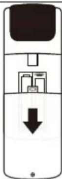
natural_image
Diagram of a mobile phone with a black downward arrow indicating a download or download process (no text or symbols present)Use a small Phillips screwdriver to loosen the battery cover screw. Slide the battery cover down with two thumbs to remove. Remove and properly dispose of old batteries, then replace with two new AAA batteries. Replace the battery cover and tighten the screw.
AIR CONDITIONER CARE
The air conditioner is designed to give you many years of dependable service. This section tells you how to clean and care for your air conditioner properly.
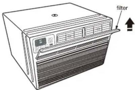
Air Filter Removal
The air filter is located behind the intake grille of air conditioner. Remove the air filter as follows:
■ Remove the filter by pulling down the indents of the filter door on the front of the unit as shown in below figure.
Cleaning the Air Filter
The air filter is removable for easy cleaning. A clean filter helps remove dust, lint, and other particles from the air and is important for the best cooling and operating efficiency. Check the filter at least once per month to see whether it needs cleaning.
NOTE: Do not operate the air conditioner without the filter in place. Doing so will degrade the unit performance over time.
- Use a vacuum cleaner to clean the air filter.
- If the air filter is very dirty, use the liquid dish soap and warm water to wash the filter.
- Rinse the filter properly and shake the filter gently to remove the excess water.
- Let the filter dry completely before placing it into the air conditioner to ensure maximum efficiency.
NOTE: Do not wash the air filter in the dishwasher or use any chemical cleaners; it may damage the filter.
Cleaning the Front Panel
- Unplug the air conditioner.
- Wipe the front panel with a soft, damp cloth.
- Air dry the front panel completely.
Repairing Paint Damage
Check once or twice a year for paint damage. This is very important, especially in areas near salt water or where rust is a problem. If needed, touch up with a good grade enamel paint.
Winter Storage
Cover the air conditioner with an appropriate cover to block outside air flow and to provide insulation.
TROUBLESHOOTING
Before calling for service, try the suggestions below to see whether you can solve problem without outside help.
WARNING

Electrical Shock Hazard
Plug into a grounded 3 prong outlet.
Do not remove ground prong.
Do not use an adapter.
Do not use an extension cord.
Failure to follow these instructions can result in death, fire, or electrical shock.
| PROBLEM POSSIBLE CAUSES RECOMMENDED SOLUTIONS | ||
| The Air Conditioner Will Not Start | The air conditioner is unplugged. Make sure that the power supply cord is plugged into a grounded 3 prong outlet. | |
| The fuse is blown/circuit breaker is tripped. Check the house fuse/circuit breaker box and replace the fuse or reset the breaker. | ||
| Power failure. The unit will automatically restart when power is restored. There is a protective time delay (approximately 3 minutes) to avoid tripping of the compressor overload. The unit may not start normal cooling for 3 minutes after it is turned back on. | ||
| The power cord reset button is tripped. Press the reset button located on the power cord plug. If the reset button will not stay engaged, discontinue use of the air conditioner and contact a qualified service technician. | ||
| The Air Conditioner Is Not Cooling Properly | Airflow is restricted. | Make sure that there are no curtains, blinds, or furniture blocking the front of the air conditioner. |
| The temperature control is not set correctly. Lower the set thermostat temperature. | ||
| The air filter is dirty. | Clean the filter. See the “Air Conditioner Care” section. | |
| The room is too warm. Allow time for the room to cool down after turning on the room air conditioner. | ||
| Cold air is escaping. Close all open doors and for windows where warm air may be entering. | ||
| The cooling coils are frozen. See “The Air Conditioner Is Freezing Up” below. | ||
| The Air Conditioner Is Freezing Up | Ice is blocking the airflow. | Turn off the unit and allow it to thaw until the ice has melted, then operate on a higher fan speed. If this continues to occur, contact customer service for additional help. |
| The Remote Control Is Not Working | Batteries are inserted incorrectly. Check that the batteries are inserted in the correct direction. | |
| Batteries are dead. Replace the batteries and dispose of them in a responsible manner. | ||
| Water Is Dripping From the Unit on the Outdoor Side | The weather is hot and humid. This is normal during periods of high humidity.NOTE: Do not drill a hole into the bottom of the metal base pan; doing so will reduce cooling performance. | |
| Water Is Dripping Inside the Room | The air conditioner is not properly leveled. The air conditioner should slope slightly downward toward the outside. Level the air conditioner to provide a downward slope toward the outside to ensure proper drainage. See the “Installation Instructions” section.NOTE: Do not drill a hole into the bottom of the metal base pan; doing so will reduce cooling performance. | |
| Water Collects in the Base Pan | Moisture removed from the air is collecting in the base pan. | This is normal. Water that collects in the base pan will evaporate to the outside air. This helps with the unit's cooling process.NOTE: Do not drill a hole into the bottom of the metal base pan; doing so will reduce cooling performance. |
| Digital display reads "E1", "E2" | A sensor has failed. Contact customer service | |
ASSISTANCE OR SERVICE
Before calling for assistance or service, please check the "Troubleshooting" section. It may save you the cost of a service call. If you still need help, follow the instructions below.
When calling, please have the delivery date and the complete model and serial numbers of the appliance. This information will help us to better respond to the request.
In the USA
Call XLS Products Customer Service toll free: 1-800-207-1156.
Our consultants provide assistance with:
■ Features and specifications on our full line of appliances.
■ Installation information.
■ Use and maintenance procedures.
■ Accessory and repair parts.
■ Specialized customer assistance.
■ Referrals to local dealers, repair parts distributors, and service companies. XLS Products-designated service technicians are trained to fulfill the product warranty and provide after-warranty service, anywhere in the United States.
For further assistance:
If you need further assistance, you can write to XLS Products with any questions or concerns at:
XLS Products, Inc.
Customer Service
P.O. Box 16262
Philadelphia, PA 19114-0262
Please include a daytime phone number in your correspondence.
In Canada
Call XLS Products Customer Service toll free: 1-800-207-1156.
Our consultants provide assistance with:
■ Features and specifications on our full line of appliances.
■ Use and maintenance procedures.
■ Accessory and repair parts.
■ Referrals to local dealers, repair parts distributors, and service companies. XLS Products-designated service technicians are trained to fulfill the product warranty and provide after-warranty service, anywhere in Canada.
For further assistance:
If you need further assistance, you can write to XLS Products with any questions or concerns at:
XLS Products, Inc.
Customer Service
P.O. Box 16262
Philadelphia, PA 19114-0262
Please include a daytime phone number in your correspondence.
XLS PRODUCTS WARRANTY FOR WHIRLPOOL® AIR CONDITIONERS
ONE YEAR LIMITED WARRANTY
For one year from no earlier than date of delivery, when this product is operated and maintained according to instructions attached to or furnished with the product, XLS Products will pay for product replacement (at our discretion) to correct defects in materials or workmanship.
ITEMS XLS PRODUCTS WILL NOT PAY FOR
- Service calls to correct the installation of your product, instruct you how to use your product, to replace house fuses or reset circuit breakers, replace or clean filters, or correct house wiring.
- Service calls to repair or replace air filters. Those consumable parts are excluded from warranty coverage.
- Repairs when your product is used for other than normal, single-family household use.
- Damage resulting from accident, alteration, misuse, abuse, fire, flood, acts of God, improper installation, installation not in accordance with electrical or plumbing codes, or use of products not approved by XLS Products.
- Replacement parts or repair labor costs for units operated outside the United States or Canada.
- Pickup and delivery. This product is designed to be repaired in the home.
- Repairs to parts or systems resulting from unauthorized modifications made to the appliance.
- Expenses for travel and transportation for product service in remote locations.
- The removal and reinstallation of your appliance if it is installed in an inaccessible location or is not installed in accordance with published installation instructions.
DISCLAIMER OF IMPLIED WARRANTIES; LIMITATION OF REMEDIES
CUSTOMER'S SOLE AND EXCLUSIVE REMEDY UNDER THIS LIMITED WARRANTY SHALL BE PRODUCT REPAIR AS PROVIDED HEREIN. IMPLIED WARRANTIES, INCLUDING WARRANTIES OF MERCHANTABILITY OR FITNESS FOR A PARTICULAR PURPOSE, ARE LIMITED TO ONE YEAR OR THE SHORTEST PERIOD ALLOWED BY LAW. XLS PRODUCTS SHALL NOT BE LIABLE FOR INCIDENTAL OR CONSEQUENTIAL DAMAGES. SOME STATES AND PROVINCES DO NOT ALLOW THE EXCLUSION OR LIMITATION OF INCIDENTAL OR CONSEQUENTIAL DAMAGES, OR LIMITATIONS ON THE DURATION OF IMPLIED WARRANTIES OF MERCHANTABILITY OR FITNESS, SO THESE EXCLUSIONS OR LIMITATIONS MAY NOT APPLY TO YOU. THIS WARRANTY GIVES YOU SPECIFIC LEGAL RIGHTS AND YOU MAY ALSO HAVE OTHER RIGHTS, WHICH VARY, FROM STATE TO STATE OR PROVINCE TO PROVINCE.
Outside the 50 United States and Canada, this warranty does not apply. Contact your authorized XLS Products dealer to determine if another warranty applies.
If you need service, first see the "Troubleshooting" section of the Use & Care Guide. After checking "Troubleshooting," additional help can be found by checking the "Assistance or Service" section or by calling XLS Products. In the U.S.A., call 1-800-207-1156. In Canada, call 1-800-207-1156.
Keep this book and your sales slip together for future reference. You must provide proof of purchase or installation date for in-warranty service.
Write down the following information about your air conditioner to better help you obtain assistance or service if you ever need it. You will need to know your complete model number and serial number. You can find this information on the model and serial number label located on the product.
Dealer name ____
Address
Phone number
Model number ____
Serial number
Purchase date
INSTRUCTIONS D'INSTALLATION....23
ASSISTANCE OU SERVICE....31
GARANTIE DE XLS PRODUCTS POUR LES CLIMATISEURS WHIRLPOOL ^ 32
Modèles :
WHAT081-1BW WHAT121-1BW
WHAT101-1BW WHAT122-2BW
WHAT102-2CW WHAT142-2BW
SÉCURITÉ DU CLIMATISEUR
National Fire Protection Association
1 Batterymarch Park
Quincy, MA 02269
DIMENSIONS PIÈCE QUANTITÉ
| 1 po x 3/4 po x 14 po | Joint (matériau de mousse) | 2 |
| 1 po x 3/8 po x 14 po | Joint (matériau de mousse) | 2 |
| 1 po x 3/8 po x 25 po | Joint (matériau de mousse) | 3 |
| 1 po x 1 1⁄2 po x 25 po | Joint (matériau de mousse) | 3 |
| 1 po x 1 1/2 po x 14 po | Joint (matériau de mousse) | 2 |
| 1 po x 1 1/2 po x 84 po | Joint (matériau de mousse) | 1 |
| 3 3/4 po x 1 1/2 po x 4 po | Joint (coton) 4 | |
| 3/4 po x 1 1/2 po x 17 po | Joint (coton) 2 |
Dimensions de la gaine murale universelle
natural_image
Line drawing of a portable air conditioner unit with ventilation grilles (no text or symbols)natural_image
Simple line drawing of a rope tied to a circular object on a grid-patterned surface (no text or symbols)natural_image
Simple line drawing of a rectangular frame with vertical hatching and a central horizontal bar (no text or symbols)natural_image
Line drawing of a hand using a tool to interact with a grid-patterned panel or panel (no text or symbols present)natural_image
Pure technical diagram of a grid-patterned structure without any text, numbers, or symbolsnatural_image
Pure grid pattern with no text, numbers, or symbols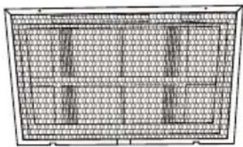
natural_image
Pure architectural grid layout without any text, numbers, or symbolsnatural_image
Line drawing of an air conditioner unit with hand pointing to the front panel (no text or symbols)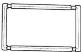
natural_image
Simple line drawing of a rectangular frame with rounded corners and no text or symbols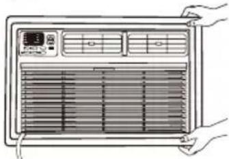
natural_image
Line drawing of a front panel with ventilation grilles and control buttons, hands adjusting the panel (no text or symbols)natural_image
Pure technical line drawing of a mechanical assembly without any text, numbers, or symbolsnatural_image
Diagram of a mobile phone with a black downward arrow indicating a download or download process (no text or symbols present)ASSISTANCE OU SERVICE
Philadelphia, PA 19114-0262
Philadelphia, PA 19114-0262
GARANTIE DE XLS PRODUCTS POUR LES CLIMATISEURS WHIRLPOOL®
GARANTIE LIMITÉE DE UN AN
Au Canada, composer le 1 800 207-1156.
WHAT081-1BW WHAT121-1BW
WHAT101-1BW WHAT122-2BW
WHAT102-2CW WHAT142-2BW
SEGURIDAD DEL ACONDICIONADOR DE AIRE
National Fire Protection Association
1 Batterymarch Park
Quincy, MA 02269
natural_image
Line drawing of a portable air conditioner unit with ventilation grilles and ventilation grilles (no text or symbols)natural_image
Simple line drawing of a rope tied to a circular object on a grid-patterned surface (no text or symbols)natural_image
Simple line drawing of a rectangular frame with vertical lines and a central horizontal bar (no text or symbols)natural_image
Line drawing of hands using a tool to adjust or install a grid panel inside a cabinet (no text or symbols)natural_image
Technical line drawing of a mechanical component or housing (no text or symbols)natural_image
Pure geometric grid pattern with no text, numbers, or symbols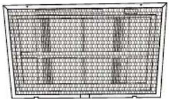
natural_image
Pure architectural grid layout without any text, numbers, or symbolsnatural_image
Line drawing of an air conditioner unit with hand and panel, no text or symbols present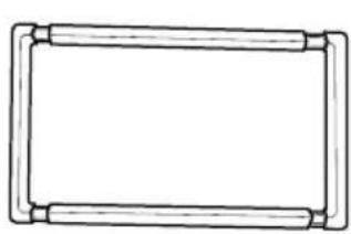
natural_image
Simple line drawing of a rectangular frame with rounded corners (no text or symbols)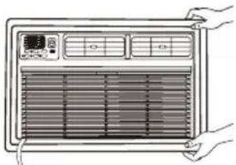
natural_image
Illustration of a front panel with heat exchanger and ventilation grilles, held by hands (no text or symbols)natural_image
Pure technical line drawing of a mechanical assembly without any text, numbers, or symbols(⊕) Encendido
natural_image
Diagram of a mobile phone showing internal components and a downward arrow (no text or symbols)Philadelphia, PA 19114-0262
Philadelphia, PA 19114-0262
©/TM ©2023 Whirlpool. All rights reserved. Manufactured under license by XLS Products, Pennsylvania. Limited warranty provided by XLS Products.