Airstar H-C1 M - Hair Dryers Starmix - Free user manual and instructions
Find the device manual for free Airstar H-C1 M Starmix in PDF.

User questions about Airstar H-C1 M Starmix
0 question about this device. Answer the ones you know or ask your own.
Ask a new question about this device
Download the instructions for your Hair Dryers in PDF format for free! Find your manual Airstar H-C1 M - Starmix and take your electronic device back in hand. On this page are published all the documents necessary for the use of your device. Airstar H-C1 M by Starmix.
USER MANUAL Airstar H-C1 M Starmix
natural_image
Exterior view of a modern office building (no signage)Bedienungsanleitung (original)
Operating instructions
en Operating Instructions (translation)......17
text_image
Technical diagram of a mechanical device with labeled parts 1 and 2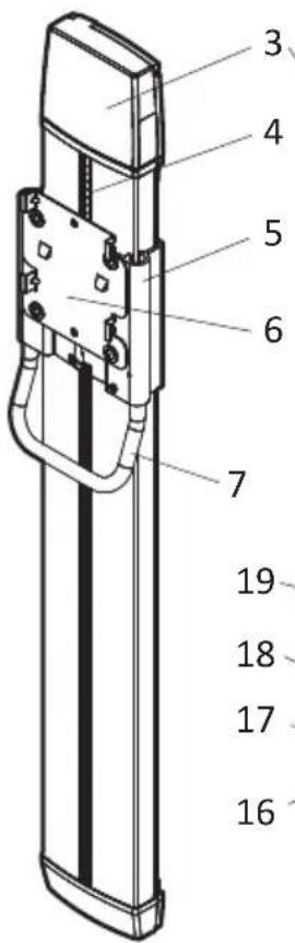
text_image
3 4 5 6 7 19 18 17 16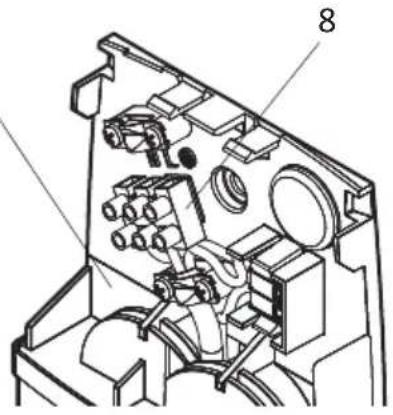
text_image
Technical diagram of a mechanical device with numbered components, likely an optical or mechanical assembly.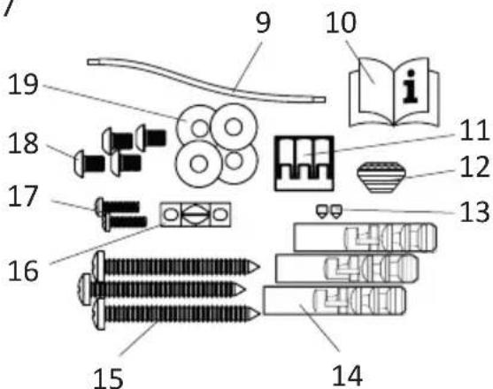
text_image
Labeled diagram of household items with numbered parts, including books, personal items, and a book iconB
text_image
133 mm 1038 mm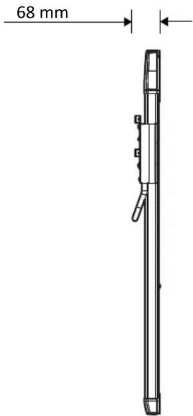
text_image
68 mmC
text_image
1200 mm 600 mm 600 mm 1200 mmD
text_image
Technical diagram showing three labeled mechanical assembly steps with directional arrows and numbered componentsE
natural_image
Diagram showing two directional arrows pointing to a rectangular object, with a pipe or duct in the background (no text or symbols)F
1
natural_image
Technical line drawing of a mechanical device with a handle and internal components (no text or symbols)2
natural_image
Illustration of a handheld electric shaver with two circular components (no text or symbols)3
natural_image
Technical line drawing of a mechanical device with no visible text or symbolsG
text_image
Diagram illustrating the assembly of a device with numbered components and directional arrows indicating assembly steps.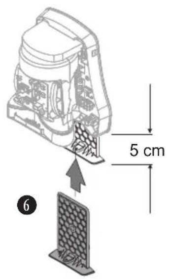
text_image
5 cm 6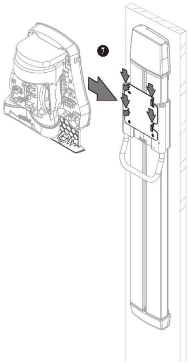
text_image
Technical diagram showing a device's internal structure before and after assembly, with labeled component 7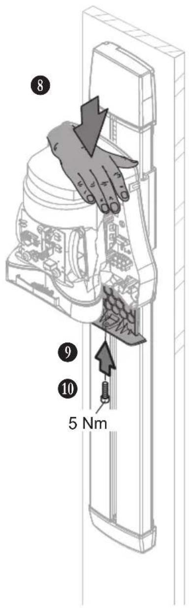
text_image
8 9 10 5 NmH
natural_image
Technical diagram of a mechanical or electrical component with internal wiring and connectors (no text or symbols)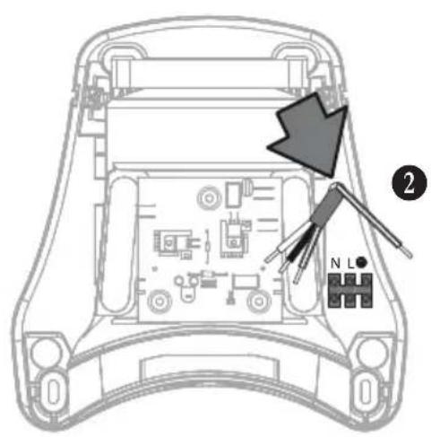
text_image
Diagram of a car's front panel with labeled components and directional arrow indicating movement or forceI
text_image
Diagram showing electrical connections with labeled components and directional arrows, likely illustrating a power or signal routing setup.J
text_image
Diagram illustrating the assembly of a device with numbered parts and directional arrows indicating components.K
text_image
Diagram illustrating the process of assembling electronic components, showing disassembly and assembly steps with labeled parts.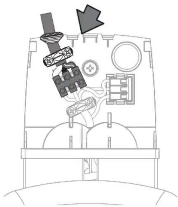
natural_image
Diagram of a vehicle's internal components with no visible text or symbols1 Important safety information
Carefully read the operating instructions all the way through before operating the equipment and retain them for future reference.
The pictures in these instructions refer to all available versions of the model and may be different from the actual scope of delivery.
Explanation of symbols and signs used

This is the warning symbol. It warns against possible risk of injury. Follow all instructions which are marked with this sign to avoid injury or death. The warning symbol always appears in association with the signal words DANGER, WARNING and CAUTION.
| Symbol | Signal word Description |
| DANGER Identifies a hazard with a high degree of risk which will cause death or serious injury if not avoided. | |
| WARNING Identifies a hazard with a medium degree of risk which could cause death or serious injury if not avoided. | |
| CAUTION Identifies a hazard with a low degree of risk which could cause minor or moderate injury if not avoided. | |
| NOTICE Identifies a hazard which could result in material damage if not avoided. | |
| △ | Identifies a requirement which needs to be met before an action is taken. |
| 1./2./3. | Identifies steps to be taken one after the other by the user. |
| → | Identifies the results of an action. |
Qualification of operating, installation and maintenance personnel
The installation and electrical connection may only be executed by trained qualified personnel.
Maintenance may only be performed by persons who have been trained to handle the device and explicitly assigned to this task.
This device may be used by children aged 8 and over as well as by persons with reduced physical, sensory or mental capacities or a lack of experience and knowledge if they are supervised or have been instructed on safe use of the device and understand the associated risks. Children must be supervised to ensure that they do not play with the device.
Intended use
The device is used for individual height adjustment for the hair dryer starmix TH-C1 M.
en
The device is intended for commercial use, for example for use in hotels, public baths, fitness studios, spas, saunas, public facilities, industries and businesses.
The manufacturer does not accept liability for damages caused by misappropriation, inappropriate usage or incorrect repairs.
Avoid danger from electric shocks and fire
Attach the height adjustment for hair dryers out of reach of persons using a bathtub or shower.
Have the cross-section of the electrical connecting cable determined by a specialist on site.
Connect the height adjustment to the protective conductor system.
Electrotechnical work may only be carried out by qualified electricians or under their direction and supervision.
The power supply must be protected on site with a residual current circuit breaker (RCD) for a maximum rated residual current of 30 mA.
The voltage on the rating plate must match the mains voltage. Only connect the vacuum cleaner to a sufficiently protected electric socket.
Do not pull the mains connection cable over sharp edges, do not bend it or clamp it. Only replace a damaged mains connection cable with one meeting the specifications in the Technical Data chapter.
Do not operate the device including the accessories in the following cases:
– Power cord is defective or has cracks
– Device is noticeably damaged, e.g. by cracks in the housing
– If an invisible defect is suspected, e.g. after a fall or impact
In the following cases, unplug the power cord, switch off the circuit breaker or unscrew the fuse:
– When the device makes unusual noises
– Before any maintenance or cleaning
When unplugging, only pull on the mains plug and not on the mains connection cable. Never touch the mains plug with wet hands.
Avoiding risks during installation
For the installation and operation of the device, please observe:
– The national and regional regulations
– The technical regulations and guidelines
– The provisions of the local authorities
Avoiding risks during operation
Do not use the device in rooms with toxic, explosive or flammable fumes and gases, or with microbiologically contaminated air. Do not insert any objects into the opening of the device. Do not cover the device or deposit objects on it.
Avoid any danger during maintenance and repair
Only have repairs carried out by experts. Only use original accessories and spare parts.
Observe additional notes
Follow the operating instructions of the hair dryer.
2 Device structure
See Fig. A
1 Height adjustment 5 Guide carriage
2 Hair dryer (not included in scope of delivery) 6 Mounting plate
3 Cover 7 Handle
4 Spiral cable 8 Screw terminal
3 Installation
Unpacking
- Take all parts out of the packaging.
Scope of delivery (see Fig. A):
1 Height adjustment (1x) 14 Dowel 8x40 (3x)
9 Protective earth wire 70 mm (1x) 15 Screw 6x60 (3x)
10 Operating Instructions (1x) 16 Strain relief clamp (1x)
11 Plug-in terminal 3-fold3 (1x) 17 Polyfast screw (2x)
12 Grommet (1x) 18 Round head screw M6x8 (4x)
13 Grub screw M4x5 (2x) 19 Washer 6.4x18x1.5 (4x)
Installing the height adjustment
See Fig. B, C, D, E, F, G

CAUTION
Unsuitable installation material and tooling!
Risk of injury caused by the device falling down.
Before installation:
-
Check if screws and dowels supplied with the device are suitable for the surface material.
-
Have suitable tools to hand for installation.
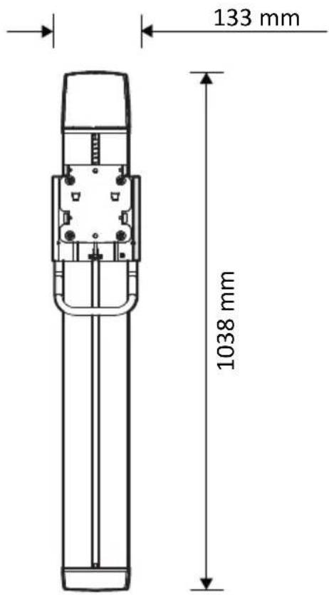
Preparation (see Fig. B, C):
NOTICE
The guide carriage may jam!
- Only mount the height adjustment vertically on a flat wall surface.
-
Protect the height adjustment from drilling dust.
-
Select a wall with a sturdy, weight-bearing surface.
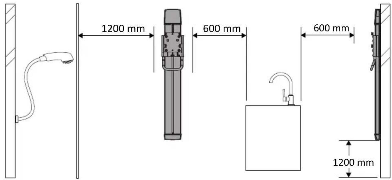
- Observe dimensions, installation height and minimum distances (see Fig. B, C).
- Have suitable fastening material to hand for installation on the wall.
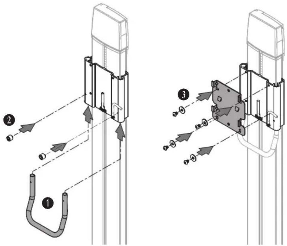
Installing the handle and the mounting plate (see Fig. D):
- Insert handle into guide carriage.
- Fix handle with 2 grub screws M4x5.
- Fix the mounting plate to the guide carriage with 4 round head screws M6x8 and 4 washers 6.4x18x1.5.
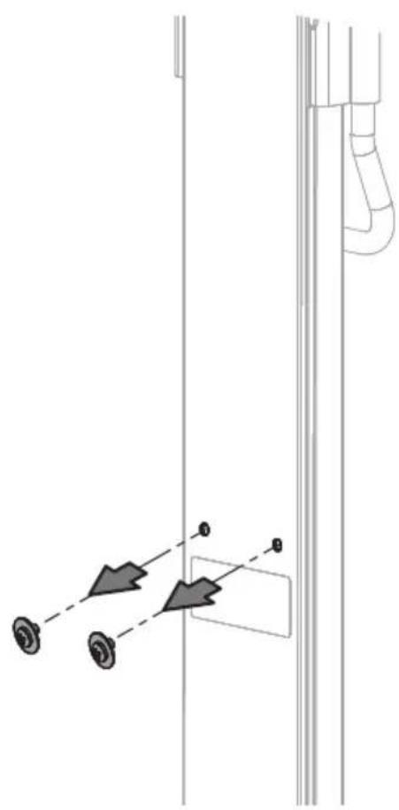
Fastening the height adjustment to the wall (see Fig. E, F):
- Hold height adjustment against the wall and mark all 3 drill holes.
- Drill the holes. Drilling diameter 8 mm, drilling depth 70 mm.
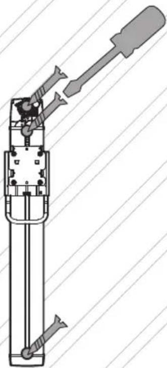
- Remove both transport locking screws on the back of the height adjustment (Fig. E).
- Fasten the height adjustment to the wall using suitable mounting material.
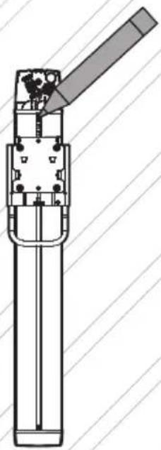
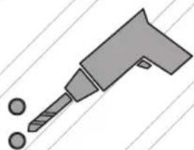
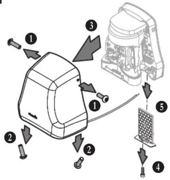
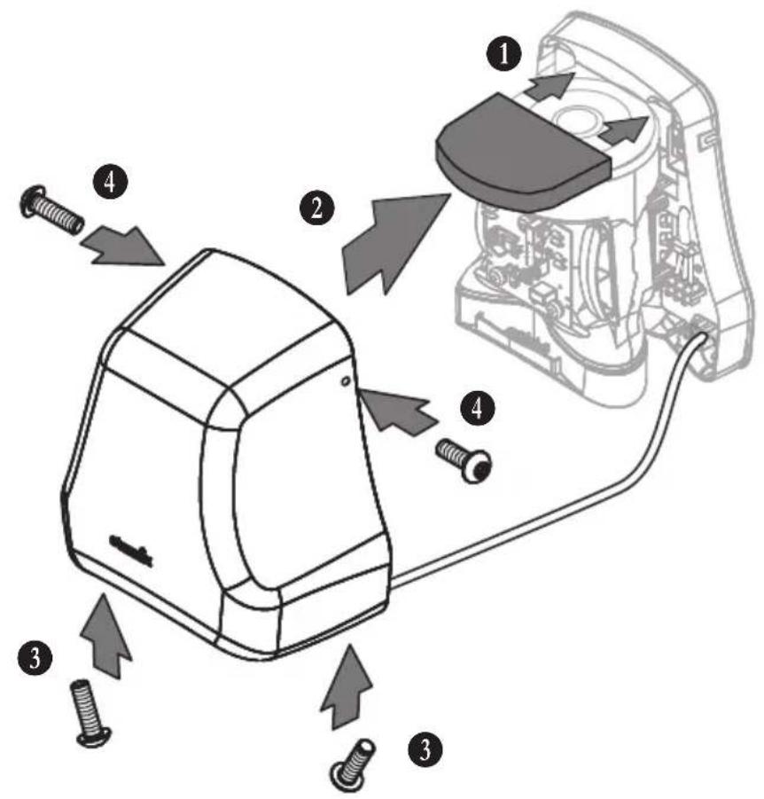
Removing the hood from the hair dryer (see Fig. G):
- Loosen upper two fastening screws of the hood.
- Loosen lower two fastening screws of the hood.
- Remove hood from the hair dryer.
- Disconnect protective earth wire (PE) of the hood from the terminal. NOTICE! Do not open the screw on the metal hood.
Fastening the hair dryer to the height adjustment (see Fig. G):

CAUTION
The device can become detached from the mounting plate!
Risk of injury caused by the device falling down.
The locking screw for the air intake grille also serves to fasten the device to the mounting plate.
If the locking screw is not properly tightened:
-
Ensure that the device cannot be accidentally pushed off of the mounting plate.
-
Unscrew the locking screw on the air intake grille on the underside of the device.
- Pull the air intake grille downwards out of the device.
- Insert the spiral cable into the cable guide on the back of the device.
- Push the air intake grille back into the device (approx. 5 cm of the air intake grille remains visible).
- Insert the device from above into the 4 lugs on the mounting plate.
- Press the device down as far as it will go.
- Place one hand on the upper side of the device to fix it, at the same time push the air intake grille completely into the hair dryer from below.
- Fasten the air intake grille and the device with the locking screw.
Connecting the device to the power supply
See Fig. H, I, J, K
Observe the following conditions for the electrical connection:
- Only connect the device to a properly installed grounded socket.
- With fixed connection: Supply line must have a switch-off device, e.g. a circuit breaker that can be switched off or a screw-in fuse.
- Connect the device to an electrical supply line with a residual current circuit breaker.
- Do not connect other loads to the electrical supply line of the device.

DANGER
Live electrical supply line and device components!
Risk of deadly electric shock in case of contact.
Before performing any work on the device:
-
Unplug power cord. With fixed connection: Switch off circuit breaker or unscrew fuse.
-
Secure against accidental switching on.
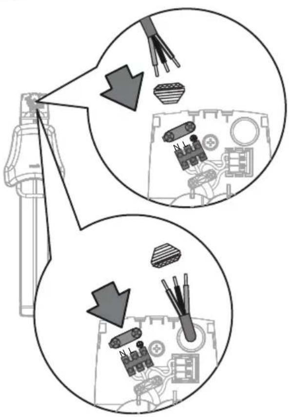
Guiding the electrical cables through the rear wall of the hair dryer housing (see Fig. H):
-
Guide the spiral cable through the opening in the rear wall of the housing.
-
Guide the protective earth wire through the opening in the rear wall of the housing.
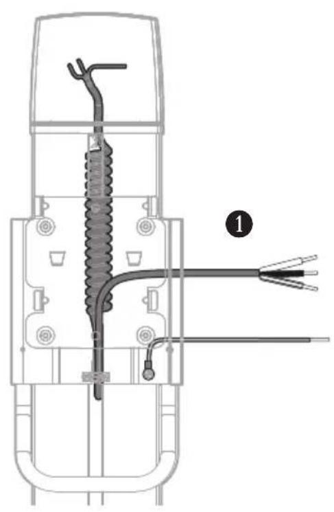
Collecting the protective earth connections in the housing of the hair dryer (see Fig. 1):
-
Establish protective earth connection between screw terminal and plug-in terminal (Fig. A, item 11). Use 70 mm protective earth wire for this (Fig. A, Item 9).
-
Plug the protective earth wire of the guide carriage into the plug-in terminal.
-
Plug the protective earth wire of the hair dryer hood into the plug-in terminal.
Connecting the spiral cable to the hair dryer (see Fig. I):
-
Connect the spiral cable to the screw terminal.
-
Insert the spiral cable together with protective earth wire of the guide carriage into the strain relief and fix in place.
Placing the hood on the hair dryer (see Fig. J):
-
Place hood on the hair dryer. NOTICE! Do not damage the protective earth wire. Ensure that the motor protection filter is correctly seated.
-
Tighten the lower two fastening screws of the hood.
-
Tighten the upper two fastening screws of the hood.
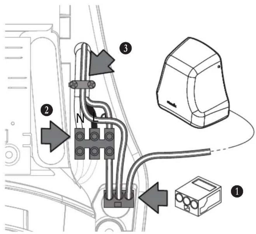
Connecting the electrical supply cable to the height adjustment (see Fig. K):
-
Depending on the desired cable routing: Break out the opening on the top of the cover cap or on the back of the profile cover.
-
Insert the grommet into the broken out opening.
-
Pass the supply cable through the grommet.
-
Connect the electrical supply cable to the screw terminal.
-
Insert the electrical supply cable into the strain relief (Fig. A, Item 16) and fix it with screws (Fig. A, Item 7).
-
Fit the cover.
-
Plug the plug into the socket, switch on the automatic fuse or screw in the fuse.
4 Initial operation
Please observe the following before initial operation
Ensure that the following requirements are met:
△ Safety distances according to DIN have been observed.
△ Protective earth wire and power supply cable are properly connected.
5 Conduct in case of emergency
In cases of fire hazard, electrical shock, mechanical damage, unusual operating conditions or misuse, proceed as follows:
- Unplug power cord. With fixed connection: Switch off circuit breaker or unscrew fuse.
- Secure against accidental switching on.
6 Troubleshooting and repairs
| Malfunction Cause Remedy | ||
| The device does not start Fuse has tripped Switch on circuit breaker or replace fuse | ||
| Spiral cable defective Have the spiral cable replaced by qualified personnel | ||
| Guide carriage stiff or makes noises | Guide rails dirty Clean and grease | |
| Guide carriage sinks The rope of the balance weight has come loose or is torn | Attach rope to balance weight or replace rope | |
Do not take any further action; contact customer service instead.
7 Maintenance

DANGER
Live electrical supply line and device components!
Risk of deadly electric shock in case of contact.
Before performing any work on the device:
-
Unplug power cord. With fixed connection: Switch off circuit breaker or unscrew fuse.
-
Secure against accidental switching on.
Regular checks
- Include height adjustment in the regular inspection of electrical appliances.
Cleaning the device
Do not clean the device with a high-pressure cleaner. Only use a damp cloth and mild cleaning agents to clean the device. Acids, acetone or solvents can damage the housing or device components.
- Clean height adjustment depending on degree of utilization and amount of dirt.
8 Disposal
Old equipment contains valuable materials which are designed for re-processing. The vacuum cleaners must not be thrown away in the normal household waste, but should be disposed of at a suitable proper collection system, e. g. via your communal disposal location.
9 Technical data
| H-C1 M | |
| Voltage V 220-240 | |
| Frequency Hz 50/60 | |
| Protection class I | |
| Height adjustability mm 600 | |
| Width mm 133 | |
| Depth mm 68 (with handle) | |
| Height mm 1038 | |
| Weight kg 7.5 | |