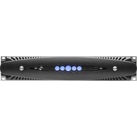
X4L - Audio Amplifier Powersoft - Free user manual and instructions
Find the device manual for free X4L Powersoft in PDF.


| Brand | Powersoft |
| Model | X4L |
| Product type | 4-channel professional audio amplifier |
| Number of channels | 4 |
| Mains power | Multi-voltage 90-464 VAC (single-phase, two-phase, three-phase) |
| Analog input connectors | 4 x female XLR (1 per channel) |
| Digital input connectors | AES3 (XLR) for channel pairs; Dante® (EtherCON) optional |
| Output connectors | 4 x Speakon (channel pairs) |
| Cooling | Forced variable speed ventilation |
| Integrated DSP | ARM Cortex A-8 processor + TI C6000 platform |
| Network | Ethernet (EtherCON), built-in Wi-Fi |
| Control software | ArmoníaPlus™ (PC) and mobile web interface |
| Main functions | Matrix routing, full equalization, delay, limiting, muting, automatic input backup |
| Warranty | 48 months parts and labor |
| Maintenance and cleaning | Clean front ventilation filter with dry cloth or compressed air |
| Safety | Automatic ground lift, overheat protection, safety cutoff |
| Spare parts and repairability | Repair at authorized center; RMA number required for return |
Frequently Asked Questions - X4L Powersoft
User questions about X4L Powersoft
0 question about this device. Answer the ones you know or ask your own.
Ask a new question about this device
Download the instructions for your Audio Amplifier in PDF format for free! Find your manual X4L - Powersoft and take your electronic device back in hand. On this page are published all the documents necessary for the use of your device. X4L by Powersoft.
USER MANUAL X4L Powersoft
natural_image
Technical line drawing of a mechanical component with symmetrical slots and mounting holes (no text or symbols)X4L

natural_image
Technical line drawing of a mechanical component with symmetrical slots and mounting holes (no text or symbols)X4

natural_image
Top-down schematic of a mechanical component with symmetrical slots and mounting holes (no text or symbols)powersoft_XSeries_qguide_mul
Data are subject to change without notice.
For latest update please refer to the English
online version available on www.powersoft-audio.com.
Regulatory information 15
Appendix: X Series Mains Wiring Option 97
Table of contents Table des matières
Important safety instructions 16
1. X Series 17
2:1.Welcome 17
2:2.Unpacking & checking for shipping damage 17
2:3.Disposal of the packaging material 17
2:4.List of image panels 17
2. Installation 18
3:1.Location 18
3:2.Cooling 18
3:3.Cleaning 18
3:4.AC mains supply 18
3:4.1. Three-phase electric power 19
3:4.2.Two-phase electric power 19
3:4.3.Single-phase electric power 19
3:5.Precautions regarding installation 19
3:6.Switch on 20
3:7.Switch off 20
3:8.Mute 20
3:9.Wi-Fi switch 20
5:1.Signal grounding 21
5:2.Analog audio input connections 21
5:3.Digital audio input connections 21
5:4.Output connections 21
5:5.Ethernet connections 21
- Software update 22
6. LED chart 22
7. Networking 23
8:1.IP addressing 23
8:1.1.IP Addressing troubleshooting 23
8:2.Dante™ networking 23
8:2.1.Redundant network configuration 23
8. ArmoníaPlus 24
9:1.Signal routing and DSP architecture 24
9:2.Purposed workflow 24
9.Warranty and assistance 25
10:1.Warranty 25
10:1.1.Product warranty 25
10:1.2. Return of Goods 25
10:1.3. Repair or replacement 25
10:1.4. Cost and responsibility of transport 25
10:2.Assistance 25
natural_image
Technical line drawing of a mechanical component with symmetrical cutouts and mounting holes (no text or symbols)X4L - X8
B


natural_image
Technical line drawing of a mechanical component with mounting holes and a base (no text or symbols)C
D
E
English
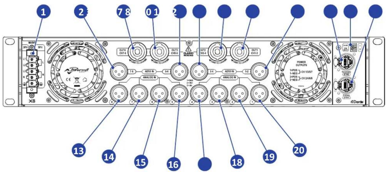
X8 Rear panel
-
AC mains Phoenix connector
-
Input: channels 7 & 8 AES XLR
-
Output: channels 7 & 8 speakON
-
Output: channels 5 & 6 speakON
-
Input: channels 5 & 6 AES XLR
-
Input: channels 3 & 4 AES XLR
-
Output: channels 3 & 4 speakON
-
Output: channels 1 & 2 speakON
-
Input: channels 1 & 2 AES XLR
-
Ethernet: etherCON secondary port
-
Remote ON/OFF Phoenix connector
-
Ethernet: etherCON primary network
-
Input: channel 8 analog XLR
-
Input: channel 7 analog XLR
-
Input: channel 6 analog XLR
-
Input: channel 5 analog XLR
-
Input: channel 4 analog XLR
-
Input: channel 3 analog XLR
-
Input: channel 2 analog XLR
-
Input: channel 1 analog XLR
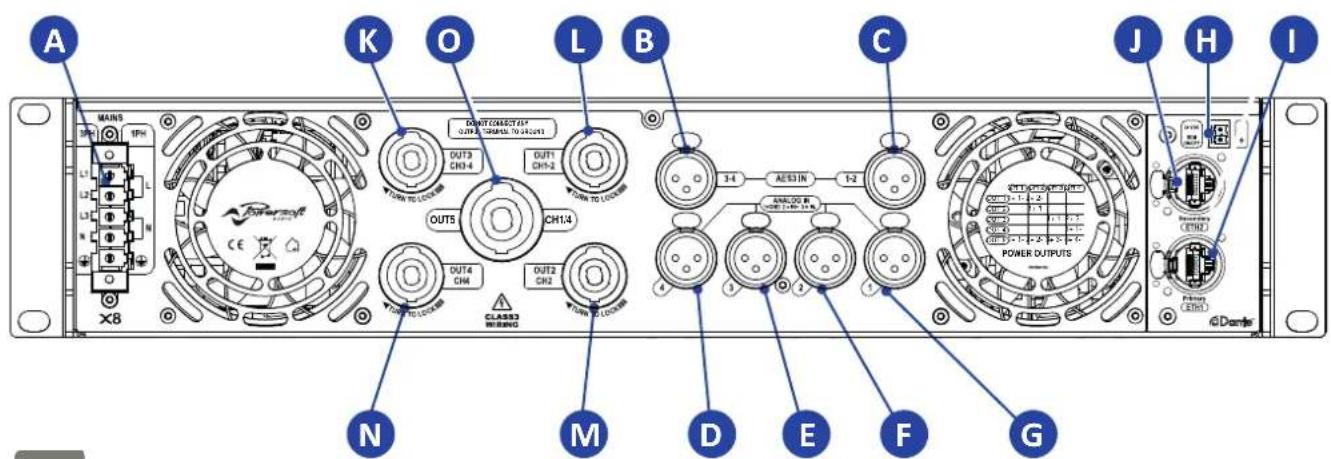
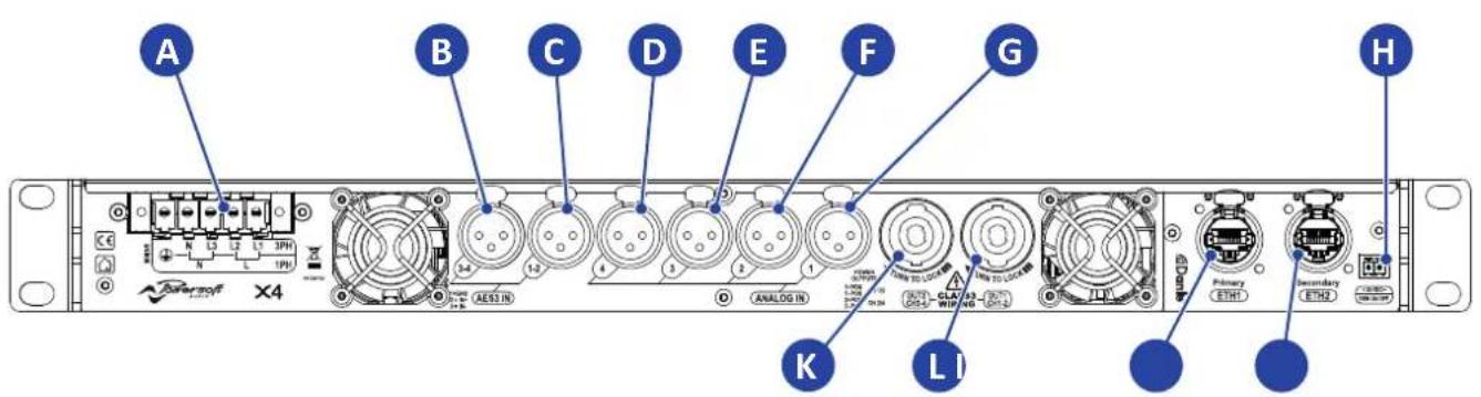
X4-X4L Rear panel
A. AC mains Phoenix connector
B. Input: channels 3 & 4 AES XLR
C. Input: channels 1 & 2 AES XLR
D. Input: channel 4 analog XLR
E. Input: channel 3 analog XLR
F. Input: channel 2 analog XLR
G. Input: channel 1 analog XLR
H. Remote ON/OFF Phoenix connector
I. Ethernet: etherCON secondary port
J. Ethernet: etherCON primary port
K. Output: channels 3 & 4 speakON
L. Output: channels 1 & 2 speakON
M. Output: channel 2 speakON
N. Output: channel 4 speakON
O. Output: channels 1/4 speakON
Française
Panneau arrière X8
H. Conector Phoenix ON/OFF Remoto
Ethernet: Puerto Secundario etherCON
J. Ethernet: Puerto Primario etherCON
A. Conector Phoenix AC principal
B. Entrada: canais 3 & 4 AES XLR
C. Entrada: canais 1 & 2 AES XLR
H. Conector Phoenix remoto ON/OFF
-
Wi-Fi on/off switch
-
USB port
-
CH1 Status LED and MUTE
-
CH2 Status LED and MUTE
-
CH3 Status LED and MUTE
-
CH4 Status LED and MUTE
-
Main on/off switch, status LED and MUTE ALL
-
CH5 Status LED and MUTE
-
CH6 Status LED and MUTE
-
CH7 Status LED and MUTE
-
CH8 Status LED and MUTE
-
Armonía callback
X4 - X4L Front panel
A. Wi-Fi on/off switch
B. USB port
C. CH1 Status LED and MUTE
D. CH2 Status LED and MUTE
E. Main on/off switch, status LED and MUTE ALL
F. CH3 Status LED and MUTE
G. CH4 Status LED and MUTE
H. Armonía callback
Español
Panneau avant X8
flowchart
graph LR
    A["output stage A"] --> B["A"]
    B --> C["1+ CHA + 1- CHA -"]
    D["output stage B"] --> E["B"]
    E --> F["2+ CHB + 2- CHB -"]
    G["output stage C"] --> H["C"]
    H --> I["1+ CHC + 1- CHC -"]
    J["output stage D"] --> K["D"]
    K --> L["2+ CHD + 2- CHD -"]
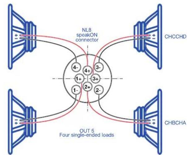
flowchart
graph TD
    A["CHCCHD"] --> B["NL8 speakON connector"]
    B --> C["OUT 5 Four single-ended loads"]
    C --> D["CHBCHA"]
    D --> E["Output Single-Ended Load"]
    style A fill:#f9f,stroke:#333
    style B fill:#ccf,stroke:#333
    style C fill:#cfc,stroke:#333
    style D fill:#fcc,stroke:#333
    style E fill:#ffc,stroke:#333
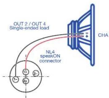
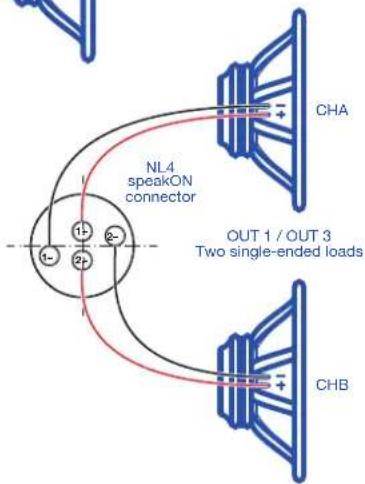
L M
N
0
natural_image
Technical line drawing of a mechanical component with multiple screw holes and mounting brackets (no text or symbols)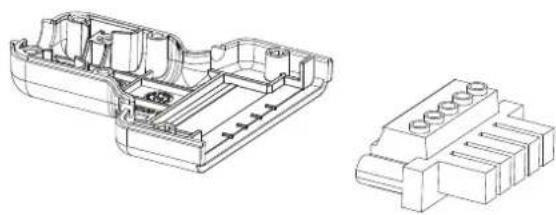
natural_image
Technical line drawing of a mechanical housing component with internal brackets and mounting holes (no text or symbols)
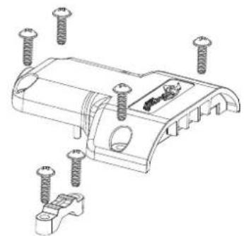
Once properly wired, insert and lock the flying connector into the shell provided by Powersoft.


Regulatory information
FCC COMPLIANCE NOTICE
This device complies with part 15 of the FCC rules. Operation is subject to the following two conditions: (1) This device may not cause harmful interference, and (2) this device must accept any interference received, including interference that may cause undesired operation.
CAUTION: Changes or modifications not expressly approved by the party responsible for compliance could void the user's authority to operate the equipment.
NOTE: This equipment has been tested and found to comply with the limits for a Class A digital device, pursuant to part 15 of the FCC Rules. These limits are designed to provide reasonable protection against harmful interference in a residential installation. This equipment generates, uses, and can radiate radio frequency energy and, if not installed and used in accordance with the instruction manual, may cause harmful interference to radio communications. However, there is no guarantee that interference will not occur in a particular installation. If this equipment does cause harmful interference to radio or television reception, which can be determined by turning the equipment off and on, the user is encouraged to try to correct the interference by one or more of the following measures:
▶ Reorient or relocate the receiving antenna.
▶ Increase the separation between the equipment and receiver.
▶ Connect the equipment into an outlet on a circuit different from that to which the receiver is connected.
Consult the dealer or an experienced radio/TV technician for help.
WEEE DIRECTIVE
If the time arises to throw away your product, please recycle all the components possible.

This symbol indicates that when the end-user wishes to discard this product, it must be sent to separate collection facilities for recovery and recycling. By separating this product from other household-type waste, the volume of waste sent to incinerators or land-fills will be reduced and natural resources will thus be conserved.
The Waste Electrical and Electronic Equipment Directive (WEEE Directive) aims to minimise the impact of electrical and electronic goods on the environment. Powersoft S.p.A. comply with the Directive 2002/96/EC and 2003/108/EC of the European Parliament on waste electrical finance the cost of treatment and recovery of electronic equipment (WEEE) in order to reduce the amount of WEEE that is being disposed of in land-fill site.
All of our products are marked with the WEEE symbol; this indicates that this product must NOT be disposed of with other waste. Instead it is the user's responsibility to dispose of their waste electrical and electronic equipment by handing it over to an approved reprocessor, or by returning it to Powesoft S.p.A. for reprocessing. For more information about where you can send your waste equipment for recycling, please contact Powesoft S.p.a. or one of your local distributors.
EC DECLARATION OF CONFORMITY
Manufacturer:
Powersoft S.p.A.
via E. Conti 5
50018 Scandicci (Fi)
Italy

We declare that under our sole responsibility the products:
Model Names: X8, X4, X4L
Intended use: Professional Audio Amplifier
Are in conformity with the provisions of the following EC Directives, including all amendments, and with national legislation implementing these directives:
▶ 2006/95/EC Low Voltage Directive
2004/108/EC Electromagnetic Compatibility Directive
2002/95/CE RoHs Directive
The following armonized standards are applied:
EN 55103-1
▷ EN 61000-3-2
EN 61000-3-3
EN 55103-2
EN 61000-4-2
EN 61000-4-3
EN 61000-4-4
EN 61000-4-5
EN 61000-4-6
▷ EN 61000-4-11
EN 60065
Scandicci,
July 2014

Luca Lastrucci
Managing Director
For compliance questions only: compliance@powersoft.it
Important safety instructions
EXPLANATIONS OF GRAPHICAL SYMBOLS

The triangle with the lightning bolt is used to alert the user to the risk of electric shock.

The triangle with the exclamation point is used to alert the user to important operating or maintenance instructions.

The CE-mark indicates the compliance with the low voltage and electromagnetic compatibility.

Symbol for earth/ground connection.

Symbol indicating that the equipment is for indoor use only.

Symbol for conformity with Directive 2002/96/EC and Directive 2003/108/EC of the European Parliament on waste electrical and electronic equipment (WEEE).

Do not use the unit at altitudes above 2000 m.

Do not use the unit in tropical environment.

WARNING: TO REDUCE THE RISK OF ELECTRIC SHOCK, DO NOT ATTEMPT TO OPEN ANY PART OF THE UNIT. NO USER-SERVICEABLE PARTS INSIDE. REFER SERVICING TO QUALIFIED SERVICE PERSONNEL.

DO NOT EXPOSE THIS EQUIPMENT TO RAIN OR MOISTURE, DRIPPING OR SPLASHING LIQUIDS. OBJECTS FILLED WITH LIQUIDS, SUCH AS VASES, SHOULD NOT BE PLACED ON THIS APPARATUS.

THE UNIT MUST BE INSTALLED IN RACK CABINETS ONLY: PLUG THE AMPLIFIER'S MAINS CONNECTIONS VIA A SECTIONING BREAKER TO A POWER DISTRIBUTION PANEL INSIDE THE RACK CABINET.

THE SECTIONING BREAKER MUST REMAIN READILY ACCESSIBLE.

WHEN THE UNIT IS INSTALLED IN A RACK CABINET, MAKE SURE THAT IT HAS SUFFICIENT SPACE ON ALL SIDES TO ALLOW FOR PROPER VENTILATION (50 CM FROM THE FRONT AND REAR VENTILATION OPENINGS).

CONNECTION TO THE MAINS SHALL BE DONE ONLY BY A ELECTROTECHNICAL SKILLED PERSON ACCORDING THE NATIONAL REQUIREMENTS OF THE COUNTRIES WHERE THE UNIT IS SOLD.

WARNING: FUSE ON NEUTRAL

CAUTION
RISK OF ELECTRICK SHOCK DO NOT OPEN

Electrical energy can perform many useful functions. This unit has been engineered and manufactured to ensure your personal safety. But IMPROPER USE CAN RESULT IN POTENTIAL ELECTRICAL SHOCK OR FIRE HAZARD.
In order not to defeat the safeguards incorporated into this product, observe the following basic rules for its installation, use and service. Please read these "Important Safeguards" carefully before use.
Important safety instructions
- Read these instructions.
- Keep these instructions.
- Heed all warnings.
- Follow all instructions.
- Do not use this equipment near water.
- Clean only with a dry cloth.
- Do not block any ventilation openings. Install in accordance with the manufacturer's instructions.
- Do not install near any heat sources such as radiators, heat registers, stoves, or other apparatus (including amplifiers) that produce heat.
- Protect the power cord from being walked on or pinched particularly at plugs, convenience receptacles, and the point where they exit from the apparatus.
- Only use attachments/accessories specified by the manufacturer.
- Use only with the cart, stand, tripod, bracket, or table speci-
fied by the manufacturer, or sold with the apparatus. When a cart is used, use caution when moving the cart/apparatus combination to avoid injury from tip-over.

- Unplug this apparatus during lightning storms or when unused for long periods of time.
- Refer all servicing to qualified service personnel. Servicing is required when the apparatus has been damaged in any way, such as power-supply cord or plug is damaged, liquid has been spilled or objects have fallen into the apparatus, the apparatus has been exposed to rain or moisture, does not operate normally, or has been dropped.
2:1.Welcome
Congratulations on buying a Powersoft X Series amplifier!
We know you are eager to use the X Series amplifier platform, but please take a moment to read this quick guide and the safety instructions. In case you have any questions, please do not hesitate to contact your dealer or Powersoft.
Powersoft X Series innovates the concept of amplifier platform: it implements a new system of channel routing, new power supply and a revolutionary full featured DSP. Powersoft X Series natively supports AES3, two redundant Dante™ by Audinate® digital streams (optional) and analog inputs, providing up to 4 different selectable input sources per channel.
For system configuration and fine tuning, ArmoníaPlus™ offers an intuitive interface, a comprehensive control over the digital audio processing and complete real-time monitoring of the system performance. The integrated Wi-Fi connection allows the Powersoft X Series to be accessed and managed via any mobile device through a user interface specifically developed for local monitoring.
Powersoft X Series raises power amplification to a new standard of quality and usability: they suit any configuration, save space and weight and offer you the legendary Powersoft efficiency with new worldwide compatible multi-phase power supplies.
2:2. Unpacking & checking for shipping damage
Your Powersoft product has been completely tested and inspected before leaving the factory. Carefully inspect the shipping package before opening it, and then immediately inspect your new product. If you find any damage, notify the shipping company or reseller immediately.
The box contains the following:
1x X Series amplifier.
1x AC mains PC 5/5-STF1-7,62 Phoenix plug
▶ 1x shell for the AC mains plug
1x quick guide
2:3.Disposal of the packaging material
The protective transport packaging has been selected from materials which are environmentally friendly for disposal and can normally be recycled.
Rather than just throwing these materials away, please ensure they are offered for recycling.
2:4.List of image panels
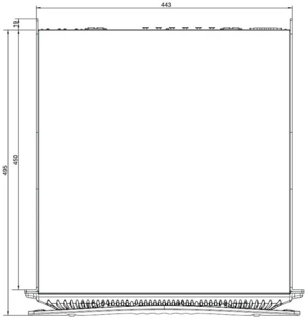
A. X8/X4L mechanical drawings: all dimensions in millimeters
B. X4 mechanical drawings: all dimensions in millimeters
C. X8 rear panel
D. X4L rear panel
E. X4 rear panel
F. X8 and X4L/X4 front panels
G. Mounting brackets and air flow direction
H. Rule for stacking amplifiers in closed racks
1. Input connector pinout
J. RJ45 Ethernet pinout
K. Loudspeakers wirings
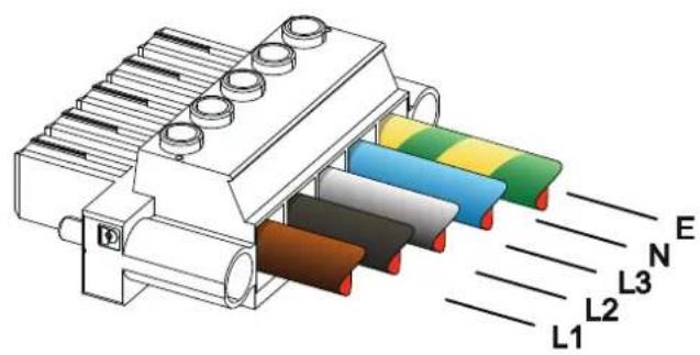
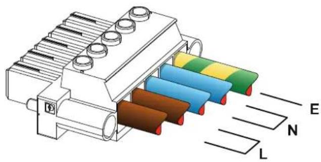
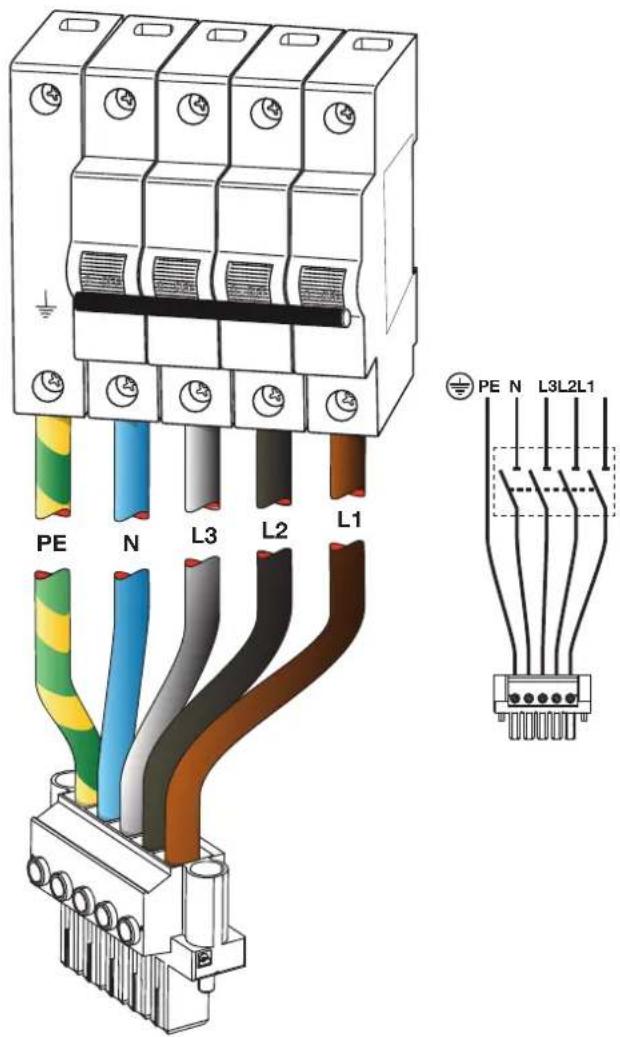
L. Three-phase electric power: AC mains plug wiring
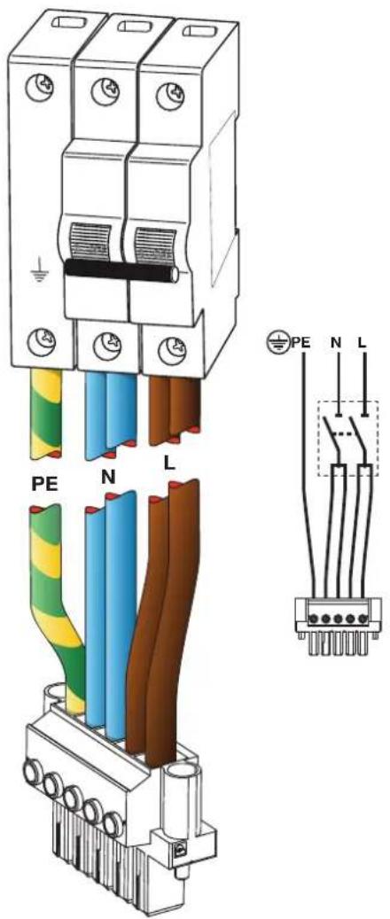
M. Single-phase electric power: AC mains plug wiring
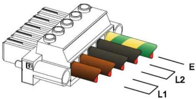
N. Two-phase electric power: AC mains plug wiring
O. AC mains plug shield
P. Regulatory information
Installation
3:1.Location
The intended use of X Series amplifiers is in a rack only. The AC mains wirings of the units must be connected to a terminal box provided with a properly breaker (refer to §3:4.Alimentazione elettrica for more details). It is not allowed to connect the X Series AC mains connection directly to the power distribution system. For North America market we recommend to use an approved UL/CSA cable (i.e. ST 600Vac 105°C 5x13AWG).
In order to limit the risk of mechanical damages, the amplifiers must be fixed to the rack using both frontal and rear mounting brackets. We recommends to use eight M6 or 12-24 UNC-2B screws for threaded holes or cage nuts.
Install this amplifier as far as possible from radio tuners and TV sets. An amplifier installed in close proximity of such equipment may experience noise or generic performance degradation. Placing and using the amplifier for long periods of time on heat generating sources will affect its performance. Avoid placing the amplifier on heat generating sources.
3:2.Cooling
Install the amplifier in a well-ventilated location: the ventilation openings must not be impeded by any item such as newspapers, tablecloths, curtains, etc; keep a distance of at least 50 cm from the front and rear ventilation openings of the amplifier.
All Powersoft amplifiers implement a forced-air cooling system to maintain low and constant operating temperatures. Drawn by the internal fans, air enters from the front panel and is forced over all components, exiting at the back of the amplifier.
The amplifier's cooling system features "intelligent" variable-speed DC fans which are controlled by the heatsink temperature sensing circuits: the fans speed will increase only when the temperature detected by the sensors rises over carefully predetermined values. This ensures that fan noise and internal dust accumulation are kept to a strict minimum.
Should however the amplifier be subject to an extreme thermal load, the fan will force a very large volume of air through the heat sink. In the extremely rare event that the amplifier should dangerously overheat, sensing circuits shut down all channels until the amplifier cools down to a safe operating temperature. Normal operation is resumed automatically without the need for user intervention.
X Series amplifiers can be stacked one on top of the other due to the efficient cooling system they are equipped with.
There is however a safety limit to be observed: in case a rack with closed back panels is used, leave one rack unit empty every four installed amplifiers to guarantee adequate air flow (see Panel G, p. 10).
3:3.Cleaning
Always use a dry cloth for cleaning the chassis and the front panel. Air filter cleaning should be scheduled according to the dust levels in the amplifier's operating environment.

Disconnect the AC mains source before attempting to clean any part of the amplifier

In order to clean the vent filters you need to remove the front cover: never attempt to open any other part of the unit.
By means of a metric hex key #6, unscrew the two screws located on the left and right sides of the front panel, (see FIG. 1) gently lift the cover and remove the filter. You may use compressed air to remove the dust from filters, or wash it with clean water: in the latter case ensure that the filter is dry before reassembly.

natural_image
Diagram of a mechanical component with two circular ports and directional arrows indicating movement or force (no text or symbols)FIG. 1: Use a #6 hex key to remove the front cover.
3:4.AC mains supply
X Series amplifiers offers worldwide AC acceptance and direct connection to any regional power line configuration. Powersoft's legendarily reliable power supply is now suitable to single-phase, two-phase or three-phase operation from 90 V_AC up to 464 V_AC without need of manual selection: true three-phase load balancing is directly achievable by the unit without any complex load assignment in the power distribution system design.
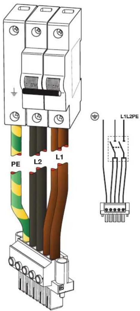
AC mains connection is provided by means of the euroblock Phoenix PC 5/5-STF1-7,62 flying plug (Phoenix product ID 1777862). Proper assembly of the AC mains conductors to the flying plug must respect the power line configuration.
Take care to connect any and all the five contacts of the flying plug to the power cords according to the configuration showed in Panel K, L, M at p. 13 and p. 14. In order to guarantee the proper connection we recommend to use an approved UL/CSA cable (i.e. ST 600Vac 105°C 5x13AWG).

This device must be powered exclusively by earth connected mains sockets in electrical works compliant to the IEC 364 or similar rules.

Since the main power switch on this unit does not provide a complete insulation of the equipment from the main power, you must disconnect the main power source to turn off all power.

Provide a sectioning breaker between the mains connections and the amplifier.

The proper device to use depends on mains configuration; for X8 Powersoft suggests:
single-phase AC (P+N+E): 32 A rating, C or D curve, 10 kA;
three-phase AC (3P+N+E): 4 x 16 A rating, C or D curve, 10 kA.
For X4 Powersoft suggests:
single-phase AC (P+N+E): 16 A rating, C or D curve, 10 kA;
three-phase AC (3P+N+E): 4 x 10 A rating, C or D curve, 10 kA.
NOTE: The pictures and instructions about AC wiring refer to the European CENELEC standards April 2004 (IEC 60446) color code for conductor identification (see TAB. 1).
| Conductor Color | ||
| Neutral or mid-point conductor N blue | ||
| AC phase conductors | L1 brown | |
| L2 black | ||
| L3 grey | ||
| Protective conductor (earth) E | green/yellow | |
TAB. 1: Color code for conductor identification.

AC mains connections must be performed only by professional or qualified personnel according to local electrical authoritie guidelines.

3:4.1. Three-phase electric power
Each single conductor must be secured to the PC 5/5-STF1-7,62 flying plug as shown in Panel K, p. 13. In some instances neutral connection may lack: on three-phase systems neutral connection is not even necessary given the capability of the X Series to work in delta connection.
3:4.2. Two-phase electric power
Balanced two-phase AC mains in the configurations 2P+E without neutral must be secured to the PC 5/5-STF1-7,62 flying plug as shown in Panel M, p. 14. Take care to double the phase wires at the connecting terminals of the sectioning breaker in order to guarantee the proper conduction gauge.
3:4.3. Single-phase electric power
P+N+E, unbalanced single-phase with neutral is the usual configuration for signle-phase AC mains; wiring must be configured as shown in Panel L, p. 13. Take care to double the phase and neutral wires at the connecting terminals of the sectioning breaker in order to guarantee the proper conduction gauge.
3:5.Precautions regarding installation
WARNING: TO PREVENT FIRE OR ELECTRIC SHOCK
④ This device must be powered exclusively by earth connected mains sockets in electrical networks compliant to the IEC 364 or similar rules.
④ Install the unit into rack cabinet only.
④ A sectioning breaker between the mains connections and the amplifier must be installed inside the rack cabinet.
④ Take care to properly lock each power cord wire to the flying connector Phoenix PC 5/5-STF1-7,62.
④ Once properly wired, insert and lock the flying connector into the shell provided by Powersoft.
④ Lock the flying connector to the amplifier inlet.
④ Before powering this amplifier, verify that the correct voltage rating is being used.
④ Verify that your mains connection is capable of satisfying the power ratings of the device.
④ Do not use this amplifier if the electrical power cord is frayed or broken.
④ Output terminals are hazardous: wiring connection to these terminals require installation by an instructed person and the use of ready-made leads.
④ Take care to lock the output terminal before switching the device on.
④ To avoid electrical shock, do not touch any exposed speaker wiring while the amplifier is operating.
④ Do not spill water or other liquids into or on the amplifier.
④ No naked flame sources such as lighted candles should be placed on the amplifier.
④ Do not remove the cover. Failing to do so will expose you to potentially dangerous voltage.
④ The manufacturer cannot be held responsible for damages caused to persons, things or data due to an improper or missing ground connection.
④ Contact the authorized service center for ordinary and extraordinary maintenance.
It is absolutely necessary to verify these fundamental requirement of safety and, in case of doubt, require an accurate check by qualified personnel.
3:6.Switch on
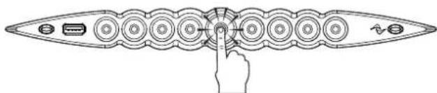
As soon as you connect the amplifier to the power grid, the amplifier's power supply will start supplying power to the auxiliary systems. The border of the central button starts blinking white: the amplifier is in standby mode.
A pressure on the central button will wake up the amplifier.

flowchart
graph TD
    A["Node"] --> B["Node"]
    B --> C["Node"]
    C --> D["Node"]
    D --> E["Node"]
    E --> F["Node"]
    F --> G["Node"]
    G --> H["Node"]
    H --> I["Node"]
    I --> J["Node"]
    J --> K["Node"]
    K --> L["Node"]
    L --> M["Node"]
    M --> N["Node"]
    N --> O["Node"]
    O --> P["Node"]
    P --> Q["Node"]
    Q --> R["Node"]
    R --> S["Node"]
    S --> T["Node"]
    T --> U["Node"]
    U --> V["Node"]
    V --> W["Node"]
    W --> X["Node"]
    X --> Y["Node"]
3:7.Switch off
Keep pressed the central button for 3 seconds to switch the amplifier off. The amplifier platform passes to the standby mode and the border of the central button blinks white.
The amplifier platform turns completely off only when the mains connector is unplugged.
3:8.Mute
A short pressure on the central button toggles MUTE/ UNMUTE to all active channels: any previously muted channel will remain in mute status.
All other circular buttons (except the central one) toggle the MUTE/UNMUTE to the specified output channel.

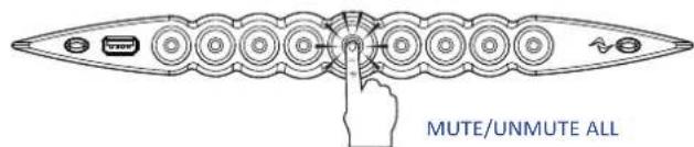
NOTE: Please note that when the amplifier platform is linked and controlled by ArmoníaPlus™ all MUTE switches are locally disabled.
3:9.Wi-Fi switch
Press the leftmost button: the button will light up and the system will establish a new local Wi-Fi network whose SSID is in the form: Powersoft-MODELNAME-SERIAL (e.g. Powersoft-X8-70133) and default password: 0123456789.
Press again the leftmost button to switch the Wi-Fi off.
In order to identify the unit into the Armonía Workspace, push on the rightmost button. On the other hand, if you click on Un/ Blink from the contextual menu of the amplifier into the Armonía Workspace, all the front LEDs of the amplifier will blink for a while.
Wi-Fi
4
The factory default frequency setting on an X Series amplifier is 5GHz, but it's possible to change it to 2.4 GHz via ArmoníaPlus. Follow this procedure to activate the Wi-Fi connection and remotely access your Powersoft X Series amplifier platform.
- Switch on the amplifier by holding down the central button on the front panel;
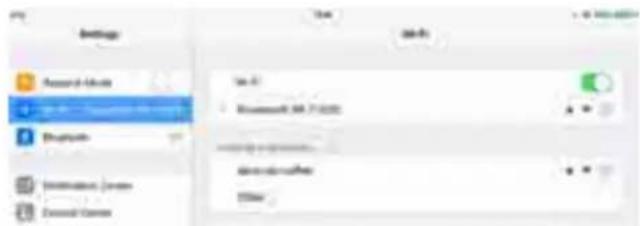
- Press the leftmost button in the front panel: the button will light up and the system will establish a new local Wi-Fi network whose SSID is in the form:
Powersoft-MODELNAME-SERIAL (e.g. Powersoft-X8-71520)
- Access your mobile device and edit the Wi-Fi configuration;
- Hang the Wi-Fi network with the right SSID;
- Insert the following default Wi-Fi encryption password:
0123456789
- Open the web browser and type the following IP address in the address bar:
192.168.0.1
- The system will push the user interface to the browser: now you can start managing your X Series amplifier platform.

-
For simple recall and operation with the interface, we suggest to bookmark the page on the home screen of your mobile device; for example, in iOS device click on the share icon and select "Add to Home Screen" when the interface has been completely loaded.
-
Remember to switch the local Wi-Fi network off when monitoring and basic setup are no more necessary: press the leftmost button in the front panel in order to switch off the Wi-Fi.
Connections
Make sure the power switch is off before attempting to make any input or output connections.
By using good quality input and speaker cables, the likelihood of erratic signal behavior is reduced to a minimum. Whether you make them or buy them, look for good quality wires, connectors and soldering techniques.
5:1.Signal grounding
There is no ground switch or terminal on the X Series amplifiers. All shield terminals of input connections are directly connected to the chassis. This means that the unit's signal grounding system is automatic. In order to limit hum and/or interference entering the signal path, use balanced input connections.
In the interests of safety, the unit MUST always operate with electrical safety earth connected to the chassis via the dedicated Protective Earth ⊕ wire.
5:2.Analog audio input connections
Analog input is provided by means of Neutrik XLR female connectors, one per channel input. Signal polarity of analog input connections is shown in Panel H, p. 12.
5:3. Digital audio input connections
Digital input is supported via AES3 (AES/EBU) and Dante™ standard protocols in Dante equipped devices.
AES3 connectors are Neutrik XLR female, one per channel pair. The AES3 connection carries a channel pair through a 110 Ω nominal impedance wire in the form of a balanced (differential) digital signal: in AES3 XLR connectors the identification of hot and cold pins is not an issue; take care to never tie pin 2 or pin 3 (balanced signals) to pin 1 (ground). Avoid the use of microphone cables in AES connections: impedance mismatch can result in signal reflections and jitter, causing bit errors at the receiver.
In Dante equipped devices, Dante connectivity is supported via two Neutrik etherCON ports located on the rightmost side of the X8 and X4 rear panels. Fast Ethernet (IEEE 802.3u, 100 Mbit/s) and Gigabit Ethernet (IEEE 802.3ab, 1 Gbit/s) network protocols are supported; Cat5e or Cat6 standard UTP twisted pair cables shall be used for connections up to 100 meters (328 ft).
Ethernet cabling must comply to TIA/EIA-568-B and adopt the T568B scheme pinout, as shown in Panel I, p. 12.
5:4.Output connections

CLASS 3 WIRING
CLASS3 Output terminals are hazardous: wiring connection to WIRING these terminals require installation by an instructed person and the use of ready made leads. Take care to secure the output terminals before switching the device on.
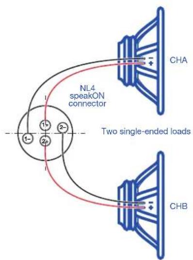
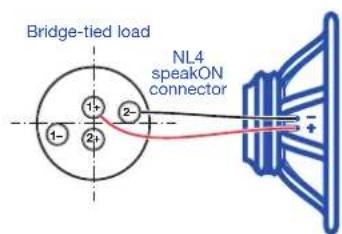
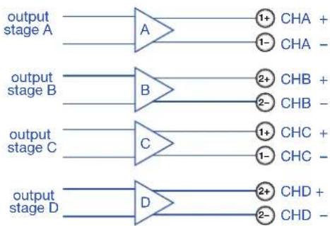
Single-ended and bridge-tied loudspeakers connection are supported as shown in Panel J, p. 12.
5:5.Ethernet connections
X Series amplifier platforms can be remotely controlled via an Ethernet connection through a personal computer and Powersoft ArmoníaPlus software.
Powersoft recommends the use of Ethernet Cat5 straight through - patch - cables with pin/pair assignments TIA/EIA-568-B, i.e. T568B, as shown in Panel I, p. 12.
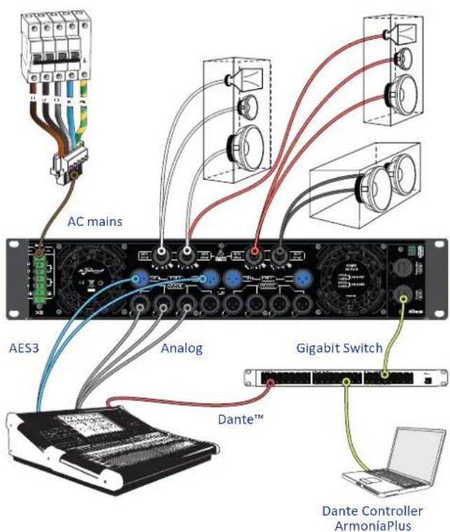
FIG. 2: Example of X8 connections.
Software update LED chart
6
7
Powersoft X Series amplifier platforms embed a complete digital audio signal management system based on ARM Cortex A-8 processor and TI C6000 DSP platform. This impressive onboard computing capacity is driven by a dedicated software environment.
Updated releases of the X Series software are available on the Armonía forum (https://armonia.powersoft.it/).
The package contains the software update file whose name is in the form:
update-version#-model.bin
(e.g. update-v1.5.0.6-x4.bin); in order to update the software of your X Series amplifier platform you must store the software update file into a USB key and follow these instructions:
- Switch the amplifier on and wait for the completion of the boot sequence.
natural_image
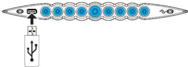
Diagram of a mechanical or electrical component with circular elements and a pointer, no text or symbols present- Plug the USB key with the software update file to the USB port in the front panel of the amplifier.
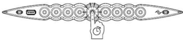
- Keep pressed the rightmost pushbutton (Armonía callback) until the second beep is emitted and the LEDs start blinking.
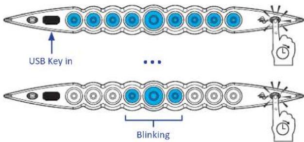
- Wait until the amplifier restarts and all front LEDs turn solid blue.
All circular back illuminated buttons provide status information. The CENTER of each channel button provides status information about the OUTPUT signal.
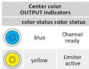
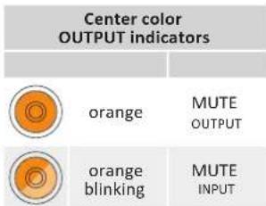
The RING of each channel button provides status information about the INPUT signal.
| Ring color INPUT indicators | |
| color status | |
| white blinking (center blue) | Input signal presence |
| red Input signal clipping | |
Channel fault and Armonía callback are associated to the following LED signals.
| color status | ||
| red blinking (center and ring) | Channel fault | |
| blinking / all channels (center and ring) | Unit answering to Armonía callback | |
The central button light on when the system is in standby mode or in case of failure in the power supply unit:
| Ring color CENTRAL button | |
| color status | |
| white pulsing (all LEDs off) | System powered Standby mode |
| red pulsing (normal operating) | fan fault detected (output stage side fan) |
| Center color CENTRAL button | |
| color status | |
| red blinking | power supply or PSU fan fault detected |
| yellow blinking | power supply temperature protection active |
X Series amplifier platforms support linear daisy-chain, star and loop network topologies; in a daisy-chained network the PC with ArmoníaPlus must always be at one end of the chain.
Be aware that daisy-chaining does not guarantee reliability in production environment, since any fault may yield to network sectioning and loss of system control.
When efficiency and reliability are paramount, a redundant network topology is advisable. In order to exploit the Dante features, only star and open daisy-chain network topology are allowed.
8:1.IP addressing
Factory default network settings are DHCP/AutoIP, in order for the amplifier platform to self-configure when connected to an existing LAN or PC. Fixed IP policy can also be adopted and configured through ArmoníaPlus.
If a DHCP server is not active within the network, the amplifier platform initiates a stateless address auto-configuration (i.e. Zero-configuration networking methodology – Zeroconf): it self assigns a local numeric network address (of the type 169.254.x.y – 172.31.*.* for the secondary network if present – with a subnet mask 255.255.0.0) and automatically distributes and resolves the hostnames of networked devices. For setting a static IP address, please refer to the ArmoníaPlus user guide.
8:1.1. IP Addressing troubleshooting
When connecting the X Series to a network environment it may happen that ArmoníaPlus does not discover or import the amplifier.
Usually this is a problem of IP addressing: both Armonia and the X Series must belong to the same subnet. If a DHCP server is present on the network and a X Series amplifier platform is in AUTO IP, networking may become unstable.
As a rule of thumb, turn the DHCP server on before connecting the amplifiers.
IP addressing of a X Series amplifier is established during the bootstrap: when the X Series amplifier platform discovers a DHCP server on the network during the startup, it negotiates the networking parameters. If the X Series amplifier platform does not reveal a DHCP server on the network during the startup, it set itself in AUTO IP mode.
8:2.Dante™ networking
The Dante equipped models of the X Series amplifier platforms support Dante redundant networking via the two etherCON ports on the rear panel:
▶ Primary/ETH1 is the Primary network port;
▶ Secondary/ETH2 is the Secondary network port.
Dante connectivity is always supported on the Primary/ETH1 Gigabit Ethernet port; the Secondary/ETH2 Gigabit Ethernet port offers continuity of operation when a parallel redundant network is established.
In order to implement a Dante network, a computer running Dante Controller have to be used. Dante Controller is a software application that manages devices on the network. X series amplifier platforms are automatically discovered and displayed in Dante Controller with the default identifier MODELNAME-SERIAL (e.g. X8-71520).
Dante networks will almost always require at least one network switch. Redundant infrastructures may require multiple switches. For maximum reliability, network switch shall:
④ be Rated for Gigabit Ethernet;
④ be Non-blocking;
④ have Quality of Service (QoS) with at least four queues;
④ have Diffserv (DSCP) QoS with strict priority;
④ have EEE (Energy efficient ethernet) switched off.
For detailed information on setting up a switch, please refer to the manufacturer's documentation.
8:2.1. Redundant network configuration
Dante Redundancy can be set-up and used between any supporting Dante-enabled audio equipment: it works by using two completely independent and separate networks, the Primary Network and the Secondary Network.
To setup and use Dante Redundancy, connect the X Series amplifier platform and other redundant Dante-enabled audio equipment using duplicate Gigabit switches and Ethernet cables. Connect your computer running Dante Virtual Soundcard and Dante Controller, and other non-redundant Dante-enabled audio equipment to the Primary Network.
The primary and secondary networks MUST NOT be interconnected at any point. Make sure any computer is set to automatically configure its IP address.
ArmoníaPlus
ArmoníaPlus is the default configuring interface that allows system setting and customization of the X Series amplifier platforms.
ArmoníaPlus can be installed on a PC running Windows (XP SP3 and higher). ArmoníaPlus is available for free from the Armonía website, where a startup guide and in depth tutorials are also provided:
https://armonia.powersoft.it/
X Series amplifier platforms can be connected to a PC running ArmoníaPlus through a Fast Ethernet connection. In order to start remote operation, the amplifier must be added into the ArmoníaPlus Workspace. Add the amplifier by selecting the family and model.
The X Series amplifier must then be matched by clicking on the Match section of the workspace, and then by clicking on "Discovery" to reveal any device which is available on the network.
The callback button – located rightmost on the front panel of the amplifier – allows you to highlight the amplifier in the discovery panel.
FIG. 3: ArmoníaPlus.
9:1. Signal routing and DSP architecture
Signal processing on Powersoft X Series amplifier platforms accomplishes multiple functions that affect the audio signal before power amplification. The main adjustments include gain, polarity, delay, limiting and signal equalization; some processing are related only to particular stages, such as limiting and damping control that are implemented on the output section only, or input priority assignment available in the input section.
The processing architecture is composed of six sections:
Input source selection. The input section allows you to manage input gain and delay of analog and digital sources, in order to compensate transmission latency and levels. Furthermore, the X Series implements a backup policy aimed to improve reliability against signal fault. By assigning a bus priority to the four different input sources – analog,
AES3 and two Dante streams – per channel, the system is able to automatically switch to a reliable input connection in case of any signal fault.
▶ Matrix. The innovative routing engine of X Series allows any input to be routed to any output. The Matrix implements a non-Boolean routing architecture allowing free channel assignment and level adjustment.
▶ Advanced processing. This allows you to optimize levels and shape the sound of the input signals. Gain and polarity adjustment, asymmetric raised-cosine full parametric filters, delay and mute are available on each channel routed to the speaker section.
▶ Speaker equalization. Designed to manage the configuration presets for multi-way systems, it implements FIR and IIR full parametric filters.
▶ Speaker routing. Once properly grouped, the output channels are presented to the matrix as speakers – a single row representing a speaker (actually group of ways) – allowing a high grade of granularity in signal processing.
▶ Output processing. This allows fine-tuning of output signals, aiming to optimize power delivering and loudspeaker performance. It provides gain and polarity adjustment, IIR and FIR full parametric filters, delay, mute, limiting and damping control on each output channel.
9:2.Purposed workflow
Once the loudspeaker layout has been defined, we suggest a bottom-up configuration procedure that starts from the configuration of the transducers layout and raises toward the input selection and the definition of the backup policy.
Shortly, the main steps to follow are:
- Load the loudspeaker presets or manually configure the loudspeaker layout (grouping output channels, crossovering, limiting, speaker processing, etc.).
- Define the routing path and the levels of the signals from the input channels to the active output channels (matrix).
- Select the signal source from the input connections and define the backup policy (input source selection).
Warranty and assistance
10:1.Warranty
10:1.1.Product warranty
Powersoft guarantees its manufactured products to be free from defective components and factory workmanship for a period of 48 (forty eight) months, starting from the date of purchase printed on Powersoft's (or any of its Authorized Dealer's) invoice to the end customer. All warranty repairs and retrofits must be performed at Powersoft facilities or at an Authorized Service Center at no cost for the purchaser. Warranty exclusion: Powersoft's warranty does not cover product malfunctioning or failure caused by: misuse, abuse, repair work or alterations performed by non-authorized personnel, incorrect connections, exposure to harsh weather conditions, mechanical damages (including shipping accidents), and normal wear and tear. Powersoft will perform warranty services provided that the product is not damaged during transportation.
10:1.2. Return of Goods
Goods can be returned to Powersoft only after they have been granted a Return Merchandise Authorization (RMA) number to be attached to the external packaging. Powersoft (or its Authorized Service Center) has the right to refuse any returned good without a RMA number.
10:1.3. Repair or replacement
Powersoft reserves the right to repair or replace any defective goods covered by product warranty at its sole discretion and as it deems best.
10:1.4. Cost and responsibility of transport
The purchaser (or end user/customer) is solely responsible for all transportation costs and risks associated with sending warranty covered goods to Powersoft or its Authorized Service Center. Powersoft will assume full responsibility and cover all costs incurred to send the goods back to the purchaser (or end user/customer).
10:2.Assistance
There are no user-serviceable parts in your amplifier. Refer servicing to qualified technical personnel. In addition to having an in-house service department, Powersoft supports a network of authorized service centers. If your amplifier needs repair, contact your Powersoft dealer (or distributor). You can also contact the Powersoft Technical Service department to obtain the location of the nearest authorized service center.
Even though most product malfunctioning can be solved at your premises through Powersoft Customer Care or your direct knowledge, occasionally, due the nature of the failure, it might be necessary to return defective products to Powersoft for repair. In the latter case, before shipping, you are kindly asked to follow step by step the procedure described below:
Obtain the "Defect Report Form" by contacting our Customer Care Department via email: service@powersoft.it or download the "Defect Report Form" from Powersoft's website (http://www.powersoft-audio.com/en/support/service).
▶ Fill out one "Defect Report form" for each returned item (the form is an editable tab guided document) and save as your name, amp model and serial Number (for example: distributornamek10sn17345.doc) providing all required information except the RMA code/s and send it to service@powersoft.it for Powersoft approval.
In case of defect reports approved by the Powersoft Customer Service Representative you will receive an RMA authorization code (one RMA code for each returning device).
Upon receiving the RMA code you must package the unit and attach the RMA code outside the pack, protected in a waterproof transparent envelope so it is clearly visible. All returning items must be shipped to the following address:
Powersoft
50018 Scandicci (FI) Italy
In case of shipment from countries NOT belonging to the European Community make sure you have also followed the instructions described in the document available for download at the TEMPORARY EXPORTATION / IMPORTATION PROCEDURE link at http://www.powersoft-audio.com/en/support/service.
Thank you for your understanding and cooperation and continued support as we work to improve our partnership.
RISQUES D'ÉLECTROCUTION NE PAS OUVRIR

natural_image
Diagram of a device rear panel with circular components and directional arrows indicating orientation (no text or symbols)3:7.Eteindre
natural_image
Diagram of a mechanical component with circular elements and a hand pointing to a central point (no text or symbols)MODE MUET ACTIVÉ/DÉSACTIVÉ CANAL 2
natural_image
Diagram of a mechanical or electrical component with circular elements and a hand pointing to a central hub (no text or symbols)MODE MUET ACTIVÉ/DÉSACTIVÉ TOUS
https://armonia.powersoft.it/
natural_image
Interior view of a server room with multiple drive bays and indicator lights (no visible text or labels)FIG. 3: ArmoníaPlus.
50018 Scandicci (FI) Italy
natural_image
Pure mechanical component diagram without any text, numbers, or symbolssingle-phase AC (P+N+E): 16 A rating, C or D curve, 10 kA; three-phase AC (3P+N+E): 4 x 10 A rating, C or D curve, 10 kA.
natural_image
Hand cursor icon pointing at a starburst effect (no text or symbols)https://armonia.powersoft.it/
natural_image
Interior view of a server room with multiple drive bays and a central door (no visible text or labels)FIG. 3: ArmoníaPlus.
50018 Scandicci (FI) Italy
natural_image
Pure electrical circuit lines without any symbolsnatural_image
Diagram of a multi-stage electronic device with circular components and a central indicator (no text or symbols)https://armonia.powersoft.it/
natural_image
Interior view of a large electronic or industrial control room with multiple panels and equipment (no visible text or symbols)FIG. 3: ArmoníaPlus.
50018 Scandicci (FI) Italy
natural_image
Diagram of a mechanical component with two circular features and directional arrows indicating movement or force (no text or symbols)图 1: 使用内六角扳手打开前面板.
3:4. 交流电源
natural_image
Diagram of a boat's hull with circular patterns and directional arrows, no text or symbols present3:7. 关闭
https://armonia.powersoft.it/
natural_image
Interior view of a server room with multiple workstations and equipment (no visible text or labels)3: ArmoníaPlus.
50018 Scandicci (FI) Italy
natural_image
Diagram of a device panel with four circular components and two arrows pointing to the top section (no text or symbols present)natural_image
Diagram of a mechanical component with circular elements and a hand gesture (no text or symbols)3:7.Ausschalten
https://armonia.powersoft.it/
natural_image
Interior view of a server room with multiple drive bays and indicator lights (no visible text or labels)FIG. 3: ArmoníaPlus.
50018 Scandicci (FI) Italy
natural_image
Diagram of a mechanical component with two circular features and directional arrows indicating movement or force (no text or symbols)https://armonia.powersoft.it/
natural_image
Interior view of a server room with multiple drive bays and a central control unit (no visible text or labels)РИС. 3: ArmoníaPlus.
50018 Scandicci (FI) Italy
Do not use the unit in tropical environment

AVISO: PARA REDUZIR O RISCO DE CHOQUE ELÉTRICO, NÃO TENTE ABRIR QUALQUER PARTE DO EQUIPAMENTO. NÃO EXISTEM AJUSTES INTERNOS. PROCURE ASSISTÊNCIA COM O SERVIÇO AUTORIZADO.

NÃO EXPONHA ESTE EQUIPAMENTO À CHUVA OU UMIDADE, NÃO BORRIFE OU ESPIRRE LÍQUIDOS. RECIPENTES COM LÍQUIDOS, COMO VASOS, NÃO DEVEM SER COLOCADOS SOBRE ESTE APARELHO.

ESTE APARELHO DEVE SER INSTALADO APENAS EM GABINETES DE RACK: CONECTE A ALIMENTAÇÃO DO AMPLIFICADOR ATRAVÉS DE UM DISJUNTOR NO PAINEL DE DISTRIBUIÇÃO INTERNO DO RACK.

O DISJUNTOR DEVE SER DE FÁCIL ACESSO.

QUANDO ESTE APARELHO FOR INSTALADO EM UM RACK, VERIFIQUE SE HÁ ESPAÇO SUFICIENTE EM TODOS OS LADOS PARA PERMITIR A VENTILAÇÃO ADEQUADA (50 CM NAS ABERTURAS DE VENTILAÇÃO DA FRENTE E DA TRASEIRA).

A CONEXÃO DE ENERGIZAÇÃO DEVE SER FEITA POR ELETRICISTA QUALIFICADO, DE ACORDO COM AS EXIGÊNCIAS DO PAÍS EM QUE O APARELHO FOI COMERCIALIZADO.

natural_image
Diagram of a boat's hull with circular patterns and a hand pointing to the center (no text or symbols)https://armonia.powersoft.it/
natural_image
Interior view of a large industrial or warehouse space with multiple rectangular structures and no visible text or symbols.FIG. 3: ArmoníaPlus.
9:1.Roteamento de sinal e arquitetura DSP
50018 Scandicci (FI) Italy
X Series Mains Wiring Option
| CONNECTION SYSTEM | CABLE WIRING | X SERIES CONNECTOR | BREAKER CONNECTION | |
| 1 | 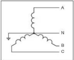 | A ®L_1 B ®L_2 C ®L_3 N ®N ® | 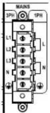 | |
| 3-Phase Wye: 4-Wire; Grounded Neutral and Contiguous Ground. | ||||
| 2 | 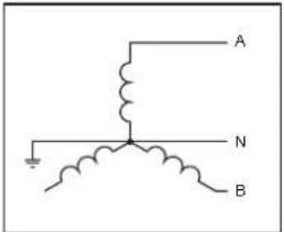 | A ®L_1//L_2 B ®L_3//N N ®n.c. ® | 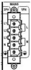 | Symbol “L1 // L2” (parallel connection) means connect the pole L1 together with the pole L2.The parallel connection must be done at the breaker output and not at the connector level.Symbol “n.c.” means not connected. |
| 2-Phase Wye: 3-Wire; Grounded Neutral and Contiguous Ground (typically called a single phase supply in North america). | ||||
| 3 | 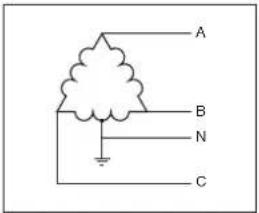 | A ®L_3 B ®L_2 C ®L_3 N ®n.c. ® | 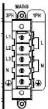 | |
| 3-Phase Delta: 4-Wire; Grounded at Midpoint pf Phase and Contiguous Ground | ||||
| 4 | 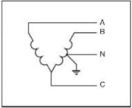 | A ®L_1//L_2 B ®L_3//N C ®n.c. N ®n.c. ® | 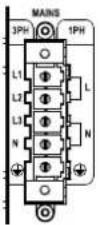 | Symbol “L1 // L2” (parallel connection) means connect the pole L1 together with the pole L2.The parallel connection must be done at the breaker output and not at the connector level.Symbol “n.c.” means not connected. |
| 3-Phase Open Delta: 4-Wire; Grounded at Midpoint pf Phase; Contiguous Ground | ||||
| 5 | 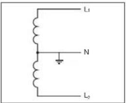 | L_1®L_1//L_2 L_2®L_3//N N ®n.c. ® | 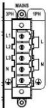 | Symbol “L1 // L2” (parallel connection) means connect the pole L1 together with the pole L2.The parallel connection must be done at the breaker output and not at the connector level.Symbol “n.c.” means not connected. |
Single-Phase: 3-Wire; Grounded Neutral; Grounded at Midpoint pf Phase; Contiguous Ground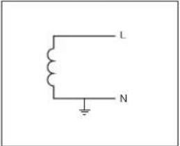 | ||||
| 6 | L_1 L_1 // L_2 L_2 L_3 // N | 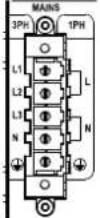 | Symbol “L1 // L2” (parallel connection) means connect the pole L1 together with the pole L2.The parallel connection must be done at the breaker output and not at the connector level.Symbol “n.c.” means not connected. | |
| Single-Phase: 2-Wire; Grounded Neutral; Contiguous Ground | ||||
| 7 | 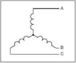 | A L_1 B L_2 C L_3 ↓ | 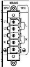 | |
| 3-Phase Wye: 3-Wire. | ||||
| 8 | 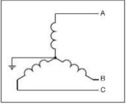 | A L_1 B L_2 C L_3 ↓ | 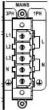 | |
| 3-Phase Wye: 3-Wire; Grounded Neutral Point. | ||||
| 9 | 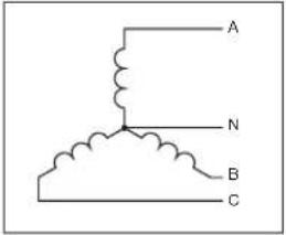 | A L_1 B L_2 C L_3 N N | 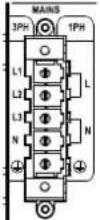 | |
| 3-Phase Wye: 4-Wire; Nongrounded Neutral. | ||||
| 10 | 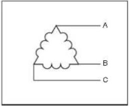 | A L_1 B L_2 C L_3 ↓ | 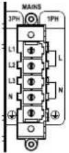 | |
| 3-Phase Delta: 3-Wire. | ||||
| 11 | 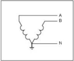 | A L_1 // L_2 B L_3 // N N n.c. | 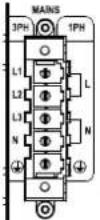 | Symbol “L1 // L2” (parallel connection) means connect the pole L1 together with the pole L2.The parallel connection must be done at the breaker output and not at the connector level.Symbol “n.c.” means not connected. |
| 3-Phase Delta: 3-Wire; Grounded Junction of Phases. | ||||
| 12 | 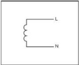 | A 10 L _1 // L _2 N 10 L _3 // N ± 10 ± | 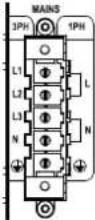 | Symbol “L1 // L2” (parallel connection) means connect the pole L1 together with the pole L2.The parallel connection must be done at the breaker output and not at the connector level.Symbol “n.c.” means not connected. |
| Single-Phase: 2-Wire; Nongrounded Neutral. | ||||
| 13 | 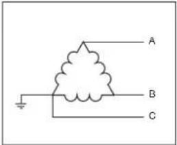 | A 10 L _1 B 10 L _2 C 10 L _3 ± 10 ± | 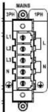 | |
| 3-Phase Delta: 3-Wire. | ||||

Specifications
Channel Handling
| Number of output channels | 4 mono,bridgeable per ch. pair |
| Number of input channels: | |
| Analog 4 (4x XLR) | |
| AES3 4 (2x XLR) | |
| DanteTM* 16 (2x RJ45) |
* DANTE version only
Audio
| Output NoiseA-Weighted @ 8 Ω - Analog to Analog / Digital to Analog | < -70.0 dBV |
| Dynamic RangeA-Weighted @ 8 Ω - Analog to Analog / Digital to Analog | 114,3 dB |
| Damping Factor @ 8 Ω, 20Hz - 500Hz > 5000 | |
| Slew Rate (Input filter bypassed) > 50 V/μs | |
| Frequency Response (-3 dB, 1 W @ 8 Ω) 5 Hz - 30 kHz | |
| Crosstalk (1 kHz) -70 dB | |
| THD+N (from 0.1 W to Full Power) | < 0.5%(typical < 0.01%) |
| DIM (from 0.1 W to Full Power) | < 0.5%(typical < 0.01%) |
| Input Impedance 20 kΩ Balanced | |
| Input Acceptance +27 dBu |
DSP
| AD converters | Dual 24 bit 48 kHz Tandem* architecture with 129 dBA of dynamic range |
| DA converters | Dual 24 bit 48 kHz Tandem* architecture with 121 dBA of dynamic range |
| Sample rate converter | 24 Bit @ 44.1 kHz to 192 kHz140 dB Dynamic Range - 0.0001 % THD+N |
| Internal precision 40 bit floating point | |
| Delay | up to 2 s on input sectionup to 100 ms per output for time alignment |
| Equalizer | Raised-cosine, custom FIR, parametric IIR: peaking, hi/lo-shelving, all-pass, band-pass, band-stop, hi/lo-pass |
| Crossover | Linear phase (FIR), hybrid (FIR-IIR), Butterworth, Linkwitz-Riley, Bessel: 6 dB/oct to 48 dB/oct (IIR) |
Limiters TruePower™, RMS voltage, RMS current, Peak limiter
Damping control Active DampingControl™
Construction
| Dimensions 483 mm x 44.5 mm x 495 mm (19.0 in x 1.75 in x 19.5 in) | |
| Weight 15 kg (33.0 lb) | |
Output Stage
| Maximum output power per channel @ 8 Ω 1600 W | |
| Maximum output power per channel @ 4 Ω 3000 W | |
| Maximum output power per channel @ 2.7 Ω | 4000 W |
| Maximum output power per channel @ 2 Ω 5200 W | |
| Maximum output power @ 8 Ω Bridged | 6000 W |
| Maximum output power @ 4 Ω Bridged | 10400 W |
| Peak total output, all channels driven | 20000 W |
| Maximum unclipped output voltage | 175 V peak |
| Maximum output current | 130 Apeak |
The power figure is calculated by driving and loading symmetrically all the channels: uneven loads allow to achieve highest performance.
AC Mains Power
| Single-Phase | |
| Nominal Voltage | 100 - 240 V @ 50/60Hz |
| Operating Range | 90 - 264 V from DC to 200Hz |
| Power Factor1/8 Maximum Output Power @ 4 Ω | >0.9 |
| Current Draw1/8 Maximum Output Power @ 4 Ω | 18 A_rms @ 100V9 A_rms @ 240V |
| Suggested circuit breaker C16 | |
Three-Phase
| Nominal Voltage** | 208Y / 120 - 416Y / 240 V, 3~, 3W+N+PE@ 50/60Hz200 V~, 3W+PE @ 50/60Hz | |
| Power Factor1/8 Maximum Output Power @ 4 Ω | >0.9 | |
| Current Drawn from Each Single Phase1/8 Maximum Output Power @ 4 Ω | 6 Arms@ 208Y | 3 Arms@ 416Y |
| Suggested circuit breaker (per phase) | C10 | |
Bi-Phase
| Nominal Voltage | 200/100 V, 2W+PE @ 50/60Hz |
| Idle Consumption (all AC MAINS cases) | < 100 W |
| Max Consumption (all AC MAINS cases) | < 3500 W |
** Note: 208Y/120 V = 208 V phase-to-phase, 120 V phase-to-neutral
Thermal
| Operating temperature | 0° - 15°C / 32° - 113°F | |
| Cooling | Fan, continuously variable speed, teperature controlled | |
| Thermal dissipation | ||
| Single phase | 115V | 230V |
| 1/8 Maximum Output Power @ 8 Ω | 1127 BTU/h | 1058 BTU/h |
| 1/4 Maximum Output Power @ 8 Ω | 2124 BTU/h | 1639 BTU/h |
X8

Specifications
| Channel Handling | |
| Number of output channels | 8 mono,bridgeable per ch. pair |
| Number of input channels: | |
| Analog 8 (8x XLR) | |
| AES3 8 (4x XLR) | |
| DanteTM* 16 (2x RJ45) | |
| * DANTE version only | |
| Audio | |
| Output NoiseA-Weighted @ 8 Ω - Analog to Analog / Digital to Analog | < -70.0 dBV |
| Dynamic RangeA-Weighted @ 8 Ω - Analog to Analog / Digital to Analog | 114,3 dB |
| Damping Factor @ 8 Ω, 20Hz - 500Hz > 5000 | |
| Slew Rate (Input filter bypassed) > 50 V/μs | |
| Frequency Response (-3 dB, 1 W @ 8 Ω) 5 Hz - 30 kHz | |
| Crosstalk (1 kHz) | -70 dB |
| THD+N (from 0.1 W to Full Power) | < 0.5%(typical < 0.01%) |
| DIM (from 0.1 W to Full Power) | < 0.5%(typical < 0.01%) |
| Input Impedance | 20 kΩ Balanced |
| Input Acceptance | +27 dBu |
| DSP | |
| AD converters | Dual 24 bit 48 kHz Tandem* architecture with 129 dBA of dynamic range |
| DA converters | Dual 24 bit 48 kHz Tandem* architecture with 121 dBA of dynamic range |
| Sample rate converter | 24 Bit @ 44.1 kHz to 192 kHz140 dB Dynamic Range - 0.0001 % THD+N |
| Internal precision | 40 bit floating point |
| Delay | up to 2 s on input sectionup to 100 ms per output for time alignment |
| Equalizer | Raised-cosine, custom FIR, parametric IIR: peaking, hi/lo-shelving, all-pass, band-pass, band-stop, hi/lo-pass |
| Crossover | Linear phase (FIR), hybrid (FIR-IIR), Butterworth, Linkwitz-Riley, Bessel: 6 dB/oct to 48 dB/oct (IIR) |
| Limiters | TruePowerTM, RMS voltage, RMS current, Peak limiter |
Damping control Active DampingControl™
| Construction | |
| Dimensions | 483 mm x 89 mm x 495 mm (19.0 in x 3.5 in x 19.5 in) |
| Weight | 24 kg (52.9 lb) |
| Output Stage | |
| Maximum output power per channel @ 8 Ω | 1600 W |
| Maximum output power per channel @ 4 Ω | 3000 W |
| Maximum output power per channel @ 2.7 Ω | 4000 W |
| Maximum output power per channel @ 2 Ω | 5200 W |
| Maximum output power @ 8 Ω Bridged | 6000 W |
| Maximum output power @ 4 Ω Bridged | 10400 W |
| Peak total output, all channels driven | 40000 W |
| Maximum unclipped output voltage | 175 V peak |
| Maximum output current | 130 Apeak |
The power figure is calculated by driving and loading symmetrically all the channels: uneven loads allow to achieve highest performance.
| AC Mains Power | |
| Single-Phase | |
| Nominal Voltage 100 - 240 V @ 50/60Hz | |
| Operating Range 90 - 264 V from DC to 200Hz | |
| Power Factor1/8 Maximum Output Power @ 4 Ω | >0.9 |
| Current Draw1/8 Maximum Output Power @ 4 Ω | 32 A_rms @ 100V18 A_rms @ 240V |
| Suggested circuit breaker C32 | |
| Three-Phase | |
| Nominal Voltage** | 208Y / 120 - 416Y / 240 V, 3~, 3W+N+PE@ 50/60Hz200 V~, 3W+PE @ 50/60Hz |
| Power Factor1/8 Maximum Output Power @ 4 Ω | >0.9 |
| Current Drawn from Each Single Phase1/8 Maximum Output Power @ 4 Ω | 12 Arms@ 208Y 6 Arms@ 416Y |
| Suggested circuit breaker (per phase) C16 | |
| Bi-Phase | |
| Nominal Voltage 200/100 V, 2W+PE @ 50/60Hz | |
| Idle Consumption (all AC MAINS cases) < 200 W | |
| Max Consumption (all AC MAINS cases) | < 5000 W |
** Note: 208Y/120 V = 208 V phase-to-phase, 120 V phase-to-neutral
| Thermal | ||
| Operating temperature | 0° - 15°C / 32° - 113°F | |
| Cooling | Fan, continuously variable speed, teperature controlled | |
| Thermal dissipation | ||
| Single phase | 115V | 230V |
| 1/8 Maximum Output Power @ 8 Ω | 2117 BTU/h | 1946 BTU/h |
| 1/4 Maximum Output Power @ 8 Ω | 3892 BTU/h | 2875 BTU/h |
X4L

Specifications
| Channel Handling | |
| Number of output channels 4 mono | |
| Number of input channels: | |
| Analog 4 (4x XLR) | |
| AES3 4 (2x XLR) | |
| Dante** 16 (2x RJ45) | |
| * DANTE version only | |
| Audio | |
| Gain | 17 dB - 47 dB(0.1 dB increments) |
| Default Gain 32 dB | |
| Output NoiseA-Weighted @ 8 Ω - Analog to Analog / Digital to Analog | <-67 dBV /<-67.5 dBV |
| Dynamic RangeA-Weighted @ 8 Ω - Analog to Analog / Digital to Analog | 113.5 dB / 114 dB |
| Damping Factor @ 8 Ω, 20Hz - 500Hz > 5000 | |
| Slew Rate (input filter bypassed) > 50 V/μs | |
| Frequency Response (-3 dB, 1 W @ 8 Ω) 5 Hz - 22.5 kHz | |
| Crosstalk (1 kHz) -70 dB | |
| THD+N (from 0.1 W to Full Power) | < 0.5%(typical < 0.01%) |
| DIM (from 0.1 W to Full Power) | < 0.5%(typical < 0.01%) |
| Input Impedance 20 kΩ Balanced | |
| Input Acceptance +27 dBu | |
| DSP | |
| AD converters | Dual 24 bit 48 kHz Tandem* architecture with 129 dBA of dynamic range |
| DA converters | Dual 24 bit 48 kHz Tandem* architecture with 121 dBA of dynamic range |
| Sample rate converter | 24 Bit @ 44.1 kHz to 192 kHz140 dB Dynamic Range - 0.0001 % THD+N |
| Internal precision | 40 bit floating point |
| Delay | up to 2 s on Input sectionup to 100 ms per output for time alignment |
| Equalizer | Raised-cosine, custom FIR, parametric IIR: peaking, hi/lo-shelving, all-pass, band-pass, band-stop, hi/lo-pass |
| Crossover | Linear phase (FIR), hybrid (FIR-IIR), Butterworth, Linkwitz-Rilley, Bessel: 6 dB/oct to 48 dB/oct (IIR) |
| Limiters | TruePowerTM, RMS voltage, RMS current, Peak limiter |
| Damping control | Active DampingControlTM |
| Construction | |
| Dimensions | 483 mm x 88 mm x 495 mm (19.0 in x 3.5 in x 19.5 in) |
| Weight | 24 kg (52.9 lb) |
| Output Stage | Symmetrical* Asymmetrical** | |
| Maximum output power per channel @ 8 Ω 4800 W 5000 W | ||
| Maximum output power per channel @ 4 Ω 6800 W 8400 W | ||
| Maximum output power per channel @ 2.7 Ω | 7700 W 9600 W | |
| Maximum output power per channel @ 2 Ω | 8200 W | 10000 W |
| Peak total output, all channels driven | 32800 W | |
| Maximum unclipped output voltage | 300 V peak | |
| Maximum output current | 140 Apeak | |
*Measured by driving and loading symmetrically all the channels. **Measured with half the channels at the stated power and the other channels at 25% of that power (i.e. -6 dB)
| AC Mains Power | ||
| Single Phase | ||
| Nominal Voltage | 100 - 240 V @ 50/60Hz | |
| Operating Range | 90 - 264 V from DC to 200 Hz | |
| Current Draw1/8 Maximum Output Power ^1 | 26 A_rms @115V | 13 A_rms @230V |
| Suggested circuit breaker | C32 | C32 / C16 |
| Three Phase | ||
| Nominal Voltage | 173Y / 100 - 416Y / 240 V | |
| 3~, 3W+N+PE / 3W+PE | ||
| Current Drawn from Each Single Phase1/8 Maximum Output Power ^1 | 9 A_rms @ 199V Ythree phase 115V | 5 A_rms @ 400V Ythree phase 230V |
| Suggested circuit breaker (per phase) | C16 | |
| Idle Consumption (all AC MAINS cases) | < 230 W | |
| Max consumption (all AC MAINS cases) | < 5000 W | |
1/8 Maximum Output Power into a typical 4 Ω loudspeaker
| Thermal | ||
| Operating temperature | 0° - 35°C / 32° - 95°F | |
| Cooling | Fan, continuously variable speed, temperature controlled | |
| Fan Noise - 1/8 Maximum Output Power (1m)1 | 40 dBA SPL | |
| Thermal dissipation | ||
| Single phase | 115V | 230V |
| 1/8 Maximum Output Power1 | 2970 BTU/h | 3650 BTU/h |
^1 1/8 Maximum Output Power into a typical 4 Ω loudspeaker. This is lower than with a resistive dummy load thanks to the reactive behavior of loudspeakers. Please see our white paper about this.

DRIVING HUMAN AUDIO EXPERIENCE
POWERSOFT S.P.A.
Via E. Conti, 5 - Scandicci (FI) 50018 - Italy
support@powersoft.com
+39 055 73 50 230
+39 055 73 56 235
POWERSOFT.COM
- Table of contents Table des matières
- X Series 17
- Installation 18
- LED chart 22
- Networking 23
- ArmoníaPlus 24
- 9.Warranty and assistance 25
- B
- English
- X8 Rear panel
- X4-X4L Rear panel
- Française
- Panneau arrière X8
- Español
- Panneau avant X8
- L M
- N
- 0
- Regulatory information
- FCC COMPLIANCE NOTICE
- CAUTION: Changes or modifications not expressly approved by the party responsible for compliance could void the user's authority to operate the equipment.
- WEEE DIRECTIVE
- EC DECLARATION OF CONFORMITY
- Important safety instructions
- EXPLANATIONS OF GRAPHICAL SYMBOLS
- CAUTION
- RISK OF ELECTRICK SHOCK DO NOT OPEN
- 2:1.Welcome
- 2:2. Unpacking & checking for shipping damage
- 2:3.Disposal of the packaging material
- 2:4.List of image panels
- Installation
- 3:1.Location
- 3:2.Cooling
- 3:3.Cleaning
- Disconnect the AC mains source before attempting to clean any part of the amplifier
- 3:4.AC mains supply
- This device must be powered exclusively by earth connected mains sockets in electrical works compliant to the IEC 364 or similar rules.
- Provide a sectioning breaker between the mains connections and the amplifier.
- AC mains connections must be performed only by professional or qualified personnel according to local electrical authoritie guidelines.
- 3:4.1. Three-phase electric power
- 3:4.2. Two-phase electric power
- 3:4.3. Single-phase electric power
- 3:5.Precautions regarding installation
- WARNING: TO PREVENT FIRE OR ELECTRIC SHOCK
- 3:6.Switch on
- 3:7.Switch off
- 3:8.Mute
- 3:9.Wi-Fi switch
- Wi-Fi
- 4
- 192.168.0.1
- Connections
- 5:1.Signal grounding
- 5:2.Analog audio input connections
- 5:3. Digital audio input connections
- 5:4.Output connections
- CLASS 3 WIRING
- 5:5.Ethernet connections
- Software update LED chart
- 6
- 7
- update-version#-model.bin
- 8:1.IP addressing
- 8:1.1. IP Addressing troubleshooting
- As a rule of thumb, turn the DHCP server on before connecting the amplifiers.
- 8:2.Dante™ networking
- 8:2.1. Redundant network configuration
- ArmoníaPlus
- 9:1. Signal routing and DSP architecture
- 9:2.Purposed workflow
- Warranty and assistance
- 10:1.Warranty
- 10:1.1.Product warranty
- 10:1.2. Return of Goods
- 10:1.3. Repair or replacement
- 10:1.4. Cost and responsibility of transport
- 10:2.Assistance
- 3:7.Eteindre
- 3:4. 交流电源
- 3:7. 关闭
- 3:7.Ausschalten
- https://armonia.powersoft.it/
- 9:1.Roteamento de sinal e arquitetura DSP
- X Series Mains Wiring Option
- Specifications
- X4L
Brand : Powersoft
Model : X4L
Category : Audio Amplifier