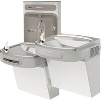
EZOTL8WSLK - Water fountain Elkay - Free user manual and instructions
Find the device manual for free EZOTL8WSLK Elkay in PDF.


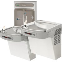
| Product Type | Refrigerated Water Fountain with Bottle Filler |
| Brand | Elkay |
| Model | EZOTL8WSLK |
| Refrigerant | HFC-134A |
| Power Supply | 115 V, 60 Hz, 8 A (estimate for standard cooler) |
| Required Electrical Protection | Ground Fault Circuit Interrupter (GFCI) |
| Factory Set Vapor Pressure | 35 psi |
| Stream Adjustment | Screw under push bar; adjust so stream hits basin at 165 mm from bubbler |
| Main Functions | Water cooling, bottle filling, push-button dispensing |
| Panel Material | Stainless steel, mirror finish |
| Maintenance and Cleaning | Warm soapy water or mild cleaner; avoid abrasive, corrosive, or petroleum-based products |
| Mirror/Stainless Steel Cleaning | Mild soap and water or Windex with a soft cloth |
| Safety | Disconnect before any repair; mandatory installation with GFCI |
| Installation | Wall mounting bracket, water and drain connection, electrical connection |
| Included Accessories | Mounting bracket, trap, front and lower panels |
| Repairability | Access via front and lower panels; replaceable components: bubbler, solenoid valve, regulator, switches |
| Manufacturer's Warranty | Void if corrosive or abrasive chemicals used |
| Approximate Dimensions | Height: 102 cm, Width: 41 cm, Depth: 36 cm (estimate for similar model) |
| Approximate Weight | 25 kg (estimate for cooler with filler) |
Frequently Asked Questions - EZOTL8WSLK Elkay
User questions about EZOTL8WSLK Elkay
0 question about this device. Answer the ones you know or ask your own.
Ask a new question about this device
Download the instructions for your Water fountain in PDF format for free! Find your manual EZOTL8WSLK - Elkay and take your electronic device back in hand. On this page are published all the documents necessary for the use of your device. EZOTL8WSLK by Elkay.
USER MANUAL EZOTL8WSLK Elkay
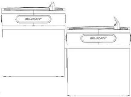
*Versatile Cooler Model LZSTL8WSLK configuration as shipped
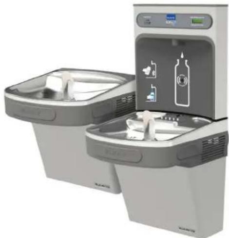
*Versatile cooler design allows units to be installed either left-hand high and right-hand low or left-low and right high.
Basin change may be required. See desired rough-in to help determine if the basin change is necessary.
Refrigerated unit must be installed on right-hand side.
*Versatile Cooler Model LZSTL8WSLK alternate installations

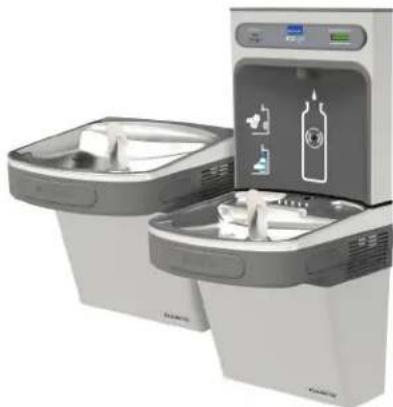
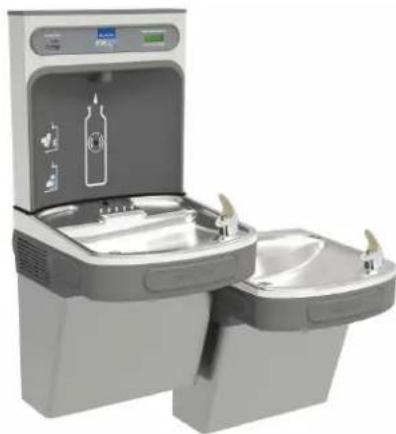
Note: Danger! Electric shock hazard. Disconnect power before servicing unit.
Pictured is unit only without bottle fi Iler.
Fig. 2
REDUCE HEIGHT BY 3 INCHES FOR INSTALLATION OF CHILDREN'S ADA COOLER
LEGEND/LEYENDA/LÉGENDE A - RECOMMENDED WATER S
(76mm) MAXIMUM OUT FROM WALL
La UBICACION 3/8 O RECOMENDADA de ABASTECIMIENTO DE AGUA. D. El TUBO del COBRE DE UNPLATED CONECTA TALONARIO CON APAGO (POR OTROS) 3 en. (76 Mm) el MAXIMO FUERA DE PARED
L.O.D de 3/8 d'EMPLACEMENT DE PROVISION D'EAU RECOMMANDE. LE TUBE DE CUIVRE DE UNPLATED CONNECTE STUB AVEC ETEINT (PAR
LES AUTRES) 3 dans. (76 mm) le MAXIMUM HORS DU MUR
B = RECOMMENDED LOCATION FOR WASTE OUTLET 1-1/2" O.D. DRAIN STUB 2 IN. OUT FROM WALL
UBICACIÓN RECOMENDADA PARA EL DRENAJE DE SALIDA DE AGUA, DE 1-1/2" DE DIÁMETRO. EI TALONARIO 2 FUERA DE PARED
EMPLACEMENT RECOMMANDÉ POUR LE DRAIN DE D.E. 1-1/2" DE SORTIE D'EAU. STUB 2 HORS DU MUR
C = 1-1/2" TRAP NOT FURNISHED
PURGADOR DE 1-1/2" NO PROPORCIONADO
SIPHON 1-1/2" NON FOURNI
A = RECOMMENDED WATER SUPPLY LOCATION 3/8 O.D. UNPLATED COPPER TUBE CONNECT STUB WITH SHUT OFF (BY OTHERS) 3 IN.
NOTE: IT IS HIGHLY RECOMMENDED THAT THE CIRCUIT BE DEDICATED AND THE LOAD PROTECTION BE SIZED FOR 20 AMPS.
LEGEND/LEYENDA/LÉGENDE D = ELECTRICAL SUPPLY (3) WIRE RECESSED BOX DUPLEX OUTLET**
Fig. 3
REDUCE HEIGHT BY 3 INCHES FOR INSTALLATION OF CHILDREN'S ADA COOLER
LEGEND/LEYENDA/LÉGENDE
A = RECOMMENDED WATER S
SUMINISTRO ELÉCTRICO (3) CAJA ENCHUFE DE ALAMBRE SALIDA DUPLEX
LA UBICACIÓN 3/8 O RECOMENDADA DE ABASTECIMIENTO DE AGUA. D. EL TUBO DEL COBRE DE UNPLATED CONECTA TALONARIO CON APAGO (POR OTROS) 3 en. (78 mm) el MAXIMO FUERA DE PARED L'O.D. de 3/8 d'EMPLACEMENT DE PROVISION D'EAU RECOMMANDE. LE TUBE DE CUIVRE DE UNPLATED CONNECTE STUB AVEC ETEINT (PAR LES AUTRES) 3 dans. (76 mm) le MAXIMUM HORS DU MUR B = RECOMMENDED LOCATION FOR WASTE OUTLET 1-1/2" O.D. DRAIN STUB 2 IN. OUT FROM WALL UBICACIÓN RECOMENDADA PARA EL DRENAJE DE SALIDA DE AGUA, DE 1-1/2" DE DIÁMETRO. EL TALONARIO 2 FUERA DE PARED EMPLACEMENT RECOMMANDE POUR LE DRAIN DE D.E. 1-1/2" DE SORTIE D'EAU. STUB 2 HORS DU MUR C = 1-1/2" TRAP NOT FURNISHED PURGADOR DE 1-1/2" NO PROPORCIONADO SIPHON 1-1/2" NON FOURNI
NOTE: IT IS HIGHLY RECOMMENDED THAT THE CIRCUIT BE DEDICATED AND THE LOAD PROTECTION BE SIZED FOR 20 AMPS.
LEGEND/LEYENDA/LÉGENDE
D = ELECTRICAL SUPPLY (3) WIRE RECESSED BOX DUPLEX OUTLET**
SUMINISTRO ÉLECTRICO (3) CAJA ENCHUFE DE ALAMBRE SALIDA D'UPLEX
ALIMENTATION ÉLECTRIQUE (3) BOÎTIER ENCASTRÉ
E = INSURE PROPER VENTILATION BY MAINTAINING 6" (152 mm) (MIN.) CLEARANCE FROM CABINET LOUVERS TO WALL.
ASEGURE UNA VENTILACIÓN ADECUADA MANTENIENDO UN ESPACIO E 6" (152 mm) (MIN.) DE HOLGURA ENTRE LA REJILLA DE VENTILACIÓN DEL MUEBLE Y LA PARED.
ASSUREZ-VOUS UNE BONNE VENTILATION EN GARDANT 6" (152 mm) (MIN.) ENTRE LES ÉVENTS DE L'ENCEINTE ET LE MUR.
10 DOLE PARES FOR FASTENING UNIT TO WALL
AGUJEROS DE LAS TUERCAS DE 7/16 PARA SUETAR LA UNIDAD A LA PARED
TROUS D'ÉCROUS 7/16 POUR FIXER L'APPAREIL AU MUR
**NEW INSTALLATIONS MUST USE GROUND FAULT CIRCUIT INTERRUPTER (GFCI)
*Las nuevas instalaciones deben utilizar el interruptor de circuito de tierra de la averla (GFCI)
**Les nouvelles installations doivent employer l'interrupteur de circuit moulu de défaut (GFCI)
REFRIGERATED UNIT MUST BE INSTALLED ON RIGHT-HAND SIDE.
ALTERNATE ROUGH-IN FOR RIGHT-HAND HIGH, BOTTLE FILLER HIGH MODELS
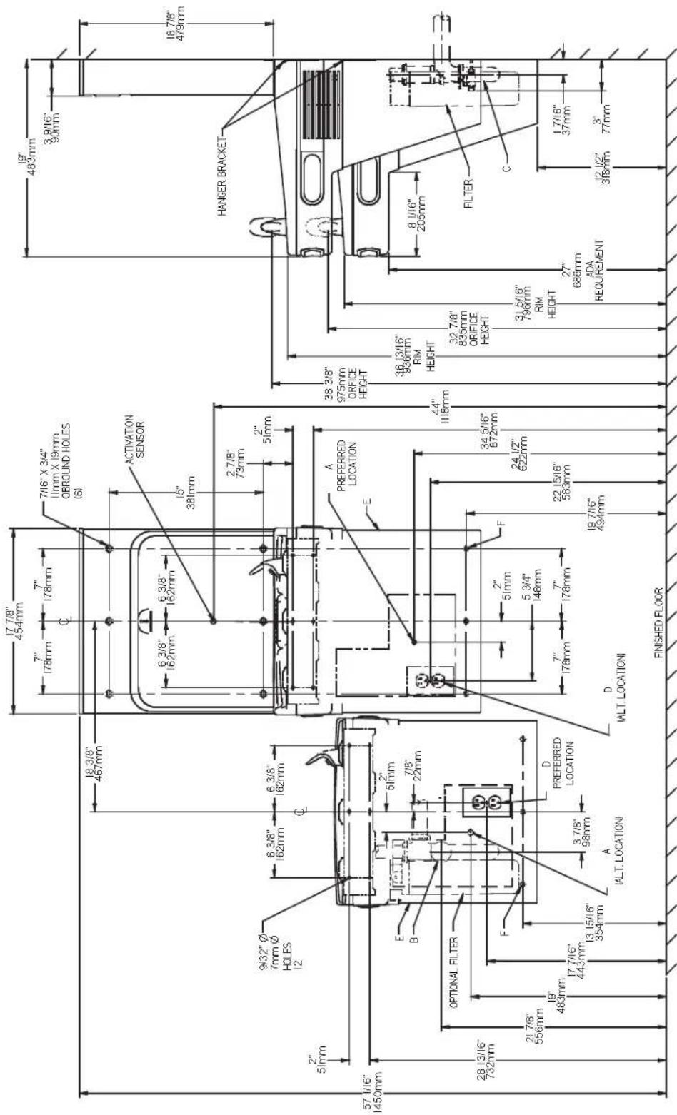
Fig. 4
REDUCE HEIGHT BY 3 INCHES FOR INSTALLATION OF CHILDREN'S ADA COOLER
LEGEND/LEYENDA/LÉGENDE
D = ELECTRICAL SUPPLY (3) WIRE RECESSED BOX DUPLEX OUTLET™
SUMINISTRO ELECTRICO (3) CAJA ENCHUFE DE ALAMBRE SALIDA DUPLEX
ALIMENTATION ELECTRIQUE (3) BOITIER ENCASTRE
E = INSURE PROPER VENTILATION BY MAINTAINING 6" (152 mm) (MIN.) CLEARANCE FROM CABINET LOUVERS TO WALL.
ASEGURE UNA VENTILACION ADECUADA MANTENIENDO UN ESPACIO E 6° (152 mm) (MIN.) DE HOLGURA ENTRE LA REJILLA
DE VENTILACIÓN DEL MUEBLE Y LAPAKED.
ARRIENEZ DAVIN LA QUE DANIE VENTILACIÓN EN CABBAGE (FEA)..../AMILENEE LE FEEFERA DE LEMAFINEE EL MUN
ASSOREZ-VOUS ONE BONNE VENTILATION EN GARDANT 6 (152 mm) (MIN.) EN F=748 BOLT HOLES FOR FASTENING UNIT TO WALL
AGUEROS DE LAS TIERCAS DE 7/16 PARA SUJETAR LA UNIDAD A LARABED
TROUS D'ÉCROUS 7/16 POUR EIXER L'APPAREIL AUMUR
**NEW INSTALLATIONS MUST USE GROUND FAULT CIRCUIT INTERRUPTER (GFCI)
"Las nuevas instalaciones deben utilizar el interruptor de circuito de tierra de la averla (GFCI)
**Les nouvelles installations doivent employer l'interrupteur de circuit moulu de défaut (GFCI)
(1) 2017年,公司与上海浦东发展银行股份有限公司签订了《关于使用部分闲置募集资金进行现金管理的协议》。
REFRIGERATED UNIT MUST BE INSTALLED ON RIGHT-HAND SIDE.
LEGEND/LEYENDA/LÉGENDE
A = RECOMMENDED WATER S
(76mm) MAXIMUM OUT FROM WALL
La UBICACION 3/8 O RECOMENDADA de ABASTECIMIENTO DE AGUA. D. EL TUBO del COBRE de UNPLATED CONECTA TALONARIO CON APAGO
(POR OTROS) 3 en. (76 Mm) el MAXIMO FUERA DE PARED
L'O.D de 3/8 d'EMPLACEMENT DE PROVISION D'EAU RECOMMANDE. LE TUBE DE CUIVRE DE UNPLATED CONNECTE STUB AVEC ETEINT (PAR
LES AUTRES) 3 dans. (70 mm) LE MAXIMUM HOKS DU MUK
B = RECOMMENDED LOCATION FOR WASTE OUTLET THZ O.D. DRAIN STUD ZIN. OUT FROM WALL
URICACIÓN RECOVENADA PARA EL PROFICA DE CHILDA DE LOJA DE 41 DE BIJETO DE FLATONARIO DE PUEBA DE BADER
VOLIVATION REQUILENTURA FINS LE D'ENOVE DE VALIDA DE NOVA, DE PHE DE DIAMETRY, ET INONANIX ET VENA DE TAKED EMBI APEMENT RECOMMANDE BOLDI E BAIN DE R E 4.40° DE CARTIE NEATH STIR O WIDE DU MING
C = 1.4/2" TRAP NOT FURNISHED
PURGADOR DE 1-1/2" NO PROPORCIONADO
SIPHON 1-1/2" NON FOURNI
公司与华电电力股份有限公司的关联交易
NOTE: IT IS HIGHLY RECOMMENDED THAT THE CIRCUIT BE DEDICATED AND THE LOAD PROTECTION BE SIZED FOR 20 AMPS.
ALTERNATE ROUGH-IN FOR LEFT-HAND HIGH, BOTTLE FILLER HIGH MODELS
REQUIRES BASIN ASSY CHANGE. SEE PAGES 11-13 FOR INSTRUCTIONS
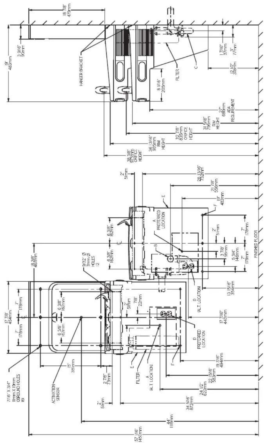
Fig. 5
REDUCE HEIGHT BY 3 INCHES FOR INSTALLATION OF CHILDREN'S ADA COOLER
LEGEND/LEYENDA/LÉGENDE
ELECTRICAL SUPPLY (3) WIRE RECESSED BOX DUPLEX OUTLET ™ SUMINISTRO ELECTRICO (3) CAJA ENCHUFE DE ALAMBRE SALIDA DUPLEX
ALIMENTATION ELECTRIQUE (3) BOITIER ENCASTRE
E = INSURE PROPER VENTILATION BY MAINTAINING 6" (152 mm) (MIN.) CLEARAN
A = RECOMMENDED WATER SUPPLY LOCATION 3/8 O.D. UNPLATED COPPER TUBE CONNECT STUB WITH SHUT OFF (BY OTHERS) 3 IN. (76mm) MAXIMUM OUT FROM WALL
C = 1-1/2" TRAP NOT FURNISHED
PORGADOR DE 1-1/2" NO IMP SIPHON 1-1/2" NON FOURNI
NOTE: IT IS HIGHLY RECOMMENDED THAT THE CIRCUIT BE DEDICATED AND THE LOAD PROTECTION BE SIZED FOR 20 AMPS.
HANGER BRACKETS INSTALLATION
1) Remove hanger brackets fastened to back of cooler by removing one (1) screw.
2) Mount the hanger brackets as shown in Figures 2, 3, 4 or 5.
NOTE: Hanger Bracket MUST be supported securely. Add fixture support carrier if wall will not provide adequate support. Anchor hanger securely to wall using all six (6) 1/4 in. dia. mounting holes.
INSTALLATION OF COOLER
3) Hang the cooler on the hanger bracket. Be certain the hanger bracket is engaged properly in the slots on the cooler back as shown in Figures 2, 3, 4 or 5.
4) Remove the four (4) screws holding the lower front panel at the bottom of cooler. Remove the front panel by pulling straight down and set aside.
5) Connect water inlet line--See Note 4 of General Instructions.
6) Install trap. Remove the slip nut and gasket from the trap and install them on the cooler waste line making sure that the end of the waste line fits into the trap. Assemble the slip nut and gasket to the trap and tighten securely.
IMPORTANT: If it is necessary to cut the drain, loosen the screw at the black rubber boot and remove tube, check for leaks after re-assembly.
7) Install bottle filler per page (11)
8) Plug in electrical power. Unit must have electrical power to have water flow.
START UP
Also See General Instructions
9) Stream height is factory set at 35 PSI. If supply pressure varies greatly from this, adjust screw located on the right knee clearance area. CW adjustment will raise stream and CCW adjustment will lower stream. For best adjustment, stream should hit basin approximately 6-1/2" (165mm) from bubbler on the downward slope of the basin.
NOTE: If continuous flow occurs at the end of the compressor cycle, turn cold control counterclockwise 1/4 turn.
10) Replace the front panel ensuring that the metal wrapper is secured inside of the upper shroud. Replace all four screws previously removed.
CLEANING
Warm, soapy water or mild household cleaning products can be used to clean the exterior panels of the EZ coolers. Extra caution should be used to clean the mirror finished stainless steel panels. They can be easily scratched and should only be cleaned with mild soap and water or Windex glass cleaner and a clean, soft cloth. Use of harsh chemicals or petroleum based or abrasive cleaners will void the warranty.
View of Underside of Basin Shroud
Stream Height Adjustment Location
Service Instructions
Lower and Upper Shroud
To access the refrigeration system and plumbing connections, remove four screws from bottom of cooler to remove the lower shroud. To remove the upper shroud for access to the pushbars, regulator, solenoid valve or other components located in the top of the unit, remove lower shroud, disconnect drain, remove four screws from tabs along lower edge of upper shroud, unplug two wires and water tube.
Bubbler
To remove the bubbler, fi rst disconnect the power supply. The underside of the bubbler can be reached through the access panel on the underside of the upper shroud. Remove the access panel by removing the retaining screw. To remove the bubbler, loosen locknut from the underside of the bubbler and remove the tubing from the quick connect fitting per the Operation Of Quick Connect Fittings section in the General Instructions. After servicing, replace the access panel and retaining screw.
Switches Behind the Push Bar
The regulator in an EZ cooler is always held fully open by the use of a single regulator nut (See Fig. 6 or 7). Water is not dispensed until the pushbar is depressed to activate a switch which then opens a solenoid valve. When installing the regulator nut, the regulator spring must be depressed while turning the nut.
To remove sidebars, from the inside compress the flared tabs and pull out carefully. To reinstall side pushbars, the front of the pushbar is inserted first. While keeping the switch depressed, snap the rear of the pushbar into position.
Fig. 8 Fig. 9
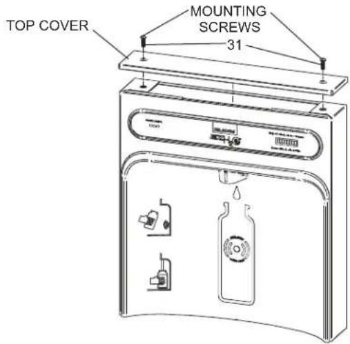
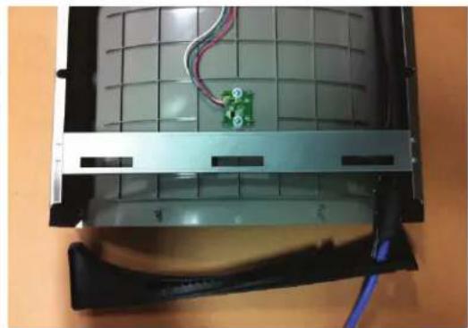
Fig. 10
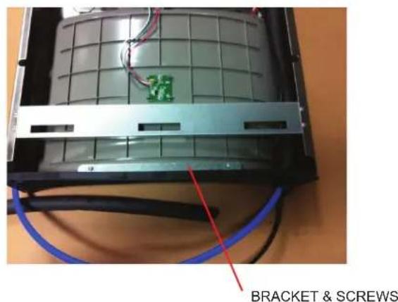
Fig. 11
Bottle Filler Installation Instructions
1) Remove two (2) mounting screws with 5/32" Allen wrench holding top cover to Bottle Filler (See Fig. 9). Remove top cover. Note do not discard mounting screws, they will be needed to reinstall top cover.
2) Remove wall mounting plate from Bottle Filler. Place wall plate against wall on top of basin. Center the wall plate side to side with the basin. Mark the six (6) mounting holes with a pencil (See Fig. 2, 3, 4 or 5).
3) Remove wall mounting plate from wall. NOTE: Mounting plate MUST be supported securely. Add fixture support carrier if wall will not provide adequate support.
4) Install wall mounting plate to wall using six (6) 7/16" obround mounting holes (mounting bolts not included) (See Fig. 8). Use appropriate fasteners for your wall type.
5) Lay Bottle Filler on water cooler basin and cut insulation from tube even with bottom of gasket, remove this insulation from the 3/8" tube, but do not discard.
Feed the power cord and waterline through the hole on top of water cooler. NOTE: To prevent scratching the basin place a towel or soft cloth over the entire basin when working above it.
6) Install gasket on bottom of bottle filler tower with gasket support bracket & (2) screws (See Fig. 11).
7) Feed power cord & 3/8" water line through hole in tower/basin gasket (See Fig. 10).
8) With the power cord, wire(s), and waterline through hole on top of water cooler place Bottle Filler on the three (3) angled tabs protruding from the wall mounting plate installed on wall. Make sure round boss in gasket fi ts in hole of basin.
9) Once Bottle Filler is installed on wall plate tabs, water line, wire(s) and power cord are installed properly, push top of Bottle Filler toward wall and line up top cover two (2) holes.
10) Reinstall Top Cover on Bottle Filler (See Fig. 9) with two mounting screws from step 1 above. Caution, do not over tighten screws.
11) Install remaining tube insulation to the water line from bottle filler, connect Bottle Filler waterline inside of the water cooler by connecting the 3/8" water line to the tee.
12) Install filter cartridge, remove filter from carton, remove protective cap, attach filter to filter head by firmly inserting into head and rotating filter clockwise.
13) Turn water supply on and inspect for leaks. Fix all leaks before continuing.
14) Once unit has been inspected for leaks and any leaks found corrected, plug Bottle Filler and unit into wall. Be sure to reinstall fuse to the circuit or switch the circuit breaker back to the "ON" position.
15) Once power is applied to Bottle Filler, the GREEN LED light should illuminate showing good filter status along with the LCD Bottle Counter.
16) Verify proper dispensing by placing cup, hand, or any opaque object in front of sensor area and verify water dispenses. Note: the first initial dispenses might have air in line which may cause a sputter. This will be eliminated once all air is purged from the line.
17) Once unit tests out, install Lower Panel back on water cooler(s). Unit is now ready for use.
BF11 - BF12 PROGRAM
SETTING THE CONTROL BOARD
VERIFY CONTROL BOARD SOFTWARE
1) To verify the software program of the control board the unit will need to be shut down and restarted. The chiller (if present) does not need to be shut down and restarted.
2) The units lower panel must be open to access the power cord and wall outlet.
3) Shut down the unit by unplugging the power cord from the wall outlet or switching off the circuit breaker to the unit.
4) Restart the unit by plugging the power cord back into the wall outlet.
5) Upon start up, the bottle count display will show the software designation of BF11 or BF12.
ACCESSING THE PROGRAMMING BUTTON
1) To access the program button, remove the top cover of the bottle-filler. Remove the two (2) screws holding top cover to bottle-filler with a 5/32" allen wrench. Remove top cover. Do not discard mounting screws, they will be needed to reinstall the top cover after programming operations are completed. The programming button is located at the top right side of the unit on the control board. NOTE: When applicable, there is also an alternate reset button located on the lower part of the water cooler. After removing the bottom cover, the reset button will be located on the left side of the cooler, mounted on the side panel support.
RESET THE FILTER MONITOR
1) Instructions apply to filtered units only.
2) Depress the program button for approximately 2 seconds until the display changes then release. The display will change and scroll through two messages:
"RST FLTR" – Reset Filter Monitor
"SETTINGS" – System Settings Sub Menu
If the program button is not pushed again the display will scroll through the two messages above for three cycles and then default back to bottle count and be back in run mode.
3) When the display changes to "RST FLTR", depress the button again. The display will change to show "FLTR =". Depress the button again and the display will show "FLTR =0"
4) The Green LED should be illuminated indicating that the visual filter monitor has been reset.
SETTING RANGE OF THE IR SENSOR WHERE APPLICABLE
1) Depress the program button for approximately 2 seconds until the display changes then release. The display will change and scroll through two messages: "RST FLTR" – Reset Filter Status LED "SETTINGS" – System Settings Sub Menu If the program button is not pushed again the display will scroll through the two messages above for three cycles and then default back to bottle count and be back in run mode.
2) When the display changes to "SETTINGS", depress the button again. The display will change to show
"RNG SET" - Range set for IR sensor.
"UNIT TYP" - Type of unit (REFRIG or NON-RFRG)
"FLT SIZE" - Select filter capacity
"RST BCNT" - Reset bottle count
3) When display shows "RNG SET" push program button once the display will show current value (can be 1 - 10) e.g. "RNG = 3".
4) Once display shows current value push the program button to scroll through value of 1 - 10. Select the desired range setting, "1" being closest to sensor and "10" being farthest away.
5) Once range is selected allow approximately 4 seconds to pass and then the display will go back to bottle counter and be in run mode.
6) Test bottle filler by placing bottle or hand in front of sensor to make sure water is dispensed.
3) When display shows "RNG SET" push program button once the display will show current value (can be 1 - 10) e.g. "RNG = 3". 4) Once display shows current value push the program button to scroll through value of 1 - 10. Select the desired range setting, "1" being closest to sensor and "10" being farthest away. 5) Once range is selected allow approximately 4 seconds to pass and then the display will go back to bottle counter and be in run mode. 6) Test bottle filler by placing bottle or hand in front of sensor to make sure water is dispensed.
SETTING UNIT TYPE
1) Depress the program button for approximately 2 seconds until the display changes then release. The display will change and scroll through two messages:
"RST FLTR" – Reset Filter Status LED
"SETTINGS" – System Settings Sub Menu
If the program button is not pushed again the display will scroll through the two messages above for three cycles and then default back to bottle count and be back in run mode.
Continued from below:
2) When the display changes to "SETTINGS", depress the button again.
The display will change to show
"RNG SET" - Range set for IR sensor.
"UNIT TYP" - Type of unit (REFRIG or NON-RFRG)
"FLT SIZE" - Select filter capacity
"RST BCNT" - Reset bottle count
3) When display shows "UNIT TYPE" push program button once the display will show current value. Can be REFRIG or NON-RFRG
4) Push button once to change value. Once value is selected the display will show the new value. (Can be REFRIG or NON-RFRG) "REFRIG" - stands for refrigerated product. In this setting the flow rate is estimated at 1.0 gallon per minute.
"NON-RFRG" - stands for nonrefrigerated product. In this setting the flow rate is estimated at 1.5 gallons per minute. Both "REFRIG" and "NON-RFRG" simulate 1 bottle equal to 20 oz.
5) Allow approximately 4 seconds to pass and the display will return to bottle counter and be in run mode.
RESETTING BOTTLE COUNT
1) Depress the program button for approximately 2 seconds until the display changes then release. The display will change and scroll through two messages:
"RST FLTR" – Reset Filter Status LED
"SETTINGS" – System Settings Sub Menu
If the program button is not pushed again the display will scroll through the two messages above for three cycles and then default back to bottle count and be back in run mode.
2) When the display changes to "SETTINGS", depress the button again. The display will change to show:
"RNG SET"- Range set for IR sensor.
"UNIT TYP" - Type of unit (REFRIG or NON-RFRG)
"FLT SIZE" - Select filter capacity
"RST BCNT" - Reset bottle count
If the button is not pushed again the display will scroll through the four messages above for three cycles and return to run mode.
3) When display shows "RST BCNT" push program button once the display will show current value, e.g. "0033183".
4) Once display shows current value push the program button once more to reset back to 0. The display will show BTLCT = 0 for approximately 2 seconds and then return to run mode showing 00000000 bottles.
NOTE: Once the bottle count is reset to zero there is no way to return to the previous bottle count.
5) Testing the bottle counter:
REFRIG units: Place bottle or hand in front of sensor for approximately
9 seconds to see bottle counter count 00000001, (This is based on filling a 20 oz. bottle).
NON-RFRG units: Place bottle or hand in front of sensor for approximately 6 seconds to see bottle counter count 00000001, (This is based on filling a 20 oz bottle).
SETTING FILTER CAPACITY
1) Depress the program button for approximately 2 seconds until the display changes then release. The display will change and scroll through two messages:
"RST FLTR" – Reset Filter Status LED
"SETTINGS" – System Settings Sub Menu
If the program button is not pushed again the display will scroll through the two messages above for three cycles and then default back to bottle count and be back in run mode.
2) When the display changes to "SETTINGS", depress the button again. The display will change to show:
"RNG SET"- Range set for IR sensor.
"UNIT TYP" - Type of unit (REFRIG or NON-RFRG)
"FLT SIZE" - Select filter capacity
"RST BCNT" - Reset bottle count
If the button is not pushed again the display will scroll through the four messages above for three cycles and return to run mode.
3) When display shows "FLT SIZE" push program button once. The display will show current value. Can be 3000GAL or 6000GAL.
4) Push program button again to display the desired "FLT SIZE".
5) Allow approximately 4 seconds to pass and the display will return to bottle counter and be in run mode.
INSTRUCTIONS TO MOVE THE BOTTLE FILLER & BASIN
TO THE LEFT SIDE (NON-REFRIGERATED) FOR ALTERNATE MOUNTING
VERSATILE BI-LEVEL
![graph LR A["First Station"] -->|Recycle to middle outlet| B["Second Station"] B -->|Recycle to outlet| C["Third Station"]](/content/2026/05/754578/images/3e6ed31f7c7cf308509db70f08a09e1682dd6601eaf01583419027172da97a6d.jpg)
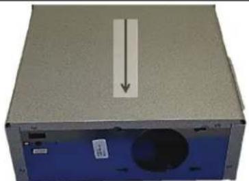
Using a 5/16" socket, remove the (4) screws from the bottom of each cooler to remove the wrappers.
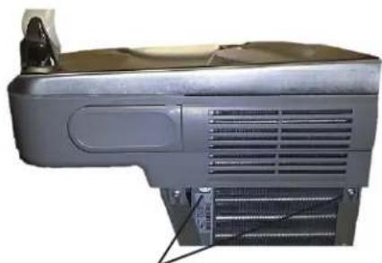
Using a #T20 (6 point star bit), loosen the shroud screws. Both sides, both coolers.
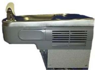
ONLY move the fi ller panel and j-clip to the refrigerated (right) side if right side will be mounted 'high'.
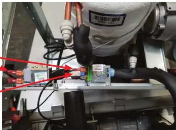
Refrigerated Cooler side:
Carefully lift and tip the shroud/basin assembly off of the cooler frame.
Only disconnect the (2) black wires coming from the shroud assembly that go to the solenoid valve and to the cold control.
Disconnect the water line at the solenoid valve. Reference (Fig. 15, Pg.17) for the operation of the quick connect fi ttings.
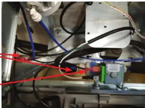
Non-Refrigerated Cooler side:
Carefully lift and tip the shroud/basin assembly off of the cooler frame.
Only disconnect the (2) black wires coming from the shroud assembly going to the solenoid valve and to the power cord.
Disconnect the water line at the solenoid valve. Reference (See Fig. 15, Pg.17) for the operation of the quick connect fi ttings.
INSTRUCTIONS CONTINUED.....
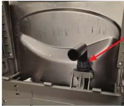
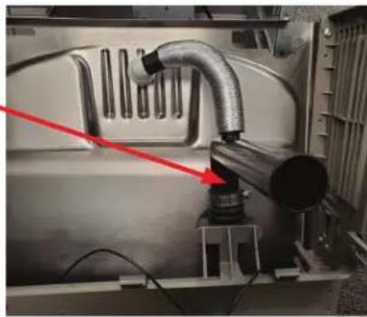
Swap drain parts in shroud:
- Loosen each hose clamp retaining the drain pieces.
Remove each drain piece and swap to other basin.
Tighten each hose clamp.
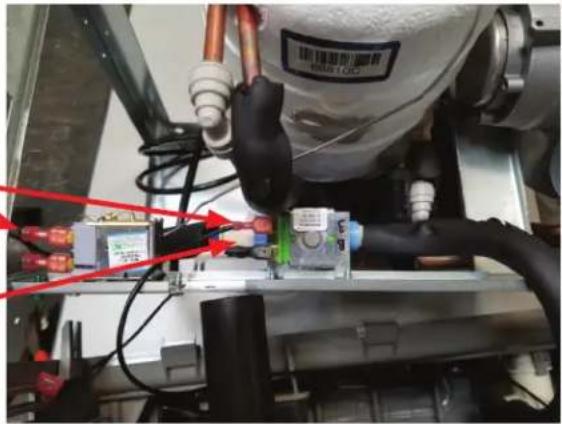
Refrigerated Cooler side:
Carefully lift and tip the shroud/basin assembly off of the cooler frame.
Only disconnect the (2) black wires coming from the shroud assembly that go to the solenoid valve and to the cold control.
Disconnect the water line at the solenoid valve. Reference (Fig. 15, Pg.17) for the operation of the quick connect fittings.
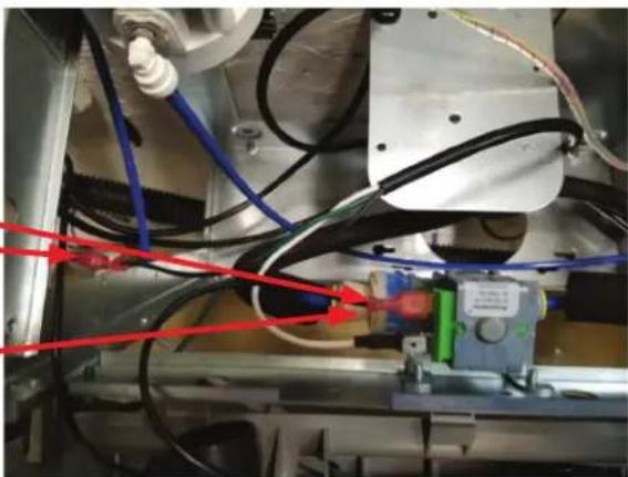
Non-Refrigerated Cooler side:
Carefully tip the shroud/basin assembly toward the cooler frame.
Connect one of the black wires to the solenoid valve and one to the power cord.
Re-connect the water line at the solenoid. Reference (See Fig. 15, Pg.17) for the operation of the quick connect fittings.
Precautions need to be taken when replacing the Basin/shroud assembly:
1) Make sure all wires are inside frames so as not to become pinched.
2) Water line coming from bottle filter drain must be pulled down as not to interfere with the fan operation. The fan blade needs to spin freely.
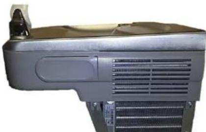
Using a #T20 (6 point star bit), tighten the shroud screws. Both sides, both coolers, being careful not to overtighten.
INSTALL WRAPPERS & TRIM STRIPS PER PAGE 13
SEE PAGE 14 FOR PLUMBING DIAGRAMS
Versatile Wrapper and Trim Kit Installation Instructions
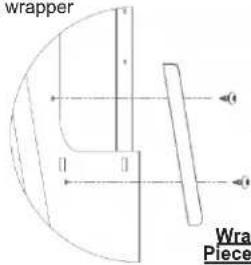
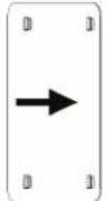
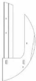
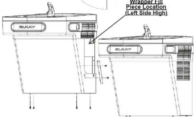
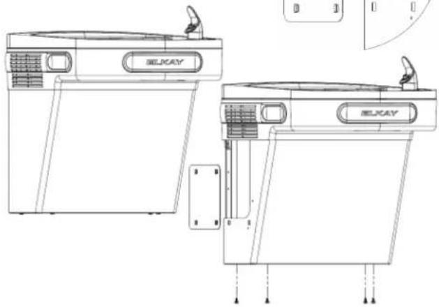
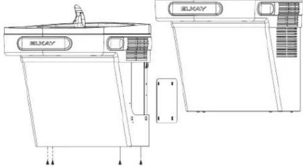
Left Hand Wrapper (High Side)
1) Remove existing wrapper by removing the (4) screws from bottom.
2) Screw trim piece to wrapper with (2) screws (provided)
3) Re-install wrapper with (4) screws.
4) Dispose of unused cover plate.
Right Hand Wrapper (Low Side)
1) Remove existing wrapper by removing the (4) screws from bottom.
2) Clip cover plate, sliding until plate sits flush with the wall.
3) Re-install wrapper with (4) screws.
4) Dispose of unused trim piece.
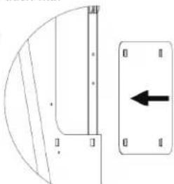
Left Hand Wrapper (Low Side)
1) Remove existing wrapper by removing the (4) screws from bottom.
2) Clip cover plate, sliding until plate sits flush with the wall.
3) Re-install wrapper with (4) screws.
4) Dispose of unused trim piece.
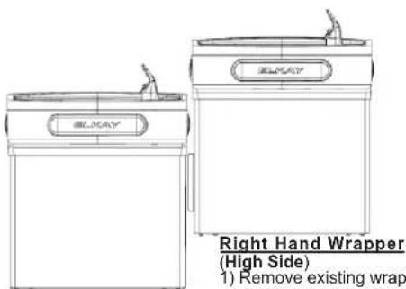
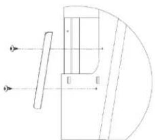
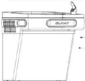
Right Hand Wrapper (High Side)
1) Remove existing wrapper by removing the (4) screws from bottom.
2) Screw trim piece to wrapper with (2) screws (provided)
3) Re-install wrapper with (4) screws.
4) Dispose of unused cover plate.

PLUMBING DIAGRAMS
VERSATILE BI-LEVEL
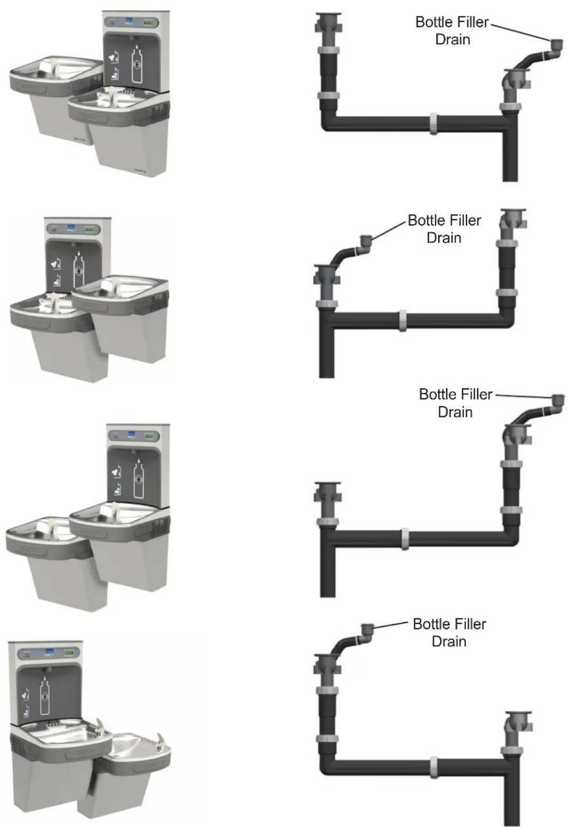
PLUMBING DIAGRAMS FOR EZ BI-LEVEL COOLERS
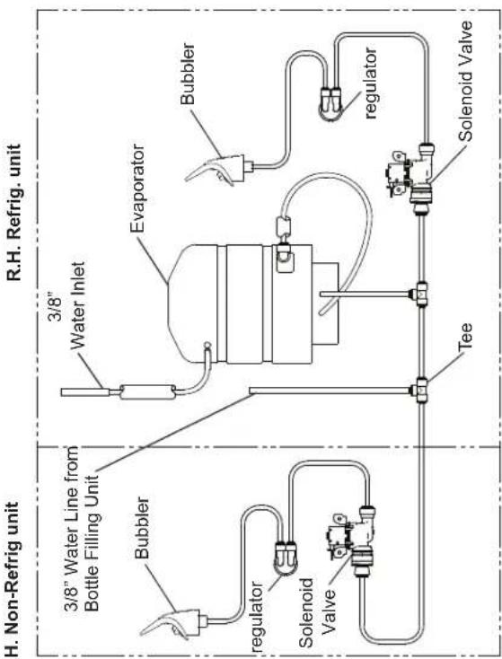
Standard EZ Bi-Level Pressurized Plumbing Diagram
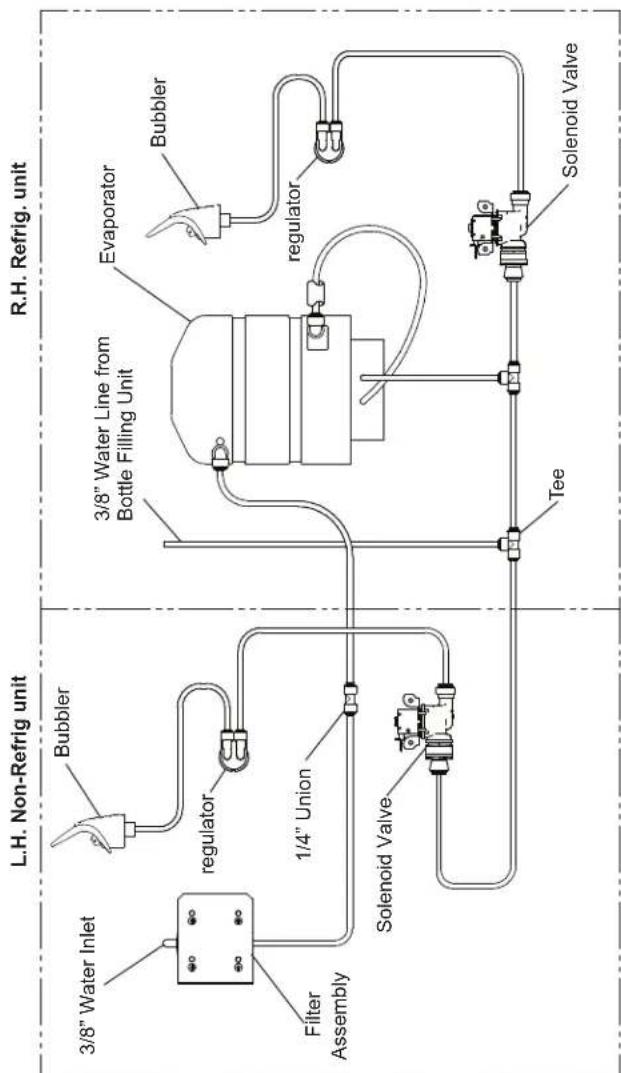
EZ Bi-Level Plumbing Diagram after Filter Installation & Bottle Filler Water Line Addition
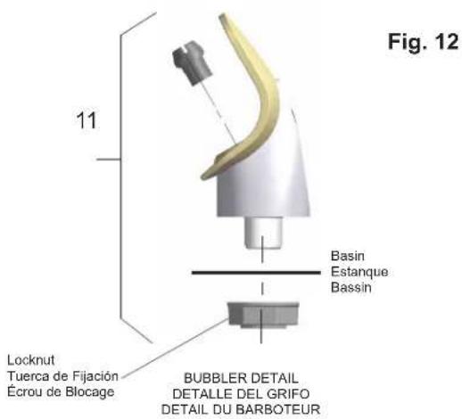
NOTE:
When installing replacement bubbler and pedestal, tighten nut only to hold parts snug in position. Do Not Overtighten.
NOTA:
Al instalar el grifo y pedestal de reemplazo, apriete la tuerca unicamente para mantener las piezas en una posicion adjustada. No dede apretarse demasiado.
REMARQUE:
Lors de L'installation du barboleur de remplacement ou du socle, serez la vis afi n de maintenir les éléments en place. No Pas Serrer Trop Fortement.
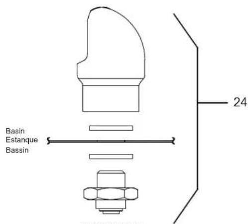
VR BUBBLER DETAIL
VR DETALLE DEL GRIFO
VR DETAIL DU BARBOTEUR
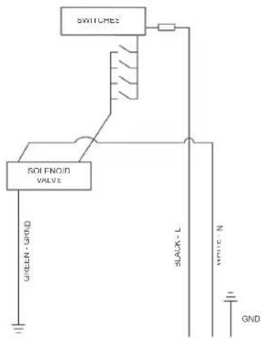
Fig. 13
115V Non-Refrigerated Wiring Diagram
Diagrama de cableado no refrigerados de 115 voltios
schéma de câblage non réfrigéré de 115 volts
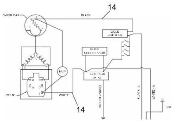
Fig. 14
115V Refrigerated Wiring Diagram
Diagrama de cableado refrigerados de 115 voltios
Schéma frigorifi que de 115 volts
220V PARTS LIST/ 220V LISTA DE PIEZAS/ 220V LISTE DES PIÈCES
| ITEM NO. | PART NO. | DESCRIPTION DESCRIPCIÓN | DESCRIPTION | |
| 10 | 1000004575 | Kit - Solenoid Valve/Regulator Assy | Kit - Montaje del Regulador/Válvula Soleoide | Kit - Solénoide de la Vanne/Régulateur |
| *4 | 1000002147 | Compressor Serv. Pak (220v/50Hz) | Compresor Paquete de servicio (220v/50Hz) | Kit d'Entretien du Compresseur (220v/50Hz) |
| 1000002146 | Compressor Serv. Pak (220v/60Hz) | Compresor Paquete de servicio (220v/60Hz) | Kit d'Entretien du Compresseur (220v/60Hz) | |
| 15 | 0000000245 | Kit - Fan Motor Assy/Blade/Motor/Shroud/Screws/Nut (220v-50Hz/60Hz) | Kit - Ventilador Motor Montaje/Hoja/Motor/Cubierta/Tornillos/Tuerca (220v-50Hz/60Hz) | Kit - Ventilateur Moteur Assemblée/Lame/Moteur/Cache/Vis/Ecrou (220v-50Hz/60Hz) |
| 20 | 98751C | Kit - /Relay/Cvr/Overload (220v/50Hz) | Kit - relé/sobrecarga/cubierta (220v/50Hz) | Kit-relais/surcharge/couverture (220v/50Hz) |
| 98752C | Kit - Relay/Cvr/Overload (220v/60Hz) | Kit - relé/sobrecarga/cubierta (220v/60Hz) | Kit-relais/surcharge/couverture (220v/60Hz) | |
| 29 | 36066C | Internal Power Cord | Cable de alimentación interno | Cordon d'Alimentation interne |
| 36067C | Internal Power Cord Non-Refrigerated | Cable de alimentación interno L/R | Cordon d'Alimentation interne L/R | |
| NS | 36004C | Jumper Wire | Puente de alambre | Fil de raccordement |
| NS | 28030C | Brkt - Power Inlet | Soporte - Entrada De Eléctrico | Support - Entrée d'alimentation |
| NS | 35826C | Inlet Power | Entrada De Eléctrico | Entrée d'alimentation |
| NS | 36357C | Split Snap Bushing | Buje rápido partido | Douille instantanée fendue |
| NS | 36300C | Jumper Wire (Yellow) | Cable - Puente (Amarillo) | Câble - Cavalier (Jaune) |
NS = NOT SHOWN
Fig.17
WATERSENTRY® PLUS Filter Detail Detalle WATERSENTRY® Filtro Description WATERSENTRY® Filtrage
| FILTER PARTS LIST | LISTA DE PIEZAS DEL FILTRO | LISTE DES PIÈCES DU FILTRE | ||
| ITEM NO. | PART NO. | DESCRIPTION | DESCRIPCIÓN | DESCRIPTION |
| 12 | 51300C0000000746 | Filter Assy-3000 Gal.Assy-Filter & Bracket includes Fltr Head/Mtg Bkt/John Guest Ftgs/Screws | Ensamblado del Filtro-3000 Galón Conjunto del Filtro y Soporte,Incluye Filtro Soporte/John Guest Guarniciones/Tomillos de Montaje de Cabeza | Ens. filtre-3000 GallonAssemblée-Filtre et Support InclutFiltre/Montage Support/John Guest/Vis à Têtê |
| ITEMNO. | PART NO. | DESCRIPTION DESCRIPCIÓN | DESCRIPTION | |
| 1 | 28401C | Hanger Bracket | Soporte Colgante | Support de Suspension |
| 2A | 55001109 | Basin - Stainless Steel | Estanque - Acero Inoxidable | Basin - Inox |
| 2B | 0000001337 | Basin - Stainless Steel (BF) | Estanque - Acero Inoxidable (BF) | Basin - Inox (BF) |
| 3 | 36216C | Wiring - Front/Side Push Bar | Barra de Empuje de Cableado-Frontal/Lateral | Barre Anti-Panique Câblage Avant/Côté |
| *4 | 36322C | Compr - Service Pak 115V | Compresor Paquete de Servicio 115V | Kit d'Entretien du Compresseur |
| 5 | 56092C | Tube - Poly (Cut To Length) | Tubo - Poli (Corte a la longitud) | Tube - Polyéthylène (Couper à la longueur) |
| 6 | 56229C | Assy - Shroud - Upper (Front Side Push) | Cubierta - Superior (Frontal Lateral Presión) | Enveloppe de Protection - Supérieure (Face Laterel Poussoir) Déshydrateur |
| 7 | 66703C | Drier | Secador | |
| 8A | 98900C | Kit - Drain Replacement EZTL8(Birkt, Tube, Flg, Clamp) | Kit - Reemplazo de Drenaje (EZTL8)/Soporte/Tubo/Guarnición de Tubo/Abrazadora | Kit - Remplacement de Drain (EZTL)/Support/Tube/Raccord de Tube/Bride Pour Tuyau |
| 8B | 97969C | Kit - Drain Replacement EZTLD (BF)(Birkt, Tube, Flg, Clamp) | Kit - Reemplazo de Drenaje (EZTLD)/Soporte/Tubo/Guarnición de Tubo/Abrazadora | Kit - Remplacement de Drain (EZTLD)/Support/Tube/Raccord de Tube/Bride Pour Tuyau |
| 9 | 55996C | In-Line Strainer | En Line Strainer | Filtre à eau en ligne |
| 10 | 1000004572 | Kit - Solenoid Valve/Regulator Assy | Kit - Montaje del Regulador/Válvula Solenoide | Kit - Solénoide de la Vanne/Régulateur |
| 11 | 56073C | Kit - Flexi Bubbler/O"Ring/Nut | Kit - Flexi Borboteador/Oring/Teourca | Kit - Flexi Barboteur/Oring/Noix |
| 12 | 98734C | Kit - Pushbar (Front/Side) EZSTL | Kit - Manillar (Frontal/Lateral) EZSTL | Kit - Barre de Poussée (Avant/Côté) EZSTL |
| 1000001600 | Kit - Pushbar (Front) EZTL | Kit - Manillar (Frontal) EZSTL | Kit - Barre de Poussée (Avant) EZSTL | |
| 13 | 98773C | Kit - Cold Control/Screws | Kit - Control del Enfriamiento/Tornillo | Kit - Contrôle de Refroidissement/Vis |
| 14 | 98774C | Kit - Internal Wiring/Pwr Cord/Black and White Jumper Wires | Kit - Cableado Interno/Cable/Negro Y Blanco Puente | Kit - Câblage Interne/Câble d'Alimentation/Noir et Fils de Raccordement Blanc |
| 15 | 98775C | Kit - Fan Motor Assy/Blade/Mtr/Shroud/Screws/Nut | Kit - Ventilador Motor Montaje/Hola/Motor/Cubierta/Tornillos/Tuerca | Kit - Ventilateur Moteur Assemblée/Lame/Moteur/Cache/Vis/Écrou |
| 16 | 98776C | Kit - Condenser/Drier | Kit - Condensador/Secador | Kit - Condenseur/Séchoir |
| 17 | 98777C | Kit- Compr Mtg Hdw/Grommets/Clips/Studs | Kit - Matériel de Montaje Compresor/Ojal/Pinza/Taquete | Kit - Montage du Compresseur materiel/Joint d'étanchéllé/Clip/Gouljon |
| 18 | 98778C | Kit - Heatx/Drier | Kit - Intercamblador Témikco/Secador | Kit - Echangeur Thermique/Déshydrateur |
| 19 | 98898C | Kit - Hardware (EZ) | Kit - Juego de Accesorios (EZ) | Kit - De Visserie (EZ) |
| 20 | 0000000238 | Kit - Relay/Overload/Cover | Kit - Relé/Sobrecarga/Cubierta | Kit - Relais/Surcharge/Relais Coiffe |
| 21 | 98724C | Kit - Evaporator Assembly | Montaje del Kit-Evaporador | Assemblée de L'évaporateur en Kit |
| 22 | 1000002062 | Kit - Tee 1/4" x 1/4" x 3/8" (3 Pack) | Kit - Tee 1/4" x 1/4" x 3/8" (Paquete de 3) | Kit - Tee 1/4" x 1/4" x 3/8" (Pack de 3) |
| 23 | 1000001602 | Kit - 75583C Elbow 5/16" x 1/4" (3 Pack) | Kit - 75583C Elbow 5/16" x 1/4" (Paquete de 3) | Kit - 75583C Elbow 5/16" x 1/4" (Pack de 3) |
| 24 | 97446C | Kit - Vandal Resistant Bubbler (VR) | Kit - Vandal Resistente polele (VR) | Kit - Vandal barbotur résistant (VR) |
| 25 | 1000001994 | Kit - 70682C 1/4" Tee (3 Pack) | Kit - 70682C 1/4" Tee (paquete de 3) | Kit - 70682C 1/4" Tee (Pack de 3) |
| 26 | 1000001812 | Kit - Bottle Filler Drain | Kit - de Drenaje de Llenada de la Botella | Kit - de Remplissage de Bouteille de Vidange |
| 27 | 1000004447 | Wasteline Drain Assy | Malgaste la Asamblea de la Linea EZTL(R) | Gaspiller TL (R) d'Assemblée de Ligne |
| 28 | 35980C | Power Cord Non-Refrigerated | Cable eléctrico L/R | Cordon d'Alimentation L/R |
| 36287C | Power Cord EZTL8 | Cable eléctrico EZTL8 | Cordon d'Alimentation EZTL8 | |
| 29 | 1000004564 | Kit - Regulator w/Holder & Nut | Kit - regulador con soporte y la tuerca | Kit - régulateur avec support et écrou |
| 30 | 0000001339 | Ferrule-Drain (Bottle Filler) | Férulá-Drenaje (Llenadora de botellas) | Virole-Drain (rempissure de bouteille) |
| NS | 1000000888 | Kit - EZTL Wrapper/Serv Label - Stainless (R) | Kit - envoltura de acero inoxidable (R) | Enveloppe extérieure kit-inox (R) |
| 1000000944 | Kit - EZTL Wrapper/Serv Label - Light Grey (R) | Kit de luz gris envoltura (R) | Kit-gris de Cape extérieure (R) | |
| NS | 1000000758 | Kit - EZTLD Wrapper/Serv Label - Stainless (L) | Envoltura exterior kit-acero inoxidable sin rejillas (L) | Acier inoxydable-kit Cape extérieure sans persiennes (L) |
| 1000000759 | Kit - EZTLD Wrapper/Serv Label - Light Grey (L) | Gris luz kit envoltura exterior sin rejillas (L) | Enveloppe extérieure kit-gris sans persiennes (L) | |
| NS = NOT SHOWN *INCLUDES RELAY & OVERLOAD. IF UNDER WAR-RANTY, REPLACE WITH SAME COMPRESSOR USED IN ORIGINAL ASSEMBLY.NOTE: All correspondence pertaining to any of the above water coolers or orders for repair parts MUST include Model No. and Serial No. of color, name and part number el número do modelo y número de serie del enfllador, el nombre y número de pieza de la pieza de repuesto. | ||||
| BOTTLE FILLER REPLACEMENT PART KITS | ||||
| ITEMNO. | PART NO. | DESCRIPTION DESCRIPCIÓN | DESCRIPTION | |
| NS | 98543C | Kit - Electrical Package 115V | Paquete Kit - Eléctrico 115V | Forfait Kit - Electriqueso 115V |
| NS | 98631C | Kit - Electrical Package 220V | Paquete Kit - Eléctrico 220V | Forfait Kit - Electriqueso 220V |
| NS | 98544C | Kit - IR Sensor | Sensor Kit - IR | Kit - Rcepteur IR |
| NS | 1000004573 | Kit - BF Solenoid Valve Replacement 115V | Reemplazo de la Válvula de Solenoide Kit 115V | Remplacement de la Valve Solénoide - Kit 115V |
| NS | 1000004574 | Kit - BF Solenoid Valve Replacement 220V | Reemplazo de la Válvula de Solenoide Kit 220V | Remplacement de la Valve Solénoide - Kit 220V |
| NS | 98546C | Kit - Aerator Replacement | Reemplazo Kit - Aireador | Remplacement du Kit - Aérateur |
| 31 | 98547C | Kit - Top Cover Replacement | Kit - Tapa Cubierta Reemplazo | Remplacement du Kit - Top Couvercle |
| 32 | 98549C | Kit - Hardware & Waterway Parts | Plezas del Kit - De Hardware y Por Vía Navegable | Pièces Kit - Matériel et Voie Navigable |
| NS | 98551C | Kit - Filter Mounting Cover | Cubierta del Filto de Kit - De Montaje | Couvercle de Filtre - Kit Montage |
| NS | 98552C | Kit - Retro Filter Mounting | Montaje de Filtro Kit - Retro | Montage de Retro - Kit Filtre |
| NS | 1000001813 | Kit - Tower/Basin Gasket | Kit - Torre/Cuenca Junta | Kit - Tour/Collecteur |
| NS = NOT SHOWN FOR PARTS, CONTACT YOUR LOCAL DISTRIBUTOR OR CALL 1.800.834.4816 PARA PIEZAS, CONTACTE A SU DISTRIBUIDOR LOCAL O LLAME AL 1.800.834.4816POUR OBTENIR DES PIÈCES, CONTACTEZ VOTRE DISTRIBUTEUR LOCAL OU COMPOSEZ LE 1.800.834.4816 | ||||
| PRINTED IN U.S.A.INPRESO EN LOS EE.UU.INPRIERE AUX E.C.U. REPAIR SERVICE INFORMATION TOLL FREE NUMBER 1.800.260.6640NÚMERO GRATIS DE SERVICIO 1.800.260.6640INFORMATIONS POUR LE SERVICE PAR NUMERO SANS FRAIS 1.800.260.6640ELKAY MANUFACTURING Co. • 1333 BUTTERFLIED ROAD SUITE 200 DOWNERS GROVE, IL 60515 USA - • 630.574.8484 • www.elkay.com | ||||

- REDUCE HEIGHT BY 3 INCHES FOR INSTALLATION OF CHILDREN'S ADA COOLER
- LEGEND/LEYENDA/LÉGENDE A - RECOMMENDED WATER S
- HANGER BRACKETS INSTALLATION
- INSTALLATION OF COOLER
- START UP
- ALSO SEE GENERAL INSTRUCTIONS
- CLEANING
- VIEW OF UNDERSIDE OF BASIN SHROUD
- SERVICE INSTRUCTIONS
- LOWER AND UPPER SHROUD
- BUBBLER
- SWITCHES BEHIND THE PUSH BAR
- BOTTLE FILLER INSTALLATION INSTRUCTIONS
- BF11 - BF12 PROGRAM
- SETTING THE CONTROL BOARD
- VERIFY CONTROL BOARD SOFTWARE
- ACCESSING THE PROGRAMMING BUTTON
- RESET THE FILTER MONITOR
- SETTING RANGE OF THE IR SENSOR WHERE APPLICABLE
- SETTING UNIT TYPE
- RESETTING BOTTLE COUNT
- SETTING FILTER CAPACITY
- REFRIGERATED COOLER SIDE
- NON-REFRIGERATED COOLER SIDE
- INSTRUCTIONS CONTINUED
- VERSATILE WRAPPER AND TRIM KIT INSTALLATION INSTRUCTIONS
- LEFT HAND WRAPPER (HIGH SIDE)
- RIGHT HAND WRAPPER (LOW SIDE)
- LEFT HAND WRAPPER (LOW SIDE)
- RIGHT HAND WRAPPER (HIGH SIDE)
Brand : Elkay
Model : EZOTL8WSLK
Category : Water fountain