
LKWRB1316SS - Water fountain Elkay - Free user manual and instructions
Find the device manual for free LKWRB1316SS Elkay in PDF.

| Product Type | Bi-Level Tubular Bottle Filler Fountain with Pet Fountain |
| Brand | Elkay |
| Model | LKWRB1316SS |
| Category | Water Fountain |
| Mounting Type | Wall-mounted on smooth, flat, finished surface |
| Water Supply Connection | 3/8" O.D. unplated copper tube |
| Drain Connection | 1-1/2" IPS |
| Inlet Water Pressure Range | 20-105 PSI |
| Stream Height Adjustment | Via screw access through push button; factory set at 35 PSI |
| Bubbler Type | Vandal-resistant bubbler |
| Bottle Filler Features | Includes drain pipe, aesthetic collar, and push button with nameplate |
| Pet Fountain Feature | Integrated pet fountain with dog bowl bubbler |
| Construction Materials | Lead-free connectors, plastic drain fittings to prevent electrolysis |
| Finish Options | Matte: Evergreen; Gloss: Beige, Gray, Terracotta, Black, Orange, White, Blue, Purple, Yellow, Brown, Red |
| Maintenance | Check for leaks, flush lines, adjust stream height, clean strainer |
| Safety Notes | Grounding of electrical equipment to water lines may cause electrolysis; use plastic drain fittings |
| Spare Parts Availability | Comprehensive parts list with item numbers; contact local distributor or technical services at 1.800.834.4816 |
| Compliance | ADA compliant (vandal-resistant bubbler) |
Frequently Asked Questions - LKWRB1316SS Elkay
User questions about LKWRB1316SS Elkay
0 question about this device. Answer the ones you know or ask your own.
Ask a new question about this device
Download the instructions for your Water fountain in PDF format for free! Find your manual LKWRB1316SS - Elkay and take your electronic device back in hand. On this page are published all the documents necessary for the use of your device. LKWRB1316SS by Elkay.
USER MANUAL LKWRB1316SS Elkay
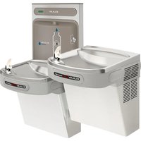
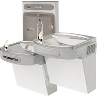
Bi-Level Tubular Bottle Filler Fountain with Pet fountain

natural_image
Technical line drawings of two identical water level fountains with no text or symbols4420BFDB Fountains are among the easiest to install Fountains on the market today. To assure you install these models easily and correctly, PLEASE READ THESE SIMPLE INSTRUCTIONS BEFORE STARTING THE INSTALLATION. CHECK YOUR INSTALLATION FOR COMPLIANCE WITH PLUMBING, ELECTRICAL, AND OTHER APPLICABLE CODES. After installation, leave these instructions with the Fountain for future reference.
INSTALLATION INSTRUCTIONS
IMPORTANT
ALL SERVICE TO BE PERFORMED BY AN AUTHORIZED SERVICE PERSON
IMPORTANT! INSTALLER PLEASE NOTE.
THE GROUNDING OF ELECTRICAL EQUIPMENT SUCH AS TELEPHONE, COMPUTERS, ETC. TO WATER LINES IS A COMMON PROCEDURE. THIS GROUNDING MAY BE IN THE BUILDING OR MAY OCCUR AWAY FROM THE BUILDING. THIS GROUNDING CAN CAUSE ELECTRICAL FEEDBACK INTO A FOUNTAIN, CREATING AN ELECTROLYSIS WHICH CAUSES A METALLIC TASTE OR AN INCREASE IN THE METAL CONTENT OF THE WATER. THIS CONDITION IS AVOIDABLE BY USING THE PROPER MATERIALS AS INDICATED. ANY DRAIN FITTINGS PROVIDED BY THE INSTALLER SHOULD BE MADE OF PLASTIC TO ELECTRICALLY ISOLATE THE FOUNTAIN FROM THE BUILDING PLUMBING SYSTEM.
- This fountain is to be mounted on a smooth, flat, finished surface with adequate support structure. NOTE: Mounting structure must be capable of supporting 300 lb. load on fountain.
- Refer to rough-in for plumbing.
- Install shut-off valve on water supply. (Valve not furnished)
- Locate and install fountain using 3/8" minimum fasteners. (Fasteners not furnished)
- Prior to installing the bottle filler to the center mounting position of fountain, insert the drain pipe (Item #15) by positioning the short end of drain pipe through mounting plate of bottle filler. Next, place the aesthetic collar (item # 29) onto the center mounting position of the fountain ensuring the vertical edge of the collar is upright and the curved edge sits below the mounting surface. Mount bottle filler to fountain with collar centered between the two pieces. Install bottle filler to fountain and secure with supplied hardware.
- Prior to installing the bottle filler to the arm mount of fountain, insert the drain pipe (Item #14) into the arm tunnel and adjust drain to lean to the left side of the arm when facing the button. Next, place the aesthetic collar (Item # 29) onto the arm mounting position of the fountain ensuring the vertical edge of the collar is upright and the curved edge sits below the mounting surface. Mount bottle filler to arm with collar centered between the two pieces. Install bottle filler to arm being sure drain tube is above mounting plate of filler. Install filler to fountain and secure with supplied hardware.
- Connect water supply and fountain drain. Connect drain waste "Tee" to fountain drain tubes. Connect outlet of "Tee" to drainage system. Water connection and drain must comply with local codes.
- Turn on water supply and check all connections for leaks.
CAUTION: This fountain is rated for inlet water pressure of 20-105 PSI. A pressure reducing regulator should be used if the inlet water supply exceeds 105 PSI. Any damage caused by reason of connecting this product to supply line pressures lower than 20 PSI or higher than 105 PSI is not covered by warranty.
- Water supply 3/8" O.D. unplated copper tube. Waste 1-1/2" IPS. Contractor to supply waste trap and service stop valve in accordance with local code.
- Connecting lines to be made of unplated copper and should be thoroughly flushed to remove all foreign matter before being connected to fountain. This fountain is manufactured in such a manner that it does not in any way cause taste, odor, color, or sediment problems.
- Connect fountain to supply line with a shut-off valve and install a 3/8" unplated copper water line between the valve and the fountain. Remove any burrs from outside of water line. Push the tubes straight into the fittings until they reach a positive stop, approximately 3/4" (See Fig. 3). DO NOT SOLDER TUBES INSERTED INTO PLASTIC FITTINGS AS DAMAGE TO THE O-RINGS MAY RESULT.


LEGEND
A = 3/8" O.D. UNPLATED COPPER TUBE CONNECT - SHUT OFF VALVE BY OTHERS
B = ACCESS PANEL ( 8" X 10" )
C = REMOVABLE BOTTOM COVER
4420BF1LDB

LEGEND
A = 3/8" O.D. UNPLATED COPPER TUBE CONNECT - SHUT OFF VALVE BY OTHERS
B = ACCESS PANEL (8" X 10")
C = REMOVABLE BOTTOM COVER
4420BF1UDB
* ADA REQUIREMENT


Vandal-Resistant Bubbler FIG. 1

TROUBLESHOOTING AND MAINTENANCE
ACTUATION OF QUICK CONNECT WATER FITTINGS:
Fountain is provided with lead-free connectors which utilize an o-ring water seal. To remove tubing from the fitting, relieve water pressure, push in on the gray collar while pulling on the tubing. (see Fig.2) To insert tubing, push tube straight into fitting until it reaches a positive stop, approximately 3/4".


ITEMIZED PARTS LIST
| ITEM NO. | PART NO. | DESCRIPTION |
| 1 | 28467C | Basin |
| 2 | 1000003814* | Cover - Round Plate |
| 3 | 40551C | Tailpipe |
| 4 | 0000000325 | Kit - Drain Plug/Gasket |
| 5 | 1000003812* | Access Panel |
| 6 | 1000003813* | Bottom Cover |
| 7 | 45926C | Drain Tube - 1-1/2" x 27-1/2" Lg. |
| 8 | 45724C | Tailpipe - 1-1/4" x 10"Lg. |
| 9 | 45726C | Drain Plug 1-1/2" (Dog Bowl) |
| 10 | 0000000466 | Kit - Bubbler (Dog Bowl) |
| 11 | 45931C | Plug - Drain (BF) |
| 12 | 55996C | In - Line Strainer |
| 13 | 66346C | Drain Tube |
| 14 | 66816C | Tube - Drain (Arm Only) |
| 15 | 66815C | Tube - Drain |
| 16 | 97446C | Kit - Bubbler (VR) |
| 17 | 101570540560 | Gasket |
| 18 | 75724C | Screw - 1/4"x20 x 3/4" LG. Pinned Torx |
| 19 | 97247C | Kit - VR Torx Screws/Bit |
| 20 | 98678C | Kit - 1.0 GPM Regulator (BF Only) |
| 98530C | Kit - | |
| 21 | 98679C | Kit - Nozzle |
| 22 | 98680C | Kit - Aerator/Key |
| 23 | 98681C | Kit - Blank Bottle Filler Trim |
| 1000003692 | Kit - LK4420BFDB Bottle Filler Trim | |
| 1000003693 | Kit - 4420BFDB Bottle Filler Trim | |
| 24 | 98682C | Kit - Push Button w/Blank Nameplate |
| 1000003694 | Kit - Push Button w/LK4420BFDB Nameplate | |
| 1000003695 | Kit - Push Button w/4420BFDB Nameplate | |
| 25 | 98683C | Kit - Plastic Drain |
| 26 | 98684C | Kit - 90° Plastic Drain |
| 27 | 98685C | Kit - 4400 Series Hardware |
| 28 | 98686C | Kit - Bottle Filler Waterway |
| 29 | 1000005456 | Aesthetic Collar |
| NS | 1000003490 | Drain Tube (Not Shown) |
NS = Not Shown
*select color option to complete part number

FIG. 4
STREAM HEIGHT ADJUSTMENT:
Stream height is factory set at 35 PSI. If supply pressure varies greatly from this, insert a small straight bladed screwdriver through the access hole in the center of the push button and turn the adjustment screw. Clockwise adjustment will raise the stream and counterclockwise adjustment will lower the stream. For best adjustment, the stream should be approximately 1 1/2" above the top of the bubbler. (See Fig. 4)

*FINISH COLOR OPTIONS – Choose color option to
complete your model number, add as suffix example:
4420BF1UDBEVG
Matte finish: □ Evergreen = EVG
Gloss finish:
□ Beige = BGE □ Gray = GRY □ Terracotta = TER
Black = BLK Orange = ORN White = WHT □
□ Blue = BLU □ Purple = PUR □ Yellow = YLW
Brown = BRN Red = RED
PRINTED IN U.S.A.
Halsey Taylor – halseytaylor.com
Elkay – elkay.com
FOR PARTS CONTACT YOUR LOCAL DISTRIBUTOR OR CALL TECHNICAL SERVICES AT 1.800.834.4816
1333, BUTTERFIELD ROAD, DOWNERS GROVE, ILLINOIS 60515

Brand : Elkay
Model : LKWRB1316SS
Category : Water fountain