
H-10243 - Office Uline - Free user manual and instructions
Find the device manual for free H-10243 Uline in PDF.

User questions about H-10243 Uline
0 question about this device. Answer the ones you know or ask your own.
Ask a new question about this device
Download the instructions for your Office in PDF format for free! Find your manual H-10243 - Uline and take your electronic device back in hand. On this page are published all the documents necessary for the use of your device. H-10243 by Uline.
USER MANUAL H-10243 Uline
natural_image
Line drawing of a simple wooden table with two legs and supports (no text or symbols)TOOLS NEEDED
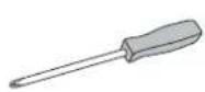
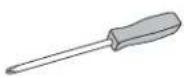
Phillips Head
Screwdriver
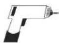
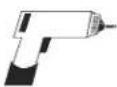
Drill
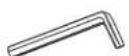
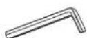
Allen Wrench (included)

Two Person Assembly Recommended
ASSEMBLY

NOTE: Count and inspect all pieces before disposing of any carton or packing materials.
| # DESCRIPTION QTY | |
| 1 Channel 1 | |
| 2 Leg 2 | |
| 3 Leg Screw, 6 x 12 mm 16 | |
| 4 Side Frame 2 | |
| 5 Tabletop 1 | |
| 6 Wood Screw, 4.8 x 16 mm | 18 |
| 7 Lever | 1 |
| 8 Foot | 2 |
| 9 Foot Screw, 8 x 65 mm | 8 |
| 10 Glide | 4 |
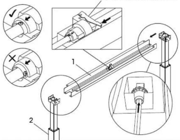
Figure 2
Center Mechanism Lever
text_image
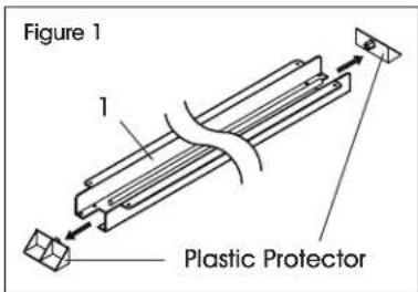
Technical diagram showing mechanical assembly with labeled components and directional arrows indicating motion or movement.- Remove the two plastic protectors on the sides of the channel (1). (See Figure 1)
text_image
Figure 1 1 Plastic Protector- For easier assembly, place channel (1) on a raised surface, such as a table. Insert metal rod located inside of channel (1) into the mechanism opening on the top of the leg (2). Repeat this step on the opposite side. (See Figure 2)

NOTE: If it is difficult to insert the rod into the mechanism opening on the top of the leg:
- Align the arrow on the mechanism with the screw. If metal rod will not insert into mechanism opening on top of leg, press center mechanism lever and rotate metal rod to align arrow with screw on top of metal rod. (See Figure 2)
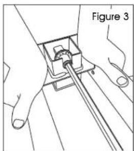
- If still experiencing difficulty inserting the rod into the mechanism opening, slowly press down on top of leg to turn mechanism opening. As opening turns, push rod into opening until it is inserted fully. (See Figure 3)
natural_image
Line drawing of hands holding a mechanical component, labeled 'Figure 3' (no text or symbols on the diagram itself)ASSEMBLY CONTINUED
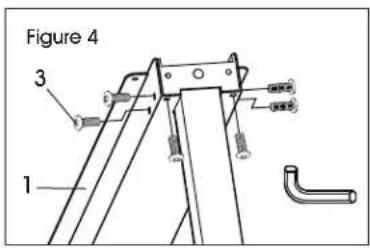
- Insert six leg screws (3) into the sides and underside of the channel (1). Tighten using the Allen wrench. Repeat on opposite side. (See Figure 4)
text_image
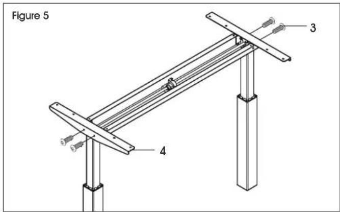
Figure 4 3 1- Attach the side frames (4) to each end of channel using four leg screws (3). Tighten with the Allen wrench. (See Figure 5)
text_image
Figure 5 3 4- Place the tabletop (5) upside down on a clean, smooth, non-marring surface to prevent scratching.
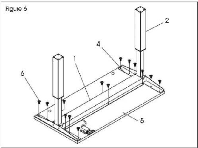
- Place frame on tabletop (5). Adjust position of frame so that it is centered on the tabletop. (See Figure 6)

NOTE: Frame is designed to fit tabletops that are 24" or 30" wide. For 30" wide tabletops, side frames will be approximately 3" from front and back edges of tabletop. Figure 6 shows a 24" tabletop (5).

NOTE: Lever (7) should be on front of tabletop, opposite of the two grommet holes. Back of tabletop has two grommet holes. Front of tabletop is the opposite side.
- Attach the side frames (4) and the channel (1) to tabletop (5) using the drill and 14 wood screws (6). (See Figure 6)

NOTE: Tabletop does not include pre-drilled holes. Drill wood screws directly into tabletop to attach base.
text_image
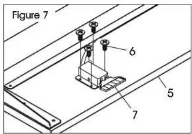
Figure 6 1 2 4 5 6- Place lever (7) so that the handle is flush with the front edge of table top (5). Attach using the drill and four wood screws (6). (See Figure 7)
text_image
Figure 7 6 5 7
NOTE: The lever will be located on the right side of the table when flipped onto its feet.
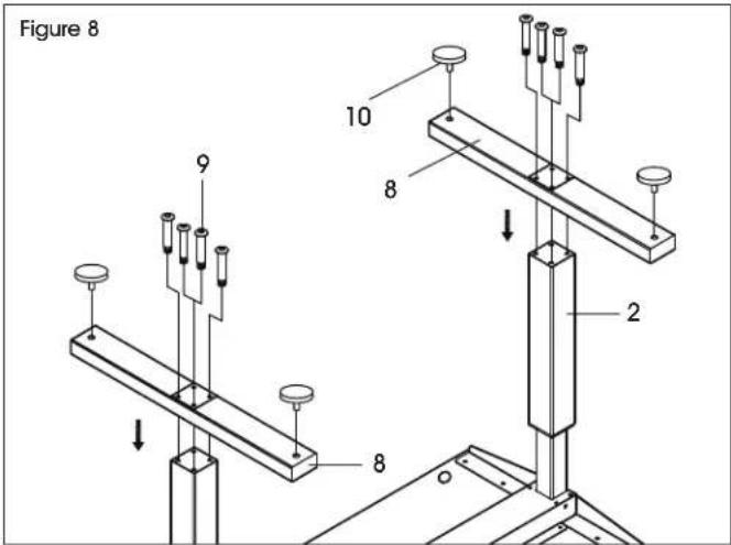
- Attach foot (8) to leg (2) using four foot screws (9). Tighten using Allen wrench. Repeat on opposite side. (See Figure 8)
- Insert glides (10) into holes on bottom of feet (8). (See Figure 8)
text_image
Figure 8 9 10 8 2 8ASSEMBLY CONTINUED
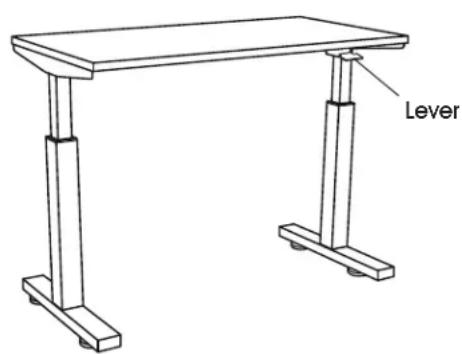
Figure 9
text_image
Lever- Table is now fully assembled. With second person, carefully flip the table onto its feet. (See Figure 9)
OPERATION
PNEUMATIC HEIGHT ADJUSTMENT
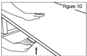
- When raising/lowering table, use one hand to support the center of top and the other hand to lift lever. (See Figure 10)
- To raise table height, lift lever. Table will move up gradually. Release lever when desired height is reached.
- To lower table, lift lever and with one hand push the center of the tabletop downward. Release lever when desired height is reached.
text_image
Figure 10TROUBLESHOOTING
| OPERATING ISSUE RECOMMENDATIONS | |
| Legs are unusually noisy. The table has two-stage legs that produce more noise when one leg extends into the other.To reduce noise, apply silicon lubricant to legs. | |
| Rod will not fit into leg mechanism. Slowly press down on top of leg to turn mechanism opening. As opening turns, push rod into opening until it is inserted fully.Two or three person assembly is highly recommended. |

H-10242, H-10243,
H-10244
ESCRITORIO DE ALTURA AJUSTABLE NEUMÁTICO
800-295-5510
uline.mx
natural_image
Line drawing of a two-legged table with support legs (no text or symbols)ENSAMBLE

text_image
Technical diagram showing mechanical assembly with labeled components and directional arrows indicating motion or movement.
natural_image
Line drawing of a two-legged table with support legs (no text or symbols)OUTILS REQUIS
Tournevis cruciforme
Perceuse
Clé Allen (inclus)
text_image
Technical diagram showing mechanical assembly with labeled components and directional arrows indicating motion or movement.
natural_image
Line drawing of hands holding a mechanical component, labeled 'Figure 3' (no text or symbols on the diagram itself)MONTAGE SUITE
text_image
Figure 4 1 3text_image
Figure 5 3 4text_image
Figure 7 6 5 7


