
H-10217 - Office Uline - Free user manual and instructions
Find the device manual for free H-10217 Uline in PDF.

User questions about H-10217 Uline
0 question about this device. Answer the ones you know or ask your own.
Ask a new question about this device
Download the instructions for your Office in PDF format for free! Find your manual H-10217 - Uline and take your electronic device back in hand. On this page are published all the documents necessary for the use of your device. H-10217 by Uline.
USER MANUAL H-10217 Uline
natural_image
Line drawing of a simple office desk with adjustable legs and wheels (no text or symbols)TOOLS NEEDED
Phillips
Screwdriver
4 Allen Wrench
6 Allen Wrench
(included)
Open-End Wrench (included)

Two Person Assembly Recommended
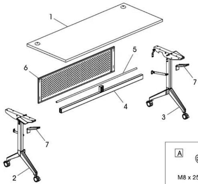
PARTS
text_image
1 2 3 4 5 6 7 A M8 x 25PARTS
| # DESCRIPTION QTY. | |
| 1 Tabletop 1 | |
| 2 Left Frame Leg 1 | |
| 3 Right Frame Leg 1 | |
| 4 Support Bar 1 | |
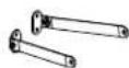
| 5 Hexagonal Drive Rod 1 | |
| 6 Modesty Panel | 1 |
| 7 Plastic Cover | 2 |
Hardware Kit

CAUTION! Some parts may have sharp edges. Care must be taken when handling various pieces to avoid injury. For your safety, wear a pair of work gloves when assembling.


M8 x 25 mm Bolt x 4


Lower Modesty Panel Connector x 2
Upper Modesty Panel Connector x 2


M6 x 8 mm Bolt x 8


M6 x 30 mm Hexagon Bolt x 2


M6 x 28 mm Hexagon Bolt x 2

Hole Cover x 2


Top Support Block x 1


M6 x 16 mm Bolt x 4


M6 x 15 mm Bolt x 8

Ganging Bracket x 4


ST3.5 x 35 mm Wood Screw x 16


Black Grommet x 2


Silver Grommet x 2
ASSEMBLY

NOTE: Count and inspect all pieces before disposing of any carton or packing materials.

NOTE: Assemble on a smooth, non-marring surface to avoid scratching.
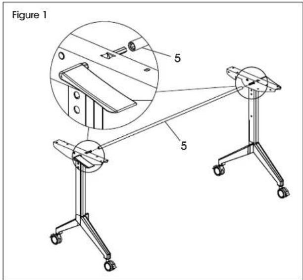
- With a second person, attach hexagonal drive rod (5) to the top bracket between left and right legs. (See Figure 1)
text_image
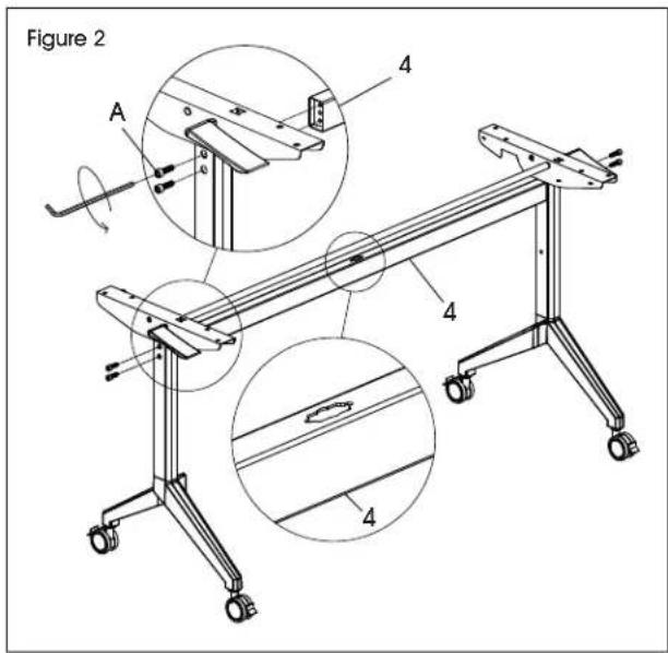
Figure 1 5 5- Install support bar (4) between left and right legs using four M8 x 25 mm bolts (A). Tighten using #6 Allen wrench. (See Figure 2)

NOTE: Ensure opening in middle of support bar is facing up.
text_image
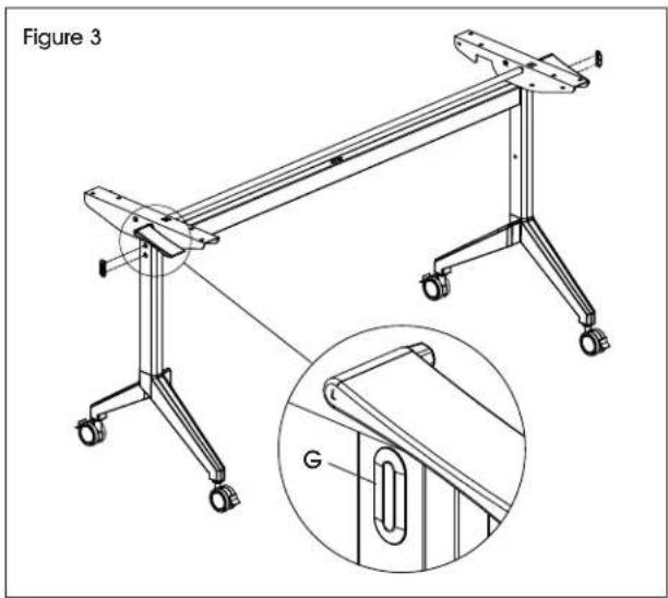
Figure 2 A 4 4 4- Install hole covers (G) into side of each leg. (See Figure 3)
natural_image
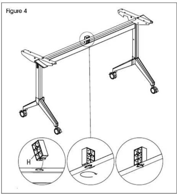
Technical line drawing of a mechanical frame assembly with an inset showing a magnified detail (no text or symbols)- Insert top support block (H) into opening in support bar (4). Rotate to lock in place. (See Figure 4)
text_image
Figure 4 HASSEMBLY CONTINUED
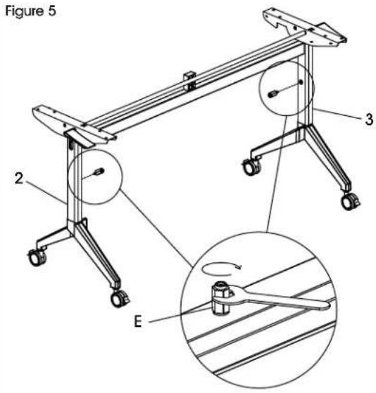
- Install one M6 x 30 mm hexagon bolt (E) into the middle section of each leg frame. Tighten using open-end wrench. (See Figure 5)
text_image
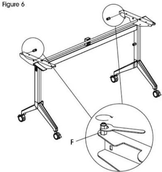
Figure 5 2 3 E- Install one M6 x 28 mm hexagon bolt (F) into the top of each leg. Tighten using open-end wrench. (See Figure 6)
text_image
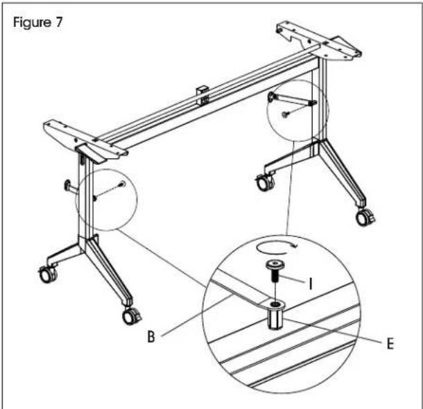
Figure 6 F- Align the narrow end of one lower modesty panel connector (B) with the M6 x 30 mm hexagon bolt (E) attached to the frame leg. Attach using one M6 x 16 mm bolt (I) and tighten using #4 Allen wrench. Repeat on opposite leg. (See Figure 7)
text_image
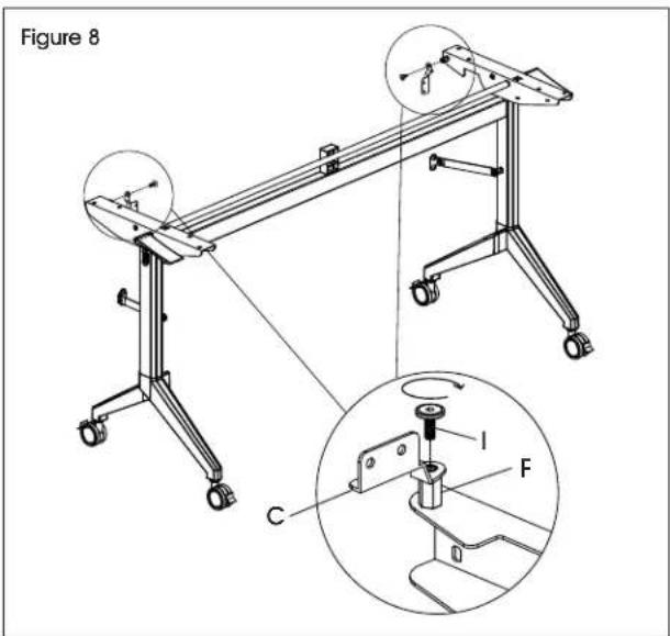
Figure 7 B I E- Align the narrow end of one upper modesty panel connector (C) with the M6 x 28 mm hexagon bolt (F) attached to the top of the leg frame. Attach using one M6 x 16 mm bolt (I) and tighten using #4 Allen wrench. Repeat on opposite leg frame. (See Figure 8)
text_image
Figure 8 C I FASSEMBLY CONTINUED
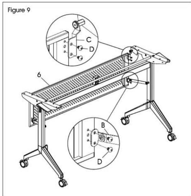
- Attach modesty panel (6) to lower and upper modesty panel connectors (B, C) using eight M6 x 8 mm bolts (D). Tighten using #4 Allen wrench. (See Figure 9)
text_image
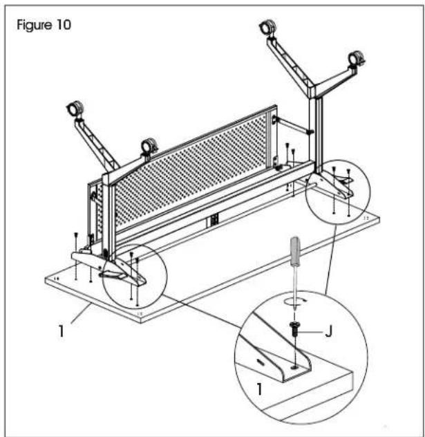
Figure 9 6 C D B D- With a second person, place tabletop (1) upside down with holes facing up. Carefully flip and align assembled frame with pre-drilled holes in tabletop. Install using eight M6 x 15 mm bolts (J) and Phillips screwdriver. (See Figure 10)
text_image
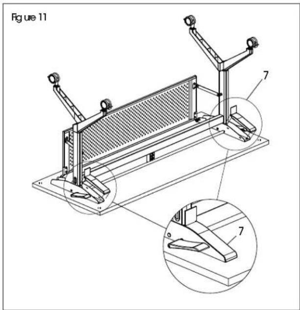
Figure 10 1 J 1- Insert one plastic cover (7) into each bracket. With second person, carefully flip assembled table upright. (See Figure 11) Insert black or silver grommets depending on preference.
text_image
Figure 11 7 7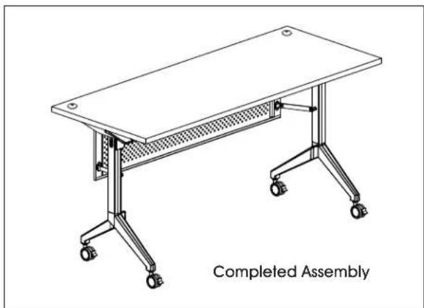
natural_image
Line drawing of a completed assembly table with wheels and a handle (no text or symbols on the table itself)JOINING TABLES WITH GANGING BRACKETS

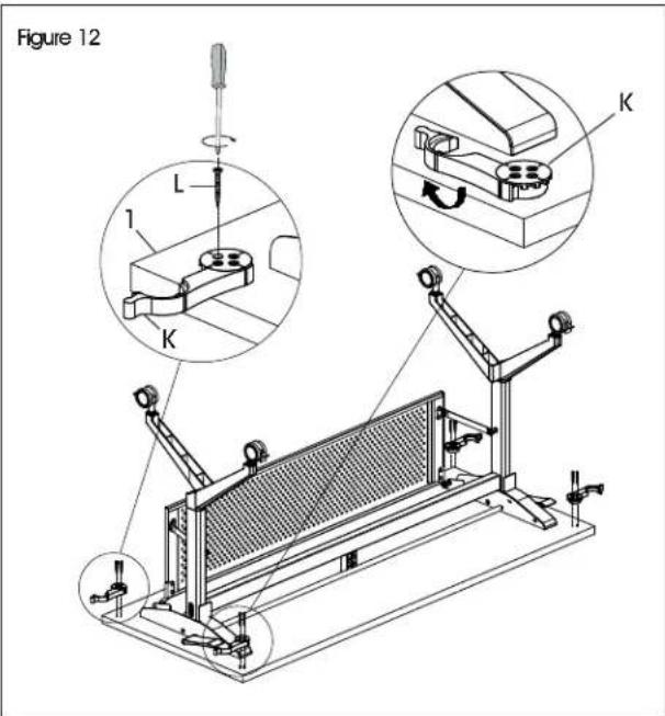
NOTE: Each training table includes two sets of ganging brackets (K). Each ganging bracket set consists of two hooks.
- With a second person, place assembled table upside down with holes facing up.
- On one side of the tabletop, install two hooks in the pre-drilled holes located on each corner using eight ST3.5 x 35 mm wood screws (L). Tighten using Phillips screwdriver. Repeat on opposite side. (See Figure 12)
- Repeat steps 1-2 on remaining table(s). (See Figure 12)
- Move tables together and connect using ganging brackets. (See Figure 13)
text_image
Figure 12 L 1 K K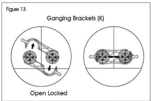
text_image
Figure 13 Ganging Brackets (K) Open Locked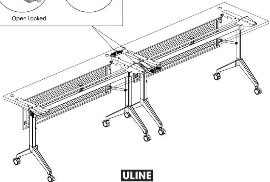
text_image
Open Locked ULINEULINE H-10216, H-10217
COLECCIÓN URBANA
natural_image
Line drawing of a conference table with four legs and a side table, no text or symbols presentnatural_image
Mechanical linkage diagram showing two connected components with directional arrows (no text or labels)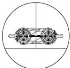
natural_image
Pure mechanical diagram showing two circular components with internal shafts and housing (no text or symbols)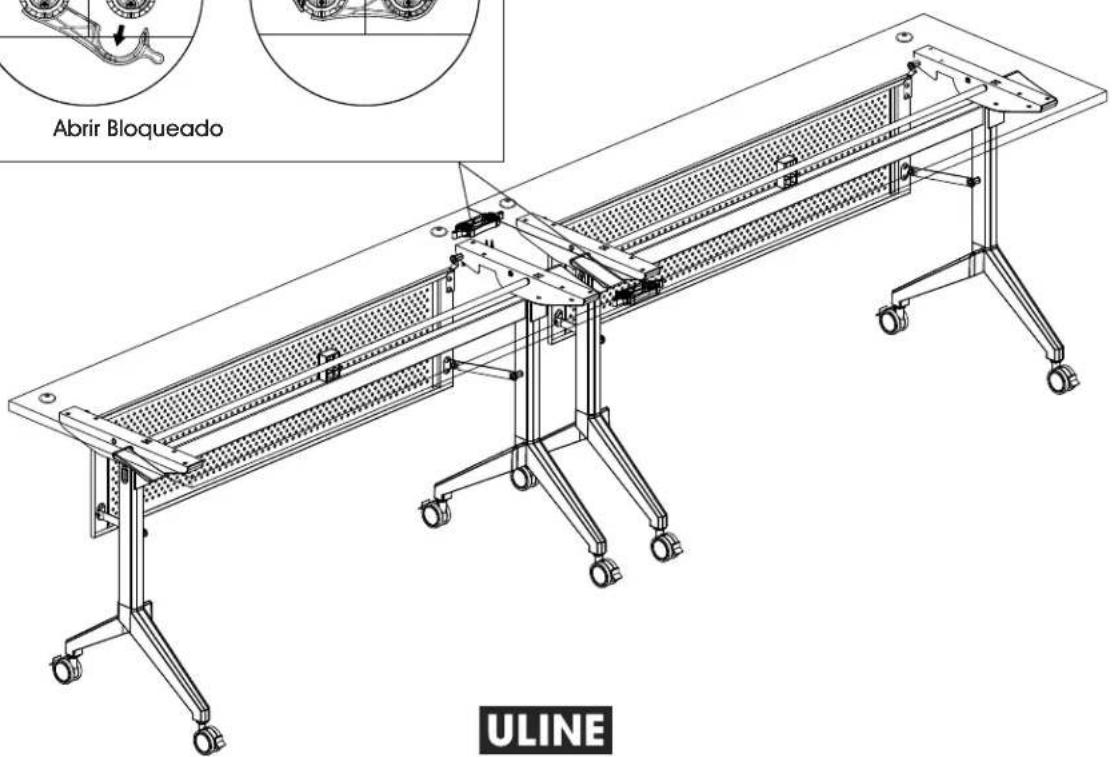
natural_image
Line drawing of a conference table with wheels and a perforated panel (no text or symbols)OUTILS REQUIS
Tournevis cruciforme
text_image
Technical diagram of a folding table with labeled components, including panel, grating, and support structures.
text_image
Figure 1 5 5natural_image
Technical line drawing of a mechanical frame assembly with an inset magnified detail showing a component labeled 'G' (no text or symbols present)text_image
Figure 5 2 3 Etext_image
Figure 6 Ftext_image
Figure 7 A B E Itext_image
Figure 8 C I FMONTAGE SUITE
text_image
Figure 8 1 J 1text_image
Figure 11 7 7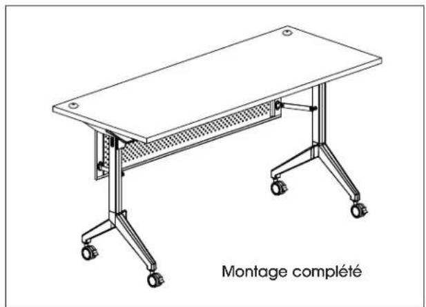
text_image
Figure 12 L 1 K Knatural_image
Mechanical linkage diagram showing two interlocking gears with directional arrows (no text or labels)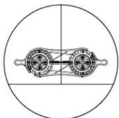
natural_image
Pure mechanical diagram showing two rotating components within a circle (no text or symbols)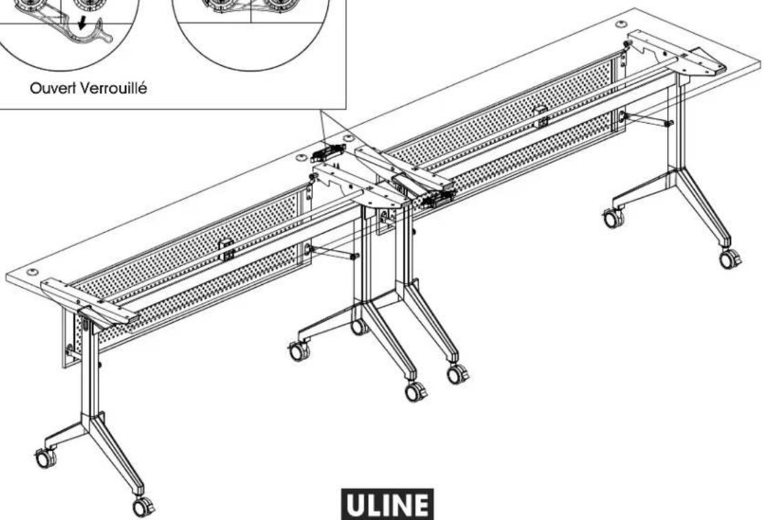
text_image
Ouvert Verrouillé ULINEULINE
1 800 295-5510
uline.ca


