H-11062 - Fan Uline - Free user manual and instructions
Find the device manual for free H-11062 Uline in PDF.

User questions about H-11062 Uline
0 question about this device. Answer the ones you know or ask your own.
Ask a new question about this device
Download the instructions for your Fan in PDF format for free! Find your manual H-11062 - Uline and take your electronic device back in hand. On this page are published all the documents necessary for the use of your device. H-11062 by Uline.
USER MANUAL H-11062 Uline
TOOLS NEEDED
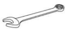
10 mm Wrench
11 mm Wrench
13 mm Wrench
16 mm Wrench
19 mm Wrench
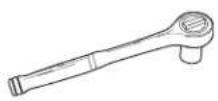

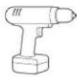
Socket Wrench 24 mm Socket Drill 5/16" Nut Driver Bit
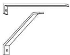
WALL BRACKET PARTS
natural_image
Technical line drawing of two metal beams with mounting holes (no text or symbols)Bracket Assembly x 1
text_image
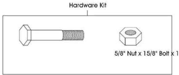
Hardware Kit 5/8" Nut x 15/8" Bolt x 1WALL BRACKET ASSEMBLY

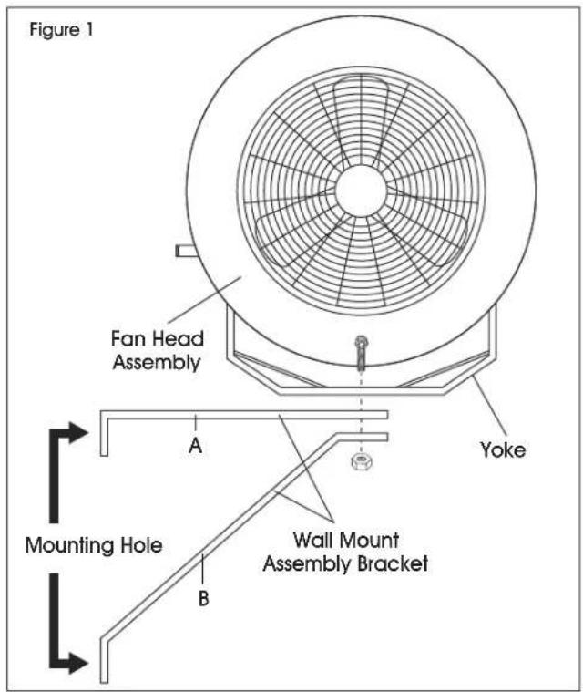
NOTE: Fan can be placed above the wall mount assembly or hung down below.
- Secure part A of wall mount assembly bracket to solid surface from which fan will be hung. A single mounting hole is located on part A. Secure to surface using a wall anchor (not included). (See Figure 1)
- Position part B under A and situate B so that A is level. A single mounting hole is located on part B. Secure part B to surface using a wall anchor (not included). (See Figure 1)
- Using a 16 mm wrench, secure the yoke to wall mount assembly bracket by inserting the 5/8" bolt through the center hole in the yoke and through the holes in both parts of the wall mount assembly bracket. (See Figure 1)

NOTE: The yoke may open up or down depending on which way the wall mount assembly bracket is hung. Ensure assembly is level and stable.

NOTE: A safety chain (not included) is recommended for securing fan head.
text_image
Figure 1 Fan Head Assembly A Yoke Mounting Hole B Wall Mount Assembly BracketMOBILE PEDESTAL PARTS
natural_image
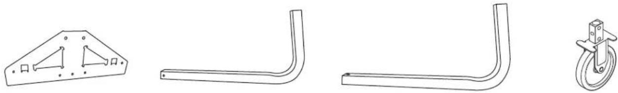
Technical line drawings of four mechanical components: a bracket, a bent rod, a roller, and a wheel (no text or symbols present)Bracket x 2 Floor Mount Stand x 2 Upright Mount x 1 Caster x 2
Hardware Kit
text_image
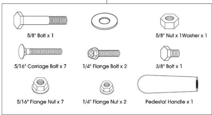
5/8" Bolt x 1 5/8" Nut x 1 Washer x 1 5/16" Carriage Bolt x 7 1/4" Flange Bolt x 2 3/8" Bolt x 1 5/16" Flange Nut x 7 1/4" Flange Nut x 2 Pedestal Handle x 1MOBILE PEDESTAL ASSEMBLY
- Insert caster into slots at the ends of bracket. Secure with one 1/4" flange bolt and one 1/4" flange nut per caster. Tighten with 10 and 11 mm wrenches (See Figure 2)
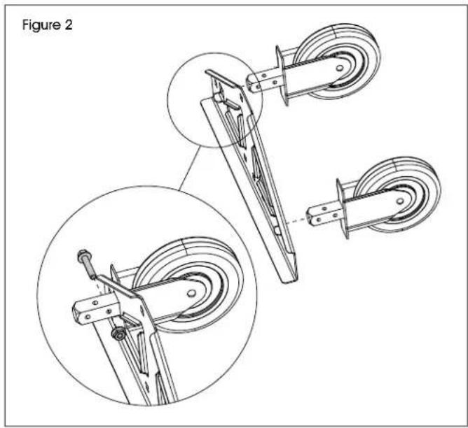
natural_image
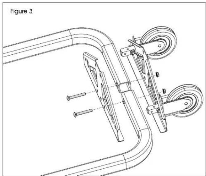
Technical line drawing of a mechanical device with two views (top and side), showing components like wheels and levers (no text or symbols)- Insert two 5/16" carriage bolts through inner holes on bracket, floor mount stands and bracket with casters. Secure with 5/16" flange nuts (See Figure 3)

NOTE: Do not fully tighten nuts until step 4 is complete.
natural_image
Technical line drawing of a mechanical device with pulleys and screws, labeled Figure 3 (no text or symbols on the diagram itself)MOBILE PEDESTAL ASSEMBLY CONTINUED
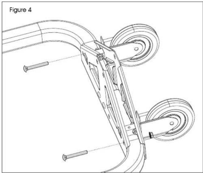
- Insert 5/16" carriage bolts through holes on ends of brackets. Secure with 5/16" flange nuts. (See Figure 4)
natural_image
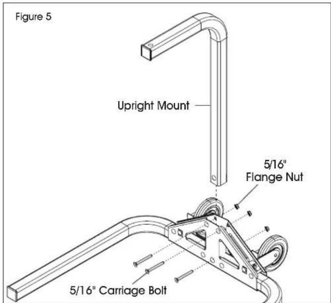
Technical line drawing of a mechanical device with pulleys and screws, labeled as Figure 4 (no text or symbols on the diagram itself)- Insert upright mount into top opening of the brackets. Secure using one 5/16" carriage bolt and 5/16 flange nut through bottom middle hole. Use two 5/16" carriage bolts and flange nuts through remaining square holes at top of brackets. (See Figure 5)
text_image
Figure 5 Upright Mount 5/16" Flange Nut 5/16" Carriage Bolt-
Tighten all nuts with 13 mm wrench.
-
Attach yoke to upright mount with 5/8" bolt through center hole on yoke, washer and pedestal. Secure with 5/8" nut. Tighten with 24 mm socket wrench. (See Figure 6)
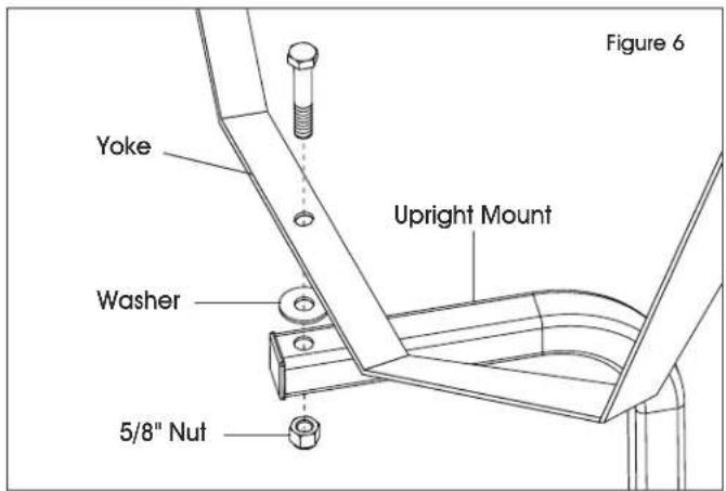
text_image
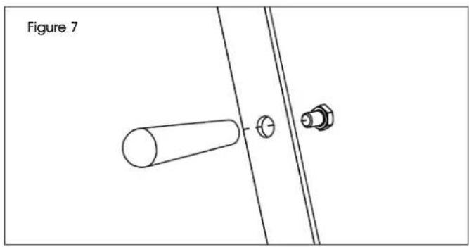
Figure 6 Yoke Upright Mount Washer 5/8" Nut- Attach pedestal handle to outside of yoke with 3/8" bolt through side hole on yoke. Tighten with 16 mm wrench. (See Figure 7)
natural_image
Technical line drawing of a mechanical assembly with a cylindrical component and two bolts, labeled Figure 7 (no text or symbols on the diagram itself)DOCK ARM PARTS
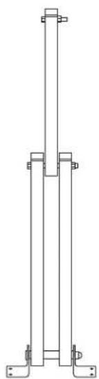
natural_image
Pure technical line drawing of a vertical support structure without any text, numbers, or symbolsDock Arm x 1
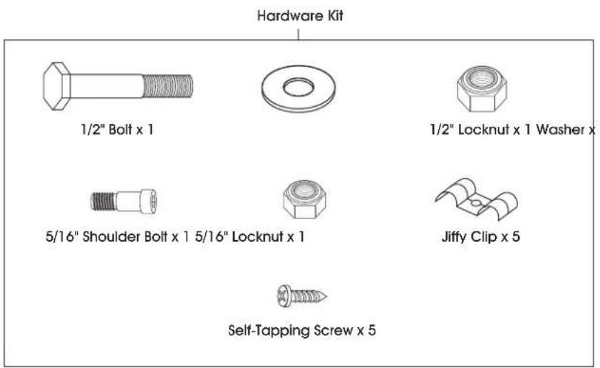
text_image
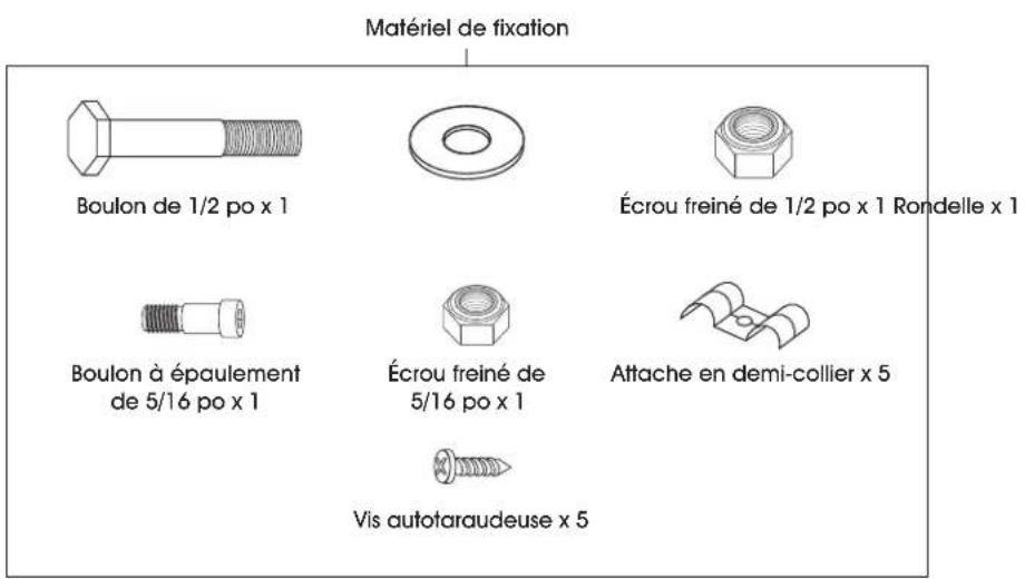
Hardware Kit 1/2" Bolt x 1 1/2" Locknut x 1 Washer x 5/16" Shoulder Bolt x 1 5/16" Locknut x 1 Jiffy Clip x 5 Self-Tapping Screw x 5DOCK ARM ASSEMBLY
MOUNTING HARDWARE
The hardware to attach the fan mount to the support structure is not supplied. Hardware must be adequately sized and be the proper type for installation to safely support the fan. Always follow the fastener manufacturer's installation instructions.
- Secure dock arm mounting bracket to solid surface from which fan will be hung. Mounting holes are in each corner of mounting bracket. Secure to surface using suitable hardware (not included). (See Figure 8)
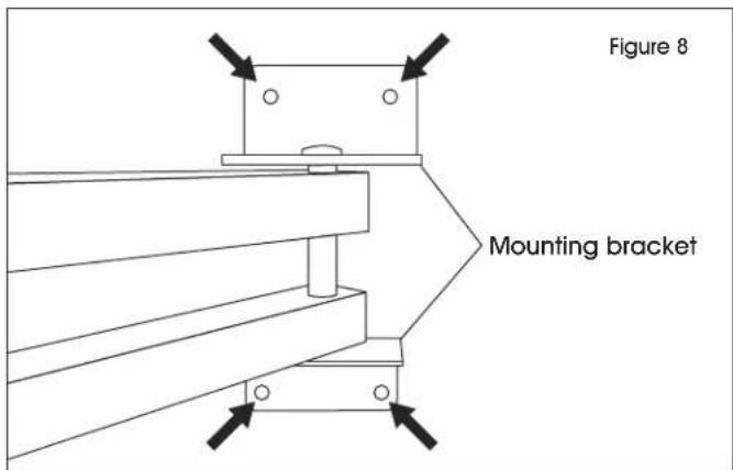
text_image
Figure 8 Mounting bracket- Secure the yoke to dock arm by inserting the 1/2" bolt through the hole in the dock arm and the center hole in the yoke. Insert washer onto 1/2" bolt prior to yoke. Secure with 1/2" locknut and tighten using 19 mm wrench. (See Figure 9)
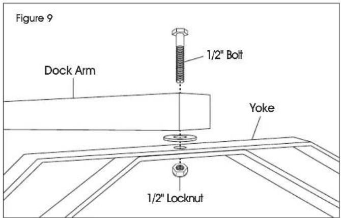
text_image
Figure 9 Dock Arm 1/2" Bolt Yoke 1/2" LocknutDOCK ARM ASSEMBLY CONTINUED
SECURE POWER CORD
- Secure fan power cord to dock arm with jiffy clips over the power cord. Align jiffy clips with pre-drilled holes on dock arm. Secure jiffy clips to dock arm using self-tapping screws and drill with 5/16" nut driver bit. (See Figure 10)
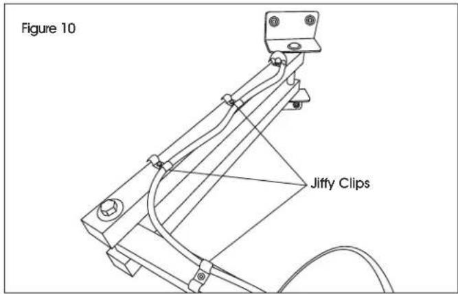
text_image
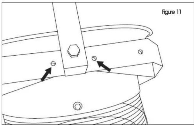
Figure 10 Jiffy ClipsSTOP BOLT (OPTIONAL)
- To prevent fan from rotating 360°, insert a 5/16" shoulder bolt through the hole on either side of the center hole of the yoke. Secure with 5/16" locknut using a 13 mm wrench. (See Figure 11)
natural_image
Technical line drawing of a mechanical component with arrows indicating features (no text or symbols)natural_image
Technical line drawing of two metal beams with mounting holes (no text or symbols)1 Ensamble de Soporte
text_image
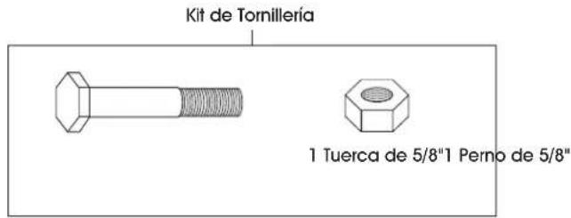
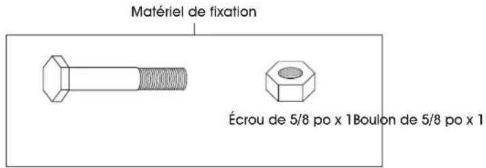
Kit de Tornillería 1 Tuerca de 5/8"1 Perno de 5/8"ENSAMBLE DEL SOPORTE DE PARED

natural_image
Simple line drawing of a bent pipe or support structure (no text or symbols)natural_image
Simple line drawing of an L-shaped metal bracket (no text or symbols)1 Base Vertical
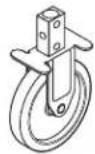
2 Ruedas
natural_image
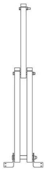
Pure technical line drawing of a vertical support structure without any text, numbers, or symbols1 Brazo de Andén
text_image
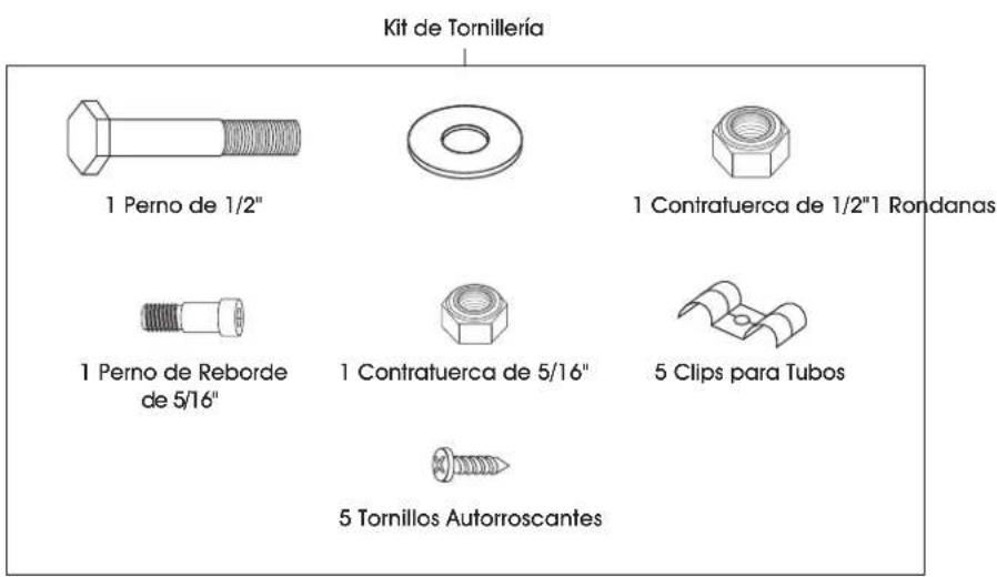
Kit de Tornillería 1 Perno de 1/2" 1 Contratuerca de 1/2"1 Rondanas 1 Perno de Reborde de 5/16" 1 Contratuerca de 5/16" 5 Clips para Tubos 5 Tornillos Autorroscantesnatural_image
Two simple metal frame structures with mounting holes, no text or symbols presentEnsemble de support x 1
natural_image
Technical line drawings of four different mechanical components: a bracket, a bent rod, a curved bracket, and a wheel (no text or symbols present)Support x 2 Support de plancher x 2 Support vertical x 1 Roulette x 2
natural_image
Technical line drawing of a mechanical device with two views (top and side), no text or symbols presentnatural_image
Technical line drawing of a mechanical device with rollers and a bracket, labeled as Figure 3 (no text or symbols on the diagram itself)MONTAGE DU SOCLE MOBILE SUITE
natural_image
Technical line drawing of a mechanical device with pulleys and screws, labeled as Figure 4 (no text or symbols on the diagram itself)natural_image
Technical line drawing of a mechanical assembly with a cylindrical component and two bolts, labeled 'Figure 7' (no text or symbols on the diagram itself)PIÈCES DE BRAS DE QUAI
natural_image
Pure technical line drawing of a vertical support structure without any text, numbers, or symbolsBras de quai x 1