
CMCW350 - Electric planer Craftsman - Free user manual and instructions
Find the device manual for free CMCW350 Craftsman in PDF.

| Product type | Cordless electric planer |
| Brand | Craftsman |
| Model | CMCW350 |
| Power source | Lithium-ion battery pack (20 V max) |
| Adjustable planing depth | 0 to 2 mm (0.079 in) |
| Adjustment steps | 0.1 mm per click |
| Edge/rabbet guide | Yes, up to 12 mm depth |
| Chamfer grooves | 3 mm, 5 mm, 7 mm |
| Dust port | With vacuum adapter and dust bag |
| Spring-loaded blade guard | Yes |
| Rest stand | Yes, automatic |
| No-load speed | Approximately 15,000 RPM |
| Blades | 2 carbide blades, reversible and replaceable |
| Belt | Replaceable |
| AirLock connection system | Yes (compatible with CRAFTSMAN extractors) |
| Intended use | Planing, chamfering, and rabbeting of wood and wood-based products |
| Maintenance | Regular cleaning of vents, lubrication not required |
| Repairs | Authorized Craftsman service center only |
| Warranty | 3-year limited |
| Included accessories | Edge/rabbet guide, dust bag, vacuum adapter, hex key |
Frequently Asked Questions - CMCW350 Craftsman
User questions about CMCW350 Craftsman
0 question about this device. Answer the ones you know or ask your own.
Ask a new question about this device
Download the instructions for your Electric planer in PDF format for free! Find your manual CMCW350 - Craftsman and take your electronic device back in hand. On this page are published all the documents necessary for the use of your device. CMCW350 by Craftsman.
USER MANUAL CMCW350 Craftsman
1 Blade guard
2 Battery pack
3 Battery release button
4 Lock-off button
5 Trigger switch
6 Planing depth adjustment knob/front handle
7 Main handle
8 Front shoe
9 Edge/rabbet guide
10 Planing depth graduation
11 Wrench
12 Belt cover
13 Dust extraction port
14 Dust bag
15 Chip discharge chute
16 Hex wrench
17 Vacuum adaptor
18 Edge/rabbet guide mount
WARNING: Read all safety warnings, instructions, illustrations, and specifications in this manual, including the battery and
charger sections provided in an original tool manual or the separate Batteries and Chargers manual.
Manuals can be obtained by contacting Customer Service. Failure to follow the warnings and instructions may result in electric shock, fire and/or serious injury.
Definitions: Safety Alert Symbols and Words
This instruction manual uses the following safety alert symbols and words to alert you to hazardous situations and your risk of personal injury or property damage.
RANGER: Indicates an imminently hazardous situation which, if not avoided, will result in death or serious injury.
WARNING: Indicates a potentially hazardous situation which, if not avoided, could result in death or serious injury.
CAUTION: Indicates a potentially hazardous situation which, if not avoided, may result in minor or moderate injury.
(Used without word) Indicates a safety related message.
NOTICE: Indicates a practice not related to personal injury which, if not avoided, may result in property damage.


English (original instructions) 5
| Français (traduction de la notice d'instructions originale) | 11 |
| Español (traducido de las instrucciones originales) | 17 |
Fig. B Fig. C
natural_image
Technical line drawing of a mechanical component with no visible text or symbols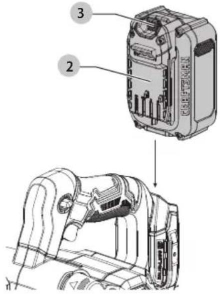
Fig. D
CORRECT/ CORRECT /CORRECTO
Fig. E
INCORRECT/ INCORRECT /INCORRECTO
natural_image
Technical line drawing of a mechanical assembly (no text or symbols)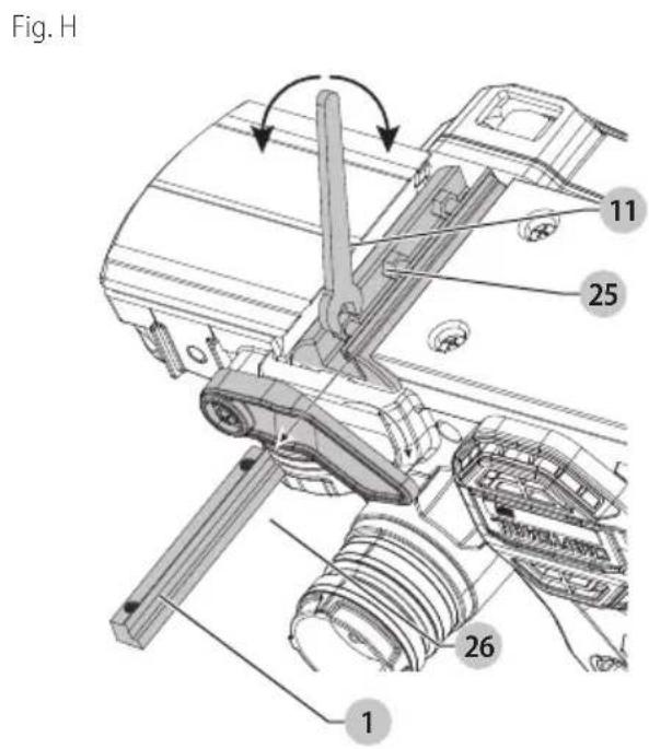
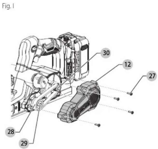
Fig. J
CARBIDE BLADE/ LAME AU CARBURE /HOJA DE CARBURO
natural_image
Technical diagram of a circular mechanical component with four slots and a central bore (no text or symbols)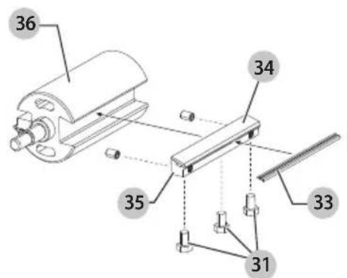
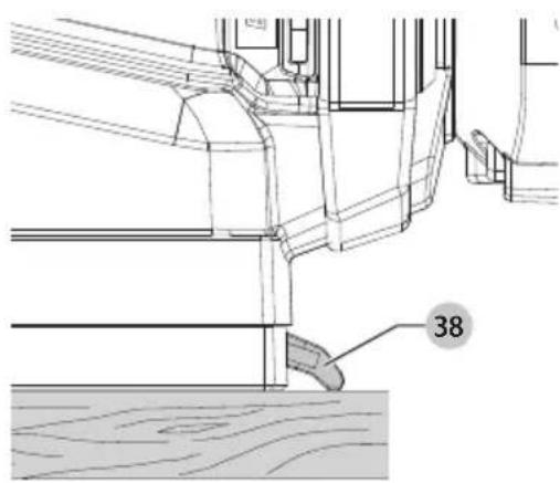
Fig. LFig. K
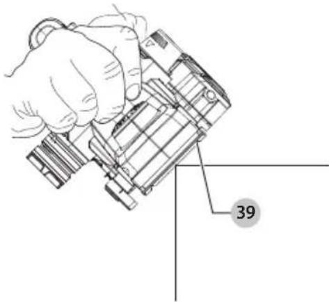
Fig. M1
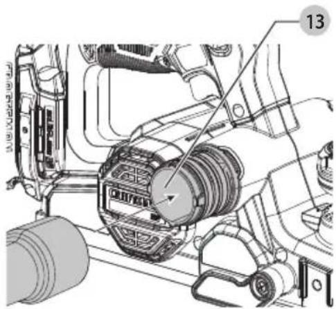
Fig. M2
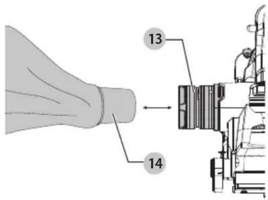
Fig. N1
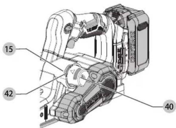
Fig. N2
natural_image
Technical line drawing of a mechanical assembly with labeled component 41 (no readable text or symbols)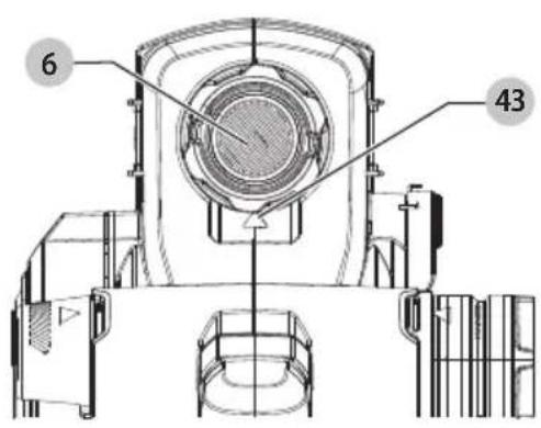
Fig. PFig. O
Intended Use
This planer is designed for DIY applications of wood and wood products.
DO NOT use under wet conditions or in presence of flammable liquids or gases.
This planer is a consumer power tool. DO NOT let children come into contact with the tool. Supervision is required when inexperienced operators use this tool.
GENERAL POWER TOOL SAFETY WARNINGS
WARNING: Read all safety warnings, instructions, illustrations and specifications provided with this power tool. Failure to follow all instructions listed below may result in electric shock, fire and/or serious injury.
SAVE ALL WARNINGS AND INSTRUCTIONS FOR FUTURE REFERENCE.
The term "power tool" in the warnings refers to your mains-operated (corded) power tool or battery-operated (cordless) power tool.
1) Work Area Safety
a) Keep work area clean and well lit. Cluttered or dark areas invite accidents.
b) Do not operate power tools in explosive atmospheres, such as in the presence of flammable liquids, gases or dust. Power tools create sparks which may ignite the dust or fumes.
c) Keep children and bystanders away while operating a power tool. Distractions can cause you to lose control.
2) Electrical Safety
a) Power tool plugs must match the outlet. Never modify the plug in any way. Do not use any adapter plugs with earthed (grounded) power tools. Unmodified plugs and matching outlets will reduce risk of electric shock.
b) Avoid body contact with earthed or grounded surfaces, such as pipes, radiators, ranges and refrigerators. There is an increased risk of electric shock if your body is earthed or grounded.
c) Do not expose power tools to rain or wet conditions. Water entering a power tool will increase the risk of electric shock.
d) Do not abuse the cord. Never use the cord for carrying, pulling or unplugging the power tool. Keep cord away from heat, oil, sharp edges or moving parts.
Damaged or entangled cords increase the risk of electric shock.
e) When operating a power tool outdoors, use an extension cord suitable for outdoor use. Use of a cord suitable for outdoor use reduces the risk of electric shock.
f) If operating a power tool in a damp location is unavoidable, use a ground fault circuit interrupter (GFCI) protected supply. Use of a GFCI reduces the risk of electric shock.
3) Personal Safety
a) Stay alert, watch what you are doing and use common sense when operating a power tool. Do not use a power tool while you are tired or under the influence of drugs, alcohol or medication. A moment of inattention while operating power tools may result in serious personal injury.
b) Use personal protective equipment. Always wear eye protection. Protective equipment such as a dust mask,
non-skid safety shoes, hard hat, or hearing protection used for appropriate conditions will reduce personal injuries.
c) Prevent unintentional starting. Ensure the switch is in the off position before connecting to power source and/or battery pack, picking up or carrying the tool. Carrying power tools with your finger on the switch or energizing power tools that have the switch on invites accidents.
d) Remove any adjusting key or wrench before turning the power tool on. A wrench or a key left attached to a rotating part of the power tool may result in personal injury.
e) Do not overreach. Keep proper footing and balance at all times. This enables better control of the power tool in unexpected situations.
f) Dress properly. Do not wear loose clothing or jewelry. Keep your hair and clothing away from moving parts. Loose clothes, jewelry or long hair can be caught in moving parts.
g) If devices are provided for the connection of dust extraction and collection facilities, ensure these are connected and properly used. Use of dust collection can reduce dust-related hazards.
h) Do not let familiarity gained from frequent use of tools allow you to become complacent and ignore tool safety principles. A careless action can cause severe injury within a fraction of a second.
4) Power Tool Use and Care
a) Do not force the power tool. Use the correct power tool for your application. The correct power tool will do the job better and safer at the rate for which it was designed.
b) Do not use the power tool if the switch does not turn it on and off. Any power tool that cannot be controlled with the switch is dangerous and must be repaired.
c) Disconnect the plug from the power source and/or remove the battery pack, if detachable, from the power tool before making any adjustments, changing accessories, or storing power tools. Such preventive safety measures reduce the risk of starting the power tool accidentally.
d) Store idle power tools out of the reach of children and do not allow persons unfamiliar with the power tool or these instructions to operate the power tool. Power tools are dangerous in the hands of untrained users.
e) Maintain power tools and accessories. Check for misalignment or binding of moving parts, breakage of parts and any other condition that may affect the power tool's operation. If damaged, have the power tool repaired before use. Many accidents are caused by poorly maintained power tools.
f) Keep cutting tools sharp and clean. Properly maintained cutting tools with sharp cutting edges are less likely to bind and are easier to control.
g) Use the power tool, accessories and tool bits, etc. in accordance with these instructions, taking into account the working conditions and the work to be performed.
Use of the power tool for operations different from those intended could result in a hazardous situation.
h) Keep handles and grasping surfaces dry, clean and free from oil and grease. Slippery handles and grasping surfaces do not allow for safe handling and control of the tool in unexpected situations.
ENgLIsH
5) Battery Tool Use and Care
a) Recharge only with the charger specified by the manufacturer. A charger that is suitable for one type of battery pack may create a risk of fire when used with another battery pack.
b) Use power tools only with specifically designated battery packs. Use of any other battery packs may create a risk of injury and fire.
c) When battery pack is not in use, keep it away from other metal objects, like paper clips, coins, keys, nails, screws or other small metal objects, that can make a connection from one terminal to another. Shorting the battery terminals together may cause burns or a fire.
d) Under abusive conditions, liquid may be ejected from the battery; avoid contact. If contact accidentally occurs, flush with water. If liquid contacts eyes, additionally seek medical help. Liquid ejected from the battery may cause irritation or burns.
e) Do not use a battery pack or tool that is damaged or modified. Damaged or modified batteries may exhibit unpredictable behavior resulting in fire, explosion or risk of injury.
f) Do not expose a battery pack or tool to fire or excessive temperature. Exposure to fire or temperature above 265 °F (130 °C) may cause explosion.
g) Follow all charging instructions and do not charge the battery pack or tool outside the temperature range specified in the instructions. Charging improperly or at temperatures outside the specified range may damage the battery and increase the risk of fire.
6) Service
a) Have your power tool serviced by a qualified repair person using only identical replacement parts. This will ensure that the safety of the power tool is maintained.
b) Never service damaged battery packs. Service of battery packs should only be performed by the manufacturer or authorized service providers.
Safety Instructions for Planers
- Wait for the cutter to stop before setting the tool down. An exposed rotating cutter may engage the surface leading to possible loss of control and serious injury.
- Hold the power tool by insulated gripping surfaces only, because the cutter may contact hidden wiring. Cutting a "live" wire may make exposed metal parts of the power tool "live" and could give the operator an electric shock.
- Use clamps or another practical way to secure and support the workpiece to a stable platform. Holding the work by your hand or against the body leaves it unstable and may lead to loss of control.
- Make certain that the switch is in the off position before installing the battery.
- Be sure to switch OFF immediately if tool is jammed in work.
- Be sure tool is set for correct depth before turning switch to ON.
- Be sure to maintain tool with care. Follow instructions for lubricating and changing accessories.
- Be sure that the blades are mounted as described in the instruction manual and check that all screws are firmly tightened before installing the battery.
-
Keep air vents unobstructed for proper motor cooling.
-
DO NOT lay tool down on shoe when the blades are exposed. This can chip the blades.
- Keep side discharge chute unobstructed at all times.
- Never reach under the tool for any reason unless it is turned off and BATTERY IS REMOVED. BLADES ARE EXPOSED AND EXTREMELY SHARP.
- Use this tool for working with wood and wood products only.
• Always make sure the work surface is free from nails and other foreign objects. - Always operate planer with two hands. Never operate without securely holding the front handle.
- Planer blades are extremely sharp. Handle with great care.
- Clean out your tool often, especially after heavy use.
Additional Safety Information
WARNING: Never modify the power tool or any part of it. Damage or personal injury could result.
WARNING: ALWAYS use safety glasses. Everyday eyeglasses are NOT safety glasses. Also use face or dust mask if cutting operation is dusty. ALWAYS WEAR CERTIFIED SAFETY EQUIPMENT:
• ANSI Z87.1 eye protection (CAN/CSA Z94.3),
• ANSI S12.6 (S3.19) hearing protection,
• NIOSH/OSHA/MSHA respiratory protection.
WARNING: Some dust created by power sanding, sawing, grinding, drilling, and other construction activities contains chemicals known to the State of California to cause cancer, birth defects or other reproductive harm. Some examples of these chemicals are:
- lead from lead-based paints,
• crystalline silica from bricks and cement and other masonry products, and
• arsenic and chromium from chemically-treated lumber.
Your risk from these exposures varies, depending on how often you do this type of work. To reduce your exposure to these chemicals: work in a well ventilated area, and work with approved safety equipment, such as those dust masks that are specially designed to filter out microscopic particles.
- Wear protective clothing and wash exposed areas with soap and water. Allowing dust to get into your mouth, eyes, or lay on the skin may promote absorption of harmful chemicals. Direct particles away from face and body.
- Use the appropriate dust extractor vacuum to remove the vast majority of static and airborne dust. Failure to remove static and airborne dust could contaminate the working environment or pose an increased health risk to the operator and those in close proximity.
- Use clamps or other practical ways to secure and support the workpiece to a stable platform. Holding the work by hand or against your body is unstable and may lead to loss of control and injury.
- Air vents often cover moving parts and should be avoided. Loose clothes, jewelry or long hair can be caught in moving parts.
AUTION: When not in use, place tool on its side on a stable surface where it will not cause a tripping or falling hazard. Some tools with large battery packs will stand upright on the battery pack but may be easily knocked over.
The label on your tool may include the following symbols. The symbols and their definitions are as follows:
V....volts
Hz.....hertz
min......minutes
or DC.....direct current
Class I Construction (grounded)
.../min.....per minute
BPM.....beats per minute
ClassII Construction (double insulated)
n_0 ...... no load speed
n......rated speed
PSI..... pounds per square inch
earthing terminal
⚠️ ____ safety alert symbol
▲......visible radiation—do not stare into the light
......wearrespiratory protection
...... wear eye protection
O....wearhearing protection
read all documentation
do not expose to rain
ASSEMBLY AND ADJUSTMENTS
WARNING: To reduce the risk of serious personal injury, turn unit off and remove the battery pack before making any adjustments or removing/installing attachments or accessories. An accidental start-up can cause injury.
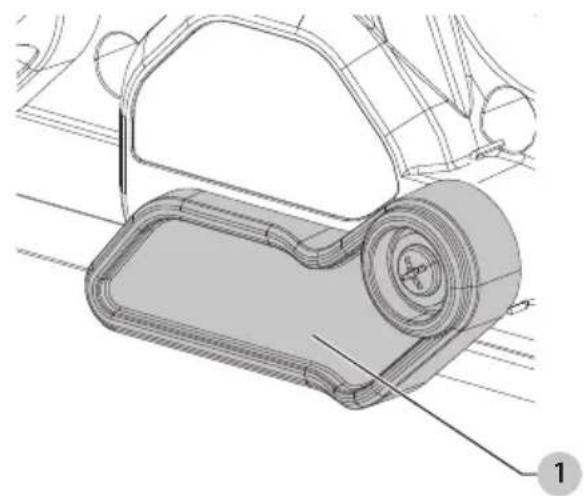
Blade Guard (Fig. B)
- Ensure that the spring-loaded blade guard 1 is in proper working order before using the planer.
WARNING: Cut hazard. Do not remove guard.
OPERATION
WARNING: To reduce the risk of serious personal injury, turn unit off and remove the battery pack before making any adjustments or removing/installing attachments or accessories. An accidental start-up can cause injury.
Installing and Removing the Battery Pack (Fig. C)
WARNING: Ensure the tool/appliance is in the off position before inserting the battery pack.
NOTE: For best results, make sure your battery pack is fully charged.
-
To install the battery pack 2 into the tool handle, align the battery pack with the rails inside the tool's handle and slide it into the handle until the battery pack is firmly seated in the tool and ensure that it does not disengage.
-
To remove the battery pack from the tool, press the battery pack release button 3 and firmly pull the battery pack out of the tool handle. Insert battery into the charger.
NOTE: For best results, use a 4.0 ah or higher battery pack.
Trigger Switch (Fig. A)
WARNING: This tool has no provision to lock the switch in the ON position and should never be locked ON by any other means. Release the trigger switch lock-off button 4 by pressing the button.
CAUTION: Allow the tool to reach full speed before touching tool to the work surface. Lift the tool from the work surface before turning the tool off.
To start the planer, depress the trigger switch 5.
To turn the planer off, release the trigger switch.
Adjusting the Planing Depth (Fig. A)
To adjust the depth of cut, turn the planing depth adjustment knob 6. Each click of the planing depth graduation 10 scale is equal to 0.1 mm of depth up to the maximum depth of cut of approximately 5/64" (2.0 mm). It is recommended that test cuts be made in scrap wood after each re-adjustment to make sure that the desired amount of wood is being removed by the planer. Several shallow passes (rather than one deep one) will produce a smoother finish.
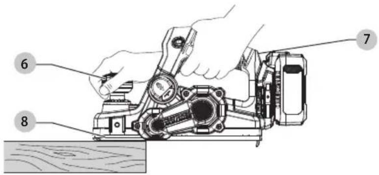
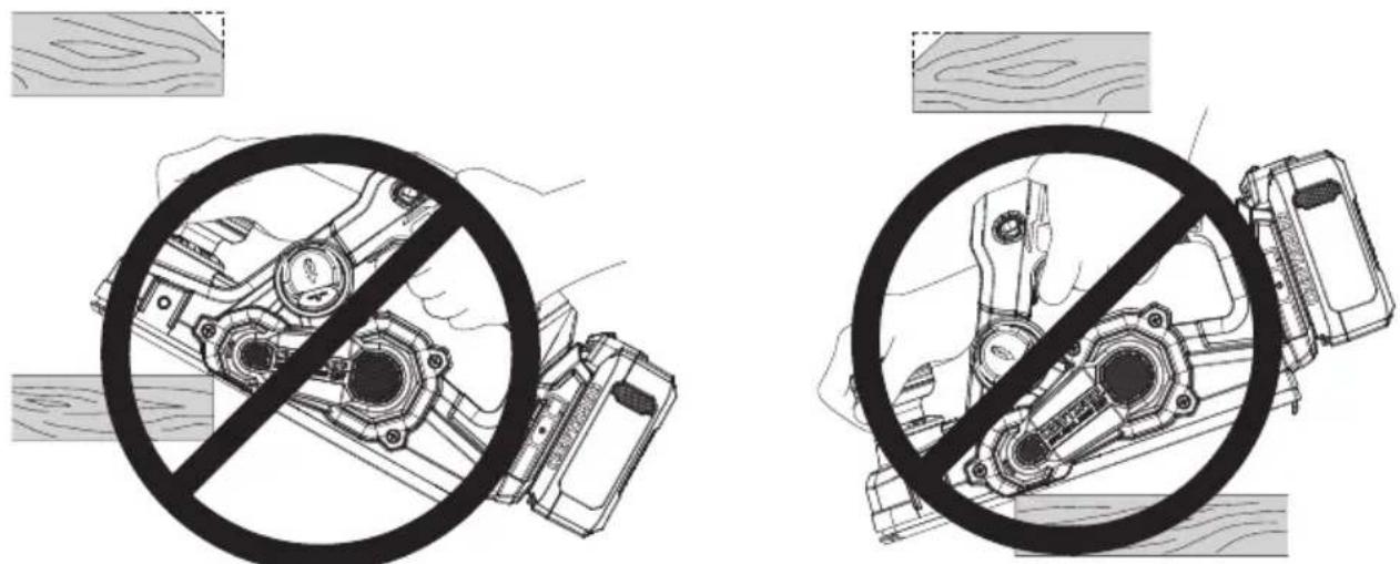
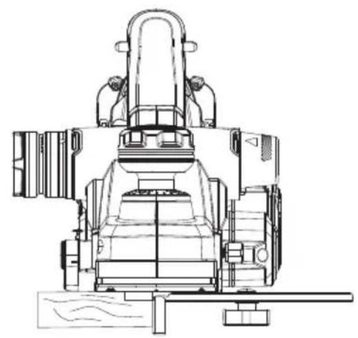
Planing (Fig. A, D, E)
CAUTION: Allow the tool to reach full speed before touching tool to the work surface. Lift the tool from the work surface before turning the tool off.
Hold the planer in the correct position with one hand on the front handle 6 and the other hand on the main handle 7. Place the front shoe 8 on the surface to be planed, making certain that the cutting blades are not touching the surface. Push down firmly on the front handle of the planer so that the front shoe is ABSOLUTELY FLAT on the work surface. Squeeze the trigger switch and allow the motor to reach full speed before touching the planer blades to the work surface.
Move the tool slowly into the work and maintain downward pressure to keep the planer flat. Be particularly careful to keep the tool flat at the beginning and the end of the work surface.
Planing Tip: For a smoother appearance, fasten a piece of scrap wood to the end of the piece you are planing. Don't stop planing until the cutting blades of the planer are past your workpiece and into the scrap material.
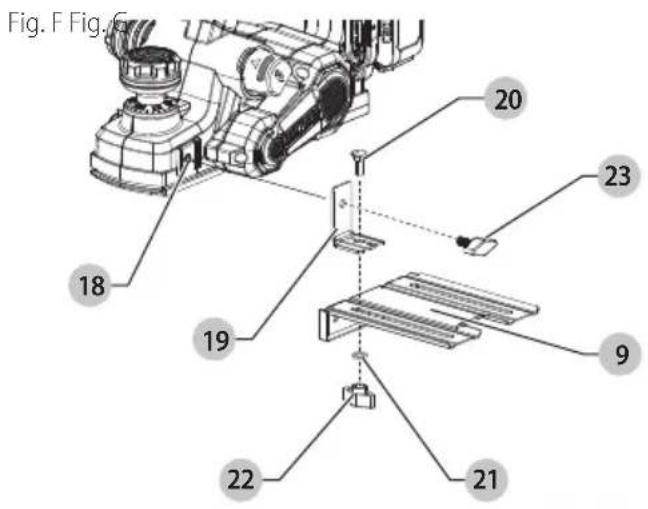
Edge/Rabbet Guide (Fig. A, F, G)
- The edge/rabbet guide 9 can be installed on either side of your planer. The planer can make rabbit cuts up to 0.5" (12 mm).
Assembling Edge/Rabbet Guide (Fig. F)
- Place the mounting bracket 19 on top of the edge/rabbet guide 9.
- Slide the mounting bracket bolt 20 through the mounting bracket, guide, and washer 21 and fasten all together with the wing nut 22.
- Once assembled, slide the mounting bolt 23 through the top of the mounting bracket and into the edge/rabbet guide mount 18.
- Fasten all bolts securely.
To Install Edge/Rabbet Guide
- Thread the edge/rabbet guide 9 into the edge/rabbet guide mount 18 on the side of the planer.
- Loosen the wing nut 22 and adjust guide to desired distance.
- Securely tighten edge/rabbet guide adjustment knob.
- The edge/rabbet guide should be below the planer when installed correctly.
ENgLIsH
To Make a Rabbet Cut
- Turn the wing nut 22 to adjust the desired width of cut.
- Make several cuts until the desired depth is reached.
NOTE: It will be necessary to make quite a few cuts for most rabbet applications.
To Make an Edge Cut
- Turn the edge/rabbet guide tightening knob to adjust the desired width of cut.
- Make several cuts until the desired depth is reached.
NOTE: It will be necessary to make quite a few cuts for most rabbet applications.
To Change Blades (Fig. A, H)
WARNING: To reduce the risk of serious personal injury, turn tool off and remove the battery pack before making any adjustments or removing/installing attachments or accessories. An accidental start-up can cause injury.
CAUTION: Planer blades are extremely sharp. Handle with great care.
AUTION: Be sure that the blades are mounted as described in the instruction manual.
CAUTION: Inspect blades, carriers, guide bars, screws and drum covers for straightness and defects. Do not use any components that are suspect in any way.
AUTION: Carefully tighten all screws when attaching blades to the tool. Always check to make sure they are tightened securely.
AUTION: Always replace blades in pairs and use blades of the same weight dimensions.
To Remove Blade from Planer
- Place planer upside down.
- Loosen the three hex screws 25 using the wrench 11 supplied by turning the screws counterclockwise.
- Rotate the blade guard 1 downward. Carefully remove the blade 26 by sliding it out of the holder. A piece of wood may be used for this purpose.
- Reverse the blade so that the unused side comes in position. If both sides are worn, the blade must be replaced.
To Reinstall Blade
- Slide the blade sideways into the holder until it is against the end stop. Blade groove must be toward back of unit.
- Securely tighten the three nuts using the wrench supplied by turning it clockwise. Rotate the blade drum 180° and repeat for other blade.
- Always replace both blades.
Drive Belt (Fig. I)
To Replace Belt
- Loosen the belt cover screws 27 and remove the belt cover 12.
- Remove old belt 28.
- Place new belt over front pulley 29 then rotate belt clockwise while pushing belt onto back pulley 30.
- Attach belt cover and securely tighten screws.
NOTE: Before installing or replacing blades, clean out all chips or any foreign matter adhering to the planer blade or drum.
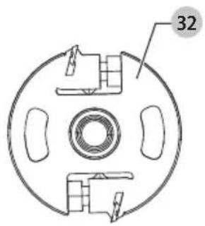
Reversible Carbide Blades (Fig. A, J)
To Remove Blade from Planer
a. Loosen and remove the three hex head screws 31 with the wrench 11 provided. Remove the blade guide bar assembly from the drum block 32.
b. Remove the blade carrier/guide bar assembly. Carefully remove the carbide blade 33.
To Replace the Blade
a. Remove the adjusted blade carrier/guide bar assembly from the gauge plate 34 and place the heel of the guide bar 35 into the groove on the drum.
b. Place the drum cover 36 over the blade carrier/guide bar assembly. Loosely screw the three hex head screws into the drum so that there is a small gap between the drum and the blade carrier 37.
c. Slide the carbide blade between the drum and the blade carrier from the side so that the rib on the blade carrier sets into the groove in the blade.
d. Center the carbide blade under the blade carrier making sure the blade is clear of the tool housing on both sides.
e. Securely tighten the three hex head screws to the drum with the wrench.
1. Repeat procedure for the other blade.
NOTE: Before installing or replacing blades, clean out all chips or any foreign matter adhering to the planer blade or drum.
Kickstand (Fig. K)
- Your planer is equipped with a kickstand 38 that automatically lowers into place when the tool is lifted from the work surface. When planing, the kickstand raises as the tool is pushed forward. When the kickstand is lowered, the planer can set on the work surface without the blade touching.
CAUTION: Do not lock the trigger switch on and engage the kickstand. The vibration of the running motor will cause the planer to move, possibly falling from the workpiece.
CAUTION: Be sure that the kickstand is correctly extended when setting the planer on a work surface.
Edge Chamfering (Fig. L)
- Your planer has three precision chamfering grooves 3 mm, 5 mm and 7 mm 39. They are located in the front shoe and are used for planing along a corner of the material.
a. Adjust to desired depth of cut.
b. Place groove over edge of material.
c. Apply weight to front of shoe so groove is flat on material edge.
d. Hold tool with both hands keeping pressure on front handle.
NOTE: It's a good idea to try a piece of scrap wood before doing finish work.
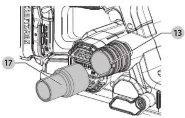
Dust Extraction (Fig. A, M1, M2)
Your planer has a built-in dust extraction port 13 which allows either a dust bag 14 or vacuum adaptor 17 to be connected. The built-in outlet utilizes the CRAFTSMAN AirLock connection system making it compatible with the CRAFTSMAN dust extractor.
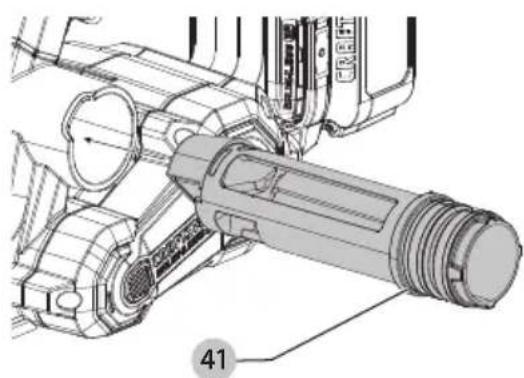
Change of Dust Extraction Direction (Fig. A, N1, N2)
- Dust extraction direction can be changed to the right or left. To change the direction, press the cap of the chip extraction tubing 40 then pull it out.
- Fit it in the opening on the opposite side of chip discharge chute 15 so that the protrusion 41 fits to the housing recess 42.
- Dust extraction tubing can be pulled out and inserted either way, then the chip will come out from either direction.
Adjusting Planing Depth (Fig. 0)
- Planing depth is infinitely variable from 0 to 5/64" (2 mm). To adjust the cutting depth, rotate the depth adjustment knob/front handle 6 clockwise from the "0" position. The cutting depth will increase from 0 to as much as 0.079" (2 mm). Use the adjustment arrow 43 to determine the depth setting.
- It is recommended that test cuts be made in scrap wood after each re-adjustment to make sure that the desired amount of wood is being removed by the planer. Several shallow passes (rather than one deep one) will produce a smoother finish.
Vacuum Adaptor (Fig. P)
- Slide the vacuum adaptor 17 over the dust extraction port 13.
- Connect a vacuum cleaner hose (not included) to the adaptor.
- To prevent chips from coming out of the opposite side of the chip discharge chute, remove and reinstall the dust extraction tubing in the opposite direction of the adapter.
To Attach the Dust Bag (Fig. M2)
(Optional accessory provided on some models)
While holding the planer, slide the dust bag 14 collar onto the dust extraction port 13.
To Empty The Dust Bag
- While holding the planer, remove the dust bag 14 by sliding it off the dust extraction port 13.
- Gently shake or tap the dust bag to empty.
- Reattach the dust bag back onto the dust extraction port. You may notice that all the dust will not come free from the bag. This will not affect planing performance but will reduce the planer's dust collection efficiency. To restore your planer's dust collection efficiency when you are emptying it, tap it on the side of the trash can or dust receptacle.
AUTION: Never operate these tools unless the dust collector is in place. Planing dust exhaust may create a breathing hazard.
MAINTENANCE
WARNING: To reduce the risk of serious personal injury, turn unit off and remove the battery pack before making any adjustments or removing/installing attachments or accessories. An accidental start-up can cause injury.
Your CRAFTSMAN power tool has been designed to operate over a long period of time with minimum maintenance. Continuous satisfactory operation depends upon proper tool care and regular cleaning.
Cleaning
WARNING: Blow dirt and dust out of all air vents with clean, dry air at least once a week. To minimize the risk of eye injury, always wear ANSI Z87.1 approved eye protection when performing this procedure.
WARNING: Never use solvents or other harsh chemicals for cleaning the non-metallic parts of the tool. These chemicals may weaken the plastic materials used in these parts. Use a cloth dampened only with water and mild soap. Never let any liquid get inside the tool; never immerse any part of the tool into a liquid.
Chip Discharge Chute Cleaning Instructions (Fig. A)
If the unit is clogged with dust or chips, use a non-metallic stick to push the obstruction out of the chip discharge chute 15. Never stick your finger into the chute.
Accessories
WARNING: Since accessories, other than those offered by CRAFTSMAN, have not been tested with this product, use of such accessories with this product could be hazardous. To reduce the risk of injury, only CRAFTSMAN-recommended accessories should be used with this product. Recommended accessories for use with your product are available at extra cost from your local dealer or authorized service center. If you need assistance in locating any accessory, please contact CRAFTSMAN. Call 1-888-331-4569.
Repairs
The charger and batteries are not serviceable. There are no serviceable parts inside the charger or battery pack.
WARNING: To assure product SAFETY and RELIABILITY, repairs, maintenance and adjustment (including brush inspection and replacement, when applicable) should be performed by a factory service center or an authorized service center. Always use identical replacement parts.
Register Online
Thank you for your purchase. Register your product now for:
- WARRANTY SERVICE: Registering your product will help you obtain more efficient warranty service in case there is a problem with your product.
- CONFIRMATION OF OWNERSHIP: In case of an insurance loss, such as fire, flood or theft, your registration of ownership will serve as your proof of purchase.
- FOR YOUR SAFETY: Registering your product will allow us to contact you in the unlikely event a safety notification is required under the Federal Consumer Safety Act.
Register online at www.craftsman.com/account/login.
Three-Year Limited Warranty
For warranty terms, go to
www.craftsman.com/pages/warranty.
To request a written copy of the warranty terms, contact: Customer Service at CRAFTSMAN, 701 East Joppa Road, Towson, MD 21286 or call 1-888-331-4569.
LATIN AMERICA: This warranty does not apply to products sold in Latin America. For products sold in Latin America, see country-specific warranty information contained in the packaging, call the local company, or see website for warranty information.
ENgLIsH
FREE WARNING LABEL REPLACEMENT: If your warning labels become illegible or are missing, call 1-888-331-4569 for a free replacement.
Utilisation prévue
Eje Central Lázaro Cárdenas No. 18 - Local (55) 5588 9377 D, Col. Obrera
MERIDA, YUC
Calle 63 #459-A - Col. Centro (999) 928 5038
MONTERREY, N.L.
Av. Francisco I. Madero 831 Poniente - Col. (818) 375 23 13 Centro
PUEBLA, PUE
17 Norte #205 - Col. Centro (222) 246 3714
QUERETARO, QRO
Av. San Roque 274 - Col. San Gregorio (442) 2 17 63 14
SAN LUIS POTOSI, SLP
Col. Santa Fe Alvaro Obregon,
Ciudad de Mexico, Mexico.
C.P 01210
TEL(52) 55 53267100
R.F.C.BDE8106261W7
Registro en Línea
Blocs-piles CMCB201, CMCB202, CMCB204, CMCB2015, CMCB205, CMCB206, CMCB209, CMCB2011
Baterías
Chargers
Chargeurs CMCB100, CMCB101, CMCB102, CMCB104, CMCB1104, CMCB124
Cargadores
* Maximum initial battery voltage (measured without a workload) is 20 volts. Nominal voltage is 18.
* La tension initiale maximum du bloc-piles (mesurée à vide) est de 20 volts. La tension nominale est de 18.
* El máximo voltaje inicial de la batería (medido sin carga de trabajo) es 20 voltios. El voltaje nominal es de 18.
WARNING: Use of any other battery packs may create a risk of injury and fire.
NOTE: DO NOT charge when the battery pack is below 40^ F ( 4.5^ C) or above 104^ F ( 40^ C). Do not store or use the tool and battery pack in locations where the temperature may reach or exceed 104^ F ( 40^ C).
- Definitions: Safety Alert Symbols and Words
- Intended Use
- GENERAL POWER TOOL SAFETY WARNINGS
- SAVE ALL WARNINGS AND INSTRUCTIONS FOR FUTURE REFERENCE.
- 1) Work Area Safety
- 2) Electrical Safety
- 3) Personal Safety
- 4) Power Tool Use and Care
- ENgLIsH
- 5) Battery Tool Use and Care
- 6) Service
- Safety Instructions for Planers
- Additional Safety Information
- ASSEMBLY AND ADJUSTMENTS
- Blade Guard (Fig. B)
- OPERATION
- Installing and Removing the Battery Pack (Fig. C)
- Trigger Switch (Fig. A)
- Adjusting the Planing Depth (Fig. A)
- Planing (Fig. A, D, E)
- Edge/Rabbet Guide (Fig. A, F, G)
- Assembling Edge/Rabbet Guide (Fig. F)
- To Install Edge/Rabbet Guide
- To Make a Rabbet Cut
- To Make an Edge Cut
- To Change Blades (Fig. A, H)
- To Remove Blade from Planer
- To Reinstall Blade
- Drive Belt (Fig. I)
- To Replace Belt
- Reversible Carbide Blades (Fig. A, J)
- To Replace the Blade
- Repeat procedure for the other blade.
- Kickstand (Fig. K)
- Edge Chamfering (Fig. L)
- Dust Extraction (Fig. A, M1, M2)
- Change of Dust Extraction Direction (Fig. A, N1, N2)
- Adjusting Planing Depth (Fig. 0)
- Vacuum Adaptor (Fig. P)
- To Attach the Dust Bag (Fig. M2)
- (Optional accessory provided on some models)
- To Empty The Dust Bag
- MAINTENANCE
- Cleaning
- Chip Discharge Chute Cleaning Instructions (Fig. A)
- Accessories
- Repairs
- Register Online
- Three-Year Limited Warranty
- www.craftsman.com/pages/warranty.
- Utilisation prévue
- MERIDA, YUC
- MONTERREY, N.L.
- PUEBLA, PUE
- QUERETARO, QRO
- SAN LUIS POTOSI, SLP
- Registro en Línea
Brand : Craftsman
Model : CMCW350
Category : Electric planer