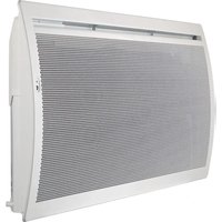
FPE 200E - Heating DIMPLEX - Free user manual and instructions
Find the device manual for free FPE 200E DIMPLEX in PDF.


| Product type | Infrared heater |
| Brand | Dimplex |
| Model | FPE 200E |
| Rated thermal output | 2.0 kW |
| Rated voltage | 1/N, 230 V~ |
| IP protection rating | IP24 (protected against water splashes) |
| Dimensions (W x H x D) | 1057 x 440 x 113 mm |
| Weight | 8.7 kg |
| Control type | Electronic room temperature regulator |
| Operating modes | Automatic (with weekly schedule and presence detection), Manual (comfort, Eco, anti-freeze) |
| Special functions | Window monitoring, presence detection, weekly schedule (P1 to P6), simple/code key lock, temperature memory |
| Safety | Overload limiter, child protection (<3 years keep away, 3-8 years under supervision), do not cover, automatic shut-off when window open |
| Cleaning and maintenance | Unplug and let cool. Clean with a soft damp cloth. Vacuum for dust deposits. Do not use scouring powder or wax. |
| Warranty | 2 years |
| Disposal | Do not dispose of with household waste. Take to a local recycling center. |
Frequently Asked Questions - FPE 200E DIMPLEX
User questions about FPE 200E DIMPLEX
0 question about this device. Answer the ones you know or ask your own.
Ask a new question about this device
Download the instructions for your Heating in PDF format for free! Find your manual FPE 200E - DIMPLEX and take your electronic device back in hand. On this page are published all the documents necessary for the use of your device. FPE 200E by DIMPLEX.
USER MANUAL FPE 200E DIMPLEX
natural_image
Exterior view of a white air conditioner unit with mesh grille pattern (no text or symbols visible)DCDimplex
| Montage- und Gebrauchsanweisung | Deutscheng |
| Installation and Operating Instructions | iano |
| Instructions de montage et d’utilisation | Françaisita |
| Istruzioni d’uso e di montaggio |
Infrarot-Heizgerät
Infrared panel heater
| Modelle | A(mm) | B(mm) | C(mm) | D(mm) | E(mm) |
| FPE 050E 14 | 5 242 1 | 17 270 10 | 4 | ||
| FPE 100E 22 | 9 177 23 | 0 | |||
| FPE 150E 26 | 3 319 26 | 4 | |||
| FPE 200E 26 | 1 534 26 | 2 |
natural_image
Cross-sectional diagram of a mechanical joint or pipe system with a downward arrow indicating direction (no text or symbols present)natural_image
Diagram showing three sequential steps of a mechanical or optical assembly: pin alignment, folding, and resulting cross-section (no text or symbols)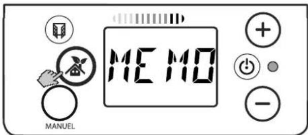
Symbol Mond (C): Eco-Temperatur
Programm P1
Wochenprogramm Ein
Sperren
Sperren
i HINWEIS
1. Notes for the user
i NOTE
Dear customer,
Keep these instructions in a safe place and pass them on to possible future owners.

CAUTION!
This device can be used by children aged 8 and over and by persons with limited physical, sensory or mental aptitude or lack of experience and/or knowledge, providing they are supervised or have been instructed in the safe use of the device and understand the associated potential dangers. Children must not play with the device. Cleaning and user maintenance may not be carried out by children without supervision!

CAUTION!
Children younger than 3 years of age must be kept away unless they are supervised constantly. Children between the ages of 3 and 8 may switch the device on and off if they are supervised or have been instructed in the safe use of the device and have understood the resulting dangers, providing that the device is positioned or installed in its normal place of use!

CAUTION!
Children between the ages of 3 and 8 may not switch on the device, clean the device or carry out maintenance!

CAUTION!
The device carries the symbol shown on the right, which indicates that the heating device must under no circumstances be covered with any objects.


CAUTION!
Some parts of the device can get very hot and cause burns. Particular caution must be taken with children or vulnerable people!

CAUTION!
Do not operate the heating device in rooms where highly inflammable substances are used (e.g. solvents).

CAUTION!
If the power cable is damaged, it must be replaced by the manufacturer or after-sales service representative or a person with comparable qualifications for switching off danger sources!

NOTE
Use device for room heating within enclosed rooms only.
2. Assembly, installation, minimum clearance

CAUTION!
Install the device in such a manner that it cannot be touched by a person in the bathtub or under the shower.

CAUTION!
Do not install the device directly below a wall socket.
The minimum clearances must be observed. In addition, a clearance of 1 meter is to be maintained in front of the unit.
The heating device must be aligned horizontally and installed on a vertical wall (see illustration).
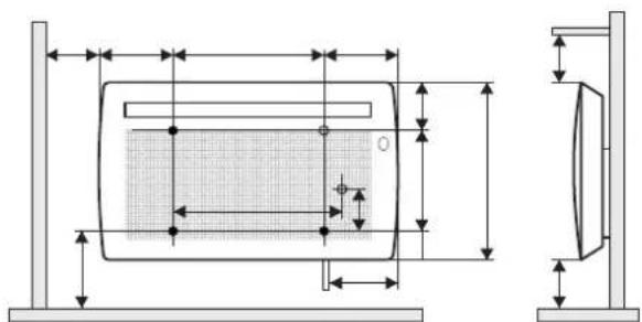
All dimensions in mm.
| Model | A(mm) | B(mm) | C(mm) | D(mm) | E(mm) |
| FPE 050E 145 242 1 | 17 270 104 | ||||
| FPE 100E 229 177 230 | |||||
| FPE 150E 263 319 264 | |||||
| FPE 200E 261 534 262 | |||||
During assembly, the safety area must be complied with according to the current installation regulations.
The supply connection socket must be accessible after installation.
Make sure that the inflow and outflow of air at the top and bottom of the device are unimpeded.
i NOTE
Installation on wooden walls is permissible.
Wall mounting

CAUTION!
The original wall bracket supplied on the rear of the device must be used!
i NOTE
Look out for electric cables or pipework in the wall when drilling.
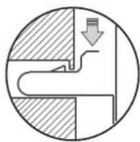
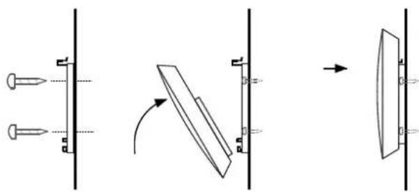
■ Remove the wall bracket from the rear side of the device. To do this, press both springs down.
natural_image
Cross-sectional diagram of a mechanical or fluidic component with a downward arrow indicating flow or direction (no text or symbols)- Drill the fastening holes.
■ Screw the wall bracket securely to the wall.
■ Hook the device in the bottom slots of the wall bracket.
■ Fold the device up and engage in the springs to lock.
natural_image
Pure mechanical diagram showing pin alignment and rotation process without any text or symbols3. Electrical connection
The voltage specified on the type plate must match the line voltage.
The cable must not be in contact with the casing.
It is recommended that a separate electric circuit be provided for the power supply.
The device must only be installed and repaired by a qualified electrician in accordance with the applicable safety regulations. Heating device must be earthed! Connection may only take place on securely routed cables!
A disconnecting device with a contact opening of at least 3 mm at each pole (e.g. circuit breaker) must be provided in the permanently installed wiring.
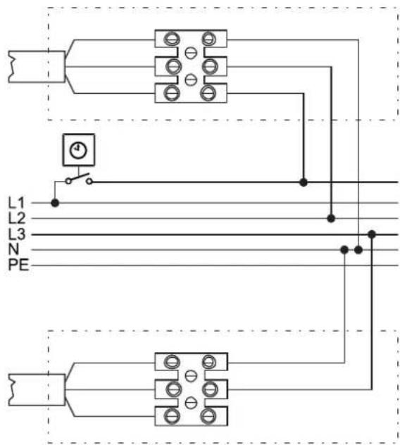
The electrical connection is shown below.
Connection options
If a central temperature reduction is to take place via the pilot wire, device connection A should be used, if not, device connection B.
i NOTE
The temperature reduction via the pilot wire has no function if the weekly program (P1 - P6) set on the controller is executed.
4. Overload protector
For your safety, the heating device is equipped with an overload protector. If the air circulation is interrupted (e.g. due to the air grille being covered or closed), the device switches off automatically.
In this case, the power supply to the heating device should be disconnected for a few minutes (switch off the fuse) to allow the device to cool down sufficiently. Before recommissioning the device, remove the reasons for the overload protector being triggered.
5. Cleaning
The device must be disconnected from the mains and allowed to cool down before cleaning and maintenance. Clean the outside of the device using a soft, damp cloth. Do not use scouring powder or furniture polish as this may damage the surface. Dust which gathers inside the device can be removed from the outside using a vacuum cleaner.
6. Control description
6.1 Control unit
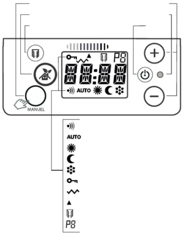
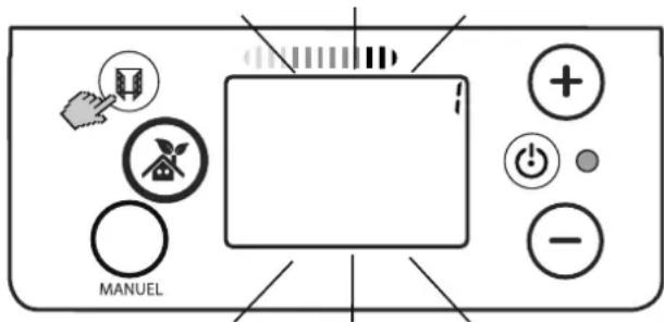
The heating device is equipped with an adjustable electronic controller with display, six keys and an LED. The control unit is located on the top on the right. All settings can be selected using the six keys on the user interface.
6.2 Key functions
On/off
Switching the heating device on or off.
Automatic operation
Room temperature control with:
■ Weekly program,
■ Presence detection.
Manual operation
Room temperature control by specifying:
■ Comfort temperature,
■ Eco temperature (lower temperature),
■ Frost protection temperature.
Window monitoring
Interruption of heating operation when window is open.
Setting keys + and -
Navigation through the menu and changing the setting values.
6.3 Display
Shows the current settings. The display lights up for approx. 10 seconds (factory setting) when this key is activated.
Heating operation on display
During heating operation, the HEATING OPERATION ON symbol appears. When the specified temperature is reached, the symbol disappears.
Energy efficiency display
The ENERGY EFFICIENCY display informs the user of the energy consumption depending on the set room temperature.
- Arrow on green: low energy consumption
- Arrow on red: high energy consumption
7. Possible operating modes
Window monitoring
The room heating device is equipped with a monitoring function that detects whether unnecessary energy is being consumed due to an open window. In this case, heating operation is interrupted. This function is set as active at the factory.
Presence detection
In automatic operation, the controller detects whether a person is in the room. The set comfort temperature remains active for as long as a person is detected. If the room is not in use, the temperature is lowered gradually to save energy:
By 1°C after 30 minutes, by 2°C after one hour. After more than 2 hours, the temperature is permanently lowered to the set eco temperature.
7.1 Automatic operation
The desired room temperature (comfort temperature) can be set with the + / - keys.
The presence detection is active. Weekly program with comfort and lower times can be activated.
7.2 Manual operation
The desired room temperature (comfort temperature) can be set with the + / - keys.
No presence detection.
Manual specification of the lower temperature (factory setting lower by 3.5°C).
Manual specification of the frost protection temperature (7°C).
7.3 Weekly program
Each weekday can be assigned a total of six heating programs (P1 to P6).
Heating programs P1 to P3 are fixed.
Heating programs P4 to P6 can be set individually.
Each of the heating programs P4 - P6 can be assigned up to three comfort and three lower times (eco temperature). Only whole hours can be set. The executed heating program is shown on the display.
i NOTE
For a particularly energy-efficient operation, it is advisable to run a weekly program.
8. Operation
8.1 Switching the heating device on/off
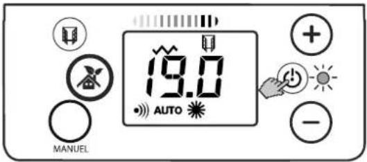
Press the ON/OFF key. A melody sounds.
- Display illuminates green: Heating device switched on.
- Display illuminates red: Heating device switched off.
8.2 Manual operation
Press the MANUAL key once or multiple times.
The operating mode switches between:
- Comfort temperature,
- Eco temperature (lowered temperature)
- Frost protection (display HD).
Setting the comfort temperature
i NOTE
Temperature setting only possible if comfort temperature is pre-selected.
■ Press the MANUAL key once or multiple times until the COMFORT TEMPERATURE symbol appears.
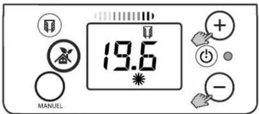
■ Press the + / - keys to set the desired temperature value.
Lowering the temperature
NOTE
Recommended for periods of absence lasting less than 24 hours to save energy.
■ Press the MANUAL key once or multiple times until ECO appears.
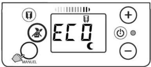
The temperature value is lowered by 3.5^ C compared with the set comfort temperature.
Specify the frost protection temperature
i NOTE
Recommended for periods of absence lasting longer than 24 hours to save energy.
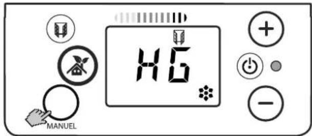
Specify a frost protection temperature of 7^ C.
■ Press the MANUAL key once or multiple times until HD appears.
8.3 Automatic operation
■ Press the AUTOMATIC OPERATION key.
■ Press the + / - keys to set the desired temperature value.
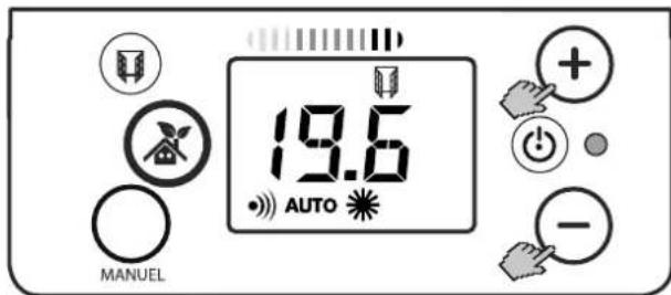
The presence detection is active. The controller detects whether a person is in the room. The set comfort temperature remains active for as long as a person is detected. If the room is not in use, the temperature is lowered gradually.
8.4 Saving the temperature value permanently
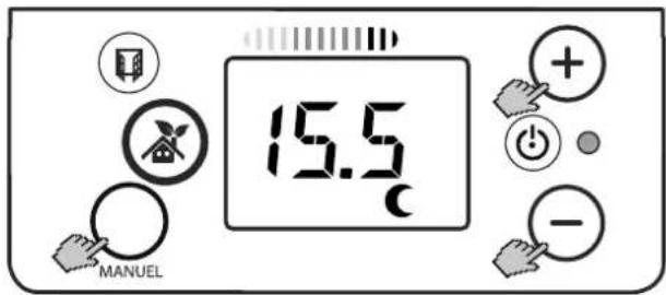
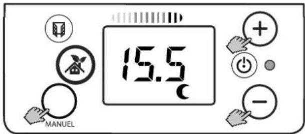
Save the temperature value for comfort temperature.
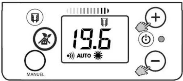
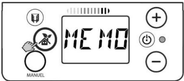
- Press the + / - keys to set the desired temperature value.
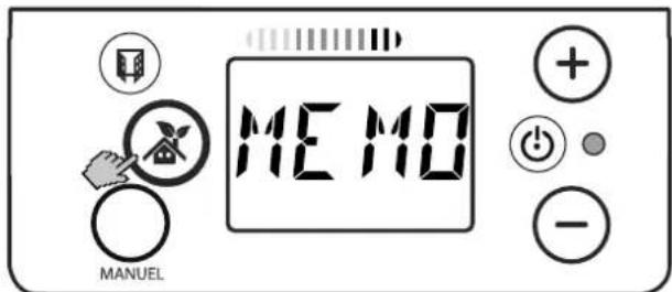
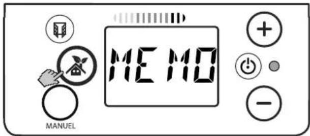
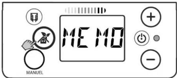
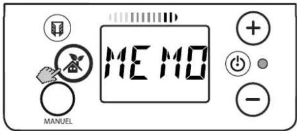
■ Press and hold the AUTOMATIC OPERATION key for 3 seconds. MEMO is shown.
The desired comfort temperature is saved.
9. Weekly program
Time-dependent specification of comfort and eco temperature. Fixed specified programs (P1 - P3) or freely set programs (P4 - P6) can be assigned to the relevant weekday.
9.1 Setting the time and weekday
The controller includes a realtime clock with weekly program.
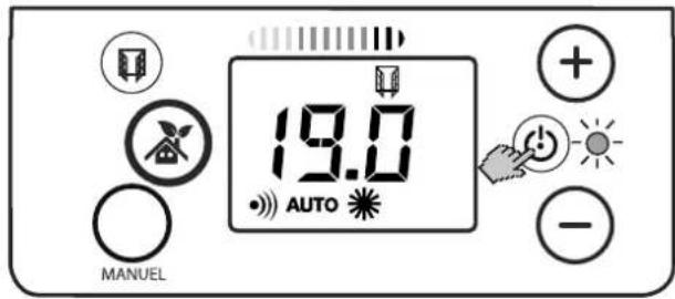
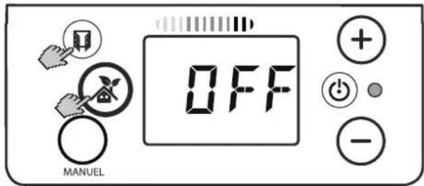
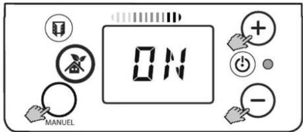
The time and weekday are set with the following steps:
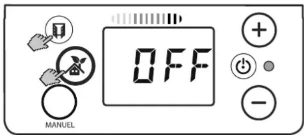
■ Press the ON key.
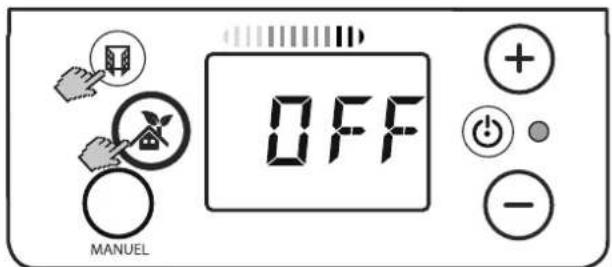
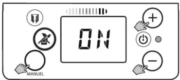
■ Press the WINDOW and AUTOMATIC OPERATION keys simultaneously for three seconds.
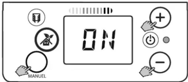
■ Press the + / - keys to switch to ON.
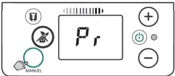
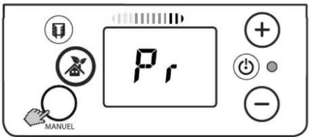
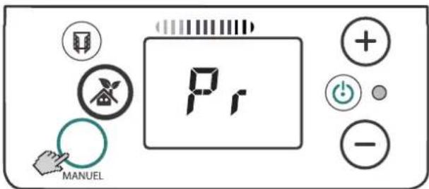
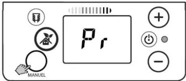
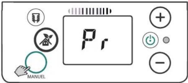
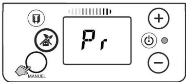
■ Confirm with the MANUAL key. Pr is shown.
■ Set to Hr with the + / - keys:
■ Press the MANUAL key. The hours display flashes.
■ Use the + / - keys to set the hours.
■ Press the MANUAL key. The minute display flashes.
■ Use the + / - keys to set the minutes.
■ Press the MANUAL key. The weekday display flashes.
Use the + / - keys to set the weekday.
(JO:LU = Monday, JO:MA = Tuesday,
JO:ME = Wednesday, JO:JE = Thursday,
JO:VE = Friday, JO:SA = Saturday,
JO:DI = Sunday).
■ Press the MANUAL key. Pr is shown.
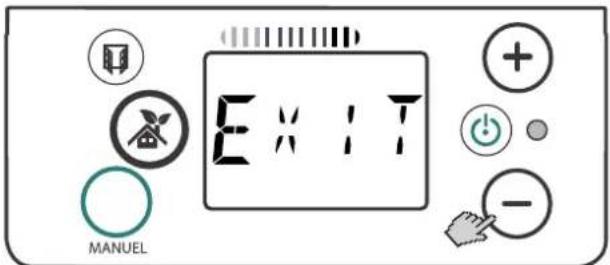
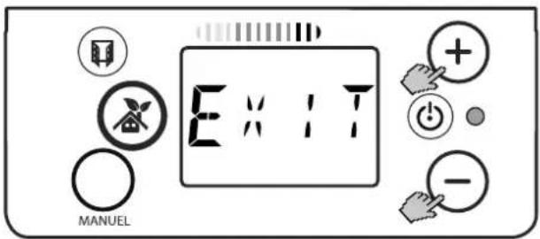
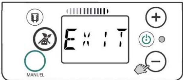
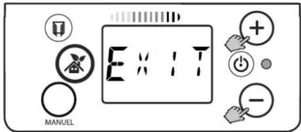
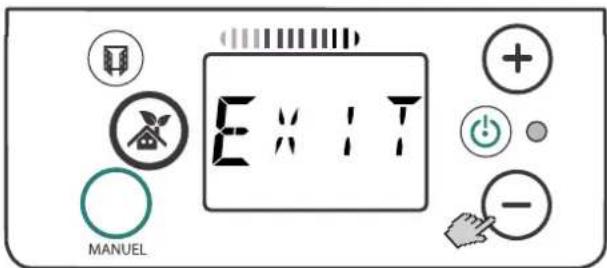
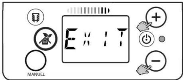
- Press the – key to switch to EXIT.
Press the MANUAL key. Main display appears.
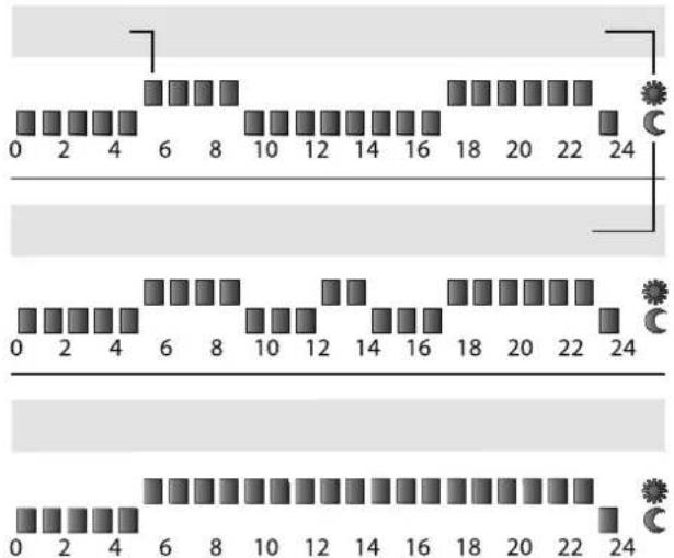
9.2 Fixed set heating programs P1 - P3
i NOTE
The time blocks for the programs P1 - P3 are fixed and can not be changed.
One time block (A): A whole hour.
Sun symbol (B): Comfort temperature
Moon symbol (C): Eco temperature
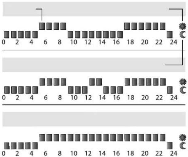
Program P1
Specification of a comfort temperature from 5 am to 9 am and from 5 pm to 11 pm.
Program P2
Specification of a comfort temperature from 5 am to 9 am, from 12 midday to 2 pm and from 5 pm to 11 pm.
Program P3
Specification of a comfort temperature from 5 am to 11 pm.
i NOTE
Specific days can be assigned to the programs P1 - P3. See section 5.3.
9.3 Freely adjustable heating programs P4 - P6
i NOTE
The programs P4 - P6 can be set individually and can be changed at any time.
Up to three comfort and three lower times can be defined for each program.
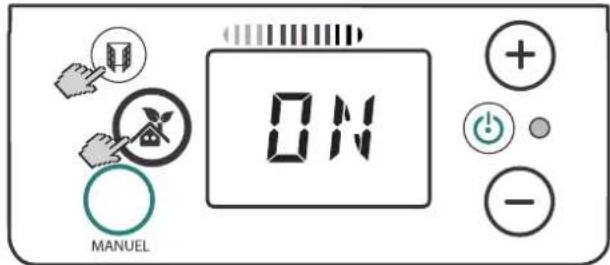
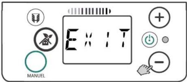
■ Press the WINDOW and AUTOMATIC OPERATION keys simultaneously for three seconds.
ON or OFF is shown.
- Use the + / - keys to switch to ON if necessary.
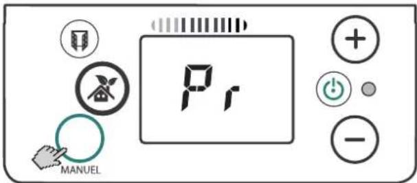
■ Confirm with the MANUAL key. Pr is shown.
- Press the + / - keys multiple times until program P4 is shown.
■ Press the MANUAL key. DE1 is shown.
■ Press the MANUAL key. Hour (H) appears.
■ Use the + / - keys to set the time for the comfort temperature.
■ Press the MANUAL key. A is shown.
■ Use the + / - keys to set the time for the lower temperature.
■ Press the MANUAL key. DE2 is shown.
■ Set the other comfort and lower times in the same way. Once all comfort and lower times are set, Pr is shown.
- Press the – key to switch to EXIT.
■ Press the MANUAL key to return to the main display.
9.4 Assigning the heating program to the weekday
The weekdays are shown on the display as follows:
- LU = Monday,
- MA = Tuesday,
- ME = Wednesday,
- JE = Thursday,
- VE = Friday,
- SA = Saturday,
- DI = Sunday
i NOTE
Factory setting:
Program P1 is assigned Monday to Friday.
Program P3 is assigned Saturday and Sunday.
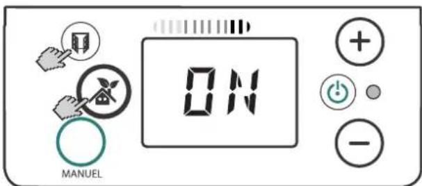
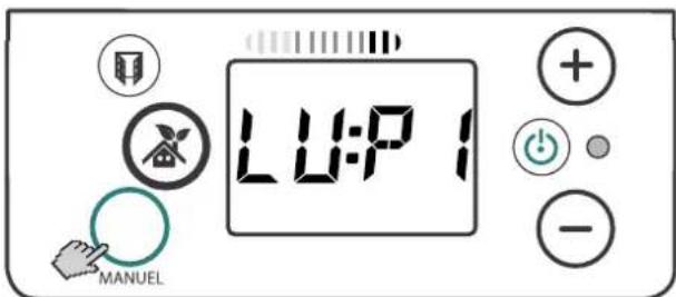
■ Press the WINDOW and AUTOMATIC OPERATION keys simultaneously for three seconds.
ON or OFF is shown.
■ Use the + / - keys to switch to ON if necessary.
■ Confirm with the MANUAL key. Pr is shown.
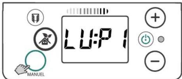
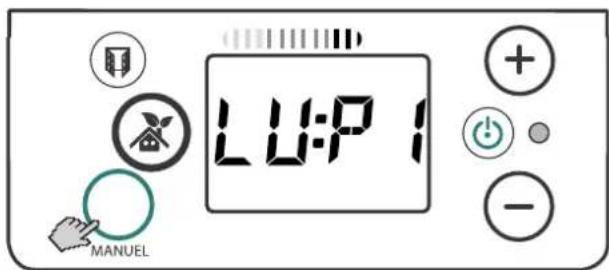
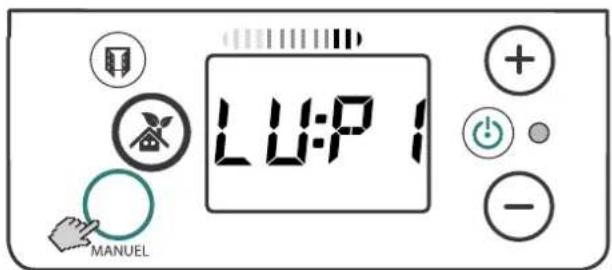
■ Confirm with the MANUAL key. LU:P1 (Monday, Program 1) is shown.
To assign the displayed day a different program, press the + / - keys until the desired program (P1-P6) appears.
■ Confirm with the MANUAL key. MA:P1 (Tuesday, Program 1) is shown.
- Assign other weekdays in the same way. After weekday DI (Sunday) is assigned, Pr is shown.
- Press the – key to switch to EXIT.
■ Press the MANUAL key to return to the main display.
9.5 Activating / deactivating weekly program
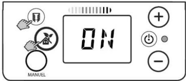
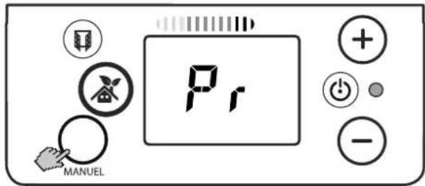
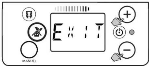
Weekly program On
■ Press the AUTOMATIC OPERATION key.
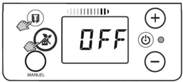
■ Press and hold the WINDOW key and AUTOMATIC OPERATION key simultaneously for three seconds.
ON or OFF is shown.
■ Use the + / - keys to switch to ON.
■ Confirm with the MANUAL key. Pr is shown.
- Press the – key to switch to EXIT.
■ Press the MANUAL key to return to the main display.
Weekly program Off
■ Press the AUTOMATIC OPERATION key.
■ Press and hold the WINDOW key and AUTOMATIC OPERATION key simultaneously for three seconds.
ON or OFF is shown.
■ Use the + / - keys to switch to OFF.
■ Press the MANUAL key to return to the main display.
10. Options
10.1 Window monitoring
i NOTE
The WINDOW MONITORING function is activated at the factory.
The room heating device is equipped with a monitoring function that detects whether unnecessary energy is being consumed due to an open window.
In this case, the window symbol and the green operating display flash. An acoustic warning signal sounds and heating operation is stopped.
Pressing the WINDOW key continues heating operation.
Activating / deactivating the function
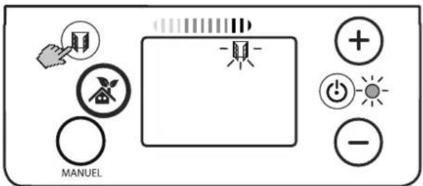
■ Press and hold the WINDOW key for three seconds.
■ The window symbol either appears or disappears on the display.
10.2 Presence detection
i NOTE
Presence detection only in automatic operation.
The controller detects whether a person is in the room. The set comfort temperature remains active for as long as a person is detected. If the room is not in use, the temperature is lowered gradually to save energy:
- By 1°C after 30 minutes, display CF1.
- By 2°C after one hour, display CF2.
- By 3.5°C after more than 2 hours (factory setting).
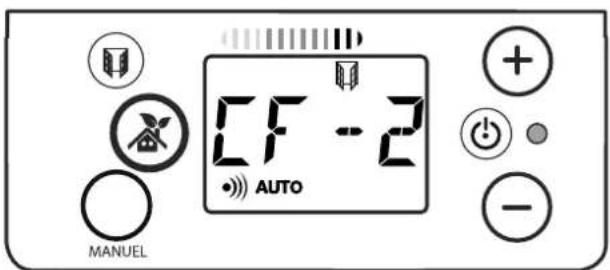
As soon as a person is detected in the room, the switch to comfort temperature takes place.
10.3 Easy key lock
i NOTE
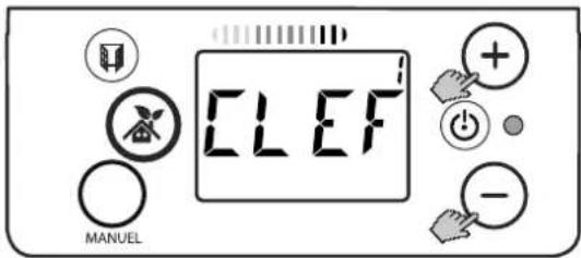
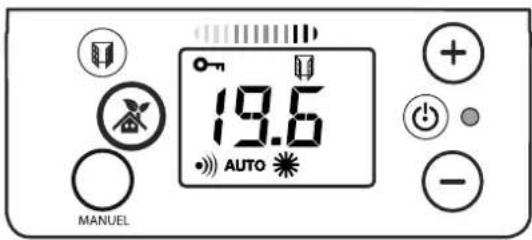
If CLEF appears briefly after any key actuation, key lock is active.
Blocking
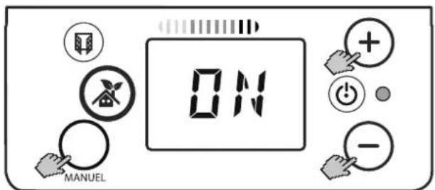
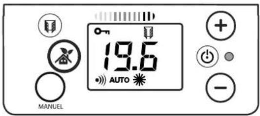
- Press and hold the + key and – key simultaneously for three seconds. CLEF 1 appears briefly, the BLOCK symbol is shown.
Unblocking
- Press and hold the + key and - key simultaneously for three seconds. CLEF 0 appears briefly, the BLOCK symbol disappears.
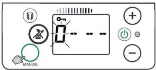
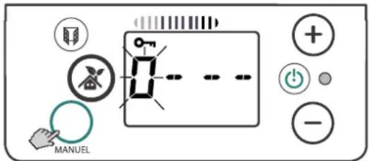
10.4 Key lock with numerical code
Block key entry with a four-digit numerical code.
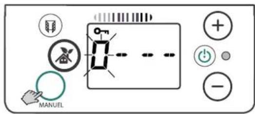
Blocking
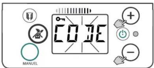
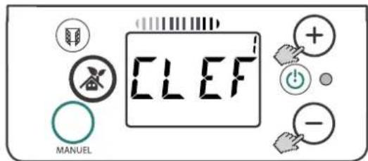
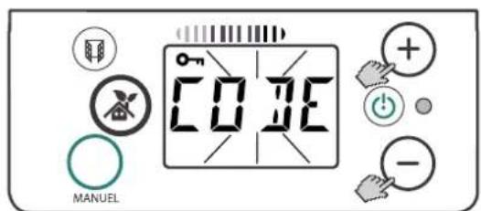
- Press and hold the + key and – key simultaneously for approx. 10 seconds.
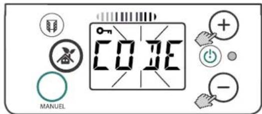
■ CLEF 1 and the BLOCK symbol are shown after 3 seconds. After approx. 7 seconds, CODE flashes. The BLOCK symbol is shown.
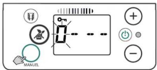
■ Press the MANUAL key. The first CODE digit flashes.
■ Set to the desired code digit with the + / - keys:
■ Press the MANUAL key. The second CODE digit flashes.
■ Set to the desired code digit with the + / - keys:
■ Proceed in the same way for all 4 code digits.
■ Confirm with the MANUAL key. The BLOCK symbol is shown.
Unblocking
- Press and hold the + key and – key simultaneously for approx. 3 seconds. CODE display flashes.
■ Press the MANUAL key. The first CODE digit flashes. - Enter the first code digit with the + / - keys.
■ Press the MANUAL key. The second CODE digit flashes. - Enter the second code digit with the + / - keys.
■ Proceed in the same way for all 4 code digits.
■ Confirm with the MANUAL key. If the code was entered correctly, the OK display flashes.
■ The BLOCK symbol disappears.
i NOTE
If the code was entered incorrectly, the NON display flashes.
10.5 Displaying the current time
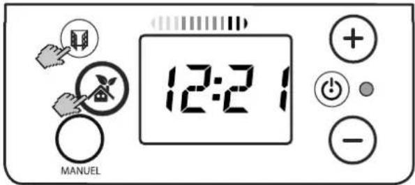
Press the WINDOW and AUTOMATIC OPERATION keys briefly at the same time. The current time is shown briefly.
Incorrect time display
i NOTE
An extended interruption in the power supply can result in an incorrect time display.
Re-setting the time
■ Press the + key The hours display flashes.
■ Use the + / - keys to set the hours.
■ Press the MANUAL key. The minute display flashes.
■ Use the + / - keys to set the minutes.
■ Press the MANUAL key. The weekday display flashes.
■ Use the + / - keys to set the weekday.
■ Press the MANUAL key to return to the main display.
10.6 Backlighting
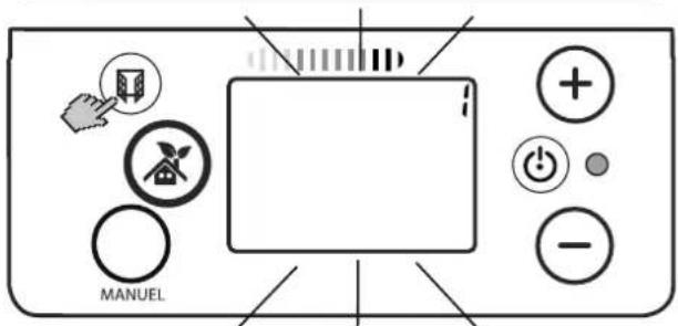
Constant backlighting of the display or limited to approx. 10 seconds.
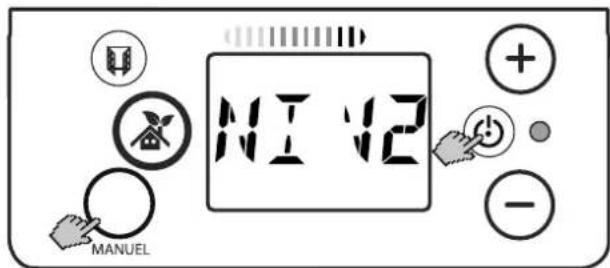
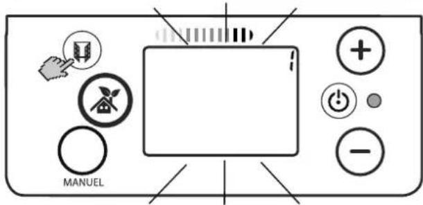
■ Switch off the heating device.
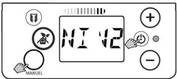
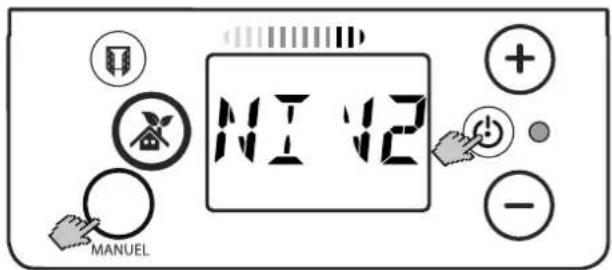
■ Press and hold the MANUAL key and ON/OFF key for three seconds. NIV2 is shown.
■ Press and hold the WINDOW key for three seconds. The backlighting flashes.
■ Set with the + / - keys:
Digit = 1: Restricted backlighting.
Digit = 0: Constant backlighting.
■ Press the MANUAL key until the main display appears.
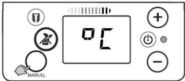
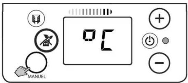
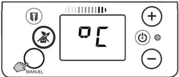
10.7 Temperature unit
Temperature unit display in degrees Celsius or degrees Fahrenheit.
■ Switch off the heating device.
■ Press and hold the MANUAL key and ON/OFF key for three seconds. NIV2 is shown.
■ Press and hold the WINDOW key for three seconds. The backlighting flashes.
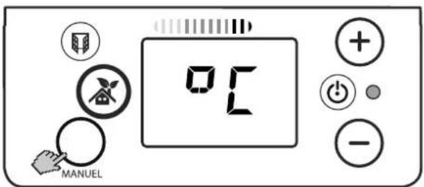
■ Press the MANUAL key until °C appears.
■ Set with the + / - keys:
°C: Display in degrees Celsius.
°F: Display in degrees Fahrenheit.
■ Press the MANUAL key until the main display appears.
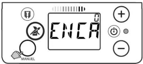
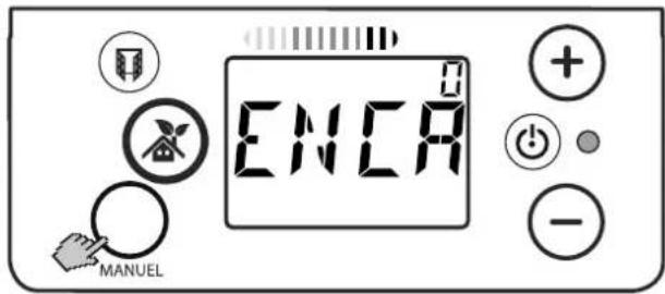
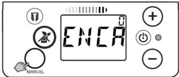
10.8 Temperature setting range
Limit the setting range for the comfort temperature.
Maximum temperature change +/- 2°C.
■ Switch off the heating device.
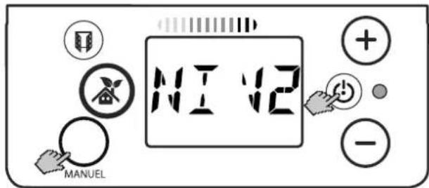
■ Press and hold the MANUAL key and ON/OFF key for three seconds. NIV2 is shown.
■ Press and hold the WINDOW key for three seconds. The backlighting flashes.
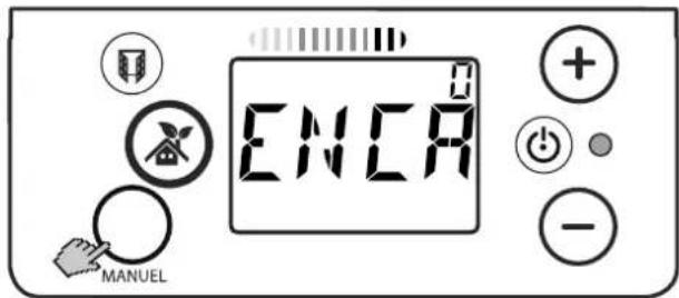
■ Press the MANUAL key until ENCA appears.
Set with the +/− keys:
Digit = 1: Setting range limited to +/- 2°C.
Digit = 0: Setting range not limited.
■ Press the MANUAL key. Main display appears.
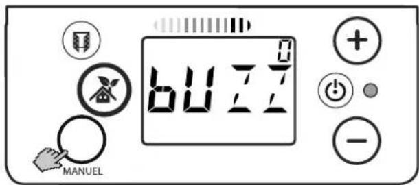
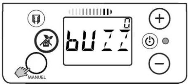
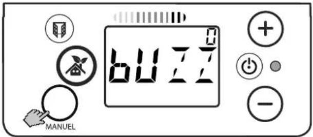
10.9 Audible feedback
Audible feedback in specific operating modes.
i NOTE
The audible feedback for the ON/OFF key can not be deactivated.
■ Switch off the heating device.
■ Press and hold the MANUAL key and ON/OFF key for three seconds. NIV2 is shown.
■ Press and hold the WINDOW key for three seconds. The backlighting flashes.
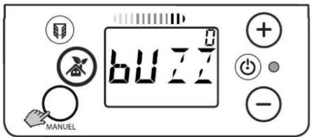
■ Press the MANUAL key. BUZZ appears.
■ Set with the + / - keys:
Digit = 1: Sound on.
Digit = 0: Sound off.
■ Press the MANUAL key until the main display appears.
10.10 Temperature difference Comfort - Eco
The temperature difference between the Comfort temperature and Eco temperature is set to 3.5°C in the factory. This value can be changed as follows.
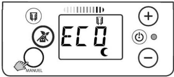
■ Press the MANUAL key until ECO is shown.
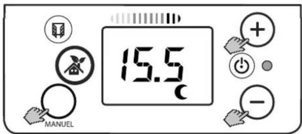
- Press the + / - keys. The ECO temperature value is shown.
■ Press and hold the MANUAL key for three seconds until the temperature value flashes.
■ Change the temperature value with the + / - keys.
■ Press and hold the AUTOMATIC OPERATION key for 3 seconds. MEMO is displayed briefly. The set value is saved.
i NOTE
For energy efficient operation, the temperature difference should be no larger than 3.5^ C.
11. Warranty
This product is supplied with a two-year warranty according to our terms of guarantee.
12. Note on disposal
Do not dispose of the unit with general household waste. The device must be taken to a local waste disposal plant.
13. Technical data
| Unit type FPE050E, | FPE100E | FPE150E,FPE200E | |
| Nominal voltage 1/N, 230 V~ | |||
| Degree of protection IP24, splash-proof | |||
| Dimensions in mm(W x H x D) | 532 x 440 x 113,637 x 440 x 113 | 847 x 440 x 113,1057 x 440 x 113 | |
| Weight 4.4 kg, | 5.3 kg, | 7.0 kg,8.7 kg, | |
| Heat output | |||
| Nominal heat output | P_nom | 0.5 kW, 1.0 kW 1 | 5 kW, 2.0 kW |
| Minimum heat output (guide value) | P_min | 0.5 kW, 1.0 kW 1 | 5 kW, 2.0 kW |
| Maximum continuous heat output | P_max, C | 0.5 kW, 1.0 kW 1 | 5 kW, 2.0 kW |
| Intrinsic consumption | |||
| With nominal heat output | e|_max | 0.0 W 0.0 W | |
| With minimum heat output | e|_min | 0.0 W 0.0 W | |
| In standby state el | SB | 0.5 W 0.5 W | |
| Regulator for heat output | |||
| Electronic room temperature controller with weekly program, window monitoring, presence detection and limitation of the temperature setting range. | |||
2. Montage, installation, distances minimales
ATTENTION!
natural_image
Cross-sectional diagram of a mechanical component with a downward arrow indicating force or direction (no text or symbols)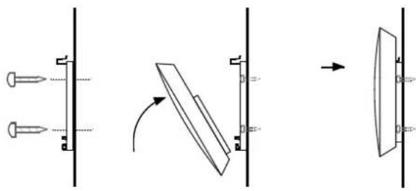
natural_image
Pure mechanical assembly diagram showing pin alignment and rotation process without any text or symbols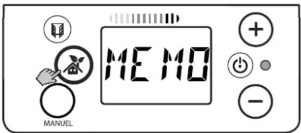
Activer un programme hebdomadaire

Bloquer

Bloquer
i REMARQUE

| Modelli | A(mm) | B(mm) | C(mm) | D(mm) | E(mm) |
| FPE 050E 14 | 5 242 1 | 17 270 10 | 4 | ||
| FPE 100E 22 | 9 177 230 | ||||
| FPE 150E 26 | 3 319 264 | ||||
| FPE 200E 26 | 1 534 262 |
natural_image
Cross-sectional diagram of a mechanical or fluidic component with a downward arrow indicating flow or movement (no text or symbols present)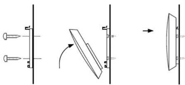
natural_image
Pure mechanical diagram showing pin alignment and cross-sections without any text or symbols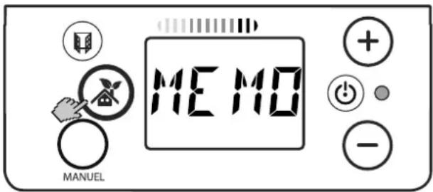

Blocco
Blocco
i NOTA
- DCDimplex
- Programm P1
- Wochenprogramm Ein
- Sperren
- i HINWEIS
- Notes for the user
- i NOTE
- CAUTION!
- NOTE
- Assembly, installation, minimum clearance
- Wall mounting
- Electrical connection
- Connection options
- Overload protector
- Cleaning
- Control description
- Control unit
- Key functions
- On/off
- Automatic operation
- Manual operation
- Window monitoring
- Setting keys + and -
- Display
- Heating operation on display
- Energy efficiency display
- Possible operating modes
- Presence detection
- Automatic operation
- Manual operation
- Weekly program
- Operation
- Switching the heating device on/off
- Manual operation
- Setting the comfort temperature
- Lowering the temperature
- Specify the frost protection temperature
- Automatic operation
- Saving the temperature value permanently
- Weekly program
- Setting the time and weekday
- Fixed set heating programs P1 - P3
- Program P1
- Program P2
- Program P3
- Freely adjustable heating programs P4 - P6
- Assigning the heating program to the weekday
- Activating / deactivating weekly program
- Weekly program On
- Weekly program Off
- Options
- Window monitoring
- Presence detection
- Easy key lock
- Blocking
- Unblocking
- Key lock with numerical code
- Displaying the current time
- Incorrect time display
- Re-setting the time
- Backlighting
- Temperature unit
- Temperature setting range
- Audible feedback
- Temperature difference Comfort - Eco
- Warranty
- Note on disposal
- Technical data
- Montage, installation, distances minimales
- ATTENTION!
- Activer un programme hebdomadaire
- Bloquer
- i REMARQUE
- Blocco
- i NOTA
Brand : DIMPLEX
Model : FPE 200E
Category : Heating