HG4011G - Cooker Atag - Free user manual and instructions
Find the device manual for free HG4011G Atag in PDF.

User questions about HG4011G Atag
0 question about this device. Answer the ones you know or ask your own.
Ask a new question about this device
Download the instructions for your Cooker in PDF format for free! Find your manual HG4011G - Atag and take your electronic device back in hand. On this page are published all the documents necessary for the use of your device. HG4011G by Atag.
USER MANUAL HG4011G Atag
instructions for use
mode d'emploi
Gebrauchsanweisung
natural_image
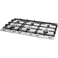
Line drawing of a four-tier gas stove with control knobs (no text or symbols)▶HG40..K/G
▶HG60..K/G
ATAG
Injector diameter and heat input measured on gross C.V.
natural_image
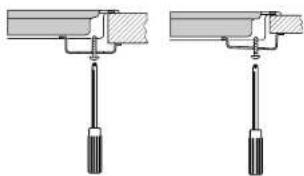
Two mechanical clamping or mounting bracket assembly diagrams with screw base (no text or symbols)fig. 4
In combination with building-in oven With control panel
text_image
2 3 5 3 2 1 4 6 1 4HG60..K/HG60..G
Introduction
When you have read these instructions for use, you will quickly be aware of all the facilities the appliance can offer you. You can read about safety and how you should look after the appliance. In addition you will find environmental tips and instructions that can help to save energy.
Keep the instructions for use and the installation instructions. Any later user of this appliance could benefit from them.
Enjoy your cooking!
Table of contents
■ Appliance information ..... 9
Safety 10 - 11
Before using the appliance ..... 10
Things to watch for 11
- Operating the appliance ....11
Lighting the burners ..... 11
- Use .... 12
Saucepans 12
■ Disposal of packaging and appliance ... 12
■ Maintenance .... 12
Cleaning the appliance....12
■ Installation 13
■ Building-in....14
■ Technical specifications ..... 15
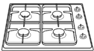
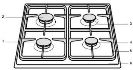
Appliance information HG40..K/HG40..G
1 - control knob for rapid burner 1
2 - control knob for rapid burner 2
3 - control knob for simmer burner 3
4 - control knob for semi-rapid burner 4
5 - enamelled saucepan supports
6 - enamelled or stainless steel drip tray
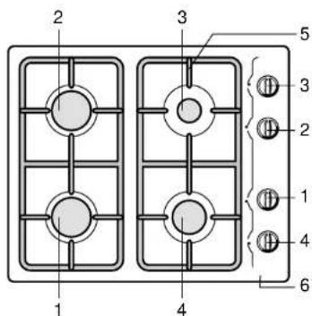
Appliance information HG60..K/HG60..G
1 - control knob for rapid burner 1
2 - control knob for rapid burner 2
3 - control knob for simmer burner 3
4 - control knob for semi-rapid burner 4
5 - enamelled saucepan supports
6 - enamelled or stainless steel drip tray
Control knob symbols:
0 off
high
▲ low
★ spark switch
This appliance complies the regulations concerning
electromagnetic compatibility in directive 89/356/EEC.
Before using the appliance
■ The fitting of the appliance should only be carried out by a registered Corgi gas fitter.
- Only use the appliance if it has been built in correctly. Damage to an incorrectly installed appliance is excluded from the guarantee.
During repair and cleaning the appliance needs to be disconnected from the power supply (electricity and gas). Remove the plug from the wall socket or turn the switch in the metre cupboard to zero (for gas hobs with a spark switch). Turn off the gas tap in the feeder pipe.
■ This cooking appliance is designed for household use. It should only be used for preparing meals.
- When boiling and frying the hob gets hot. Please pay close attention to small children.
■ Grease and oil are flammable when overheated. Stay near the appliance when preparing dishes.
- Do not use the appliance to heat the kitchen. This will produce a damp atmosphere.
- When a gas cooking appliance is being used heat and moisture is produced in the area where the appliance is situated. Make sure that the area is sufficiently ventilated; open natural ventilation openings. When
the hob is used for longer periods extra ventilation may be needed, such as an open window.
■ The burners should not be used without pans. Never place aluminium or plastic trays directly onto a burner.
■ Be careful with the cables of electrical equipment, such as a mixer. These should not be allowed to touch hot burners.
■ The underside of the built-in hob becomes hot. Take care that you do not place any flammable or plastic objects in any drawer under the appliance.
■ Before installing the appliance, check that the gas sort and gas pressure of the gas source are in accordance with what is specified on the model data plate.
Things to watch for
Clean immediately
■ Any spillage should be removed immediately, particularly red cabbage, apple sauce and rhubarb. These can leave permanent spots on the enamel or on stainless steel.
Burning In of the enamel
■ The burners cause the saucepan supports to get extremely hot. Over time the enamel on the support points can burn in. This cannot be prevented and is not covered by the guarantee.
Burner caps
- Check regularly to ensure that the caps of the burners are properly in position on the burner depressions; improper positioning can make it difficult to light the burners, give rise to an irregular gas flame, or damage the burner caps.
Lighting the burners
HG40..G/HG60..G
While keeping the knob of the burner held in, turn the knob to the left and light the burner with a match. The gas flame can now be smoothly adjusted from high to low.
HG40..K
Press the knob of burner in and turn it to the left to the symbol. The spark switch will generate sparks and the burner will light automatically. If the burner fails to light after repeated attempts, check to ensure that the burner cap is properly positioned.
HG60..K
Turn the control knob to the position required, between the high and low settings. Press the control knob. The burner ignites.
Saucepans
The recommended saucepan diameters are: rapid burner ..... minimum 24 cm. semi-rapid burner ..... minimum 20 cm. simmer burner ..... minimum 14 cm.

Wrong: A great deal of heat is lost along the sides of the saucepan.
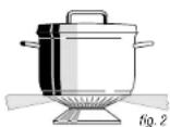
Right: The heat is evenly distributed over the base of the saucepan.
Tip
Cooking with a lid on the pan saves up to 50% on energy. Clean saucepans absorb heat more efficiently.
Packaging and appliances
The packaging of the appliance is recyclable. It is made up off:
-cardboard;
– polyethylene;
– CFK free polystyrene (PS rigid foam).
Please dispose of these materials in a responsible way in accordance with the regulations of your local authority. Your local authority will also be able to give you information about disposing disused household appliances in a responsible way.
Cleaning the appliance
■ Clean the appliance daily with water and a detergent or all purpose cleaner. Avoid using too much water to prevent it entering the burner or ventilation openings.
■ Remove stubborn stains on enamel with a non-abrasive cream or a soft sponge.
Never use scouring powders, aggressive cleaning agents, green scours.
■ Remove stubborn stains on stainless steel with a special stainless-steel cleaning agent. Always polish in the direction of the surface structure of the stainless steel. In this way, you will prevent shiny patches occurring.
If stains cannot be removed, clean the hob with the proprietary HG oven & grill cleaner. Always treat the whole drip-tray, to prevent 'colour differences'. Always treat with a stainless-steel polish/care product afterwards.
■ Scourers contain abrasives that cause scratches on stainless steel. The stainless steel has a surface structure. Scouring or polishing will cause (shiny) patches on the surface. This damage is excluded from the guarantee.
Please note:
Do not drop hot burner caps in cold water. Because of the strong cooling they might get damaged.
Installation
General
The fitting of the appliance should only be carried out by a registered Corgi gas fitter.
Please note:
This appliance is not connected to a flue duct. Take care to ensure that there is sufficient ventilation.
Electrical connection (solely for appliances with a spark switch) 230 V - 50 Hz.
■ The electrical connection must comply with national and local regulations.
■ Wall socket and plug must be accessible at all times.
- If you want to make a fixed connection, ensure that a multi-pole switch with a distance between contacts of 3 mm is installed in the supply cable.
Gasconnection RC 3/8" (ISO 7/1-RC 3/8)
■ The gas connection must comply with national and local regulations.
Amongst other things these regulations instruct that:
- only approved materials are to be used; - only a completely metal hose may be used behind a built-in oven and beneath the hob.
Please note:
The type of gas and the country for which the appliance has been designed are indicated on the ratings plate.
Please note:
We recommend that the hob be connected by means of a fixed pipe. Connection using a specially designed safety hose is also permitted. In all cases the connection tap for the appliance must be positioned such that it is easily accessible, in an adjacent kitchen cupboard, for example.
A metal safety hose must not get kinks in it or get trapped and must not come into contact with moving parts of the kitchen furniture.
■ Before using the appliance for the first time check the connections using water and washing-up liquid to ensure that there are no gas leaks.
Building-in
- Make the cut-out in the work surface. Ensure that there is sufficient space allowed at the sides and at the back.
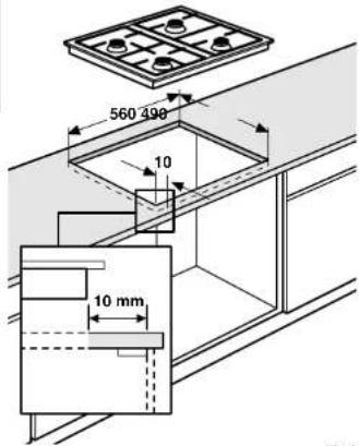
text_image
560 498 10 10 mmfig. 9
Please note:
■ The area to be cut away at the front is measured from 10 mm from the body of the cupboard (cupboard front without door).
2. Make a hole in the side of the kitchen cabinet to enable the gas pipe to be passed through.
3. Place the appliance in the cut-out.
4. Secure the appliance in position.
natural_image
Pure mechanical assembly diagram showing two configurations with screw fasteners (no text or symbols)fig. 4
- Make the gas connection. Check the gas connections with a soap/water mixture (see "Gas Connection").
- Put the plug in the socket (see "Electrical Connection").
- Test to check the appliance is operational.
The building in of the hob in combination with a built-in oven is described in the installation guide for the oven.
Attention!
- The underside of this built-in hob becomes hot. Take care that you do not place any flammable or plastic objects in any drawer under the appliance.
Technical specifications (also see table on cover)
| Type of hob HG40..G HG40..K HG60..G H G60..K | ||||
| Electric: | ||||
| 3-core connection lead ■ | ■ | |||
| Connection AC 230 V - 50Hz - 0.6 VA ■ | ■ | |||
| Spark switch integrated in control buttons ■ | ||||
| Gas: | ||||
| Connection G3/8" ■ | ■ | ■ | ||
| Dimensions (appliance): | ||||
| 580x67x510 wxhxd in mm ■ | ■ | |||
| 580x45x510 bxhxd in mm ■ | ■ | |||
| Dimensions (recess): | ||||
| 560x490 wxd in mm ■ | ■ | ■ |
text_image
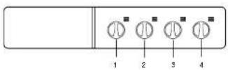
1 2 3 4 5 6HG40..K/HG40..G
natural_image
Two mechanical clamping or mounting assembly diagrams showing bolted components (no text or symbols)fig.4
natural_image
Pure mechanical assembly diagram showing two identical configurations with screws inserted (no text or symbols)Abb. 4