
DCE592 - Electric lift DEWALT - Free user manual and instructions
Find the device manual for free DCE592 DEWALT in PDF.

| Brand | DeWalt |
| Model | DCE592 |
| Type | Electric Vacuum Lifter |
| Voltage | 20 V DC (Li-ion battery pack) |
| Weight | 3.5 lb (1.59 kg) |
| Horizontal Lifting Capacity | 265 lb (120 kg) max. |
| Vertical Lifting Capacity | 132 lb (60 kg) max. |
| Maximum Vacuum Pressure | -12 PSI (-0.83 bar) |
| Operating Temperature | -10 °C to 40 °C |
| Storage Temperature | -10 °C to 60 °C |
| Display | Multi-color LED with pressure and charge indicators |
| Display Modes | PSI and bar (selectable) |
| Recommended Materials | Non-porous (glass, metal, smooth tile) and semi-porous (stone, wood, drywall) |
| Not Recommended Materials | Slate, glass <3 mm, soft plastic, rubber, thin sheets |
| Holding Time Without Power | Up to 5 minutes on non-porous materials |
| Protections | Automatic pump restart, low pressure alarm, low battery shutdown (<20%) |
| Routine Maintenance | Clean air filters and replace foam seal |
| Wear Part | Foam rubber seal (ref. DZE591) |
| Included Accessories | Sunshield, seal protector |
| Optional Accessories | Lifting strap (4-point), additional battery packs |
| Warranty | 3 years (limited) |
Frequently Asked Questions - DCE592 DEWALT
User questions about DCE592 DEWALT
0 question about this device. Answer the ones you know or ask your own.
Ask a new question about this device
Download the instructions for your Electric lift in PDF format for free! Find your manual DCE592 - DEWALT and take your electronic device back in hand. On this page are published all the documents necessary for the use of your device. DCE592 by DEWALT.
USER MANUAL DCE592 DEWALT
English (original instructions) 5
1 Main handle
2 On/off power switch
3 Motor housing
4 Lifter body
5 Strap latches
6 LED screen
7 Mode button
8 Vacuum button
9 Release button
10 Trigger lock button
11 Vacuum pad
12 Foam rubber seal
13 Seal protector
14 Air filters
15 Battery pack
16 Battery release button
17 Sun shade
Composants
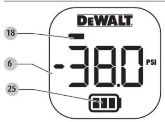
Fig. I Fig. H
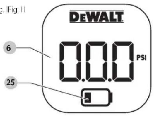
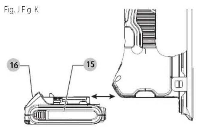
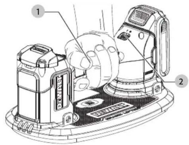
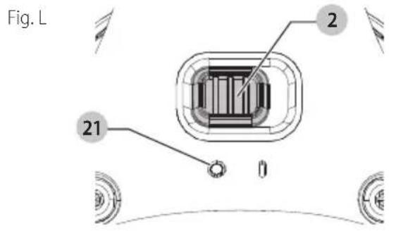
Fig. M
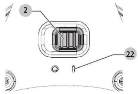
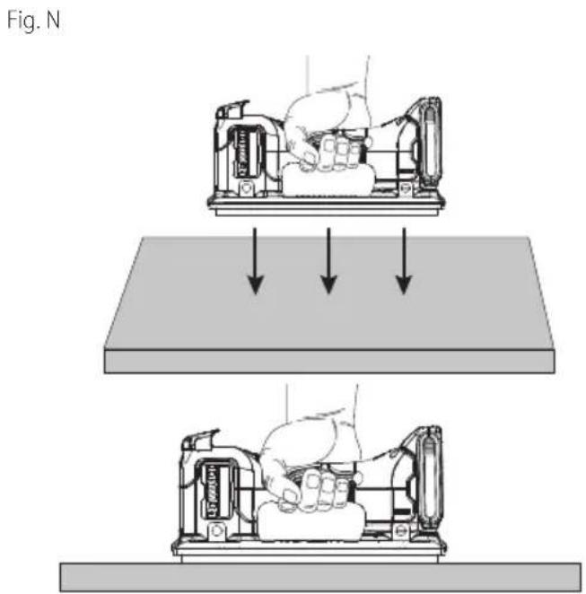
Fig. O
natural_image
Illustration of hands assembling a mechanical component with a curved handle and internal parts (no text or symbols)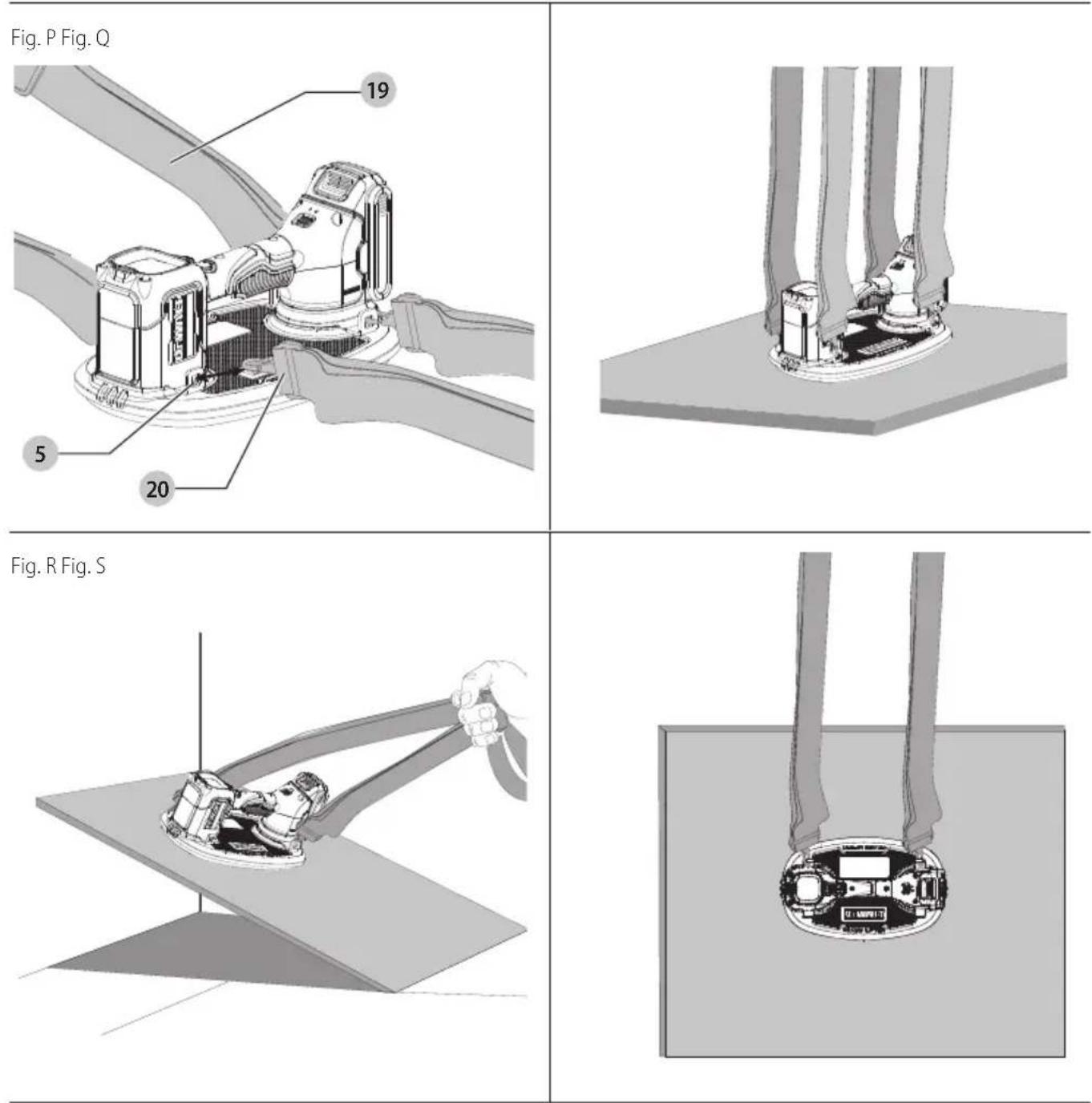
WARNING: Read all safety warnings and all instructions. Failure to follow the warnings and instructions may result in electric shock, fire and/or serious injury.

WARNING: To reduce the risk of injury, read the instruction manual.
Intended Use
The DCE592 is designed for professional lifting, moving, and placing objects like stone pavers, tiles, drywall, furniture and large appliances. For indoor use only.
≤265lb (120kg)
hORiZOnTAl: Material laying flat on ground. A single DCE592 offers up to 265 lbs (120 kg) of horizontal lifting force under ideal conditions.
≤132lb (60kg)

VERTiCAL: Material on its edge.
A single DCE592 offers up to 132 lbs (60 kg) of vertical lifting force under ideal conditions.
For increased lifting capacity use two DCE592 vacuum lifters.
DO nOT use under wet conditions or in presence of flammable liquids or gases.
The DCE592 is a professional power tool.
DO nOT let children come into contact with the tool. Supervision is required when inexperienced operators use this tool.
Technical Specifications
| DCE592 | ||
| Voltage V | DC | 20 |
| Rated Load | ||
| - Horizontally | Ibs / kg 265 / 120 | |
| - Vertically | Ibs / kg | 132 / 60 |
| Operation Temperature 14 °F – 104 °F | (-10 °C – 40 °C) | |
| Operation Humidity <80% | ||
| Storage Temperature 14 °F – 140 °F | (-10 °C – 60 °C) | |
| Storage Humidity <80% | ||
| Weight Ibs 3.5 | ||
Definitions: Safety Alert Symbols and Words
This instruction manual uses the following safety alert symbols and words to alert you to hazardous situations and your risk of personal injury or property damage.
DANGER: Indicates an imminently hazardous situation which, if not avoided, will result in death or serious injury.
WARNING: Indicates a potentially hazardous situation which, if not avoided, could result in death or serious injury.
CAUTION: Indicates a potentially hazardous situation, if not avoided, may result in minor or moderate injury.
(Used without word) Indicates a safety related message.
NOTICE: Indicates a practice not related to personal injury which, if not avoided, may result in property damage.
GENERAL POWER TOOL SAFETY WARNINGS
WARNING: Read all safety warnings, instructions, instructions and specifications provided with this power tool. Failure to follow all instructions listed below may result in electric shock, fire and/or serious injury.
SAVE ALL WARNINGS AND INSTRUCTIONS FOR FUTURE REFERENCE.
The term "power tool" in the warnings refers to your mains-operated (corded) power tool or battery-operated (cordless) power tool.
1) Work Area Safety
a) Keep work area clean and well lit. Cluttered or dark areas invite accidents.
b) Do not operate power tools in explosive atmospheres, such as in the presence of flammable liquids, gases or dust. Power tools create sparks which may ignite the dust or fumes.
c) Keep children and bystanders away while operating a power tool. Distractions can cause you to lose control.
2) Electrical Safety
a) Power tool plugs must match the outlet. Never modify the plug in any way. Do not use any adapter plugs with earthed (grounded) power tools. Unmodified plugs and matching outlets will reduce risk of electric shock.
b) Avoid body contact with earthed or grounded surfaces, such as pipes, radiators, ranges and refrigerators. There is an increased risk of electric shock if your body is earthed or grounded.
c) Do not expose power tools to rain or wet conditions. Water entering a power tool will increase the risk of electric shock.
d) Do not abuse the cord. Never use the cord for carrying, pulling or unplugging the power tool. Keep cord away from heat, oil, sharp edges or moving parts. Damaged or entangled cords increase the risk of electric shock.
e) When operating a power tool outdoors, use an extension cord suitable for outdoor use. Use of a cord suitable for outdoor use reduces the risk of electric shock.
f) If operating a power tool in a damp location is unavoidable, use a ground fault circuit interrupter (GFCI) protected supply. Use of a GFCI reduces the risk of electric shock.
3) Personal Safety
a) Stay alert, watch what you are doing and use common sense when operating a power tool. Do not use a power tool while you are tired or under the influence of drugs, alcohol or medication. A moment of inattention while operating power tools may result in serious personal injury.
English
b) Use personal protective equipment. Always wear eye protection. Protective equipment such as a dust mask, non-skid safety shoes, hard hat, or hearing protection used for appropriate conditions will reduce personal injuries.
c) Prevent unintentional starting. Ensure the switch is in the off position before connecting to power source and/or battery pack, picking up or carrying the tool. Carrying power tools with your finger on the switch or energizing power tools that have the switch on invites accidents.
d) Remove any adjusting key or wrench before turning the power tool on. A wrench or a key left attached to a rotating part of the power tool may result in personal injury.
e) Do not overreach. Keep proper footing and balance at all times. This enables better control of the power tool in unexpected situations.
f) Dress properly. Do not wear loose clothing or jewelry. Keep your hair, clothing and gloves away from moving parts. Loose clothes, jewelry or long hair can be caught in moving parts.
g) If devices are provided for the connection of dust extraction and collection facilities, ensure these are connected and properly used. Use of dust collection can reduce dust-related hazards.
h) Do not let familiarity gained from frequent use of tools allow you to become complacent and ignore tool safety principles. A careless action can cause severe injury within a fraction of a second.
4) Power Tool Use and Care
a) Do not force the power tool. Use the correct power tool for your application. The correct power tool will do the job better and safer at the rate for which it was designed.
b) Do not use the power tool if the switch does not turn it on and off. Any power tool that cannot be controlled with the switch is dangerous and must be repaired.
c) Disconnect the plug from the power source and/or remove the battery pack, if detachable, from the power tool before making any adjustments, changing accessories, or storing power tools. Such preventive safety measures reduce the risk of starting the power tool accidentally.
d) Store idle power tools out of the reach of children and do not allow persons unfamiliar with the power tool or these instructions to operate the power tool. Power tools are dangerous in the hands of untrained users.
e) Maintain power tools and accessories. Check for misalignment or binding of moving parts, breakage of parts and any other condition that may affect the power tool's operation. If damaged, have the power tool repaired before use. Many accidents are caused by poorly maintained power tools.
f) Keep cutting tools sharp and clean. Properly maintained cutting tools with sharp cutting edges are less likely to bind and are easier to control.
g) Use the power tool, accessories and tool bits, etc. in accordance with these instructions, taking into account the working conditions and the work to be performed. Use of the power tool for operations different from those intended could result in a hazardous situation.
h) Keep handles and grasping surfaces dry, clean and free from oil and grease. Slippery handles and grasping surfaces do not allow for safe handling and control of the tool in unexpected situations.
5) Battery Tool Use and Care
a) Recharge only with the charger specified by the manufacturer. A charger that is suitable for one type of battery pack may create a risk of fire when used with another battery pack.
b) Use power tools only with specifically designated battery packs. Use of any other battery packs may create a risk of injury and fire.
c) When battery pack is not in use, keep it away from other metal objects, like paper clips, coins, keys, nails, screws or other small metal objects, that can make a connection from one terminal to another. Shorting the battery terminals together may cause burns or a fire.
d) Under abusive conditions, liquid may be ejected from the battery; avoid contact. If contact accidentally occurs, flush with water. If liquid contacts eyes, additionally seek medical help. Liquid ejected from the battery may cause irritation or burns.
e) Do not use a battery pack or tool that is damaged or modified. Damaged or modified batteries may exhibit unpredictable behavior resulting in fire, explosion or risk of injury.
f) Do not expose a battery pack or tool to fire or excessive temperature. Exposure to fire or temperature above 265 °F (130 °C) may cause explosion.
g) Follow all charging instructions and do not charge the battery pack or tool outside the temperature range specified in the instructions. Charging improperly or at temperatures outside the specified range may damage the battery and increase the risk of fire.
6) Service
a) Have your power tool serviced by a qualified repair person using only identical replacement parts. This will ensure that the safety of the power tool is maintained.
b) Never service damaged battery packs. Service of battery packs should only be performed by the manufacturer or authorized service providers.
SAFETY WARNINGS FOR LIFTERS
WARNING: Read all safety warnings and instructions, and have them for future reference. Failure to adhere to these warnings can result in serious injury and damage to equipment.
a) The DCE592 is not designed or intended for climbing or securing people in any way. Using this product for climbing or any other unintended purpose may result in injury or death.
b) If the DCE592 sealing force begins to noticeably decrease while in use, check the rubber foam seal
for wear and tear or damage. Do not attempt to lift anything with the DCE592 until you have replaced the seal.
c) When not in use keep the seal protected with the seal protector. Store the tool in its protective bag/case or store on smooth surface to avoid denting or tearing the seal.
d) Be wary of high winds when lifting large panels.
e) User should wear safety glasses and steel toe safety shoes.
f) Do not lift overhead, and keep area beneath tool and load clear of people, pets and anything that could be damaged at all times.
g) Keep fingers away from vacuum pad while attaching to load, it may pinch while the foam rubber seal is compressing.
h) Must not use tool as a tether anchor for persons or objects.
i) The load capacity for porous materials will be much lower than for nonporous materials and also if being lifted from the vertical orientation or horizontal orientation.
j) Wet conditions may result in lower load capacity.
k) Care must be taken when lifting slippery materials, especially in a vertical orientation, since they could slide off of the lifter.
1) User should use proper lifting technique and positioning to avoid injury.
m) DO NOT use the tool on flexible materials. This includes thin plastic films and sheets. The suction can bend the material against the gasket and break the vacuum seal, resulting in material dropping/breaking.
n) DO NOT use the tool on 1/8" (3 mm) or thinner glass.
Factors that Alter the Vacuum Lifter's Lifting Capacity and Related Limitations.
Several factors known to affect the vacuum lifter's lifting capacity are noted below.
-
Load rigidity. The rigidity may cause the vacuum lifter and the structure to be loaded unevenly. The rigidity may vary depending on orientation.
-
Load strength. Stress induced by the load's own weight and the stress from the vacuum lifter may damage the load.
-
Load surface conditions. Uneven or rough surfaces may affect the foam rubber seal's ability to attach or maintain a seal. Frictional properties may affect the capacity.
-
Load overhang. As the load extends past the supports of the foam rubber seal, the load may be damaged or deflect and peel away from the foam rubber seal.
-
Angle of the load. The effect of the coefficient of friction between the load and foam rubber seal becomes significant when the load is not horizontal. Angling load could cause load to slide off lifter.
-
Number of DCE592's attached to the load. The capacity varies with the number of vacuum lifter fully attached to the load.
-
Load temperature. Elevated or extremely low temperatures may damage the foam rubber seal or affect the function of the seal. Only operate the lifter between 14 °F (-10 °C) and 104 °F (40 °C).
-
High Altitude Warning: Lifting capacity will be reduced at elevations above 4,000 ft (1220 m). Always ensure load
is secure and balanced by performing a test lift before continuing to move the material.
Operating Practices
- An operator shall not use a lifting device that is tagged "Out of Service" or otherwise designated as nonfunctioning.
- "Out of Service" tags on lifting devices shall not be removed without the approval of the person placing them or a designated person.
- The lifter, when not in use, should be stored at an assigned location.
- Caution should be taken that operation markings, warning labels or tags shall not be removed or defaced. Missing or illegible warning labels or tags shall be replaced.
Additional Safety Information
WARNING: Never modify the power tool or any part of it. Damage or personal injury could result.
WARNING: ALWAYS use safety glasses. Everyday eyeglasses are NOT safety glasses. Also use face or dust mask if cutting operation is dusty. ALWAYS WEAR CERTIFIED SAFETY EQUIPMENT:
• ANSI Z87.1 eye protection (CAN/CSA Z94.3),
• ANSI S12.6 (S3.19) hearing protection,
• NIOSH/OSHA/MSHA respiratory protection.
WARNING: Some dust created by power sanding, sawing, grazing, drilling, and other construction activities contains chemicals known to the State of California to cause cancer, birth defects or other reproductive harm. Some examples of these chemicals are:
- lead from lead-based paints,
• crystalline silica from bricks and cement and other masonry products, and
• arsenic and chromium from chemically-treated lumber.
Your risk from these exposures varies, depending on how often you do this type of work. To reduce your exposure to these chemicals: work in a well-ventilated area, and work with approved safety equipment, such as dust masks that are specially designed to filter out microscopic particles.
- Wear protective clothing and wash exposed areas with soap and water. Allowing dust to get into your mouth, eyes, or lie on the skin may promote absorption of harmful chemicals. Direct particles away from face and body.
- Use the appropriate dust extractor vacuum to remove the vast majority of static and airborne dust. Failure to remove static and airborne dust could contaminate the working environment or pose an increased health risk to the operator and those in close proximity.
• Air vents often cover moving parts and should be avoided. Loose clothes, jewelry or long hair can be caught in moving parts.
CAUTION: When not in use, the seal protector should be reinstalled and the tool placed on the
protector. Leaving tool on its side poses a risk of damaging the seal.
English
The label on your tool may include the following symbols. The symbols and their definitions are as follows:
V....volts
Hz......hertz
min......minutes
or DC.....direct current
Class I Construction (grounded) .../min.....per minute
BPM.....beats per minute
Class II Construction (double insulated)
n_0 ......no load speed
n....rated speed
PSI..... pounds per square inch
⊕ ......earthing terminal
⚠️ ......safety alert symbol
▲......visible radiation—do not stare into the light
E......wearrespiratory protection
...... wear eye protection
......wearhearing protection
read all documentation
do not expose to rain
Batteries and Chargers
The battery pack is not fully charged out of the carton. Before using the battery pack and charger, read the safety instructions below and then follow charging procedures outlined. When ordering replacement battery packs, be sure to include the catalog number and voltage.
READ ALL INSTRUCTIONS
Important Safety Instructions for All Battery Packs
WARNING: Read all safety warnings, instructions, cautionary markings for the battery pack, charger and product. Failure to follow the warnings and instructions may result in electric shock, fire and/or serious injury.
- Do not charge or use the battery pack in explosive atmospheres, such as in the presence of flammable liquids, gases or dust. Inserting or removing the battery pack from the charger may ignite the dust or fumes.
- NEVER force the battery pack into the charger. DO NOT modify the battery pack in any way to fit into a non-compatible charger as battery pack may rupture causing serious personal injury. Consult the chart at the end of this manual for compatibility of batteries and chargers.
- Charge the battery packs only in DEWALT chargers.
• DO NOT splash or immerse in water or other liquids.
- DO NOT allow water or any liquid to enter battery pack.
- Do not store or use the tool and battery pack in locations where the temperature may reach or exceed 104 °F (40 °C) (such as outside sheds or metal buildings in summer). For best life store battery packs in a cool, dry location.
NOTE: Do not store the battery packs in a tool with
the trigger switch locked on. Never tape the trigger switch in the ON position.
- Do not incinerate the battery pack even if it is severely damaged or is completely worn out. The battery pack can explode in a fire. Toxic fumes and materials are created when lithium-ion battery packs are burned.
- Do not expose a battery pack or appliance to fire or excessive temperature. Exposure to fire or temperature above 265 °F (130 °C) may cause explosion.
- Follow all charging instructions and do not charge the battery pack or appliance outside of the temperature range specified in the instructions. Charging improperly or at temperatures outside of the specified range may damage the battery and increase the risk of fire.
- If battery contents come into contact with the skin, immediately wash area with mild soap and water. If battery liquid gets into the eye, rinse water over the open eye for 15 minutes or until irritation ceases. If medical attention is needed, the battery electrolyte is composed of a mixture of liquid organic carbonates and lithium salts.
- Contents of opened battery cells may cause respiratory irritation. Provide fresh air. If symptoms persist, seek medical attention.
- Battery liquid may be flammable if exposed to spark or flame.
- Never attempt to open the battery pack for any reason. If the battery pack case is cracked or damaged, do not insert into the charger. Do not crush, drop or damage the battery pack. Do not use a battery pack or charger that has received a sharp blow, been dropped, run over or damaged in any way (e.g., pierced with a nail, hit with a hammer, stepped on). Damaged battery packs should be returned to the service center for recycling.
Storage Recommendations
The best storage place is one that is cool and dry, away from direct sunlight and excess heat or cold. Store the fully charged battery pack out of the charger.
Battery Pack Cleaning Instructions
Dirt and grease may be removed from the exterior of the battery pack using a cloth or soft non-metallic brush. Do not use water or any cleaning solutions.
Fuel Gauge Battery Packs (Fig. B)
Some battery packs include a fuel gauge. When the fuel gauge button is pressed and held, the LED lights will indicate the approximate level of charge remaining. This does not indicate tool functionality and is subject to variation based on product components, temperature, and end-user application.
Transportation
WARNING: Fire hazard. Do not store, carry, or transport the battery pack so that metal objects can contact exposed battery terminals. For example, do not place the battery pack in aprons, pockets, tool boxes, product kit boxes, drawers, etc., with loose nails, screws,
keys, coins, hand tools, etc. When transporting individual battery packs, make sure that the battery terminals are protected and well insulated from materials that could contact them and cause a short circuit. NOTE: Li-ion battery packs should not be put in checked baggage on airplanes and must be properly protected from short circuits if they are in carry-on baggage.
Shipping the DEWALT FLEXVOLT® Battery Pack
The DEWALT FLEXVOLT® battery pack has a battery cap that should be used when shipping the battery pack.
natural_image
Technical line drawing of a device casing with mounting bracket and internal components (no text or symbols)Attach the cap to the battery pack to ready it for shipping. This converts the battery pack to three separate 20V batteries. The three batteries have the Watt hour rating labeled "Shipping" on the battery pack. If shipping without the cap or in a tool, the pack is one battery at the Watt hour rating labeled "Use."
Example battery pack label:
USE: 120 Wh SHIPPING: 3 x 40 Wh
In this example, the battery pack is three batteries with 40 Watt hours each when using the cap. Otherwise, the battery pack is one battery with 120 Watt hours.
The RBRC® Seal
Please take your spent battery packs to an authorized DEWALT service center or to your local retailer for recycling. In some areas, it is illegal to place spent battery packs in the trash. You may also contact your local recycling center for information on where to drop off the spent battery pack. Do not place in curbside recycling. For more information visit www.call2recycle.org or call the toll-free number in the RBRC® Seal.
RBRC ^® is a registered trademark of Call 2 Recycle, Inc.

Important Safety Instructions for All Battery Chargers
WARNING: Read all safety warnings, instructions, and cautionary markings for the battery pack, charger and product. Failure to follow the warnings and instructions may result in electric shock, fire and/or serious injury.
- DO NOT attempt to charge the battery pack with any chargers other than a DEWALT charger. DEWALT chargers and battery packs are specifically designed to work together.
• These chargers are not intended for any uses other than charging DEWALT rechargeable battery packs. Charging other types of battery packs may cause them to overheat and burst, resulting in personal injury, property damage, fire, electric shock or electrocution. - Do not expose the charger to rain or snow.
-
Do not allow water or any liquid to enter charger.
-
Pull by the plug rather than the cord when disconnecting the charger. This will reduce the risk of damage to the electric plug and cord.
- Make sure that the cord is located so that it will not be stepped on, tripped over or otherwise subjected to damage or stress.
- Do not use an extension cord unless it is absolutely necessary. Use of improper extension cord could result in risk of fire, electric shock or electrocution.
- When operating a charger outdoors, always provide a dry location and use an extension cord suitable for outdoor use. Use of a cord suitable for outdoor use reduces the risk of electric shock.
- An extension cord must have adequate wire size (AWG or American Wire Gauge) for safety. The smaller the gauge number of the wire, the heavier the cord and thus the greater its capacity. An undersized cord will cause a drop in line voltage resulting in loss of power and overheating. The following table shows the correct size to use depending on total length of all extension cords plugged together, and nameplate ampere rating. If in doubt, use the next heavier gauge.
Minimum Gauge for Cord Sets
| Volts | Total Length of Cord in Feet (meters) | ||||
| 120V 25 (7.6) | 50 (15.2) 100 | (30.5) 150 (45.7) | |||
| Ampere Rating | American Wire Gauge | ||||
| More Than Not More | |||||
| Than | |||||
| 0 6 18 | 16 16 14 | ||||
| 6 10 18 | 16 14 12 | ||||
| 10 12 16 | 16 14 12 | ||||
| 12 16 14 | 12 Not Recommended | ||||
- Do not place any object on top of the charger or place the charger on a soft surface that might block the ventilation slots and result in excessive internal heat. Place the charger in a position away from any heat source. The charger is ventilated through slots in the top and the bottom of the housing.
- Do not operate the charger with a damaged cord or plug. Have them replaced immediately.
- Do not operate the charger if it has received a sharp blow, been dropped or otherwise damaged in any way. Take it to an authorized service center.
- Do not disassemble the charger; take it to an authorized service center when service or repair is required. Incorrect reassembly may result in a risk of electric shock, electrocution or fire.
- The charger is designed to operate on standard 120V household electrical power. Do not attempt to use it on any other voltage. This does not apply to the vehicular charger.
- Foreign materials of a conductive nature, such as, but not limited to, grinding dust, metal chips, steel wool, aluminum foil or any buildup of metallic particles should be kept away from the charger cavities and ventilation slots.
• Always unplug the charger from the power supply when there is no battery pack in the cavity.
Charging a Battery (Fig. C, D)
NOTE: To ensure maximum performance and life of Li-Ion battery packs, charge the battery pack fully before first use.
- Plug the charger into an appropriate outlet before inserting battery pack.
- Insert and fully seat battery pack. The charging light(s) will continuously blink indicating that the charging process has started.
For 2-Stage Chargers (DCB1102)
Stage 1 Charging: Blink indicator represents the first charge cycle that charges the majority of the battery's capacity. Stage 2 Charging: Blink indicator represents the remainder, or top off charge process, for the battery to reach full capacity.
- Charging is complete when the charging light(s) remain(s) continuously ON. The battery pack is fully charged and may be removed and used at this time or left in the charger.
NOTE: To remove the battery pack, some chargers require the battery pack release button to be pressed.
WARNING: Only charge batteries in air temperature over 10 °F (4.5 °C) and below 104 °F (40 °C).
Charger will not charge a faulty battery pack, which may be indicated by the charging light(s) staying OFF. Take charger and battery pack to an authorized service center if light(s) stay(s) OFF.
NOTE: Refer to label near charging light(s) on charger for blink patterns. Older chargers may have additional information and/or may not have a yellow indicator light.
Hot/Cold Pack Delay
When the charger detects a battery pack that is too hot or too cold, it automatically starts a Hot/Cold Pack Delay, suspending charging until the battery pack has reached an appropriate temperature. The charger then automatically switches to the pack charging mode. This feature ensures maximum battery pack life.
A cold battery pack may charge at a slower rate than a warm battery pack.
The hot/cold pack delay will be indicated by the red light(s) continuing to blink but with the yellow light continuously ON. Once the battery pack has reached an appropriate temperature, the yellow light will turn OFF and the charger will resume the charging procedure.
Electronic Protection System
Li-ion tools are designed with an Electronic Protection System that will protect the battery pack against overloading, overheating or deep discharge. The tool will automatically turn off and the battery pack will need to be recharged.
Important Charging Notes
-
Longest life and best performance can be obtained if the battery pack is charged when the air temperature is between 65^ F – 75^ F ( 18^ C – 24^ C). DO NOT charge when the battery pack is below 40^ F ( 4.5^ C), or above 104^ F ( 40^ C). This is important and will prevent serious damage to the battery pack.
-
The charger and battery pack may become warm to the touch while charging. This is a normal condition, and does not indicate a problem. To facilitate the cooling of the battery pack after use, avoid placing the charger or battery pack in a warm environment such as in a metal shed or an uninsulated trailer.
- If the battery pack does not charge properly:
a. Check operation of receptacle by plugging in a lamp or other appliance;
b. Check to see if receptacle is connected to a light switch which turns power off when you turn out the lights;
c. If charging problems persist, take the tool, battery pack and charger to your local service center.
- You may charge a partially used pack whenever you desire with no adverse effect on the battery pack.
Charger Cleaning Instructions
WARNING: Shock hazard. Disconnect the charger from the AC outlet before cleaning. Dirt and grease may be removed from the exterior of the charger using a cloth or soft non-metallic brush. Do not use water or any cleaning solutions.
Wall Mounting
Some DEWALT chargers are designed to be wall mountable or to sit upright on a table or work surface. If wall mounting, locate the charger within reach of an electrical outlet, and away from a corner or other obstructions which may impede air flow. Use the back of the charger as a template for the location of the mounting screws on the wall. Mount the charger securely using drywall screws (purchased separately) at least 1" (25.4 mm) long, with a screw head diameter of 0.28–0.35" (7–9 mm), screwed into wood to an optimal depth leaving approximately 7/32" (5.5 mm) of the screw exposed. Align the slots on the back of the charger with the exposed screws and fully engage them in the slots.
SAVE THESE INSTRUCTIONS FOR FUTURE USE
ASSEMBLY AND ADJUSTMENTS
WARNING: To reduce the risk of serious personal injury, turn unit off and remove the battery pack before making any adjustments or removing/installing attachments or accessories. An accidental start-up can cause injury.
Installing and Removing the Sun Shade (Fig. E)
The sun shade 17 can be installed to cover the LED screen 6.
To Install
- Align the two mounting studs 23 on the sun shade 17 with the two mounting holes 24 just above the LED screen 6 on the motor housing 3.
- Firmly press the two mounting studs 23 into the mounting holes 24 until the sun shade 17 sits flush against the motor housing 3.
To Remove
- Firmly pull the sun shade 17 up and away from the motor housing 3.
Connecting a Lifting Strap (Fig. A, P–S)
WARNING: Lifting straps used must be compliant with ASME B30.9. Lifting Hooks must be compliant with ASME B30.10. Rigging Hardware must be compliant with ASME B30.26.
NOTE: User is responsible for sourcing proper lifting strap 19 accessory (sold separately) for use with your tool. Locate the four strap latches 5 around the lifter body 4.
- Secure each of the clips 20 at the ends of the lifting strap 19 into the four strap latches 5.
NOTE: You must connect the lifting strap 19 to each of the four strap latches 5. Or just two of the strap latches 5 depending upon the lifting orientation (see Fig. P–S). - Ensure the lifting straps are not twisted or kinked before lifting.
- Straps must be equal length and with equal tension on them when lifting.
LED Screen (Fig. F-I)
The DCE592 is equipped with a multicolor LED screen 6. The LED screen 6 displays units of pressure, state of battery charge, and state of pressure lights.
Mode button 7 (Fig. A–F)
- Press the mode button 7 to switch until the unit measurement is set to PSI or bar.
Vacuum indicators 18 display green (Fig. F–I)
When the vacuum button 8 is activated, the four vacuum indicators 18 will illuminate green.
- Slide the on/off power switch 2 to the ON position. The DCE592 is now on, and the LED screen 6 display shows 0 PSI/bar and no lights.
- After placing on clean surface of load to be lifted, press the vacuum button 8 once. The vacuum pump will activate and pressure will begin to build to -12 PSI (-0.83 bar). Four green lights illuminate in sequence on the LED screen 6 as the pressure builds to maximum level.
- The LED screen 6 displays the pressure in units of bar or PSI depending on the mode button. The vacuum pump stops running when the pressure reaches -12 PSI (-0.83 bar).
- If vacuum pressure falls below -10.4 PSI (-0.72 bar), the vacuum pump will automatically activate to restore vacuum pressure to -12 PSI (-0.83 bar).
- If the material is too porous to achieve -12 PSI (-0.83 bar) vacuum pressure, the vacuum pump will run continuously.
WARNING: Use extreme caution when lifting in the case because lifting capability is reduced.
- The release button 9 and the on/off power switch 2 are electronically disabled while the vacuum pump is enabled.
Vacuum indicators 18 display red (Fig. F-I)
When the vacuum button 8 is deactivated, the vacuum indicators 18 will illuminate red and blink.
- To release the load, deactivate vacuum pump by pressing the vacuum button 8. The vacuum indicators 18 will illuminate red and blink rapidly.
- Slide trigger lock button 10 forward and press and hold the release button 9 to vent the vacuum pressure and release the load.
- The four vacuum indicators 18 will stop illuminating in sequence as the pressure drops.
LED screen flashing and low battery chime (Fig. I)
- The low battery chime will sound and the LED screen 6 will flash to indicate a low battery condition.
WARNING: When the low battery chime sounds and the LCD screen 6 flashes, the user must immediately set down the load being carried and secure it in place or risk the lifter releasing the load prematurely which may result in serious personal injury and damage to the material being lifted. Once down, press the vacuum button 8 to deactivate vacuum pump, slide the trigger lock button 10 forward and then press and hold the release button 9 to vent the remaining vacuum pressure and release the load. Replace or charge the battery. The DCE592 will not allow a lift to begin if the battery state of charge is below 20%.
- An alert chime will sound if the vacuum pressure falls below -11.7 PSI (-0.81 bar) even if battery is fully charged. NOTE: This may happen below -11.7 PSI (-0.81 bar) on porous materials.
- If pressure is falling the user must immediately set down the load being carried and secure it in place. If pressure is falling, the user should replace the foam rubber seal 12 or reposition the tool to a nonporous section of the material.
State of charge indicator (Fig. H, I)
The DCE592 is equipped with a state of charge indicator. This will display the current level of charge in the battery during use. It does not indicate tool functionality and is subject to variation based on product components, temperature and end-user application.
- The state of charge indicator LEDs 25 will illuminate, indicating the percent of charge in the battery.
- When all three state of charge indicator LEDs illuminate, the battery is fully charged.
- When one state of charge indicator LEDs 25 illuminates, charge is low and then it will flash red when the battery is discharged. Remove the battery and charge it.
State of Charge Indicator Status
| LEVEL OF CHARGE | CHARGE INDICATORLED COLOR | |
| 100% - 75% Yellow | ||
| 50% - 75% Yellow | ||
| 10% - 50% Red | ||
| 10% or less.Low battery shutdown | Red and LED screen flashing. |
OPERATION
WARNING: To reduce the risk of serious personal injury, turn unit off and remove the battery pack before making any adjustments or removing/installing attachments or accessories. An accidental start-up can cause injury.
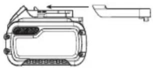
Installing and Removing the Battery Pack (Fig. J)
WARNING: Ensure the tool/appliance is in the off position before inserting the battery pack.
nOTE: For best results, make sure your battery pack is fully charged.
- To install the battery pack 15 into the tool handle, align the battery pack with the rails inside the tool's handle and slide it into the handle until the battery pack is firmly seated in the tool and ensure that it does not disengage.
- To remove the battery pack from the tool, press the battery pack release button 16 and firmly pull the battery pack out of the tool handle.
Proper Hand Position (Fig. K)
WARNING: To reduce the risk of serious personal injury, ALWAYS use proper hand position as shown.
WARNING: To reduce the risk of serious personal injury, ALWAYS hold securely in anticipation of a sudden reaction.
When being used to hand lift material the proper hand position requires one hand on the main handle 1 with your thumb pointing toward the LED screen 6.
Recommended Materials
WARNING: Always test lift item a few inches to ensure you know the capabilities of the DCE592 on the material that you are lifting.
WARNING: Always attach the DCE592 as close as possible to the center of gravity of the load. Ensure the load is balanced during this test lift.
WARNING: Regardless of material being lifted, keep the vacuum pump in the activated position until it is time to safely release the load.
Typical Porous Materials
- Stone • Drywall
- Timber • Concrete
- Plywood • Cement board
CAUTION: When lifting semiporous materials such as perous stone, timber, plasterboard, some OSB board or concrete, ensure the vacuum pump remains in the on position while lifting.
WARNING: When lifting porous loads the vacuum pump may cycle on and off more frequently. Use extreme caution if the vacuum pump cycles on and off frequently or runs continually as it may not be able to reliably lift the load. Lifting capability will be lower.
CANTION: On very porous materials or materials with fine stresses, the DCE592 will not work. This includes some limestone, dry cast concrete, and most OSB board.
Typical Nonporous Materials
- Glass • Finished fiberglass
- Smooth tile • Plastic
- Marble - Metal
Do Not Use On These Materials
WARNING: DO NOT use the DCE592 for any intended purposes.
WARNING: DO NOT lift materials that are not supposed to be lifted.
- Slate • Plastic sheeting
• Glass that is less than 1/8" (3 mm) thick
• Rubber or other flexible materials.
WARNING: Do not use on materials like slate, which is created rock. A seal may be created on the top surface, but the layers can separate causing the rest of the material to come away and the vacuum seal to break.
CANTION: When lifting laminated materials like a lower tops the seal may be created on the top surface, but the layers can separate causing the rest of the material to come away and the vacuum seal to break.
CAUTION: Always remove any protective films from the road area where the DCE592 will be attached.
CAUTION: DO NOT use on very thin or brittle surfaces including glass under 1/8" (3 mm) thick. The vacuum pressure can cause the material to flex and break.
CAUTION: DO NOT use on thin plastic sheets, rubber or other flexible materials. The vacuum pressure can pull the material up against the vacuum release valve in the vacuum lifter. This will prevent the release of the material.
- As the vacuum pressure begins to drop, over time, the vacuum pump will automatically activate until the full vacuum pressure is obtained again.
- Do not disable the vacuum button 8 until you are ready to release the load.
Lifting Materials (Fig. A, K–N)
WARNING: A single DCE592 offers up to 265 lbs (120 kg) or horizontal lifting force and 132 lbs (60 kg) in vertical lifting force under ideal conditions. Refer to the Intended Use section at beginning of this manual.
WARNING: Using the DCE592 while the battery charge is now 20% may result in serious personal injury and damage to the materials being lifted.
WARNING: Clean intended lifting material of any dust or debris before attempting to lift.
WARNING: When lifting any item ensure the vacuum button 8 remains activated while lifting. DO NOT slide the on/off power switch 2 to the OFF position 21.
WARNING: Inspect foam rubber seal for damage and others for obstructions before each lift. If the vacuum pressure falls faster than expected after the motor stops, the foam rubber seal must be replaced.
WARNING: Check the tool weekly for any signs of discharge or wear. Replace damaged parts before using.
WARNING: DO NOT leave the DCE592 unattended with attached to material.
WARNING: DO NOT use the DCE592 near fire or an open flame.
WARNING: DO NOT use the DCE592 continuously for more than two hours. Suction lifters are only suitable for short-term lifting and carrying of loads.
WARNING: DO NOT use the DCE592 with a crane or any similar equipment.
-
Slide the on/off power switch 2 to the ON position 22.
-
Position the DCE592 with the foam rubber seal 12 flush against the surface of the item you want to lift. Ensure load surface is clean and dry, and place the DCE592 above the center of gravity if possible.
NOTE: If using multiple DCE592's then distribute each lifter roughly equal distance from the center of gravity.
NOTE: Do not place the DCE592 over holes and cracks as a vacuum will not be created or will be quickly lost.
NOTE: On some textured surfaces, you may need to apply pressure to the surface with the DCE592 and the foam rubber seal 12 to help create a seal.
- After the vacuum button 8 is pressed the vacuum indicators on the LED screen 6 will illuminate green, and if the battery charge is not below 20%, the tool is ready to use.
NOTE: The DCE592 will not allow a lift to begin if the battery state of charge is low. When the low battery chime sounds and the LED screen 6 flashes, the user must immediately set down the load being carried and secure it in place or risk the lifter releasing the load prematurely.
WARNING: In the event of power failure, the DCE592 will hold non-porous materials for up to five minutes.
The DCE592 will not hold porous materials if power fails.
- Press the vacuum button 8 to start the vacuum pump and create a vacuum seal to the surface of the item you want to lift.
NOTE: You may need to apply some pressure to assist in creating a seal. It may take up to five seconds for the maximum vacuum seal to be created.
- When the vacuum pump reaches maximum sealing range, the vacuum pump will stop and remain activated. The vacuum seal is engaged and you can lift the item. Ensure the load is balanced. If not release and repeat steps above at a more balanced location.
NOTE: When working on porous materials the vacuum pressure may not reach the maximum range and the vacuum pump will keep on running to maintain vacuum pressure.
WARNING: Before each transport of the lifted load, the seconds hold must be checked at a low height in order to avoid injuries due to falling of the lifted load.
WARNING: DO NOT press the vacuum button again at any time during a lift operation as it will disable the pump pressure maintenance ability.
WARNING: When transporting lifted loads, always choose that there is a clear view to your destination to avoid collisions.
WARNING: Do not swing, shake or impact lifted loads.
-
When you are done lifting the item, set it down and secure it in place then press the vacuum button 8. The four vacuum indicators 18 will flash red. The tool can now be released.
-
Slide the trigger lock button 10 forward and then press and hold the release button 9 to release the material. The four vacuum indicators 18 will stop illuminating in sequence as the pressure drops and the pressure level units will show zero.
-
Remove the tool from the material.
MAINTENANCE
WARNING: To reduce the risk of serious personal injury, turn unit off and remove the battery pack before making any adjustments or removing/installing attachments or accessories. An accidental start-up can cause injury.
Your DEWALT power tool has been designed to operate over a long period of time with a minimum of maintenance. Continuous satisfactory operation depends upon proper tool care and regular cleaning.
Proper tool maintenance includes daily and quarterly inspections.
Each day, check for: Cracks, deformation, or damage to the lifter body, proper attainment of vacuum pressure -12 PSI (-0.8 bar), cuts, tears, wear, or damage to the foam rubber seal, any vacuum leaks, vacuum bleed rate, missing control marking and labels.
Quarterly, check for: All daily checks plus loose fasteners, wear deformation, cracking, corrosion damage to structure, damage to controls, and missing safety labels.
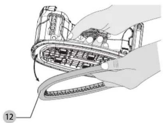
Replacing the Rubber Foam Seal (Fig. O)
WARNING: To reduce the risk of serious personal injury, turn unit off and remove the battery pack before making any adjustments or removing/installing attachments or accessories. An accidental start-up can cause injury.
Replacement rubber foam seals, DZE591, are available from your nearest local dealer or authorized service center.
- Remove the worn or damaged foam rubber seal 12 by pulling it out of the tool.
NOTE: Ensure that the groove where seal resides is clean and free of debris.
- Install a new foam rubber seal 12 into position as shown in Fig. O. Ensure that foam rubber seal 12 is secured into position before using. (Do not use adhesive.)
Cleaning
WARNING: To ensure safe and efficient operation, always keep the electrical appliance and the ventilation slots clean.
WARNING: Never use solvents or other harsh chemicals for cleaning the non-metallic parts of the tool. These chemicals may weaken the materials used in these parts. Use a cloth dampened only with water and mild soap. Never let any liquid get inside the tool; never immerse any part of the tool into a liquid.
WARNING: DO NOT use aggressive cleaning agents for regular cleaning of the suction surfaces.
Ventilation slots can be cleaned using a dry, soft non-metallic brush and/or a suitable vacuum cleaner. Do not use water or any cleaning solutions. Wear approved eye protection and an approved dust mask.
Inspect air filters and replace as needed.
Accessories
WARNING: Since accessories, other than those carried by DEWALT, have not been tested with this product, use of such accessories with this product could be hazardous. To reduce the risk of injury, only DEWALT-recommended accessories should be used with this product.
Recommended accessories for use with your product are available at extra cost from your local dealer or authorized service center. If you need assistance in locating any accessory, please contact DEWALT. Call 1-800-4-DEWALT (1-800-433-9258) or visit our website: www.dewalt.com.
Repairs
The charger and batteries are not serviceable. There are no serviceable parts inside the charger or battery pack.
WARNING: To assure product SAFETY and RELIABILITY, repairs, maintenance and adjustment (including brush inspection and replacement, when applicable) should be performed by a factory service center or an authorized service center. Always use identical replacement parts.
Register Online
Thank you for your purchase. Register your product now for:
- WARRANTY SERVICE: Registering your product will help you obtain more efficient warranty service in case there is a problem with your product.
- CONFIRMATION OF OWNERSHIP: In case of an insurance loss, such as fire, flood or theft, your registration of ownership will serve as your proof of purchase.
- FOR YOUR SAFETY: Registering your product will allow us to contact you in the unlikely event a safety notification is required under the Federal Consumer Safety Act.
Register online at www.dewalt.com/account-login.
Three-Year Limited Warranty
For warranty terms, go to
www.dewalt.com/support/warranty.
To request a written copy of the warranty terms, contact: Customer Service at DEWALT Industrial Tool Co., 701 East Joppa Road, Towson, MD 21286 or call 1-800-4-DEWALT (1-800-433-9258).
LATIN AMERICA: This warranty does not apply to products sold in Latin America. For products sold in Latin America, see country-specific warranty information contained in the packaging, call the local company or see website for warranty information.
FREE WARNING LABEL REPLACEMENT: If your warning labels become illegible or are missing, call 1-800-4-DEWALT (1-800-433-9258) for a free replacement.
natural_image
Technical line drawing of a mechanical component with no visible text or symbols--- o CD.....corriente directa
natural_image
Technical line drawing of a mechanical component with no visible text or symbolsEje Central Lázaro Cárdenas No. 18 - Local (55) 5588 9377 D, Col. Obrera
MERIDA, YUC
Calle 63 #459-A - Col. Centro (999) 928 5038
MONTERREY, N.L.
Av. Francisco I. Madero 831 Poniente - Col. (818) 375 23 13 Centro
PUEBLA, PUE
17 Norte #205 - Col. Centro (222) 246 3714
QUERETARO, QRO
Av. San Roque 274 - Col. San Gregorio (442) 2 17 63 14
SAN LUIS POTOSI, SLP
Col. Santa Fe Alvaro Obregon,
Ciudad de Mexico, Mexico.
C.P 01210
TEL(52) 55 53267100
R.F.C.BDE8106261W7
Registro en Línea
IING: Use of any other battery packs may create a risk of injury and fire.

NOTE: DO NOT charge when the battery pack is below 40^ F ( 4.5^ C) or above 104^ F ( 40^ C). Do not store or use the tool and battery pack in locations where the temperature may reach or exceed 104^ F ( 40^ C).