
VHC010 - Vacuum Cleaner NILFISK - Free user manual and instructions
Find the device manual for free VHC010 NILFISK in PDF.

| Product type | Pneumatic vacuum cleaner |
| Brand | Nilfisk |
| Model | VHC010 |
| Intended use | Cleaning and collection of solid materials in indoor and outdoor locations for commercial use (hotels, schools, hospitals, factories, etc.) |
| Dust category | Combustible dusts (except magnesium dust) in non-ATEX zones |
| Dimensions (L x W x H) | 430 x 440 x 830 mm |
| Weight (without packaging) | 17 kg |
| Power supply | Compressed air (pneumatic) |
| Max. supply pressure | 6 bar |
| Air consumption at 6 bar | 630 NL/min |
| Max. suction (at 6 bar) | 340 mbar |
| Max. air flow (3 m hose, ∅ 40 mm) | 110 m³/h |
| Sound level (LpA) | 70 dB(A) |
| Vibrations (hand/arm) | ≤ 2.5 m/s² |
| Tank capacity | 10 liters |
| Suction inlet diameter | 40 mm |
| Primary filter area | 1.2 m² |
| Compressed air connection | 12 mm |
| Operating conditions | Temperature: -10°C to +40°C; Humidity ≤ 85%; Max. altitude 800 m |
| Storage conditions | Temperature: -10°C to +40°C; Humidity ≤ 85% |
| Safety | Mandatory grounding; antistatic wheels; use of genuine antistatic filters and hoses |
| Maintenance | Replacement of primary and absolute filter; regular cleaning; emptying of tank; use of appropriate PPE |
| Recommended spare parts | Seal (80554900), primary filter (4081701910), motor cooling filter (4081701863), paper bags (107419635/592), DBS bags (4084001606/1208), Safe Bag (4084001573/1209) |
| Warranty | Manufacturer's warranty against manufacturing defects; excluding normal wear, misuse, unauthorized modifications |
Frequently Asked Questions - VHC010 NILFISK
User questions about VHC010 NILFISK
0 question about this device. Answer the ones you know or ask your own.
Ask a new question about this device
Download the instructions for your Vacuum Cleaner in PDF format for free! Find your manual VHC010 - NILFISK and take your electronic device back in hand. On this page are published all the documents necessary for the use of your device. VHC010 by NILFISK.
USER MANUAL VHC010 NILFISK
natural_image
Line drawing of a vacuum cleaner with attached control panel and wheels (no text or symbols)Translation of the original instructions
Table of contents
Table of contents....1
Instructions for use....2
Operator's safety 2
General requirements and precautions for equipment suitable for vacuuming flammable dust .... 3
Residual Risks 5
EC Declaration of conformity 5
Description of the machine ....6
Machine Parts and Labels....6
Packing 6
Commissioning 7
Technical data 8
Operation 9
Maintenance, cleaning and decontamination....11
Preparing for maintenance.... 11
Material unloading system 11
Primary and absolute filter replacement....12
Tightness inspection....13
Recommended Spare Parts....14
Troubleshooting ....15
Warranty and Disposal....16
Warranty....16
Instructions for use
Read the operating instructions and comply with the important safety recommendations identified by the word CAUTION!
Operator's safety

CAUTION!


Before starting the machine, it is absolutely essential to read these operating instructions and to keep them handy for consultation.
The machine can only be used by people who are familiar with the way it works and who have been explicitly authorised and trained for the purpose.
Before using the machine, the operators must be informed, instructed and trained on how to work it and for which substances its usage is permitted including the safe method for removing and disposing of the vacuumed material.

CAUTION!

The use of the machine by people (including children) with limited physical and mental capacities or lacking in experience and knowledge is strictly forbidden, unless they are supervised by a person who is experienced in the use and safe handling of the machine.
Children must be supervised to make sure they will not play with the machine.

CAUTION!

Before using the machine, always check that any hazardous condition has been eliminated and inform the people in charge about any operational fault.
Check that all guards and protections are correctly mounted and that all safety devices are installed and efficient.
Repairs must only be carried out when the machine is at a standstill and disconnected from the electricity and air supply mains. Never ever carry out repairs without having first received the necessary authorization.

CAUTION!

Any changes made by the user without the Manufacturer's explicit authorization shall invalidate the warranty and hold the Manufacturer harmless from any and all liabilities for damages caused by faulty products.
General information for using the machine
Use the machine in accordance with the laws in force in the country where it is used.
Besides the operating instructions and the laws in force in the country where the device is used, the technical regulations for ensuring safe and correct operation must also be observed (Legislation concerning environmental and labour safety,
i.e. European Union Directive 89/391/EC and successive Directives).
Do not perform any operation that could jeopardize the safety of people, property and the environment.
Comply with the safety indications and prescriptions in this instruction manual.
Proper uses
This machine is suitable for commercial use, in hotels, schools, hospitals, factories, shops, offices and apartment hotels for example, for hire and in any case for purposes other than normal domestic use.
This machine is suitable for cleaning and vacuuming solid materials in indoor and outdoor environments.
The machine has been designed to be used by one operator at a time.
This machine consists of a vacuum unit, with an upstream filter unit and a container for collecting the vacuumed material.
Improper Use

CAUTION!

The following use of the device is strictly forbidden:
■ Outdoors in case of atmospheric precipitation.
■ When not placed on horizontal level ground.
■ When the filter unit is not installed.
■ When the vacuum inlet and/or hose are turned to face parts of the human body.
■ Use without the cover on the vacuum unit.
■ When the dust container is not installed.
■ Use without the guards, protective covers and safety systems installed by the manufacturer.
■ When the cooling vents are partially or totally clogged.
■ When the machine is covered with plastic or fabric sheets.
■ Use with the air outlet partially or totally closed.
CAUTION!
The following use of the device is strictly forbidden:
■ When used in narrow areas where there is no fresh air.
■ When the cable or plug is damaged. If appliance is not working as it should, has been dropped, damaged, left outdoors or dropped into water, return it to an authorized service center.
■ Vacuuming liquids with machine not equipped with specific original stopping systems.
- Do not pull or carry by the cord, use the power cord as a handle, do not close a door on cord, or pull cord around sharp edges or corners. Do not run the appliance over the cord. Keep cord away from heated surfaces.
■ Vacuuming the following materials:
- Burning materials (embers, hot ashes, lit cigarettes, etc.).
- Naked flames.
- Combustible gas.
- Flammable liquids, aggressive fuels (gasoline, solvents, acids, alkaline solutions, etc.).
- Explosive dust/substances and/or ones liable to ignite in a spontaneous way (such as magnesium or aluminium dusts, etc.).
Note: Fraudulent use is not admitted.
General recommendations
CAUTION!
If an emergency situation occurs:
For example, accident - fault - filter breakage - fire - etc. Disconnect the machine from the power supply and ask for assistance from qualified personnel.
In case the user comes into contact with the vacuumed product, check the cautions shown on the safety technical sheet of the product, which must be made available from the employer.
[ NOTE ]
Check the place of work and substances tolerated for the machine suitable for liquids.
CAUTION!
The machines must not be used or stored outdoors, or in damp places.
[ NOTE ]
These devices must not be used in corrosive environment.
General requirements and precautions for equipment suitable for vacuuming flammable dust
These machines are suitable to vacuum combustible dust, with the exception of magnesium dust, in areas not classified as ATEX (normal locations). They cannot be used in areas classified as ATEX (Hazardous locations).
CAUTION!
Vacuuming combustible dust presents a risk of fire and explosion. May only be used by trained personnel.
The user must be informed about the dangers related to electric current and static electricity, and the risks deriving from the physical and chemical properties of the substances in the work area.
These vacuum cleaners are designed to vacuum wet and dry particles and clean places and machines occasionally, especially in the foodstuffs, chemical, pharmaceutical and textile industries.
They can also be used to transport dry and wet particles in process machines, especially in the food, chemical and pharmaceutical industries.
They are not designed to be used for ST3 explosion class dust, that is to say dust with value of Kst > 300 bar m/s (ISO 6184/1 – IFA classification: http://staubex.ifa.dguv.de/?lang=e), nor dust with an ignition energy lower than 1 mJ.
These applications are not designed to collect explosives or chemically unstable substances.
These applications are not designed to vacuum fluids with a low flash point (Flash Point lower than 55^ C), nor for incendiary substances ( T < 200^ C).
Precautions before using the machine
Check that the machine specifications have not been modified, otherwise the Declaration of Conformity will no longer be valid.
Static electricity can cause sparks, with the consequent risk of explosion! Therefore, make sure the electrical socket and plug (the ground cable supplied, on non-electric models) are correctly grounded. The machines that are not equipped with this feature, have antistatic wheels: check that these are used on conductive floors.
Using an ohmmeter, check the electrical continuity:
- between the inlet and end of the vacuuming accessories the resistance detected must be less than 100M ( 10^8 )
-
between the collection container and the grounding wire. In this case the measured resistance must be:
-
less than 10 Ω if the components are made of stainless steel (the possible connection points of the electrodes are handles, inlets and wheel supports)
- less than 10 ^6 in the case of plastic container type Safe Pack (the connection point of the electrodes is on the inlet)
Check the integrity and continuity of the ground and equipotential cables (green-yellow protective conductors).
Check for loose of mechanical connections.
The machine must be turned off before connecting it to an energy source. Connect the machine to an energy source outside the ATEX Zone (unclassified zone).
Precautions when using the machine
When replacing the filter, only install original Nilfisk antistatic filters.
Do not use insulating couplings or dust collection hoses.
Do not remove hoses during operation, always wait until the machine has stopped.
Do not use plastic bags for the container. Only Nilfisk original antistatic plastic bags are allowed.
If a pre-separator must be used, check that it is well grounded. Only use antistatic hoses, both for vacuuming and connecting the pre-separator. Do not use the machine to collect large objects or particles because their collision may cause sparks.
Do not rub or hit the floor with steel tools, as they can produce sparks under friction. Only use collectors and suction caps that can be replaced with original Nilfisk antistatic spare parts to clean the floor.
Check the vacuum indicator periodically. This indication is related to the filter clogging level, therefore to the flow speed in hoses. Too slow a speed can cause dangerous stagnation of material in the hose itself.
The user must observe procedures, use methods and accessories for emptying the bin that prevent any alteration of the classification in the Zone where the plant is installed. Only replace accessories supplied by the manufacturer with original spare parts.

CAUTION!

Any accumulation of dust on the machine could represent a potential source of ignition. Clean the surface of the machine regularly.
Precautions during maintenance
Always perform the service operations and checks described in the Instructions Manual.
Check regularly, and in particular while emptying the dust container, that the filters are in good condition (included the safety metallic filter, if equipped), so as to prevent breakage, wear, damages and/or tearing of the filter cloth, which may result in dust dispersion and exhaust emission. This may generate dangerous clouds. Check that the filter is intact before using the machine as follows: vacuum fine inert dust (e.g.: talc, chalk, scagliola...) and make sure it is not blown out of the outlet.
Use antistatic vacuum hoses suitable for the type of material to vacuum. The hoses should not produce sparks or create electrostatic charges caused by the tube rubbing.

CAUTION!

Only use original Nilfisk antistatic hoses and accessories.
The antistatic hoses must be grounded to prevent electrostatic charges. Using an ohmmeter, check for the correct galvanic connection (electrical continuity) between the hoses and the accessories being used. This is to prevent the operator being exposed to fire hazards and the risk of electric shocks.
If necessary, contact Nilfisk service centre only.

CAUTION!

Do not rub non-metal parts with clothes, rags, or fabrics of any kinds (cotton, wool, synthetic, paper, etc.) that can generate dangerous electrostatic charges.
For cleaning non metal parts, use wet clothes or rags in order to reduce the electrostatic charges.
In any case, cleaning procedures must be performed outside the area that has been classified as dangerous for risk of explosion.

CAUTION!

These machines are not suitable for vacuuming aircraft fuel (Jet Fuel).
Residual Risks
After carefully considering the risks that are present in all machine operating phases, necessary measures were adopted in order to eliminate the risks for the operators, as far as possible, and/or limit or reduce the risks deriving from hazards that cannot be completely eliminated at the source.
During operations and/or maintenance, operators are exposed to certain residual risks which, due to the nature of the operations themselves, cannot be completely eliminated. Therefore the installer is responsible for providing additional information and/or hazard signals based on the location of machine installation and the material that is handled.
EC Declaration of conformity
Every machine comes with a EC Declaration of conformity. See fac-simile at the end of this document.
[ NOTE ]
The Declaration of conformity is an important document and should be kept in a safe place to be presented to the Authorities on request.
Description of the machine
Machine Parts and Labels
Figure 1
- Identification plate:
Model code, serial number, EC/UKCA marking, year of manufacture, weight (kg). - Dust container
- Vacuum inlet
- Castor brake lever
- Handle
- Closing band lever
- Air outlet
- Accessory holder
- Vacuum gauge
- Pneumatic system connection fitting.
This machine creates a strong air flow which is drawn in through the vacuum inlet and blows out through the outlet.
Before turning on the machine, fit the vacuum hose into the inlet and then fit the required tool on to the end part (refer to the manufacturer's accessory catalogue or Service Centre).
The diameters of the authorized hoses are indicated in the Technical data table.
The machine is equipped with a primary filter which enables it to be used for the majority of applications.
Packing
All the dispatched equipment has been thoroughly checked before being delivered to the haulage contractor.
Figure 2
| Model A (mm) | B (mm) | C (mm) | kg (*) | ||
| VHC010 550 | 50 | 1200 | 27 |
(*) Weight with packing
NOTE
The installer is responsible for disposing of the packaging according to the applicable laws in force.
NOTE
When the machine arrives, perform a visual inspection together with the carrier, to ensure that the packaging is intact and inform a responsible person if any faults are found.
Any external damage to the containment packaging could in fact create doubts about the actual condition of its content. If there is considerable damage to the containment packaging, immediately inform the Nilfisk technical support service.
Unpacking, moving, and storage
To unpack the vacuum unit, remove the retainers with a hammer and a screwdriver.
Also remove the fastening devices placed by the manufacturer when packing, by using suitable tools.
Release the wheel brakes and remove the machine from the supporting platform, by using a ramp that can provide adequate capacity, and by driving the vacuum cleaner by the handle.
Operate on flat, horizontal surfaces.
The load-bearing capacity of the surface the machine is placed on must be suitable for bearing its weight.

CAUTION!

The manufacturer shall not be liable for any damages caused to the machine during lifting, when the lifting equipment supplied by the manufacturer is not used.
Commissioning
CAUTION!
■ Make sure there is no evident sign of damage to the machine before starting work.
■ Before connecting the machine to the pneumatic supply, make sure the network supplies condensate-free air at the pressure indicated in this manual (see technical data).
■ Regularly check there are no signs of damage, excessive wear, cracks or ageing on the supply hose.
CAUTION!
When the device is operating, do not:
■ Crush, pull, damage or tread on the connecting hose.
■ Only replace the supply hose with one of the same type as the original.
Those responsible for plant safety must ensure that:
■ Prevent any improper use or manoeuvre.
■ Make sure that the safety devices are not removed or tampered with.
■ Check that all maintenance operations are regularly performed;
■ Make sure that no machine part (couplings, holes, etc.) is modified to attach additional devices;
■ Make sure that only original Nilfisk spare parts are used.
[ NOTE ]
The user shall be responsible for ensuring that installation complies with the all relevant local provisions. The equipment must be installed by qualified technicians who have read and understood the instructions herein.
CAUTION!
The air plant must have a filter/reducer since the air that reaches the solenoid valves must be filtered.
The air pressure must be between a maximum 6 bar and a minimum 4 bar.
Grounding instructions
This equipment must be grounded. In case of malfunction or breakdown, grounding provides a path of least resistance for electric current, to reduce the risk of electric shock. Ground the additional yellow/green cable supplied. The machine is also equipped with anti-static wheels: check that they are used on conductive flooring.
CAUTION!
Improper connection of the equipment grounding conductor may result in the buildup of electrostatic charge. If in doubt as to whether the grounding point is working properly, contact a qualified technician.
Optional kits
Various optional kits are available for converting the machine. On request, the machine can be supplied with optional kits already installed. However, they can also be installed at a later date.
Please contact the sales network for further details.
Instructions describing how to fit the optional kits and the relative operation and maintenance manuals are supplied together with the optional kits.
CAUTION!
Use only supplied and authorised genuine spare parts.
Accessories
Various accessories are available; refer to the manufacturer's accessory catalogue.
CAUTION!
Use only genuine accessories supplied and authorised by the manufacturer.
Technical data
| Parameter | Units of measurement | VHC010 |
| Maximum supply pressure (****) bar 6 | ||
| Air consumption (***) (****) NL/min 630 | ||
| Compressed air junction mm 12 | ||
| Max vacuum (***(****) mBar 340 | ||
| Maximum air flow rate (∅40 mm 3 m hose) (***) (****) | m^3/h 110 | |
| Sound pressure level (Lpf)(*) dB(A) | 70 | |
| Vibration, ah (**) m/s | ^2 | ≤2.5 |
| Container capacity L 10 | ||
| Vacuum inlet (diameter) | mm 40 | |
| Allowed hoses | mm 40 | |
| Primary filter surface | m^2 | 1.2 |
(*) Measurement uncertainty KpA < 1.5 dB(A). Noise emission values obtained according to EN-60335-2-69
(**) Total value of vibration output to the operator arm and hand
(***) With supply pressure of 6 bar
(****) See paragraph "Adjusting the supply pressure"
Dimensions
Figure 3
| Model | A (mm) | B (mm) | C (mm) | kg (*) |
| VHC010 | 430 | 440 | 830 | 17 |
[ NOTE ]
■ Storage conditions:
Temperature: -10^ ÷ +40^
Humidity: ≤ 85%
■ Operating conditions:
Maximum altitude: 800 m
(Up to 2,000 m with reduced performances)
Temperature: -10^ ÷ +40^
Humidity: ≤ 85%
Operation
Controls and indicators
Figure 4
1. Vacuum gauge
2. On/Off valve
Inspections prior to starting
Before starting, check that:
■ The filters are installed.
■ The closing band is properly tightened.
■ The vacuum hose and tools have been correctly fitted into the vacuum inlet.
■ The bag or safety container is installed, if applicable.
Do not use the device if the filters are faulty.
Starting and stopping
Lock the castor brakes before starting the vacuum cleaner.
Figure 4
■ Open the valve (2) to start vacuuming.
■ Close the valve (2) to stop vacuuming.
Emergency stopping
Close the on/off valve. The machine stops.
Vacuum gauge
Figure 5
When using the machine, check the flow control:
■ when the machine is operating, the pointer of the vacuum gauge must remain in the green zone (3) to ensure that the speed of the intake air does not drop below the safety value of 20 m/sec;
If the pointer is in the red zone (1) it means that the speed of the air in the vacuum hose is less than 20 m/s, and that the machine is not operating in optimal conditions. Shake or replace the filter.
■ during normal operation conditions, close the vacuum hose, the pointer of the vacuum gauge must switch from the green zone (3) to the red zone (1).
The air speed in the vacuum hose must not be less than 20 m/s.
Condition indicated by the vacuum gauge pointer in the green zone (3).
All machines can be used only with hoses whose diameters comply with the specifications in the "Technical Data" table.

Consult the "Troubleshooting" chapter if faults occur.
Dry applications
[ NOTE ]
The supplied filters and the bag (if applicable) must be installed correctly.
![NILFISK VHC010 - [ NOTE ] - 1](/content/2026/05/750192/images/e51aeeed6e4503c5dc8c5a6abc31104b9e5297a8e12df319e88e466440e5f34b.jpg)
Comply with the safety regulations governing the vacuumed materials.
Supply pressure adjustment
Figure 6
The machine is equipped with a pressure regulator only in case the pressure regulator optional has been purchased.
If you need to mount it, remove the two accessory holders at the back of the machine, and install the regulator holder (1) using the same fixing method. Connect the hose (2) to the fitting (3), and then the pneumatic supply to the fitting (4).
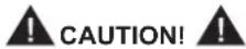
If the adjustment procedure below is not properly respected in each step or if the knob is forced excessively in the direction of the maximum pressure (clockwise), there is a risk of damage to the device and the operator's safety can be compromised.
- Adjust the pressure as required, according to the compressor performances.
- In order to ensure proper performance of the machine, check that the supply piping diameter is adequate, that is to say not less than a nominal diameter of 12 mm.
- Connect the machine to the air supply, then open the on/off valve (5).
For models equipped with pressure regulator
- Adjust the supply air pressure as follows:
- Turn the pressure regulator knob (6) in the direction of the minimum pressure (counter-clockwise) up to the limit switch (regulator closed)
Turn the air regulator knob (6) in the direction of the maximum pressure (clockwise) until it reaches the desired pressure and check with the pressure gauge (7) that it remains stable for at least 3 minutes; press the knob to lock it.
NOTE
If the clockwise rotation reaches the end of the stroke without having reached the desired pressure, and the conditions in point 1 and 2 are met, set a lower supply pressure (see table 1) and repeat the procedure starting from step "a".
| Pressure (Bar) | Consumption (NL/min) | Capacity (m3/h) | Vacuum (mbar) |
| 4 450 105 | 250 | ||
| 5 540 110 | 320 | ||
| 6 630 115 | 340 |
With vacuum hose length: 3 m, diameter: 40 mm
At the end of a cleaning session
■ Close the on/off valve to stop vacuuming.
■ Wind up the connection hose
■ Store the machine in a dry place, out of reach of unauthorised people.
■ Lock the castor brakes.
■ During transport and when not using the machine, close the vacuum inlet with the relevant plug (if equipped).
Maintenance, cleaning and decontamination
Preparing for maintenance
CAUTION!
Disconnect the machine from its power source before cleaning, servicing, replacing parts or converting it to obtain another version/variant.
- Carry out only the maintenance operations described in this manual.
■ Use only original spare parts.
■ Do not modify the machine in any way.
Failure to comply with these instructions could jeopardize your safety. Moreover, such action would immediately void the EC declaration of conformity/ incorporation issued with the machine.
CAUTION!
For maintenance procedures not described in this manual, please contact the manufacturer's technical support or sales network.
CAUTION!
To guarantee the safety level of the machine, only original spare parts supplied by the manufacturer should be used.
CAUTION!
The precautions described below must be taken during all maintenance operations, including cleaning and replacing the primary and absolute filters.
■ To allow the user to carry out the maintenance operations, the machine must be disassembled, cleaned and overhauled as far as is reasonably possible, without causing hazards for the maintenance staff or other people. The suitable precautions include decontamination before disassembling the machine, adequate filtered ventilation of the exhaust air from the room in which is disassembled, cleaning of the maintenance area, and suitable personal protection.
■ The external parts of the machine must be decontaminated by cleaning and vacuuming methods, dedusted or treated with sealant before being taken out of a hazardous zone.
■ All parts of the machine must be considered as contaminated when they are removed from the hazardous zone and appropriate actions must be taken to prevent dust from dispersing.
■ When maintenance or repair procedure are carried out, all the contaminated elements that cannot be properly cleaned, must be eliminated. These elements must be disposed of in sealed bags in accordance with applicable regulations and local laws on the disposal of such material. This procedure must also be followed for filter disposal (primary and absolute filters).
■ Compartments that are not dust-tight must be opened with suitable tools (screwdrivers, wrenches, etc.) and thoroughly cleaned.
■ A check must be carried out by the manufacturer or the personnel of the same at least once a year. For example: Check the air filters to find out whether the air-tightness of the machine has been impaired in any way and make sure that the electric control panel operates correctly.
Material unloading system
CAUTION!
■ Before proceeding with these operations, turn the machine off, and disconnect it from the compressed air connection.
■ Check the machine filtration class.
■ Take care not to raise dust during this operation. Wear a P3 mask and other protective clothing plus protective gloves (PPE) suited to the hazardous nature of the dust collected, refer to the laws in force.
Paper Bag and Safe Bag for dust collection
CAUTION!
■ These operations can only be carried out by trained and qualified personnel who must wear adequate clothing, in compliance with the laws in force.
■ In case of hazardous and/or harmful dust, use only the bags recommended by the manufacturer (see "Recommended spare parts").
■ The bag must only be disposed of by qualified personnel and in compliance with the laws in force.
■ Use only original Nilfisk bags.
■ Only use bags suitable for the machine class you are using.
Figure 7
The machine can be equipped with dust collection bag.
In this case, the machine must be equipped with a specific container and a cap on the side.
If the bag is not properly installed, it could create health risks for people exposed.
[ NOTE ]
The safe bag system is suitable to collect toxic dust to ensure that the user does not come into contact with the product.
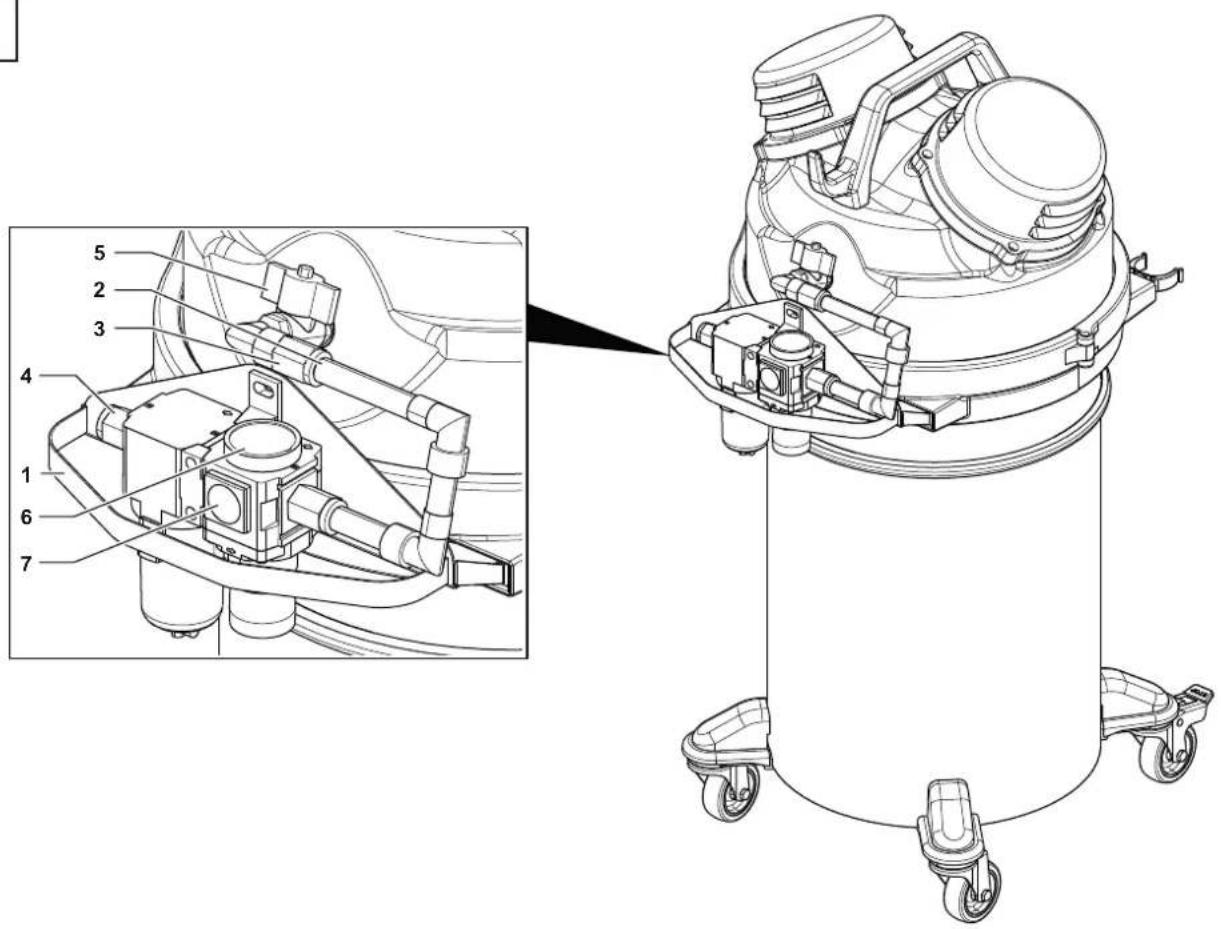
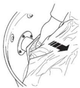
How to replace the Paper Bag
Figure 7
■ Close the inlet by using the relevant cap (if equipped).
■ Release the dust container.
■ Remove the bag and close it with the relevant cap (1) as shown in the figure.
■ Insert a new bag, making sure the bag inlet is sealed.
■ Set the dust container into the machine again.
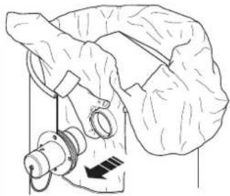
How to replace the Safe Bag
Figure 7
■ Remove and put the vacuum hose in a safe and dust-free place.
■ Close the inlet by using the relevant cap (if equipped).
■ Release the dust container.
■ Close the Safe Bag by pulling the "guillotine" seal (2).
■ Close the plastic bag hermetically using the relevant band (3).
■ Use the sticky tape (4) to close the bottom of the plastic bag.
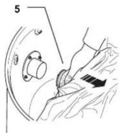
■ Remove the relevant connection (5) of the bag from the vacuum inlet.
■ Insert a new safe bag, making sure the vacuum inlet is well connected to the bag attachment, to grant the sealing.
■ Wrap the plastic bag around the dust container external wall.
■ Place the dust container in the vacuum cleaner.
Primary and absolute filter replacement

CAUTION!

When the machine is used to vacuum hazardous substances, the filters become contaminated, therefore:
■ Work with care and avoid spilling the vacuumed dust and/or material;
■ Place the disassembled and/or replaced filter in a sealed plastic bag;
■ Close it hermetically.
■ Dispose of the filter in accordance with the laws in force.

CAUTION!

Filter replacement is a serious matter. The filter must be replaced with one of identical characteristics, filtering surface and category.
Otherwise the machine will not operate correctly.
Before proceeding with these operations, turn off the machine.

CAUTION!

Before performing these operations, clean the filter as described in the “Maintenance, cleaning and decontamination” paragraph.

CAUTION!

Take care not to raise dust during this operation. Wear a P3 mask and other protective clothing plus protective gloves (PPE) suited to the hazardous nature of the dust collected, refer to the laws in force.

CAUTION!

Reassemble with care to avoid trapping your hands between the vacuum unit and the container. Use gloves that provide protection against mechanical risks (EN 388) with a level of protection CAT. II.

CAUTION!

Do not use the Class H filter again after having removed it from the machine.
Primary filter replacement
Figure 8
■ Release the closing band (1).
■ Lift the deck using the handle (2).
■ Remove the filter (3) by unscrewing the knob (4).
■ Place the filter (3) in a plastic bag, close the bag hermetically and dispose of the filter in accordance with the laws in force.
- Insert a new filter (3) with the same filtering characteristics as the removed one.
■ Lock the filter with the knob (4).
■ Reinstall the deck and lock it with the closing band (1).
Replacing the motor cooling filters
Figure 9
■ Adjust the tightening devices and remove the covers (1)
■ Remove the absolute filter (2) and the related gasket (3).
■ Cover the absolute filter (2) with a plastic bag, close the bag tightly and dispose of the filter in accordance with current legislation.
■ Insert a new absolute filter (2) and the related gasket (3) the same filtering characteristics as the removed one.
■ Refit the covers (1) and lock them into place, using the tightening devices.
Tightness inspection
Hoses check
Make sure that connecting hoses are in a good condition and correctly fixed.
If the hoses are damaged, broken or badly connected to the unions, they must be replaced.
When sticky materials are treated, check for possible clogging along the hose, in the inlet and on the baffle plate inside the filtering chamber.
To clean, scrape the inlet from the outside to remove deposits.
Filtering chamber gasket check for machines equipped with dust container
Figure 10
If the gasket (1) placed between the container and the filtering chamber (3) does not ensure optimal seal, or if tears, cracks, etc. are present, replace the gasket.
Recommended Spare Parts
The following is a list of spare parts that should be kept ready at hand in order to speed up maintenance operations. Refer to the manufacturer's spare parts catalogue when ordering spare parts.
| Item Code | |||
 | Filter chamber gasket / Container 80554900 | ||
 | Primary filter 4081701910 | ||
| Motor Cooling Filter 4081701863 | |||
 | Paper Bag | 1x 5x | |
| 107419635 107419592 | |||
 | Dust Bag - DBS | 1x 5x | |
| 4084001606 4089101208 | |||
 | Safe Bag - SBS | 1x 5x | |
| 4084001573 4089101209 | |||
Troubleshooting
| Problem Cause Remedy | ||
| The machine is unable to collect the material | Clogged primary filter | Use the filter shaker (models with manual filter shaker). Replace it if this is not sufficient. |
| Clogged vacuum hose Check the vacuum hose | and clean it. | |
| Insufficient airflow | Increase air supply pressure. Check the pressure supplied by the pneumatic network is sufficient. | |
| Dust leaks from the machine | The filter is torn Replace it with another of identical type. | |
| Inadequate filter | Replace it with another of a suitable category and check. | |
| Electrostatic current on the machine Missing or inefficient grounding | Check all ground connections. In particular on the vacuum inlet fitting; replace the hose with an antistatic hose. | |
GB
Warranty and Disposal
Warranty
Nilfisk ensures that all its equipment is free from manufacturing or material defects, since each machine is subjected to a final test involving its operation and performances. This guarantees maximum efficiency during the work the machine must carry out. In the event of faults or malfunctions, contact the Manufacturer or your nearest After-Sales Service Centre.
The machine was delivered to the user according to the conditions valid at the time of purchase. For no reason what so ever shall the user be authorized to tamper with the machine.
If the machine does not meet these warranty standards, Nilfisk will correct this non-conformity, at its discretion, by repairing one or more defective parts or replacing one or more parts, provided that the equipment is returned to an authorised Nilfisk After-Sales Service Centre. In all cases, transport shall be borne by the customer. The equipment may not be returned without prior notice and without Nilfisk's consent.
The correction of non-conformities or defects shall constitute the fulfilment of all Nilfisk's liabilities to the customer, whether based on contract, negligence or otherwise in relation to, or arising from, such equipment. The remedies set forth herein are exclusive, and Nilfisk's liability in connection with this sale or anything else done in connection therewith, whether in contract, fault, warranty or otherwise, shall not exceed the price of the equipment or part upon which such liability is based, except as expressly provided herein,
The warranty does not cover repairs due to normal wear and tear, accidents, negligence, misuse or abuse, incorrect installation or use other than that described in the instruction booklet. Hoses and cable breaks are not covered.
The warranty shall also be void if the motor plate is removed or defaced, or if repairs are carried out or attempted by anyone not authorised by Nilflsk.
All attempts by the user or by unauthorized personnel to demount, modify or, more generally, tamper with any part of the machine shall void the guarantee and relieve the manufacturer of all responsibility for damage to either persons or property caused by such action.
The manufacturer shall also be relieved of liability in the following cases:
Incorrect installation; Improper use of the machine by inadequately trained personnel; Use contrary to the regulations in force in the Country of use; Lack of or incorrect scheduled maintenance; Use of non-original spares or spares not specific to the model; Total or partial non-compliance with the instructions; Failure to send the warranty certificate; Exceptional environmental events.
Some States do not allow the exclusion of implied warranties or the limitation of the duration of an implied warranty, so the exclusions or limitations of implied warranties above may not apply. Some States do not allow the exclusion or limitation of incidental or consequential damages, so the above exclusion or limitation of incidental or consequential damages may not apply.
The limited warranties above confer specific legal rights. The customer can enjoy other rights that vary from State to State and as always specified in the sales contract.
6
7
natural_image
Line drawing of a mechanical component with a curved bracket and a black arrow indicating a specific part (no text or symbols present)
natural_image
Illustration of hands adjusting a circular component with an arrow indicating rotation (no text or symbols present)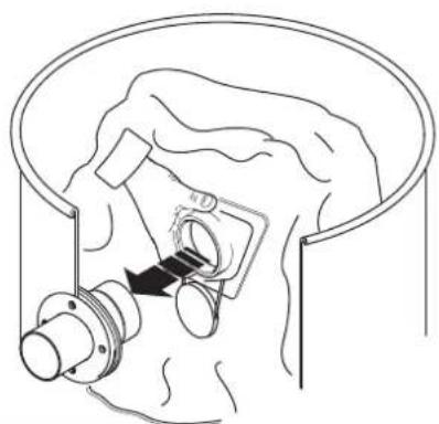
natural_image
Diagram of a mechanical assembly with a valve and housing, no text or symbols present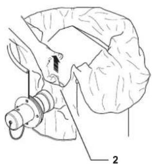
natural_image
Medical illustration showing a surgical procedure on a patient's head (no text or labels)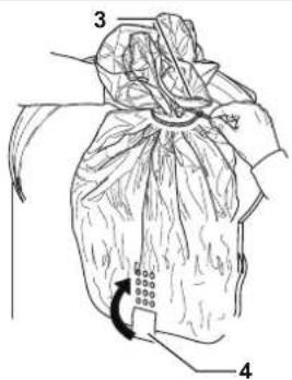
natural_image
Line drawing of a mechanical device with a handle and valve (no text or symbols)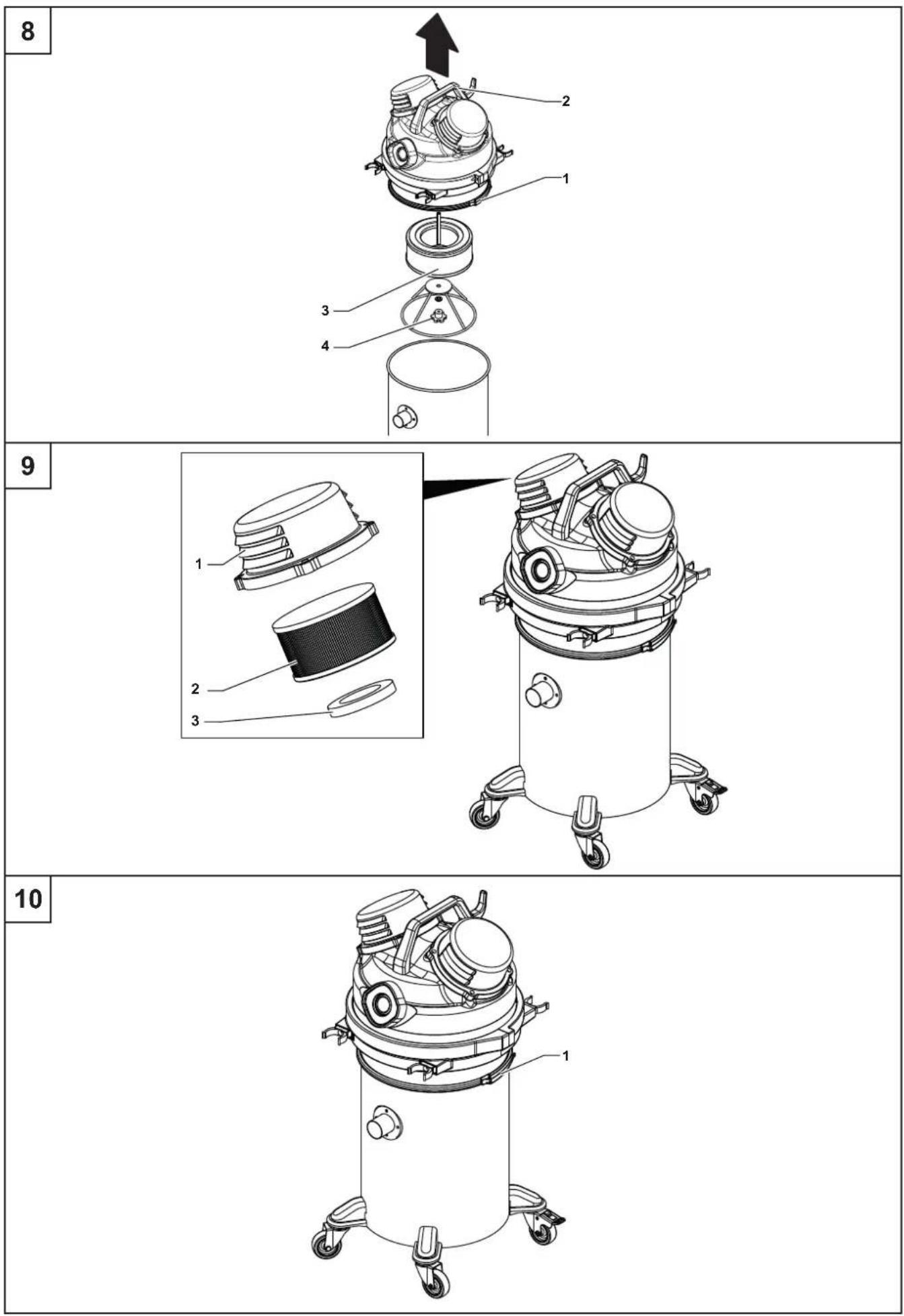
| NILFISK | EUR/UE/EU/EC/E/E/ES/10/AB/16 | ||
| Indication of Coherence modifications System-wide Deutschlandverbindungen Modifications and other societalis/discriture Südenden oder fällende Südenden und sonstige Südenden und sonstige | Part number of conductures abordnungspurjekte Machholerstehrendene lages abstanden Metholers und körliche amniere-dielekpap Aktifische technische Sensitivierung Casteinflussgeschäfte | Credicazione di contrattente elettrico spreggiore Credicazione di contrattente percevole e convenire percevole e convenire societali di sottica societali di sottica | |
| Manufacturer/Vendor/Financier/Enkirk/Transderer/Kemmerzern/Gebe/Enkalk/Transderer/Sommerzern/Protechnik/Enkalk/Transderer/Produktive/Produktive/Suppression/Suppression/Suppression/Suppression/Suppression/Suppression/Suppression/Suppression/Suppression/Suppression/Suppression/Suppression/Suppression/Suppression/Suppression/Suppression/Suppression/Suppression/Suppression/Suppression/Suppression/Suppression/Suppression/Suppression/Suppression/Suppression/Suppression/Suppression/Suppression/Suppression/Suppression/Suppression/Suppression/Suppression/Mathalika/Enkalk/Finanz/Finanz/Finanz/Finanz/Finanz/Finanz/Finanz/Finanz/Finanz/Finanz/Finanz/Finanz/Finanz/Finanz/Finanz/Finanz/Finanz/Finanz/Finanz/Finanz/Finanz/Finanz/Finanz/Finanz/Finanz/Finanz/Finanz/Finanz/Finanz/Finanz/Finanz/Finanz/Finanz/Finanz/Suppression/Suppression/Suppression/Suppression/Suppression/Suppression/Suppression/Suppression/Suppression/Suppression/Suppression/Suppression/Suppression/Suppression/Suppression/Suppression/Suppression/Suppression/Suppression/Suppression/Suppression/Suppression/Suppression/Suppression/Suppression/Suppression/Suppression/Suppression/Suppression/Suppression/Suppression/Suppression/Suppression | Nilfisk A/S, Marmorvej B DK-2100 Copenhagen, DENMARK | [2548] | |
| Place label from production test equipment here. | |||
| Model: | |||
| Type: | |||
| Serial m.: | |||
| Description (Product) / Production / Designation / Designation / Designation / Designation / Designation / Designation / Designation / Designation / Designation / Designation / Designation / Designation / Designation / Designation / Designation / Designation / Designation / Designation / Designation / Designation / Designation / Designation / Designation / Designation / Designation / Designation / Designation / Designation / Designation / Designation / Designation / Designation / Designation / Designation | EN. Dr. RHD. Tanda section under or set sequally, but the other national product when currently add to the following designs and standards. CS. Dr. RHD. Sardine, so, see, with the first element of the product, not a specific, named, and the second element of the product. DE. Dr. RHD. Sardine, to add per Manufacturing for the other products that are used in the product. DA. Dr. RHD. Tanda section under or set in the product, not a specific, no specific, not a specific, no specific product, not a specific, no specific product. ES. Dr. RHD. Tanda section under or set in the product, not a specific, no specific, not a specific, no specific product. ET. Dr. RHD. Tanda section under or set in the product, not a specific, no specific product. FR. Dr. RHD. Tanda section under or set in the product, not a specific, no specific product. FI. Dr. RHD. Tanda section under or set in the product, not a specific, no specific product. NG. Dr. RHD. Tanda section under or set in the product, not a specific, no specific product. NG. Dr. RHD. Tanda section under or set in the product, not a specific, no specific product. NG. Dr. RHD. Tanda section under or set in the product, not a specific, no specific product. NG. Dr. RHD. Tanda section under or set in the product, not an specific, no specific product. NG. Dr. RHD. Tanda section under or set in the product, not an specific, no specific product. NG. Dr. RHD. Tanda section under or set in the product, not an specific, no specific product. NG. Dr. RHD. Tanda section under or set in the product, not an specific, no specific product. NG. Dr. RHD. Tanda sections under or set in the product, not an specific, no specific product. NG. Dr. RHD. Tanda sections under or set in the product, not an specific, no specific product. NG. Dr. RHD. Tanda sections under or set in the product, not an specific, no specific product. NG. Dr. RHD. Tanda sections under or set in the product, not an specific, no specific<|content_end|> | ||
| 2006/42/EC | EN 12/09/2011EN 60335 1:2012+A11:2014+A13:2017+A1.2019+A14:2019+A2.2019+A15:2021EN 60335 2:69:2011 |
| 2014/39/EU | EN 61000 3:2:2014EN 61000-3:3:2013IEC EN 61000-6:2:2019IEC EN 61000-6:4:2019 |
| 2011/65/EU | EN IEC 63000:2018 |
| AuthorizesgnatoryMorten Mathiesen, General Manager IVS, Nifflis SpAMay 23, 2023 |