
H-10903 - Scale Uline - Free user manual and instructions
Find the device manual for free H-10903 Uline in PDF.

User questions about H-10903 Uline
0 question about this device. Answer the ones you know or ask your own.
Ask a new question about this device
Download the instructions for your Scale in PDF format for free! Find your manual H-10903 - Uline and take your electronic device back in hand. On this page are published all the documents necessary for the use of your device. H-10903 by Uline.
USER MANUAL H-10903 Uline
natural_image
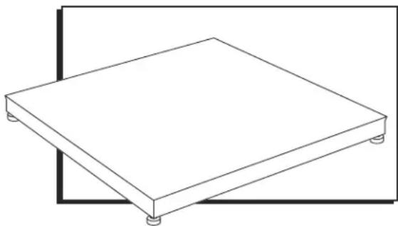
Isometric line drawing of a square plate with four legs, no text or symbols presentINTRODUCTION
SITE SELECTION
Select a site for the floor scale where it is least likely to be damaged by forklifts and other material handling devices. Floor scale load cell weighing elements are prone to overload damage caused by side impacts, falling objects and weight loads that exceed the rated capacity of the scale.
Site should be:
- Level within 1/4".
• Free from vibration. - Clean of debris.
- Out of the way of vehicle traffic patterns, unless installed in a pit while having a rated capacity that exceeds all loaded vehicle weights that could possibly drive onto or contact the scale.
The cable from the floor scale to the digital weight indicator should be run through conduit to protect it against possible damage. Running the instrument cable through conduit is the best method of protection.
UNPACKING
- Inspect your shipment for damage. If you see visible signs of damage, notify carrier at once.
- Remove floor scale from the shipping pallet.
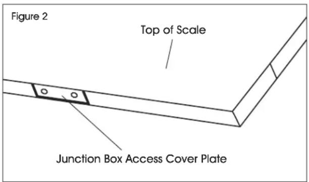
- Unpack the digital indicator. Digital indicator and power cord are located in the junction box in the side of the scale. (See Figure 2)
RAMP INSTALLATION (OPTIONAL)
- Set floor scale in a desired location.
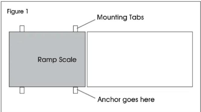
- Position ramp on desired side of the scale. There should be 1/8 - 1/4" gap between the scale and ramp. (See Figure 1)
- To hold ramp in place, drill 1/2 x 3" anchors (not included) through ramp's mounting tabs into the floor.

NOTE: Scale and ramp should not be touching. Contact will impede scale from weighing accurately.
text_image
Figure 1 Mounting Tabs Ramp Scale Anchor goes hereHEIGHT AND LEVEL ADJUSTMENTS
- Unlock the locknuts on all four feet.
- Using a pry bar, lift the weight of the scale base off the scale feet.
- Make adjustments by screwing the feet counterclockwise. All four feet should make firm contact with the floor.
- Do not screw feet counterclockwise more than ten turns.
- Tighten locknuts on feet.
- Check your work.
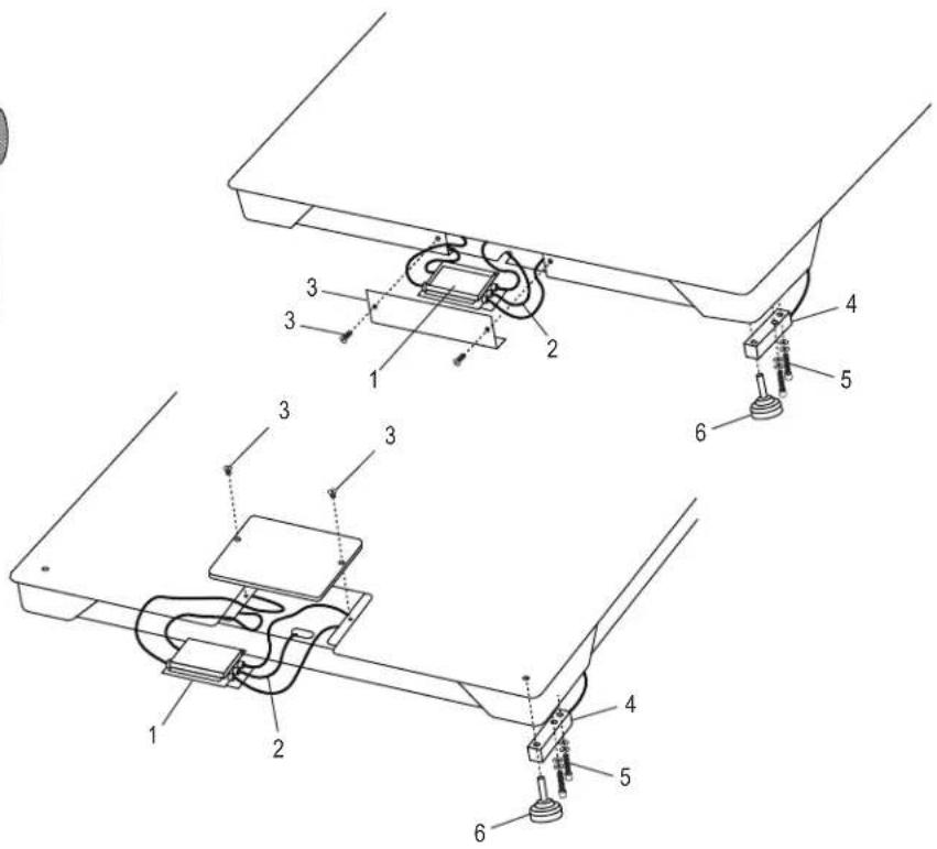
PARTS

text_image
8:8:8:8:8 7
text_image
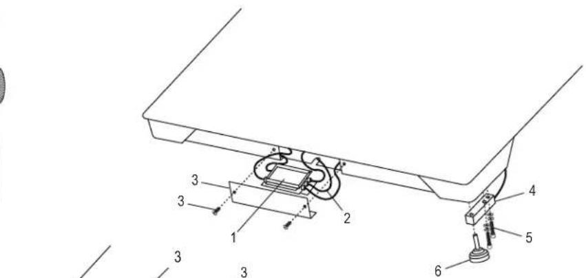
Technical diagram of a mechanical assembly with numbered components for identification
text_image
Technical diagram of a mechanical assembly with numbered components for identification| # | DESCRIPTION | QTY. | ULINE PART NO. | MFG. PART NO. |
| 1 | Stainless Steel Four-Cell Junction Box with Card For 5,000 lb. Scales | 1 | H-5258 | 53042 |
| 2 | LP7510 Stainless Steel Hardwired Connecting Cable | 1 | ---- | 658203 |
| 2 | LP7510 Stainless Steel Hardwired Connecting Cable (Canada Only) | 1 | H-8000-CCBL | 65088UC |
| 3 | Replacement Side Access Cover with Two Bolts | 1 | ---- | 29361 |
| 4 | 2,500 lb. Stainless Steel Shear Beam Load Cell(For 5,000 lb. All-Weather Low Profile Scales) | 4 | H-5261 | 307301 |
| 4 | 5,000 lb. Stainless Steel Shear Beam Load Cell(For 10,000 lb. All-Weather Low Profile Scales) | 4 | H-5262 | 307501 |
| 5 | Stainless Steel Load Cell Bolt and Washer Set for Base | 8 | ---- | 29352 |
| 6 | Feet | 4 | H-4602-SFEET | 50431 |
| 7 | Stainless Steel Display Indicator LP7510B | 1 | H-8000 | 65087U |
| 8 | Power Cord | 1 | H-8001 | 65081U |
ASSEMBLY
SETUP INSTRUCTIONS

NOTE: Floor scale was shipped with the four threaded leveling feet adjusted for a flat and even floor. The leveling feet are locked in place with locknuts. See page 1 for height and level adjustments.
- Remove the screws from the junction box access cover plate and remove the cover plate. (See Figure 2)
text_image
Figure 2 Top of Scale Junction Box Access Cover Plate- Pull indicator out from junction box for use.
- Replace junction box cover plate and secure screws.
CONNECTING POWER

WARNING! Only use the original power plug and battery that came with the scale. Using an alternative power plug or battery could damage the scale.
POWER PLUG
Plug the power plug into a standard 110V outlet.
BATTERY
The scale is equipped with a rechargeable battery.
When the battery voltage is low, a battery indicator symbol will appear in the lower right hand corner of the display.
CHARGING THE BATTERY
When the battery indicator symbol appears in the lower right hand corner of the display, the battery needs to be recharged.
Plug the power plug into the wall to charge the battery. Allow 3-4 hours to fully charge battery. Scale does not need to be turned on.
BATTERY MAINTENANCE
To keep the battery in good condition, simply discharge the battery every month and fully recharge.
If the scale is not used for an extended period of time, remove the battery from the battery compartment to avoid leakage. Store the battery in a sealed bag or box in a dry, temperate environment.
MODEL/SERIAL NUMBER LOCATIONS
The model identification label is located on the side of the frame, next to the junction box access plate. Include both model number and serial number when making inquiries or ordering parts.
CALIBRATION
This scale was calibrated at the factory. DO NOT ATTEMPT TO CALIBRATE THIS SCALE.

WARNING! Breaking, removing or tampering with the lead seal that locks out the calibration switch on the digital weight indicator will void all warranties. Calibration is performed by certified scale service agencies only.
Contact your local weights and measures service agency for calibration services.
DISPLAY INDICATOR AND FUNCTION KEYS
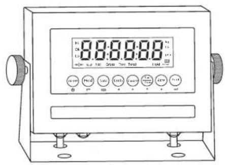
text_image
8:00:00:00 12.5 40.0 14.0 16.0 18.0 20.0 22.0 24.0 26.0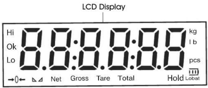
text_image
LCD Display Hi 8.8:0.8.8:8.8 kg Ok 8.8:0.8.8:8.8 pcs Lo →0← △△ Net Gross Tare Total Hold LobatLCD FUNCTIONS
| LCD | INSTRUCTION |
| Hi Overload | |
| OK Ok | |
| Lo Underload | |
| →0← | Weight is zero |
| The weighing data is stable | |
| Net Net weight | |
| Gross Gross weight | |
| Tare Tare | |
| Total Go to accumulation mode | |
| Hold Data hold | |
| kg | kg |
| lb lb | |
| Pcs Show the counting status | |
| Lobat | Battery Indicator |
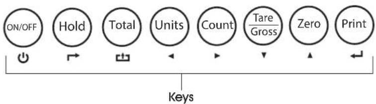
flowchart
graph LR
    A["ON/OFF"] --> B["Hold"]
    B --> C["Total"]
    C --> D["Units"]
    D --> E["Count"]
    E --> F["Tare/Gross"]
    F --> G["Zero"]
    G --> H["Print"]
    H --> I["Keys"]
KEY FUNCTIONS
| KEY | KEY NAME | KEY FUNCTION |
 | Power On/Off Press for two seconds to power on or power off. | |
 | Hold Weight | Four hold functions; can be changed in parameter settings.See Operation section on page 3 for instructions. → Toggle |
 | Accumulation | Works with PRINT key to perform the accumulation function and check the accumulation result. □ Save |
 | Lb/Kg Convert Convert between lb and kg. | Left |
 | Counting Counting Operation. | Right |
 | Tare/Gross Weight | Press key once to tare. Press key again to get Gross Weight. ▼ Down |
 | Zero Zeros the weight within tolerance. | Up ▲ |
 | Works with ZERO, TARE, ON/OFF keys to perform functions. ← Enter |
OPERATION
POWER ON/OFF
- Pressthe ON/OFF key for two seconds to turn the scale on or off.
- When turning on, the indicator will show 000000-999999 before entering weighing mode.
- Check that the LED display and the status lights are working properly.
ZERO
INITIAL ZERO SETTING
When turning the scale on, if the weight on the display indicator is within the initial zero tolerance, the indicator will show .
MANUAL ZERO SETTING
- Wait for the scale to stabilize.
- Press the ZERO key. The display will show zero weight.
HOLD FUNCTIONS
There are four different hold functions.
PEAK HOLD
Captures the highest weight.
- Press the HOLD key then add weight to the scale.
- The highest recorded weight will show on the display until a higher weight is placed on the scale.
MANUAL HOLD
Captures and holds the current weight so it will not change/fluctuate.
- While weighing, press HOLD. The current weight will show on the display until HOLD is pressed again.
AUTO HOLD
If the current weight is above 20d (20 x division) and is stable, the current weight will be displayed for three seconds then go back to general weighing.
- Pressing the HOLD key is unnecessary. Auto Hold is done automatically when the scale is stable.
AVERAGE HOLD
Used for animal weighing. The indicator will display the average weight sampled for three seconds.
- Add livestock to scale and press HOLD.
- "LOC" will be displayed for three seconds. Then the average weight will be displayed.
- Press HOLD again to exit holding mode.
TARE/GROSS
- Press the TARE/GROSS key.
- The indicator will show the net weight. The Net and Tare function lights will light up.
- Press the TARE/GROSS key. Zero the weight.
- The indicator will display the gross weight.
ACCUMULATION
- Zero the weight. Load weight until the scale stabilizes.
- Press the TOTAL key to enter accumulation mode.
- Total function light will light up. Display will read n 001 then will display the loaded weight.
- Unload the weight. Zero the weight. Load the second weight until the scale stabilizes.
- Press the TOTAL key. The display will read n002, then display the second loaded weight.
- Repeat a maximum of 999 times.
CHECK THE ACCUMULATION
- Press and hold the PRINT key. Press the TOTAL key.
- Display will read n**, then will show total weight.

NOTE: There are eight digits total. The display shows the first four digits, then the last four digits. For example, when the first four digits displayed are "0012" and the last four digits displayed are "34,56," the weight is "1234.56."
EXIT ACCUMULATION
- When the indicator shows the last four digits, press and hold the TOTAL key. The indicator will read cir n.
- Press the PRINT key to exit. If you want to clear the total weight, press the ZERO or TARE key. The indicator will read cir y.
- Press the PRINT key to clear the total weight and exit accumulating mode.
- If the weight is stable, connect the scale to the printer.
- Press the PRINT key.

NOTE: While in tare mode, print with tare. If the scale shows a negative weight, printing is not allowed.
OPERATION CONTINUED
COUNTING
Use this mode to count parts of uniform weight.
- In weighing mode, remove all weight from the platform.
- Press the COUNT key to enter the counting mode. PCS 0 will be shown on the display.
- Press the ZERO key to change the sample quantity -5, 10, 20, 50, 100, 200 or 500 units.
-
Place the sample quantity of the item being counted on the scale platform and press the PRINT key. Sample quantity will be shown on the display.
-
Place remaining objects on the platform. The total quantity will be shown on the display.
- Press the COUNT key to return to weighing mode.
- To weigh different weights, at weighing mode put the item on the scale and press the COUNT key. The indicator will read 0.
- Press and hold the Count key. Press the ON/OFF key. The indicator will show PCS 0.
- Press the ZERO key and input the sample quantity.
- Press the PRINT key to enter. Repeat steps 2 and 3.
TROUBLESHOOTING
POSSIBLE TARE OPERATION CODES
| ERROR REASON SOLUTION | ||
| UUUUUUUU Weight overload. | Bad connection with load cell. | Reduce the weight. |
| Load cell has quality problem. | Check load cell connection. | |
| Inspect load cell. Check input and output. | ||
| nnnnnnn Calibration error. | Bad connection. | Check that scale is level. |
| Load cell has quality problem. | Check load cell connection. | |
| Inspect load cell. Check input and output. | ||
MAINTENANCE
- Maintain a good connection between load cell's instrument cable connector and indicator.
- Keep indicator away from strong electric and magnetic fields.
• Power off the indicator during electrical storms.
- Power off the indicator before plugging and unplugging.
natural_image
Isometric line drawing of a square plate with four legs, no text or symbols presentINTRODUCCIÓN
SELECCIÓN DEL ÁREA
text_image
Technical diagram of a mechanical assembly with numbered components for identification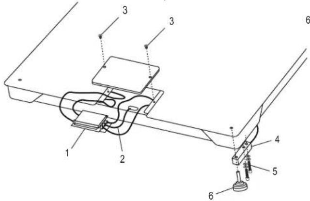
text_image
Technical diagram of a mechanical assembly with numbered components, likely for assembly or maintenance instructions.natural_image
Isometric line drawing of a rectangular plate with four legs and a small base, no text or symbols present.INTRODUCTION
CHOIX DE L'EMPLACEMENT
text_image
8:88:88 7
text_image
Technical diagram of a mechanical assembly with numbered components, likely illustrating a device or component layout.text_image
0.0:0.0:0.0 1.0 2.0 3.0 4.0 5.0 6.0 7.0 8.0 9.0 10.0 11.0 12.0 13.0 14.0 15.0 16.0 17.0 18.0 19.0 20.0 21.0 22.0 23.0 24.0 25.0 26.0 27.0 28.0 29.0 30.0 31.0 32.0 33.0 34.0 35.0 36.0 37.0 38.0 39.0 40.0 41.0 42.0 43.0 44.0 45.0 46.0 47.0 48.0 49.0 50.0 51.0 52.0 53.0 54.0 55.0 56.0 57.0 58.0 59.0 60.0 61.0 62.0 63.0 64.0 65.0 66.0 67.0 68.0 69.0 70.0 71.0 72.0 73.0 74.0 75.0 76.0 77.0 78.0 79.0 80.0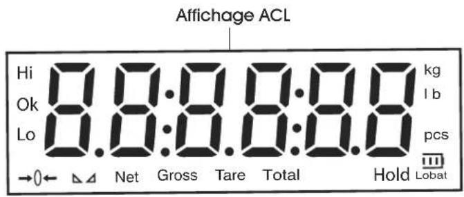
text_image
Affichage ACL Hi 8.0:8.0:8.0 kg Ok 8.0:8.0:8.0 pcs Lo 8.0:8.0:8.0 pcs →0← △△ Net Gross Tare Total Hold LobatFONCTIONS ACL


