
XC802100 - Compressor Campbell Hausfeld - Free user manual and instructions
Find the device manual for free XC802100 Campbell Hausfeld in PDF.


User questions about XC802100 Campbell Hausfeld
0 question about this device. Answer the ones you know or ask your own.
Ask a new question about this device
Download the instructions for your Compressor in PDF format for free! Find your manual XC802100 - Campbell Hausfeld and take your electronic device back in hand. On this page are published all the documents necessary for the use of your device. XC802100 by Campbell Hausfeld.
USER MANUAL XC802100 Campbell Hausfeld
CH CAMPBELL HAUSFELD
Electric Air Compressor
Operating Instructions and Parts Manual
natural_image
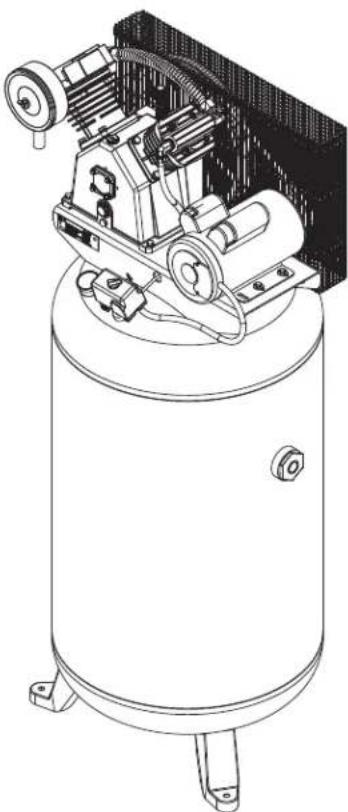
Technical line drawing of an industrial air compressor unit with cooling fan and mounting base (no text or symbols)Models: CE5003 and XC802100
EN

CAMPBELL HAUSFELD.
Please read and save these instructions. Read carefully before attempting to assemble, install, operate or maintain the product described.
Protect yourself and others by observing all safety information. Failure to comply with instructions could result in personal injury and/or property damage! Retain instructions for future reference.
REMINDER: Keep your dated proof of purchase for warranty purposes! Attach it to this manual or file it for safekeeping.
For parts, product & service information visit www.campbellhausfeld.com or call 888-895-4549
Model #: ____
Serial #: ____
Purchase Date: ____
Campbell Hausfeld MAT Industries, LLC Long Grove, IL 60047
BEFORE YOU BEGIN
Description
Air compressor units are intended to provide compressed air to power pneumatic tools, operate spray guns and supply air for pneumatic valves and actuators. The pumps supplied with these units have oil lubricated bearings. A small amount of oil carryover is present in the compressed air stream. Applications requiring air free of oil vapor should have the appropriate filters installed. Any other use of these units will void the warranty and the manufacturer will not be responsible for problems or damages resulting from such misuse.
QUICK REFERENCE
| Recommended Oil (2 Options) |
| Single viscosity SAE 30 ISO100 nondetergent compressor oil. Part number ST125303AV (0.5 qt) or ST126701AV (4 qt). |
| 10W30 synthetic oil such as Mobil 1 ^ or CE0032 (1 qt). |
| Oil Capacity |
| Approximately 52 oz. |
UNPACKING
CAUTION
Do not lift or move unit without appropriately rated equipment. Be sure the unit is securely attached to lifting device used. Do not lift unit by holding onto tubes or coolers. Do not use unit to lift other attached equipment.
After unpacking the unit, inspect carefully for any damage that may have occurred during transit. Check for loose, missing or damaged parts. Check to be sure all supplied accessories are enclosed with the unit. In case of questions, damaged or missing parts, please visit www.campbellhausfeld.com for customer assistance.
WARNING
Do not operate unit if damaged during shipping, handling or use. Damage may result in bursting and cause injury or property damage.
Required Items - Not Included
- Oil
- Concrete anchors
- Isolation pads
- Isolation valve
• Power cord/electrical disconnect
GENERAL SAFETY INSTRUCTIONS
Safety Guidelines
This manual contains information that is very important to know and understand. This information is provided for SAFETY and to PREVENT EQUIPMENT PROBLEMS. To help recognize this information, observe the following symbols.
DANGER
Danger indicates an imminently hazardous situation which, if not avoided, WILL result in death or serious injury.
WARNING
Warning indicates an potentially hazardous situation which, if not avoided, COULD result in death or serious injury.
CAUTION
Caution indicates an potentially hazardous situation which, if not avoided, MAY result in minor or moderate injury.
NOTICE
Notice indicates important information, that if not followed, may cause damage to equipment.
IMPORTANT or NOTE: Information that requires special attention.
Safety Symbols
The following Safety Symbols appear throughout this manual to alert you to important safety hazards and precautions.

Wear Eye and Mask Protection

Read
Manual
First
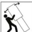
Top Heavy Risk of

Risk of Fire

Moving Parts

Risk of Hot Parts

Risk of Explosion

Risk of Fumes
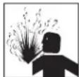
Risk of Pressure

Risk of Shock
California Proposition 65
WARNING

This product can expose you to chemicals including lead, which are known to the State of California to cause cancer and birth defects or other reproductive harm. For more information go to www.P65Warnings.ca.gov.
WARNING

You can create dust when you cut, sand, drill or grind materials such as wood, paint, metal, concrete, cement, or other masonry. This dust often contains chemicals known to cause cancer, birth defects, or other reproductive harm. Wear protective gear.
Illinois Lead Poisoning Prevention Act
WARNING

CONTAINS LEAD. MAY BE HARMFUL IF EATEN OR CHEWED. COMPLIES WITH FEDERAL STANDARDS.
Important Safety Information
Please read and save these instructions. Read carefully before attempting to assemble, install, operate or maintain the product described. Protect yourself and others by observing all safety information. Failure to comply with instructions could result in personal injury and/or property damage! Retain instructions for future reference.
This manual contains important safety, operational and maintenance information. If you have any questions, please visit www.campbellhausfeld.com for customer assistance.
⚠️ DANGER BREATHABLE AIR WARNING
This compressor/pump is not equipped and should not be used "as is" to supply breathing quality air. For any application of air for human consumption, the air compressor/pump will need to be fitted with suitable in-line safety and alarm equipment. This additional equipment is necessary to properly filter and purify the air to meet minimal specifications for Grade D breathing as described in Compressed Gas Association Commodity Specification G 7.1, OSHA 29 CFR 1910. 134, and/or Canadian Standards Associations (CSA).
DISCLAIMER OF WARRANTIES
In the event the compressor is used for the purpose of breathing air application and proper in-line safety and alarm equipment is not simultaneously used, existing warranties shall be voided, and the manufacturer disclaims any liability whatsoever for any loss, personal injury or damage.

General Safety
Since the air compressor and other components (material pump, spray guns, filters, lubricators, hoses, etc.) used make up a high pressure pumping system, the following safety precautions must be observed at all times:
- Read all manuals included with this product carefully. Be thoroughly familiar with the controls and the proper use of the equipment.
- Follow all local electrical and safety codes as well as the United States National Electrical Codes (NEC) and Occupational Safety and Health Act (OSHA).
- Only persons well acquainted with these rules of safe operation should be allowed to use the compressor.
- Keep visitors away and NEVER allow children in the work area.
- Wear safety glasses and use hearing protection when operating the unit.
- Do not stand on or use the unit as a handhold.
- Before each use, inspect compressed air system and electrical components for signs of damage, deterioration, weakness or leakage. Repair or replace defective items before using.
- Check all fasteners at frequent intervals for proper tightness.
- Do not wear loose clothing or jewelry that will get caught in the moving parts of the unit.
- Keep fingers away from a running compressor; fast moving and hot parts will cause injury and/or burns.
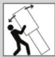
WARNING
This compressor is extremely top heavy. Use care when moving the unit around and make sure the unit is placed on flat surface when operating.
WARNING
Never install a shut-off valve between the compressor pump and the tank.

WARNING
Motors, electrical equipment and controls can cause electrical arcs that will ignite a flammable gas or vapor. Never operate or repair in or near a flammable gas or vapor. Never store flammable liquids or gases in the vicinity of the compressor.

WARNING
Never operate compressor without a beltguard. This unit can start automatically without warning. Personal injury or property damage could occur from contact with moving parts.

CAUTION
Compressor parts may be hot even if the unit is stopped.
GENERAL SAFETY INSTRUCTIONS (CONTINUED)
- If the equipment should start to vibrate abnormally, STOP the engine/motor and check immediately for the cause. Vibration is generally an indication of trouble.
- To reduce fire hazard, keep engine/motor exterior free of oil, solvent, or excessive grease.
- Never attempt to adjust ASME safety valve. Keep safety valve free from paint and other accumulations.
WARNING
An ASME code safety relief valve with a setting no higher than 200 PSI MUST be installed in the tank for this compressor. The ASME safety valve must have sufficient flow and pressure ratings to protect the pressurized components from bursting.
CAUTION
See compressor specifications for maximum operating pressure. Do not operate with pressure switch or pilot valves set higher than the maximum operating pressure.
WARNING
Maximum operating pressure is 175 PSI for single stage compressors. Do not operate with pressure switch or pilot valves set higher than 175 PSI (2-stage).
WARNING
Never use plastic (PVC) pipe for compressed air. Serious injury or death could result.
WARNING
Never attempt to repair or modify a tank! Welding, drilling or any other modification will weaken the tank resulting in damage from rupture or explosion. Always replace worn, cracked or damaged tanks.
NOTICE
Drain liquid from tank daily.
- Tanks rust from moisture build-up, which weakens the tank. Make sure to drain tank regularly and inspect periodically for unsafe conditions such as rust formation and corrosion.
- Fast moving air will stir up dust and debris which may be harmful. Release air slowly when draining moisture or depressurizing the compressor system.
Spraying Precautions

WARNING
Do not spray flammable materials in vicinity of open flame or near ignition sources including the compressor unit.

- Do not smoke when spraying paint, insecticides, or other flammable substances.
- Use a face mask/respirator when spraying and spray in a well ventilated area to prevent health and fire hazards.
- Do not direct paint or other sprayed material at the compressor. Locate compressor as far away from the spraying area as possible to minimize overspray accumulation on the compressor.
- When spraying or cleaning with solvents or toxic chemicals, follow the instructions provided by the chemical manufacturer.
The DANGER, WARNING, CAUTION, and NOTICE notifications and instructions in this manual cannot cover all possible conditions and situations that may occur. It must be understood by the operator that caution is a factor which cannot be built into this product, but must be supplied by the operator.
SAVE THESE INSTRUCTIONS DO NOT DISCARD
SPECIFICATIONS
| CE5003 XC802100 | ||
| HP (Horsepower) 5 5 | ||
| Number of Cylinders 4 4 | ||
| Number of Stages 2 2 | ||
| Air Delivery @ 90 PSI 11.9 SCFM 11.9 SCFM | ||
| Voltage 230 Volts / | 22 Amps | 230 Volts /22 Amps |
| Max Pressure 175 PSI 175 PSI | ||
| Oil Capacity | 52 ounces | 52 ounces |
| Tank Outlet Size | 3/4 NPT | 3/4 NPT |
| Weight | 410 lbs. | 410 lbs. |
DIMENSIONS
| CE5003 | XC802100 | |
| Length | 26.4 inches | 26.4 inches |
| Width | 27.97 inches | 27.97 inches |
| Height | 69.6 inches | 69.6 inches |
BEFORE YOU BEGIN
text_image
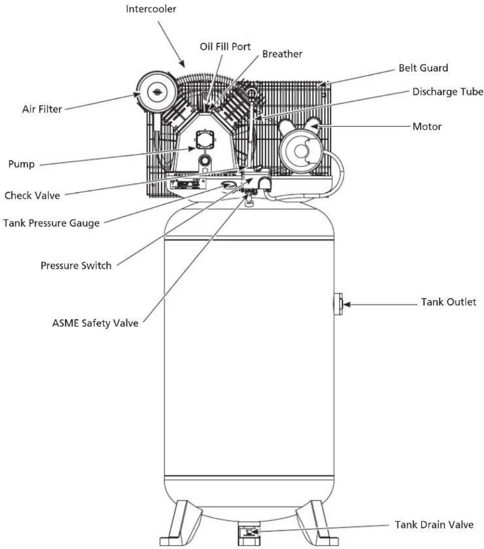
Intercooler Oil Fill Port Breather Belt Guard Discharge Tube Air Filter Motor Pump Check Valve Tank Pressure Gauge Pressure Switch ASME Safety Valve Tank Outlet Tank Drain ValveFigure 1 - Unit Identification
GETTING TO KNOW YOUR UNIT
Pressure Switch - Auto/Off Switch - In the auto position, the compressor shuts off automatically when tank pressure reaches the maximum preset pressure. After air is used from the tank and drops to a preset low level, the pressure switch automatically turns the motor back on. In the off position, the compressor will not operate. This switch should be in the off position when connecting or disconnecting the power from the unit.
When the pressure switch turns the motor off you will hear air leaking out of the pressure switch unloader valve for a short time. This releases the air pressure from the discharge tube and allows the compressor to restart easier.
ASME Safety Valve - This valve automatically releases air if the tank pressure exceeds the preset maximum.
Discharge Tube - This tube carries compressed air from the pump to the check valve. This tube becomes very hot during use. To avoid the risk of severe burns, never touch the discharge tube.
Check Valve - One-way valve that allows air to enter the tank, but prevents air in the tank from flowing back into the compressor pump.
Belt Guard - Covers the belt, motor pulley and flywheel.
Tank Drain Valve - This valve is located on the bottom of the tank. Use this valve to drain moisture from the tank daily to reduce the risk of corrosion.
Tank Pressure Gauge - Indicates amount of air pressure stored in tank.
Hose Pressure Gauge - Indicates amount of air pressure in hose used to operate tools. This pressure is increased or decreased by the regulator.
Regulator - The regulator controls the amount of air pressure released at the hose outlet.
Air Filter - Keeps large particulates out of the air flowing into the compressor.
Breather - Vent for crankcase.
Oil Fill Port - Port used to refill the oil in the pump after oil changes or when oil is low.
Pump - Cast Iron 2-Stage air compressor pump that generates compressed air.
Motor - Power source that drives the pump to create compressed air.
INSTALLATION INSTRUCTIONS
WARNING
Disconnect, tag and lock out power source then release all pressure from the system before attempting to install, service, relocate or perform any maintenance.
CAUTION
Do not lift or move unit without appropriately rated equipment. Be sure the unit is securely attached to lifting device used. Do not lift unit by holding onto tubes or coolers. Do not use unit to lift other attached equipment.
CAUTION
Never use the wood shipping skids for mounting the compressor.
NOTICE
This compressor is not intended for outdoor installation.
Preparation
Before beginning installation and/or assembly of product, make sure all parts are present. Compare parts with package contents list. If any part is missing or damaged, do not attempt to assemble or use the product.
WARNING
Do not operate unit if damaged during shipping, handling or use. Damage may result in bursting and cause injury or property damage.
Estimated Installation and Assembly Time: 120 minutes
Tools Required for Installation and Assembly (not included): Safety Glasses; Work gloves; 9/16 in.
Socket and Ratchet; Tape measure; Hammer drill and Masonry bit; Hammer; Phillips screwdriver; Flathead screwdriver; Pipe wrench; Two adjustable wrenches; 1/4 in. Nut driver, Socket or Wrench; 240 Volt, 30 Amp double pole circuit breaker; Voltage meter; Vibration pads; 3/8 in. x 5 in. Wedge anchors (for concrete installation)
INSTALLATION INSTRUCTIONS (CONTINUED)
Picking the Location
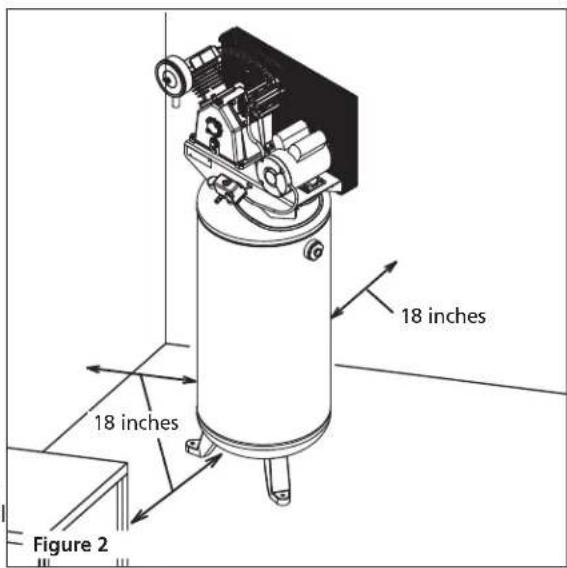
Install and operate unit at least 18 inches from any obstructions in a clean, well ventilated area. The surrounding air temperature should not exceed 100^ F. This will ensure an unobstructed flow of air to cool compressor and allow adequate space for maintenance.
CAUTION
Do not locate the compressor air inlet near steam, paint spray, sandblast areas or any other source of contamination.
NOTE: If compressor operates in a hot, moist environment, supply compressor pump with clean, dry outside air. Supply air should be piped in from external sources.
Tank Mounting
The tank should be bolted into a flat, even, concrete floor or on a separate concrete foundation. Vibration isolators should be used between the tank leg and the floor. Model MP345700AJ isolator pads are recommended for installation.
When using isolator pads, do not draw bolts tight. Allow the pads to absorb vibrations. When isolators are used, a flexible hose or coupling should be installed between the tank and service piping.
CAUTION
Failure to properly install the tank can lead to cracks at the welded joints and possible bursting.
-
Unbolt the unit from the shipping skid. Use a ratchet with a 9/16 in. socket. Remove the unit from the skid. This requires at least two people - one person to walk the unit off the skid and one to help maintain balance so the unit does not topple. Place the unit where you plan to install it (at least 18 in. from any wall or surface).
-
Place pre-drilled vibration pads (sold separately) under each foot to avoid unnecessary vibration which could damage the unit.
Using the mounting holes and the holes of the vibration pads as a guide, drill holes into concrete using a 3/8 in. masonry bit. Holes drilled must be at least 5 in. into the concrete.
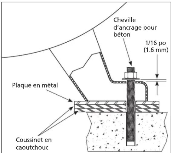
- Insert mounting bolts. Use 3/8 in. x 5 in. wedge anchors (not included) to secure the unit. Place nut and washer on bolt. Thread nut onto bolt until tops are flush. Strike bolt with hammer until nut and washer are setting on top of the compressor foot.
Tighten nut using ratchet with a 9/16 in. socket until anchor is set (using installation torque specifications of bolt being used). Loosen nut to leave a 1/16 in. (1.6 mm) gap for stress relief during unit operation.
text_image
18 inches 18 inches Figure 2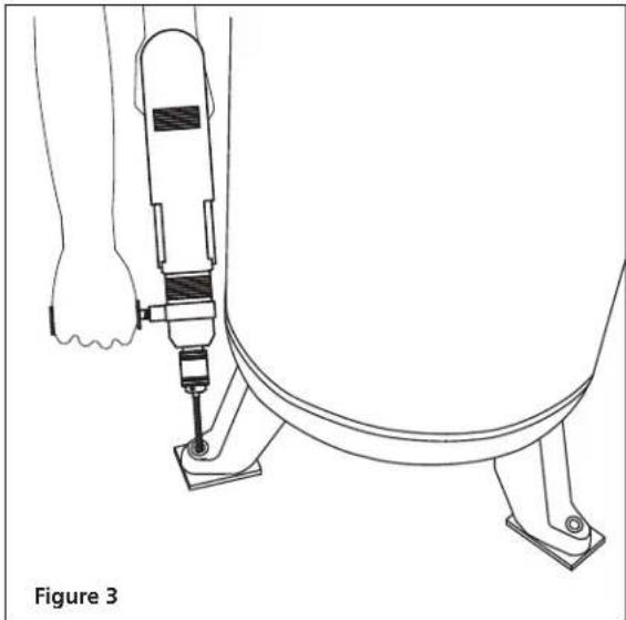
natural_image
Line drawing of a hand using a drill bit to lift a circular component, labeled 'Figure 3' (no text or symbols on the diagram itself)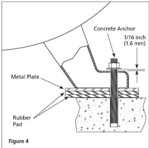
text_image
Concrete Anchor 1/16 inch (1.6 mm) Metal Plate Rubber Pad Figure 4Piping
WARNING
Never use plastic (PVC) pipe for compressed air. Serious injury or death could result.
Any tube, pipe or hose connected to the unit must be able to withstand the temperature generated and retain the pressure. All pressurized components of the air system must have a pressure rating of 200 PSI or higher. Minimum recommended pipe size is 3/4 in. Larger diameter pipe is always better. Incorrect selection and installation of any tube, pipe or hose could result in bursting and injury. Connect piping system to tank using the same size fitting as the discharge port.
Minimum Pipe Size For Compressed Air Line
| SCFM | LENGTH OF PIPING SYSTEM | |
| 25 FEET 50 FEET 100 FEET 250 FEET | ||
| 10 1/2 inch | 1/2 inch 3/4 inch 3/4 inch | |
| 20 3/4 inch | 3/4 inch 3/4 inch 1 inch | |
| 40 3/4 inch | 1 inch 1 inch 1 inch | |
| 60 3/4 inch | 1 inch 1 inch 1 inch | |
| 100 1 inch | 1 inch 1 inch | 1-1/4 inch |
Chart 1
Installing A Shut-Off Valve
natural_image
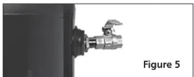
Close-up of a mechanical component with a metallic valve and handle, labeled as Figure 5 (no text or symbols on the device itself)A shut-off valve should be installed on the discharge port of the tank to control the air flow out of the tank. The valve should be located between the tank and the piping system.
WARNING
Never install a shut-off valve between the compressor pump and the tank. Personal injury and/or equipment damage may occur. Never use reducers in discharge piping.
When creating a permanently installed system to distribute compressed air, find the total length of the system and select pipe size from Chart 1. Bury underground lines below the frost line and avoid pockets where condensation can gather and freeze.
Apply air pressure to the piping installation and make sure all joints are free from leaks BEFORE underground lines are covered. Before putting the compressor into service, find and repair all leaks in the piping, fittings and connections.
INSTALLATION INSTRUCTIONS (CONTINUED)
Wiring
DANGER
Improperly grounded motors are shock hazards. Make sure all the equipment is properly grounded.
WARNING
All wiring and electrical connections must be performed by a qualified electrician familiar with induction motor controls. Installations must be in accordance with local and national codes.
WARNING
Overheating, short circuiting and fire damage will result from inadequate wiring.
WARNING
Disconnect, tag and lock out power source, then release all pressure from the system before attempting to install, service, relocate or perform any maintenance.
NOTICE
Damage to the motor from improper electrical voltage or connection will void the warranty.
Wiring must be installed in accordance with National Electrical Code and local codes and standards that have been set up covering electrical apparatus and wiring. These should be consulted and local ordinances observed. Be certain that adequate wire sizes are used, and that:
• Service is of adequate ampere rating.
- The supply line has the same electrical characteristics (voltage, cycles and phase) as the motor. Refer to motor name plate for electrical ratings and specifications.
- The line wire is the proper size and that no other equipment is operated from the same line. The chart gives minimum recommended wire sizes for compressor installations.
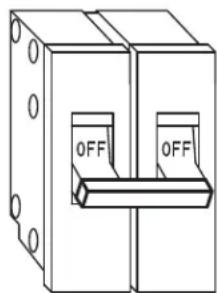
- Use a slow blow fuse type T or a 240 Volt double pole circuit breaker.
natural_image
Technical line drawing of a mechanical switch or bracket with two labeled buttons (no text or symbols beyond 'OFF' labels)Figure 6
Minimum Wire Size (Use 75°C Copper Wire)
Make sure voltage is correct with the motor wiring.
NOTE: If using 208 volts single phase, make sure the motor name plate states it is rated for 208 volts single phase. 230 volt single phase motors do not work on 208 volts unless they have the 208 volt rating.
HP Amps
5.08 AWG
Single Phase
230V
Recommended wire sizes may be larger than the minimum set up by local ordinances. If so, the larger size wire should be used to prevent excessive line voltage drop. The additional wire cost is very small compared with the cost of repairing or replacing a motor electrically "starved" by the use of supply wires which are too small.
WIRING INSTRUCTIONS
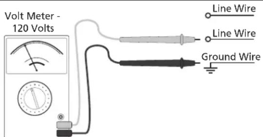
- Inspect the source wiring before continuing with installation. Confirm voltage with volt meter line-to-ground (see Figure 7).
Volt meter should read 120 Volts.
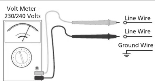
Confirm voltage with volt meter line-to-line Volt meter should read 230 / 240 Volts (see Figure 8).
text_image
Volt Meter - 120 Volts Line Wire Line Wire Ground WireFigure 7 Figure 8
text_image
Volt Meter - 230/240 Volts Line Wire Line Wire Ground Wire-
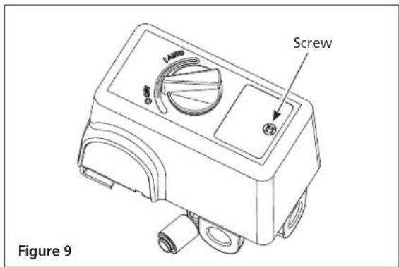
Remove the pressure switch cover by loosening the screw (see Figure 9). Use a Phillips screwdriver (not included). Pressure switch styles may vary.
-
Familiarize yourself with the pressure switch once cover is removed.
-
Remove ground screw. Install strain relief on pressure switch. DO NOT tighten strain relief on power cord until wiring is complete. Insert the bare wires (black, white, bare/green) through the strain relief.
Attach bare/green ground wire first to ground screw on pressure switch body.
Look for the "Line" markings on pressure switch. Install Line wires and tighten terminal screws.
- Tighten strain relief nut. Place a flathead screwdriver (not included) into raised notch and tap screwdriver with hammer (not included) until tight.
Tighten strain relief screws to hold power cord securely. Replace the pressure switch cover (knob must be in the same position as when removed to sit correctly in place). Tighten the pressure switch screw with Phillips screwdriver. Check that switch is in the OFF position. Follow break-in procedure starting on page 13.
text_image
LAMP Screw Figure 9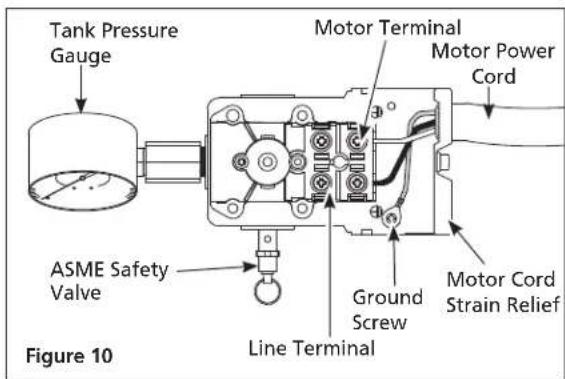
text_image
Tank Pressure Gauge ASME Safety Valve Figure 10 Motor Terminal Motor Power Cord Ground Screw Motor Cord Strain Relief Line Terminal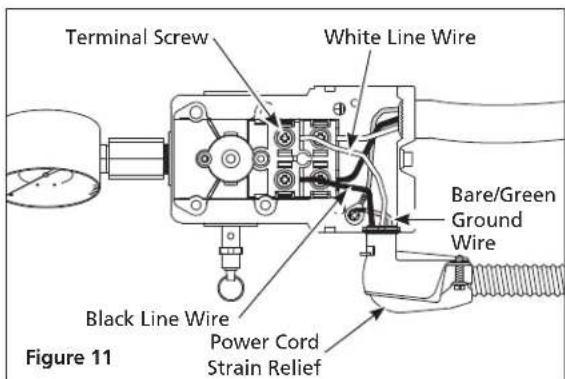
text_image
Terminal Screw White Line Wire Bare/Green Ground Wire Black Line Wire Power Cord Strain Relief Figure 11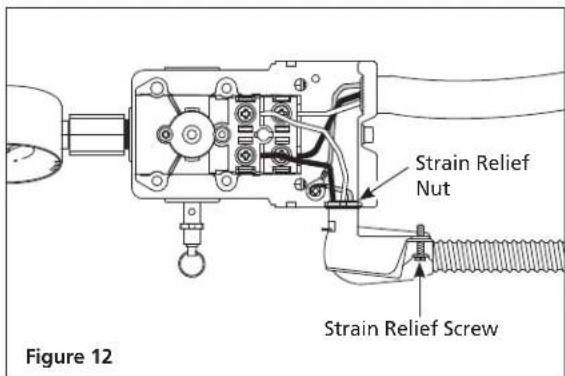
text_image
Strain Relief Nut Strain Relief Screw Figure 12INSTALLATION INSTRUCTIONS (CONTINUED)
Grounding

WARNING
Improperly grounded electrical components are shock hazards. Make sure all the components are properly grounded to prevent death or serious injury.
This product must be grounded. Grounding reduces the risk of electrical shock by providing an escape wire
for the electric current if short circuit occurs. This product must be installed and operated with a power cord or cable that has a grounding wire.
Install permanent wiring from the electrical source to the pressure switch with a ground conductor connected to the grounding screw on the pressure switch. A properly sized cord with a ground conductor and plug may also be installed by the user.
Installing Air Filter
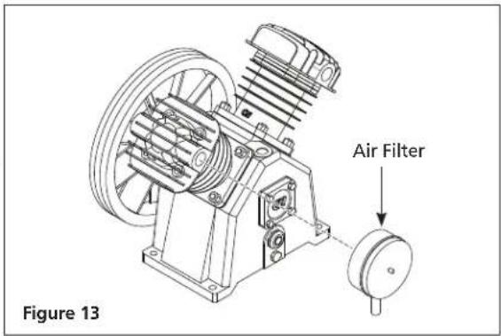
Install air filter on pump (see Figure 13). Filter styles may vary.
Lubrication
CAUTION
This unit contains no oil. Before operating compressor, fill to the center of the sight gauge (see Figure 15).
CAUTION
Using any other type of oil may shorten pump life and damage valves.
Recommended Oil (2 Options)
Single viscosity SAE 30 ISO100 nondetergent compressor oil. Part number ST125303AV (0.5 qt) or ST126701AV (4 qt).
10W30 synthetic oil such as Mobil 1 ^® or CE0032 (1 qt).
Oil Capacity
Approximately 52 oz.
Remove oil fill plug on pump. Check oil level; some models are shipped with oil in the pump. Add oil if needed. Fill the pump with oil to the center of the sight gauge using oil fill opening (see Figure 15). Place oil fill plug back on pump. Do NOT fill the pump through the breather cap opening as this may cause oil to leak and spray out during operation.
Do not use regular automotive oil. Additives in regular motor oil can cause valve deposits and reduce pump life.
For maximum pump life, drain and replace oil after the first 50 hours of run time and then follow the regular maintenance schedule outlined later in the manual.
This pump has an oil sight glass as shown in Figure 14. Oil level can be monitored and maintained as shown in Figure 15.
text_image
Air Filter Figure 13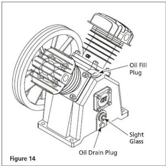
text_image
Oil Fill Plug Sight Glass Oil Drain Plug Figure 14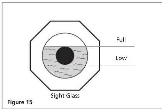
text_image
Full Low Sight Glass Figure 15NOTE: Some residual oil may still be in the pump from factory testing leaving a thin coat on the sight gauge; however, there is not enough oil to operate the unit.
OPERATING INSTRUCTIONS
Start-up/Break-in Procedure
WARNING
Do not attach air tools to open end of the hose until start-up is completed and the unit checks okay.
WARNING
Never disconnect threaded joints with pressure in tank!
- Return power to unit from main.
- Check oil level per the Lubrication Section of this manual.
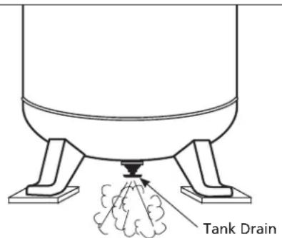
- Open the tank drain valve (see Figure 16). Turn outlet valve to open air flow.
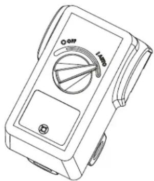
- Move pressure switch to the AUTO position to run the unit (see Figure 17).
- Run the unit for thirty (30) minutes at zero (0) PSI (under no load) to break in pump parts.
- Move the pressure switch lever or knob to OFF and turn tank drain valve to shut off air flow. The compressor is now ready for use.
- Change oil after first fifty (50) hours of operation. Perform oil changes every three (3) months or two hundred (200) hours of run time, whichever comes first.
text_image
Tank DrainFigure 16 Figure 17
natural_image
Line drawing of a handheld digital multimeter with rotary dial and handle (no text or symbols)On/Off Cycling of Compressor
WARNING
Drain tank every day to prevent corrosion and possible injury due to tank damage. For optimal performance of tank drain, tank pressure should be between 10 PSI - 40 PSI. Do not operate drain with more than 40 PSI in tank or drain valve may be damaged. Drain tank of moisture daily using the drain valve in the bottom of the tank.
NOTICE
Drain liquid from tank daily.
In the AUTO position, the compressor pumps air into the tank. When a shut-off (preset "cut-out") pressure is reached, the compressor automatically shuts off.
If the compressor is left in the AUTO position and air is depleted from the tank by use of a tire chuck, tool, etc., the compressor will restart automatically at its preset "cut-in" pressure. When a tool is being used continuously, the compressor will cycle on and off automatically.
In the OFF position, the compressor will not operate.
MOISTURE IN COMPRESSED AIR
Moisture in compressed air will form into droplets as it comes from an air compressor pump. When humidity is high or when a compressor is in continuous use for an extended period of time, this moisture will collect in the tank. When using a paint spray or sandblast gun, this water will be carried from the tank through the hose, and out of the gun as droplets mixed with the spray material.
IMPORTANT: This condensation will cause water spots in a paint job, especially when spraying other than water based paints. If sandblasting, it will cause the sand to cake and clog the gun, rendering it ineffective. A filter in the air line, located as near to the gun as possible, will help eliminate this moisture.
TROUBLESHOOTING GUIDE
SYMPTOM POSSIBLE CAUSE(S) CORRECTIVE ACTION
| Low discharge pressure 1. Air demand exceeds pump capacity 1. Reduce air demand or use a compressor with more capacity. | ||
| 2. Air leaks (fittings, tubing on compressor, or plumbing outside of system). | 2. Listen for escaping air. Apply soap solution to all fittings and connections. Bubbles will appear at points of leakage. Tighten or replace leaking fittings or connections. Use pipe thread sealant. | |
| 3. Restricted air intake 3. Clean or replace the air filter element. | ||
| 4. Blown gaskets 4. Replace any gaskets proven faulty on inspection. | ||
| 5. Leaking or damaged valves 5. Remove head and inspect for valve breakage, misaligned valves, damaged valve seats, etc. Replace defective parts and reassemble. | ||
| gasket each time the head is removed. | ||
| Excessive noise (knocking) | 1. Loose motor pulley or flywheel. | 1. Tighten pulley / flywheel clamp bolts and set-screws. |
| 2. Loose fasteners on pump or motor. | 2. Tighten fasteners. | |
| 3. Lack of oil in crankcase | 3. Check for proper oil level; if low, check for possible damage to bearings. Dirty oil can cause excessive wear. | |
| 4. Worn connecting rod | 4. Replace connecting rod. Maintain oil level and change oil more frequently. | |
| 5. Worn piston pin bores | 5. Remove piston assemblies from the compressor and inspect for excess wear. Replace excessively worn piston pin or pistons, as required. Maintain oil level and change oil more frequently. | |
| 6. Piston hitting the valve plate | 6. Remove the compressor head and valve plate and inspect for carbon deposits or other foreign matter on top of piston. Replace head and valve plate using new gasket. See Lubrication section for recommended oil. | |
| 7. Noisy check valve in compressor system | 7. Replace check valve. check valve with air pressure in tank. | |
| Large quantity of oil in the discharge airNOTE: In an oil lubricated compressor there will always be a small amount of oil in the air stream. | 1. Worn piston rings | 1. Replace with new rings. Maintain oil level and change oil more frequently. |
| 2. Compressor air intake restricted | 2. Clean or replace filter. Check for other restrictions in the intake system. | |
| 3. Excessive oil in compressor | 3. Drain down to full level. | |
| 4. Wrong oil viscosity | 4. Use Mobil 1® 10W-30 or full synthetic. | |
| Water in discharge air/tank | Normal operation. The amount of water increases with humid weather | 1. Drain tank more often. At least daily.2. Add a filter to reduce the amount of water in the air line. |
SYMPTOM POSSIBLE CAUSE(S) CORRECTIVE ACTION
| Motor hums and runs slowly or not at all. | 1. Low voltage. 1. Check incoming voltage. It should be approximately230 volts. Motor will not run properly on 208 volts.Low voltage could be due to wires (from electrical source to compressor) being too small in diameter and / or too long. Have a qualified electrician check these conditions and make repairs as needed. | |
| 2. Too many devices on same circuit. 2. Limit the circuit to the use of compressor only. | ||
| 3. Loose electrical connections. 3. Check all electrical connections. | ||
| 4. Malfunctioning pressure switch - contacts will not close. | 4. Replace pressure switch. | |
| 5. Malfunctioning check valve. 5. Replace check valve. | ||
| check valvewith air pressure in tank. | ||
| 6. Defective unloader valve on pressure switch. | 6. Replace unloader valve. | |
| 7. Defective motor capacitor(s). 7. Replace capacitor(s). | ||
| 8. Defective motor. 8. Replace motor. | ||
| Reset mechanism cuts out repeatedly or circuit breaker trips repeatedly. | 1. Lack of proper ventilation / room temperature too high. | 1. Move compressor to well-ventilated area. |
| 2. Too many devices on same circuit. 2. Limit the circuit to the use of only the air compressor. | ||
| 3. Restricted air intake. | 3. Clean or replace filter element. | |
| 4. Loose electrical connection. | 4. Check all electrical connections. | |
| 5. Pressure switch shut-off pressure set too high. | 5. Replace pressure switch. | |
| 6. Malfunctioning check valve. 6. Replace check valve. | ||
| check valvewith air pressure in tank. | ||
| 7. Defective unloader valve on pressure switch. | 7. Replace unloader valve. | |
| 8. Defective motor capacitor(s). 8. Replace capacitor(s). | ||
| 9. Malfunctioning motor. | 9. Replace motor. | |
| Tank does not hold pressure when compressor is off and the shut off valve is closed. | 1. Air leaks (fittings, tubing on compressor, or plumbing outside system). | 1. Check all connections with soap and water solution.Tighten; or remove and apply sealant to threads, then reassemble. |
| 2. Worn check valve. | 2. Replace check valve. | |
| check valvewith air pressure in tank. | ||
| 3. Check tank for cracks or pin holes. | 3. Replace tank. Never repair a damaged tank. | |
| Pressure switch continuously blows air out the unloader valve | Malfunctioning check valve | Replace the check valve if the unloader valve on the pressure switch bleeds off constantly when unit shuts off. |
| check valvewith air pressure in tank. | ||
| Pressure switch does not release air when the unit shuts off | Malfunctioning unloader valve on pressure switch | Replace the pressure switch if it does not release the pressure for a short period of time when the unit shuts off. |
| pressureswitch with air pressure in tank | ||
| Excessive vibration | 1. Loose fasteners on pump or motor | 1. Tighten fasteners. |
| 2. Belt needs replaced | 2. Replace with correct size. | |
| 3. Belt alignment | 3. Align flywheel and pulley. | |
MAINTENANCE AND INSPECTION INSTRUCTIONS
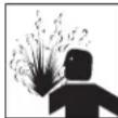
WARNING
Disconnect, tag and lock out power source then release all pressure from the system before attempting to install, service, relocate or perform any maintenance.
All repairs should be performed by an authorized service representative.
Disconnect power cord plug from power source receptacle. Clean debris from motor, flywheel, tank, air lines and pump cooling fins.
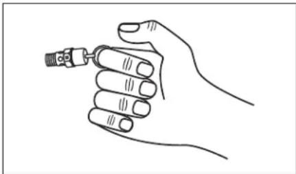
In order to maintain efficient operation of the compressor system, check the air filter and oil level before each use. The ASME safety valve should also be checked daily (see Figure 13). Pull ring on safety valve and allow the ring to snap back to normal position. This valve automatically releases air if the tank pressure exceeds the preset maximum. If air leaks after the ring has been released, or the valve is stuck and cannot be actuated by the ring, the ASME safety valve must be replaced.
natural_image
Line drawing of a hand holding a small mechanical component (no text or symbols)Figure 13 - ASME Safety Valve
WARNING
Do not tamper with the ASME safety valve.
Tank
WARNING
Never attempt to repair or modify a tank! Welding, drilling or any other modification will weaken the tank resulting in damage from rupture or explosion. Always replace worn, cracked or damaged tanks.
NOTICE
Drain liquid from tank daily.
Drain Tank: Disconnect, tag and lock out power source; release pressure. Drain moisture from tank by opening drain valve underneath tank once tank pressure is less than 40 PSI (See Figure 11 on page 12).
The tank should be carefully inspected at a minimum of once a year. Look for cracks forming near the welds. If a crack is detected, remove pressure from tank immediately and replace.
Compressor Lubrication
See Installation. Add oil as required. The oil should be changed every three months or after every 200 hours of operation; whichever comes first.
If the compressor is run under humid conditions for short periods of time, the humidity will condense in the crankcase and cause the oil to look creamy. Oil contaminated by condensed water will not provide adequate lubrication and must be changed immediately. Using contaminated oil will damage bearings, pistons, cylinders and rings and is not covered under warranty. To avoid water condensation in the oil, periodically run the compressor with tank pressure near 120 PSI for 2-stage compressors by opening the drain cock or an air valve connected to the tank or hose. Run the pump for an hour at a time at least once a week or more often if the condensation reoccurs.
IMPORTANT: Change oil after first 50 hours of operation.
Air Filter
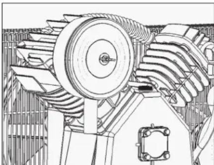
Never run the compressor pump without an intake air filter or with a clogged intake air filter. The air filter element should be checked monthly (see Figure 14). Operating compressor with a dirty filter can cause high oil consumption and increase oil contamination in the discharge air. If the air filter is dirty it must be replaced.
natural_image
Technical line drawing of a mechanical assembly with gears and shafts (no text or symbols)Figure 14
Belts
WARNING
Lock out and tag the power then release all pressure from the tank to prevent unexpected movement of the unit.
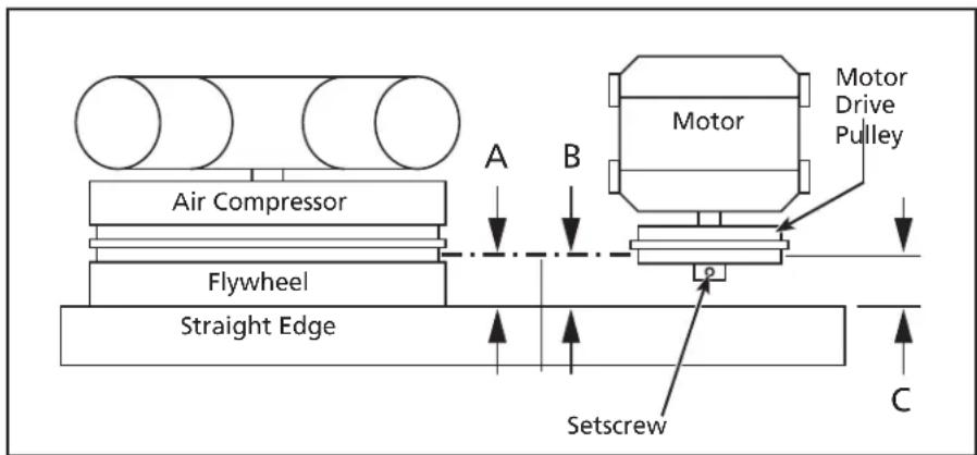
Check belt tension every 3 months. Adjust belt tension to allow 3/8 inch to 1/2 inch deflection with normal thumb pressure. Also, align belts using a straight edge against the face of the flywheel and touching the rim on both sides of the face. The belts should be parallel to this straight edge (see Figure 15). Dimension A should be the same as B and C to ensure proper alignment of the belts.
Slots in the bed-plate allow for sliding the motor back and forth to adjust belt tension.
text_image
Air Compressor Flywheel Straight Edge A B Motor Motor Drive Pulley Setscrew CFigure 15 - Top View
Removing Belt Guard
WARNING
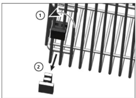
When removing belt guard front to inspect or replace belts, inspect plastic retaining clips and replace if damaged or if clip can be removed without a tool.
Removing Retaining Clips
- Using crescent wrench on pliers, rotate clip 90°.
- Pull clip out and away from beltguard.
- Reverse process to reinstall after inspecting the clip.
text_image
Diagram showing a mechanical assembly with labeled components and directional arrows, likely illustrating a process or assembly.Figure 16
Storage
If compressor is to be stored for a short period of time, make sure that it is stored in a normal position and in a cool protected area.
| MAINTENANCE SCHEDULE | |
| OPERATION DAILY WEEKLY MONTHLY 3 MONTHS | |
| Check Oil Level | ● |
| Drain Tank | ● |
| Check Air Filter | ● |
| Check Safety Valve | ● |
| Clean Unit | ● |
| Check Belt Tightness | ● |
| Change Oil* | ● |
* Change oil after first fifty (50) hours of operation then perform oil changes every three (3) months or two hundred (200) hours of run time, whichever comes first.
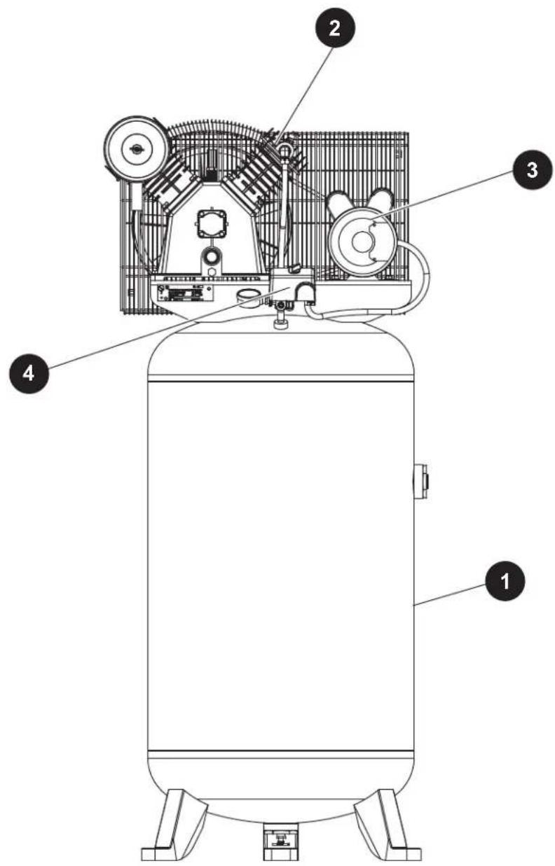
REPAIR PARTS ILLUSTRATION FOR CE5003 AND XC802100
text_image
Technical diagram of a vehicle interior with numbered components labeled 1, 2, and 3.For Repair Parts, visit www.campbellhausfeld.com
24 hours a day - 365 days a year
Please provide following information:
- Model number
- Serial number (if any)
- Part description and number as shown in parts list
REPAIR PARTS LIST FOR CE5003 AND XC802100
Ref.
No. Description Part Number: Qty.
| 1 | 80 Gallon Tank AR068400CG 1 |
| 2 | 5HP 2-Stage Reciprocating Pump XC002500IP 1 |
| 3 | 3.5HP Electric Motor MC019700IP 1 |
| 4 | Pressure Switch CW220000AV 1 |
UNIT SERVICE PARTS
| tion Part Number: Qty. | ||
| Drain Valve | SR060513SV | 1 |
| Motor Pulley | PU017300AV | 1 |
| Vee Belt | BT021501AV | 1 |
| Check Valve/Exhaust Tube Kit | XC001900SV | 1 |
| Pressure Switch Kit | MY001000SV | 1 |
| Belt Guard Kit | BG900100SV | 1 |
| Intercooler Kit | XC002700AV | 1 |
PUMP SERVICE PARTS
| tion Part Number: Qty. | ||
| Valve Replacement Kit | XC001000AV | 1 |
| Ring Replacement Kit | XC001100AV | 1 |
| Gasket Kit | XC001300AV | 1 |
| Flywheel | XC001400AV | 1 |
| Pump Accessories | XC001500AV | 1 |
| Air Filter Element | XC001700AV | 1 |
Reminder: Keep your dated proof of purchase for warranty purposes! Attach it to this manual or file it for safekeeping.
LIMITED WARRANTY
- DURATION: From the date of purchase by the original purchaser as follows: Three Years.
- WHO GIVES THIS WARRANTY: Campbell Hausfeld, MAT Industries, LLC., Long Grove, IL 60047.
Visit www.campbellhausfeld.com.
-
WHO RECEIVES THIS WARRANTY (PURCHASER): The original purchaser (other than for purposes of resale) of the compressor.
-
WHAT PRODUCTS ARE COVERED BY THIS WARRANTY: This air compressor.
- WHAT IS COVERED UNDER THIS WARRANTY: Parts and Labor to remedy substantial defects due to material and workmanship during the first year of ownership with the exceptions noted below. Parts only to remedy substantial defects due to material and workmanship during remaining term of coverage with exceptions noted below.
- WHAT IS NOT COVERED UNDER THIS WARRANTY:
A. Implied warranties, including those of merchantability and FITNESS FOR A PARTICULAR PURPOSE ARE LIMITED FROM THE DATE OF ORIGINAL PURCHASE AS STATED IN THE DURATION. Some States do not allow limitations on how long an implied warranty lasts, so the above limitations may not apply to you
B. ANY INCIDENTAL, INDIRECT, OR CONSEQUENTIAL LOSS, DAMAGE, OR EXPENSE THAT MAY RESULT FROM ANY DEFECT, FAILURE, OR MALFUNCTION OF THE CAMPBELL HAUSFELD PRODUCT. Some States do not allow the exclusion or limitations of incidental or consequential damages, so the above limitation or exclusion may not apply to you.
C. Any failure that results from an accident, purchaser's abuse, neglect or failure to operate products in accordance with instructions provided in the owner's manual(s) supplied with compressor.
D. Pre-delivery service, e.g. assembly, oil or lubricants, and adjustment.
E. Items or service that is normally required to maintain the product, i.e. lubricants, filters and gaskets, etc.
F. Additional items not covered under this warranty:
- Excluded items pertaining to All Compressors
a. Any component damaged in shipment or any failure caused by installing or operating unit under conditions not in accordance with installation and operation guidelines or damaged by contact with tools or surroundings.
b. Pump or valve failure caused by rain, excessive humidity, corrosive environments or other contaminants.
c. Cosmetic defects that do not interfere with compressor functionality.
d. Rusted tanks, including but not limited to rust due to improper drainage or corrosive environments.
e. The following components are considered normal wear items and are not covered after the first year of ownership. Electric motor, check valve, pressure switch, regulator, pressure gauges, hose, tubing, pipe, fittings and couplers, screws, nuts, hardware items, belts, pulleys, flywheel, air filter and housing, gaskets, seals, oil leaks, air leaks, oil consumption or usage, piston rings.
f. Tank drain valves.
g. Damage due to incorrect voltage or improper wiring.
h. Other items not listed but considered general wear parts.
i. Pressure switches, air governors, load/unload devices, throttle control devices and safety valves modified from factory settings.
j. Damage from inadequate filter maintenance.
k. Induction motors operated with electricity produced by a generator.
- Excluded items specific to Lubricated Compressors:
a. Pump wear or valve damage caused by using oil not specified.
b. Pump wear or damage caused by any oil contamination.
c. Pump wear or damage caused by failure to follow proper oil maintenance guidelines, operation below proper oil level or operation without oil.
G. Labor, service call, or transportation charges after the first year of ownership of stationary compressors. Stationary compressors are defined as not including a handle or wheels.
- RESPONSIBILITIES OF WARRANTOR UNDER THIS WARRANTY: Repair or replace, at Warrantor's option, compressor or component which is defective, has malfunctioned and/or failed to conform within the duration of the specific warranty period.
- RESPONSIBILITIES OF PURCHASER UNDER THIS WARRANTY:
A. Provide dated proof of purchase and maintenance records.
B. Visit www.campbellhausfeld.com to obtain your warranty service options. Freight costs must be borne by the purchaser.
C. Use reasonable care in the operation and maintenance of the products as described in the owner's manual(s).
D. Repairs requiring overtime, weekend rates, or anything beyond the standard manufacturer warranty repair labor reimbursement rate.
E. Time required for any security checks, safety training, or similar for service personnel to gain access to facility.
F. Location of unit must have adequate clearance for service personnel to perform repairs and be easily accessible.
- WHEN WARRANTOR WILL PERFORM REPAIR OR REPLACEMENT UNDER THIS WARRANTY: Repair or replacement will be scheduled and serviced according to the normal work flow at the servicing location, and depending on the availability of replacement parts.
This Limited Warranty applies in the U.S., Canada and Mexico only and gives you specific legal rights. You may also have other rights which vary from state to state or country to country.
CH CAMPBELL HAUSFELD®
natural_image
Technical line drawing of a cylindrical industrial machine with internal components and mounting feet (no text or symbols)CH CAMPBELL HAUSFELD.
natural_image
Line drawing of a hand using a drill pen to lift a large cylindrical object (no text or symbols present)Figure 3
natural_image
Close-up of a mechanical valve component labeled Figure 5, showing no text or symbols on the device itself.natural_image
Technical line drawing of a mechanical clamping device with two labeled buttons (0FF and 0FF), no text or symbols present.Figure 6
Recommended Oil (2 Options)
natural_image
Line drawing of a handheld electronic device with dial and buttons (no text or symbols)natural_image
Line drawing of a hand holding a small mechanical component (no text or symbols)natural_image
Technical line drawing of a mechanical assembly with gears and housing (no text or symbols)Figure 19
Courroies
AVERTISSEMENT
text_image
Diagram showing mechanical assembly with labeled parts 1 and 2, likely illustrating a gear or rack mechanism.Figure 21
Entreposage
text_image
Technical schematic diagram of a mechanical device with numbered components labeled 1, 2, 3, and 4.CH CAMPBELL HAUSFELD
natural_image
Technical line drawing of a cylindrical industrial machine with internal components and mounting feet (no text or symbols)CH CAMPBELL HAUSFELD.
This product can expose you to chemicals including lead, which are known to the State of California to cause cancer and birth defects or other reproductive harm. For more information go to www.P65Warnings.ca.gov.
ADVERTENCIA
You can create dust when you cut, sand, drill or grind materials such as wood, paint, metal, concrete, cement, or other masonry. This dust often contains chemicals known to cause cancer, birth defects, or other reproductive harm. Wear protective gear.
CONTAINS LEAD. MAY BE HARMFUL IF EATEN OR CHEWED. COMPLIES WITH FEDERAL STANDARDS.
natural_image
Line drawing of a hand using a drill bit to measure a circular object, labeled 'Figura 3' (no other text or symbols)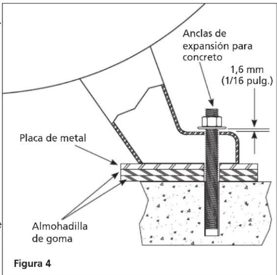
natural_image
Close-up of a metallic valve component with a label 'Figura 5' (no other text or symbols visible)natural_image
Line drawing of a digital multimeter with dial and rotary knob (no text or symbols)natural_image
Line drawing of a hand holding a small mechanical component (no text or symbols)natural_image
Technical line drawing of a mechanical assembly with gears and shafts (no text or symbols)Figura 19
Correa
ADVERTENCIA
text_image
Diagram showing mechanical assembly with labeled components and directional arrows, likely illustrating a gear or rack mechanism.Figura 21


