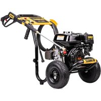
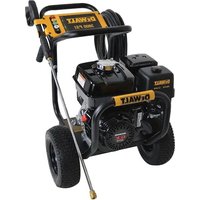
USER MANUAL DWPW61147 DEWALT
NOTE: Photographs and line drawings used in this manual are for reference only and do not represent a specific model.
WARNING: To reduce the risk of injury, read the pressure washer instruction manual and the engine instruction manual before operating pressure washer.
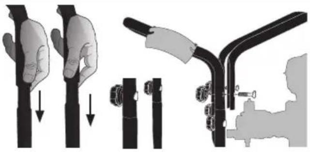
A Install the Handle
Slide the handle assembly onto the frame, align holes, insert saddle bolts and secure in place with knobs. Tighten until snug.
Align holes in the secondary handle with the mounting holes in the handle assembly. (Optional, not all models are equipped with secondary handle)
Insert saddle bolts through aligned holes and secure secondary handle to handle assembly with knobs. Tighten until snug.
natural_image
Illustration showing three-step mechanical assembly: hand holding a cylindrical component, clamping a bolt, and adjusting a curved tool (no text or symbols)
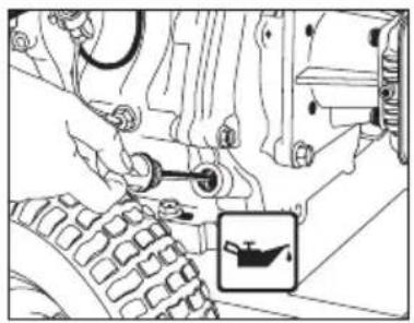
B Add/Check Oil
The engine is shipped without oil. Before starting engine, add the oil provided. Check oil level prior to each use. Refer to Engine Owner's Manual for complete procedure.
natural_image
Mechanical assembly diagram showing a gear and valve mechanism with a small inset image of a boat (no text or symbols)
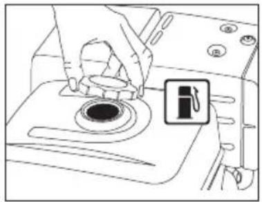
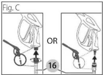
C Add Gasoline
In a well ventilated outdoor area add fresh, high quality, unleaded gasoline with a pump octane rating of 86 or higher. Do not overfill. Wipe up spilled fuel before starting the engine. Refer to Engine Owners Manual for complete procedure.
natural_image
Line drawing of hands using a tool to clean or install a circular component on a machine (no text or symbols visible)
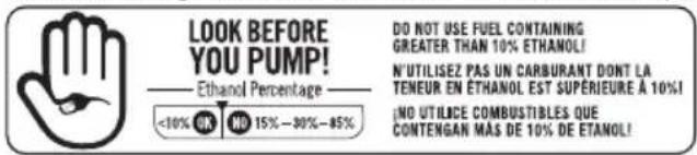
IMPORTANT: Ethanol Shield™ (sold separately) is a fuel stabilizer that helps eliminate and prevent ethanol related problems in power equipment. Follow the instructions on the container and add to the gasoline.
QUICK START GUIDE
DANGER:
Never run engine indoors or in enclosed, poorly ventilated areas. Engine exhaust contains carbon monoxide, an odorless and deadly gas.
- Risk of fluid injection and laceration. When using the high-pressure setting, DO NOT allow the high-pressure spray to come in contact with unprotected skin, eyes or with any pets or animals. Serious injury will occur.
WARNING: Do not allow the unit to run for more than two minutes without the gun trigger being pulled. This cause overheating and damage to the pump. When the temperature inside the pump rises too high, the thermal relief valve will open and release a spray of water from the pump to lower the internal temperature. The valve will then close.
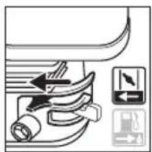
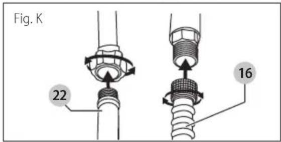
1 Connect Garden Hose to Pump
Thread the garden hose to the pump inlet.
natural_image
Diagram of a mechanical or electrical component with directional arrows indicating motion (no text or symbols)
2 Connect High Pressure Hose to Pump
Connect the high pressure hose to the pump outlet.
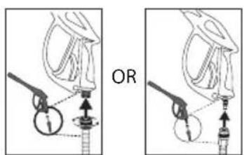
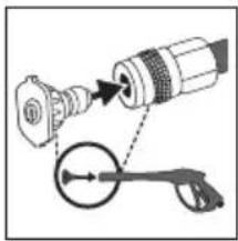
3 Connect High Pressure Hose to Spray Gun
Connect the other end of the high pressure hose to the spray gun.
ENGLISH
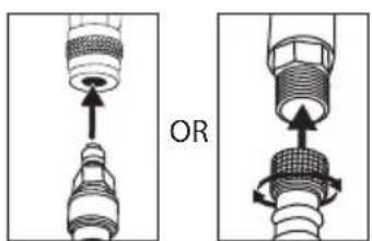
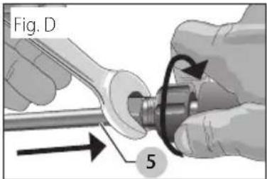
4 Connect Spray Wand to Spray Gun
Thread the spray wand into the end of the spray gun.
natural_image
Diagram showing mechanical assembly with pulley, rope, and clamped components (no text or labels)
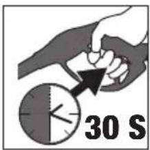
7 Release Air from System
Release all air from pump and high pressure hose by depressing trigger until a steady stream of water is present. Approximately 30 seconds.
10 Move the choke to the CLOSED position
natural_image
Pure mechanical diagram showing hoses and connectors without any text or symbols
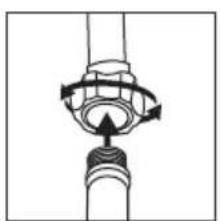
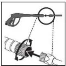
5 Connect QC Nozzles to Spray Wand
Pull quick connect coupler back and insert nozzle. Release quick connect coupler and twist nozzle to make sure it is secure in coupler.
natural_image
Diagram showing a mechanical assembly with a connector and a pulley tool (no text or symbols)
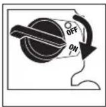
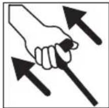
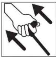
8 Verify the Engine Switch is turned to the ON Position
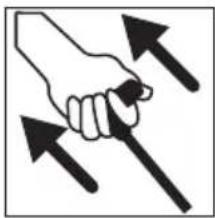
11 Pull the Recoil Starter Grip Pull the recoil starter grip to start the engine.
natural_image
Illustration of a hand gripping a screwdriver with multiple upward arrows (no text or symbols)
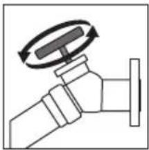
6 Turn Water Faucet Completely On
Do not run the unit without water supply connected and turned on. Use Cold Water Only.
natural_image
Diagram of a faucet with a rotating knob (no text or symbols)
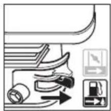
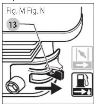
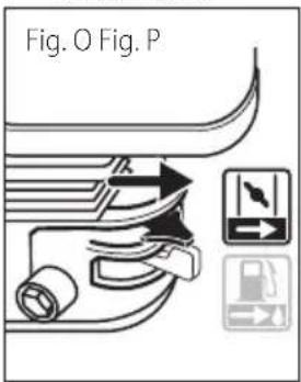
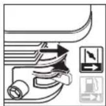
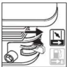
9 Place the fuel valve lever in the ON position.
natural_image
Pure mechanical diagram showing a valve mechanism with directional arrows and control buttons (no text or symbols)
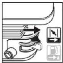
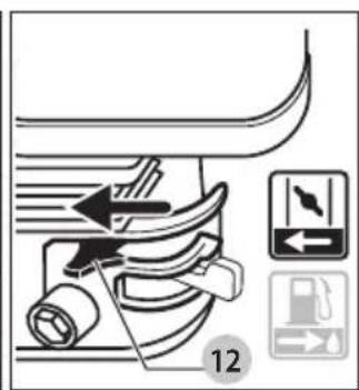
12 Move the choke to the OPEN position
natural_image
Pure mechanical component diagram without any text, numbers, or symbols
WARNING: This Guide is not a substitute for reading the operator's manual. User must read and understand operator's manual before using this product.
Engine
Refer to the engine instruction manual for location and operation of other engine controls.
Definitions: Safety Alert Symbols and Words
This instruction manual uses the following safety alert symbols and words to alert you to hazardous situations and your risk of personal injury or property damage.
NOTICE: Indicates a practice not related to personal injury which, if not avoided, may result in property damage.
Fig. A
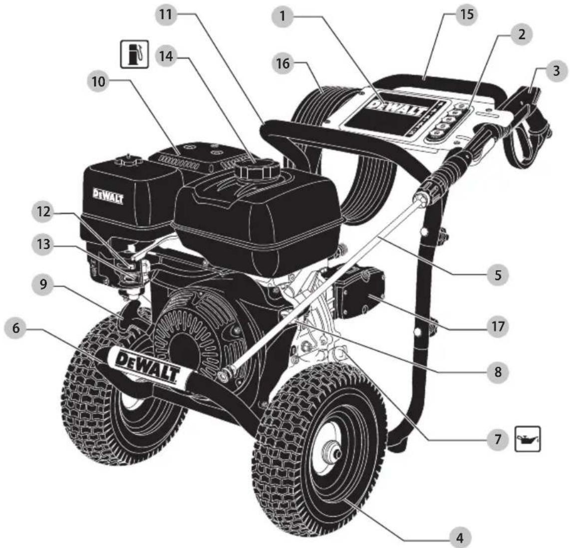
1 Panel assembly
2 Nozzle holder
3 Professional spray gun
4 Wheel
5 Quick-connect spray wand
6 Frame
7 Engine dipstick/oil plug
8 Engine switch
9 Starter grip
10 Engine
11 Secondary handle (Optional, not all models are equipped with secondary handle)
12 Choke control
13 Fuel valve lever
14 Gas cap
15 Handle assembly
16 High pressure hose
17 High pressure pump
ENGLISH
WARNING: Read all safety warnings and all instructions. Failure to follow the warnings and instructions may result in electric shock, fire and/or serious injury.

WARNING: To reduce the risk of injury, read the instruction manual.
IF YOU HAVE ANY QUESTIONS OR COMMENTS ABOUT THIS CONTACT US AT: 1-877-362-4271
Important Safety Instructions
DANGER: Carbon Monoxide. Using an engine in-dors can kill you in minutes. Engine exhaust contains high levels of carbon monoxide (CO), a poisonous gas you cannot see or smell. You may be breathing CO even if you do not smell engine exhaust.
WARNING: This product and its exhaust contain chemicals known to the State of California to cause cancer, and birth defects and other reproductive harm.
- NEVER use an engine inside homes, garages, crawlspaces or other partly enclosed areas. Deadly levels of carbon monoxide can build up in these areas. Using a fan or opening windows and doors does NOT supply enough fresh air.
- ONLY use outdoors and far away from open windows, doors and vents. These openings can pull in engine exhaust.
• Even when the engine is used correctly, CO may leak into your home. ALWAYS use a battery-powered or battery backup CO alarm in your house. Read and follow all directions for CO alarm before using. If you feel sick, dizzy or weak at anytime, move to fresh air immediately. See a doctor. You could have carbon monoxide poisoning.
WARNING: Do not operate this unit until you make this instruction manual and the engine instruction manual for safety, operation and maintenance instructions.
WARNING: When using this product basic presentations should always be followed, including the following:
- Read all instructions before using the product.
- To reduce the risk of injury, close supervision is necessary when a product is used near children.
- Know how to stop the product and bleed pressures quickly. Be thoroughly familiar with the controls.
- tay alert—watch what you are doing.
- Do not operate the product when fatigued or under the influence of alcohol or drugs.
-
Keep operating area clear of all persons.
-
Do not overreach or stand on unstable support. Keep good footing and balance at all times.
- Follow the maintenance instructions specified in the manual.
DANGER: RISK OF INJECTION OR SEVERE HISTORY. KEEP CLEAR OF NOZZLE. DO NOT DIRECT DISCHARGE STREAM AT PERSONS. THIS PRODUCT IS TO BE USED ONLY BY TRAINED OPERATORS.
WARNING: This product may not be equipped with a special arresting muffler. If the product is not equipped and will be used around flammable materials or on land covered with materials such as agricultural crops, forest, brush, grass or other similar items, then an approved spark arrester must be installed and is legally required in the state of California. It is a violation of California statutes section 130050 and/or sections 4442 and 4443 of the California Public Resources Code, unless the engine is equipped with a spark arrester, as defined in section 4442, and maintained in effective working order. Spark arresters are also required on some U.S. Forest Service land and may also be legally required under other statutes and ordinances.
WARNING: This product and its exhaust can expose you to chemicals including lead and lead compounds, and carbon monoxide, which are known to the State of California to cause cancer and birth defects or other reproductive harm. For more information go to www.P65Warnings.ca.gov.
SAVE THESE INSTRUCTIONS

GER: RISK OF EXPLOSION OR FIRE
WHAT CAN HAPPEN HOW TO PREVENT IT
- Spilled gasoline and it's vapors can become ignited from cigarette sparks, electrical arcing, exhaust gases and hot engine components such as the muffler.
- Shut off engine and allow it to cool before adding fuel to the tank.
- Use care in filling tank to avoid spilling fuel. Move pressure washer away from fueling area before starting engine.
• Heat will expand fuel in the tank which could result in spillage and possible fire explosion.
- Keep maximum fuel level 1/2" (12.7 mm) below bottom of filler neck to allow for expansion.
• Operating the pressure washer in an explosive environment could result in a fire.
• Operate and fuel equipment in well-ventilated areas free from obstructions. Equip areas with fire extinguisher suitable for gasoline fires.
• Materials placed against or near the pressure washer can interfere with its proper ventilation features causing overheating and possible ignition of the materials.
- Never operate pressure washer in an area containing dry brush or weeds.
- Muffler exhaust heat can damage painted surfaces, melt any material sensitive to heat (such as siding, plastic, rubber, vinyl or the pressure hose, itself), and damage live plants.
• Always keep pressure washer a minimum of 4' (1.2 m) away from surfaces (such as houses, automobiles or live plants) that could be damaged from muffler exhaust heat.
- Improperly stored fuel could lead to accidental ignition. Fuel improperly secured could get into the hands of children or other unqualified persons.
- Store fuel in an OSHA approved container, in a secure location away from work area.
• Use of acids, toxic or corrosive chemicals, poisons, insecticides, or any kind of flammable solvent with this product could result in serious injury or death.
• Do not spray flammable liquids.

GER: RISK TO BREATHING (ASPHYXIATION
What CAn hAPPEn hOW TO PREVEnT iT
- Breathing exhaust fumes will cause serious injury or death! Engine exhaust contains carbon monoxide, an odorless and deadly gas.
- Operate pressure washer in a well-ventilated area. Avoid enclosed areas such as garages, basements, etc.
- Never operate unit in or near a location occupied by humans or animals.
• Some cleaning fluids contain substances which could cause injury to skin, eyes or lungs.
- Use only cleaning fluids specifically recommended for high pressure washers. Follow manufacturers recommendations. Do not use chlorine bleach or any other corrosive compound.
DANGER: RISK OF FLUID INJECTION AND LADRATION
What CAn hAPPEn hOW TO PREVEnT iT
- Your pressure washer operates at fluid pressures and velocities high enough to penetrate human and animal flesh which could result in amputation or other serious injury. Leaks caused by loose fittings or worn or damaged hoses can result in injection injuries. DO NOT TREAT FLUID INJECTION AS A SIMPLE CUT! See a physician immediately!
- Inspect the high pressure hose regularly. Replace the hose immediately if it is damaged, worn, has melted from contacting the engine, or shows any signs of cracks, bubbles, pinholes, or other leakage. Never grasp a high pressure hose that is leaking or damaged.
- Never touch, grasp or attempt to cover a pinhole or similar water leak on the high pressure hose. The stream of water IS under high pressure and WILL penetrate skin.
- Never place hands in front of nozzle.
- Your pressure washer operates at fluid pressures and velocities high enough to penetrate human and animal flesh which could result in amputation or other serious injury. Leaks caused by loose fittings or worn or damaged hoses can result in injection injuries. DO NOT TREAT FLUID INJECTION AS A SIMPLE CUT! See a physician immediately! (CONTINUED)
- Direct spray away from self and others.
• Make sure hose and fittings are tightened and in good condition. Never hold onto the hose or fittings during operation.
- Do not allow hose to contact muffler.
- Never attach or remove wand or hose fittings while system is pressurized.
- When using replacement lances or guns with this pressure washer, do not use a lance and/or lance/gun combination that is shorter in length than what was provided with this pressure washer as measured from the nozzle end of the lance to the gun trigger.
- Injuries can result if system pressure is not reduced before attempting maintenance or disassembly.
• To relieve system pressure, shut off engine, turn off water supply and pull gun trigger until water stops flowing.
- Use only accessories rated equal to or higher than the rating of the pressure washer.

DANGER: RISK OF INJURY FROM SPRAY
What CAn hAPPEn hOW TO PREVEnT iT
• High-velocity fluid spray can cause objects to break, projecting particles at high speed.
• Always wear ANSI-approved Z87.1 safety glasses. Wear protective clothing to protect against accidental spraying.
- Never point wand at or spray people or animals.
• Light or unsecured objects can become hazardous projectiles.
• Always secure trigger lock when wand is not in service to prevent accidental operation.
- Never permanently secure trigger in pull-back (open) position.

- Unsafe operation of your pressure washer could lead to serious injury or death to you or others.
- Do not use chlorine bleach or any other corrosive compound.
- Become familiar with the operation and controls of the pressure washer.
- Keep operating area clear of all persons, pets and obstacles.
- Do not operate the product when fatigued or under the influence of alcohol or drugs. Stay alert at all times.
• Never compromise the safety features of this product.
- Do not operate machine with missing, broken or unauthorized parts.
- Never leave wand unattended while unit is running.
• If proper starting procedure is not followed, engine can kickback causing serious hand and arm injury.
- If engine does not start after two pulls, squeeze trigger of gun to relieve pump pressure. Pull starter cord slowly until resistance is felt. Then pull cord rapidly to avoid kickback and prevent hand or arm injury.
- The spray gun/wand is a powerful cleaning tool that could look like a toy to a child.
- Keep children away from the pressure washer at all times.
- Reactive force of spray will cause gun/wand to kickback, and could cause the operator to slip or fall or misdirect the spray. Improper control of gun/wand can result in injuries to self and others.
- Do not overreach or stand on an unstable support.
- Do not use pressure washer while standing on a ladder.
- Grip gun/wand firmly with both hands. Expect the gun to kickback when triggered.

DANGER: RISK OF INJURY OR PROPERTY DAMAGE WHEN TRANSPORTING OR STORING
What CAn hAPPEn hOW TO PREVEnT iT
- Fuel or oil can leak or spill and could result in fire or breathing hazard. Serious injury or death can result. Fuel or oil leaks will damage carpet, paint or other surfaces in vehicles or trailers.
- Oil could fill the cylinder and damage the engine if the unit is not stored or transported in an upright position.
- If pressure washer is equipped with a fuel shut-off valve, turn the valve to the off position before transporting to avoid fuel leaks. If pressure washer is not equipped with a fuel shut-off valve, drain the fuel from tank before transporting. Only transport fuel in an OSHA-approved container. Always place pressure washer on a protective mat when transporting to protect against damage to vehicle from leaks. Always transport and store unit in an upright position. Remove pressure washer from vehicle immediately upon arrival at your destination.


- Spray directed at electrical outlets or switches, or objects connected to an electrical circuit, could result in a fatal electrical shock.
- Unplug any electrically operated product before attempting to clean it. Direct spray away from electric outlets and switches.


IGER: RISK OF CHEMICAL BURN
What CAn hAPPEn hOW TO PREVEnT iT
• Use of acids, toxic or corrosive chemicals, poisons, insecticides, or any kind of flammable solvent with this product could result in serious injury or death.
- Do not spray acids, gasoline, kerosene, or any other flammable materials with this product. Use only household detergents, cleaners and degreasers recommended for use with pressure washers.
- Wear protective clothing to protect eyes and skin from contact with sprayed materials.

RNING: RISK OF BURSTING
What CAn hAPPEn hOW TO PREVEnT iT
• Over inflation of tires could result in serious injury and property damage.
- Use a tire pressure gauge to check the tires pressure before each use and while inflating tires; see the tire sidewall for the correct tire pressure.
NOTE: Air tanks, compressors and similar equipment used to inflate tires can fill small tires similar to these very rapidly. Adjust pressure regulator on air supply to no more than the rating of the tire pressure. Add air in small increments and frequently use the tire gauge to prevent over inflation.
• High-velocity fluid spray directed at pneumatic tire sidewalls (such as found on automobiles, trailers and the like) could damage the sidewall resulting in serious injury.
- On pressure washers rated above 1600 psi (11032 kPa) use the widest fan spray (40° nozzle) and keep the spray a minimum of 8" (200 mm) from the pneumatic tire sidewall. Do not aim spray directly at the joint between the tire and rim.


NING: RISK OF HOT SURFACES
What CAn hAPPEn hOW TO PREVEnT iT
- Contact with hot surfaces, such as engines exhaust components, could result in serious burn.
- During operation, touch only the control surfaces of the pressure washer. Keep children away from the pressure washer at all times. They may not be able to recognize the hazards of this product.
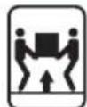

NING: RISK OF INJURY FROM LIFTING
What CAn hAPPEn hOW TO PREVEnT iT
• Serious injury can result from attempting to lift too heavy an object.
• The pressure washer is too heavy to be lifted by one person. Obtain assistance from others before lifting.
SAVE THESE INSTRUCTIONS FOR FUTURE USE
INSTALLATION
Pressure Washer Assembly (Fig. A–F)
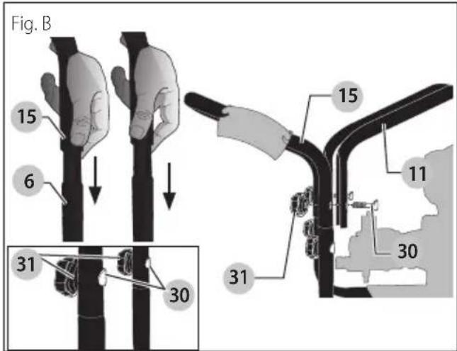
- Slide the handle assembly 15 onto the frame 6. Align holes, insert saddle bolts 30 and secure in place with knobs 31. Tighten until snug.

ION: Risk of personal injury. Avoid placing between handle and frame when assembling vent pinching.
-
Align holes in the secondary handle 11 (if equipped) with the mounting holes in the handle assembly 15.
-
Insert saddle bolts 30 through aligned holes and secure secondary handle (if equipped) to handle assembly with knobs 31. Tighten until snug.
ENGLISH
- Attach high pressure hose 16 to spray gun. Make sure it is secure.
- Connect wand 5 to spray gun. Make sure connection is secure.
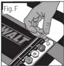
- Place the nozzle holder 2 onto the panel assembly 1 and push each nozzle holder into place.
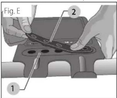
- Remove the five colored quick-connect nozzles from the plastic bag and insert them into correct grommet on the nozzle holder. Nozzles are color coded to match colored nozzles on panel assembly.
NOTE: The high pressure pump was filled with oil at the factory. Always check oil level before using (refer to Maintenance for more information).
WARNING: Risk of bursting. Use a tire pressure gauge to check the tires pressure before each use and while inflating tires; see the tire sidewall for the correct tire pressure.
NOTE: Air tanks, compressors and similar equipment used to inflate tires can fill small tires similar to these very rapidly. Adjust pressure regulator on air supply to no more than the rating of the tire pressure. Add air in small increments and frequently use the tire gauge to prevent over inflation.
OPERATION
Pressure Adjustments
The pressure setting is preset at the factory to achieve optimum pressure and cleaning. To lower the pressure, follow these instructions.
- Back away from the surface to be cleaned. The further away you are, the less the pressure will be on the surface to be cleaned.
- Change to the 40° nozzle (white). This nozzle delivers a less powerful stream of water and a wider spray pattern. Refer to Spray Wand Nozzles.
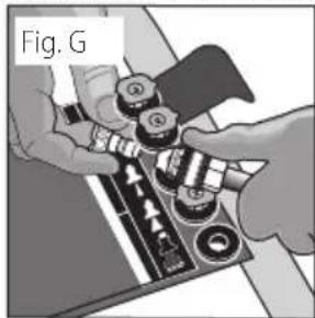
Spray Wand Nozzles (Fig. A, G)
The nozzles for the spray wand are stored in the nozzle holder 2 on the panel assembly 1. Colors on the panel identify nozzle location and spray pattern. Refer to the following chart to choose the correct nozzle for the job to be performed.
| Nozzle Color | Spray Pattern Uses Surfaces*** |
| Red | 0° | powerful pinpoint for very intense cleaning | metal or concrete;DO NOT use on wood |
| Yellow | 15° | intense cleaning of small areas | metal, concrete or wood |
| Green | 25° | intense cleaning of larger areas | metal, concrete or wood |
| White | 40° | covers wide areas of cleaning | metal, concrete,wood or vinyl |
| Black | low pressure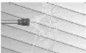 | applies cleaning solutions | metal, concrete,wood or vinyl |
*** NOTICE: The high pressure spray from your pressure washer is capable of causing damage to surfaces such as wood, glass, automobile paint, auto striping and trim, delicate objects such as flowers and shrubs. Before spraying, check the item to be cleaned to assure yourself that it is strong enough to resist damage from the force of spray.
Changing Nozzles on Spray Wand (Fig. G)
DANGER: Risk of fluid injection. Do not direct a charge stream toward persons, unprotected skin, eyes or any pets or animals. Serious injury will occur.
WARNING: Flying objects could cause risk of serious injury. Do Not attempt to change nozzles while pressure washer is running. Turn engine off before changing nozzles.
-
Pull quick-connect coupler back and insert nozzle.
-
Release quick-connect coupler and twist nozzle to make sure it is secure in coupler.
WARNING: Flying object could cause risk of serious injury. Ensure nozzle is completely inserted in quick-connect socket and quick-connect collar is fully engaged (forward) before squeezing gun trigger.
natural_image
Close-up of hands assembling mechanical parts with a tool (no visible text or symbols)
Chemicals and Cleaning Solvents
Applying chemicals or cleaning solvents is a low-pressure operation.
NOTE: Use only soaps and chemicals designed for pressure washer use. Do not use bleach.
To Apply Chemicals and Solvents (Fig. H)
- Press chemical hose 19 onto barbed fitting located near high pressure hose connection of pump as shown.
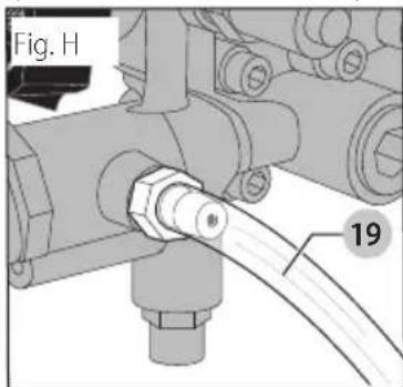
- Place the other end of chemical hose with filter into the container holding chemical/cleaning solution.
NOTE: For every 10 gallons (38 liters) of water pumped 1 gallon (3.8 liters) of chemical/cleaning solution will be used.
- Install low-pressure (black) nozzle into quick connect fitting of spray wand, refer to Spray Wand Nozzles.
NOTE: Chemicals and soaps will not siphon if the black soap nozzle is not installed on the spray wand.
- After use of chemicals, place chemical hose into container of clean water and draw clean water through chemical injection system to rinse system thoroughly
NOTICE: Risk of property damage. Failure to do so could cause damage to the pump. Pumps damaged due to chemicals will not be covered under warranty.
Starting
WARNING: To reduce the risk of injury, read the pressure washer instruction manual and the engine instruction manual before starting pressure washer.
DANGER: Risk of fluid injection and laceration. When using the high pressure setting, DO NOT allow the high pressure spray to come in contact with unprotected skin, eyes, or with any pets or animals. Serious injury will occur.
- Your washer operates at fluid pressures and velocities high enough to penetrate human and animal flesh, which could result in amputation or other serious injury. Leaks caused by loose fittings or worn or damaged hoses can result in injection injuries. DO NOT TREAT FLUID INJECTION AS A SIMPLE CUT! See a physician immediately!
DANGER: Carbon Monoxide. Using an engine inductors can kill you in minutes. Engine exhaust contains high levels of carbon monoxide (CO), a poisonous gas you cannot see or smell. You may be breathing CO even if you do not smell engine exhaust.
- Breathing exhaust fumes will cause serious injury or death! Engine exhaust contains carbon monoxide, an odorless and deadly gas.
- Operate pressure washer in a well-ventilated area. Avoid enclosed areas such as garages, basements, etc.
- Never operate unit in or near a location occupied by humans or animals.
WARNING: Risk of fire, asphyxiation and burning. Note: Fill fuel tank when engine is running or hot. Do not smoke when filling fuel tank.
- Never fill fuel tank completely. Fill tank to 1/2" (12.7 mm) below bottom of filler neck to provide space for fuel expansion. Wipe any fuel spillage from engine and equipment before starting engine.
- DO NOT let hoses come in contact with very hot engine muffler during or immediately after use of your pressure washer. Damage to hoses from contact with hot engine surfaces will NOT be covered by warranty.
NOTICE: NEVER pull water supply hose to move pressure washer. This could damage hose and/or pump inlet.
• DO NOT use hot water, use cold water only.
English
- Never turn water supply off while pressure washer engine is running or damage to pump will result.
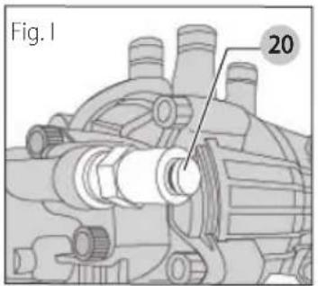
- DO NOT stop spraying water for more than two minutes at a time. Pump operates in bypass mode when spray gun trigger is not pressed. When the temperature inside the pump rises too high the thermal relief valve (20, Fig. 1) will open and release a gush of water in an effort to lower the temperature inside the pump. The thermal relief valve will then close. If pump is left in bypass mode for more than two minutes internal components of the pump can be damaged.
Start-up Procedure (Fig. A, J–P)
- In a well-ventilated outdoor area, add fresh, high-quality, unleaded gasoline with a pump octane rating of 86 or higher. Do not overfill. Wipe up spilled fuel before starting the engine. Refer to engine instruction manual for correct procedure.
IMPORTANT: Ethanol Shield™ (sold separately) is a fuel stabilizer that helps eliminate and prevent ethanol related problems in power equipment. Follow the instructions on the container and add to the gasoline.
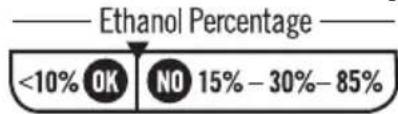
NOTICE: Use of fuels with greater than 10% ethanol are not approved for use in this product per EPA regulations and will damage the unit and void the warranty.
- Check engine oil level. Refer to the engine instruction manual for correct procedure.
- Connect the water hose to the water source. Turn the water source on to remove all air from the hose. When a steady stream of water is present, turn the water source off.
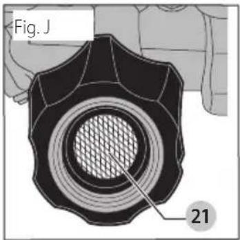
- Verify the filter screen 21 is in water inlet of pump. The convex side faces out.
NOTICE: Failure to use an inlet screen filter may cause damage to pump components and void warranty.
- Connect the cold water source 22 to pump inlet.
NOTE: Water source must provide a minimum of 5 gallons per minute at 20 psi (138 kPa).
WARNING: To reduce the possibility of contamination allows protect against backflow when connected to a potable water system.
- Connect high pressure hose 16 to pump outlet.
- If applying a chemical or cleaning solution, refer to Chemicals and Cleaning Solvents.
- Turn the water source on.
NOTICE: Risk of property damage. Failure to do so could cause damage to the pump.
- Remove all air from the pump and high pressure hose by depressing trigger until a steady stream of water is present.
- Turn the engine ON/OFF switch 8 to the ON position.
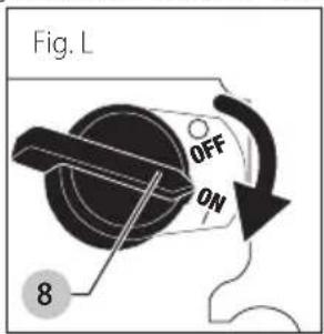
- Place the fuel valve lever 13 in the ON position.
- If the engine is cold, move the choke 12 to the CLOSED position as shown.
WARNING: Risk of unsafe operation. Pull starter grip slowly until resistance is felt. Then pull starter grip 9 rapidly to avoid kickback and prevent hand or arm injury.
NOTE: Do not allow the starter grip to snap back. Return it gently by hand.
WARNING: Risk of unsafe operation. If engine does not start after two pulls, squeeze trigger of gun to relieve pump pressure. Pull starter cord slowly until resistance is felt. Then pull cord rapidly to avoid kickback and prevent hand or arm injury.
NOTE: If the oil level in the engine is low, the engine will not start. If the engine does not start, check the oil level and add oil as needed.
- As the engine warms up, move the choke to the open position.
natural_image
Mechanical linkage diagram showing a lever and bracket (no text or symbols)
- Depress trigger on gun to start water flow.
WARNING: Do not allow the unit to run for more than two minutes without the gun trigger being pulled. This could cause overheating and damage to the pump. When the temperature inside the pump rises too high, the thermal relief valve will open and release a spray of water from the pump to lower the internal temperature. The valve will then close.
WARNING: Risk of unsafe operation. Stand on a stable surface and grip gun/wand firmly with both hands. Expect the gun to kickback when triggered.
- Release trigger to stop water flow.
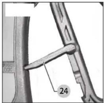
DANGER: Risk of injury from spray. Engage the trigger lock 24 when gun is not in use to prevent accidental spraying.
- Adjust spray for the task being performed by changing quick connect nozzle. Refer to Spray Wand Nozzles.
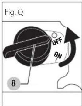
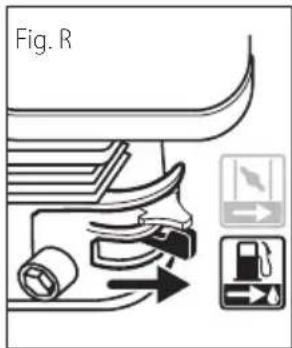
Shutting Down (Fig. Q, R)
- If chemicals were applied, place the chemical hose into a container of clean water and draw clean water through chemical injection system to rinse system thoroughly.
NOTICE: Risk of property damage Failure to do so could cause damage to the pump.
-
Place the engine ON/OFF switch 8 to the OFF Position.
-
Place the fuel valve lever 13 in the OFF position.
NOTICE: Risk of property damage. Never turn water supply off while pressure washer engine is running or damage to pump will result.
-
Turn water source off.
-
Pull trigger on spray gun to relieve any water pressure in hose or spray gun.
-
Refer to Storage for proper storage procedures.
MAINTENANCE
WARNING: Risk of burning. When performing maintenance, you may be exposed to hot surfaces, water pressure or moving parts that can cause serious injury or death.
WARNING: Risk of fire. Always disconnect, spark plug wire, let the engine cool and release all water pressure before performing any maintenance or repair. The engine contains flammable fuel. Do not smoke or work near open flames while performing maintenance.
To ensure efficient operation and longer life of your pressure washer, a routine maintenance schedule should be prepared and followed. If the pressure washer is used in unusual conditions, such as high temperatures or dusty conditions, more frequent maintenance checks will be required.
Engine
Consult the engine instruction manual for the manufacturer's recommendations for any and all maintenance.
NOTE: The pressure washer frame is equipped with an oil drain hole to help make changing the engine oil easier.
Pump
The pump on this unit is maintenance free and requires no oil. If there is a problem with the pump, contact our Customer Service Group as soon as possible.
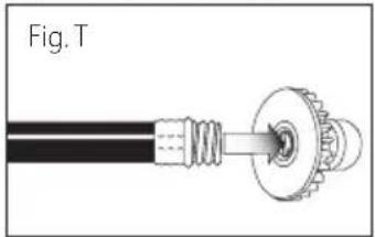
Nozzle Cleaning (Fig. S, T)
If the nozzle becomes clogged with foreign materials, such as dirt, excessive pressure may develop. If the nozzle becomes partially clogged or restricted, the pump pressure will pulsate. Clean the nozzle immediately using the nozzle kit supplied and the following instructions:
- Shut off the pressure washer and turn off the water supply.
- Pull trigger on gun handle to relieve any water pressure.
- Disconnect the spray wand from the gun.
English
- Remove the high pressure nozzle from the spray wand. Remove any obstructions with the nozzle cleaning tool 25 provided and back flush with clean water.
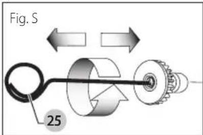
- Direct water supply into spray nozzle to back flush loosened particles for 30 seconds.
natural_image
Mechanical assembly diagram showing a shaft connected to a gear and housing (no text or symbols)
- Reassemble the nozzle to the wand.
- Reconnect spray wand to gun then turn on water supply.
- Start pressure washer and place spray wand into high pressure setting to test.
To Clean the Water Inlet Filter (Fig. J)
This filter screen 21 should be checked periodically and cleaned if necessary.
- Remove the filter screen 21 by grasping the end and removing it from water inlet of pump.
- Clean filter by flushing it with water on both sides.
- Reinsert filter into water inlet of pump. Convex side faces out.
nOTE: Do not operate pressure washer without filter properly installed.
STORAGE
Engine
Consult the engine instruction manual for the manufacturer's recommendations for storage.
- Add Ethanol Shield™ fuel stabilizer following the manufacturer's instructions. When adding a gasoline stabilizer, fill the fuel tank with fresh gasoline. If only partially filled, air in the tank will promote fuel deterioration during storage. If you keep a container of gasoline for refueling, be sure that it contains only fresh gasoline.
- After adding a gasoline stabilizer, run the engine outdoors for 10 minutes to be sure that treated gasoline has replaced the untreated gasoline in the carburetor.
- Turn the fuel valve to the OFF position.
- Continue to run the engine until it stops from the lack of fuel in the carburetor fuel bowl. Running time should be less than 3 minutes.
Pump
The manufacturer recommends using DEWALT Pump Guard or equivalent when storing the unit for more than 30 days and/or when freezing temperatures are expected. DEWALT Pump Guard is environmentally friendly.
NOTE: Using pump guard helps provide proper lubrication to the internal seals of the pump regardless of temperature or environment.
NOTICE: Risk of property damage. Use only DEWALT Pump Guard or equivalent. Other products could be corrosive and/or contain alcohol which may cause pump damage.
- Turn off pressure washer and disconnect hoses from pump.
- Unscrew bottle valve from Pump Guard bottle and remove seal.
- Screw bottle valve back onto bottle.
- Attach bottle to water inlet of pump.
- Squeeze bottle to inject contents into pump.
- With ignition switch off, simultaneously pull starter rope and squeeze bottle. Repeat until protector fluid exits pump outlet. NOTE: This step may require two people.
Pressure Washer
- Drain all water from high pressure hose, coil it and store it in cradle of the pressure washer handle.
- With nozzle pointed down and the spray gun and wand in a vertical position, squeeze trigger to drain all water from spray gun and wand. Store in gun holder.
- Store chemical hose so it is protected from damage.
CAUTION: Risk of personal injury. Avoid placing hands between handle and frame when assembling to prevent pinching.
NOTICE: Risk of property damage. Always store and transport unit in an upright position.
ACCESSORIES
Recommended accessories for use with your tool are available for purchase from your local dealer or authorized service center. If you need assistance in locating any accessory for your tool, please contact the FNA Group at cservice@fna-group.com, 7152 99th Street Pleasant Prairie, WI 53158, or call 1-877-362-4271.
DANGER: Risk of fluid injection. When using replacement lances or guns with this pressure washer, do not use a lance and/or lance/gun combination that is shorter in length than what was provided with this pressure washer as measured from the nozzle end of the lance to the gun trigger.
WARNING: The use of any other accessory not recommended for use with this tool could be hazardous. Use only accessories rated equal to or higher than the rating of the pressure washer.
Please have the following information available for all service calls: Model Number ____
Serial Number ____
Date and Place of Purchase ____
Repairs
To assure product SAFETY and RELIABILITY, repairs, maintenance and adjustment should be performed by a FNA factory service center, a FNA authorized service center or other qualified service personnel. Always use identical replacement parts.
Limited Warranty
The manufacturer of this product agrees to repair or replace designated parts that prove defective within the warranty period listed below at the manufacturer's sole discretion. Specific limitations/extensions and exclusions apply.
This warranty covers defects in material and workmanship and not parts failure due to normal wear, depreciation, abuse, accidental damage, negligence, improper use, maintenance, water quality or storage. To make a claim under the terms of the warranty, all parts said to be defective must be retained and available for return upon request to a designated Warranty Service Center for warranty inspection. The judgments and decisions of the manufacturer concerning the validity of warranty claims are final.
These warranties pass through to the end user and are non-transferable. As a factory authorized and trained Warranty Service Center, the factory will honor the terms of all component warranties and satisfy claims of the appropriate warranty provisions.
Normal wear items include, but are not limited to, valves and seals, which are not covered by this warranty.
This warranty replaces all other warranties, express or implied, including without limitation any warranties of merchantability or fitness for a particular purpose and all such warranties are hereby disclaimed and excluded by the manufacturer. The manufacturer's warranty obligation is limited to repair and replacement of defective products as provided herein and the manufacturer shall not be liable for any further loss, damages, or expenses – including damages from shipping, accident, abuse, acts of God, misuse, or neglect. Neither is damage from repairs using parts not purchased from the manufacturer or alterations performed by non-factory authorized personnel. Failure to install and operate equipment according to the guidelines put forth in the instruction manual shall void warranty.
This warranty does not cover the following:
machines used for rental purposes, damage resulting from shipping (claims must be filed with freighter), accident, abuse, act of God, misuse, or neglect. Neither is damage from repairs or alterations performed by non-factory authorized personnel or failure to install and operate equipment according to the guidelines put forth in the instruction manual.
The manufacturer will not be liable to any persons for consequential damage, for personal injury, or for commercial loss.
Responsibility of Original Purchaser (Initial User):
- To process a warranty claim on your DEWALT pressure washer, report the concern to 1-877-362-4271 or cservice@fna-group.com for authorization and direction to the nearest authorized service centre in your area.
- Retain original cash register sales receipt as proof of purchase for warranty work.
- Use reasonable care in the operation and maintenance of the product as described in the Owners Manual(s).
Warranty Does Not Apply to Failures Due to:
- Merchandise sold as reconditioned, used as rental equipment, used for commercial purposes or commercial applications, or floor or display models. Freight damage
- Damage due to chemical deterioration, scale build up, rust, corrosion or thermal expansion
- Freeze damage
- Damage caused by parts or accessories not obtained from an authorized dealer or not approved by the manufacturer.
- Normal wear of moving parts or components affected by moving parts.
Engine and Emissions Control System
Covered by engine manufacturer warranty. See engine manual.
High Pressure Pump (defects in material and workmanship)
Three (3) years from date of purchase
Frame (defects in material and workmanship)
Five (5) years from date of purchase.
Accessories (Defects in Material and Workmanship)
Includes nozzles, hoses, spray guns, wands, tires, feet Ninety (90) days from date of purchase.
ENGLISH
Glossary
Bypass mode: Allows water to re-circulate within pump when the gun trigger is not pulled.
Chemical hose: Feeds cleaning agents into the pump to mix with the water. Refer to Chemicals and
Cleaning Solvents.
Chemical injection system: Mixes cleaners or cleaning solvents with water to improve cleaning effectiveness.
Choke control: Opens and closes carburetor choke valve.
CU: Cleaning Units. GPM multiplied by psi. (GPM x PSI = CU)
Fuel valve lever: Opens/closes connection between fuel tank and carburetor.
GPM*: Gallons Per Minute. The unit of measure for the flow rate of water.
PSI*: Pounds per Square Inch. The unit of measure for water pressure. Also used for air pressure, hydraulic pressure, etc.
* Complies with CETA Performance Standard CPC-100.
kPa (kilopascal): Metric pressure measurement. 1 kilopascal equal 1000 pascals.
Quick-connect spray wand: Allows the user to quickly change out high pressure nozzles. Refer to Spray
Wand Nozzles.
Thermal relief valve: When the temperature inside the pump rises too high the valve will open and release a gush of water in an effort to lower the temperature inside the pump. The valve will then close.
Water supply: All pressure washers must have a source of water. The minimum requirements for a water supply are 20 psi (138 kPa) and 5 gallons per minute.
Troubleshooting Guide
This section provides a list of the more frequently encountered malfunctions, their causes and corrective actions. The operator or maintenance personnel can perform some corrective actions, and others may require the assistance of a qualified FNA technician or your dealer.
Problem Code
| Engine will not start | 1, 2, 3, 4, 5, 6, 7, 8, 29 (refer to the engine's instruction manual for further engine troubleshooting) |
| No or low pressure (initial use) | 9, 10, 11, 12, 13, 14, 15, 16 |
| Will not draw chemicals | 16, 17, 18, 19, 20, 21 |
| No or low pressure (after period of normal use) | 22, 23, 24 |
| Water leaking at gun/spray wand connection | 25, 26 |
| Water leaking at pump | 25, 26, 27, 28 |
| Pump Pulsates | 12 |
Troubleshooting Codes
| CODE POSSIBLE CAUSE POSSIBLE SOLUTION |
| 1 No fuel. Add fuel. |
| 2 Low oil. Add required amount of oil. |
| 3 Pressure builds up after two pulls on the recoil starter or after initial use. | Squeeze gun trigger to relieve pressure. |
| 4 | Choke lever in the NO CHOKE position. | Move choke to the CHOKE position. |
| 5 Spark plug wire not attached. | Attach spark plug wire. |
| 6 | Engine ON/OFF switch in OFF position. | Place engine ON/OFF switch in ON position. |
| 7 Choke lever in the CHOKE position on a hot engine or an engine that has been exposed to thermal heat for a long period of time. | Move choke to the NO CHOKE position. |
| 8 | Fuel valve CLOSED. | Move the fuel valve lever to the OPEN position. |
| 9 | Spray wand not in high pressure. | See Spray Wand Nozzles under Operation. |
CODE POSSIBLE CAUSE POSSIBLE SOLUTION
| 10 Low water supply. Water supply must be at least 5 GPM @ 20 psi (138 kPa). |
| 11 Leak at high pressure hose fitting. Repair leak. Apply sealant tape if necessary. |
| 12 | Nozzle obstructed. | See Nozzle Cleaning under Maintenance. |
| 13 | Water filter screen clogged. | Remove and clean filter. See To Clean the Water Inlet Filter under Maintenance. |
| 14 | Air in hose. | Turn off the engine, then the water source. Disconnect the water source from the pump inlet and turn the water source on to remove all air from the hose. When there is a steady stream of water present, turn water source off. Recon necl water source to pump inlet and turn on wa ter source. Squeeze trigger to removeremainingair. |
| 15 Choke lever in the CHOKE position. Move choke to the NO CHOKE po si tion. |
| 16 | High pressure hose is too long. | Use high pressure hose under 100 feet (30.48 m). Lengthen water supply hose instead of high pressure hose. |
| 17 | Spray wand not in low pressure. | See Spray Wand Nozzles under Operation. |
| 18 Chemical filter clogged. Clean filter. |
| 19 | Chemical screen not in cleaning solution. | Make sure end of chemical hose is fully submerged into cleaning solution. |
| 20 Chemical too thick. Dilute chemical. Chemical should be the same consistency as water. |
| 21 | Worn seal or packing. | Have parts cleaned or replaced by authorized service center. |
| 22 | Chemical build up in chemical injector. | Have replaced by an authorized service center. |
| 23 | Worn or obstructed valves. | Have replaced by authorized service center. |
| 24 Worn unloader piston. | Have replaced by authorized service center. |
| 25 Worn or broken o-ring. | Check and replace. |
| 26 Loose hose connection. | Tighten. |
| 27 Piston packings worn. | Have replaced by authorized service center. |
| 28 | Pump head or tubes damaged from freezing. | Have replaced by authorized service center. |
| 29 | Air filter filled with oil. | Clean air filter element. Refer to engine instruction manual for correct procedure. |
GUIDE D'INSTALLATION RAPIDE
natural_image
Illustration showing three-step mechanical assembly: hand holding a vertical rod, pin adjustment, and bracket assembly (no text or symbols)
natural_image
Mechanical assembly diagram showing engine components and a highlighted oil drop component (no text or labels)
C Ajouter l'essence
natural_image
Pure mechanical diagram showing a lever mechanism without any text or symbols
natural_image
Diagram showing a lever mechanism with pulley and rope, no text or symbols present
natural_image
Diagram showing a mechanical component with a circular arrow indicating direction, no text or symbols present
natural_image
Simple line drawing of a faucet with a rotating knob (no text or symbols)
natural_image
Pure mechanical diagram showing a valve or spring mechanism without any text, numbers, or symbols
natural_image
Pure mechanical diagram showing a valve or spring mechanism without any text, numbers, or symbols
natural_image
Illustration of a hand gripping a tool with multiple arrows pointing upward (no text or symbols)
natural_image
Pure mechanical diagram showing a valve and shaft assembly without any text, numbers, or symbols
natural_image
Close-up of hands assembling mechanical parts with a tool (no visible text or symbols)
natural_image
Mechanical component diagram showing a lever and bracket assembly (no text or symbols)
natural_image
Mechanical assembly diagram showing a shaft connected to a gear and housing (no text or symbols)
natural_image
Illustration showing two hand positions adjusting a tool, with no visible text or symbols
B Agregue/revise el aceite
El motor viene sin aceite.
natural_image
Mechanical assembly diagram showing components and a highlighted oil drop icon (no text or labels)
C Agregue gasolina
natural_image
Line drawing of a kitchen appliance with hands operating the button (no text or symbols)
natural_image
Pure mechanical diagram showing a rotating component with arrows indicating direction (no text or symbols)
4 Conecte la vara rociadora a la pistola rociadora
natural_image
Two technical diagrams showing a mechanical component being inserted into a housing, with no visible text or symbols.
natural_image
Two diagrams showing a mechanical device with pulleys and weights, no text or symbols present
natural_image
Diagram showing a lever mechanism with a pulley and rope, no text or symbols present
natural_image
Diagram showing a mechanical assembly with a connector and a lever mechanism (no text or symbols)
natural_image
Diagram of a faucet with a rotating knob (no text or symbols)
natural_image
Pure mechanical diagram showing gear and component assembly without any text or symbols
natural_image
Pure mechanical diagram showing a valve or pump assembly with directional arrows and icons (no text or symbols)
natural_image
Illustration of a hand holding a tool with multiple arrows pointing outward (no text or symbols)
natural_image
Pure mechanical diagram showing fluid flow paths with no text or symbols
natural_image
Close-up of hands assembling mechanical parts (no visible text or symbols)
natural_image
Mechanical assembly diagram showing a lever and pin (no text or symbols)
natural_image
Diagram of a mechanical connector with a central shaft and threaded end (no text or symbols)
The FNA Group, Inc., 7152 99th Street Pleasant Prairie, WI 53158
(MAR) Part No. 7115347 Copyright © 2021
The following are trademarks for one or more DEWALT power tools: the yellow and black color scheme, the "D" shaped air intake grill, the array of pyramids on the handgrip, the kit box configuration, and the array of lozenge-shaped humps on the surface of the tool.
DEWALT ^® , GUARANTEED TOUGH ^® and the yellow and black color scheme are trademarks the DEWALT Industrial Tool Co., used under license.
SIMPSON ^® and AAA ^TM are registered trademarks of the FNA Group, Inc.
The FNA Group, Inc., 7152 99th Street Pleasant Prairie, WI 53158, a licensee of DEWALT Industrial Tools