
TTW-12CR2/UF - Air-conditioner TCL - Free user manual and instructions
Find the device manual for free TTW-12CR2/UF TCL in PDF.

| Product Type | Through-the-wall air conditioner (TTW) |
| Brand | TCL |
| Model | TTW-12CR2/UF |
| Cooling Capacity | 12,000 BTU/h |
| Main Functions | Cooling, Heating, Dehumidification, Fan, Auto, ECO, Sleep |
| Fan Speeds | High, Medium, Low, Auto |
| Temperature Range | 16 °C to 31 °C (61 °F to 88 °F) |
| Timer | Programmed On/Off from 0.5 to 24 hours |
| Power Supply | 120 V, 60 Hz, 3-prong grounded plug |
| Electrical Protection | LCDI power cord with leakage current detection |
| Air Filter | Washable, monthly check recommended |
| Digital Display | Room or set temperature, timer time |
| Remote Control | Included, AAA batteries |
| Installation | In existing or new wall sleeve, requires backward tilt |
| Cleaning | Filter: wash with soapy water; cabinet: damp cloth |
| Safety | Grounding required, do not use extension cord |
Frequently Asked Questions - TTW-12CR2/UF TCL
User questions about TTW-12CR2/UF TCL
0 question about this device. Answer the ones you know or ask your own.
Ask a new question about this device
Download the instructions for your Air-conditioner in PDF format for free! Find your manual TTW-12CR2/UF - TCL and take your electronic device back in hand. On this page are published all the documents necessary for the use of your device. TTW-12CR2/UF by TCL.
USER MANUAL TTW-12CR2/UF TCL
Operating Instructions
natural_image
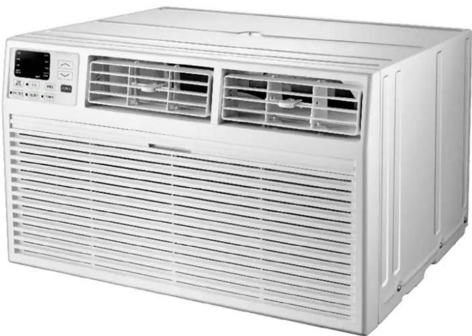
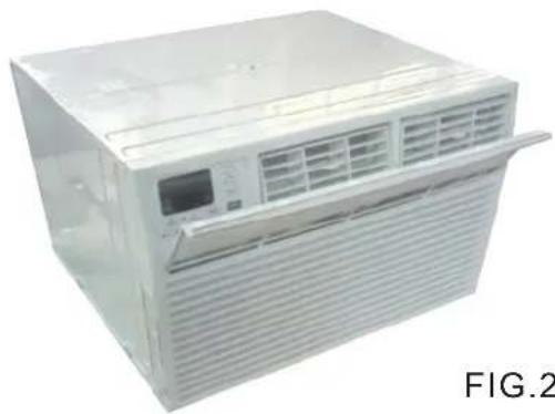
Front view of a white air conditioner unit with ventilation grilles and control panel (no visible text or symbols)INTRODUCTION
IMPORTANT SAFETY INSTRUCTION ....1
ELECTRICAL REQUIREMENTS....2
PACKINGLIST ....3
INSTALLATION & ASSEMBLY INSTRUCTIONS ....4
USING YOUR AIR CONDITIONER 8
OPERATING YOUR AIR CONDITIONER....10
CARE AND CLEANING ....11
TROUBLESHOOTING 12
IMPORTANT SAFETY INSTRUCTIONS
Before installing and using your air conditioner, please read this owner's manual carefully. Store this manual in a safe place for future reference. Your safety and the safety of others is very important to us. Please pay attention to all safety messages outlined in this owner's manual.
WARNING: To reduce the risk of fire, electrical shock or injury when using your air conditioner, follow the following basic precautions:
• Plug into a grounded 3 prong outlet.
• Do not remove the ground prong.
• Do not use a plug adapter.
• Do not use an extension cord.
• Unplug the air conditioner before servicing
- Use two or more people to move and install the air conditioner

This is a safety alert symbol.
This symbol alerts you to potential hazards that can harm you or others or even cause death.
All safety messages will directly follow the safety alert symbol and/or the words
"DANGER" or "WARNING".
! DANGER
WARNING
Failure to immediately follow these instructions may cause serious injury or even death.
All Safety messages alert you of potential hazards, how to reduce the chance of injury, and what can happen if instructions are not followed correctly.
ELECTRICAL REQUIREMENTS
WARNING

Electrical Shock Hazard
Plug into a grounded 3 prong outlet.
Do not remove the ground prong.
Do not use an adapter
Do not use an extension cord.
Failure to follow these instructions can result in death, fire, or electrical shock
The electrical ratings for your air conditioner are listed on the model and serial number label located on the front left side of the unit (when facing the front).
Specific electrical requirements are listed in the chart below. Follow the requirements below for the type of plug on the power supply cord.
Power Supply Cord
8K/10K/12K/14K Cooling 8K Cooling & Heating
10K/12K/14K Cooling & Heating
Recommended Ground Method
For your personal safety, this air conditioner must be grounded. This air conditioner is equipped with a 3 prong power supply cord with a grounded plug. To minimize the possibility of electrical shock, the cord must be plugged into a 3 prong outlet and grounded in accordance with all local codes and ordinances. If a 3 prong outlet is not available, it is the customer's responsibility to have a properly grounded 3 prong outlet installed by a qualified electrician.
It is the customer's responsibility:
• To contact a qualified electrician
- To assure that the electrical installation is adequate and in conformance with the National Electrical Code, ANSI/NFPA 70 - latest edition, and all local codes and ordinances.
Copies of the standards listed may be obtained from:
National Fire Protection Association
One Batterymarch Park
Quincy, Massachusetts 02269
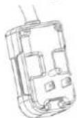
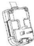
LCDI Power Cord and Plug
This air conditioner is equipped with an LCDI (Leakage Current Detection and Interruption) power cord that is required by UL. This power supply cord contains state-of-the-art electronics that sense leakage current. If the cord is damaged and leakage occurs, power will be disconnected from the unit.
The test and reset buttons on the LCDI Plug are used to check if the plug is functioning properly. To test the plug:
- Plug power cord into a grounded 3 prong outlet
- Press RESET (on some units a green light will turn on).
- Press the TEST Button, the circuit should trip and cut all power to the air conditioner (on some units a green light may turn off.
- Press the RESET button for use. You will hear a click and the A/C is ready for use.
NOTES:
• The RESET button must be engaged for proper use.
- The power supply cord must be replaced if it fails to trip when the TEST button is pressed and the unit fails to reset.
- Do not use the power supply cord as an ON/OFF switch. The power supply cord is designed as a protection device.
- A damaged power supply cord must be replaced with a new power supply cord.
- The power supply cord contains new user serviceable parts. Opening the tamper-resistant case voids all warranty and performance claims.
NOTE: Your units power cord and plug may differ from the one shown.
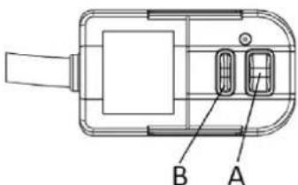
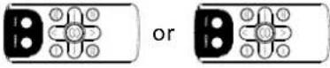
A. Reset button
B. Test button
PACKING LIST
| PAPT QUANTITYIMAGE | ||
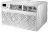 | Through-The-Wall Air Conditioner | 1 |
 | Remote Controll | 1 |
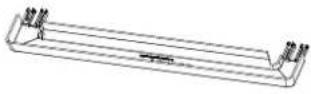 | Trim Frame 1 (Left&Right legs) | 2 |
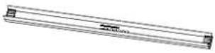 | Trim Frame 2 (Top&Bottom legs) | 2 |
 | Grille Aluminum | 1 |
 | Rear plastic net | 1 |
| [0x2y] | 1/2" Long Hex-head Screw | 4 |
 | Grouding wire with tooth washer | 1 |
| PAPTQUANTITYDimension | ||
| Seal sponge1"x3/4"x14" 2 | ||
| Seal sponge1"x3/8"x14" 2 | ||
| Seal sponge1"x3/8"x25" | 3 | |
| Seal sponge1"x1 1/2"x25" 3 | ||
| Seal sponge1"x1 1/2"x14" 2 | ||
| Seal sponge1"x1 1/2"x84" | 1 | |
| 3 3/4"x1 1/2"x4" | Seal cotton | 4 |
| Seal cotton3/4"x1 1/2"x17" 2 | ||
INSTALLATION & ASSEMBLY INSTRUCTIONS
Universal Wall-Sleeve Dimensions
- Identify the wall-sleeve brand for your preparing, from the below chart.
| Brand | Wall-sleeve Dimensions | ||
| Brand Brand | Brand | ||
| Frigidaire | 15 1/4" 25 1/2" | 16" 17 1/2" or 22" | |
| White-Westinghouse | |||
| Carrier(52 Series) | |||
| GE/Hotpoint/Amana | 15 5/8" | 26" | 16 7/8" |
| Whirlpool | 16 1/2" 25 7/8" | 17 1/8" or 23" | |
| Fedders/Emerson/Friedrich(WSE) | 16 3/4" | 27" | 16 3/4" or 19 3/4" |
| Sears/Kenmore | 16 7/8" | 25 3/4" | 18 5/8" |
| Carrier(51S Series) | |||
| Emerson/Fedders | 15 3/4" 26 3/4" | 15" | |
| Friedrich(USC) | 15 1/2" 25 7/8" | 16 3/4" | |
NOTE:
- All wall sleeves used to mount the new air conditioner must be in sound structural condition and have a rear grille that securely attaches to the sleeve, or rear flange that serves as a stop for the air conditioner.
- For new or replacement installations, a Frigidaire Sleeve Kit (EA108T) is recommended.
CAUTION:
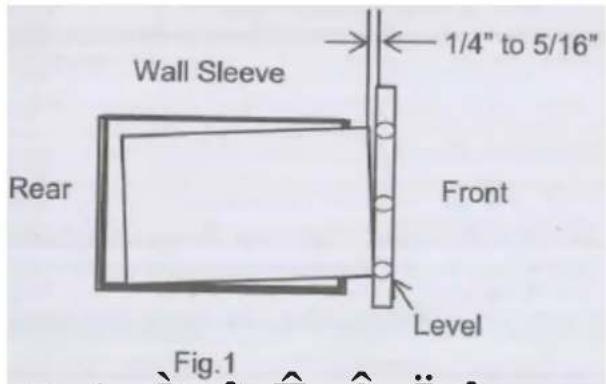
When installation is complete, replacement unit must have rearward slope as shown in Fig 1.
- Remove old Air Conditioner from wall sleeve and prepare as followings:
--- Clean interior (Do not disturb seals).
--- Check the wall sleeve to be sure it is securely fasted in the wall before installing.
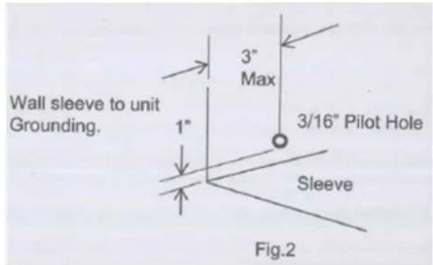
--- Repair painted surface if needed. - If the ground wire hole does not exist, drill a 3/16" pilot hole for the grounding screw through the left hand side of the sleeve, in a clear area about 3 inches max. back from the front edge as below. Pull the loose end of the ground wire out of the front of the sleeve and bend it away from the opening. This will be attached to the air conditioner once installed.
× ¢ Ô ^Fig.1 â Ê Â I î
- Install new unit into wall sleeve.
- To attach ground wire to the new unit, remove the screw from the front, left side.
- Assemble and install the trim frame.
NOTE:
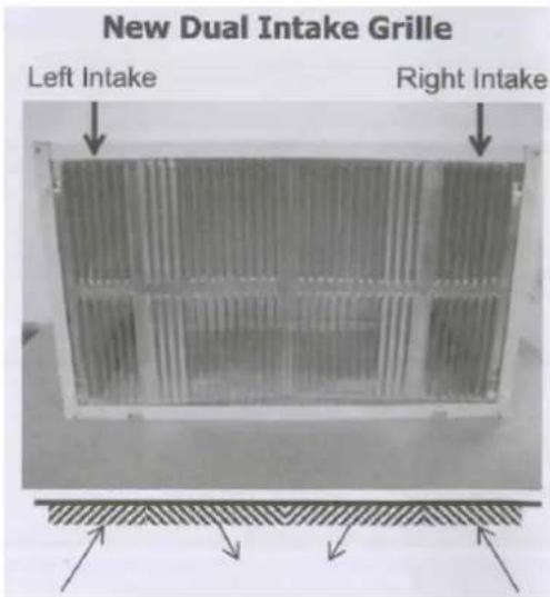
- This unit's increased performance characteristics is the result of having two rear intakes.
- It is very important that these installation instructions are followed so your unit can operate at maximum efficiency.
- If there is an existing sleeve and rear grille, please check whether the dimension is suitable or not, otherwise replace them.
Existing Frigidaire sleeves may have older single-sided intake grilles, as below pictures show.
-
These grilles should be replaced with the dual intake grille type, as shown in the pictures below.
-
Remove the existing grille and save the mounting screws.
- Place the grille included with your new air conditioner towards the inside rear of the sleeve.
- Attach the new grille by aligning the four mounting holes.
- Re-insert the self-tapping screws into the nylon retainers.
2. Grille Removal
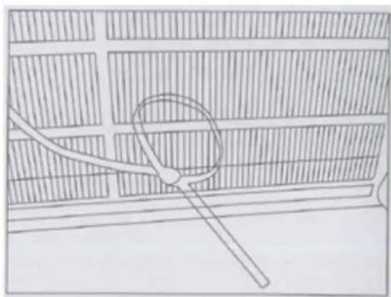
Important: Single intake grille must be removed when used with dual intake TTW unit.
Warning: When removing grille, protect it from falling by securing with a leash. This can be fastened from cord or strapping looped through the grille and secured with a knot.
While holding the grille by the leash with one hand, the retaining screws can be removed and the grille can be brought inside through the front of the sleeve.
natural_image
Simple line drawing of a magnifying glass over a grid-patterned wall (no text or symbols)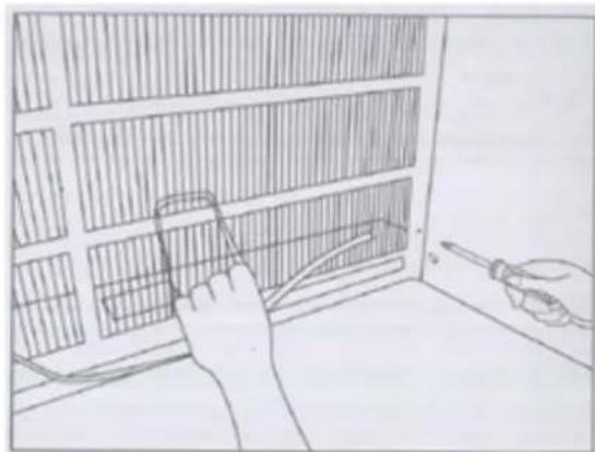
natural_image
Illustration of a hand using a tool to adjust or install a grid-patterned panel inside a room (no text or symbols visible)Direct Unit Mounting
In case where the dual intake grille cannot be mounted directly to the sleeve it is desirable to attach the grille to the back of the TTW unit to the hole predrilled in the unit.
- Attach the 2 seals(1"x3/8"x14"), as shown in Fig. 1.
- Position the grille over the rear of the unit making sure that:
a. The double set of screw holes are at the bottom.
b. The intake fins on either side are pointed away from the unit.
-
Align the top of the grille with the top of the unit. The overhang on each side is equal.
-
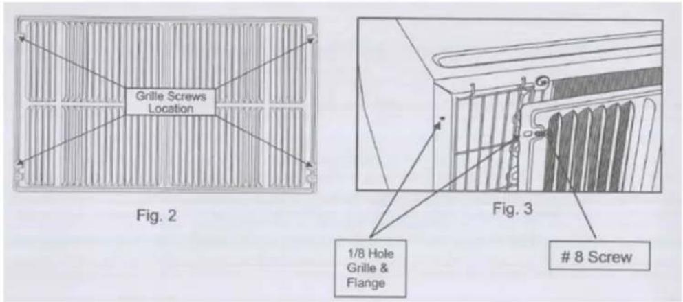
If the unit has not been predrilled (some models), carefully drill 4-1/8" holes through the grille and into the side flange of the unit approximately 1 1/2" to 2" from the top and bottom, as Fig. 2 and 3 show. (Be careful not to break the copper pipe)
-
Install 4-#8 self-tapping screws to affix the grille to the unit.
-
Insert the unit into the sleeve.
Grille to Sleeve Attachment
In case where the dual intake grille fits inside the sleeve and the grille flange overlaps the sleeve flange, direct attachment may be possible.
IMPORTANT
If the suitable grille is not used, it may lead to product damage and possible failure.
Seal Installation
-
1"x3/8"x25" long seal in the center at the top of the sleeve. Remove the back paper and press into position.
-
1"x3/8"x14" seals to the left and right sides of the sleeve.
-
Cut 1"x3/8"x25" long seals to 14" long each and attach to the vertical sections of the grille as shown.
-
1/2"x3 1/2"x1 1/2" centering blocks one on each side wall. Place in center of side wall with the tapered end facing the opening.
-
Gently slide unit into sleeve.
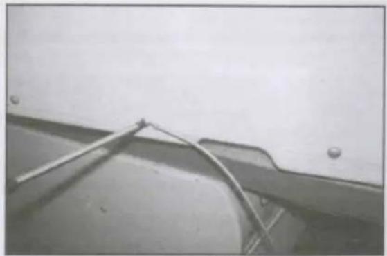
Ground Wire Installation
-
Install screw end of ground wire into inside of sleeve according to preparation instruction.
-
Before sliding unit all the way back remove second screw from left side of unit.
-
Remove plastic washer from screw.
-
Screw the other end of the ground wire into the unit as shown. Make sure the toothed washer is against the cabinet.
-
Slide unit completely to the rear.
natural_image
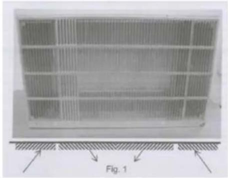
Close-up of a metal bracket with wires attached to a surface, no visible text or symbolsNon-Frigidaire Dual Intake Grille
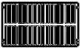
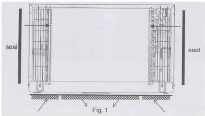
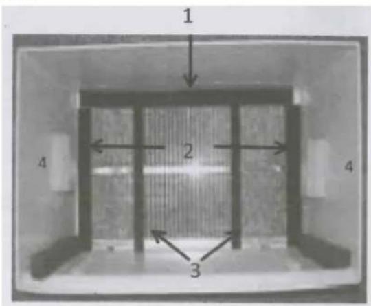
In case where the existing sleeve is a non-Frigidaire sleeve but is installed with a dual intake grille, the existing grille may be left in place. Make sure the outer 3 1/2" to 4 1/2" louvers are angled from the left and right sides of the sleeve toward the center, as Fig. 1 shows. This provides proper flow of outside air into the unit.
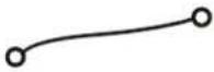
From the installation kit, apply two 1"x3/4"x14" seals along the flat metal flange of the condenser, as Fig. 2 shows.
natural_image
Diagram of a grid-patterned panel with directional arrows and label 'Fig. 1' (no readable text or symbols)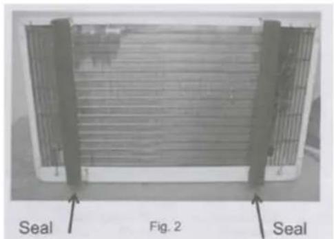
Insert the unit with the seal into the sleeve pushing it all the way to the rear, making sure the seals are against the rear grille. The seals are necessary to reduce recirculation of hot air into the intakes which would reduce system performance.
natural_image
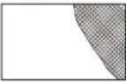
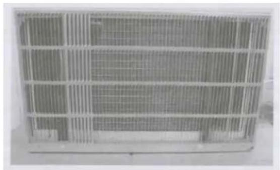
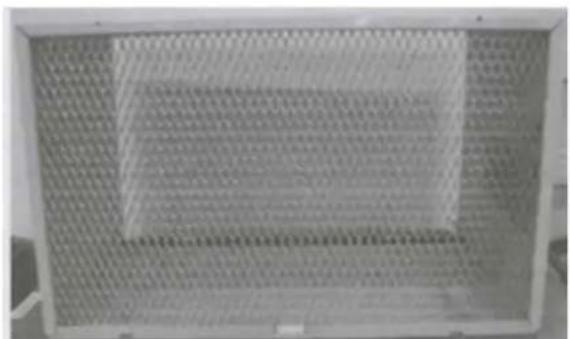
Exterior view of a rectangular metal grate with grid pattern (no text or symbols)An option is to purchase 3/4" diamond cut aluminum grille and cut it to fit inside the sleeve. Secure it with screws. Attach the dual intake grill directly to the back of the unit. Slide the entire unit into the sleeve and seal with the stuffing seal supplied with the kit.
natural_image
Metal mesh panel with grid pattern, no visible text or symbols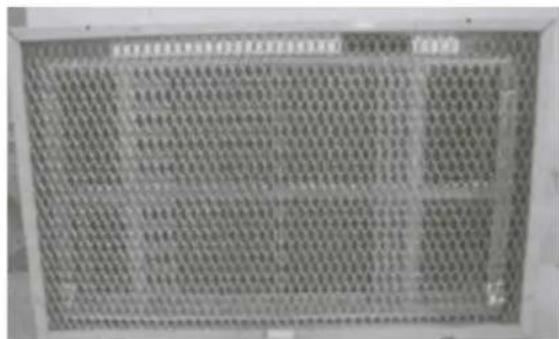
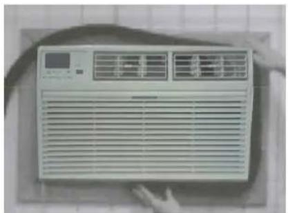
Trim Kit Installation Instructions
- Install the 1"x1"x84" long stuffer seal between the wall sleeve and the unit. A flat-bladed screwdriver or putty knife is needed.
- Assemble the trim frame by inserting the top and bottom pieces into side pieces and snapping into place.
- Pull the cord through the trim frame and slide the trim over the unit until flush with the wall.
natural_image
Front view of a white air conditioner unit with ventilation grilles and a digital display (no visible text or symbols)
natural_image
Front view of a white air conditioner unit with ventilation grilles and a digital display (no visible text or symbols)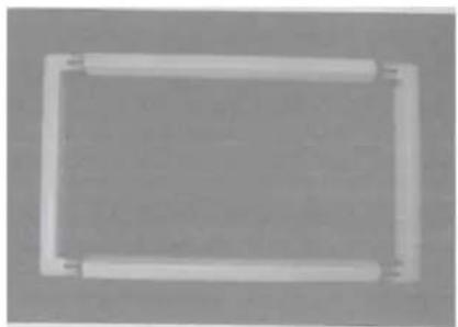
natural_image
Simple rectangular frame with rounded corners and a central hole, no text or symbols present.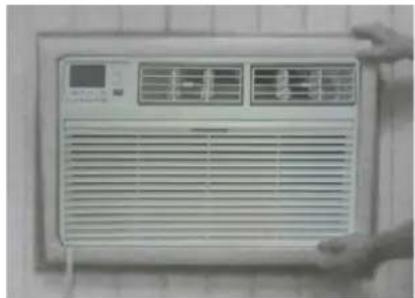
natural_image
Front view of a white air conditioner unit with ventilation grilles and a digital display (no visible text or symbols)Energy saving suggestion: In order to reach the maximum energy saving and comfortability, it is necessary to use an appropriately sized cover to provide additional insulation and air sealing when the unit is not in use during the off-using-season.
USING YOUR AIR CONDITIONER Electronic Control Panel & Remote Control
NOTE: This display always shows the room temperature in Fan Mode except when setting the Set temperature or the Timer.
For Cooling model

For Heating model
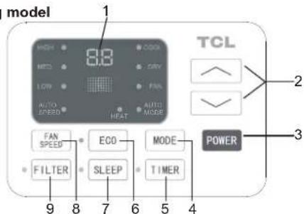
Air Conditioner Controls
Normal Operating Sounds
- You may hear a pinging noise caused by water hitting the condenser on rainy days, or when the humidity is high. This design feature helps remove moisture and improve efficiency.
- You may hear the thermostat click when the compressor cycles on and off.
- Water will collect in the base pan during rain or days of high humidity. The water may overflow and drip from the outside part of the unit.
-
The fan may run even when the compressor is not on.
-
Digital Display: Without timer setting, the operation mode is Cooling, Dry, Fan and Auto, and the set temperature will be displayed. Time will be displayed under timer setting. the
-
△ and ∨ Button: Use these buttons on the control panel and remote to increase or decrease the Set Temperature or Timer. Temperature range: 61°F\~88 or 16 \~30 °C
-
Power Button: Turn the air conditioner on and off.
- Mode Button: Press the mode button to cycle through the various modes: Cool, Dry, Fan and Auto, or Heat.
Cool Mode: The cooling function allows the air conditioner to cool the room and at the same time reduces air pressidity MODE button to activate the cooling function. To optimize the function of the air conditioner, adjust the temperature and the speed by pressing the button indicated.
Dry Mode: This function reduces the humidity of the air to make the room more comfortable. Press MODE button to set the DRY mode. An automatic function of alternating cooling cycles and air fan is activated.
Fan Mode: The conditioner works in only ventilation. Press MODE button to set the FAN mode. With pressing the FAN SPEED button the speed changes in the following sequence: Hi, Med and Lo in FAN mode. The remote control also stores the speed that was set in the previous mode of operation.
Auto Mode: In AUTO mode the unit automatically chooses the fan speed and the mode of operation (COOL,DRY or FAN). In this mode the fan speed and the temperature are set automatically according to the room temperature (tested by the temperature sensor which is incorporated in the indoor unit.).
Heat Mode: The heating function allows the air conditioner to heat the room. Press the MODE button to activate the heating function. To optimize the function of the air conditioner, adjust the temperature and the speed by pressing the button indicated.
- Timer Button: Use these buttons on the control panel and remote to set the Timer.
Timer Off: The timed stop is programmed by pressing TIMER button. Set the rest time by pressing the button or/until the rest time displayed is to your link press the TIMER button again.
Timer On: When the unit is off, press TIMER button at the first time, set the temperature with pressing the button r . 'Press TIMER button at the second time, set the rest time with pressing the button r . 'Press TIMER button at the third time, confirm the setting, then the rest time to next automatical switching-on could be read on the display of the machine.
Note: It can be set to automatically turn off or on in 0.5-24 hours. Each press of the “^” “∨” buttons will increase or decrease the timer. The Timer can be set in 0.5 hours increment below 10 hours and 1 hour increment for 10 hours or above. The SET light will turn on while setting. To cancel the set function, press the TIMER button again.
USING YOUR AIR CONDITIONER Electronic Control Panel & Remote Control
-
Eco Button: When the unit is in ECO mode, the light will turn on. In ECO mode, the unit will turn-off once the room is cooled to the user set temperature. The fan will also be off at this point. The unit will turn back on when the room temperature rises above the user set temperature. Before the compressor starts fan motor will run for a while, then it will stop for awhile, It will repeat to provide a much more comfortable feeling and save energy.
-
Sleep Button: Press the SLEEP button, The Sleep Light will be on after 10 seconds and the left lights will be off. In SLEEP mode, the air conditioner will automatically adjust the temperature and fan speed to make the room more comfortable during the night. For cooling mode, the set temperature will automatically raise by 1°F or 2°F every 30-60 minutes and at most change six times until the set temperature is 82°F. For heating mode, the set temperature will automatically decrease by 1°F or 2°F every 30-60 minutes and at most change six times until the set temperature is 75°F. And every running time depends on the set temperature.
-
Fan Speed Button: Press the FAN SPEED button to choose the fan speed options. You can choose Hi, Med, Lo or auto speed in COOL mode and choose Hi, Med, Lo in FAN mode.
-
Filter Button: When the Filter Check light is off, it isn't necessary to press the Filter Check button. When the Filter Check light is on, you can turn off the light by pressing the Filter Check button. After the fan motor works for 500 total hours, the Filter Check light will turn on to remind the user to clean the filter.
-
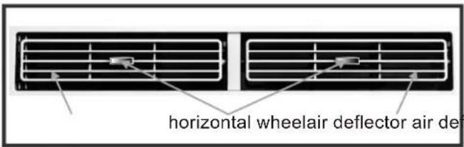
Directional Louvers: To direct the airflow, use the horizontal wheel to control the horizontal direction and the air deflector to control the vertical direction.
REMOTE CONTROL
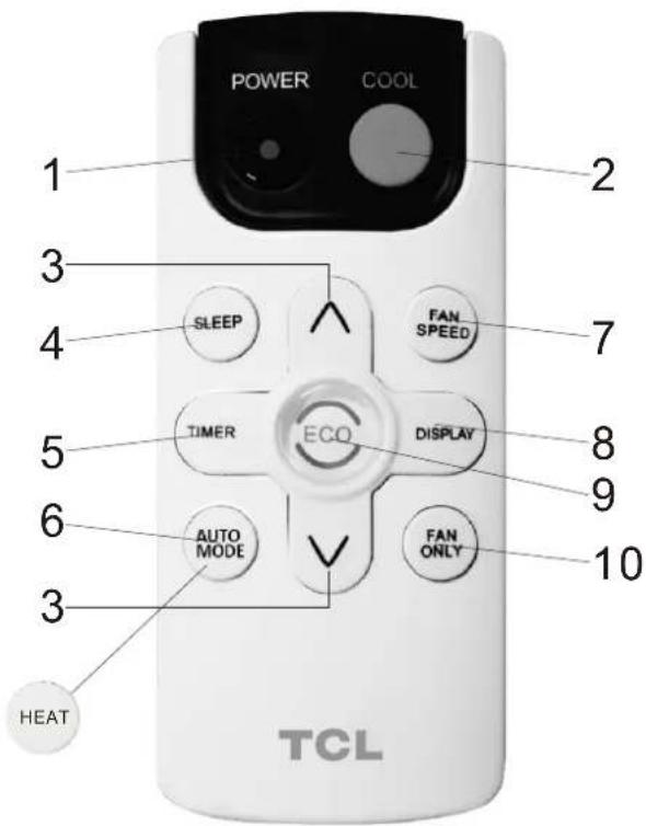
*For mark 6 button, it is AUTO MODE for cooling only, and it is HEAT for heating model.
- ____Turn the air conditioner on and off.Power:
- ____ Press the COOL button to COOL mode.Cool:
- and : Use these buttons on the control panel and remote to increase or decrease the Set Temperature or Timer. Temperature range: 61°F88 dr 16\~3°C. °C
-
Sleep: Press the SLEEP button, the Sleep Light will be on after 10 seconds all the left lights will be off. In SLEEP mode, the air-conditioner will automatically adjust the temperature and fan speed to make the room more comfortable during the night. The set temperature will automatically raise by 1°F or 2°F every 30-60 minutes and at most change six times until the set temperature is 82°F. And every running time depends on the set temperature.
-
Timer: Use these buttons on the control panel and remote to set the Timer.
Timer Off: The timed stop is programmed by pressing TIMER button. Set the rest time by pressing the button or until the rest time displayed is to your link when press the TIMER button again.
Timer On: When the unit is off, press TIMER button at the first time, set the temperature with pressing the button őr^. 'Press TIMER button at the second time, set the rest time with pressing the button őr^. 'Press TIMER button at the third time, confirm the setting, then the rest time to next automatical switching-on could be read on the display of the machine.
Note: It can be set to automatically turn off or on in 0.5-24 hours. Each press of the “^” “∨” buttons will increase or decrease the timer. The Timer can be set in 0.5 hours increment below 10 hours and 1 hour increment for 10 hours or above. The SET light will turn on while setting. To cancel the set function, press the TIMER button again.
6.a.Auto Mode: In AUTO mode the unit automatically chooses the fan speed and the mode of operation (COOL,DRY or FAN).In this mode the fan speed and the temperature are set automatically according to the room temperature (tested by the temperature sensor which is incorporated in the indoor unit.). It is for cooling only model.
b. HEAT: Press the HEAT button to HEAT mode. It is for heating model.
- Fan Speed: Press the FAN SPEED button to choose the fan speed options. You can choose Hi, Med, Lo or auto speed in COOL mode and choose Hi, Med, Lo in FAN mode.
- Display: To press the DISPLAY button, it can switch off/on all lights or LED display.
- Eco: When the unit is in ECO mode, the light will turn on. In ECO mode, the unit will turn-off once the room is cooled to the user set temperature. The fan will also be off at this point. The unit will turn back on when the room temperature rises above the user set temperature. Before the compressor stars, the fan motor will run for a while, then it will stop for a while-and will repeat to provide a much more comfortable-feeling and save energy.
- Fan Only: Press the Fan Only button to FAN ONLY mode.
CARE AND CLEANING
Clean your air conditioner to keep it looking new and to minimize dust build up.
Air Filter Cleaning
The air filter should be checked at least once every month to see if it needs cleaning. Trapped particles and dust can build up in the filter and may decrease airflow as well as cause the cooling coils to accumulate frost. To clean the air filter:
- Remove the filter by pulling down on the indents of the filter door on the front of the unit. (See FIG.21)
- Wash the filter using liquid dish soap and warm water. Rinse the filter thoroughly. Gently shake the filter to remove excess water.
- Let the filter dry completely before placing it into the air conditioner.
- If you do not wish to wash the filter, you may vacuum the filter to remove the dust and other particles.
natural_image
Exterior view of a white portable air conditioner unit with ventilation grilles and a digital display (no text or symbols visible)FIG.21
Wear and Tear
To minimize wear and tear on the air conditioner, always wait at least 3 minutes before changing modes. This will help prevent the compressor from overheating and the circuit breaker from tripping.
Cabinet Cleaning
To clean the air conditioner cabinet:
- Unplug the air conditioner to prevent shock or a fire hazard. The cabinet and front panel of the air conditioner may be dusted with an oil-free cloth or washed with a cloth dampened in a solution of warm water and mild liquid soap. Rinse thoroughly with a damp cloth and wipe dry.
- Never use harsh cleaners, wax or polish on the cabinet front.
- Be sure to wring excess water from the cloth before wiping around the controls. Excess water in or around the controls may cause damage to the air conditioner.
TROUBLESHOOTING
| PROBLEM | POSSIBLE CAUSES | SOLUTIONS |
| The Air Conditioner will not start | The air conditioner is unplugged | Make sure the air conditioner is plug is pushed completely into the outlet |
| The fuse is blown/circuit breaker is tripped. | Check the house fuse/circuit breaker box and replace the fuse or reset the breaker. | |
| Power Failure | The unit will automatically re-start when power is restored.There is a protective time delay (approx. 3 minutes) to prevent tripping of the compressor overload. For this reason, the unit may not start normal cooling for 3 minutes after it is turned back on. | |
| The current interrupter device is tripped. | Press the RESET button located on the power cord plug.If the RESET button will not stay engaged, discontinue use of the air conditioner and contact a qualified service technician. | |
| The Air Conditioner does not cool as it should | Airflow is restricted | Make sure there are no curtains, blinds, or furniture blocking the front of the air conditioner |
| The temperature control may not be set correctly. | Lower the set thermostat temperature | |
| The air filter is dirty | Clean the filter. See the Cleaning and Care Section of the manual. | |
| The room may be too warm | Please allow time for the room to cool down after turning on the air conditioner. | |
| Cold air is escaping | Check for open furnace registers and cold air returns | |
| The cooling coils are frozen | See “Air Conditioner Freezing Up” below. | |
| The Air Conditioner is freezing up | Ice blocks the air flow and stops the air conditioner from cooling the room | Set the MODE to HIGH FAN or HIGH COOL and set the thermostat to a higher temperature |
| The Remote Control is not working | The batteries are inserted incorrectlyThe batteries may be dead | Check the position of the batteries.Replace the batteries |
| Water is dripping outside | Hot and Humid weather. | This is normal |
| Water is dripping inside the room | The air conditioner is not correctly tilted outside. | For proper water drainage, make sure the air conditioner is slightly tilted downward from the front of the unit to the rear. |
| Water collects in the base pan | Moisture removed from the air is draining into the base pan. | This is normal for a short period in areas with low humidity and normal for a longer period in areas with high humidity. |
| Digital Display reads “E1”, “E2” | A sensor has failed | Contact customer service |
Modelos
TTW-08CR/UF(ES)
TTW-10CR/UF(ES)
TTW-10CR2/UF(ES)
TTW-12CR/UF(ES)
TTW-12CR2/UF(ES)
TTW-14CR2/UF
TTW-08ER/UF
TTW-10ER2/UF
TTW-12ER2/UF
TTW-14ER2/UF
natural_image
Front view of a white air conditioner unit with ventilation grilles and control panel (no visible text or symbols)INTRODUCCIÓN
Do not use an adapter
his power supply cord contains state-of-the-art electronics that sense leakage current. If the cord is damaged and leakage occurs, power will be disconnected from the unit.
natural_image
Exterior view of a rectangular metal enclosure with internal grating and mounting brackets, showing structural details (no text or symbols)natural_image
Simple line drawing of a grid-patterned structure with a circular element and diagonal lines, no text or symbols present.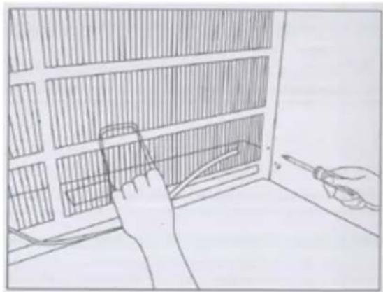
natural_image
Hand using a tool to adjust or install a grid-patterned panel inside a room (no text or symbols visible)natural_image
Close-up of a metallic pipe or cable attached to a wall, with no visible text or symbols.Rejilla de la entrada dual non-Frigidaire
natural_image
Rectangular grid pattern with horizontal bands and a labeled diagram 'Fig. 1' below (no readable text or symbols within the pattern)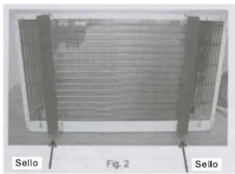
natural_image
Exterior view of a large industrial ventilation grille with grid patterns (no visible text or symbols)natural_image
Close-up of a perforated metal grate with uniform grid pattern (no text or symbols visible)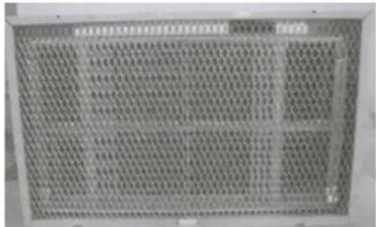
natural_image
Front view of a white air conditioner unit with ventilation grilles and a small screen (no visible text or symbols)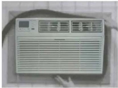
natural_image
Front view of a white air conditioner unit with ventilation grilles and a digital display (no visible text or symbols)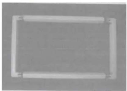
natural_image
Simple rectangular frame with rounded corners and a central horizontal bar (no text or symbols)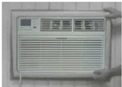
natural_image
Front view of a white air conditioner unit with ventilation grilles and a digital display (no visible text or symbols)natural_image
Exterior view of a white portable air conditioner unit (no visible text or symbols)FIG.21
Desgaste
natural_image
Front view of a white air conditioner unit with ventilation grilles and control panel (no visible text or symbols)PREAMBULE
INSTRUCTIONS IMPORTANTES DE SÉCURITÉ....1
EXIGENCES ÉLECTRIQUES ...... 2
LISTE DE COLISAGE 3
INSTRUCTIONS D'INSTALLATION ET D'ASSEMBLAGE....4
UTILISATION DE VOTRE CLIMATISEUR....8
FONCTIONNEMENT DE VOTRE CLIMATISEUR....10
SOIN ET NETTOYAGE....11
DÉPANNAGE 12
INSTRUCTIONS IMPORTANTES DE SÉCURITÉ
| Marque | Dimensiones de la pared-manga | ||
| Marque Marque | Marque | ||
| Frigidaire | 15 1/4" 25 1/2" | 16" 17 1/2" or 22" | |
| White-Westinghouse | |||
| Carrier(52 Series) | |||
| GE/Hotpoint/Amana | 15 5/8" | 26" | 16 7/8" |
| Whirlpool | 16 1/2" 25 7/8" | 17 1/8" or 23" | |
| Fedders/Emerson/Friedrich(WSE) | 16 3/4" | 27" | 16 3/4" or 19 3/4" |
| Sears/Kenmore | 16 7/8" | 25 3/4" | 18 5/8" |
| Carrier(51S Series) | |||
| Emerson/Fedders | 15 3/4" 26 3/4" | 15" | |
| Friedrich(USC) | 15 1/2" 25 7/8" | 16 3/4" | |
REMARQUE:
natural_image
Exterior view of a rectangular metal panel with vertical grating and horizontal hatching, mounted on a wall (no text or symbols visible)natural_image
Simple line drawing of a fence with a circular object and diagonal lines, no text or symbols present.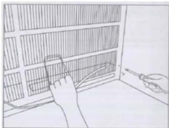
natural_image
Line drawing of a person using a tool to clean or inspect the interior wall of a window (no text or symbols)Installation de joint
natural_image
Close-up of a metal rod attached to a curved metal frame, with no visible text or symbols.natural_image
Diagram of a grid-patterned panel with labeled Fig. 1, showing no text or symbols on the panel itself.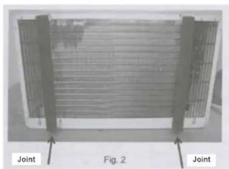
natural_image
Exterior view of a heat exchanger or cooling unit with labeled joints (no text or symbols on the device itself)natural_image
Exterior view of a rectangular metal grate with grid pattern (no text or symbols visible)natural_image
Close-up of a perforated metal panel with grid pattern, no visible text or symbols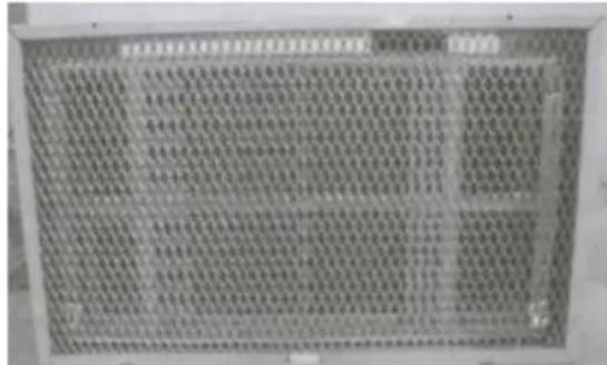
natural_image
Front view of a white air conditioner unit with ventilation grilles and a digital display (no visible text or symbols)
natural_image
Front view of a white air conditioner unit with ventilation grilles and a digital display (no visible text or symbols)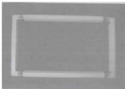
natural_image
Simple rectangular frame with rounded corners and corner connectors (no text or symbols)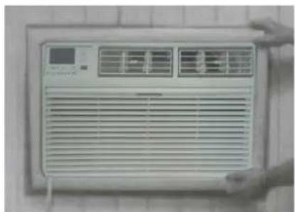
natural_image
Front view of a white air conditioner unit with ventilation grilles and a digital display (no visible text or symbols)natural_image
Exterior view of a white portable air conditioner unit (no visible text or symbols)FIG.21