Fast-Response K-1734 - Steam cleaner KOHLER - Free user manual and instructions
Find the device manual for free Fast-Response K-1734 KOHLER in PDF.

| Product Type | Steam Bath Generator |
| Brand | Kohler |
| Model | Fast-Response K-1734 |
| Power Rating | 11 kW (240 V, 46 A, 60 Hz) |
| Power Supply Required | 240 V AC, 60 Hz, dedicated 60 A circuit |
| Dimensions (W x H x D) | 44.8 cm x 50 cm x 26 cm (17-5/8" x 19-11/16" x 10-1/4") |
| Net Weight | 9.5 kg (21 lbs) |
| Maximum Steam Capacity | 9 m³ (317 ft³) |
| Water Connection | 3/8" NPT female inlet |
| Steam Outlet | 1/2" NPT |
| Relief Valve | 3/4" NPT female (supplied) |
| Maximum Distance to Steam Head | 7.62 m (25 ft) |
| Required Air Clearance | 12" (30.5 cm) around the unit |
| Automatic Fill Shut-Off | Yes |
| Operating Indicator | Green LED |
| Generator Material | Coated Steel |
| Warranty (Residential Use) | 3 years limited |
| Usage | Indoor only, installation by qualified professional |
Frequently Asked Questions - Fast-Response K-1734 KOHLER
User questions about Fast-Response K-1734 KOHLER
0 question about this device. Answer the ones you know or ask your own.
Ask a new question about this device
Download the instructions for your Steam cleaner in PDF format for free! Find your manual Fast-Response K-1734 - KOHLER and take your electronic device back in hand. On this page are published all the documents necessary for the use of your device. Fast-Response K-1734 by KOHLER.
USER MANUAL Fast-Response K-1734 KOHLER
K-1652, K-1657, K-1658,
K-1659, K-1695, K-1708,
K-1733, K-1734
Mproduct numbers are for Mexico (i.e. K-12345M)
Plus:
- Drain/spill pan
- 1/2" copper tubing
- Assorted copper fittings; 3/8", 1/2" and 3/4" copper NPT unions
• Wire Cutters or Wire Strippers
• Conventional woodworking tools and materials
• 45 and 90 degree elbows
• Support Blocks (heat resistant)

Sealant Tape

Solder
Propane Torch
BeforeYouBegin
IMPORTANT!Whenusingthisunit,basicprecautionsshouldalwaysbefollowed.
DANGER: Risk of electrocution. Disconnect the electricity to the working area at the main breaker panel before performing these installation steps.
WARNING: Riskofpersonalinjury. If you become uncomfortable while taking a steam bath, you should power off the unit. Cool off with the shower, open the door, or exit the unit.
WARNING: Riskofallergicreaction. Before adding any oils, aromatic therapies, or skin care products to the aromatherapy well, make sure they will not cause an allergic reaction to the user.
WARNING: Riskofpersonalinjury. This steam bath may not be suitable for use if you are pregnant, have a heart condition, have high blood pressure, have circulatory problems, are under the influence of alcohol, are taking drugs or are under the care of a physician. A steam bath can put undue stress on the body, as does any hot bath, shower, or sauna.
WARNING: Riskofpersonalinjury. DONOT consume alcoholic beverages or take medications/drugs prior to or when using the steam bath. Alcohol and drugs affect mental judgement and inhibit bodily functions such as heartbeat and respiration, resulting in potentially dangerous effects.
WARNING: Riskofinjurytochildren. Do not allow children to use this unit unless they are closely supervised at all times. The steam generator is not designed to be used by children.
WARNING:Riskofpersonalinjury.Do not plumb a trap in the steam line or plumb the pressure relief valve into the steam line. Plumbing the pressure relief valve into the steam line can be hazardous if the steam outlet is capped.
WARNING: Riskofpersonalinjuryorpropertydamage. Avoid coming in contact with the water tank and/or steam discharge line while the generator is operating or shortly after shutdown. Wear eye protection and protective clothing when servicing the steam generator. The steam generator operates at high temperatures.
NOTICE: Use this unit only for its intended use as specified in this manual. DO NOT use attachments not recommended by Kohler Co.
NOTICE: Do not apply excessive heat to the generator connections when you solder connections. Do not apply flux or acids directly to the generator, as damage to the seals, plastic components, and trim finish may result. Do not apply petroleum-based lubricants to the generator components, as damage may result.
BeforeYouBegin(cont.)
☐ Inspect the product for any damage. Contact the KOHLER Customer Care Center using the information on the back of this guide.
☐ Follow all local plumbing and electrical codes. All electrical work should be done by a qualified electrician.
□ Disconnect all power before making any electrical connections.
☐ Kohler Co. reserves the right to make revisions in the design of products without notice, as specified in the Price Book.

1. DeterminetheLayout

WARNING: Risk of property damage. Allow a minimum of 12" (30.5 cm) of air space around the steam generator at all times. This provides an area for the heat generated by the unit to dissipate.
NOTICE: The steam generator will perform best when installed as close as possible to the steam head. The unit should be installed within 25' (7.62 m) of the steam head.
NOTICE: For optimum performance install the steam generator below the level of the steam head.
NOTE: When possible, use 45 degree elbows. Performance will be increased when 45 degree elbows are used.
NOTE: The "Recommended Layout Options" sections include information specific to Kohler bath and shower products. Refer to those sections for additional layout information.
☐ Determine the location of the steam generator. Allow for a 12" (30.5 cm) air gap on all sides of the generator. Allow for a drain pan.
☐ Choose a drain pan appropriate for your installation. The drain pan is not supplied.
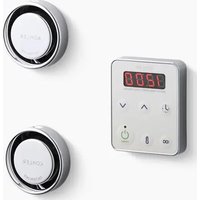
2. DeterminetheLocationoftheSteamHardware

WARNING: Riskofpersonalinjury. Do not install the Steam Control User Interface outside the steam enclosure. The User Interface must be installed within the enclosure to allow the sensors to regulate the temperature and control the flow of steam. Refer to the Installation Guide for the Steam Control Kit.

WARNING: Risk of scalding. Do not block the steam head or locate it near a seat or bench, as the steam head is hot during operation and may scald the user if touched.
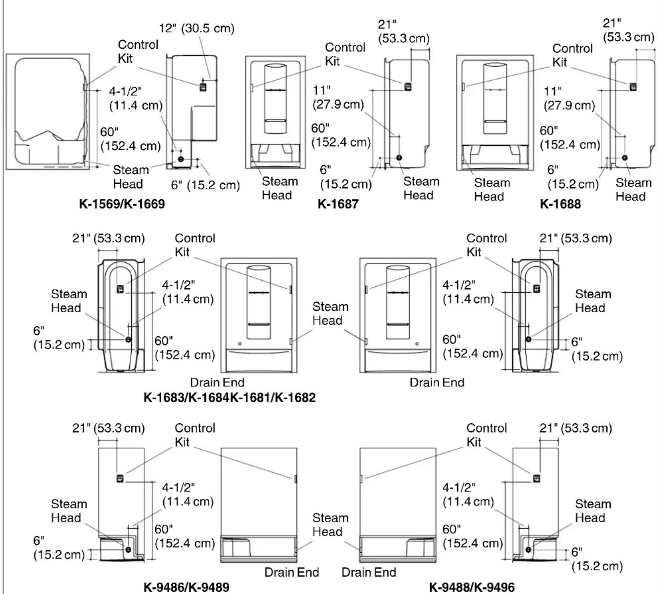
Modules;SteamHeadandControlLocation
NOTE: All dimensions should be taken from the inside of the shower.
IMPORTANT! Do not install the control directly above or in-line with the steam head.
☐ Review the layout options as an aid to determine the location for the components of the steam system.
DeterminetheLocationoftheSteamHardware(cont.)
- Identify the model number of the shower module as shown in the illustration.
☐ Determine the location of the steam head and steam control for the module as shown in the modules illustration.
☐ Ensure clearance between the steam line and any surrounding surfaces.
□ Refer to the Steam Control Kit Installation Instructions for more information.
ForCustomShowerApplications

WARNING: Riskofpersonalinjury. Do not install the Steam Control User Interface outside the steam enclosure. The User Interface must be installed within the enclosure to allow the sensors to regulate the temperature and control the flow of steam. Refer to the Installation Guide for the Steam Control Kit.
NOTE: All dimensions should be taken from the inside of the shower.
IMPORTANT! Do not install the steam control directly above or in-line with the steam head.
☐ It is recommended to locate the steam head and the steam control on the same wall as the plumbing controls.
- Locate the steam head 6" (15.2 cm) above the shower floor and 4 1/2" (11.4 cm) from the threshold.
☐ Locate the steam control 60" (152.4 cm) above the floor of the shower. Refer to the Steam Control Kit Installation Instructions for more dimensional and installation information.
☐ Make sure there is adequate clearance between the steam line and any surrounding surfaces.
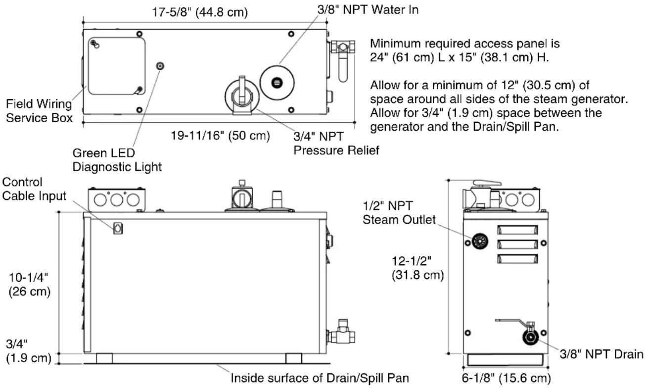
Minimum required access panel is 24" (61 cm) L x 15" (38.1 cm) H.
Allow for a minimum of 12" (30.5 cm) of space around all sides of the steam generator. Allow for 3/4" (1.9 cm) space between the generator and the Drain/Spill Pan.
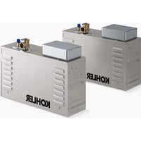
3. DeterminetheLocationoftheSteamGenerator
IMPORTANT! The minimum required access panel is 24" (61 cm) L x 15" (38.1 cm) H. Allow for a minimum 12" (30.5 cm) space around all sides of the steam generator. Allow for 3/4" (1.9 cm) space between the generator and the drain pan.
☐ Ensure clearance between the steam line and any surrounding surfaces.
□ Allow for access to the steam generator after installation.
☐ Allow for a 12"(30.5 cm) air gap on all sides of the generator.
□ Allow for a drain or spill pan.
☐ For optimum performance, install the steam generator below the level of the steam head and as close as possible to the steam head. The steam generator should be installed within 25 ft (7.62 m) of the steam head in a dry, well-ventilated area
- Install the Electrical Supply
| ModelK-1652,K-1 | 695K-1657,K-1708K-1658,K-1733K-1659,K-1734 | |||
| OrderingInformation | ||||
| RequiredElectricalService | ||||
| Generator - Dedicated Circuit Required | 5 kW, 240 V 40 A, 50/60 Hz | 7 kW, 240 V, 50 A, 50/60 Hz | 9 kW, 240 V, 60 A, 50/60 Hz | 11 kW, 240 V, 60 A, 50/60 Hz |
| ProductInformation | ||||
| Weight | 21 lbs (9.5 kg) | 21 lbs (9.5 kg) | 21 lbs (9.5 kg) | 21 lbs (9.5 kg) |
| Electrical Rating | 240 V, 27 A, 60 Hz | 240 V, 36 A, 60 Hz | 240 V, 45 A, 60 Hz | 240 V, 46 A, 60 Hz |
| Installthe Electrical Supply(cont.) | ||||
| Water Supply 3/8" copper line (3/8"NPT female thread) | 3/8" copper line (3/8"NPT female thread) | 3/8" copper line (3/8"NPT female thread) | 3/8" copper line (3/8"NPT female thread) | 3/8" copper line (3/8"NPT female thread) |
| Steam Line 1/2" copper line (1/2"NPT thread) | 1/2" copper line (1/2"NPT thread) | 1/2" copper line (1/2"NPT thread) | 1/2" copper line (1/2"NPT thread) | 1/2" copper line (1/2"NPT thread) |
| Pressure Relief Valve (supplied) | 3/4"NPT female thread | 3/4"NPT female thread | 3/4"NPT female thread | 3/4"NPT female thread |
| Drain Line Valve | 3/8" copper line, (3/8"NPT female thread) | 3/8" copper line, (3/8"NPT female thread) | 3/8" copper line, (3/8"NPT female thread) | 3/8" copper line, (3/8"NPT female thread) |
| SizingTheSteamRoom | ||||
| 56 cu ft (1.6 cu m) 112 cu ft (3.2 cu m) 240 cu ft (6.8 cu m) 317 cu ft (9 cu m) | ||||
| DANGER: Risk of electrocution. Disconnect the electricity to the working area at the main breaker panel before performing these installation steps.Follow all local electrical codes. All electrical work should be done by a qualified electrician.Review the illustration showing specific Steam Generator Installation Requirements for your Steam Generator.Install the appropriate electrical supply. | ||||
Maintain a 12" (30.5 cm) space around the unit.
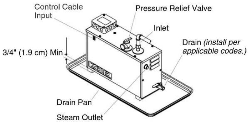
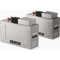
5. InstalltheSteamGenerator

WARNING: Risk of property damage. Allow a minimum of 12" (30.5 cm) of air space around the steam generator at all times. This provides an area for the heat generated by the unit to dissipate.
NOTICE: For optimum performance, install the steam generator as close as possible to the steam head. The steam generator must be installed within 25' (7.62 m) of the steam head.
□ Install the desired drain pan at the steam generator location.
IMPORTANT! The support blocks should be constructed of heat resistant material.
☐ Position support blocks so the steam generator will have 3/4" (1.9 cm) of clearance from the drain pan.
☐ Position the steam generator on the support blocks.
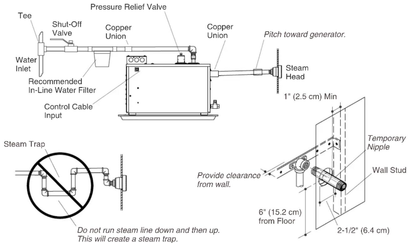
6. Install the Water Supply Line and Steam Line

WARNING: Riskofpersonalinjuryorpropertydamage. Do not plumb the pressure relief valve into the steam line. Plumbing the pressure relief valve into the steam line can create a hazard if the steam line is blocked or obstructed.

WARNING: Risk of scalding. Do not plumb a trap, shut-off valve, or pressure relief valve into the steam line. Plumbing the pressure relief valve into the steam line can be hazardous, if the steam outlet is capped.

WARNING: Riskofpersonalinjuryorpropertydamage. Do not direct the pressure relief valve to the enclosure. In the event the pressure relief valve activates, the hot water may spray causing burns to the user and/or damage the enclosure. Therefore, the pressure relief valve should be directed to an area where damage will not occur from contact with hot water and should conform to national and local plumbing codes.
InstalltheWaterSupplyLinetotheGenerator
NOTE: For all NPT threaded connections, use pipe tape or pipe sealant. Do not overtighten the fittings.
- Connect to an existing cold water line, and run a 3/8" cold water line to a shut-off valve before the in-line water filter.
Before final connection to the steam generator, flush out the water supply line into a large pail. This removes any debris, silt, sand, or other material that may be in the line.
☐ Install 3/8" copper tubing with a union fitting between the in-line water filter and the water inlet to the steam generator.
□ Connect the water supply line to the steam generator.
☐ Make sure that the water drain valve on the generator is closed.
InstalltheWaterSupplyLineandSteamLine(cont.)
- Fill the steam generator with water and check for leaks.
NOTICE: Steam generators are equipped with an automatic shut-off. The water will stop after the unit is full. If the water flows out of the steam outlet shut off the water and consult the "Troubleshooting Guide" or contact the Customer Care Center using the number located on the back of this document.
☐ If the water supply line exceeds 10' (3 m) or is exposed to cold areas, insulate the piping with appropriate insulation.
InstalltheSteamLine

WARNING: Riskofscalding. Do not locate the steam head near a seat or bench or scalding may occur upon contact with the steam head.
NOTICE: Never run the steam line down, then up. Running the steam line down and then up will create a steam trap, blocking the flow of steam. The steam line should run up to the steam head from the steam generator, at a pitch of 3/8" (1 cm) to 1/2" (1.3 cm) per 12" (30.5 cm) of pipe.
NOTICE: Provide clearance between the back wall and the elbow leading into the steam housing. The elbow must not contact any wall material.
NOTICE: Provide clearance between the steam line and surrounding surfaces.
NOTICE: Do not apply excessive heat to the generator connections when you solder connections. Do not apply flux or acids directly to the steam generator, as damage to the seals, plastic components, and trim finish may result. Do not apply petroleum-based lubricants to the steam generator components, as damage may result.
NOTE: For all the threaded connections, use thread sealant tape or pipe sealant. Do not overtighten the fittings.
NOTE: Use 1/2" copper tube for the steam line.
NOTE: Always install a union fitting as close to the steam generator as possible.
☐ Add blocking behind the desired steam head location.
☐ Install and secure a 1/2"NPT elbow to the blocking directly behind the desired steam head location.
☐ Cut a hole through the wall material to accept a temporary 1/2" copper tube nipple.
☐ Add a temporary 1/2" copper tube nipple.
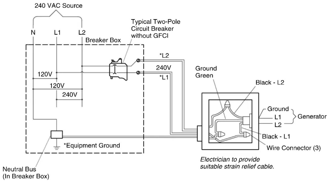
7. ConnectthePower

DANGER: Riskofelectrocution. Disconnect all power before performing these installation steps.
NOTICE: All electrical work should be done by a qualified electrician.
NOTICE: All electrical wiring must be done in accordance with local codes.
NOTICE: Each steam generator requires a dedicated circuit.
ConnectthePower
☐ Turn off all electricity to the working area at the main circuit breaker panel.
☐ Connect 240 VAC electrical line to the wires labeled "L1", "L2", and the green (ground) wire coming out of the steam generator field service box located on top of the steam generator.
- Confirm the ground connection has been made in the field service box.
□ Close the field service box.
□ Turn on the main power.
☐ The function light should display a green light. If the function light is not green, consult the "Troubleshooting Guide" or contact the Customer Care Center using the number located on the back of this document.
8. Complethethel Installation
☐ Install the steam housing and steam head following the instructions packed with the Steam Control Kit.
☐ Install the steam control following the instructions packed with the Steam Control Kit.
Completethel Installation(cont.)
☐ To operate the steam control, follow the operation instructions provided with the Steam Control Kit.
Warranty
KOHLERSteamGenerator THREE-YEARLIMITEDWARRANTY
Kohler steam generator units manufactured after September 15, 2001, are warranted to the original consumer purchaser to be free of manufacturing defects in material and workmanship during normal residential usage for three (3) years from the date of installation. This warranty only applies to KOHLER steam generator units installed in the United States of America, Canada or Mexico ("North America").
If a defect is found in normal residential usage, Kohler Co. will, at its election, repair or replace the unit, or make appropriate adjustment. Damage caused by accident, misuse or abuse is not covered by this warranty. Proof of purchase (original sales receipt) must be provided to Kohler Co. with all warranty claims. Kohler Co. is not responsible for labor charges, removal charges, installation, or other consequential costs. In no event shall the liability of Kohler Co. exceed the purchase price of the unit.
If this unit is used commercially or installed outside of North America, Kohler Co. warrants the unit to be free from defects in material and workmanship for one (1) year from the date of installation with all other terms of this warranty applying except duration.
To obtain warranty service contact Kohler Co., either through your Dealer, Plumbing Contractor, Home Center or E-tailer or by writing Kohler Co., Attn: Customer Care Center, 444 Highland Drive, Kohler, WI 53044, USA, or by calling 1-800-4-KOHLER (1-800-456-4537) from within the USA and Canada, and 001-800-456-4537 from within Mexico, or visit www.kohler.com within the USA, www.ca.kohler.com from within Canada, or www.mx.kohler.com in Mexico.
KOHLERCO.AND/ORSELLERAREPROVIDINGTHESEWARRANTIESINLIEUOFALLOTHER WARRANTIES,EXPRESSEDORIMPLIED,INCLUDINGBUTNOTLIMITEDTOTHEIMPLIED WARRANTIESOFMERCHANTABILITYANDFITNESSFORAPARTICULARPURPOSE.KOHLERCO. AND/ORSELLERDISCLAIMANYLIABILITYFORSPECIAL,INCIDENTALORCONSEQUENTIAL DAMAGES.Somestates/provincesdonotallowlimitationsonhowlonganimpliedwarrantylasts,orthe exclusionorlimitationofspecial,incidentalorconsequentialdamages,sotheselimitationsandexclusions maynotapplytoyou.Thiswarrantygivesyouspecificlegalrights.Youmayalsohaveotherrights,which varyfromstate/providencetostate/providence.
ThisisKohlerCo.'sexclusivewrittenwarranty.
TroubleshootingGuide

CAUTION: Troubleshooting steps involving internal wires or electrical components should be performed by a qualified electrician.
NOTE: This troubleshooting only applies to the steam generator. For issues involving the steam control, consult the troubleshooting guide provided with the Steam Control Kit documentation.
The troubleshooting guide is for general aid only. For service and installation issues and concerns, contact the Customer Care Center using the information on the back of this guide.
| TroubleshootingGuide(cont.) | ||
| SymptomsProbableCausesRecommendedAction | ||
| 1.The green LED light is not on. | A. No electrical power at generator. | A1. Reset the power at the breaker. |
| A2.Have a qualified electrician verify that 240 V of power is present at the generator. | ||
| B.Circuit breaker is in the "Off" position. | B.Turn on the power at the breaker. | |
| C.Circuit breaker is not the correct size. | C.Verify the circuit breaker is sized appropriately. If it is the wrong size, replace it. | |
| D.Electrical connection in the field service box on the generator is loose. | D.Turn off all electrical power to the generator. Have a qualified electrician open the field service box and check all connections. Have a qualified electrician repair any poor connections. | |
| 2.There is a continuous flow of water from the steam head. Water flow during the power clean cycle is normal. | A.Components internal to the generator are not functioning properly. | A1.Shut off the water supply and drain the water from the generator. Close the drain valve. |
| A2.Partially open the supply shut-off valve a small amount. | ||
| A3.Allow the water to gradually fill the tank inside the generator (may take several minutes). If the water continues to flow from the steam head, A1. | ||
| A4.Fully open the water supply shut-off valve. | ||
| A5.Onmodelswithpowerclean optiononly,if water continues to flow from the steam head, run the power clean cycle. | ||
| A6.If water continues to flow from the steam head, contact the Customer Care Center using the information on the back of this guide. | ||
| B.The water supply is incorrectly connected to the generator. | B.Review the installation guide and if necessary reconnect the water supply to the proper location. | |
natural_image
Illustration of two different types of tools: a screwdriver and an adjustable wrench (no text or symbols present)