Invigoration K-32334 - Steam cleaner KOHLER - Free user manual and instructions
Find the device manual for free Invigoration K-32334 KOHLER in PDF.

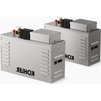
| Product type | Steam generator (steam cleaner) |
| Brand | Kohler |
| Model | Invigoration K-32334 |
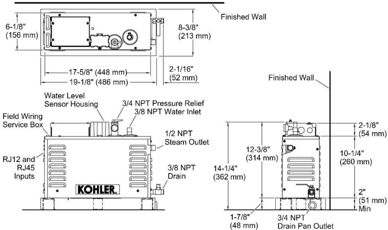
| Dimensions (H x W x D) | 448 x 362 x 156 mm |
| Weight | 13.2 kg (single version) |
| Electrical supply | 240 V, 40-60 A, 50/60 Hz (depending on power) |
| Available power | 5 kW, 7 kW, 9 kW, 11 kW |
| Maximum steam chamber volume | Up to 317 ft³ (9.0 m³) for 11 kW |
| Maximum incoming water pressure | 70 psi (483 kPa) |
| Water line | Copper 1/2 in |
| Steam line | Copper 1/2 in |
| Steam outlet connection | NPT 1/2 |
| Water inlet connection | NPT 3/8 |
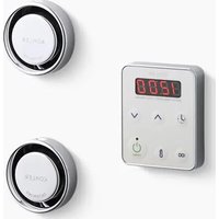
| Special features | PowerClean (automatic purge), quick-response heating, digital display |
| Safety | Pressure relief valve, hyperthermia protection, automatic shut-off |
| Warranty | 3-year limited |
| Customer service | 1-800-4KOHLER (United States/Canada) |
| Replacement parts | kohler.com/serviceparts |
| Care and cleaning | kohler.com/clean |
| Compliance | FCC Part 15 Class B, ICES-003 |
Frequently Asked Questions - Invigoration K-32334 KOHLER
User questions about Invigoration K-32334 KOHLER
0 question about this device. Answer the ones you know or ask your own.
Ask a new question about this device
Download the instructions for your Steam cleaner in PDF format for free! Find your manual Invigoration K-32334 - KOHLER and take your electronic device back in hand. On this page are published all the documents necessary for the use of your device. Invigoration K-32334 by KOHLER.
USER MANUAL Invigoration K-32334 KOHLER
Installation Instructions
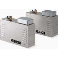
Steam Generator (5 kW - 11 kW)
Record your model number:
Need help? Contact our Customer Care Center.
- USA/Canada: 1-800-4KOHLER (1-800-456-4537) Mexico: 001-800-456-4537
Hours of Operation: Monday-Friday 8:00 AM -5:00 PM (CT)
Languages Spoken: English, Spanish, and translation services are available.
• Service parts: kohler.com/serviceparts
• Care and cleaning: kohler.com/clean
• Patents: kohlercompany.com/patents
Warranty
This product is covered under the KOHLER® Steam Generator Three-Year Limited Warranty, found at kohler.com/warranty. For a hardcopy of warranty terms, contact the Customer Care Center.
Required Tools and Materials
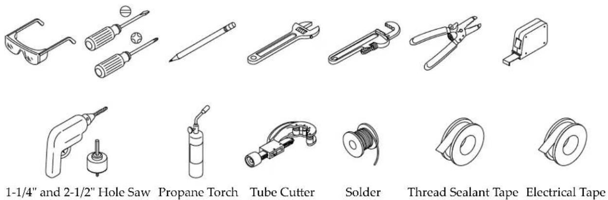
Wire Clamps (qty 3)
Additional Required Tools and Materials:
- Drain or spill pan
- 1/2" copper tubing
• Assorted copper fittings - Conventional woodworking tools and materials
- 45^ and 90^ elbows
• Support Blocks (heat resistant)
READ AND FOLLOW ALL INSTRUCTIONS.
When installing and using this electrical equipment, basic safety precautions should always be followed, including the following:

WARNING: Risk of explosion. For dual steam generator installations, do not interconnect steam outlets. A separate steam line must be provided for each steam outlet.

WARNING: Risk of electrocution. Disconnect all power before performing these installation steps.

WARNING: Risk of personal injury.
- The wet surfaces of steam enclosures may be slippery. Use care when entering or leaving.
- The steam head is hot. Do not touch the steam head and avoid the steam near the steam head.
- Prolonged use of the steam system can excessively raise the internal human body temperature and impair the body's ability to regulate its internal temperature (hyperthermia). Limit your use of steam to 10 - 15 minutes until you are certain of your body's reaction.
- Excessive temperatures have a high potential for causing fetal damage during the early months of pregnancy. Pregnant or possibly pregnant women should consult a physician regarding the correct exposure.
- Obese persons and persons with a history of heart disease, low or high blood pressure, circulatory system problems, or diabetes should consult a physician before using a steambath.
- Persons using medication should consult a physician before using a steambath since some medications may induce drowsiness while other medications may affect heart rate, blood pressure, and circulation.

WARNING: The use of alcohol, drugs, or medication can greatly increase the risk of fatal hyperthermia.
Prolonged immersion in hot water may induce hyperthermia. Hyperthermia occurs when the internal temperature of the body reaches a level several degrees above the normal body temperature of 98.6^ F ( 37^ C). The symptoms of hyperthermia include an increase in the internal temperature of the body, dizziness, lethargy, drowsiness, and fainting. The effects of hyperthermia include: (a) failure to perceive heat, (b) failure to recognize the need to exit the bath, (c) unawareness of impending hazard, (d) fetal damage in pregnant women, (e) physical inability to exit the bath, and (f) unconsciousness resulting in the danger of drowning.

WARNING: Risk of personal injury. If you become uncomfortable while taking a steambath, you should turn OFF the unit. Cool off with the shower, open the door, or exit the unit.

WARNING: Risk of allergic reaction. Before adding any oils, aromatic therapies, or skin care products to the aromatherapy well, verify that they will not cause an allergic reaction to the user.

CAUTION: Risk of injury. To reduce the risk of injury, do not permit children to use this product unless they are closely supervised at all times.

CAUTION: Risk of personal injury. Do not plumb a trapway in the steam line or plumb the pressure relief valve into the steam line. Plumbing the pressure relief valve into the steam line can be hazardous if the steam outlet is capped.

CAUTION: Risk of personal injury or property damage. Avoid coming in contact with the water tank and/or steam discharge line while the steam generator is operating or shortly after shutdown. Wear eye protection and protective clothing when servicing the steam generator. The steam generator operates at high temperatures.

CAUTION: Do not use for space heating purposes.
IMPORTANT! Recommended feedwater quality should be: Hardness - less than 60 ppm (3.5 gpg); Total Alkalinity - greater than 150 ppm (8.8 gpg). Calcium scale buildup from hard water can prevent proper operation of the steam generator and may cause premature failure. To verify proper operation, the feedwater supply should be tested before
operating the steam generator. If feedwater quality is not within the specified limit, contact a reputable water treatment company for treatment options.
IMPORTANT! Maximum inlet water pressure is not to exceed 70 psi (483 kPa).
NOTICE: Use this unit only for its intended use as specified in this manual. DO NOT use attachments that are not recommended by Kohler Co.
NOTE: Do not alter or modify this product. Modifications may result in inoperation or a hazardous installation.
NOTICE: Do not apply excessive heat to the steam generator connections when you solder connections. Do not apply flux or acids directly to the steam generator, as damage to the seals, plastic components, and trim finish may result. Do not apply petroleum-based lubricants to the steam generator components, as damage may result.
Before You Begin
IMPORTANT! The minimum required size for the service access panel is 24" (610 mm) L x 15" (381 mm) H.
IMPORTANT! All electrical work should be done by a qualified electrician.
IMPORTANT! Install the steam generator in a well ventilated and temperature-controlled location.
IMPORTANT! The steam generator is compatible with installations that require a water-hammer arrestor or pressure-reducing valve to achieve optimal performance.
NOTE: To verify proper steam head installation, refer to the steam head Installation Instructions prior to installing the steam generator.
NOTE: To verify proper control installation, refer to the control Installation Instructions prior to installing the steam generator.
NOTE: The instructions in this installation guide cover both single and dual steam generator installations.
Inspect the product for any shipping damage. Do not install the unit if there is damage. Contact Kohler Co. Customer Care Center using the information on the back of this guide.
Connect the steam generator to water supply lines that meet all applicable plumbing codes.
Follow all local plumbing, building, and electrical codes.
READ AND FOLLOW ALL INSTRUCTIONS
SAVE THESE INSTRUCTIONS

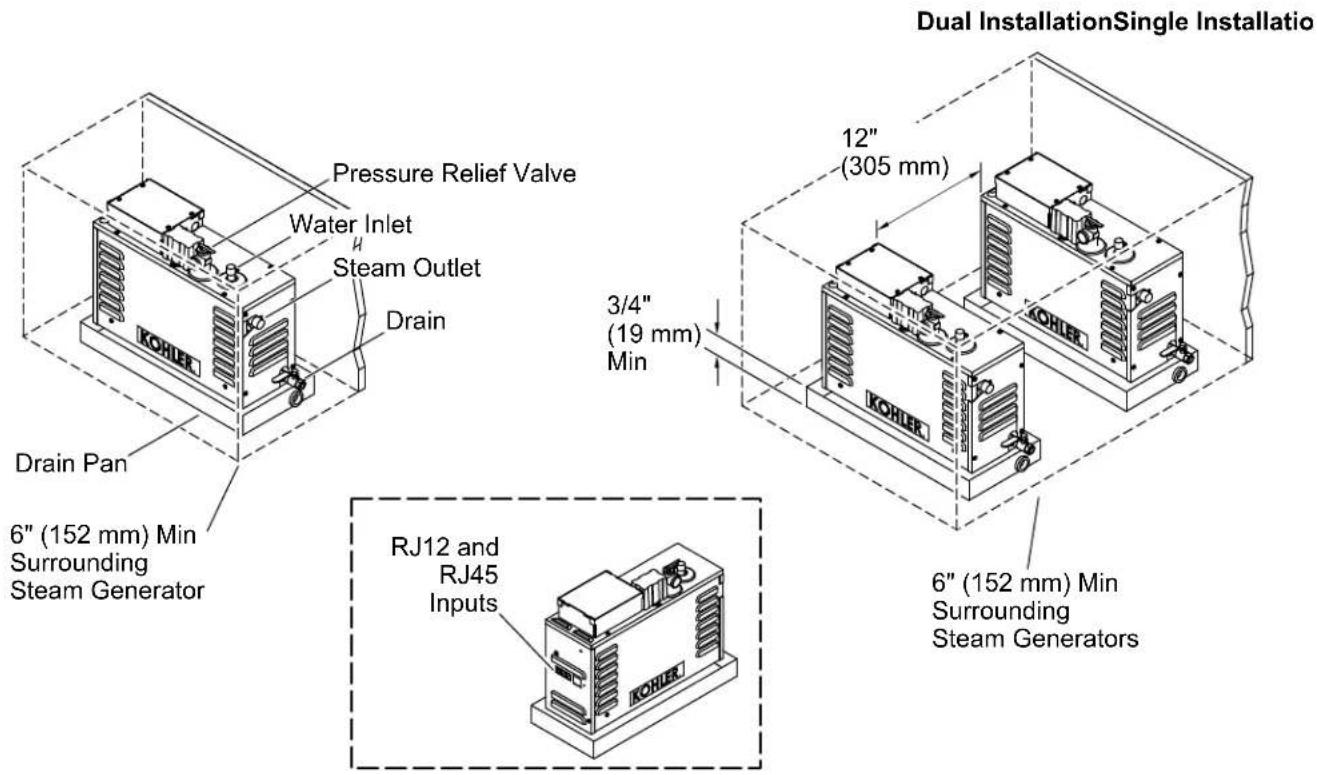
WARNING: Risk of property damage. There must be a minimum of 6" (152 mm) of air space surrounding the steam generator on at least three sides. This provides an area for the heat generated by the unit to dissipate.
IMPORTANT! The minimum required size for the service access panel is 24" (610 mm) L x 15" (381 mm) H.
IMPORTANT! Connect only copper piping to the 1/2 NPT Steam Outlet. No other material is acceptable.
NOTICE: For optimum performance, install the steam generator as close as possible to the steam head. The steam generator must be installed within 25' (7.62 m) of the steam head.
NOTE: Use the dimensions in the diagram above for reference when determining the placement and clearance for the steam generator.
NOTE: Unions are supplied for the steam outlet and water inlet for connection to a 1/2" copper pipe.
Allow for a drain or spill pan. KOHLER® drain pan shown (sold separately).
1. Determine the System Layout
Single Installation

WARNING: Risk of property damage. There must be a minimum of 6" (152 mm) of air space surrounding the steam generator on at least three sides. This provides an area for the heat generated by the unit to dissipate.

WARNING: Risk of explosion. For dual steam generator installations, do not interconnect steam outlets. A separate steam line must be provided for each steam outlet.
IMPORTANT! The minimum required size for the service access panel is 24" (610 mm) L x 15" (381 mm) H.
IMPORTANT! This steam generator must only be installed in the upright position as shown. The pressure relief valve location must be on top.
IMPORTANT! Install the steam generator in a well ventilated and temperature-controlled location.
IMPORTANT! Do not install the steam generator outdoors, inside the steam room, or in areas where flammable materials may be stored.
IMPORTANT! If this steam generator will be installed in a location that is 6000' (1829 m) above sea level, the fast response heater must be disabled. Refer to "Enabling/Disabling the Fast Response Heater" section.
NOTICE: For optimum performance, install the steam generator as close as possible to the steam head. The steam generator must be installed within 25' (7.62 m) of the steam head.
NOTICE: Large drops in the steam line can increase condensation and reduce the amount of steam produced. For optimum performance, do not install the steam generator above the level of the steam head.
NOTICE: The PowerClean function of the generator flushes through the steam head. An additional drain line is not required for this feature. The drain valve on the unit is to aid in emptying the unit before service. Plumbing is optional.
NOTE: For optimum performance, use 45^ elbows in the steam line when possible. The use of 90^ elbows may result in an increase of condensation in the steam line.
□ Determine the location of the steam generator.
☐ Allow for a drain pan. Choose a drain pan appropriate for your installation (KOHLER drain pan is sold separately).
☐ Determine the location of the water supplies and steam lines. Verify the clearance between the steam line and any surrounding surfaces.
☐ Install this steam generator in a heated space to prevent freezing.
☐ Verify that the steam generator is installed level.
☐ Allow for access to the steam generator after installation.
☐ Select the steam generator size based upon the steam room volumes identified below.
NOTE: Recommended ceiling height: 8' (2.4 m). Maximum ceiling height: 10' (3.0). For every additional foot of ceiling height above 8' (2.4 m), choose the next largest steam generator.
| Steam Generator Maximum Steam Room Volume - ft | ^3 (m^3) |
| 5 kW | 84 ft^3 ( 2.4 m^3 ) |
| 7 kW | 112 ft^3 ( 3.2 m^3 ) |
| 9 kW | 240 ft^3 ( 6.8 m^3 ) |
| 11 kW | 317 ft^3 ( 9.0 m^3 ) |
| 13 kW | 447 ft^3 ( 12.7 m^3 ) |
| 15 kW | 500 ft^3 ( 14.2 m^3 ) |
| 18 kW (Two 9 kW Steam Generators) | 550 ft^3 ( 15.6 m^3 ) |
| 22 kW (Two 11 kW Steam Generators) | 634 ft^3 ( 18.0 m^3 ) |
| 26 kW (Two 13 kW Steam Generators) | 894 ft^3 ( 25.3 m^3 ) |
| 30 kW (Two 15 kW Steam Generators) | 1000 ft^3 ( 28.3 m^3 ) |
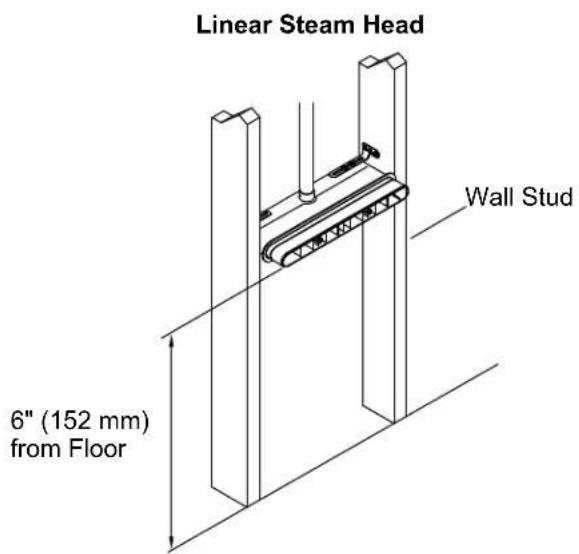
2. Determine the Location of the Steam Heads
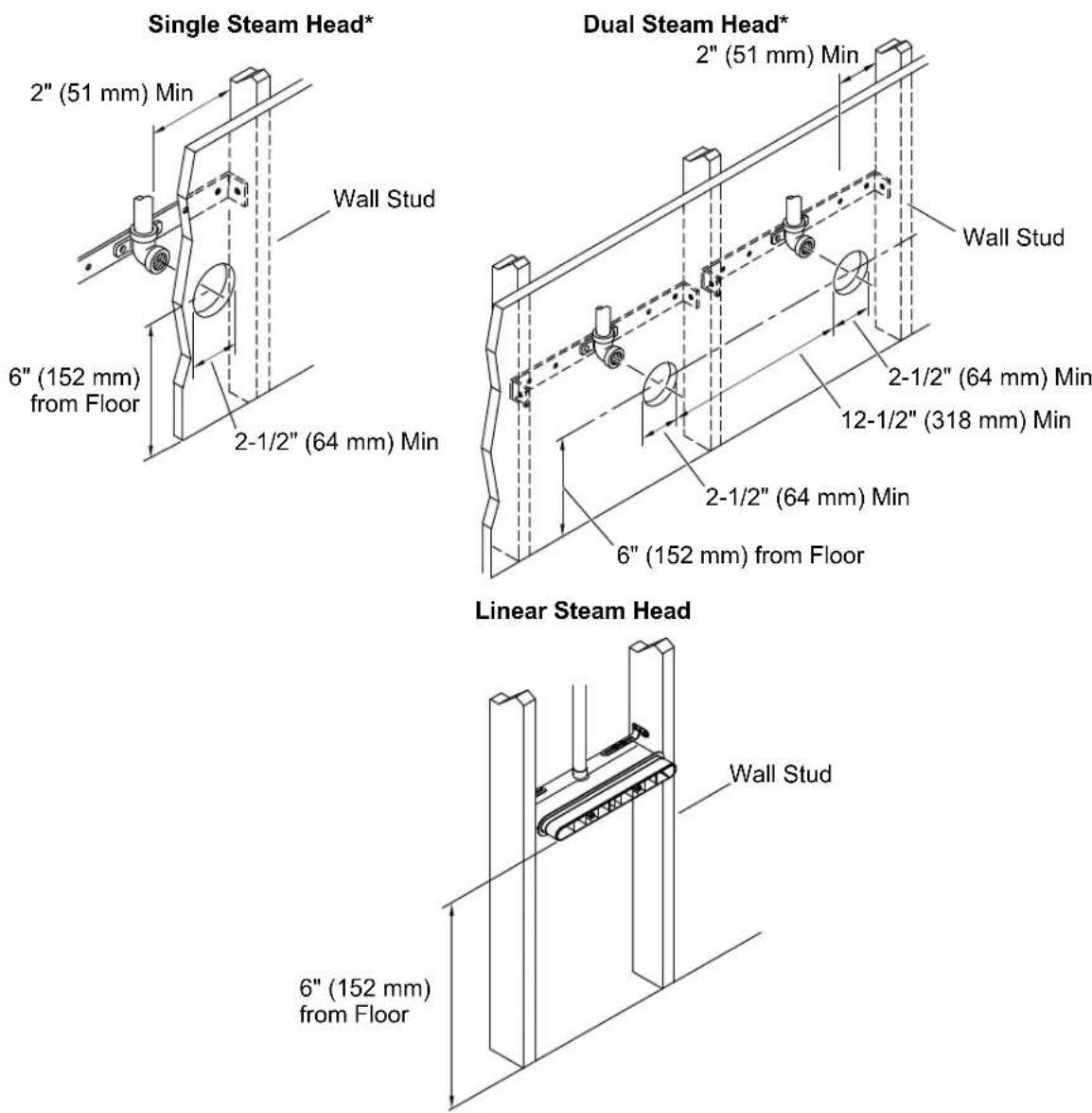
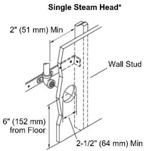
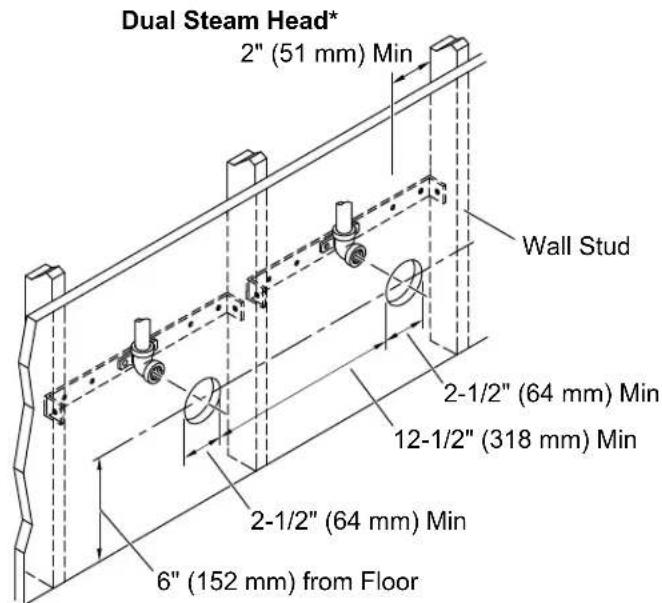
*Applies to square and round steam heads.

WARNING: Risk of personal injury. Do not install the steam control user interface outside the steam enclosure. The user interface must be installed within the enclosure to allow the sensors to regulate the temperature and control the flow of steam.

WARNING: Risk of scalding. Do not block the steam head or locate the steam head near a seat or bench, as the steam head is hot during operation and may scald the user.
IMPORTANT! Do not install the control directly above or in-line with the steam head.
NOTICE: When installing the control kit, allow room in the control cable for a drip loop. The drip loop will discourage moisture from following the control cable to the steam generator.
NOTE: All dimensions should be taken from the inside of the shower. Refer to the steam head and control Installation Instructions for more dimensional and installation information.
☐ Dual steam heads can be installed on opposite walls to improve steam distribution.
☐ Determine the steam head location. Locate the steam head(s) 6" (152 mm) above the shower floor. The steam head location should be within 25' (7.62 m) of the steam generator.
□ Determine the steam head location. Refer to the steam head Installation Instructions.
☐ For single steam head installations, determine the steam control user interface location on the wall opposite the steam head.
☐ For dual steam head installations, determine the steam control user interface location on a different wall than the steam heads. Locate the user interface as far from the steam heads as practical.
☐ Locate the steam control user interface 60" (1524 mm) above the floor of the shower.
☐ Verify that there is adequate clearance between the steam lines and any surrounding surfaces.
3. Install the Electrical Supply
| Model K-32324- | NA K-32325-NA | K-32326-NA K-32 | 327-NA K-32332- | NA K-32333-NA | ||
| Generator Size 5 | kW 7 kW 9 kW 1 | 1 kW 18 kW (Two | 9 | kW Steam Generators) | 22 kW (Two 11 kW Steam Generators) | |
| Required Electrical Service | ||||||
| Generator Dedicated Circuit #1 | 240 V, 40 A, 50/60 Hz | 240 V, 50 A, 50/60 Hz | 240 V, 60 A, 50/60 Hz | 240 V, 60 A, 50/60 Hz | 240 V, 60 A, 50/60 Hz | 240 V, 60 A, 50/60 Hz |
| Generator Dedicated Circuit #2 | n/a n/a n/a n/a 2 | 40 V, 60 A, | 50/60 Hz | 240 V, 60 A, 50/60 Hz | ||
| Product Electrical Rating | 240 V, 27 A, 60 Hz | 240 V, 36 A, 60 Hz | 240 V, 45 A, 60 Hz | 240 V, 46 A, 60 Hz | *240 V, 45 A, 60 Hz | *240 V, 46 A, 60 Hz |
*For dual installations only: Each steam generator requires a dedicated circuit rated at 240 V, 60 A, 60 Hz.

WARNING: Risk of electrocution. Disconnect all power before performing these installation steps.
NOTICE: Each steam generator requires a dedicated circuit. Dual steam generator installations require a second dedicated circuit.
□ Follow all local plumbing, building, and electrical codes. All electrical work should be done by a qualified electrician.
☐ In the chart above, find the electrical supply requirements for your steam generator.
□ Install the appropriate electrical supply (install 2 dedicated supplies for dual steam generator installations).
4. Install the Steam Generator

WARNING: Risk of property damage. There must be a minimum of 6" (152 mm) of air space surrounding the steam generator on at least three sides. This provides an area for the heat generated by the unit to dissipate.
IMPORTANT! Install the steam generator in a well ventilated and temperature-controlled location.
NOTICE: For optimum performance, install the steam generator as close as possible to the steam head. The steam generator must be installed within 25' (7.62 m) of the steam head.
☐ Install the desired drain pan at the steam generator location. Kohler Co. recommends using a KOHLER drain pan.
IMPORTANT! If a KOHLER drain pan is NOT being used, construct the support blocks using heat-resistant material.
□ Position the steam generator on the support blocks.
5. Install the Waterline and Steam Line
*Applies to square and round steam heads.

WARNING: Risk of personal injury or property damage. Do not plumb the pressure relief valve into the steam line. Plumbing the pressure relief valve into the steam line can create a hazard if the steam line is blocked or obstructed.

WARNING: Risk of scalding. Do not plumb a trapway, shut-off valve, or pressure relief valve into the steam line. Plumbing the pressure relief valve into the steam line can be hazardous if the steam outlet is capped.

WARNING: Risk of scalding. Do not connect the drain valve outlet to the steam line. Verify that there are no valleys or dips in the steam line.

WARNING: Risk of personal injury or property damage. Do not direct the pressure relief valve to the enclosure. In the event the pressure relief valve activates, the hot water may spray causing burns to the user and/or damage to the enclosure. Therefore, the pressure relief valve should be directed to an area where damage will not occur from contact with hot water and should conform to national and local plumbing codes.
Model Product Information
| Model K-32324- | NA K-32325-NA | K-32326-NA K-32 | 327-NA K-32332- | NA K-32333-NA | ||
| Weight 29 lb (13 | 2 kg) 29 lb (13.2 kg) | 29 lb (13.2 kg) | 29 lb (13.2 kg) 48 lb (21.8 kg) | 48 lb (21.8 kg) | ||
| Water Supply 1/2" copper line 1/2" | copper line 1/2" | copper line 1/2" | copper line 1/2" | copper line 1/2" | copper line 1/2" | copper line |
| Steam Line 1/2" | copper line 1/2" | copper line 1/2" | copper line 1/2" | copper line 1/2" | copper line 1/2" | copper line |
| Pressure Relief Valve(supplied) | 3/4 NPT female thread | 3/4 NPT female thread | 3/4 NPT female thread | 3/4 NPT female thread | 3/4 NPT female thread | 3/4 NPT female thread |
| Drain Line Valve | 3/8 NPT 3/8 NPT | 3/8 NPT 3/8 NPT | 3/8 NPT 3/8 NPT |
Install the Waterline to the Generator
IMPORTANT! The steam generator is compatible with installations that require a water-hammer arrestor or pressure-reducing valve to achieve optimal performance.
NOTE: For all NPT threaded connections, use pipe tape or pipe sealant. Do not overtighten the fittings.
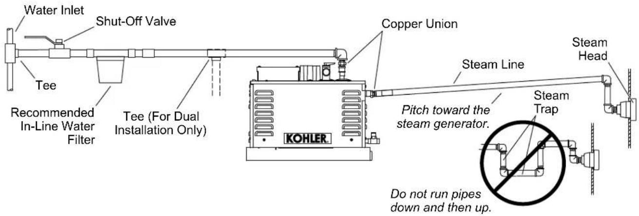
☐ Connect to an existing cold waterline, and run a 1/2" cold waterline to a shut-off valve before the in-line water filter.
☐ Before final connection to the steam generator, flush out the water supply line into a large pail. This removes any debris, silt, sand, or other material that may be in the line. Verify that the filter screen is in place in the water inlet tube.
☐ Install 1/2" copper tubing with a union fitting (supplied with the steam generator) located as close as possible to the steam generator.
□ Connect the water supply line to the steam generator.
☐ Turn ON the water supply, and fill the steam generator with water. Check for leaks.
☐ Check that the water drain valve on the generator is closed.
☐ If the water supply line is exposed to cold areas, insulate the piping to prevent freezing.
Install the Steam Line

WARNING: Risk of scalding. Do not block the steam head or locate the steam head near a seat or bench, as the steam head is hot during operation and may scald the user.
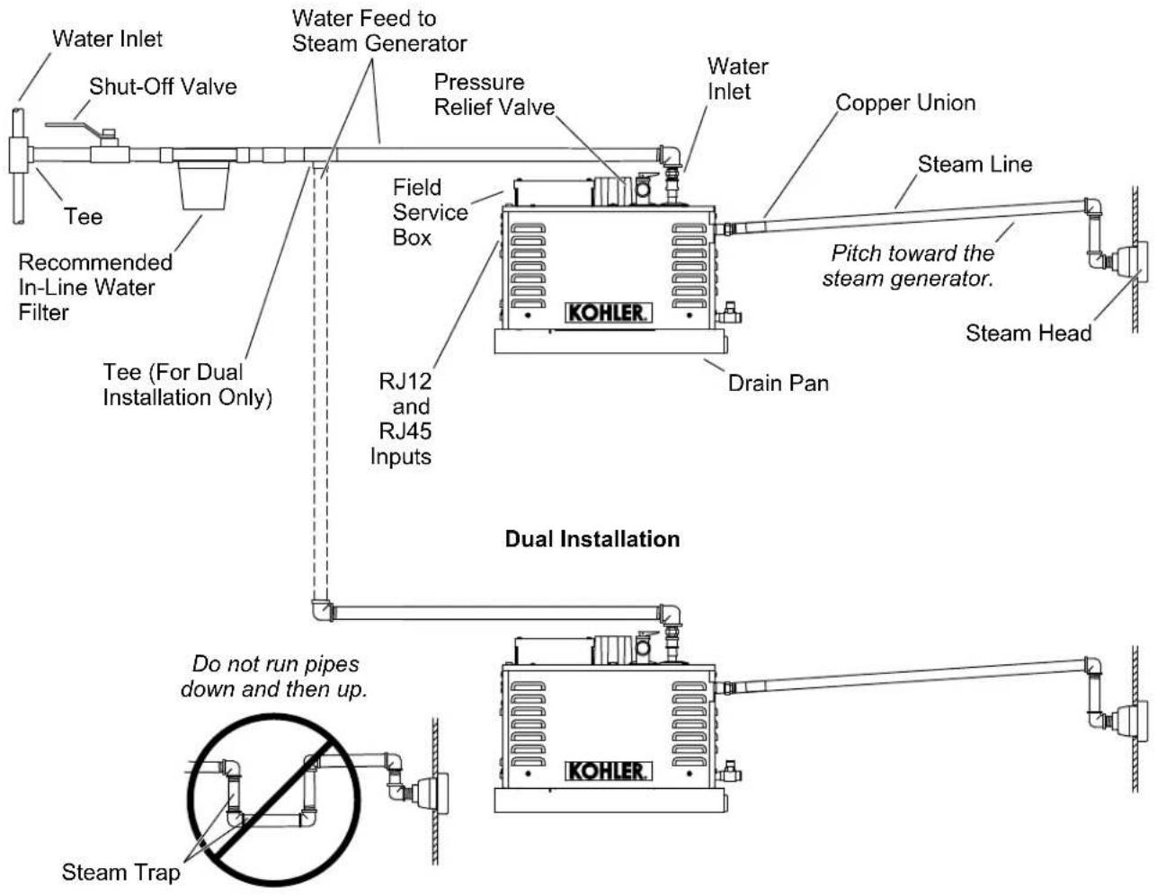
NOTICE: Do not install the slope of the steam line down, then up. If the slope of the steam line is down and then up, the steam will be trapped and block the flow of steam. Install the steam line at an incline to the steam head, at a pitch of 3/8" (10 mm) - 1/2" (13 mm) per 12" (305 mm) of pipe.
NOTICE: Provide clearance between the back wall and the elbow leading into the steam housing. The elbow must not contact any wall material.
NOTICE: Provide clearance between the steam line and surrounding surfaces.
NOTICE: Do not apply excessive heat to the generator connections when you solder connections. Do not apply flux or acids directly to the steam generator, as damage to the seals, plastic components, and trim finish may result. Do not apply petroleum-based lubricants to the steam generator components, as damage may result.
NOTE: Use thread sealant tape or pipe sealant for threaded connections. Do not overtighten the fittings.
NOTE: Use a 1/2" copper tube for the steam line.
NOTE: For optimum performance, use 45^ elbows in the steam line when possible. The use of 90^ elbows may result in an increase of condensation in the steam line.
NOTE: Always install a union fitting (supplied) as close as possible to the steam generator.
□ Add blocking behind the desired steam head location.
☐ Install and secure a 1/2 NPT elbow to the blocking directly behind the desired steam head location.
☐ Install a temporary 1/2" copper nipple that extends through the finished wall.
6. Connect the Electrical Supply
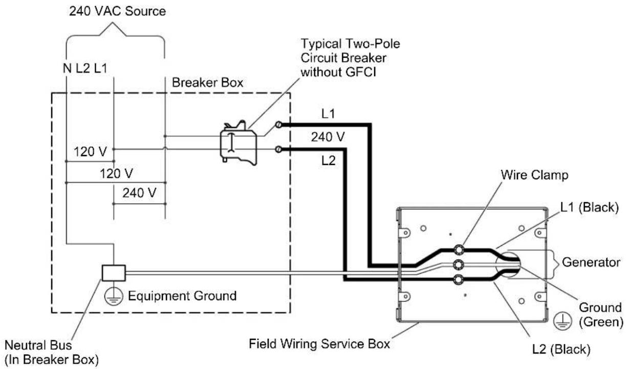

WARNING: Risk of electrocution. Disconnect all power before performing these installation steps.
IMPORTANT! DO NOT use wire nuts for electrical supply connections.
IMPORTANT! Verify that the water supply to the steam generator is turned ON before connecting the electrical supply.
NOTICE: All electrical work should be done by a qualified electrician.
NOTICE: All electrical wiring must be done in accordance with local codes.
NOTICE: Each steam generator requires a dedicated circuit. Dual steam generator installations require a second dedicated circuit.
NOTE: The wire clamps, field wiring, and circuit breaker are not provided.
☐ Turn OFF all electricity to the working area at the main circuit breaker panel.
☐ Connect a 240 VAC electrical line to the wires labeled "L1," "L2," and the green (ground) wire coming out of the field wiring service box with wire clamps (not provided).
□ Close the field service box.
□ Turn ON the main power.
☐ The digital display should read "Ld" or "Hd." If the digital display is not lit, consult the "Troubleshooting" section or contact the Customer Care Center.
7. Complete the Installation
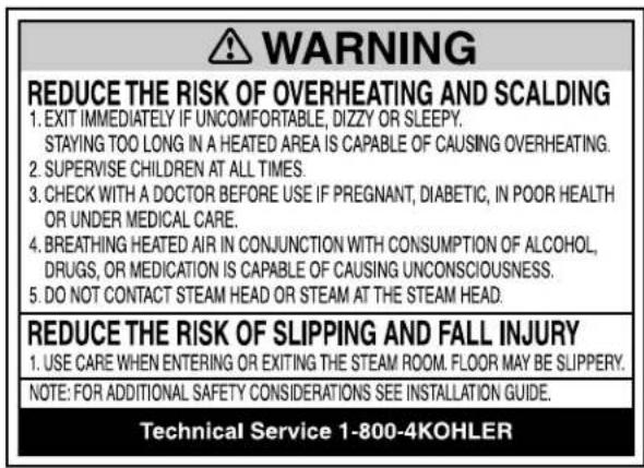
Warning Label
☐ Remove the adhesive backing from the warning label provided and apply the label to the wall of the shower or steam enclosure.
☐ Install the steam housing and steam head following the instructions packed with the steam head or steam control installation instructions.
☐ Remove the yellow tape from the control cable inputs.
☐ Install the steam control following the instructions packed with the steam control.
☐ To operate the steam control, follow the operating instructions provided with the steam control.
Fast Response Heater Enabled
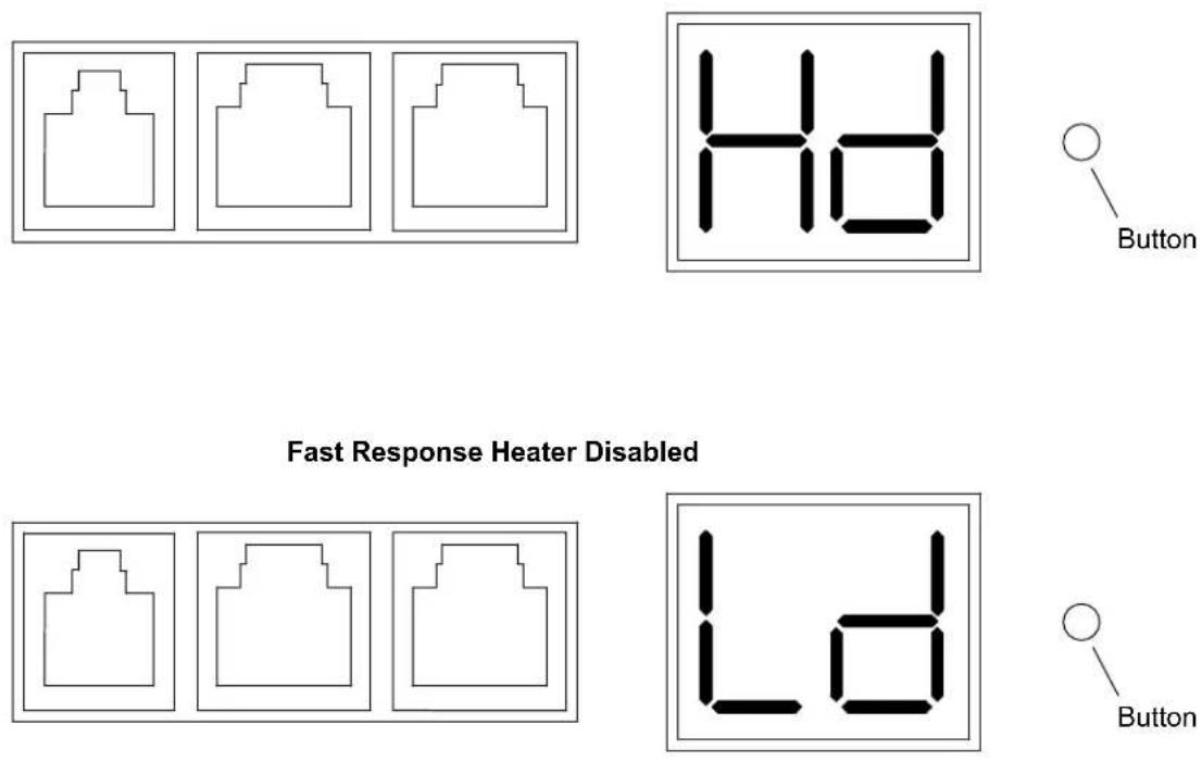
IMPORTANT! If this steam generator will be installed in a location that is 6000' (1829 m) above sea level, the fast response heater must be disabled.
☐ Press the button next to the digital display to enable or disable the fast response heater.

CAUTION: Risk of personal injury. Troubleshooting steps involving internal wiring or electrical connections should be performed by a qualified electrician.
NOTE: The troubleshooting steps below only apply to the steam generator itself. For issues involving the steam control, refer to the "Troubleshooting" section of the steam control instructions.
NOTE: For service parts information, visit your product page at kohler.com/serviceparts.
This troubleshooting guide is for general aid only. For service and installation issues and concerns, call 1-800-4KOHLER.
Error Codes
| Error Code Description | |
| 01 The water level is low, causing the temperature to rise. | |
| 02 The steam generator is below the expected temperature. | |
| 03 The steam generator is below the expected temperature. | |
| 04 The steam generator is above the expected temperature. | |
| 05 The steam generator is above the expected temperature. | |
| 08 Communication error. | |
| 10 Steam valve electrical failure. | |
| 20 Steam valve mechanical failure. See the "Error Code Troubleshooting" section below. | |
| 30 Power clean valve electrical failure. | |
| 40 Power clean valve mechanical failure. See the "Error Code Troubleshooting" section below. | |
| 50 Water level sensor failure. | |
| 60 Main heater relay failure. | |
| 70 Main heater failure. | |
| 80 Fast response heater failure. | |
| 90 The control panel button is stuck. | |
Error Code Troubleshooting
| Error Code Probable Cause Recommended Action | ||
| 20 | A. The shut-off valve is closedB. The drain valve is open.C. Steam valve mechanical failure. | A. Verify that the shut-off valve is open.B. Verify that the drain valve is closed.C. Contact the Customer Care Center. |
| 40 | A. The shut-off valve is closedB. The drain valve is open.C. Power clean valve mechanical failure. | A. Verify that the shut-off valve is open.B. Verify that the drain valve is closed.C. Contact the Customer Care Center. |
Installation Troubleshooting
| Symptoms Probable Causes Recommended Action | ||
| 1. The digital display is OFF and steam is not emitting from the steam head. | A. No electrical power at the steam generator.B. The circuit breaker is in the OFF position.C. The circuit breaker is not the correct size.D. The electrical connection in the steam generator field service box is loose. | A. Reset the electrical power at the circuit breaker. Have a qualified electrician verify that 240 V of power is present at the steam generator.B. Turn ON the electrical power at the circuit breaker.C. Verify that the circuit breaker is the correct size. Replace the circuit breaker if the size is incorrect.D. Turn OFF all electrical power to the steam generator. Have a qualified electrician open the steam generator field service box and check/repair the connections. |
| 2. The digital display is showing an error code and steam is not emitting from the steam head. Refer to the "Error Codes" section for a list of error codes. | A. The water is turned OFF.B. The inlet screen is clogged.C. There is excessive back pressure caused by piping that is too long or piping that contains too many 90° elbows.D. The steam control is not connected. | A. Turn ON the water supply.B. Remove and clean the inlet screens.C. Relocate the steam generator closer to the steam head or use 45° elbows.D. Check the wiring connections according to the team control installation instructions. If needed, use the provided troubleshooting kit to troubleshoot connection issues. |
| 3. Steam is emitting from the steam head, but the steam control is turned OFF. | A. Elevations greater than 6000' (1829 m) above sea level may cause water to boil at lower temperatures. | A. Disable the fast response heater. Refer to the "Enabling/Disabling the Fast Response Heater" section. |
This device complies with Part 15 of the FCC Rules. Operation is subject to the following two conditions: (1) this device may not cause harmful interference, and (2) this device must accept any interference received, including interference that may cause undesired operation.
Changes or modifications not expressly approved by the party responsible for compliance could void the user's authority to operate the equipment.
This equipment has been tested and found to comply with the limits for a Class B digital device, pursuant to Part 15 of the FCC Rules. These limits are designed to provide reasonable protection against harmful interference in a residential installation. This equipment generates, uses, and can radiate radio frequency energy and, if not installed and used in accordance with the instructions, may cause harmful interference to radio communications. However, there is no guarantee that interference will not occur in a particular installation. If this equipment does cause harmful interference to radio or television reception, which can be determined by turning the equipment off and on, the user is encouraged to try to correct the interference by one of the following measures:
- Reorient or relocate the receiving antenna.
- Increase the separation between the equipment and receiver.
- Connect the equipment into an outlet on a circuit different from that to which the receiver is connected.
- Consult the dealer or an experienced radio/TV technician for help.
This Class B digital apparatus complies with Canadian ICES-003.
natural_image
Collection of various industrial tools and components, including eyeglasses, wrenches, pliers, and spools (no text or labels visible)NOTE: FOR ADDITIONAL SAFETY CONSIDERATIONS SEE INSTALLATION GUIDE.
Technical Service 1-800-4KOHLER
natural_image
Three identical abstract geometric shapes outlined in black outlines within rectangular frames (no text or symbols)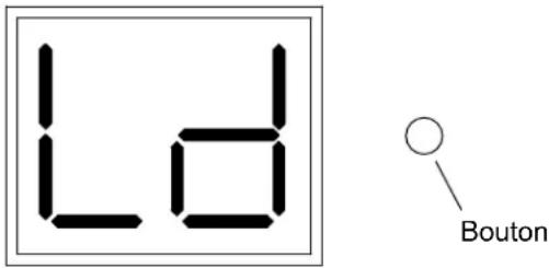
natural_image
Collection of various industrial tools and components, including glasses, screwdriver, wrench, pliers, and motor (no text or labels visible)Corona perforadora de 1-1/4 pulg y 2-1/2 pulg Soplete de propano Cortatubos Soldadura