Atmo K-34455 - Fan KOHLER - Free user manual and instructions
Find the device manual for free Atmo K-34455 KOHLER in PDF.

| Product Type | Bathroom Fan with LED Lighting Option |
| Brand | Kohler |
| Model | Atmo K-34455 |
| Power Supply | 120 V ~ 60 Hz |
| Recommended Duct | 6 in (152 mm) Rigid Metal |
| Estimated Airflow | 80 CFM (typical value) |
| Estimated Sound Level | 1.5 sones (typical value) |
| Estimated Dimensions (Housing) | 11 x 11 x 7 in (28 x 28 x 18 cm) |
| Estimated Weight | 2.3 kg (5 lb) |
| Housing Material | Painted Steel |
| Main Functions | Ventilation, integrated LED lighting (depending on model) |
| Speed Switch | 3 adjustable speeds |
| Required Protection | GFCI circuit breaker (ground fault) |
| Warranty | Limited 3-year warranty |
| Replacement Parts | Available at kohler.com/serviceparts |
| Maintenance and Cleaning | Regularly clean the fan and ducts |
| Energy Standards | ENERGY STAR certified |
| Safety | Disconnect power before servicing |
| Installation | Ceiling mounted, exhaust to outside |
| Usage | General ventilation only |
Frequently Asked Questions - Atmo K-34455 KOHLER
User questions about Atmo K-34455 KOHLER
0 question about this device. Answer the ones you know or ask your own.
Ask a new question about this device
Download the instructions for your Fan in PDF format for free! Find your manual Atmo K-34455 - KOHLER and take your electronic device back in hand. On this page are published all the documents necessary for the use of your device. Atmo K-34455 by KOHLER.
USER MANUAL Atmo K-34455 KOHLER
Installation Instructions
Bathroom Ceiling Fan
Record your model number:
Need help? Contact our Customer Care Center.
• USA/Canada: 1-800-4KOHLER (1-800-456-4537) Mexico: 001-800-456-4537
• Service parts: kohler.com/serviceparts
• Care and cleaning: kohler.com/clean
• Patents: kohlercompany.com/patents
Warranty
This product is covered under the KOHLER® Bath Fan Three-Year Limited Warranty, found at kohler.com/warranty. For a hardcopy of warranty terms, contact the Customer Care Center.
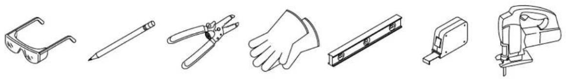
Tools and Materials
natural_image
Illustration of various household electronics including glasses, pencils, hand tools, and a mechanical device (no text or symbols)Plus:
- Duct Clamps
- 2x6 Support Block
READ AND FOLLOW ALL INSTRUCTIONS

WARNING: When using electrical products, basic precautions should always be followed, including the following:

DANGER: Risk of electric shock. Disconnect the electricity to the working area at the main breaker panel before performing installation steps for hardwiring.

WARNING: Risk of electric shock. Disconnect the power before servicing.

WARNING: Risk of injury or property damage. To reduce the risk of fire or electric shock, do not use this fan with any solid-state speed control device.

CAUTION: Risk of personal injury. For general ventilating use only. Do not use to exhaust hazardous or explosive materials and vapors.
IMPORTANT! The R value of the ceiling thermal insulation used must not exceed R60.

WARNING: To reduce the risk of fire, electric shock, or injury to persons, observe the following:
Use this unit only in the manner intended by the manufacturer. If you have questions, contact the manufacturer.
Before servicing or cleaning unit, switch power off at service panel and lock the service disconnecting means to prevent power from being switched on accidentally. When the service disconnecting means cannot be locked, securely fasten a prominent warning device, such as a tag, to service the panel.
Installation work and electrical wiring must be done by qualified person(s) in accordance with all applicable codes and standards, including fire-rated construction.
Sufficient air is needed for proper combustion and exhausting of gases through the flue (chimney) of fuel burning equipment to prevent back drafting. Follow the heating equipment manufacturer's guideline and safety standards such as those published by the National Fire Protection Association (NFPA), and the American Society for Heating, Refrigeration and Air Conditioning Engineers (ASHRAE), and the local code authorities.
When cutting or drilling into a wall or ceiling, do not damage the electrical wiring and other hidden utilities.
Ducted fans must always be vented to the outdoors.
If this unit is to be installed over a bath or shower, the unit must be marked as appropriate for the application and be connected to a GFCI (Ground Fault Circuit Interrupter) – protected branch circuit.
Follow all local plumbing, building, and electrical codes.
SAVE THESE INSTRUCTIONS

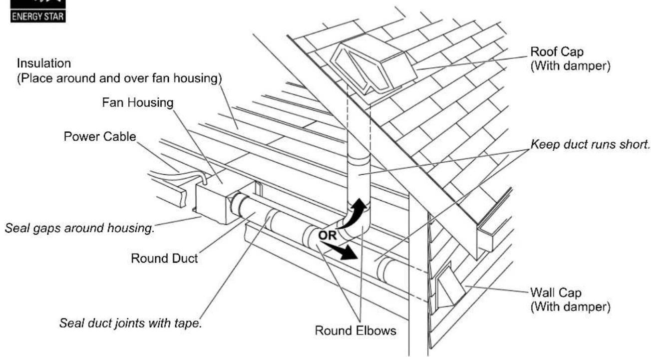
The ducting has a strong effect on the air flow, noise, and energy use of the fan. Use the shortest, straightest duct routing possible for best performance, and avoid installing the fan with smaller ducts than recommended. Insulation around the ducts can reduce energy loss and inhibit mold growth. Fans installed with existing ducts may not achieve their rated air flow.
6" (152 mm) round rigid metal duct is recommended for best performance.
Verify that the duct joints and exterior penetrations are sealed with caulk or other similar material to create an air-tight path, minimize building heat loss/gain, and to reduce the potential for condensation.
Place or wrap insulation around the duct and/or fan to minimize possible condensation buildup within the duct, as well as minimize building heat loss/gain.
1. Prepare the Site
IMPORTANT! One side of the hole must align with a joist.
NOTE: It is recommended that an additional 2x6 vertical support block is constructed on the side of the hole opposite the joist. Use the provided support block if an additional 2x6 vertical support cannot be constructed.
□ Remove the old fan if installing in an existing fan location.
☐ Patch or enlarge the ceiling hole using the provided template taking care to align one edge of the hole with a joist.
☐ Install a 2x6 vertical support block on the edge of the hole opposite the joist. If this is not possible, install the provided support block using the following steps.
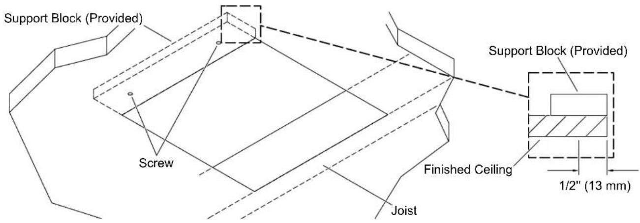
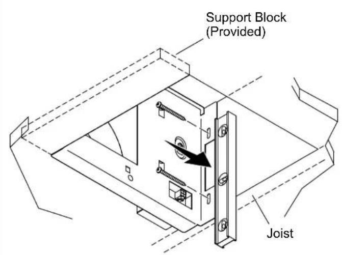
Support Block Installation
NOTE: The screws used to attach the support block to the finished ceiling must be located 1/2" (13 mm) or closer to the edge of the hole to allow the fan box flange to cover the screws.
□ Align the support block with the edge of the ceiling hole inside the finished ceiling.
☐ Secure the provided support block behind the ceiling drywall using screws (not provided).
2. Install the Duct Connector
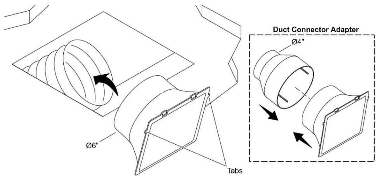
NOTE: If the duct is 4", use the duct connector adapter.
☐ Secure the duct connector to the duct using a duct clamp.
□ Verify that the duct connector is positioned at the edge of the hole with the tabs at the top.
3. Connect the Wires
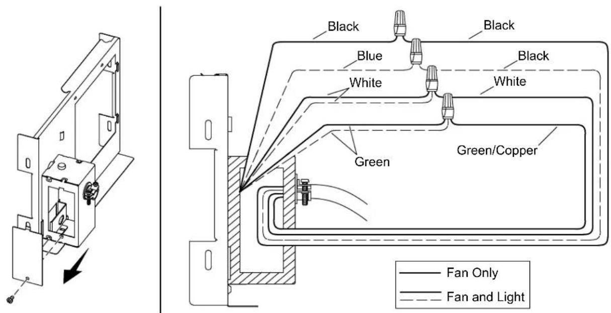
□ Remove the side panel on the junction box.
□ Carefully run the ceiling wires through the hole in the back of the junction box.
☐ Pull the junction panel wires and the ceiling wires through the side opening on the junction box to connect.
Fan Only
☐ Attach the ground wire (usually bare copper or green) from the junction box to the ground wire (green) from the junction panel.
☐ Attach the neutral wire (usually white) from the junction box to the neutral wire (white) from the junction panel.
☐ Attach the hot wire (usually black) from the junction box to the fan wire (black) from the junction panel.
Fan and Light
NOTE: Attach the lighting wire and the fan wire to separate hot wires to operate the light and fan from separate switches (shown). Attach the lighting wire and the fan wire to the same hot wire to operate the light and the fan from the same switch.
☐ Attach the ground wire (usually bare copper or green) from the junction box to both ground wires (green) from the junction panel.
☐ Attach the neutral wire (usually white) from the junction box to both neutral wires (white) from the junction panel.
□ Attach the hot wire (usually black) from the junction box to the fan wire (black) from the junction panel.
□ Attach the hot wire (usually black) from the junction box to the lighting wire (blue) from the junction panel.
All Models
☐ Secure the wires together with the provided wire nuts.
□ Wrap the wire nuts with electrical tape.
□ Verify that all plastic wire nuts are securely fastened and strands of bare wire are not exposed.
☐ Tuck all connected wires into the junction box and secure the junction box panel back onto the side of the junction box.
4. Install the Junction Panel
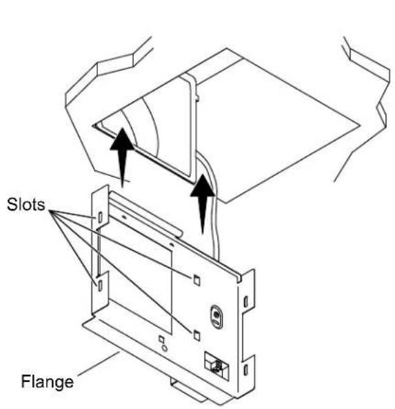
☐ Slide the junction panel into the ceiling. Verify that the slots on the junction panel slide over the edges of the duct connector.
☐ Verify that the flange on the junction panel stays below the finished ceiling when installed.
□ Verify that the junction panel is level.
☐ Secure the junction panel to the joist using the provided screws.
☐ If a 2x6 vertical support block was used, secure the other side of the junction panel to the support block with two more provided screws. If the provided support block was used, the other side of the junction panel does not have to be secured.
5. Install the Fan Box
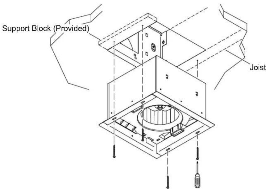

CAUTION: Risk of personal injury. Fan box edges are sharp. Use proper protective equipment when handling the fan box.
☐ Verify that the exhaust hole in the fan box aligns with the square hole in the junction panel.
☐ Slide the fan box into the ceiling.
☐ Secure the fan box to the joist and the 2x6 support block or the provided support block using the provided screws.
6. Connect the Fan Wires
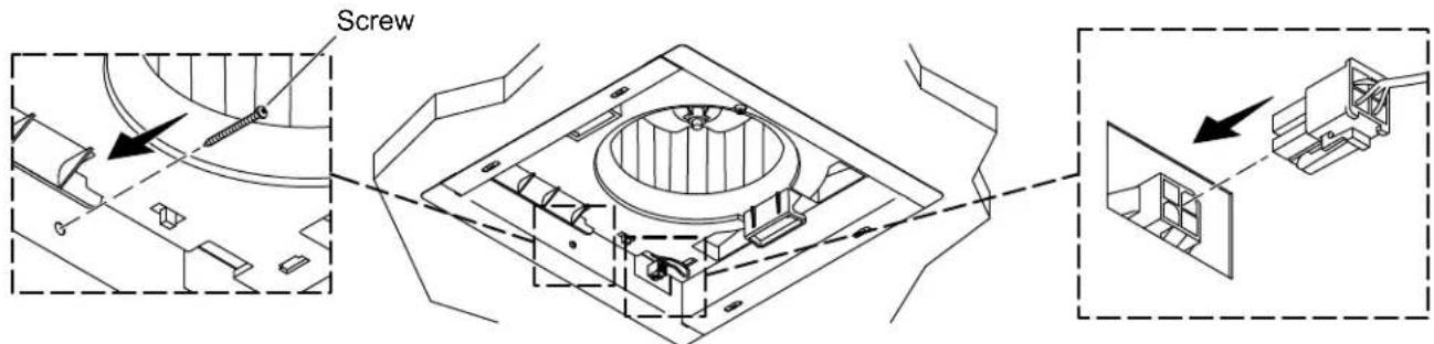
☐ Secure the fan box to the junction panel with the provided screw.
□ Connect the quick-connect wire from the fan box to the connection point on the junction panel.
7. Install the Cover
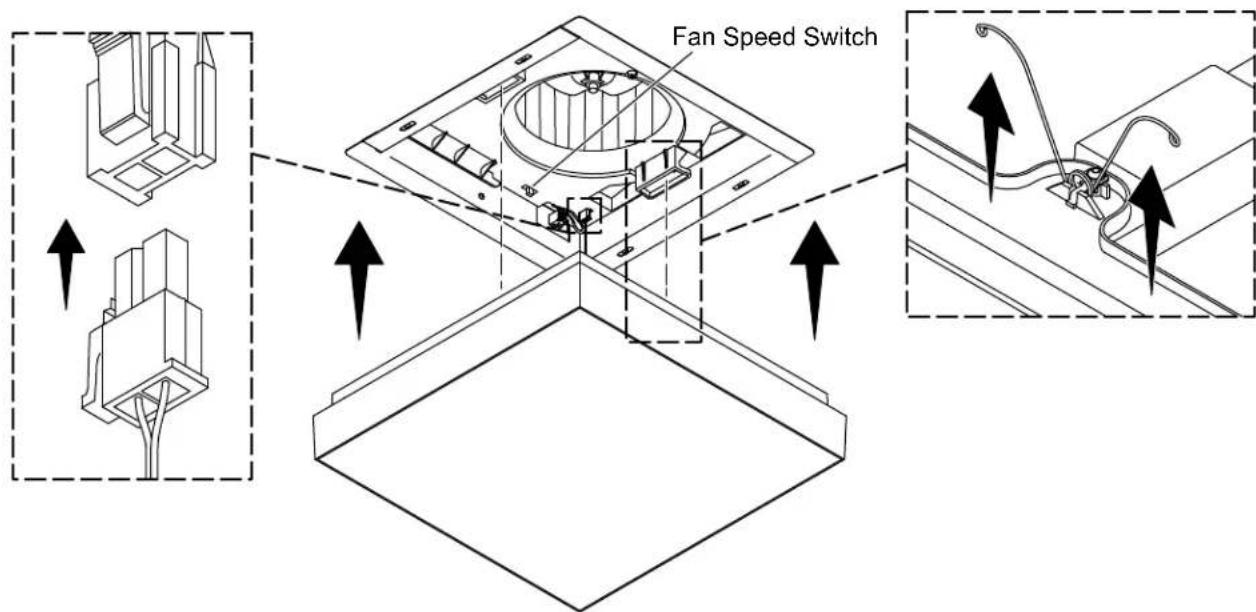
☐ Lighted Models Only: Connect the quick connect wire from the cover to the connection point in the fan box.
□ Move the Fan Speed Switch to the desired fan speed.
□ Compress the tension springs on the cover and insert the springs into the slots in the fan box.
☐ Push the cover up until the cover is flush with the ceiling.
This troubleshooting guide is for general aid only. For warranty service, contact your dealer or wholesale distributor, or contact the Customer Care Center using the information located in the front of this manual.
| Symptoms Probable Cause | Recommended Action | |
| 1. The blower is not working. | A. No power to the fan.B. The motor is damaged. | A. Check the circuit breaker. Check wire connections in fan junction box.B. Replace the fan box. |
| 2. The blower noise level increased. | A. Loose blower nut.B. Build up of dust particles.C. Blocked vent. | A. Tighten the nut with a wrench.B. Clean the blower to remove dust.C. Clean the vent to remove blockage. |
| 3. Lighted Models: Light is not working. | A. No power to the fan.B. The wire from the light cover is not connected.C. The LED board is damaged.D. Power supply failure. | A. Check the circuit breaker. Check the wire connections in the fan junction box.B. Lower the light cover and connect the wire to the fan box.C. Replace the light cover.D. Replace the light cover. |
| 4. Lighted Models: Light flickering while dimming. | A. The dimmer switch is not working or the dimmer is not LED compliant. | A. Replace the dimmer with a recommended TRIAC dimmer for LEDs. |
natural_image
Line drawings of various household electronics including glasses, pencil, scissors, hand, ruler, and switch (no text or symbols)Plus :
- Brides de collier
- Bloc de support 2x6
LIRE ET SUIVRE TOUTES LES INSTRUCTIONS